maharashtra state board of technical education...
TRANSCRIPT
MAHARASHTRA STATE BOARD OF TECHNICAL EDUCATION (Autonomous)
(ISO/IEC - 27001 - 2005 Certified)
SUMMER – 2016 EXAMINATION Subject Code : 17302 Model Answer
----------------------------------------------------------------------------------------------------------------------------- --------------------- Important Instructions to examiners: 1) The answers should be examined by key words and not as word-to-word as given in the model answer scheme. 2) The model answer and the answer written by candidate may vary but the examiner may try to assess the understanding level of the candidate. 3) The language errors such as grammatical, spelling errors should not be given more Importance (Not applicable for subject English and Communication Skills. 4) While assessing figures, examiner may give credit for principal components indicated in the figure. The figures drawn by candidate and model answer may vary. The examiner may give credit for any equivalent figure drawn. 5) Credits may be given step wise for numerical problems. In some cases, the assumed constant values may vary and there may be some difference in the candidate’s answers and model answer. 6) In case of some questions credit may be given by judgement on part of examiner of relevant answer based on candidate’s understanding. 7) For programming language papers, credit may be given to any other program based on equivalent concept.
Question1. A) Attempt any Six (12)
a) A rectifier is an electronic circuit that converts alternating current (AC), which
periodically reverses direction, to direct current (DC), which flows in only one direction.
(1 Mark)
Types of rectifier:
Half wave rectifier
Full wave rectifier : Center tapped & Bridge rectifier
(1 Mark)
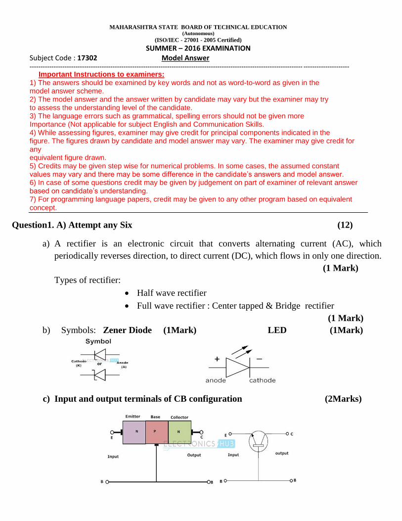
b) Symbols: Zener Diode (1Mark) LED (1Mark)
c) Input and output terminals of CB configuration (2Marks)

MAHARASHTRA STATE BOARD OF TECHNICAL EDUCATION (Autonomous)
(ISO/IEC - 27001 - 2005 Certified)
SUMMER – 2016 EXAMINATION Subject Code : 17302 Model Answer
----------------------------------------------------------------------------------------------------------------------------- ---------------------
d) Pin diagram of IC 555 :
Pin diagram – 1 Mark Label – 1 Mark
e) Logical symbol: 2:1 Multiplexer (1 Mark) Truth table (1 Mark)
f) Types of real time mechatronics system:
i. Hard real time system: System must react to the input within specific amount of
time(deadline) (1 Mark)
ii. Soft real time system: This system try to meet deadline, but it fails does not
cause any major damage. (1 Mark)
Any other relevant Mechatronics systems may also considered.

MAHARASHTRA STATE BOARD OF TECHNICAL EDUCATION (Autonomous)
(ISO/IEC - 27001 - 2005 Certified)
SUMMER – 2016 EXAMINATION Subject Code : 17302 Model Answer
----------------------------------------------------------------------------------------------------------------------------- ---------------------
g) V-I Characteristics of P-N junction diode: (2 Marks)
h) Types of Bijunction transistor:
PNP transistor and NPN transistor (1 Mark)
Symbols with labels (1/2mark for each symbol = 1 Mark)
B) Attempt any TWO : (8 Marks)
i) Filter: A circuit which converts the pulsating DC into pure DC is called as filter. As
the name specifies it removes the ripples in the rectifier output and provides a pure DC at the output. The electronic reactive elements like capacitor and inductors are used in filter circuit to perform this operation. (1 Mark)
List types of Filter:
Choke input (Inductor) filter, Capacitor , LC filter and Pi (π) filter (1 Mark)

MAHARASHTRA STATE BOARD OF TECHNICAL EDUCATION (Autonomous)
(ISO/IEC - 27001 - 2005 Certified)
SUMMER – 2016 EXAMINATION Subject Code : 17302 Model Answer
----------------------------------------------------------------------------------------------------------------------------- ---------------------
Any one circuit of the followings: (2 Marks)
Choke input (Inductor) Filter
LC Filter Pi filter
ii) Non-inverting op-amp circuit: (2 Marks)
Given: Rf =15 kΩ, Ri = 5kΩ
Gain is the ratio of output voltage to the input voltage and is denoted by AV.
For Non-inverting op-amp, gain is expressed by : AV = 1+Rf/Ri
Therefore; Av = 1+ 15kΩ/5kΩ = 1+3 = 4
Av = 4 (2Marks)

MAHARASHTRA STATE BOARD OF TECHNICAL EDUCATION (Autonomous)
(ISO/IEC - 27001 - 2005 Certified)
SUMMER – 2016 EXAMINATION Subject Code : 17302 Model Answer
----------------------------------------------------------------------------------------------------------------------------- ---------------------
iii) PLC : Programmable Logic Controller (PLC) or programmable
controller is a digital computer used for automation of typically industrial
electromechanical processes, such as control of machinery on factory assembly
lines, amusement rides, or light fixtures. PLCs are used in many machines, in
many industries. Or (2Marks)
“A digitally operated electronic system, designed for use in an industrial environment,
which uses a programmable memory for the internal storage of user-oriented instructions
for implementing specific functions such as logic sequencing, timing counting and
arithmetic to control through digital or analog inputs and outputs, various types of
machines or processes.”
(Any other appropriate definition may also be considered.)
Architecture: (2Marks)
OR
MAHARASHTRA STATE BOARD OF TECHNICAL EDUCATION (Autonomous)
(ISO/IEC - 27001 - 2005 Certified)
SUMMER – 2016 EXAMINATION Subject Code : 17302 Model Answer
----------------------------------------------------------------------------------------------------------------------------- ---------------------
Question 2: Attempt any four
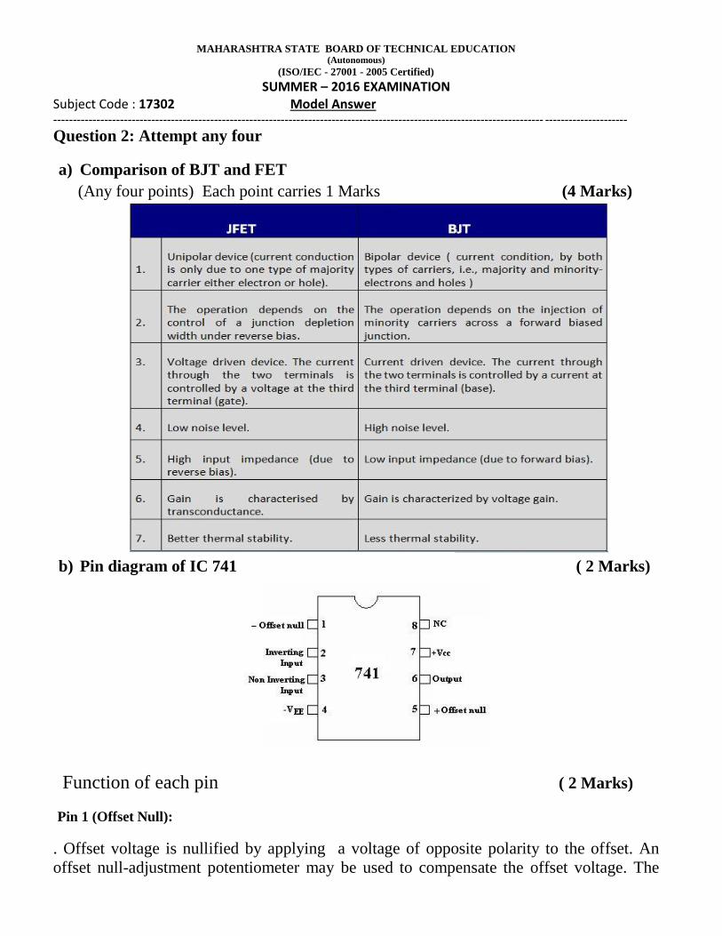
a) Comparison of BJT and FET
(Any four points) Each point carries 1 Marks (4 Marks)
b) Pin diagram of IC 741 ( 2 Marks)
Function of each pin ( 2 Marks)
Pin 1 (Offset Null):
. Offset voltage is nullified by applying a voltage of opposite polarity to the offset. An
offset null-adjustment potentiometer may be used to compensate the offset voltage. The
MAHARASHTRA STATE BOARD OF TECHNICAL EDUCATION (Autonomous)
(ISO/IEC - 27001 - 2005 Certified)
SUMMER – 2016 EXAMINATION Subject Code : 17302 Model Answer
----------------------------------------------------------------------------------------------------------------------------- ---------------------
null-offset potentiometer also compensates the irregularities in operational amplifier
manufacturing process which may cause an offset. Consequently, the null potentiometer is
recommended.
Pin 2 : (Inverting Input)
All input signals at this pin gets inverted at output pin 6. When input signal is applied to
this pin the output voltage is out of phase with input. Negative sign (-) represents the
Inverting input terminal.
Pin 3 : (Non-Inverting Input):
All input signals at this pin will be processed normally without inversion. The rest is the
same as pin 2. When input signal is applied to this pin the output voltage is in phase with
input.
Pin 4: (-VEE):
This pin is also referred as -Vss) which is negative supply voltage terminal. Supply-
voltage operating range for the 741 is -4.5 volts (minimum) to -18 volts (max), and it is
specified for operation between -5 and -15 Vdc. The device will operate essentially the
same over this range of voltages without change in timing period. Sensitivity of time
interval to supply voltage change is low, typically 0.1% per volt. (Note: Do not confuse the
-V with ground).
Pin 5 (Offset Null):
Connecting 10KΩ potentiometer between pin 1 & 5 makes offset voltage zero.
Pin 6: (Output)
Output signal´s polarity will be the opposite of the input´s when this signal is applied to the
op-amp´s inverting input. The output of op-amp is derived at this terminal with respect to
ground.
Pin 7 :(+VCC): This pin is the positive supply voltage terminal of the 741 Op-Amp IC. Supply-voltage
operating range for the 741 is +4.5 volts (minimum) to +18 volts (maximum), and it is
specified for operation between +5 and +15 Vdc. The device will operate essentially the
same over this range of voltages without change in timing period. Actually, the most
significant operational difference is the output drive capability, which increases for both
current and voltage range as the supply voltage is increased. Sensitivity of time interval to
supply voltage change is low, typically 0.1% per volt.

MAHARASHTRA STATE BOARD OF TECHNICAL EDUCATION (Autonomous)
(ISO/IEC - 27001 - 2005 Certified)
SUMMER – 2016 EXAMINATION Subject Code : 17302 Model Answer
----------------------------------------------------------------------------------------------------------------------------- ---------------------
Pin 8 :(NC) Not Connected.
NC means Not Connected´. There is no other explanation. There is nothing connected to
this pin, it is provided to make the IC as standard 8-pin package.
c) Thermal runway: (2 Marks)
Destruction of transistor due to excessive temperature is thermal runaway
The self-destruction of a transistor is known as thermal runway. It is the cyclic
process, which destroys the transistor.
The rise in collector-base junction takes place due to two reason:
Due to increase in the ambient temperature and due to internal Heating
An increase in collector current increases the power dissipated in the collector-base
junction of the transistor. This will increase the temperature of C-B junction. As the
transistor has a negative temperature coefficient of resistivity, increased junction
temperature reduces the resistance. The reduced resistance will increase the collector
current further. This becomes cumulative process which will finally damage the transistor
due to excessive internal heating. This process is known as “Thermal Runaway”.
Use of heat sink: (2 Marks)
A heat-sink is designed to remove heat from a transistor and dissipate it into the
surrounding air as efficiently as possible. Heat-sinks have many different forms, such as
finned aluminium or copper sheets or blocks, often painted or anodised matt black to help
dissipate heat more quickly. Good physical contact between the transistor and heat-sink is
essential, and a heat transmitting grease (heat-sink compound) is smeared on the contact
area before clamping the transistor to the heat-sink.
Where it is necessary to maintain electrical insulation between transistor and heat-sink a
mica layer is used between the heat-sink and transistor. Mica has excellent insulation and
very good heat conducting properties.
d) Oscillator: (1 Marks)
Oscillator is ac signal generator which is used in laboratories. It generates
alternating voltage of desired shape at desired frequency. The output voltage and frequency
of an oscillator can be variable. OR A circuit which generates oscillations (waveforms of desired frequency) at output or
generates output without any input is known as oscillator.

MAHARASHTRA STATE BOARD OF TECHNICAL EDUCATION (Autonomous)
(ISO/IEC - 27001 - 2005 Certified)
SUMMER – 2016 EXAMINATION Subject Code : 17302 Model Answer
----------------------------------------------------------------------------------------------------------------------------- ---------------------
The oscillator operates on dc supply and produces alternating output voltage
without any alternating input voltage.
Barkhausen criteria for oscillation: (2 Marks)
An amplifier will work as an oscillator when it satisfies a set of conditions called
‘Barkhausen Criteria”
Barkhausen criteria states that:
An oscillator will operate at that frequency for which the total phase shift
introduced, as the signal proceeds from the input terminals, through the amplifier
and feedback network and back again to the input is precisely 0 degree or 360
degree.
At the oscillator frequency, the magnitude of the product of open loop gain of
amplifier (A) and the feedback factor (β) is equal to or greater than unity
Aβ ≥ 1
List types of oscillator: (1 Marks)
On the basis of components used in the feedback network the oscillators are
classified into following categories:
1. RC oscillators
i)Phase shift oscillator ii) Wien bridge oscillator

MAHARASHTRA STATE BOARD OF TECHNICAL EDUCATION (Autonomous)
(ISO/IEC - 27001 - 2005 Certified)
SUMMER – 2016 EXAMINATION Subject Code : 17302 Model Answer
----------------------------------------------------------------------------------------------------------------------------- ---------------------
2. LC oscillators
i) Hartley oscillator ii) Colpitt’s oscillator iii) Clapp oscillator
3. Crystal oscillator
e) Differentiator circuit: (3 Marks)
(1 Mark) f) Symbols:
AND Gate
(1+1 Mark)

MAHARASHTRA STATE BOARD OF TECHNICAL EDUCATION (Autonomous)
(ISO/IEC - 27001 - 2005 Certified)
SUMMER – 2016 EXAMINATION Subject Code : 17302 Model Answer
----------------------------------------------------------------------------------------------------------------------------- ---------------------
NAND Gate
(1+1 Mark) Question 3: Attempt any four: (16 Marks)
(a) Instrumentation Amplifier ( 3 Marks)
(Component Values are optional)
Voltage Equation ( 1 Mark)
Vo = Av(V2-V1)
OR
Voltage equation (1 Mark)
Vo = Av(Va-Vb)
A B Y
0 0 1
0 1 1
1 0 1
1 1 0
A
B Y

MAHARASHTRA STATE BOARD OF TECHNICAL EDUCATION (Autonomous)
(ISO/IEC - 27001 - 2005 Certified)
SUMMER – 2016 EXAMINATION Subject Code : 17302 Model Answer
----------------------------------------------------------------------------------------------------------------------------- ---------------------
b)Comparison of Microprocessor and Microcontroller (4 Marks) Any four appropriate points (1 Mark for each appropriate point)
Any other appropriate point may also be considered.
c) Two stage RC coupled amplifier circuit: (3 Marks)
Frequency Response: (1 Mark)
MAHARASHTRA STATE BOARD OF TECHNICAL EDUCATION (Autonomous)
(ISO/IEC - 27001 - 2005 Certified)
SUMMER – 2016 EXAMINATION Subject Code : 17302 Model Answer
----------------------------------------------------------------------------------------------------------------------------- ---------------------
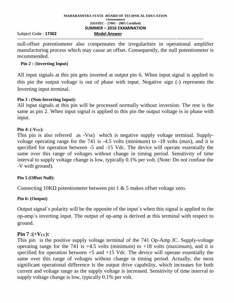
d) Full Wave Bridge rectifier circuit and waveforms: (3+1 Mark)
e) Mechatronics: (2 Marks)
Mechatronics is a synergistic combination of precision engineering, electronic control
and mechanic systems. It is the science, that exists at the interface among the other five
disciplines:
mechanics
electronics
informatics
automation
robotics
Applications of Mechatronics: (2 Marks)
Any four (Half mark each relevant application)
Artificial Intelligence and Expert Systems
Medical Imaging
Robotic applications
Military applications
Control applications
Automotive systems
Satellite system
(Any other appropriate application may also be considered.)
f) Block diagram of ADC (2 Marks)

MAHARASHTRA STATE BOARD OF TECHNICAL EDUCATION (Autonomous)
(ISO/IEC - 27001 - 2005 Certified)
SUMMER – 2016 EXAMINATION Subject Code : 17302 Model Answer
----------------------------------------------------------------------------------------------------------------------------- ---------------------
Function : (2 Marks)
A sample and hold circuit to acquire the input voltage (Vin).
An analog voltage comparator that compares Vin to the output of the internal
DAC and outputs the result of the comparison to the successive approximation
register (SAR).
A successive approximation register subcircuit designed to supply an
approximate digital code of Vin to the internal DAC.
An internal reference DAC that, for comparison with VREF, supplies the
comparator with an analog voltage equal to the digital code output of the SARin
Question 4: Attempt any four: (16 Marks)
a) Block diagram of CNC (2 Marks)

MAHARASHTRA STATE BOARD OF TECHNICAL EDUCATION (Autonomous)
(ISO/IEC - 27001 - 2005 Certified)
SUMMER – 2016 EXAMINATION Subject Code : 17302 Model Answer
----------------------------------------------------------------------------------------------------------------------------- ---------------------
Functions : (2 Marks)
Minicomputer with associated software performs the machine control unit (MCU)
functions of data decoding, control, buffering, feed rate control, etc.
In CNC many programmed can be stored which is executed according to
requirement & applications. It is possible to write program in high level language.
In CNC system computer is actuated simultaneously several programs and the
interrupt signals causes switching from one to other according to priority.
In CNC system computer is actuated simultaneously two programs i.e. NC & AC.
b) Data Logger: (2 Marks)
A data logger (also data recorder) is an electronic system that records data over
time or in relation to location either with a built in instrument or sensors or via
external instruments and sensors. They are based on a digital processor (or
computer).
Applications: (2 Marks)
Agriculture, Horticulture, Environmental Studies

MAHARASHTRA STATE BOARD OF TECHNICAL EDUCATION (Autonomous)
(ISO/IEC - 27001 - 2005 Certified)
SUMMER – 2016 EXAMINATION Subject Code : 17302 Model Answer
----------------------------------------------------------------------------------------------------------------------------- ---------------------
Refrigeration and Freezer
Server Room Monitoring
Industrial Processes
Building Monitoring/HVAC/Energy Usage
(Any other relevant applications may also be considered)
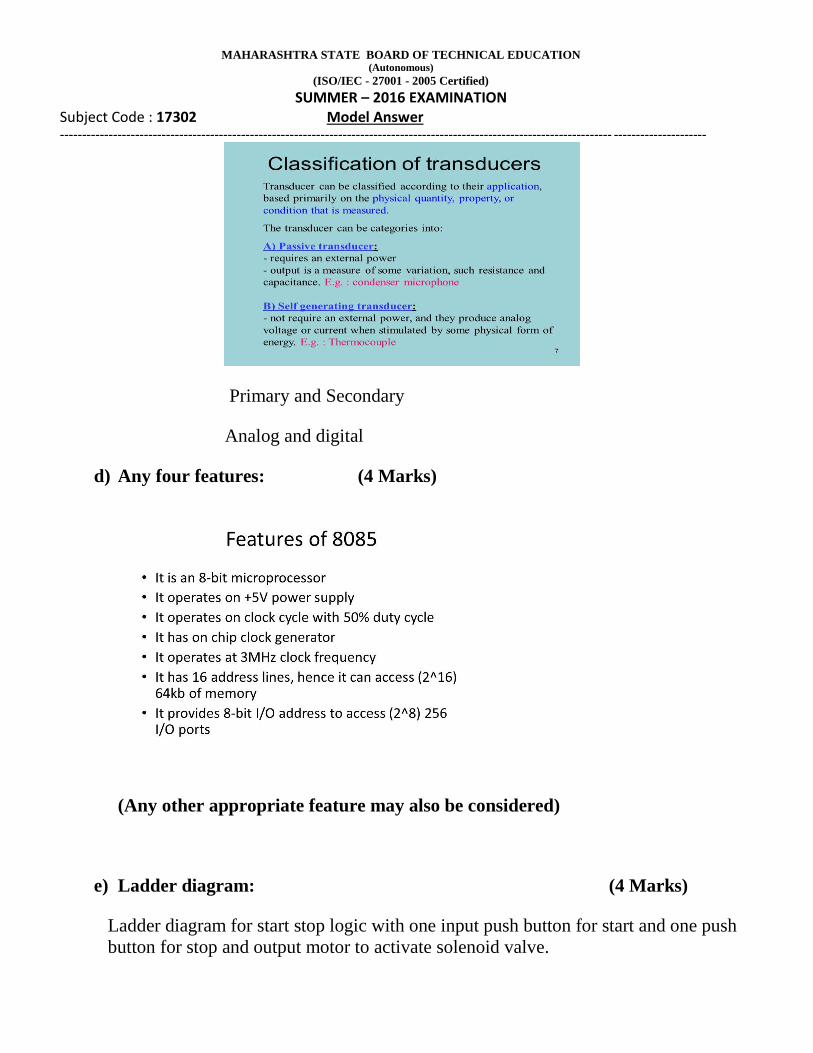
c) Transducer: (1 Mark)
A transducer is a device that converts one form of energy to another form.
Selection criteria: (2 Mark)
The following points should be considered, while selecting a transducer for any
application or a particular application.
Selection criteria for transducer: (Any four)
1. Type and nature of the physical quantity.
2. Accuracy of the transducer should be high.
3. Working principle of the transducer i.e. resistive, inductive, capacitive etc.
4. Transducer should have flat and stable frequency response.
5. Operating temperature of the transducer.
6. Transducer should have ability to withstand against shocks and vibrations
7. Transducer should not produce any loading effect on the next stages.
8. Transducers should have better linearity and stability.
9. Transducers should have high accuracy.
10. Transducers should not be affected by any type of noise and drift.
(Any other appropriate criterion may also be considered)
Classification: (1 Marks)
MAHARASHTRA STATE BOARD OF TECHNICAL EDUCATION (Autonomous)
(ISO/IEC - 27001 - 2005 Certified)
SUMMER – 2016 EXAMINATION Subject Code : 17302 Model Answer
----------------------------------------------------------------------------------------------------------------------------- ---------------------
Primary and Secondary
Analog and digital
d) Any four features: (4 Marks)
(Any other appropriate feature may also be considered)
e) Ladder diagram: (4 Marks)
Ladder diagram for start stop logic with one input push button for start and one push
button for stop and output motor to activate solenoid valve.

MAHARASHTRA STATE BOARD OF TECHNICAL EDUCATION (Autonomous)
(ISO/IEC - 27001 - 2005 Certified)
SUMMER – 2016 EXAMINATION Subject Code : 17302 Model Answer
----------------------------------------------------------------------------------------------------------------------------- --------------------- S1 – Stop button
S2 – Start button
S1 S2 M V M- motor
V- Solenoid valve
Students may draw different ladder diagram as per their logic, if logic is correct it may also be
considered.
f) D-Flip flop: (2+2Marks)
Logical diagram Truth Table
Question 5: Attempt any four: (16 Marks)
a) Load regulation ( 2 marks)
Load regulation is the capability to maintain a constant output voltage despite
changes in the supply's load current from no load to full load.
Line regulation ( 2 marks)
Line regulation is the change in the regulated load voltage due to change in line
voltage in a specified range of 230V ±10% at constant load current.
MAHARASHTRA STATE BOARD OF TECHNICAL EDUCATION (Autonomous)
(ISO/IEC - 27001 - 2005 Certified)
SUMMER – 2016 EXAMINATION Subject Code : 17302 Model Answer
----------------------------------------------------------------------------------------------------------------------------- ---------------------
% Line regulation = VLH – VLL/ Vnom * 100
b) Comparison of HWR and FWR : (4 Marks)
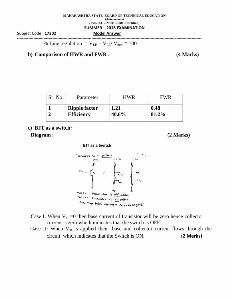
c) BJT as a switch:
Diagram : (2 Marks)
BJT as a Switch
Case I: When Vin =0 then base current of transistor will be zero hence collector
current is zero which indicates that the switch is OFF.
Case II: When Vin is applied then base and collector current flows through the
circuit which indicates that the Switch is ON. (2 Marks)
Sr. No. Parameter HWR FWR
1 Ripple factor 1.21 0.48
2 Efficiency 40.6% 81.2%

MAHARASHTRA STATE BOARD OF TECHNICAL EDUCATION (Autonomous)
(ISO/IEC - 27001 - 2005 Certified)
SUMMER – 2016 EXAMINATION Subject Code : 17302 Model Answer
----------------------------------------------------------------------------------------------------------------------------- ---------------------
d) Astable Multivibrator using IC 555:
Circuit diagram & waveforms (3+1 Marks)
e) Decade counter using T-Flip-flop:
Circuit Diagram: (2 Marks)
(For T-Flip-flop J=K=1)

MAHARASHTRA STATE BOARD OF TECHNICAL EDUCATION (Autonomous)
(ISO/IEC - 27001 - 2005 Certified)
SUMMER – 2016 EXAMINATION Subject Code : 17302 Model Answer
----------------------------------------------------------------------------------------------------------------------------- ---------------------
Truth Table: (2 Marks)
f) Reasons: (1 Mark)
Any two reasons:
Flexibility: Mechatronic product can be modified easily to fit changing
requirement and situation.
Multi functionality: Attributed to the software defined functions of the
microprocessor.
Intelligence related to the control functions of the mechatronic systems.
(Any other relevant reasons may also be considered.)

MAHARASHTRA STATE BOARD OF TECHNICAL EDUCATION (Autonomous)
(ISO/IEC - 27001 - 2005 Certified)
SUMMER – 2016 EXAMINATION Subject Code : 17302 Model Answer
----------------------------------------------------------------------------------------------------------------------------- ---------------------
Basic Elements of mechatronics: (3 Mark)
Actuators: Solenoid, voice coils, DC Motors, stepper motor, etc
Sensors: switches, MEMS, strain gauges, etc
Input signal conditioning & Interfacing: filters, amplifiers, ADC, DAC,etc
Output signal conditioning & Interfacing: filters, amplifiers, ADC, DAC,
PWM, etc
Graphical Display: LED, LCD, CRT, etc
Digital control Architecture: Logic ckts, uC, PLC, etc.
Question 6: Attempt any four: (16 Marks)
a) Block diagram of regulated power supply & functions of each block. (2+2 Marks)
Functions:
AC supply and transformer: A transformer changes the ac mains (line) voltage to a
required value. It is used to step the voltage up or down. Transformer provides isolation
from the power line.
Rectifier: A rectifier converts ac into pulsating dc. It may be a half-wave rectifier, a full-
wave rectifier using a transformer with centre-tapped secondary winding or a bridge
rectifier.

MAHARASHTRA STATE BOARD OF TECHNICAL EDUCATION (Autonomous)
(ISO/IEC - 27001 - 2005 Certified)
SUMMER – 2016 EXAMINATION Subject Code : 17302 Model Answer
----------------------------------------------------------------------------------------------------------------------------- ---------------------
Filter: A filter circuit is used remove ripple contents ( ac variations) from the rectified
voltage. There are four types of filters: 1) Capacitor filter, 2) Inductor filter, 3) L-C filter
and 4) π filter.
Voltage regulator: A voltage regulator is necessary to maintain a constant output dc
voltage by providing line regulation and load regulation.
b) PLC selection criteria: (4 Marks)
Any four
1. Number of inputs and number of outputs of PLC.
2. Nature of input and output i.e. Analog or Digital.
3. Speed of operation
4. Programming Flexibility
5. Power consumption.
6. Cost of PLC
{any other relevant and appropriate criteria may also considered}
c) Optocoupler as an Isolator: (4 Marks)
Optocoupler is a combination of light source and light detector in the same
package.
They are used to couple signal from one point to other optically by providing
complete electrical isolation between them.
This kind of isolation is provided between low power control circuit and high
power control circuit to protect the control circuit.
d) Single channel DAS:
Block diagram: (2 Marks)
MAHARASHTRA STATE BOARD OF TECHNICAL EDUCATION (Autonomous)
(ISO/IEC - 27001 - 2005 Certified)
SUMMER – 2016 EXAMINATION Subject Code : 17302 Model Answer
----------------------------------------------------------------------------------------------------------------------------- ---------------------
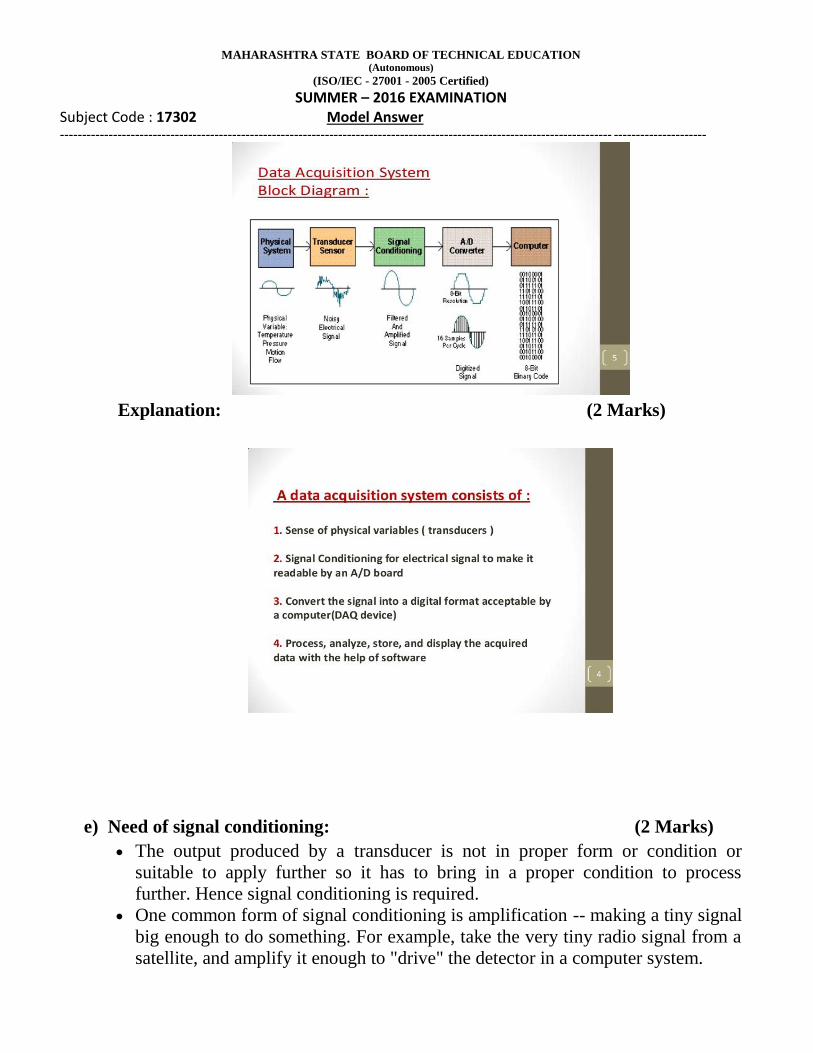
Explanation: (2 Marks)
e) Need of signal conditioning: (2 Marks)
The output produced by a transducer is not in proper form or condition or
suitable to apply further so it has to bring in a proper condition to process
further. Hence signal conditioning is required.
One common form of signal conditioning is amplification -- making a tiny signal
big enough to do something. For example, take the very tiny radio signal from a
satellite, and amplify it enough to "drive" the detector in a computer system.

MAHARASHTRA STATE BOARD OF TECHNICAL EDUCATION (Autonomous)
(ISO/IEC - 27001 - 2005 Certified)
SUMMER – 2016 EXAMINATION Subject Code : 17302 Model Answer
----------------------------------------------------------------------------------------------------------------------------- ---------------------
Buffering is another signal conditioning trick. In some electronic circuits their
very high impedance signals would be "loaded down" but attaching a voltmeter
or oscilloscope. So electronic voltmeters and scopes have Signal Buffers in them
to protect the signal from the "loading effects" of the meter or scope.
AC signal conditioning system: (2 Marks)
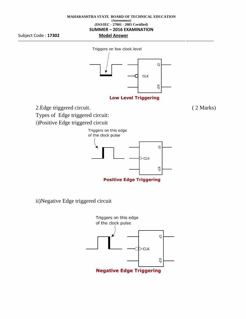
f)Triggering mechanism :
In the latches and flip flops, we use additional signal called Clock signal.
Depending on which portion of the Clock signal the latch or FF respond to, we can
classify them into two types:
1.Level triggered circuit (2 Mark)
Types of Level triggered circuit:
i)High/Positive Level triggered circuit
ii) Low/Negative Level triggered circuit
MAHARASHTRA STATE BOARD OF TECHNICAL EDUCATION (Autonomous)
(ISO/IEC - 27001 - 2005 Certified)
SUMMER – 2016 EXAMINATION Subject Code : 17302 Model Answer
----------------------------------------------------------------------------------------------------------------------------- ---------------------
2.Edge triggered circuit. ( 2 Marks)
Types of Edge triggered circuit:
i)Positive Edge triggered circuit
ii)Negative Edge triggered circuit

MAHARASHTRA STATE BOARD OF TECHNICAL EDUCATION (Autonomous)
(ISO/IEC - 27001 - 2005 Certified)
SUMMER – 2016 EXAMINATION Subject Code : 17302 Model Answer
----------------------------------------------------------------------------------------------------------------------------- ---------------------