magnetic drive pump md series instruction manual instruction manual.pdf · md series instruction...
TRANSCRIPT

Read this manual before use of product
MD SERIES
Instruction Manual
IWAKI Magnetic Drive Pump

Types of SymbolsIndicates that “Warning” or “Caution” must be exercised. Inside thistriangle, a concrete and practical image provided as a warning or cau-tion message is depicted.
Indicates a prohibited action or procedure. Inside or near this circle, aconcrete and practical image of the activity to be avoided is depicted.
Indicates an important action or procedure which must be performedor carried out without fail. Failure to follow the instructions hereincan lead to malfunction or damage to the pump.
Thank you for having selected the Iwaki Magnetic Drive PumpMD series. This manual deals with the correct handling andoperation procedures and troubleshooting methods for thepump. To make maximum use of the pump and to ensure safe,long operation, please read this manual carefully prior tooperating the pump. Pay special attention to the “Warning” and“Caution” sections as they relate to matters of safety andproper usage of the pump.
Nonobservance or misapplication of thecontents of the “Caution” section couldlead to serious physical injury to the user orserious damage to the product.
WarningNonobservance or misapplication of thecontents of the “Warning” section couldlead to a serious accident, including deathor injury.
Caution
Important Instruction
ContentsChapter Page
1. Safety Instruction ···································································· 1, 2
2. Unpacking and Inspection ·························································· 3
3. Operating Principle ····································································· 3
4. Identification Codes ································································ 4, 5
5. Specifications ········································································· 6, 7
6. Outer Dimensions and Performance Curve························· 8 ~ 13
7. Main Parts and Label ································································ 14
8. Name of Parts ············································································ 15
9. Handling ··········································································· 16 ~ 18
10. Installation, Piping, and Wiring ······································· 19 ~ 23
11. Operation ·········································································· 24 ~ 26
12. Causes of Trouble and Troubleshooting ··································· 27
13. Maintenance/inspection and consumable parts ························ 28
For the Safe and Correct Handling of the Pump
• Read the “Safety Instructions” sections carefully to prevent acci-dents involving your customers or other personnel and to avoiddamage or loss of other assets. Always follow the instructions andadvice found in these sections.
• Observe and abide by the instructions described in this manual.These instructions are very important for protecting pump usersfrom dangerous conditions and situations related with the use of thepump system.
• The symbols relate to the following meanings described below:
- 1 -
1. Safety Instruction
Warning Caution
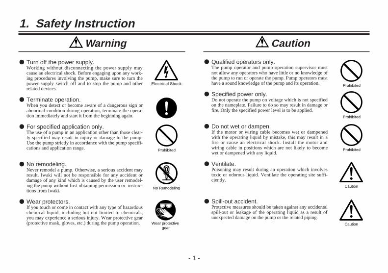
● Turn off the power supply.Working without disconnecting the power supply maycause an electrical shock. Before engaging upon any work-ing procedures involving the pump, make sure to turn thepower supply switch off and to stop the pump and otherrelated devices.
● Terminate operation.When you detect or become aware of a dangerous sign orabnormal condition during operation, terminate the opera-tion immediately and start it from the beginning again.
● For specified application only.The use of a pump in an application other than those clear-ly specified may result in injury or damage to the pump.Use the pump strictly in accordance with the pump specifi-cations and application range.
● No remodeling.Never remodel a pump. Otherwise, a serious accident mayresult. Iwaki will not be responsible for any accident ordamage of any kind which is caused by the user remodel-ing the pump without first obtaining permission or instruc-tions from Iwaki.
● Wear protectors.If you touch or come in contact with any type of hazardouschemical liquid, including but not limited to chemicals,you may experience a serious injury. Wear protective gear(protective mask, gloves, etc.) during the pump operation.
Electrical Shock
Prohibited
No Remodeling
Wear protective gear
● Qualified operators only.The pump operator and pump operation supervisor mustnot allow any operators who have little or no knowledge ofthe pump to run or operate the pump. Pump operators musthave a sound knowledge of the pump and its operation.
● Specified power only.Do not operate the pump on voltage which is not specifiedon the nameplate. Failure to do so may result in damage orfire. Only the specified power level is to be applied.
● Do not wet or dampen.If the motor or wiring cable becomes wet or dampenedwith the operating liquid by mistake, this may result in afire or cause an electrical shock. Install the motor andwiring cable in positions which are not likely to becomewet or dampened with any liquid.
● Ventilate.Poisoning may result during an operation which involvestoxic or odorous liquid. Ventilate the operating site suffi-ciently.
● Spill-out accident.Protective measures should be taken against any accidentalspill-out or leakage of the operating liquid as a result ofunexpected damage on the pump or the related piping.
Prohibited
Prohibited
Prohibited
Caution
Caution

- 2 -
● Operating site must be free of water andhumidity.The pump is not designed to be water-proof or dust-proof.The use of the pump in places where water splashes orhumidity is high may result in an electrical shock or shortcircuit.
● Do not damage power cable.Do not scratch, damage, process, or pull the power cableforcibly. An extra load onto the cable, such as heating thecable or placing something heavy on the cable, may dam-age the cable and finally cause a fire or an electrical shock.
● Do not cover the motor.Running a covered motor may accumulate heat inside themotor and cause a fire or a mechanical failure. Ventilatethe motor sufficiently.
● Arrange grounding.Do not operate the pump without connecting the groundingwire. Otherwise, an electrical shock may result. Make surethe grounding wire is connected with the grounding termi-nal.
● Install an earth leakage breaker (option).The operation of a pump without using an earth leakagebreaker may cause an electrical shock. Please purchase anoptional leakage breaker and install in the system.
Prohibited
● Power cable cannot be replaced.Never use a damaged or affected power cable. Otherwise,a fire or an electrical shock may result. Handle the powercable carefully, as it cannot to be replaced by a new cable.(The complete motor must be replaced in that circum-stance.)
● Limited operating site and storage.Do not install or store the pump in the following places:* Places where a flammable gas or material is used or
stored.* Places where the ambient temperature is extremely high
(40°C or higher) or extremely low (0°C or lower).
● Do not drain the liquid in the site.The liquid discharged out of the pump, including a haz-ardous chemical liquid, must be drained into a special con-tainer. Never drain such liquid directly onto the floor in ornear the operation site.
● Disposal of used pump.Disposal of used or damaged pumps must be done inaccordance with the relevant local laws and regulations.(Consult a licensed industrial waste products disposingcompany.)
● Countermeasure for static electricity.When low electric conductivity liquid such as ultra-purewater and flour inactive liquid(e.g.FluorinertTM) are han-dled,the static electricity may be generated in pump,whichmay cause static discharge and break down of pump. Takecountermeasure to avoid and remove static electricity.
Caution
Grounding
Electrical Shock
Caution
Prohibited
Prohibited
Caution Caution

- 3 -
2. Unpacking and Inspection 3. Operating Principle
[1] Do the model, flow and headindicated on the nameplatecorrespond with your order?
[2] Has the pump or any part of itbeen damaged as a result ofaccident or handling duringshipment?
The centrifugal pump is driven by pair of magnets which areincorporated in the impeller and motor shaft. The sealless pumpstructure eliminates shaft seals such as conventional mechanical sealsbecause the pump chamber is shielded by the casings and the impelleris operated by the magnets. The combined coupling torque of thedrive magnet and impeller magnet gives sufficient driving poweragainst the motor torque.
Impeller
Suction
Discharge
Drive magnet
Driven magnet
Spindle
After unpacking the product, check the following points.
If you find any discrepancy, please contact your dealer.

- 4 -
4. Identification Codes
q w r t y u ie
1 Series type MD-15R, MD-20R, MD-30R, MD-40R
2 Pump typeX: High flow rate type Z: High head typeNo symbol: Standard type
3 Pump head materialV: PVDF (Note)No symbol: Polypropylene
4 Suction/discharge port type
M: Threaded connection5M: Threaded connection, For 50Hz of MD-40RZ model only5: Hose connection, For 50Hz of MD-40RZ model onlyNo symbol: Hose connection
5 Power source voltage 220: 220/240V(50/60Hz) 230: 230V (50/60Hz)
6 O ring material E: EPDM No symbol: FKM
7 Motor type N: New type motor
8 Special design code01~99: Special design codeNo symbol: Standard model
Note: PVDF pump head material (V type) is available for models MD-15R, 20RZ, 30R and 30RZ.

- 5 -
q w r te
1 Series type MD-55R, MD-70R, MD-100R
3 Pump head materialV: PVDF (Note)No symbol: Polypropylene
4 Suction/discharge port type
M: Threaded connection, For 50/60Hz5M: Threaded connection, For 50Hz of 55R and 100R models only5: Hose connection, For 50Hz of MD-55R and 100R models onlyNo symbol: Hose connection, For 50/60Hz
5 Special design code01~99: Special design codeNo symbol: Standard model
2 Pump type Z: High head type No symbol: Standard type
Note: PVDF pump head material (V type) is available for models MD-70R and 70RZ.

220/240Single-phase
- 6 -
5. Specifications
ModelPort size (mm) Threaded connection Max.
flow rate(l/min)
Max. head(m)
Max.specificgravityof liquid
MotorMass(kg)Suction
portDischarge
portSuction/
DischargeUnion
(see P13)Power source
voltage (V)Rated
output (W)
MD-15R 14 14G 3/4
13 16/19 2.4/3.4 1.3
220/240Single-phase
10 1.6
MD-20R 18 18 16 27/31 3.1/4.3 1.1
20 2.0MD-20RX 26 26 G1 20 46/52 1.8/2.5 1.3
MD-20RZ 18 18G 3/4
13 10/11 4.9/6.9 1.1
MD-30R 20 20 16 32/38 3.8/5.4 1.3
45 4.0MD-30RX 26 26 G1 20 62/72 2.9/4.1 1.1
MD-30RZ 18 18G 3/4
13 15/17 8/11 1.0
MD-40R 20 20 16 45/52 4.6/6.5 1.1
65 3.9MD-40RX 26 26 G1 20 75/85 3.3/4.7 1.1
MD-40RZ 20 20G 3/4
16 22/22 10/13.5 1.0
MD-40RZ-5 20 20 16 11/ – 11.5/ – 1.0
MD-55R26 26 G1 20
60/70 5.6/8.2 1.290 5.4
MD-55R-5 70/ – 8.2/ – 1.2
50/60Hz

- 7 -
ModelPort size (mm) Threaded connection Max.
flow rate(l/min)
Max. head(m)
Max.specificgravityof liquid
MotorMass(kg)Suction
portDischarge
portSuction/
DischargeUnion
(see P13)Power source
voltage (V)Rated
output (W)
MD-70R 26 26 G1 20 86/97 6.7/9.7 1.0 220/240Single-phase
or220/3803-phase400/4403-phase
150/180 6.0
MD-70RZ 20 20 16 40/43 14.3/20.3 1.0 180/216 6.0
MD-100R26 26 G1 20
120/135 8.6/11.9 1.2
MD-100R-5 135/ – 11.7/ – 1.1260/265 8.5
G 3/4
Note:
1. Pump performance data is based on pumping clean water atamb. temp.
2. The maximum flow rate is at 0 discharge head.
3. Maximum viscosity of liquid: 0.03 Pa•s (for a specific gravityof 1.0)
4. Permissible liquid temperature: 0~80°C(When IWAKI option union is used, the liquid temp. is limitedto 0~55°C. Also, the permissible temperature may differdepending upon the type of liquid and operating conditions.)
5. The maximum specific gravity of the liquid is the value atmax. flow rate. The value varies depending on the flow rate,ambient temperature, viscosity of liquid, etc.
6. Motor: Single-phase capacitor-run induction motor or 3-phase induction motor.* Built-in thermal protector
A thermal protector is built in the motor. The protectorautomatically stops motor operation when the motor isoverheated. (The motor starts again when the temperaturefalls to normal.)
7. Same performance is kept between threaded and hoseconnection types and also between PVDF and Polypropylenematerial types.
50/60Hz

- 8 -
6. Outer Dimensions and Performance Curve
■ Outer dimensions• MD-15RM, 20RM, 30RM and 40RM types
Le
ab
G
cW
dH
f
Le
ab
G
cW
dH
f
Model W H L a b c d e f GMD-15RM 95 114 179 – 50 68 55 39 21.5 117MD-20RM 85 116 203 30 50 68 55 33 28.5 126MD-30RM 120 130 248 40 64 100 60 48 31 169MD-40RM 120 130 250 40 64 100 60 48 31 169
• MD-20RXM, 30RXM and 40RXM typesL
e
ab
G
cW
dH
Model W H L a b c d e GMD-20RXM 85 132 220 30 50 68 55 46.5 143MD-30RXM 120 140 254 40 64 100 60 50 175MD-40RXM 120 141 256 40 64 100 60 50 175
• MD-15R, 20R, 30R and 40R types
Model W H L a b c d e f GMD-15R 95 109 179.5 – 50 68 55 39 21.5 117MD-20R 85 115 208.5 30 50 68 55 38.5 28.5 131.5MD-30R 120 130 248 40 64 100 60 48 31 169MD-40R 120 130 250 40 64 100 60 48 31 169

- 9 -
28.5
126
• MD-20RX, 30RX, and 40RX typesL
e
ab
G
cW
dH
Model W H L a b c d e GMD-20RX 85 132 220 30 50 68 55 46.5 143MD-30RX 120 137 254 40 64 100 60 50 175MD-40RX 120 137 256 40 64 100 60 50 175
• MD-20RZ, 30RZ, 40RZ and 40RZ-5 typesL
e
G
cW
f
dH
ab
• MD-55R and 55R-5 typesL
e
ab G
cW
dH
f
Model W H L a b c d e f GMD-55R
120 155 273.5 40 64 100 65 61.5 198.5MD-55R-5
40
• MD-20RZM, 30RZM, 40RZM and 40RZ-5M typesL
e
ab
G
cW
dH
f
Model W H L a b c d e f GMD-20RZM 85 125 211 30 50 68 55
39.5 38.5134
MD-30RZM 120 130 230 40 64 100 60 152MD-40RZM 120 150 241 40 64 100 60 38.5 44.5 160MD-40RZ-5M 120 150 241 40 64 100 60 38.5 44.5 160
Model W H L a b c d e f GMD-20RZ 85 125 211 30 50 68 55
39.5 38.5134
MD-30RZ 120 130 230 40 64 100 60 152MD-40RZ 120 150 241 40 64 100 60 38.5 44.5 160MD-40RZ-5 120 150 241 40 64 100 60 38.5 44.5 160
169
- 10 -
• MD-55RM and 55R-5M typesL
e
ab
G
cW
dH
f
Model W H L a b c d e f GMD-55RM
120 155 273.5 40 64 100 65 61.5 198.5MD-55R-5M
40
• MD-70R, 70RZ, 100R and 100R-5 typesL
e
ab
G
cW
dH
f
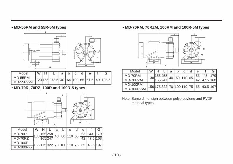
Model W H L a b c d e f GMD-70R
130155 258
40 60 110 6553 43 179
MD-70RZ 165 247 42 47.5 168MD-100R
156 175 322 70 100 110 75 65 43.5 197MD-100R-5
• MD-70RM, 70RZM, 100RM and 100R-5M typesL
e
ab
G
cW
dH
f
Model W H L a b c d e f GMD-70RM
130155 258
40 60 110 6553 43 179
MD-70RZM 165 247 42 47.5 168MD-100RM
156 175 322 70 100 110 75 65 43.5 197MD-100R-5M
Note: Same dimension between polypropylene and PVDFmaterial types.

- 11 -
■ Standard Performance Curve(Pumping clean water at room temperature)
m
11
10
9
8
7
6
5
4
3
2
1
1 2 3 4 5 10 20 30 40 50 100 150 200:min
100R-5
55R-5
100R30RZ
20RZ 55R
70R
40R
20R 30R 40RX15R
20RX 30RX
m
11
10
9
8
7
6
5
4
3
2
1
1 2 3 4 5 10 20 30 40 50 100 150 200:min
100R
55R
70R
40R
20R
30R15R
30RX
30RZ
20RZ
20RX
40RX
Note: Same performance between threaded and hoseconnection types and also between PVDF andPolypropylene types.
- 12 -
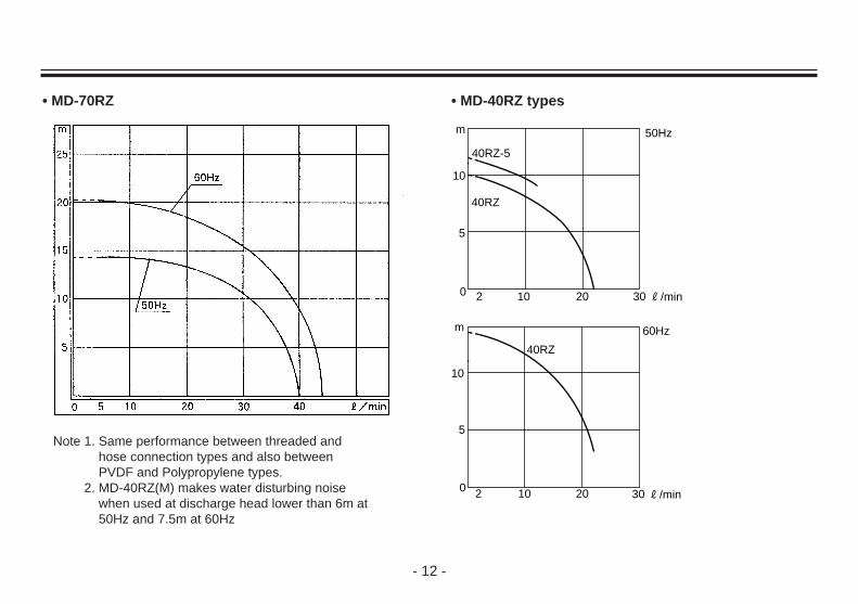
• MD-70RZ • MD-40RZ types
10
5
10 20 300
40RZ
40RZ-5
50Hzm
R/min2
10
5
10 20 300
60Hz
40RZ
m
R/min2
Note 1. Same performance between threaded andhose connection types and also betweenPVDF and Polypropylene types.
2. MD-40RZ(M) makes water disturbing noisewhen used at discharge head lower than 6m at50Hz and 7.5m at 60Hz

- 13 -
■ Special accessoriesThe following union insets are available as components for piping.
ModelConnecting port
screw sizeApplicable
O-ringApplicable union(Port diameter)
MD-15RMG3/4
AS-568-016 13A
MD-20RM AS-568-017 16A
MD-20RXM G1 AS-568-020 20A
MD-20RZMG3/4
AS-568-016 13A
MD-30RM AS-568-017 16A
MD-30RXM G1 AS-568-020 20A
MD-30RZMG3/4
AS-568-016 13A
MD-40RM AS-568-017 16A
MD-40RXM G1 AS-568-020 20A
MD-40RZMG3/4 AS-568-017 16A
MD-40RZ-5M
MD-55RM
G1 AS-568-020 20AMD-55RM-5M
MD-70RM
MD-70RZM G3/4 AS-568-017 16A
MD-100RMG1 AS-568-020 20A
MD-100RM-5M
Note: PVDF material is not available for union.

- 14 -
7. Main Parts and Label
Motor (Driving unit)Install the pump at the plate where the liquidcan not be splashed.
Pump unit (Liquid feeding unit)
Discharge port
Suction port
BaseFix the pump securely.
Specifications labelUse the pump by observing the specificationsdescribed on the label.
- 15 -
8. Name of Parts
52789
1
3
6
4
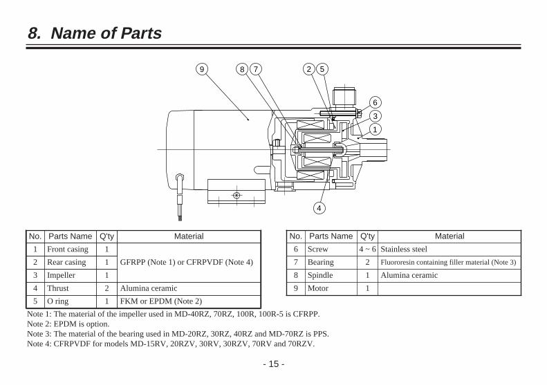
No. Parts Name Q'ty Material
1 Front casing 1
GFRPP (Note 1) or CFRPVDF (Note 4)2 Rear casing 1
3 Impeller 1
4 Thrust 2 Alumina ceramic
5 O ring 1 FKM or EPDM (Note 2)
No. Parts Name Q'ty Material
6 Screw 4 ~ 6 Stainless steel
7 Bearing 2 Fluororesin containing filler material (Note 3)
8 Spindle 1 Alumina ceramic
9 Motor 1
Note 1: The material of the impeller used in MD-40RZ, 70RZ, 100R, 100R-5 is CFRPP.Note 2: EPDM is option.Note 3: The material of the bearing used in MD-20RZ, 30RZ, 40RZ and MD-70RZ is PPS.Note 4: CFRPVDF for models MD-15RV, 20RZV, 30RV, 30RZV, 70RV and 70RZV.
- 16 -
9. Handling
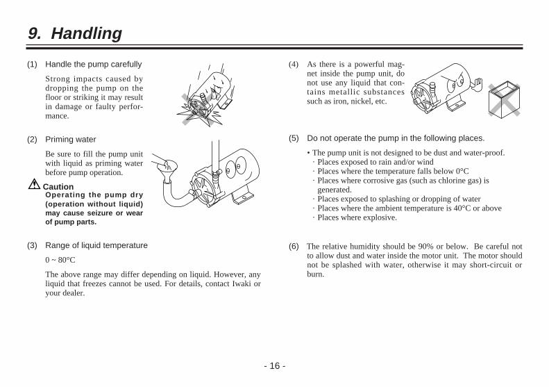
(1) Handle the pump carefully
Strong impacts caused bydropping the pump on thefloor or striking it may resultin damage or faulty perfor-mance.
(2) Priming water
Be sure to fill the pump unitwith liquid as priming waterbefore pump operation.
CautionOperating the pump dry(operation without liquid)may cause seizure or wearof pump parts.
(5) Do not operate the pump in the following places.
• The pump unit is not designed to be dust and water-proof.· Places exposed to rain and/or wind· Places where the temperature falls below 0°C · Places where corrosive gas (such as chlorine gas) is
generated.· Places exposed to splashing or dropping of water· Places where the ambient temperature is 40°C or above· Places where explosive.
(6) The relative humidity should be 90% or below. Be careful notto allow dust and water inside the motor unit. The motor shouldnot be splashed with water, otherwise it may short-circuit orburn.
(4) As there is a powerful mag-net inside the pump unit, donot use any liquid that con-tains metallic substancessuch as iron, nickel, etc.
(3) Range of liquid temperature
0 ~ 80°C
The above range may differ depending on liquid. However, anyliquid that freezes cannot be used. For details, contact Iwaki oryour dealer.

- 17 -
(7) Do not operate the pump with the following liquids.
• For the compatibility to chemical liquid or any special liquid,contact IWAKI sales representative.
• Liquids that significantly swell polypropylene
· Paraffinic hydrocarbons such as gasoline and kerosene · Halogenated hydrocarbons such as trichloroethylene and
carbon tetrachloride · Ether and low-grade ester
• Slurry(Never use slurry, which wears out the pump bearing.)
(8) Keep the pump away fromfire.
To prevent fire and explo-sions, do not place danger-ous or inflammable sub-stances near the pump.
(9) Grounding
Be sure to connect thegrounding cable (green/yel-low). In addition, arrange anearth leakage breaker to pre-vent electrical shocks.
(10) If pump is damaged
Do not operate a damagedpump, otherwise there mayhappen the electricity leak-age or electric shocks.
(11) Surface temperature
The surface temperature ofthe motor or the pump maybe extremely high during thepump operation.Do not touch it directly.
Caution

- 18 -
(12) Sound generated by pump
The level of sound generated by the pump is shown in the table.
(dB)
*When measured at a distance of 1m A scale
Model Sound *Level Model Sound *
Level
MD-15R 40MD-30RXMD-30RZMD-40RMD-40RXMD-40RZ
60
MD-20R 45
MD-20RXMD-20RZ 50
MD-55R 55
MD-70RMD-70RZ 70
MD-30R 55 MD-100R 75

- 19 -
10. Installation, Piping and Wiring
10-1. Installation(1) Installation site
An installation site must be an ambient temperature of 0~40°Cand a relative humidity of lower than 90%. Install the pump at theplace where the maintenance and inspection work can be doneeasily.
(2) Pump installation method
This pump is not the selfprim-ing pump. The pump shall beinstalled in a position lowerthan the liquid level of thesuction tank.Liquid level must be higher by30 cm than the pump suctionport level. If this distance istoo short, the air may besucked in the pump, whichwill cause abnormal wear ofpump bearing.
(3) Direction of pumpdischarge port
The discharge port can bedirected as desired. However,for efficient elimination of theair out of the pump chamber,it is recommended that the dis-charge port is directedupward.
(4) Anchoring of base
The base of the pump must beanchored firmly.
The pump must not be mount-ed in a vertical position.
(5) Hose preparation
The ends of the hoses shouldbe cut flat before connectingthem.

- 20 -
10-2. PipingPiping instructions
(1) To minimize the friction resistance, the shortest piping possiblewith the minimum number of bends should be utilized. Especiallyfor suction piping, employ as larger and shorter hose as possible.
(2) Use a corrosion-resistant vinyl hose that can endure the pressuremade by the pump operation.
If the connection on the suction side is inadequate, air may bemixed in.
(3) Hose size
Select a hose in accordance with the diameter of the pump port.A reliable connection is not guaranteed if different size of hose isused.
As the hose on the suction side, in particular, tends to be crushedunder the sucking force, the use of a braided hose is recommend-ed. (In the case of hot liquid feeding, special attention must bepaid in the selection of a hose.)
(4) Valve installation
Install valves close to the suc-tion and discharge port.
· Suction side valve: For easy removal or mainte-nance of the pump.
· Discharge side valve:For adjustment of the dis-charge rate or head.
(5) Hose connection
Press the hose end firmlyagainst the discharge or suc-tion port until it reaches thebottom of the port.
*Use a fastener (such as ahose band) to make the con-nection firm and free of liq-uid leakage.
CautionDo not tighten the connec-tion ports (suction and dis-charge) excessively as theyare made of plastic resinand are easily damaged.

- 21 -
10-3. Wiring(1) Prior to wiring work, check the voltage specified on the name-
plate.
Use specified wiring materials. (Observe the local regulationsrelated with electrical work.) The connection diagram and thetable showing the rated current and starting current for eachmodel are presented below.
(2) Do not fail to connect a ground wire (green/yellow).
(3) The pump has no On/Off switch. It starts operation when power issupplied by connecting the power supply cable or other means.
■ Wiring diagram
• MD-15R, 20R, 20RX, 20RZ, 30R, 30RX and 30RZ(Single-phase capacitor run motor with thermal protector)
Brown
Blue
Yellow/Green
Thermal protector
Power sourceAuxiliary coil
Capacitor
Main coil
• MD-40R, 40RX, 40RZ, 40RZ-5, 55R, 55R-5, 70R, 70RZ,100R and 100R-5(Single-phase capacitor run motor with thermal protector)
Brown
Blue
Yellow/Green
Thermal protector
Power source
Auxiliary coil
CapacitorMain coil

- 22 -
• MD-70R, 100R, 70RZ and 100R-5 models(3-phase motor,400/440V)
• MD-70R, 100R, 70RZ and 100R-5 models (3-phase motor, 220/380V)
Thermal protector
Thermal protector
Thermal protector
Thermal protector
Powersauce
Powersauce
Rotor
(220V)
(380V)
Red
Gray
W2
U1
White
Blue
U2
V1
Black
Yellow
V2
W1
Red
Gray
W2
U1
White
Blue
U2
V1
Black
Yellow
V2
W1
Thermal protector
Thermal protector
Powersauce Rotor

- 23 -
■ Rated Current and Starting Current (50/60Hz)
ModelRated current (50/60Hz) (Amp.) Starting current (50/60Hz) (Amp.)
220/240V(Single-phase)
220/380V(3-phase)
400/440V(3-phase)
MD-15R
MD-20R
MD-20RX
MD-20RZ
MD-30R
MD-30RX
MD-30RZ
MD-40R
MD-40RX
MD-40RZ
MD-40RZ-5
MD-55R
MD-55R-5
MD-70R
0.19 / 0.18
0.24 / 0.28
0.24 / 0.29
0.24 / 0.29
0.4 / 0.5
0.42 / 0.5
0.52 / 0.7
0.46 / 0.58
0.4 / 0.5
220/240V(Single-phase)
220/380V(3-phase)
400/440V(3-phase)
0.3 / 0.29
0.4 / 0.4
0.4 / 0.4
0.4 / 0.4
1.2 / 1.25
1.2 / 1.25
1.1 / 1.0
1.1 / 1.0
1.2 / 1.25
MD-70RZ
MD-100R
MD-100R-5
1.2/
0.7
1.3/
0.8
1.18/
0.69
1.17/
0.87
1.15/
0.64
1.3/
0.69
3.8/
4.3
3.6/
4.0
3.15/
3.55
2.9/
3.2
3.15/
3.42
2.95/
3.15
4.15/
2.45
4.0/
2.4
3.8/
2.2
3.7/
2.1
3.9/
2.25
3.8/
2.2
2.15/
2.3
2.05/
2.27
1.9/
2.2
1.85/
2.1
1.24/
2.27
1.22/
1.25
– –
1.93/
1.93
1.85/
1.83
1.21/
1.21
1.64/
1.50
1.93/
1.93–
1.18/
0.69
0.62/
0.6
0.62/
0.6
0.6/
0.58
0.39/
0.4
0.46/
0.45
–1.9/
2.2–
3.8/
2.2–
3.8/
4.3
0.65 / 0.85
0.65 / –
1.25 / 1.35
1.25 / –
0.8 / 0.9
1.0 / –
2.3 / 2.1
2.3 / 2.1
1.4 / 1.9 0.6 / 0.7

- 24 -
11. Operation
Caution
• Before operating the pump, confirm that the hoses con-nected with the discharge port and suction port are firmlyfixed in position.
• Dry operation (operation without liquid in the pump) dam-ages the pump. Be sure to fill the pump with priming liquidin advance.
• Do not keep on operating the pump with entirely or almostclosed discharge or/and suction side valve(s).
• Do not open or close the suction or discharge side valvesuddenly, otherwise the magnet coupling may bedetached, disabling the rotation of the impeller. (Undersuch circumstances, turn off the power supply. When themotor stops rotating, the coupling will be connected.)
■ Operation instructions
No.
1
2
3
4
Operation Step
Check piping, wiringand voltage.
Open and closevalves.
Check that pumpchamber is filledwith liquid.
Supply power topump
Description (Points to be Checked)
Check in accordance with the 'Hoseconnection' and 'Wiring' sections.Check the power supply voltage byreferring to the information on thenameplate.
• Fully open suction side valve.
• Fully close discharge side valve.
• Fill pump chamber with primingwater (feeding liquid).
Carry out sufficient priming in case ofsuction lift method.
After steps 1 to 3 above, connectpower supply to start pump.
■ Operation
After the installation, piping and wiring processes are completed,operate the pump in accordance with the following steps.

- 25 -
No.
5
6
Operation Step
Adjust dischargecapacity & head todesired values.
Checkpoints duringoperation
Description (Points to be Checked)
Adjust discharge side valve graduallytill desired discharge capacity and headare obtained. Do not open or closevalves suddenly.Note: Do not keep discharge side
valve closed for more than 1minute.
Note: Check that pump feeds liquidnormally. If not, turn off powerimmediately and eliminatecause referring to 'Causes ofTrouble and Troubleshooting'section (p.27).
• Be careful to prevent foreign matterfrom entering pump. Foreign matterin pump may cause impeller to belocked, hindering liquid circulation.Motor itself continues to rotate evenif impeller is locked. In such a case,turn off power supply at once.
• When earth leakage breaker is acti-vated, turn off power supply at onceand eliminate cause by referring to'Causes of Trouble andTroubleshooting' section.
No.
1
2
Stopping Step
Close discharge sidevalve.
Turn off powersupply. (Checkstopping condition.)
Description
Close discharge side valve gradually.Do not use electromagnetic valve forquick closing.
Check that motor stops smoothly afterpower supply is disconnected. If not,pump should be inspected. (Fordetails, contact Iwaki or your dealer.)
■ Pump Stopping Procedure
■ How to store pump when it is out of use for a long time
Remove the liquid from the pump if it is to be stored for a longtime. In addition, run it with water circulating for about 5 min-utes every 3 months to prevent rust on the motor bearing.
- 26 -
Draining Method
Warning• Before starting the draining procedure, turn off the power supply.
• Be sure to wear proper safety gear (gloves, protective shoes,etc.) during draining work. When chemical liquid is used, wearrubber gloves, goggles).
Caution• Pay special attention to the remaining liquid which may run out of
the discharge port or the suction port when removing the hose.Pay attention not to allow the motor or electric parts to come intocontact with the liquid.
• Never discharge hazardous or chemical liquid over the ground orfloor in the plant. Instead, use a draining pan (or container).Observe each applicable local law or regulation for the handlingor disposal of hazardous liquids.
Draining procedure:
(1) Turn off the power supply. (Make sure no other operator will turn on the power supply acci-dentally.)
(2) Close the discharge and suction sides valves fully.
(3) Remove the hoses connected with the discharge port andthe suction port.Position the draining pan below the pump unit in advance.Loosen the hose band and rotate the hose clockwise and counter-clockwise slowly to completely pull the hose off of each port.(Liquid will run out when the hose is disconnected.)
(4) Remove the screws on the pump base to detach the pumpunit.
(5) Direct the discharge port downward to drain the liquid intothe draining pan.Never discharge hazardous liquid, over the ground or the floorinside the plant. Use a draining pan (or container).

- 27 -
12. Causes of Trouble and Troubleshooting
TroubleshootingCause
Trouble Pump does not
start.
Pumping is not done or insufficient.
Electric current is too high.
Excessive noise or vibration.
Liquid leaks.
Power is not supplied or wiring is faulty.
Motor is out of order (disconnected coil or capacitor failure).
There is residual air in the pump.
Air is sucked in via suction port.
Pump is driven dry.
Specific gravity/viscosity of liquid is too high.
Periphery of impeller magnet is in contact with rear casing.
Impeller is damaged.
Foreign matter adheres to impeller.
O ring is damaged.
Loosened front casing fixing bolts.
Supply power or contact your dealer.
Contact your dealer.
Eliminate air completely.
Fasten hose tightly.
Supply priming water to pump.
Use suitable type of pump.
Contact your dealer.
Contact your dealer.
Tighten bolts.
Contact your dealer.
Contact your dealer.
K
K
K
K
K
K
K
K
K
K
K
K
K
K
K
K
K
K
K
K
K
K
K
K
K
K
K

13. Maintenance/inspection and consumable parts
- 28 -
Warning• Turn off power when works is done. Wear glove and safety
shoes or so when you do maintenance works.
• When dangerous or chemical liquid is handled, you must be pro-tected by rubber glove and goggle or so.
Caution• When you remove hose from pump, pay attention to liquid inside
pump going out from discharge and suction port. Pay attentionfor liquid not to splash on motor or electrical part. Motor is notdust and water proof construction.
• Dangerous or chemical liquid must not be drained directly on theground but drained to receiving plate or vessel. Follow local lawsor regulation for handling of dangerous liquid or chemicals.
■ Maintenance and inspection
• When pump has been used for a long time, pump headtightening screws may have been loosened. Tighten screwswith tightening torque not deforming plastic parts. Whenpump is stored for a long time, too, tighten screws beforepump is used.
• Daily inspectionCheck operating conditions (vibration, noise) and also checkelectric current value and pump discharge capacity. As soonas you find any abnormality, turn off power and remove thecause referring to “Troubleshooting” on page 27.
■ Consumable parts
• Consumable parts shown below must be replaced withinindicated replacement time. Replacement time shown belowis based on pumping clear water at ambient temperature andit is influenced by characteristics and temperature of handledliquid and also influenced if liquid contains slurries (solidsubstance).
• Damage or loss caused by corrosion by liquid or wear byslurries are not guaranteed.
• Replace O ring every time when pump is disassembledregardless of replacement time shown below.
No. Parts Replacement time
2 Front casing unit
10,000 hours
3 O ring
4 Impeller unit
5 Rear casing unit
7 Motor

T385-2 ’04/01
TEL:(81)3 3254 2935 FAX:3 3252 8892(http://www.iwakipumps.jp)
U.S.A.
Australia
Singapore
Indonesia
Malaysia
Taiwan
Thailand
Hong Kong
China
China
China
China
Philippines
Korea
: IWAKI WALCHEM Corporation
: IWAKI Pumps Australia Pty. Ltd.
: IWAKI Singapore Pte. Ltd.
: IWAKI Singapore (Indonesia Branch)
: IWAKIm Sdn. Bhd.
: IWAKI Pumps Taiwan Co., Ltd.
: IWAKI (Thailand) Co.,Ltd.
: IWAKI Pumps Co., Ltd.
: IWAKI Pumps (Guandong) Co., Ltd.
: GFTZ IWAKI Engineering & Trading (Guangzhou)
: IWAKI Pumps Co., Ltd. (Beijing)
: IWAKI Pumps (Shanghai) Co., Ltd.
: IWAKI Chemical Pumps Philippines, Inc.
: IWAKI Korea Co.,Ltd.
FAX : 508 429 1386
FAX : 2 9899 2421
FAX : 6763 2372
FAX : 21 690 6612
FAX : 3 7803 4800
FAX : 2 8227 6818
FAX : 2 322 2477
FAX : 2 607 1000
FAX : 750 380 9078
FAX : 20 8435 9181
FAX : 10 6442 7712
FAX : 21 6272 6929
FAX : 2 843 3096
FAX : 2 3474 0221
TEL : (1)508 429 1440
TEL : (61)2 9899 2411
TEL : (65)6763 2744
TEL : (62)21 690 6606
TEL : (60)3 7803 8807
TEL : (886)2 8227 6900
TEL : (66)2 322 2471
TEL : (852)2 607 1168
TEL : (86)750 380 9018
TEL : (86)20 8435 0603
TEL : (86)10 6442 7713
TEL : (86)21 6272 7502
TEL : (63)2 888 0245
TEL : (82)2 3474 0523
FAX : 2154 1028
FAX : 02 990 42888
FAX : 48 24 2346
FAX : 8 511 72922
FAX : 9 2742715
FAX : 66 81 16 61
FAX : 1 64 49 92 73
FAX : 1743 366507
FAX : 26 674 9302
FAX : 2236 33469
FAX : 297 273902
FAX : 943 628799
FAX : 1430 7008
TEL : (49)2154 9254 0
TEL : (39)02 990 3931
TEL : (45)48 24 2345
TEL : (46)8 511 72900
TEL : (358)9 2742714
TEL : (47)66 81 16 60
TEL : (33)1 69 63 33 70
TEL : (44)1743 231363
TEL : (41)26 674 9300
TEL : (43)2236 33469
TEL : (31)297 241121
TEL : (34)943 630030
TEL : (32)1430 7007
Germany
Italy
Denmark
Sweden
Finland
Norway
France
U.K.
Switzerland
Austria
Holland
Spain
Belgium
: IWAKI EUROPE GmbH
: IWAKI Italia S.R.L.
: IWAKI Pumper A/S
: IWAKI Sverige AB
: IWAKI Suomi Oy
: IWAKI Norge AS
: IWAKI France S.A.
: IWAKI PUMPS (UK) LTD.
: IWAKI (Schweiz) AG
: IWAKI (Austria) GmbH
: IWAKI Holland B.V.
: IWAKI Iberica Pumps, S.A.
: IWAKI Belgium n.v.
IWAKI CO.,LTD. 6-6 Kanda-Sudacho 2-chome Chiyoda-ku Tokyo 101-8558 Japan( )Country codes