nanoliter2010 microinjection pump instruction manual
TRANSCRIPT

WORLD PRECISION INSTRUMENTS
NANOLITER2010Microprocessor controlled nanoliter injection
Serial No._____________________
www.wpiinc.com
INSTRUCTION MANUAL
041019


NANOLITER 2010
World Precision Instruments i
Copyright © 2019 by World Precision Instruments. All rights reserved. No part of this publication may be reproduced or translated into any language, in any form, without prior written permission of World Precision Instruments, Inc.
CONTENTSABOUT THIS MANUAL ............................................................................................................................1INTRODUCTION .......................................................................................................................................2
General Notes ....................................................................................................................................2Parts List ..............................................................................................................................................2Unpacking ............................................................................................................................................2
INSTRUMENT DESCRIPTION .................................................................................................................3Controller Buttons .......................................................................................................................4Plunger in “HOME” Position .......................................................................................................4
OPERATING INSTRUCTIONS ..................................................................................................................5Micropipette Pulling ..........................................................................................................................5Securing the Micropipette to the Injector ...................................................................................6
Standard Collet/O-ring Configuration .....................................................................................6Micropipette Filling Techniques .....................................................................................................6
Back Filling .....................................................................................................................................7Front Filling ....................................................................................................................................7Typical Technique ........................................................................................................................7
Optional Filling Technique ...............................................................................................................7 Setting the Aliquot Volume and Injection Speed ......................................................................8Injecting ...............................................................................................................................................9Using a Footswitch ............................................................................................................................9
MAINTENANCE .........................................................................................................................................9Replacing O-Rings ..............................................................................................................................9Replacing the Wire Plunger .............................................................................................................9Cleaning Recommendations ........................................................................................................ 10
OPTIONAL ACCESSORIES .................................................................................................................... 10TROUBLESHOOTING ........................................................................................................................... 11SPECIFICATIONS .................................................................................................................................... 11APPENDIX A: FREEING STUCK PISTON WITH MICRO4 CONTROLLER ...................................... 12DECLARATION OF CONFORMITY ...................................................................................................... 14WARRANTY ............................................................................................................................................. 15
Claims and Returns ........................................................................................................................ 15Repairs ............................................................................................................................................... 15

ii World Precision Instruments

NANOLITER 2010
World Precision Instruments 1
ABOUT THIS MANUALThe following symbols are used in this guide:
This symbol indicates a CAUTION. Cautions warn against actions that can cause damage to equipment. Please read these carefully.
This symbol indicates a WARNING. Warnings alert you to actions that can cause personal injury or pose a physical threat. Please read these carefully.
NOTES and TIPS contain helpful information.
40mm
Reversing mount 180º will reduce manipulator-to-tip distance by 10cm.
Mounting Rod:8.0 Ø x 50mm
13.5c
m
2.5–7
.5cm
Total volume inpipette: 26mm = 4.8µL
Universal Adapter for NanoliterInjector
Fig. 1—Nanoliter 2010 setup. Micromanipulator is not included.
2 World Precision Instruments
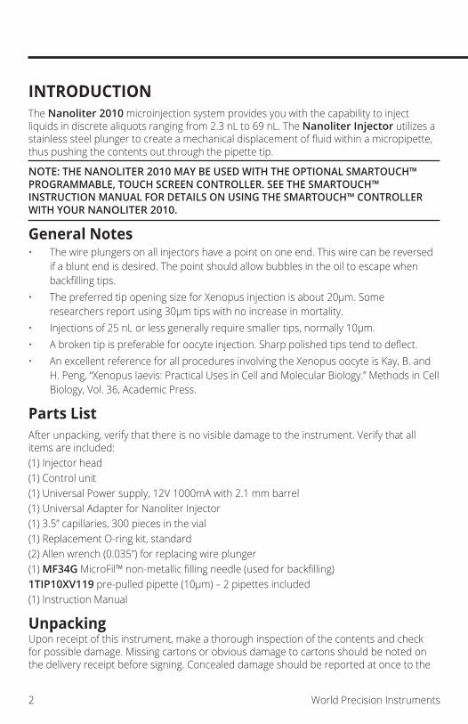
INTRODUCTIONThe Nanoliter 2010 microinjection system provides you with the capability to inject liquids in discrete aliquots ranging from 2.3 nL to 69 nL. The Nanoliter Injector utilizes a stainless steel plunger to create a mechanical displacement of fluid within a micropipette, thus pushing the contents out through the pipette tip.
NOTE: THE NANOLITER 2010 MAY BE USED WITH THE OPTIONAL SMARTOUCH™ PROGRAMMABLE, TOUCH SCREEN CONTROLLER. SEE THE SMARTOUCH™ INSTRUCTION MANUAL FOR DETAILS ON USING THE SMARTOUCH™ CONTROLLER WITH YOUR NANOLITER 2010.
General Notes• The wire plungers on all injectors have a point on one end. This wire can be reversed
if a blunt end is desired. The point should allow bubbles in the oil to escape when backfilling tips.
• The preferred tip opening size for Xenopus injection is about 20µm. Some researchers report using 30µm tips with no increase in mortality.
• Injections of 25 nL or less generally require smaller tips, normally 10µm.• A broken tip is preferable for oocyte injection. Sharp polished tips tend to deflect.• An excellent reference for all procedures involving the Xenopus oocyte is Kay, B. and
H. Peng, “Xenopus Iaevis: Practical Uses in Cell and Molecular Biology.” Methods in Cell Biology, Vol. 36, Academic Press.
Parts ListAfter unpacking, verify that there is no visible damage to the instrument. Verify that all items are included:(1) Injector head(1) Control unit(1) Universal Power supply, 12V 1000mA with 2.1 mm barrel(1) Universal Adapter for Nanoliter Injector(1) 3.5” capillaries, 300 pieces in the vial(1) Replacement O-ring kit, standard(2) Allen wrench (0.035”) for replacing wire plunger(1) MF34G MicroFil™ non-metallic filling needle (used for backfilling)1TIP10XV119 pre-pulled pipette (10µm) – 2 pipettes included(1) Instruction Manual
UnpackingUpon receipt of this instrument, make a thorough inspection of the contents and check for possible damage. Missing cartons or obvious damage to cartons should be noted on the delivery receipt before signing. Concealed damage should be reported at once to the
NANOLITER 2010
World Precision Instruments 3
carrier and an inspection requested. Please read the section entitled “Claims and Returns” on page 15 of this manual. Please contact WPI Customer Service if any parts are missing at 941.371.1003 or [email protected].
Returns: Do not return any goods to WPI without obtaining prior approval (RMA # required) and instructions from WPI’s Returns Department. Goods returned (unauthorized) by collect freight may be refused. If a return shipment is necessary, use the original container, if possible. If the original container is not available, use a suitable substitute that is rigid and of adequate size. Wrap the instrument in paper or plastic surrounded with at least 100 mm (four inches) of shock absorbing material. For further details, please read the section entitled “Claims and Returns” on page 15 of this manual.
INSTRUMENT DESCRIPTIONThe Nanoliter 2010 is ready for use as received, requiring only pulled capillary tips. It is essential that only the capillaries supplied (or exact replacements) are used for pulling micropipettes. Additional replacement parts (sold separately) that are available from WPI include:
• Straight capillaries of correct diameter (1.14 mm OD and 0.5 mm ID) in two lengths: 3.5” (WPI #504949) and 7” (WPI #504950)
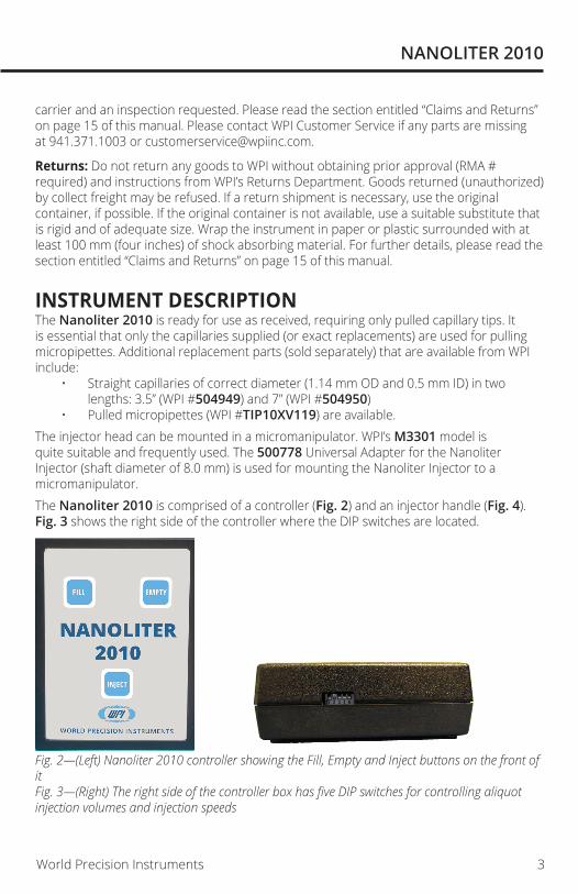
• Pulled micropipettes (WPI #TIP10XV119) are available.The injector head can be mounted in a micromanipulator. WPI’s M3301 model is quite suitable and frequently used. The 500778 Universal Adapter for the Nanoliter Injector (shaft diameter of 8.0 mm) is used for mounting the Nanoliter Injector to a micromanipulator.The Nanoliter 2010 is comprised of a controller (Fig. 2) and an injector handle (Fig. 4). Fig. 3 shows the right side of the controller where the DIP switches are located.
Fig. 2—(Left) Nanoliter 2010 controller showing the Fill, Empty and Inject buttons on the front of it Fig. 3—(Right) The right side of the controller box has five DIP switches for controlling aliquot injection volumes and injection speeds

4 World Precision Instruments
Collet
Aluminum Barrel
Plunger
Set Screws
Motor Housing
GlassO-ring with Large HolePlastic Spacer
Sealing O-Ring (small hole)
Fig. 4—Nanoliter 2010 (exploded view) shows the parts of the Nanoliter 2010 injector handle
Controller ButtonsFill–The Fill button retracts the wire plunger by one aliquot volume when the button is depressed. A beep sounds at the extreme fill position. DIP switch #5 (Fig. 3, 6) controls the rate of filling.• #5 up = 46 nL/s fill rate• #5 down = 23 nL/s fill rateEmpty–The Empty button extends the wire plunger by one aliquot volume when the button is depressed. A beep sounds at the fully extended position (approximately 24 mm from end of collet). The empty speed is approximately 92 nL/s. Fast Fill and Fast Empty–DIP switch #5 has no effect on the fast empty mode. To empty rapidly, hold down the Empty button and touch the Fill button one time. The empty speed increases to 230 nL/s. The plunger maintains the faster speed until the Empty button is released. The fill mode also has a fast speed. Hold down the Fill button and touch the Empty button one time. The fast rate varies, depending on the position of DIP switch #5 .• #5 up = 230 nL/second• #5 down = 92 nL/secondNOTE: When performing fast empty or fast fill, a beep sounds when the plunger reaches the end of travel.Inject–The aliquot volume is selected using the DIP switches on the right side of the control unit. Then, each time the Inject button is depressed, an audible beep is heard and the se-lected volume is dispensed. See “Optional Filling Technique” on page 7.
Plunger in “HOME” PositionWhen you plug in the Nanoliter 2010, it assumes it is in the “home” position. When in this position, the tip of the wire plunger should be slightly recessed from the end of the collet; the controller is at the initial position. This prevents accidental damage to the plunger when it is not in use. When the controller is at the initial position, the controller beeps when you push the Fill button. The controller has a memory of the distance from the initial position and has a stop position at about 24 mm from the initial position. The controller can make the wire plunger move up to about 24 mm, starting from the initial position. I can move shorter distances if your start from any other position between the initial and stop positions.

NANOLITER 2010
World Precision Instruments 5
Reset Initial Position for the Nanoliter 2010 ControllerDisconnect the RJ11 plug (telephone wire connector) that connects the pump and the controller, and then push the Fill button until a beep sounds. This resets the control unit to the initial position.Reset Home Position for Wire Plunger If the wire plunger is not at the home position, you can reset the home position using one of the procedures below.Using Nanoliter 2010 ControllerPush the Fill button or the Fast Reverse button to retract the plunger to the home position. If a beep sounds when you push the Fill button, but the plunger is not in the home position, then you can reset the controller manually. 1. Disconnect the RJ11 plug that connects the pump and the controller.2. Push the Empty button for 10 seconds or until a beep sounds. This gives the control
unit more range to retract the plunger.3. Insert the RJ11 plug back into the controller connection port.4. Push the Fill button to retract the plunger to the home position.5. If a beep sounds and the plunger is still not in the home position, repeat steps 1–4.6. Reset the initial position for the Nanoliter 2010 controller.
NOTE: The Nanoliter 2010 controller has a home position, the MICRO4 controller does not. When retracting the plunger with the MICRO4, stop the controller when it reaches the fully retracted point (the motor sound changes). Then reverse the MICRO4 to inject (I) it forward a small distance to prevent the motor from sticking at the full retraction.
OPERATING INSTRUCTIONSThe precise operation of the Nanoliter 2010 depends greatly on the use of tips prepared from the glass provided. Micropipettes pulled from capillaries with other dimensions may not work.
CAUTION: Never attempt to use micropipettes pulled from glass containing a filament. Damage to the wire plunger will result and injection volumes will not be accurate.
Micropipette PullingIdeally, the tip size should be pulled to 10-30µm. The capillary glass provided has a softening point of 780°C. Many researchers pull the tips smaller than required and then (using forceps) break them off at the desired size. The sharp broken edge works well to pierce the cell membrane.Once the tips are pulled, they are typically “backfilled” with oil before attachment to the injector. Silicone or mineral oil is frequently used. Backfilling is facilitated by using the flexible MicroFil™ non-metallic needle and a syringe.
NOTE: Nanoliter 2010 will not operate properly without backfilling the micropipette.

6 World Precision Instruments
Securing the Micropipette to the InjectorThe injector is supplied with the standard collet/O-ring configuration.
Standard Collet/O-ring Configuration1. Once the micropipette is backfilled, loosen the collet (Fig. 5). The pointed wire plunger
should be positioned so you can just see the tip flush with the end of the collet (slightly recessed is also acceptable). This is referred to as the “home” position.
2. Push the micropipette onto the wire plunger. As you push the tip on, feel it go through the large O-ring and seat in the white spacer. See Fig. 5 for the proper configuration of the O-rings and the white spacer. The glass end must be firmly seated in the plastic sleeve (spacer), or it could leak. It is absolutely essential that these components be properly configured.
NOTE: The O-ring is cone shaped, and the conical surface fits inside the collet as shown in the drawing (Fig. 5). The cone points toward the glass tip. This seal must have tension, or it could leak.
Sealing O-ringThe conical hole in the center points forward.This seal must have tension or it could leak.
Aluminum Barrel
Plunger
Plastic Sleeve (spacer)placed between “O” rings
with indentation toward glass
O-ring with large hole
Collet (K3)
Glass
Push the glass in, then tighten the collet.
The end of the glass must seat firmly in the gasket here, or it may leak.
Fig. 5—Standard configuration for installing the micropipette3. Once positioned, tighten the collet securely. NOTE: The white spacer has one flat side and one side with a recess machined
around the hole. This recess receives the back end of the pipette and protects the plunger sealing O-ring from damage.
NOTE: The black sealing O-ring has a small hole on one side and a larger hole on the other. The larger hole must be positioned facing the injector.
Micropipette Filling TechniquesThere are various methods for loading liquid samples into micropipettes for microinjection. A pulled micropipette has a back side and a front side.
• Back side–the non-pulled end, which has the relatively large opening that allows for rapid bulk filling
• Front side–the pulled end of the micropipette, the sharp side
The filling method of choice is usually dictated by experimental requirements and is chosen at your discretion.
NANOLITER 2010
World Precision Instruments 7
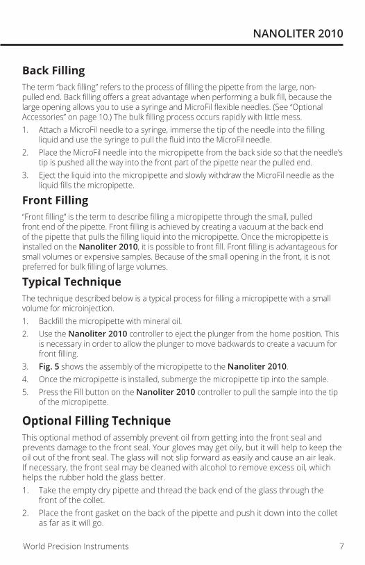
Back FillingThe term “back filling” refers to the process of filling the pipette from the large, non-pulled end. Back filling offers a great advantage when performing a bulk fill, because the large opening allows you to use a syringe and MicroFil flexible needles. (See “Optional Accessories” on page 10.) The bulk filling process occurs rapidly with little mess. 1. Attach a MicroFil needle to a syringe, immerse the tip of the needle into the filling
liquid and use the syringe to pull the fluid into the MicroFil needle.2. Place the MicroFil needle into the micropipette from the back side so that the needle’s
tip is pushed all the way into the front part of the pipette near the pulled end. 3. Eject the liquid into the micropipette and slowly withdraw the MicroFil needle as the
liquid fills the micropipette.
Front Filling“Front filling” is the term to describe filling a micropipette through the small, pulled front end of the pipette. Front filling is achieved by creating a vacuum at the back end of the pipette that pulls the filling liquid into the micropipette. Once the micropipette is installed on the Nanoliter 2010, it is possible to front fill. Front filling is advantageous for small volumes or expensive samples. Because of the small opening in the front, it is not preferred for bulk filling of large volumes.
Typical TechniqueThe technique described below is a typical process for filling a micropipette with a small volume for microinjection.1. Backfill the micropipette with mineral oil.2. Use the Nanoliter 2010 controller to eject the plunger from the home position. This
is necessary in order to allow the plunger to move backwards to create a vacuum for front filling.
3. Fig. 5 shows the assembly of the micropipette to the Nanoliter 2010.4. Once the micropipette is installed, submerge the micropipette tip into the sample. 5. Press the Fill button on the Nanoliter 2010 controller to pull the sample into the tip
of the micropipette.
Optional Filling TechniqueThis optional method of assembly prevent oil from getting into the front seal and prevents damage to the front seal. Your gloves may get oily, but it will help to keep the oil out of the front seal. The glass will not slip forward as easily and cause an air leak. If necessary, the front seal may be cleaned with alcohol to remove excess oil, which helps the rubber hold the glass better. 1. Take the empty dry pipette and thread the back end of the glass through the
front of the collet.2. Place the front gasket on the back of the pipette and push it down into the collet
as far as it will go.

8 World Precision Instruments
3. Back fill the pipette with oil within 1 mm of the top. With the plunger wire mostly retracted into the pump and the other two end seals in place on the plunger wire.
4. Assemble the collet, pipette and front seal onto the plunger wire. Some oil will spill out of the pipette as the wire is placed into the glass but it should not be allowed to get under the front seal-glass interface.
5. Wipe off the excess oil from the outside of the glass, if possible, but make sure there is no air left inside the glass when the plunger wire is placed fully into the pipette at this stage. This part may take some practice to get the oil level right to the place where there is no air left when the plunger is inserted.
6. Push and hold the glass down firmly until the middle seals seat.7. Tighten the collet to “finger tight.”
Setting the Aliquot Volume and Injection SpeedInjection aliquot volumes and injection speeds are determined by the positions of the DIP switches located on the right side of the Nanoliter 2010 control box. DIP switches #1–4 control the aliquot volume (Fig. 6). DIP switch #5 selects the fast injection rate and fill rates.
Fig. 6—The DIP switches, located on the right side of the control unit, determine the injection volumes. See Table 1.
The table below lists the DIP switch settings to use for DIP switches 1–4 to select the various aliquot volumes. (“U” = up, “D” = down). DIP switch 5 determines the fast injection and fill rates. • Up (Fast) = 46 nL/s• Down (slow) = 23 nL/s
TIP: To set the DIP switches, use a ball point pen or a jeweler’s flat head screw driver.
NOTE: DIP switch settings for the Nanoliter 2010 are completely different from the Nanoliter Injector A203.
DIP Switch Settings
Volume(nL)DIP Switch Settings
Volume(nL)DIP Switch Settings
1 2 3 4 1 2 3 42.3 U U U U 36.8 U U U D4.6 D U U U 41.4 D U U D9.2 U D U U 46.0 U D U D13.8 D D U U 50.6 D D U D18.4 U U D U 55.2 U U D D 23.0 D U D U 59.8 D U D D27.6 U D D U 64.4 U D D D32.2 D D D U 69.0 D D D D
NANOLITER 2010
World Precision Instruments 9
Injecting 1. Select the desired aliquot volume. See “Optional Filling Technique” on page 7.”2. To prime the pump, press and hold the Empty button until the plunger begins to
move.3. Then, each time the Inject button is depressed, an audible beep is heard and the
aliquot is dispensed. Pressing Inject before the first aliquot is dispensed will not produce a second injection. Wait for the beep (which indicates the injection is complete) before beginning a second injection.
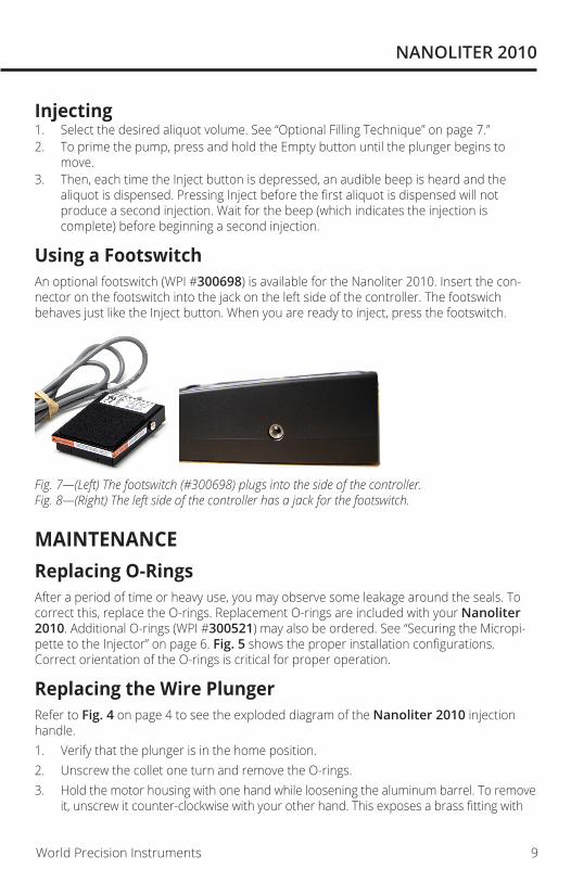
Using a FootswitchAn optional footswitch (WPI #300698) is available for the Nanoliter 2010. Insert the con-nector on the footswitch into the jack on the left side of the controller. The footswich behaves just like the Inject button. When you are ready to inject, press the footswitch.
Fig. 7—(Left) The footswitch (#300698) plugs into the side of the controller.Fig. 8—(Right) The left side of the controller has a jack for the footswitch.
MAINTENANCEReplacing O-RingsAfter a period of time or heavy use, you may observe some leakage around the seals. To correct this, replace the O-rings. Replacement O-rings are included with your Nanoliter 2010. Additional O-rings (WPI #300521) may also be ordered. See “Securing the Micropi-pette to the Injector” on page 6. Fig. 5 shows the proper installation configurations. Correct orientation of the O-rings is critical for proper operation.
Replacing the Wire PlungerRefer to Fig. 4 on page 4 to see the exploded diagram of the Nanoliter 2010 injection handle.1. Verify that the plunger is in the home position.2. Unscrew the collet one turn and remove the O-rings.3. Hold the motor housing with one hand while loosening the aluminum barrel. To remove
it, unscrew it counter-clockwise with your other hand. This exposes a brass fitting with

10 World Precision Instruments
two Allen screws on opposite sides of the brass fitting and the clear stop.
CAUTION: Do NOT disassemble the Motor Housing. Doing so may damage the plunger drive assembly.
4. Using the 0.035” hex wrench provided with the replacement plunger, loosen the two set screws.
5. Remove the plunger.6. Insert the new plunger and tighten the set screws snugly. Do NOT overtighten. Set
screws must be flush with the edge or the aluminum barrel will not seat properly. NOTE: The pointed end of the plunger is normally oriented out, be it can be inserted
either way.7. Slide the aluminum barrel over the tip of the plunger. Hold the handle so the plunger
is point straight up. Gently shake the unit until the barrel hole lines up with the plunger and slides down over it.
CAUTION: DO NOT FORCE THE ALUMINUM BARREL OVER THE PLUNGER. The plunger is easily bent.
8. Tighten the aluminum barrel in place.9. Carefully position the washers and collet on the tip of the plunger. Make sure the
washers are assembled in the proper order. Do not puncture new holes in the washers or fluid will leak through them.
10. Tighten the collet.
Cleaning RecommendationsThe injector can be cleaned by removing the collet, O-rings and spacers and wiping them with alcohol.
CAUTION: Do NOT soak the Nanoliter 2010 parts in liquid. Do NOT autoclave the Nanoliter 2010.
The control box may be cleaned by wiping it with a clean, damp cloth.
OPTIONAL ACCESSORIES504949 Replacement 3.5-in. glass capillaries (300) 504950 Replacement 7-in. glass capillaries (300) 300521 Spare Parts Kit (includes MicroFil™ MF34G, displacement plunger, five
O-ring sets, tools) 13142 Foot switch for MICRO2T controller15867 Foot switch for Micro4 controller300698 Nanoliter 2010 foot switch40239 Adapter cable for MICRO2T300033 Adapter cable, Nanoliter 2010 to Micro4500299 Replacement Plungers, 5-pack
NANOLITER 2010
World Precision Instruments 11
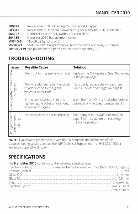
500778 Replacement Nanoliter Injector Universal Adapter503043 Replacement Universal Power Supply for Nanoliter 2010 controller504127 Nanoliter injector only (without a controller)504139 Nanoliter 2010 Replacement colletMF34G-5 MicroFil, 34g ( pkg. of 5)MICRO2T SMARTouch™ Programmable, Touch Scrren Controller, 2-ChannelTIP10XV119 Pre-pulled Micropipettes for Nanoliter Injector (10)
TROUBLESHOOTING
Issue Possible Cause Solution
Gla
ss p
ipet
te p
ushe
s off
the
pum
p tip
The front O-ring seal is worn out Replace the O-ring seals. See “Replacing O-Rings” on page 9.
The wire plunger is bent enough to add friction to the glass, which pushes it off
If it is bent, replace the wire plunger. See “DIP Switch Settings” on page 8.
O-ring seal is soaked in oil and tightening the collet is not enough to secure the glass
Wash the front O-ring in alcohol before placing it on the glass pipette shank.
Plun
ger d
oesn
’t re
trac
t com
-pl
etel
y
Home position is set incorrectly See “Plunger in “HOME” Position” on page 4 for instruction on resetting the home position.
NOTE: If you have a problem/issue with that falls outside the definitions of this troubleshooting section, contact the WPI Technical Support team at 941.371.1003 or [email protected].
SPECIFICATIONSThe Nanoliter 2010 conforms to the following specifications:Injection Volume...........................Variable-discreet aliquot volumes (See Table 1, page 8)Remote Control ............................................................................................................................YesGlass OD .............................................................................................................................. 1.14 mmGlass ID .................................................................................................................................. 0.5 mmStep ................................................................................................................................ 12.7µm/stepInjection Speed .......................................................................................................... Slow: 23 nL/s ........................................................................................................................................ Fast: 45 nL/s

12 World Precision Instruments
Fill Speed ..................................................................................................................... Slow: 23 nL/s ........................................................................................................................................ Fast: 46 nL/sEmpty Speed ......................................................................................................................... 92 nL/sSmallest Volume ......................................................................................................................2.3 nLInjections Per Filling, Max. ......................................................................................100 injectionsPower ........................................................................................... 100–240VAC, 12V DC 1000mA ...............................................................................................5.5x2.1 mm (positive center) barrelShipping Weight.............................................................................................................3 lb. (1.1kg)
APPENDIX A: FREEING STUCK PISTON WITH MICRO4 CONTROLLERSometimes the Nanoliter 2010 can get stuck in the fully withdrawn position when using the Micro4 controller. This is not a problem when using the standard controller, because it has a software limit in the withdraw direction (home position). Although there is no limit in the inject direction, this generally is not a problem, because the piston usually comes into contact with the tapered end of the micropipette and may even push the glass forward before driving further into the mechanical limit. It is easy to see when the piston is approaching the mechanical limit in the forward direction, but not so easy in the retracted position, because the piston is hidden from view once it is recessed below the hole in the collet.The Micro4 controller does not have a software limit (home position). If the head is allowed to continue running in withdraw mode after the piston is fully retracted, a bind can occur. The bind occurs as a consequence of continuous tightening of the lead screw threads into the drive nut assembly.The way to prevent the possibility of a bind is to halt the withdrawal of the piston before it reaches the mechanical limit. This can be done by visually monitoring the position of the piston during the injection process, and making sure that once it is retracted into the opening in the collet the withdrawal is stopped. It is also possible to address the issue by calculating the travel distance per unit volume and programming the Micro4 to halt withdrawal before the mechanical limit is reached. In the event that the mechanical limit in withdrawal is reached, it is possible that the unit could get stuck in this position. If this happens, it is possible to free the bind by performing some minor disassembly. To release a bind:1. Remove the collet (and internal seals) from the tip.
Fig. 9—Remove the collet by untwisting it.

NANOLITER 2010
World Precision Instruments 13
2. Remove the cylinder by turning it counter-clockwise (looking into the tip).
Fig. 10—Turn the cylinder counter-clockwise to remove it.3. Using a 0.89 mm hex wrench, loosen the two screws securing the brass clamp which
secures the piston. This releases the binding tension on the lead screw.
Fig. 11—Lossen the hex screws to release the bind.4. Re-tighten the screws on the brass clamp to secure the piston.5. Test the Nanoliter 2010 head by running the piston through its full range of travel
without driving it into the mechanical limit in withdrawal. The mechanical limit in withdrawal is reached when the brass clamp comes into tight contact with the body of the pump.
If the head is operational, re-assemble the cylinder and collet and test again.
TIP: There is a trick to putting the cylinder back on. Hold the injector head with the piston pointed upward. Gently place the cylinder on top of the piston and release it without worrying about locating the piston in the hole. While maintaining the upright position, shake the body of the injector head back and forth perpendicular to the axis of the piston. This will cause the cylinder to move around randomly on the tip of the piston until the hole in the end “auto locates” on the piston and falls into position. Then simply turn the cylinder clockwise with gentle pressure to re-tighten it. Do NOT over-tighten it!

14 World Precision Instruments
DECLARATION OF CONFORMITY

NANOLITER 2010
World Precision Instruments 15
* Electrodes, batteries and other consumable parts are warranted for 30 days only from the date on which the customer receives these items.
WARRANTYWPI (World Precision Instruments) warrants to the original purchaser that this equipment, including its components and parts, shall be free from defects in material and workmanship for a period of one year* from the date of receipt. WPI’s obligation under this warranty shall be limited to repair or replacement, at WPI’s option, of the equipment or defective components or parts upon receipt thereof f.o.b. WPI, Sarasota, Florida U.S.A. Return of a repaired instrument shall be f.o.b. Sarasota.
The above warranty is contingent upon normal usage and does not cover products which have been modified without WPI’s approval or which have been subjected to unusual physical or electrical stress or on which the original identification marks have been removed or altered. The above warranty will not apply if adjustment, repair or parts replacement is required because of accident, neglect, misuse, failure of electric power, air conditioning, humidity control, or causes other than normal and ordinary usage.
To the extent that any of its equipment is furnished by a manufacturer other than WPI, the foregoing warranty shall be applicable only to the extent of the warranty furnished by such other manufacturer. This warranty will not apply to appearance terms, such as knobs, handles, dials or the like.
WPI makes no warranty of any kind, express or implied or statutory, including without limitation any warranties of merchantability and/or fitness for a particular purpose. WPI shall not be liable for any damages, whether direct, indirect, special or consequential arising from a failure of this product to operate in the manner desired by the user. WPI shall not be liable for any damage to data or property that may be caused directly or indirectly by use of this product.
Claims and ReturnsInspect all shipments upon receipt. Missing cartons or obvious damage to cartons should be noted on the delivery receipt before signing. Concealed loss or damage should be reported at once to the carrier and an inspection requested. All claims for shortage or damage must be made within ten (10) days after receipt of shipment. Claims for lost shipments must be made within thirty (30) days of receipt of invoice or other notification of shipment. Please save damaged or pilfered cartons until claim is settled. In some instances, photographic documentation may be required. Some items are time-sensitive; WPI assumes no extended warranty or any liability for use beyond the date specified on the container
Do not return any goods to us without obtaining prior approval and instructions from our Returns Department. Goods returned (unauthorized) by collect freight may be refused. Goods accepted for restocking will be exchanged or credited to your WPI account. Goods returned which were ordered by customers in error are subject to a 25% restocking charge. Equipment which was built as a special order cannot be returned.
RepairsContact our Customer Service Department for assistance in the repair of apparatus. Do not return goods until instructions have been received. Returned items must be securely packed to prevent further damage in transit. The Customer is responsible for paying shipping expenses, including adequate insurance on all items returned for repairs. Identification of the item(s) by model number, name, as well as complete description of the difficulties experienced should be written on the repair purchase order and on a tag attached to the item.

USA175 Sarasota Center Blvd., Sarasota FL 34240-9258
Tel: 941-371-1003 • Fax: 941-377-5428 • E-mail: [email protected]
1 Hunting Gate, Hitchin, Hertfordshire SG4 0TJ Tel: 44 (0)1462 424700 • Fax: 44 (0)1462 424701 • E-mail: [email protected]
GermanySaarstraße 23, D-61169 Friedberg (Hesson), Germany
Tel: +49 (0)6031 1602171 • Fax: +49 (0)6031 1602180 • E-mail: [email protected] & Hong Kong
WPI Shanghai Trading Co., Ltd.Rm 18A, No8 Dongfang Rd., Pudong District, Shanghai, 200120 PR China
Tel: +86 21 6888 5517 • E-mail:[email protected]
Av. Conselheiro Nébias, 756 sala 2611, Santos-CEP: 11045-002, São Paulo Brazil Tel: (013) 406-29703 • E-mail: [email protected]
Internetwww.wpiinc.com • www.wpi-europe.com • www.wpiinc.net • www.wpibrasil.com.br