magnet release notes - sokkia · magnet office v5.1.1 is an update to the magnet office product...
TRANSCRIPT

Release NotesMAGNET Software System
Version 5.0 - 5.2.1May 3, 2019
© 2011-2019 Topcon Positioning Systems, Inc., All rights Reserved
The information contained in this document is confidential and is intended s olely for the use of the individual or entity to which it was sent. Youshould not copy, disclose or distribute this document without the authority of Topcon Positioning Systems, Inc.

2
© 2011-2019 Topcon Positioning Systems, Inc., All rights Reserved
MAGNET V5.X Release Notes - Introduction
Please take time to read these Release Notes. They contain information about the following:New FeaturesImprovements Bug fixes
NOTE:It is always recommended, before upgrading your field software, users backup their original job; and following any update toyour field software, users perform in-the-field checks to ensure data integrity

3
© 2011-2019 Topcon Positioning Systems, Inc., All rights Reserved
Table of Contents
MAGNET Field - V5.2.1 5 General 5MAGNET Field - V5.2 6 General 6MAGNET Office 5.1.1 9 General 9MAGNET Field - V 5.1 11 General 11 Coordinate System 15 Calculate 15 Equipment 16 Exchange 17 Resolved Issues 18MAGNET Enterprise 23 General 23MAGNET Office - V5.1 24 General - All Office Products 24 Resolved Issues - All Office Products 28 MAGNET Layout 29 MAGNET Survey 29 MAGNET Site 31 MAGNET Construction 34 MAGNET Project 35 MAGNET OFfice Tools 37 MAGNET Exchange for Autodesk 38MAGNET Field - V5.0 39 General 39 Calculate 42 Configure 43 Coordinate System 46 Equipment 47 Exchange 48 Edit 55 Job 58 Map 59 Setup 64 Survey 65 Stake 68 Reports 74 Resolved Issues 74MAGNET Office 5.0.1 78 General 78MAGNET Office - V5.0 80 General - All Office Products 80 MAGNET Site, Topo and Layout 88 MAGNET Site and Topo 90

4
© 2011-2019 Topcon Positioning Systems, Inc., All rights Reserved
MAGNET 3D Exchange 97 MAGNET Office Topo 98 MAGNET Office Site 98 MAGNET Office Resurface 106 MAGNET Office Takeoff 110 Resolved Issues - All Office Products 110MAGNET Tools - V5.0 112 General 112MAGNET Exchange for Autodesk 116 General 116

5
© 2011-2019 Topcon Positioning Systems, Inc., All rights Reserved
MAGNET Field - V5.2.1
General
The following additions/revisions have been made to MAGNET Field and MAGNET FieldLayout
Unless noted, the improvements and/or revisions listed below are included in all MAGNETField Products
Resolved Issues:
Resolved an issue when opening jobs from earlier versions of MAGNET Field. MAGNETField would show a "unable to perform recomputations" and "failed to open job!" error messages.
Resolved an issue when Exporting Raw Data in SDR33 format. If you selected 'UseFilters', the Raw Data would not export to the file, only objects would export.
Resolved an issue when importing *.DGN files that had millimeters (mm) as Units. Onimport, MAGNET Field would crash.
After upgrading MAGNET Field to V 5.2, 2012a Geoid was no longer available. This updateincludes both the 2012a & 2012b Geoid files included in the installatio n.

6
© 2011-2019 Topcon Positioning Systems, Inc., All rights Reserved
MAGNET Field - V5.2
General
The following additions/revisions have been made to MAGNET Field and MAGNET FieldLayout
Unless noted, the improvements and/or revisions listed below are included in all MAGNETField Products
Import/Export
Updated MaXML import/export support to V1.3 Improved LandXML/DXF/DWG import
New Equipment
Added support for the Topcon HiperVR with internal cell modem
Measurements
GNSSo Added support for Prism Spacer antennas for the HiperVR and Sokkia GRX3o Addressed the GPS Week Rollover
Opticalo Improved job start time when using MAGNET Field OnBoard a Topcon OS Manual
Total Stationo Added support for the Vertical Search Offset option in the Motorized Configurationo Improved the Find Station workflow in Precise Measure mode
Piping and Trenching Module
Extended the 'Trench' code to include a Radius Attribute (VPI) Switched to bisector mode when building surfaces for trenches Dramatically improved the surface generation logic Added the Horizontal Deflection text label (H Deflection) to the Measure Screen
Map
Added support for new WMS servers in Germany, Sweden and Austria Improved 3D Map navigation
7
© 2011-2019 Topcon Positioning Systems, Inc., All rights Reserved
Stakeout
Added the Topo button as an option in the Stake Map customizable toolbar
Resolved Issues
Addressed an issue when importing *.CLIP files. When importing the 3 elements of aroad (PLT, TRV, ALZ) the cross section places it at ground level, when it should bebelow. In addition, when analyzing the cross section from the edit menu, at timesMAGNET Field would crash.
Addressed an issue when creating lines from points. When creating a line between twopoints MAGNET Field would close.
Addressed an issue when importing *.dgn files into MAGNET Field. At times, the filewould not import in the correct position.
Corrected an issue when exporting a LandXML file to Leica Captivate software. Thechainages reported when opening the file in Leica Captivate were not correct.
Corrected an issue when configuring MAGNET Field in French. The VA and SD wo uldappear twice in the Backsight record, and the first set would not contain any values.
Updated support for WMS mapping servers and now support CRS:84 and EPSG:4258.
Corrected an issue with the 2 Distance Offset calculation. MAGNET Field would return aresult even if no solution was possible.
Addressed an issue when incrementing point numbers starting with 0xx. If you exit theSurvey/Topo screen, then start Suvey/Topo again, the starting point number would notbe the correct incremented value.
Addressed an issue in GNSS survey if ’prompt for antenna height’ is enabled. If theheight is more than 6.554m, the value was not allowed and an error message wasshown.
Corrected an issue when exporting to STAR*NET.DAT format, a 'Not supported format'error message was shown.
When MAGNET Field was configured for Network RTK, the routine GGA position wouldnot provide a fixed solution if the ‘Rover Position for NTRIP server’ checkbox wasselected.
Corrected an issue when using a WMS mapping server from the Swedish Lantmateriet.

8
© 2011-2019 Topcon Positioning Systems, Inc., All rights Reserved
Corrected an issue when connecting to a Sonar Hydrolite depth sounder. The depthwas reported as N/A.
Corrected an issue when exporting lines to DXF/DWG from MAGNET Field running on aFC500 or MAGNET Field OnBoard. The export would fail.
Addressed an issue when using online help with certain languages. (NL, DE, ES, FR).
Addressed an issue when MAGNET Field is configured for a Hybrid survey. The heightadapter was not added to the height calculation.
Addressed an issue with Import/Export of AutoCAD Drawings (*.dwg/*,dxf) whenrunning MAGNET Field on a Tesla. The files would not import or export.
Corrected an issue in Stake Road. When in Stake> Road, the prism constant displayedan incorrect value of 99.9.
Corrected an issue when staking roads with all transition points selected and the stationinterval set to 50.00. The 50.00 increment was not used.
Addressed an issue in the *.FBK output format. The file would not show the rawangular observation data.
Addressed an issue when exporting raw data to the Topcon Custom TS (*.txt) format. the Refraction PPM value was always 0.000

9
© 2011-2019 Topcon Positioning Systems, Inc., All rights Reserved
MAGNET Office 5.1.1
General
MAGNET Office V5.1.1 Release Notes
Magnet Office v5.1.1 is an update to the MAGNET Office product suite and addresses issueswith the Import and Export of *.dwg files. Additional reported high priority items have alsobeen addressed.
Note: Fixes listed are added to product configurations that include the referencedfunctionality.
Corrected a crashing issue when using the Insert Perpendicular Line optio n.
Corrected an issue with Extend/Trim option not working when the intersecting point isnot along the selected entity reference for extending or trimming to.
Fixed an issue with Export to Leica Roadrunner files causing a program crash.
Corrected an issue with Data Cleanup not working with a singularly selected item.
Modify> Extend/Trim: Fixed an issue with extending entities when the intersectingentity does not cross the extend/trim entity.
Corrected an issue with Modify Line, Insert Point, not working on computers runningWindows 7.
Export to dwg:
o Updated the AutoCAD tab in the Export dialog.
o Added a new flag to the export dialog to export annotation as text. If the flag isON, the annotation of the data exported is exported as text.
o Reinstated option to export as 2D. A new option, “Export Point Heights” wasadded to optionally export point heights.
o Fixed an issue with exporting of contours from the Survey View. Contours areexported as polylines if they are set to be displayed in the project.
o Fixed an issue with fonts not being retained when exporting to *.dwg.
o Corrected an issue with the image transparency setting in Magnet Office notbeing retained in resulting *.dwg file.

10
© 2011-2019 Topcon Positioning Systems, Inc., All rights Reserved
o Reinstated the option to export DTM as a mesh.
o Corrected an issue with Text font not retained with exporting text to *.dwg.
o Fixed issue with contours not being exported to *.dwg.
o Fixed issue with point marks/symbols when set to bylayer not being exported to*.dwg.
Import dwg:
o Reinstated the unit check and override options when importing a dwg file.
o The Explode Blocks during import setting has been set to Off as the defaultsetting.
o Fixed an issue with the Create Points on Linework option. When toggled off,points were still being created.
o Reinstated elevation flag Off for points and polylines with elevation set to 0.
o Reinstated support for retaining Multiline text font and position as defined inAcad.

11
© 2011-2019 Topcon Positioning Systems, Inc., All rights Reserved
MAGNET Field - V 5.1
General
The following additions/revisions have been made to MAGNET Field and MAGNET FieldLayout
Unless noted, the improvements and/or revisions listed below are included in all MAGNETField Products
New Features/Improvements:
Added a New Piping and Trenching module to MAGNET FieldThe new module was built to facilitate in-field oil and gas pipeline design andconstruction. This new module greatly improves the COGO, mapping, and exchangefunctions in MAGNET Field to simplify use for this type of work and deliver analignment, profile and, cross-section set for 3DMC so that the pipe trench can beexcavated.
o The Piping and Trenching Module includes the following features:
Added Reference CL to Topo so you can get station/offset distances asrelated to an alignment in Survey > Topo.
Added the ability to create a Surface from a Road. Allow the user to selecta road on the map and in the Context menu, added ‘Create Surface’.
Added Profile view as an option for Map View. The Profile view displays thelast 5 stored points, current rod location, current depth valude and a dottedline is shown from the last stored point to the current rod location
Automatically create a trench from the surveyed points based on the Codeand Attributes assigned to the Trench. The attributes include Width, Depthand Slope of the trench. Trench is included as a new Code with the Pipingand Trenching module.
Added the ability to construct a Trench based on a string defined by TrenchCodes with Attributes (width and slopes) with a profile and cross sectionset.
In Calculate > Offsets added the option to calculate the vertical intersection

12
© 2011-2019 Topcon Positioning Systems, Inc., All rights Reserved
point (PI).
Added the option to show the grade in DMS when the Piping and TrenchingModule is activated.
Added a new 3D corner angle routine that shows:
Slope from Start to Middle
Grade (Slope)
Grade (Degrees)
Slope to Middle to End
Grade (Slope)
Grade (Degrees)
VPI Deflection Angle (Over Bend or Sag)
General Features/Improvements:
Added the Cross Section view to Surfaces
Added the Volume report in Stake > Surface (Road). Check the Create Surface optioncut/fill, enter the name and when finished staking the Volume report is now available
Updated Hybrid search so if there is a large difference between the height of the GNSSreceiver and the prism, the Total Station will now turn to the X and Y position of theGNSS receiver but use the Height of the Prism. The Speed when Locating and Trackingthe prism has greatly improved.
Added support for Civil3d Point properties on import including Point Number, Fulldescription and, Codes
o In V5.1 MAGNET Field now Imports Point Numbers as Point Names, FullDescription as Point Note and, Code/Attributes as Code/Attributes
Added the option ‘Fillet 0’ to the Join Linework command
Updated the display options for ‘Display Slope As' in Configure > Display to include:
o 1: Run (x)

13
© 2011-2019 Topcon Positioning Systems, Inc., All rights Reserved
o Run (X) : 1
Which represents Rise:Run and Run:Rise.
Added an option in Edit > Layers to Select and delete all layers when there is data in thelayers.
Added support for Lat/Long format in geoTIFF. geoTIFF handles geo information (OriginPoint and Scale) in Lat Long Format. Users can add images in geoTIFF format and ‘Degrees’ in units in the image property dialogs.
Updated the scale bar in the 3D view to match the 2D view scale bar.
In the Survey View, updated the Enterprise connection state to show the state(Connected/Disconnected).
Added the option to allow users to adjust background drawings by point. Options nowinclude: Transform by Points, Transform by Line.
in Edit > Raw Data, added a column to show Galileo Satellites.
Added support to create a Surface from a Road in the Main Map. The option is available inthe context menu.
Added support for CAD meshes when importing as a background drawing.
Added the option ‘Yes to All’ when deleting multiple surfaces and points.
Updated selection in the 3D view so when lines are selected, the lines are highlighted onthe 3D map.
Added support for Hybrid Surveys in X-Section Surveys.
Moved ‘Mission Planning’ to the GNSS Setup page.
Allow multiple users to use a single license/Activation. If there are multiple user acco untson a Windows device, MAGNET Field will now allow all users of the device to use theactivation.
Updated ‘Stake Real-Time Road’ with Ref Surfaces so if the CL Offsets is set to the default(0), the user can now bypass entering CL offset values and either extend cut/fill slopesfrom the edge of the reference surface or extend the outer triangles of the referencesurface.
Added Slope Distance (3D Length) to Inverse Calculations
o Pt to Line

14
© 2011-2019 Topcon Positioning Systems, Inc., All rights Reserved
o Pt to List
o Pt to Curve
o Pt to Road
o Pt to Linework
Updated the default settings when MAGNET Field is configured for Japanese language tomeet the local Public Survey work in Japan.
Added an option to show only the Quick button, Precise button or both.
Updated BS setup so the reverse face raw data is now recorded in the data file (*.mjf).
Added the 2 button (Precise/Quick) feature to Set Collection.
in Set Collection, Observations are now stored after each direction.
In Set collection, added the ability to interrupt the set and start Topo>Sideshot, thenreturn to Set Collection after the Sideshot(s).
In all measurement windows, after selecting all transition points, the transition pointnames are show on the map.
In Edit > Raw Data, the station names are now show with the selected point.
Added an option 'Measure Nearest Point' for both GNSS and TS observations; and allowa range (value) to be entered. If measuring a point within that range, the 'Objects nearselected point' dialog appears and points within the specified range are listed. Measuring a point beyond the specified range will not display the dialo g.
Updated the export to SIMA format to include the Road or Hz Alignment name.
Updated exporting to DLF format to export to a single folder.
Added the option to increment by ‘Day of the Year’ in an RTK session.
Added support for the Vertical search offset in Set Collection.
Restored the option to save the L1 PC of Network RTK/DGPS base station as a manualpoint.
Added 'Reference CL' as an option for all survey routines. Custom text labels on themap also have the display option to support showing reference position.
Added a Profile view for all survey routines.

15
© 2011-2019 Topcon Positioning Systems, Inc., All rights Reserved
The Labels for Geocentric Coordinate Systems are now: Xc Yc Zc
Coordinate System
New Features/Improvements:
Added support for importing and exporting custom projections
Updated the Table of Corrections for the Czech transformations for the globaltransformation from ETRF to the Czech coordinate system Krovak.
Added the option to choose the Datum transformation method in MAGNET Field:
o From WGS84 to Local Datum o Local Datum to WGS84
Added MapGEO 2015 geoid model for Brazil
New Geoid model for Belgium (hBG18)
Calculate
Transform:o Drawing Transform: added the option in Calculate > Transform to transform a
background vector image by: Matching Point/ Matching Line/Plotting Scale
o Image Transform: added the option in Calculate > Transform a background imageby: Matching Point/ Matching Line/Plotting Scale
Added Slope Distance (3D length) to Inverse results
Added the ability in COGO to calculate a Vertical Intersection (slope) from two lines. Thelines do not have to intersect horizontally.
o From the map, select the lines you want to calculate the vertical intersection.
o Right click and select, Slope Intersection.
o Magnet Field will extract the grade from each line and determine the VPI based onthe end points.

16
© 2011-2019 Topcon Positioning Systems, Inc., All rights Reserved
o Store the point at the mean location of the two lines closes end points.
Added the option to calculate a 3D Corner Angle that shows the following additional data:
o Slope from Start to Middle
o Grade(Slope)
o Grade(Degrees)
o Slope from Middle to End
o Grade(Slope)
o Grade(Degrees)
o VPI Deflection Angle (Over Bend or Sag)
Added the ability to Translate and Rotate Optical measured points.
Equipment
New Features/Improvements:
GNSS Enhancements
Added support for the HiperVR GNSS Receiver.
Updated the Position for GGA dialog to add the ‘Rover Pos for NTRIP Server’ checkbox. Added the option to Use Fixed GGA when connecting to VRS so when a VRS mountpoint
is detected, the actual rover position will be sent to the NTRIP server to generate theVRS coordinates.
Added a WiFi Configuration feature to MAGNET Field. Under Receiver Management, theuser can now control the WiFi settings This is available for receivers that have WiFisupport.
Updated the SRL-35 radio configuration support so once an initial connection has beenmade, the user is no longer queried for the communication setting to be accepted. TheRadio Configuration is now saved in the background.
Updated the Radio Link icon to include the following visual indicators:o 98-100%, Green, 4 bars of 4

17
© 2011-2019 Topcon Positioning Systems, Inc., All rights Reserved
o 80-97%, Green, 3 barso 50-79%, yellow, 2 barso 1-49%, orange, 1 baro 0% red dot, no bars
Added a warning message when starting the base with antenna heights that exceedRTK Protocol limits of 6.3 meters.
Added support for 8FSK and 16FSK protocols for the R4T-BT radio.
Renamed ‘Clear NVRAM’ to ‘Factory Reset’
All supported Satellite Systems can now be used in a Relay Session.
Added Mission Planning to the Main Menu.
Added the option to display the IMEI and MEID Number in Receiver Information.
Added the option in Setup > Receiver management > Info to ‘Save to File’ thereceiver info.
Receiver recovery view is now in Receiver Management and includes auto and manualrecovery.
When configured for mmGPS+, the Fixed mmGPS+ solution type is now set by default.
Added an option to enable NMEA GNGMP message output on a Field Controller SerialPort. The option allows you to select any Grid or Datum + GG parameters for output.
Added support for Image capture using the camera on the T-18 Controller.
Added support for the internal GNSS on a Panasonic Toughpad.
Added support for the SRL-35 radio as a Repeater.
Added support for the Alinco 2 radio.
Optical Enhancements
Added Guide Light Icon in the toolbarr for MAGNET Field OnBoard on the OS/FX
Exchange

18
© 2011-2019 Topcon Positioning Systems, Inc., All rights Reserved
New Features/Improvements:
PDF:o Added the ability to import a pdf as a background image in MAGNET Field.
o MAGNET users can now import and attach a pdf as a background image to theirjobs in MAGNET Field Map.
Added the option to set the insertion point and Scale.
The scale can be defined by picking either points or lines on the padand then in the MAGNET Field job. Users can select two points on thepdf (image) and two points in the job. MAGNET Field will transform(Rotate/Scale) the image based on the selected points in the Job. Therotated/scaled pdf will then be stored as a background image.
Option 2 when inserting the pdf to a job is to pick two points on the image(or a line) and then enter the distance between the points (line length) aswell as the rotation angle. MAGNET field will rotate/scale the pdf based onthe distance and rotation angle entered.
Added the option to write the Project Name in a TP3 file as the File Name.
Added support when exporting raw date in the RW5 format for Direct/Reverse readings.
Added support to create a worldfile for jpg/tiff format.
MaXML Improvementso 1.2 Import/Export Supporto Custom Projection Import from MaXML
Import Civil 3D point properties from DXF/DWG including Point Number, Full Descriptionand Codes
Improved Surface(s) import from CAD formats. Meshes are now supported
Resolved Issues

19
© 2011-2019 Topcon Positioning Systems, Inc., All rights Reserved
Resolved Issues:
Coordinate Systems:
o in V5.0 on a WM devices, the Czech Table Projection would not show in the list ofCoordinate Systems.
o Updated the Geoid list so Geoid 12B would install. In the previous release, Geoid12B was not available.
o In MAGNET-Field (version 4.3.3) when using RTCM3-Online-Transformation datafrom the reference network SAPOS to get Gauss-Krüger-coordinates andDHHN2016-heights. At times, the coordinate values would differ by up to 4cm (X,Y)and 8cm (Ht).
Stake > Road:
o At times, the prism constant values would not display correctly. Selecting the PrismIcon and reselecting the correct prism would then refresh the display.
o When staking a road with all transition points selected and the station interval set. The entered station interval would not be used when advancing the station.
Upgrading Jobs:
o When upgrading a job (*.mjf) from 4.3.x to 5.0. At times, the job files would notopen.
o When updating a job from MAGNET Field 3.3.1 to MAGNET field 5.0. The surface inthe job file was not imported.
Raw Data file:
o Addressed and issue when storing raw data. Points stored show the timestamp inUTC time not the local time off the controller or device.
Export:
o Raw Data export to RW5 format. When exporting data, an ‘invalid display’ errormessage would show.
o When exporting in the Topcon Text custom format. If you first export a dwg/dxf, thecoordinates decimal places for the points of the Custom text file would not export.
o When exporting Raw Data to the GTS-7 format. If points were measured with two

20
© 2011-2019 Topcon Positioning Systems, Inc., All rights Reserved
faces, when the raw data was exported, the points would only have one (1)measurement.
o When exporting Points by Codes (filter). All points were exported and not just Pointswith Codes.
o Addressed an issue when exporting raw data to the KOF format. The base stationrecord was not stored correctly.
o When exporting a job with a Localization to a *.tp3. The localization would not bewritten to the file.
o FBK format raw data output: The export file would not show the raw angularobservation data of direct and reverse for TS measurements . Only the averagedangular values of the horizontal and zenith angle were exported.
o When exporting LandXML files, if the job data was collected using Hybrid, the formatof the file was incorrect.
o Addressed an issue when exporting to the GTS-7 format. The file was not storingoffset points correctly.
o When exporting TS raw data to Topcon Custom TS (*.txt) the Refraction PPM cannow be included with the raw data export.
Import:
o When importing a LandXML file that contains a road(s), at times the road would notimport and resulted in an undefined error on import.
o When importing Microstation DGN files, MAGNET Field would default to metric if theuser did not specify the dgn file import units.
o When importing points using the Topcon Text Custom format. If the points werelocal points with ground coordinates and the projection was set to ‘none’, the filewould not import.
o Importing background images. When importing TIFF files, if the background imagewas white, the image background would switch to black so linework and points werenot visible.
Quick Codes:
o When editing the line code, the entered number was at times not stored correctly.

21
© 2011-2019 Topcon Positioning Systems, Inc., All rights Reserved
o When using portrait mode on a Field Controller, the quick code button in the TopoMap view the button text has string values that are cut off. The buttons will nowscale to allow the full text of the Quick Code be displayed when in portrait mode.
Total Stations:
o In MAGNET Field v5.0; when changing to Sheet, MAGNET Field did not send the 0.0Constant to the Total Station.
o In Remote Benchmark, at times the setup would not update with the elevation fromthe Benchmark.
o In Remote Benchmark with multiple setups, the first Occupation point name wouldshow for the second, third, etc. setups.
o When the instrument configuration is set to Direct/Reverse. If the Measure reversedistance box is checked after direct measurement when turning to Face 2observation measure/store button disabled and will not take a measurement.
GNSS:
o GLONASS: when using GLONASS in the solution, and the RTCM 3 MSM format, attimes GLONASS was not used in the solution.
o DGPS: Addressed an issue when connecting to the internal GNSS with a DGPSconfiguration on a S-10 Controller.
o Addressed an issue when connecting to a Trimble network. MAGNET Field V 5.0 wasnot able to retrieve the source table from the Trimble Caster network in Kuwait(Trimble Ntrip Caster 3.1 created by Trimble Pivot Platform).
o Correct Base: Point averaging was not allowed when using Correct Base, and only asingle epoch could be used.
o When working in a reference network, using MAGNET Field on a WM Controller, andconnecting to a mount point which transmits an online datum, the new datum-namewould not be displayed.
o Addressed an issue when connecting to a MR-1 GNSS receiver. When connecting,you would get a ‘incorrect antenna type’ error message and you could not start abase.
General
o Addressed an issue when connecting to a WMS services located in Italy. Except in

22
© 2011-2019 Topcon Positioning Systems, Inc., All rights Reserved
the case of EPSG projections, WMS server connections are now loading.
o Addressed an issue when loading custom menu configurations in V5.0. The menuwould load, but restarting MAGNET Field would return the menu to the default(Factory) MAGNET Field configuration.
o Addressed an issue when changing the virtual ports in MAGNET Field. Whenconnected to a HiperHR, an 'Incompatable Receiver, Wrong Radio or, Virtual Portsetting error message would display.
o Addressed an issue when enabling Bing/OSM maps on a WM/CE Field Controller. Attimes, the device would hang and not load the maps.
o Addressed an issue when connected to a Topcon GPT-805A Total Station. Whenconnected using a RC2, the measurement screen would not show anymeasurements.
o Survey: When measuring points with GNSS and entering codes from the keyboard. The cursor by default is always in one place, so if you press ABC in code beforemoving the cursor to the Code Field, you would only get C.
o Addressed a performance issue when running MAGNET Field on a Windows Mobilecontroller. The background would no longer refresh and commands were slow torespond.
o Addressed an issue when connected to a Topcon GT Total Station. The arrow keyswould not respond when turning the total station
o Addressed an issue with Special characters on the MAGNET Keyboard. %, @, \, ( ),greyed out and not available for use.
o Addressed an issue when using copy/paste or select all on an FC-5000 FieldController. The copy/paste/select all option was not available when pressing downon the screen.

23
© 2011-2019 Topcon Positioning Systems, Inc., All rights Reserved
MAGNET Enterprise
General
Added support for concurrent logins from MAGNET Field, Enterprise and Office. Usersmay now log in from separate applications using the same Enterprise Login credentials.

24
© 2011-2019 Topcon Positioning Systems, Inc., All rights Reserved
MAGNET Office - V5.1
General - All Office Products
MAGNET Office V5.1 Release Notes
Magnet Office v5.1 is a general release of the various modules that are available in theMagnet Office product suite. Included in this release is a reconfiguration of the existingproducts and modules. The reconfiguration has been done to simplify the product offeringswithout a reduction of functionality. All the new product configurations have increased andimproved the functionality of the old products.
The following table shows the New MAGNET Office Product configuration(s) compared to theexisting MAGNET Office products.
Notes:
Magnet 3D Exchange is not included in the reconfiguration of Magnet Office andremains as a standalone product. New Features and Improvements listed below areincluded in Magnet 3D Exchange. Fixed Issues listed below are included where

25
© 2011-2019 Topcon Positioning Systems, Inc., All rights Reserved
applicable. Some fixed issues listed may apply to a function not included in Magnet 3DExchange.
Specific functionality additions, improvements, revisions and corrections are listedbelow by Magnet Office product. New product names are used, please refer to theabove matrix to determine the updates that apply to the new configurations.
General
The general improvements listed below are included in all Magnet Office products unlessotherwise noted.
New Features and Improvements
License Check In/Out – Magnet Office products included in the reconfiguration andnew products listed above include the ability to check in/out a license. Thisfunctionality allows the user access to MAGNET Office from any computer it has beeninstalled.
A typical example is the user has MAGNET Office installed on both a work and homecomputer. From either computer, the user can check the license out to work withMAGNET Office, and then check the license back in when they are done working.
The requirements to use Check In/Out are:
o Requires a connection to the internet at least once during a 30 day period.
o Requires manual check in/out of license
o Requires valid product serial number when checking in/out
o Requires that your subscription is valid (service plan/maintenance) to enablecheck in/out.
Activation Workflow:
o Initial activation of the product automatically executes a “check out” of thelicenses.
Once activated if the license is not required to be used from othercomputers, there is no need to check the license in.
o Initial activation and Check Out workflow:
Launch product
Activation Required notice displayed
Select activation type. (this workflow details online type)

26
© 2011-2019 Topcon Positioning Systems, Inc., All rights Reserved
Enter Magnet Enterprise credentials to login
Enter serial number and select device ID
Product Activation dialog will display including the Check Out and Check Inoptions.
Initial activation automatically checks out the license, selecting Check Outat this time in not required.
o Check In workflow:
From the Help Ribbon select the Licenses icon
Enter Magnet Enterprise credentials to login
On Product Activation dialog select Check In
Confirm deactivation message
Confirm product shut down message

27
© 2011-2019 Topcon Positioning Systems, Inc., All rights Reserved
Note: The prompt to save unsaved data will display before shutdown.
o Network versions of Magnet Office do not use the Cloud Check In/Outfunctionality. Server based check in/out only is provided for networkinstallations.
o Magnet 3D Exchange does not include Check In/Out functionality.
o Offline Activations and activations to a USB Key do not support check in/outfunctionality. If a license is activated via the offline method or to a USB Keycheck in/out options on the license dialog will be unavailable. Licenses activatedusing these two methods can be disabled by contacting [email protected] andthen reactivated using the online method to enable check in/out functionality.
Import - various supported file types now provide a summary of data included in thefile with the ability to select the data, layers and entities, when applicable, duringimport. Current file types supported by this option are as follows:
o MAGNET Field Job (*.mjf)o MAGNET XML (*.MXL)o MAGNET XML package (*.MXLZIP)o Bentley Infrastructure Model (icm.dgn)o Autodesk dwg/dxfo LandXMLo Inframodelo 12d ASCIIo CPIXMLo SSSo CLIPo ISPOLo SBGo SBG Pxyo SBG Geoo TDS
New LandXML import to list and allow selection of data to import.
o Supports multiple roads and provides options to define cross section spacing,design surfaces and to create dtm from cross section data on import.
Cloud Connections - added ability to create new folders in a connected project withinMagnet Enterprise Data Manager.
Elevation Prompt dialog - added the breakline toggle when creating linework.
Magnet MaXML Import/Export - updated import/export for Magnet XML (*.mxl) toinclude attributes.

28
© 2011-2019 Topcon Positioning Systems, Inc., All rights Reserved
Languages – Added Dutch and Spanish translations.
Import/Export
o Added import/export support for Leica Hexml v1.7 files
o Added export to 12d text file (*.12da)
o Export to TP3 – revised to retain specified file name during export. Previo uslythe Magnet Office project name was being used by default.
Resolved Issues - All Office Products
Fixed Issues
3D Toggle and New Tab – fixed issue with selection of entities. During the selectionof multiple entities using a crossing window or window selection, the first point in theselection was not included. Fixed issue with the individual selectio n of entitiesinconsistent selection behavior.
Import Autocad dwg – corrected issue with dwg files containing surfaces defined as3d faces. When imported the 3d faces were being converted to polygons resulting in nosurfaces imported.
Export to Autocad dwg – Background images attached to a project are now includedin the exported dwg file.
Export to TP3 –corrected issue when exporting “ active/selected layers” resulting in allproject layers being exported.
Drag & Drop to Open – fixed issue with drag and drop to open a *.mjo file. MJO filescan now be opened by drag and drop method when other projects are open.
Export to LandXML – corrected issue when using the “Selection” option in the Exportdialog. The Selection option was resulting in all project data being exported.

29
© 2011-2019 Topcon Positioning Systems, Inc., All rights Reserved
Custom Colors – fixed issue will custom color definition rgb and hsi fields notaccepting three-character input.
Raw Data Editor – updated the Raw Data Editor to display point information in blackwhen the background color set to white. (Not included in Magnet 3D Exchange)
Import Magnet Field job (*.mjf) – corrected issue with “R” rectangle command codenot working when importing mjf files. Note: during import if the “Import Linework”option is on, the rectangle will be created using a string. If the “Import Linework”option is off, the rectangle will be created using line segments.
MAGNET Layout
New Functionality and Improvements
Insert Point Offset Text
o Added the option to include or suppress the arrow when labeling the offsetdistance.
o Added a “Label Only” option to suppress the dimension line and only add theoffset text label.
o Added the ability to label multiple point offsets simultaneously. Note: selection o fthe multiple points is required before running the command.
Fixed Issues
WMS (Web Map Service) – fixed issue with some WMS supporting CRS:84 notdisplaying images. Added a new option in “Select Map Service” dialog to support“Inverse Axis Order”. If the selected WMS supports Coordinate systems with inverseaxis order (CRS:*). When the “Inverse Axis Order” is checked, the map request will besent with CRS:84 coordinate system.
MAGNET Survey

30
© 2011-2019 Topcon Positioning Systems, Inc., All rights Reserved
New Functionality and Improvements
ePlan Functionality/Support (Australia)
o Added Rounding setting to bearings when exporting to ePlan xml.
o Added support for the creation of the multipart header parcel in ePlan
o Updated ePlan support to reflect listed recent changes.
The enumeration list for RedHorizontal@horizontalFix has been updated toremove and replace GPS with Policy 3. (NSW)
ePlan 3.31.3 determination of Class and Order has been updated by addingan enumeration of NA to enums for RedVerticalObservation andRedHorizontalPosition@Order. (NSW)
Create Enclosing Boundary – revised to included option to use linework whencreating a “tight” enclosing boundary.
Delete by Boundary – the default settings for this command have been updated to set“Outside” as the area to delete and “Window” as the selection option.
Raster to Vector – added new functionality to import a pdf file and extract vectorsafter import.
o Added to the Insert ribbon, Raster/Vector ribbon group.
o Includes Recalibrate option which allows for the realignment of the pdf,transparency settings, and display toggle.
o Includes Trace option for tracing of specific raster data. Includes auto traceoption with dashed line recognition.
o Includes Extract Vector options. Extraction options include by window, crossingwindow selection or all vectors.
Note: the Raster to Vector functionality is located in the Model ribbon in MagnetSite, Construction and Project.
Fixed Issues
Roads View (Cross-Section and Profile) plotting
o Corrected issue when plotting multiple sheets, not all sheets were plotted.
o Corrected issue with sheet numbers for multiple page plotting listing page 1 of xon all sheets. Please note that, for all the existing drawings, user must clickView->Regen to correct the sheet numbers in the drawing.

31
© 2011-2019 Topcon Positioning Systems, Inc., All rights Reserved
Inverse function – added the “Clear” option in the Inverse UI to clear data. TheInverse UI retains the inverse data when closed until cleared. Note that the Inverse UIis modeless; it can be docked, floating or hidden and remain open at all times.
Horizontal Alignments (changing layers) – when selecting a horizontal alignmentand linked points in order to change the layer by selecting a layer from the layerdropdown list, only the linked points were being placed on the selected layer. Corrected workflow to also place alignment on specified layer.
Import DXF – fixed the issue with individual surfaces being combined into one surfacewhen importing dxf file.
Road View Plotting – fixed issue when plotting cross-sections or profiles to pdf.Printing to pdf at 100% scaling was not plotting all data or all sheets.
Lot Annotation – fixed issue with the Lot Name prefix label not allowing a spacebetween the prefix and lot name. When defining the prefix if a space is added after theprefix it will now be used in the lot name label.
Create Entity (Right Mouse Button, Add Tangent Arc) – Made changes to thebehavior of Create Entity -> RMB -> Add – Arc Tangent option. Note that Add ArcTangent is only available from the RMB after at least one segment of the entity iscreated. Workflow is as follows:
o Create one segment of the entity or one line in the “Create Entity” routine
o Click RMB> Add – Arc Tangent option
o A new prompt for radius “Define Radius” is displayed. User may enter the radiusin UI or select a point\location in the view to define\calculate the radius.
o After radius is defined, a field for Angle, chord or length is displayed in the UI.User may enter the values in the respective fields or select a location in the viewto automatically define\calculate the values.
Note: Create entity allows for the continuous entry of straight line segments andarcs by using direction or coordinate creation methods.
Drawing Editor – Fixed issue with print spooling from the Drawing Editor. Printspooling was delayed when a background image was present but not displayed.
MAGNET Site

32
© 2011-2019 Topcon Positioning Systems, Inc., All rights Reserved
New Features and Improvements:
Corridor Subgrades:
o Improved to include subgrade tie slope option. Allows ability to tie a subgrade tothe design surface or subgrade by user defined slope. Slopes can be defined byslope percent, ratio or degree of slope.
Edit Strings - updated to include two new options for adding points to a selectedstring.
o Distance along string
o Reference alignment station
Corridor functionality:
o Corridor Width and Slope Zones
Updated to include a new option to copy slopes/widths from one zone toanother.
Updated to include option to set zone width and/or slope to specific value
Both options are accessed by selecting “Set” in the slope zone or widthdialog.
o Corridor Strings
Added option to create additional points on corridor strings at a userdefined spacing on straights and curves.
Added option to create points on corridor strings at designatedstations/chainages.
Both options work with strings created by the corridor design orreference strings.
Corridor Cross Section Viewer
Added a new cross section viewer in the corridor ribbon. This option can be used toview and calculate volumes from cross section data using corridor data or byselecting a horizontal alignment and individual surfaces.
When selecting a corridor, the surfaces and surface types will be preloaded based onthe corridor design data. When selecting an alignment, the cross section set mustfirst be given a name, then the individual surfaces selected and their types defined.
Cross view and control panel options included are defined as follows:
o Cross Section View

33
© 2011-2019 Topcon Positioning Systems, Inc., All rights Reserved
Volume for cut, fill and subgrades are displayed for the cross-sectioninterval defined by selecting the setting button in the contro l panel. Volume data is only displayed for sections matching the interval spacing.For example an interval of 20 will display volume for stations 0, 20,40,60etc. Note that when using the slider to browse stations, the volume datais not shown in the graphic view.
Settings - use the settings button to control the display of section dataand the definition of cut/fill color shading.
o Control Panel
Name – name of cross-section set. Note that when using individualsurfaces and a specified horizontal alignment, this field must becompleted prior to selecting the horizontal alignment or surfaces.
New – clears the section data fields and allows for creation of a newcross-section set.
Delete – deletes a cross-section set. Note that when cross-section setsare created they are stored with the project and can be loaded at anytime.
Corridor – select the corridor design to display cross-section data from.To select a corridor first check on the corridor check box.
Alignment – select the horizontal alignment to use with thecross-section set.
Settings Button – specify the cross-section interval. Using theforward/back buttons at the bottom of the control panel will increase anddecrease stationing along the specified alignment.
Surface Button – use this option to select the surfaces, surface typeand materials. Material definition is optional but is provided for takeo ffcalculations if required. The order of the surfaces does not need to be defined, the program willdetermine where each surface is positioned on the cross-section. Eachsurface must have its type defined.
Calculate Volumes – with this option toggled on, total volumes, basedon cross-section average end method will be displayed in the controlpanel.
Report – this option will create a volume report.
Note: Material definitions – Are not included in Magnet Site. Requires Magnet

34
© 2011-2019 Topcon Positioning Systems, Inc., All rights Reserved
Construction or Project.
Fixed Issues
Corridor Templates – Corrected issue with corridor design resulting in program crashwhen applying multiple side templates to the right and left side o f the centerline.
MAGNET Construction
New Features and Improvements:
Resurface View – Profile Lock - Improved the profile lock option in dialogs where theoption is available. By default, the Profile Lock Option will be off when the dialo g isopened. If the option is turned on the setting will be retained for the specific ro utinewithin the project. The profile lock settings per command are retained at a projectlevel. New projects created will use the default setting for this option until changed bythe user.
Corridor Subgrades:
o Improved to include a subgrade tie slope option. Allows ability to tie asubgrade to the design surface or subgrade by user defined slope. Slopes canbe defined by slope percent, ratio or degree of slope.
o Added material definition for use with Takeoff calculations.
Takeoff by Surfaces (dtms) is new functionality located in the Takeoff Settingsdialog. It is designed to work with surfaces representing the design and existingsurfaces either created in Magnet Office or imported from 3 rd party formats. Lineworkcan be created or imported from 3rd party formats and defined as various materialsand/or material boundaries for use with the takeoff. Layers are used for the assigningof materials and material types for different entity types. The linework can be either2D or 3D. When linework defines a material area with subgrades, the linework is draped on thespecified define surface and the defined subgrade depths are used to create a subgradesurface if required.
Note: normal takeoff preparation and setup is required for assigning materials.
o A new option to select the Design dtm to be used in takeoff calculations hasbeen added to the Takeoff Settings dialog.
Takeoff Site Processing and Reports – updated to include the option to calculate

35
© 2011-2019 Topcon Positioning Systems, Inc., All rights Reserved
takeoff volumes by corridor and/or cross section sets.
MAGNET Project
New Features and Improvements:
Mass Haul Analysis – This option opens the mass haul takeoff control dialog whenselected. The settings option is to be used to define the design surface option andmass haul volume calculation method for transfer to magnet project mass haul view.
Transfer to Mass Haul – has been moved to the Takeoff UI. When the mass haultype has been selected in the Takeoff UI or the Mass Haul Analysis icon is selected,the Transfer to Mass Haul option is available. Note: The mass haul takeoff must becalculated to enable the transfer to mass haul option.
The calculation workflow and transfer options for takeoff volumes to be transferredto Mass Haul has been improved to include the following new options.
o Zero Contour – this option is unchanged and transfers material volumedata based on zero (0) contours for cut/fill areas. The site is broken up intocut and fill polygons based on the zero contour between cut and fill areas. These polygons are automatically named using the naming convention of CutArea1, CutArea2, FillArea1, FillArea2 etc.
o Grid - This new option creates a grid at the specified grid spacing for thesite and transfers material volumes based on the grid squares. The grid'sposition is based on the site boundaries. Grid spaces are automaticallynamed. Naming starts at the top left corner using letters going left to rightand numbers going top down. It will automatically work out how manyletter and numbers are required. If there is less than 26 columns lettersA-Z are used, but if there are more than 26 columns then two lettercombinations, AA, AB, AC, etc, are used. The same logic is used for rows. Ifthe TakeOff has multiple sites the grid names will be prefixed by 1-, 2- etc.
o Layer Polygons – This new option will use all the polygons in a specifiedlayer and send volumes based on these boundaries. The polygons do notneed to be in a grid but can be any shape as long as they do not overlap. Ifthe polygons do not have a name, a prompt will ask the user if they want to

36
© 2011-2019 Topcon Positioning Systems, Inc., All rights Reserved
automatically name them. Using the automatic naming option will result innaming such as POLY-1, POLY-2 or BND-1, BND-2 etc. If the polygonsalready have names, it will use the existing names. An error message isdisplayed if the polygons in the layer do not have unique names. A promptis displayed asking “automatically rename to unique names”.
If Layer Polygons is selected, the function will check if all po lygonshave a name and that they are unique. This is mandatory for thetransfer to Mass Haul. If not, there are three methods to renamepolygons.
1. Using text in a layer - a single piece of text is selected onthe screen. The layer of the picked text is used to rename allthe polygons to text in the layer that the polygonsenclose.
2. Grid - this option will check that the selected polygons forma grid and rename them accordingly. Naming starts at thetop left corner using letters going left to right andnumbers going top down. It will automatically work out howmany letter and numbers it needs. So below there are lessthan 26 columns so it will just use A-Z but if it has morethan 26 columns then it will use two letters. AA, AB, AC, etc.Same for rows.
3. Sequentially – allows for entry of a prefix, for example"BND". The polygons will be renamed BND-1, BND-2, BND-3etc.
o Separate subgrades and remove/replace areas – with this option togged on,boundaries defined as subgrade polygons in takeoff will be transferred to MassHaul as its own boundary. With this option toggled off, the takeoff volumescalculated for each subgrade will be included in any grid square that overlaps thesubgrade area.
o Separate Roads/Corridors/Cross Sections - with this option togged on,roads, corridors and/or cross sections will be transferred to Mass Haul as its ownboundary. With this option toggled off, the takeoff volumes calculated for eachsubgrade will be included in any grid square that overlaps the subgrade area.
Mass Haul, Schedule, Control functionality
o Transfer to Mass Haul – Now includes pdf files that have been added to asbackground images in Magnet Office. When transfer to mass haul is executed,the pdf background images will be transferred, along with the takeoff volumes,

37
© 2011-2019 Topcon Positioning Systems, Inc., All rights Reserved
and will be displayed in the Map View within Magnet Pro ject.
o Gantt View
Added Description column
Added Comment column
o Task View
Added Description column
o Added Portuguese translation
Fixed Issues
Transfer to Mass Haul
o Removed takeoff category name from the material name when transferring tomass haul.
o Corrected issue with unit settings when transferring quantities from Takeoff tomass haul.
MAGNET OFfice Tools
New Features and Improvements:
General:
Implemented Check In/Out licensing for Magnet Tools when included in a MagnetOffice subscription.
o Magnet Layout and 3D Exchange do not include Magnet Tools
o Magnet Tools when purchased separately from Magnet Survey, Site,Construction or Project does not include check in/out functionality.
Magnet Tools Ribbon (included in Civil 3D and AutoCAD) – updated to becompatible with AutoCAD and Civil 3D 2019.
Enterprise - added ability to create new folders in a connected project withinMagnet Enterprise Data Manager.

38
© 2011-2019 Topcon Positioning Systems, Inc., All rights Reserved
Added support for Prism Spacer Antennas for HiPer VR and GRX3.
Coordinate Systems:
Added new Datum (SK95(G32453_2017) to the Russian State Coordinate System.
Added Estonian projection L-EST97
Added Brazil geoid Mapgeo2015
Added Belgium geoid hBG18
Added support for specifying the direction of transformation for custom defineddatum parameters. Added transfer options of “To WGS” or “To Local”.
Import/Export:
Export to TP3 – revised to retain specified file name during export. Previously theMagnet Office project name was being used by default.
Topcon XML format – removed obsolete format from import/export option.
MAGNET Exchange for Autodesk
New Features and Improvements:
Updated to be compatible with AutoCAD and Civil 3D 2019.
Revised export to *.mjf/*.tp3 of project containing multiple surfaces. All surfaces werebeing combined into one surface in Civil 3D. 3D faces are now exported to differentsurfaces based on layers.
Fixed Issues
Issue with exported surfaces being combined into one surface in Civil 3D. 3D faces arenow exported to different surfaces based on layers.

39
© 2011-2019 Topcon Positioning Systems, Inc., All rights Reserved
MAGNET Field - V5.0
General
The following additions/revisions have been made to MAGNET Field and MAGNET FieldLayout
Unless noted, the improvements and/or revisions listed below are included in all MAGNETField Products
New Features/Improvements:
Added support to allow users to change language settings directly in Configure> Global
Enhanced Global Settings dialog and redesigned for Portrait Screens
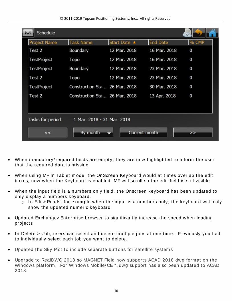
MAGNET users can now see all tasks assigned to them at once. In previous versions ofMAGNET Field you could only see the tasks you were assigned for the current project
o Dates are now shown below the days of the week in the mobile timecardo Added the ability to sort scheduled tasks by the Start Date, End Date, Task Name
and Project Name.
40
© 2011-2019 Topcon Positioning Systems, Inc., All rights Reserved
When mandatory/required fields are empty, they are now highlighted to inform the userthat the required data is missing
When using MF in Tablet mode, the OnScreen Keyboard would at times overlap the editboxes, now when the Keyboard is enabled, MF will scroll so the edit field is still visible
When the input field is a numbers only field, the Onscreen keyboard has been updated toonly display a numbers keyboard.
o In Edit>Roads, for example when the input is a numbers only, the keyboard will o nlyshow the updated numeric keyboard
Updated Exchange>Enterprise browser to significantly increase the speed when loadingprojects
In Delete > Job, users can select and delete multiple jobs at one time. Previously you hadto individually select each job you want to delete.
Updated the Sky Plot to include separate buttons for satellite systems
Upgrade to RealDWG 2018 so MAGNET Field now supports ACAD 2018 dwg format on theWindows platform. For Windows Mobile/CE *.dwg support has also been updated to ACAD2018.

41
© 2011-2019 Topcon Positioning Systems, Inc., All rights Reserved
Updated the Subscription notification so the user will be notified multiple times (daily)including the day of expiration for the final week of the subscriptio n
When connected to a HiperHR and TILT is enabled, we now store and display Tilt valuesand magnetic strength information with the compensated point in the raw data.
o Important for QC purposes
When connected to a HiperHR, the Battery Status is now displayed at External Battery andInternal Battery rather than Battery A and Battery B.
Added support for RTCM3 CS Oblique Mercator projection. This we added to better supportsome Leica Spider Networks that use the Oblique Mercator Projection
Added support for Tracking Galileo E5 and E6 signals o Support Galileo for positioning
Added quick access to Disconnect NTRIP MP in Topo and Stakeout. o Under M > Setup added Connect MP and Disconnect MP as options. The option
changes depending on whether you are currently receiving corrections.
Updated the TS target icons so you can easily identify when configured as a 360 deg prism
When importing points to an existing job, if the imported data has a point with the samename as an Occupation point in the current job, the user is now warned they will overwritetheir current occupation and if the user allows the point to be overwritten, MF willrecompute the job.
Added the option of ‘current time’ as a date/time attribute and is also the default time
Enhanced support for photos in a job. When photos are attached to the points in a job(photo notes) are now stored in the .mjf (MAGNET Job File). A built-in photo viewer hasalso been added so users can quickly view all photos in the job
Extend the Enterprise/Sitelink pages with ‘Use Proxy’ option that applies to Windows Proxysettings. This option will help with some users who could not perform an online activationdue to IT restrictions
Moved the Hybrid Positioning Connection checkbox to the Connection Screen.
In Hybrid mode, the RTK status Is now shown in the Optical Toolbar. You can also click onthe RTK status button to open the GNSS Status screens.

42
© 2011-2019 Topcon Positioning Systems, Inc., All rights Reserved
Updated the Controller Battery icon to indicate when the controller was plugged in andcharging.
Calculate
New Features/Improvements
Allow users to calculate the center point of a column by measuring one point on thecolumn and two HZ angles.
Added Vertical Deflection Angle value to the Calc Corner Angle report
Added a Closure report in Enter Plan that shows misclosures from the end of the last pointto the start point of the plan.
Added function of Session Check calculation to the Calculate menu to check GPS RTKSession data.
o This function was added to check every 2nd measurement of the same point.

43
© 2011-2019 Topcon Positioning Systems, Inc., All rights Reserved
Added the function to import session check data from the job (mjf, mjfzip, tsj, etc) fromanother field controller.
Configure
New Features/Improvements:
Equipment
Added support for Military (mil) angle units.
Updated the Backup settings and added the ability to do a ‘Full’ backup. The full backupstores your license, settings and the current job as well as options to include all jobs fromthe job folder.
In the Point Attributes screen, added the ability to Edit the Prefix/Suffix setting as well asadded a selector for ‘Increment Point Number’ so users can update the point increments.
Modified the output of RTCM3 MSM3 to minimize the size of the correction data messageto improve performance of some radios (Alinco)
Added support for Cyrillic keyboard
Added the GNSS Mission Planning icon to the Setup menu
MAGNET Field will now warn users if connected GNSS receiver is different than theselected configuration
Users can now set a limit to the number of Satellites used at the Relay Base.

44
© 2011-2019 Topcon Positioning Systems, Inc., All rights Reserved
Apply Base correction for all VRS Bases is now on by default
Added support for CSD (data call) for the HiperHR Base and Rover
Added ‘Correct Base’ to the Setup Menu for GNSS rovers
To simplify GNSS configurations, removed GLO P and L2C checkboxes and MAGNET Fieldnow always enable L2C if the Receiver OAF supports it. if the Receiver OAF does notsupport it, MAGNET Field will enable GLO P and only use if Use GLONASS is selected
Added the option when configuring the HiperHR for the Bluetooth Port option. This optionis often used as an option for NMEA
Added Point Properties to the first page of Survey Settings, so the user can change thepoint properties in the measurement screen
Added support for Spain/Vodafone M2M provider
Added support for RTCM message 1029 which is the NTRIP Operator Custom text message.
Added support for QZSS for RT DGPS, and works similar to other SBAS system support inMAGNET Field
Added the option in Project Settings to change the display slope values as either ratios oras a percentage.
o When defined as a ratio, you also have the ability to define the display values asX:1, 1:X.
Added Min SVs Setting in "Raw Data Logging to Controller".

45
© 2011-2019 Topcon Positioning Systems, Inc., All rights Reserved
Added new "External Ntrip Client" option to Survey Style view.o Support for a Dedicated Connection terminal for VRS is specifically for Japan.

46
© 2011-2019 Topcon Positioning Systems, Inc., All rights Reserved
Added the function of Station Prefix for Display in Configure. Users can choose between 3prefixes (No./Sta./SP.) as default.
Coordinate System

47
© 2011-2019 Topcon Positioning Systems, Inc., All rights Reserved
New Features/Improvements:
Coordinate Systems:
Added support for new Geoid model of Australia 2020 (AUSGeoid2010)
Added support for the New Zealand Geoid (2016)
Updated support for the Czech transformation correction table for the globaltransformation from ETRF to Czech CS
Added support for the Kansas Regional Coordinate System (KRCS)
Added support for the Russian State Coordinate system (GSK-2011) ellipsoid and datum
Added support for the Brazilian MapGEO 2015 Geoid
RTCM CS Oblique Mercator Support
Equipment
GNSS Enhancements
Added support for RTK TCP/IP for HIper HR
Added support for G5-A1 Antenna
Added support for the T-18 Field Controller
Added support for the MR-2 as a survey rovero External radios and external cell configurations supported
Updated support for the FH915 UHF radio module for so when configured for eitherNetwork RTK and Long Link, MAGNET Field will now Turn Off the radio .
Added support for FEC for internal Satel as well as external SRL-35 modem
Added Support for the SPX RD8000 cable finder
Added support for the Leica Disto D510/D810.
Added support for the DL-501 digital level

48
© 2011-2019 Topcon Positioning Systems, Inc., All rights Reserved
Added support a Japanese antenna parameter file.o The antenna parameter file was made official regulation by JSIMA.
mmGPS Support Enhancements
Added a new setup dialog for mmGPS.
Added Import/Export to/from job in Exchange for mmGPS calibration
Added the option in Job Setup to Import mmGPS calibration from the previous job
Added support for exporting mm Calibration data in a MAGNET Job (.mjf)_; and support forexporting mmGPS Calibration data to .tp3 files
Optical Enhancements
Updated support for the Ln-100 so when MAGNET Field is connected to the LN-100, iftracking to a prism is lost, the LN-100 will turn back to the design point location.
o Configure > Layout > Turn to Design Point
Added support for the GM/iM-50 manual total station
Updated support for the GM-100 and ES-60 to add support for reflective sheets
Exchange

49
© 2011-2019 Topcon Positioning Systems, Inc., All rights Reserved
New Features/Improvements:
New Formats Supported for Import/Export
Inframodel (IM3) Lecia HeXML 1.7 LandXML 1.2 and 2.0 (including Coordinate System Definitio n) LandXML 1.2 (Japanese Regulation) - This format is used for Japanese Public Construction
Work (i-Construction) Trimble TIN Model Files (*.ttm) CPIXML (FC-5000 Only) DLF Raw Data (export only) GeoPAK SOE (X-Sections) Bentley ICM iModel (including Roads and Surfaces)
Other Enhancements:
Added an option to export Background drawings
Added support for Lat/Long values in JPEG world file. Updated support for JPEG world filesand support Lat/Long in the world file where previously only Plane Coordinates weresupported.
Allow users to define the precision when exporting for Feet/Inches Added the filter ‘ Filter Stakeout Reports by Type’ when exporting stake reports
Added support for the import and export of custom projections.
Added the ability to assign descriptions from P3d as Codes. previously you could assigndescriptions as Notes only, but now have the option to assign descriptions as Codes ORNotes.
Added support for the Import and Export of X-Section data in SIMA format.
Added the option to Export areas by Layer. There are now two options for export byLayer:
o Areaso Lines and Areas when you select Multiple as the data type
When importing a text file with Full Codes from the global code library, on import, MF willnow use the Global Code library rather than create new codes

50
© 2011-2019 Topcon Positioning Systems, Inc., All rights Reserved
Added a ‘File Preview’ button in the Text Custom Formats Import/Export function. Thefirst rows of a file are displayed so you can see if the custom format is correctly defined forthe data in the file.
Added support when exporting FC6/GRS7 format files for the ‘created by’ field in theformat defition
Added support when exporting a LandXML file to include the job Coordinate System in thefile.
Added support to Import and Export CPIXML format files
Import/Export Wizard improvements. When selecting Multiple as the data type thefollowing options are available
o Select File Unitso Use Point Filter (by Layer or Code)o Select Point Typeso Filter lines by Layero Export areas as lineso Export GPS raw datao Export TS raw data
Updated the Import/Export User Interface to simplify the filter options.

51
© 2011-2019 Topcon Positioning Systems, Inc., All rights Reserved
o Allow the user to check different types of filters (by time, by range, etc) and thenshow the separate dialog for the filters that are selected
Updated the Import Export filter options to include more granular filters so the user caneasily export and import the data they want.
o Added the option to export ‘Today’ and 'Yesterday' to the filter optionso Added Date and Time Range filters as an option to 'Filter by Time'

52
© 2011-2019 Topcon Positioning Systems, Inc., All rights Reserved
Import from text/csv points if points with the same name are in the file and Data Type =Points/Multiple
o If users selects Data Type = Multiple, then import points with the same name asseparate points
Improved the ascii file import support to allow files with empty columns to still import andon import, MAGNET Field will skip the co lumns
Added support in Import/Export 3DMC Formats (tp3, pt3) for Codes as Notes option.
In Exchange History, added the status of ‘uploaded’ or ‘downloaded’ to the displayedattributes
Added the option when importing a *.dwg/*.dxf to import APL block points and all blockpoints
Updated the Export line/area function so lines and areas that are created by codes areexported to the layer they are originally on.
When importing data into a job the imported layers are tracked by name. if there is anexisting layer in the job with the same name, MAGNET Field now allow you to merge thelayers so you can continue to import into the already existing layer.
When you download a job from MAGNET Enterprise, the job is now, by default, downloadedto the MAGNET job folder on the controller.
Updated Job setup to allow users to:o Copy background drawings between jobs
o Copy surfaces between jobs
o Copy the last Backsight Setup to an existing job
o Added the ability to filter data by layer for import/export between jobs. This allowsthe user to move selected data between jobs.
o mmGPS Calibrations can be imported from the previous job.
Added support to export mm Transmitter calibration data to gc3 or tp3 files if needed.
Updated Export to LandXML format, and added a time stamp to the file
Updated Exchange From and To File and added a Most Recently Used section to the top ofthe file format list.
o Order Import/Export data format items according to the Most Recently Used.

53
© 2011-2019 Topcon Positioning Systems, Inc., All rights Reserved
o Save the top 4 recently used data types and separate them by a _____ so the usercan quickly find the most commonly used and not have to search the entire list.
o Maintain a separate Most Recently Used list for Import and Export
Added the ability to export GPS Offsets to the Topcon Custom GPS Formato Including: AzDist, Line, TwoDist, o Lazer offsets will be saved as Azimuth Distance Offsets
Updated support for importing a drawing as background, and if the imported file hasnamed points, MF will load the points in the job even if ‘Load as Background drawing’ isset
Added support for import of Codes from Hexagon LandXML.
Added ppm value as an option when exporting Topcon Custom TS (.txt).
Updated Exchange > Enterprise so if you have configured a Bentley ProjectWise repository,you can now see the repository when logged in from MAGNET Field
Added support for the import of Civil 3D COGO points.
Updated dwg support to support ACAD 2018 format on Windows (7/10) and CE/WM Fieldcontrollers.
Updated Import Linework so there are now separate checkboxes to allow the user toselect ‘load linework as background’ and ‘load points as background’
Added the option on point import to allow the user to select the layer that the points willbe placed on. Also added a shortcut to edit layers so you can create a layer beforeimporting the data.
When importing CAD files (DWG/DXF) allow users to select the layers they want to importfrom the file. Allows the user to import ONLY the data they need.
Added support to Export of Photo Notes for OpenRoads Survey (Bentley). o Support photo notes for SurvCE (.RW5) format
Extended the DLF raw data fomat and added QZSS/BeiDou Satellite support to the RawGNSS data format
Added support when importing *.dwg files to support ACAD Proxy Entities
In Exchange From File, MAGNET Field will now allow you to import points without Heightsand also points without North/East but with a Height so users can have height only pointsin the job.

54
© 2011-2019 Topcon Positioning Systems, Inc., All rights Reserved
Added the option to Import /Export X section sets from/to GeoPAK SOE format
Added support for the new format GNSS-Pro(DLF-file) for the output raw data.
MaXML Enhancements:
Updated MaXML to V1.1 with support of Custom projections/Stake Reports/Stake ReportsConfigurations/Quick Codes/mmGPS Calibrations and Field Report data types
Stakeout Report Configuration and Data Import/Export from/to MaXML format
Import/Export Reports with MaXML or MXLZIP
When point photo notes are exported to MaXML, the image file names are based on thecorresponding point names.

55
© 2011-2019 Topcon Positioning Systems, Inc., All rights Reserved
Edit
New Features/Improvements:
In Edit Points added the option to Sort by Nearest to the Sort by option list
Added ‘Layer’ to the columns shown in Edit points.
Added the option to select end edit multiple points in Edit Points. You can now selectmultiple points and edit Codes, Layer/Style and Notes

56
© 2011-2019 Topcon Positioning Systems, Inc., All rights Reserved
Added support in Edit Field Reports for Tiff and PNG formats when inserting an image
Updated Quick Code groups so they are now available across all jobs. MAGNET Fieldallows users to save QuickCode groups to the library in MAGNET Field and can be used inany job
In Edit > Point, renamed ‘Report Point’ to ‘Create Field Report’

57
© 2011-2019 Topcon Positioning Systems, Inc., All rights Reserved
Added a visual indicator to the photo tab in Edit > Points so the user can see if there arephotos attached to the point
Added the ability to Export points to field report under ‘M” > Edit Point
When points are measured with TILT they now have a unique icon so you can easilyidentify them in the job records
Enhanced Attribute support in MAGNET Fieldo Users to create required Attributes for Codes but no longer have to set a default
value. o Updated Attributes so users can now keep their list of Code Attributes in the order
they are created. In previous versions, the list would automatically alphabetiz e.
Updated point display in the Raw Data editor so when deleted points are displaye, they aremarked with a (x) mark before the point name. For Quality control, you can now seewhat points have been deleted from the job, and you can also restore the point if needed.
Under Edit > Surfaces, ‘Create Surface’ has been added as an option.
Added the column of “Session name” to Job info from [M] Menu in GNSS Raw Date table.o “Session name” info was added in Edit -> Raw Data -> Data.
Added the function to display RTK Session info from the measurement screen. "SurveySession' was added as a Data Label option.
Added the function of the importing session check data from the job (mjf, mjfzip, tsj, etc)by the other controller.

58
© 2011-2019 Topcon Positioning Systems, Inc., All rights Reserved
Deleted points are now shown in brackets in Edit > Raw Data
Job
New Features/Improvements:
Added the ability to attach scan files using 'Save Job As'.
Added Total Station FW version to the Job Info
Added support in Open/Save Job As for mxl/mxlzip/tp3 formats
Updated Create New Job to allow users to copy Quick Codes to a new job. You no longerneed to set up Quick Code groups with every job.
When a job is downloaded from MAGNET Enterprise that has the same name as an existingjob on the Field Controller, the job will be renamed to xxxxx(1). Where xxxxx is the nameof the job
Added support for ampersand (&) in a MAGNET Field job name
Added support for importing the last BS setup to an existing job. Previous support was toimport a backsight setup into a New Job ONLY
Enhanced the exchange of points between jobs.
With additional Filters to allow you to select the data you want

59
© 2011-2019 Topcon Positioning Systems, Inc., All rights Reserved
And select the points you want to copy to a job.
Added the option to do a Full Backup with options to store jobs and license. This featurecan be used to recover on the same or other controller during clean install
Map

60
© 2011-2019 Topcon Positioning Systems, Inc., All rights Reserved
New Features/Improvements:
Enhanced 3D Mode button options
o Solid + Wireframe has been added as a display option
o Updated the 3D mode navigation to allow easier rotation/panning/z ooming when in3D mode
o Added 3D Ortho Mode
o Background Drawings now supported in 3D Mode
o Switch map to North orientation with one click on the Compass
Increased the number of map data labels to 6 so the users can add additional live datapoints to the map screens
Added support for selecting a surface on the main map and added Stakeout, Edit, Deleteand Add to Layer features to the Rt Click when a surface is selected. When selectingobjects on the map, a Selection window will show that now includes surfaces. users canpick the surface they want to stake, edit, etc direction from the main map.
o Added the ability to select a surface on the map. o Added a map view to ‘select surface’ dialog.

61
© 2011-2019 Topcon Positioning Systems, Inc., All rights Reserved
Added support in the main map, to selecting an alignment (road) > stake road now bydefault stake the selected road.
When you have a Reference CL or Alignment selected, on the Stake Map we now show theReference Line highlighted on the map and only show the stationing on the Reference line.Set active road to map for all stakeout > road routines
Enhanced the import of CAD data and always import the data as a background drawing. Includes DXF, DWG, DGN, iModel). All points are also imported as regular points. Updated ACAD support to DWG2018 on the PC version and up to 2016 on the WM/CEversion of MAGNET Field
Added the view option ‘Solid + Wireframe’ and the option to colorize surfaces in the 3DMap properties options
Added a Map View to the Edit Layer dialog, so when a layer is turned on/off, the map viewwill reflect those changes.
Updated the Stakeout Map screen so the bottom of the Stakeout Map is nowsemi-transparent so the controls at the bottom of the screen no longer cover the map.
Added support in the map view for WMS tiles in 3D mode
Enhanced the Map Properties options so users can upload images and drawings inEdit>Background in Map Properties. The following types are supported: jpg, bmp, tiff,geotiff.
o Users can select uploaded items to display on the map in the map properties dialog/Background tab. The dialog shows a list with preview controls.
Updated the Drawings and Background user interface in MAGNET Fieldo In the Background tab implement control with options for Drawing, Images Map
Background + WMS layers Added the option to specify the WMS service(s) The Map + WMS Layers allow single selection map background source Control with checkboxes of available layers in the WMS. You can choose
layers from different WMS services In ‘M’ Context menu, added edit for Drawings, Images, WMS Added support for Virtual map files list to Map Properties Bing and WMS background maps are now supported in the 3D map

62
© 2011-2019 Topcon Positioning Systems, Inc., All rights Reserved
Added the Customized Map Toolbar as an option to all Survey, Stake and the Main Mapscreens. The customized toolbar allows the user to create a favorites menu of MAGNETfeatures that are specific to the way they work and allow the user to create customfavorites menus for both GNSS and Optical configurations. The Favorites configurationsare global so you create the custom configurations and use them across any job.

63
© 2011-2019 Topcon Positioning Systems, Inc., All rights Reserved
On the main map, users can now select multiple linework to create and build a surface. The entity selection options have also been updated to add the ability to select multipleentities in Area and Point List
Enhanced the ability to select lines and line segments. Users can no w select two separateline segments of the same line on the 2d and 3D map.
On the main map, when selecting ‘Center to Point’ the selected point is now highlighted onthe map

64
© 2011-2019 Topcon Positioning Systems, Inc., All rights Reserved
o Significantly improved the speed when selecting a point in a large jo b.
The Point symbol size has been updated to correspond to the user selected font siz e.
On the main Map the ‘join’ function has been added to the main map drawing toolbar.
Updated support for Cyrillic or Chinese text that is included in a ACAD DXF or DWG. Inprevious versions the text would be displayed as a box.
In 3D mode, the Pan option has been added to allow for easier navigation when working in3D mode
in 3D mode, the default view is now set so the observers position is now by default up ona slight angle to allow better viewing of the model when switching to 3D mode
Added support to allow users to Delete a Layer and at the same time, all of the data onthe layer. In Previous versions, you would first have to delete the data and then you coulddelete the layer
Enhanced the map view to only show the stationing for the active selected line.
Updated the 3D map to show linework with selected points the same as the 2D mapshows.
Setup
New Features/Improvements:
Updated the Benchmark routine to allow setting the benchmark by angle onlymeasurements. When the occupation point and target point Hz coords are known,MAGNET Field will use the point to point horizontal distance and measured vertical angleto compute slope distance and measured vertical angle to compute vertical distance.
Added ‘GNSS status’ to M > Setup > Backsight in Hybrid mode
A Receiver Management function has been added to the GNSS Setup feature and allowsyou to upload Reviver FW as well as get current OAF and Receiver Info (Including Serial

65
© 2011-2019 Topcon Positioning Systems, Inc., All rights Reserved
Number, Unique Board ID, Firmware version, OAF Expiration date )
o Users can now upload GNSS FW directly from MAGNET Field, as well as get currentOAF and Receiver Information and upload a Receiver OAF.
Survey
New Features/Improvements:
Updated support for Predefined Points in Set Collection
o The HR now changes to correspond with Target Type set
o Added a warning when measurements are out of the acceptable range and shows amessage to indicate ‘In Tolerance’ or Tolerance Exceeded. This allows the user toquickly decide if the observation results are within tolerance without having to go tothe results view.

66
© 2011-2019 Topcon Positioning Systems, Inc., All rights Reserved
Added the option to show Road Points to Survey > X-Section.
Added the ability to display the cross-section shape in the X-Section Window in the MapView. Users can check the shape of their cross section visually while in Survey > XSection
o Added the function to connect the cross-sectional observation point in X-Section.
Added the Pole cross-sectional observation option in Survey > X-Section.
Added the display option in Survey Map Labels (GNSS) to show Antenna offset height +HR when configured for Hybrid
In Point Attributes settings, add the option to ‘Store As’ with Prefix/Suffix and allow: None,Prefix, Suffix
In the Topo Map, the bottom control bar is now semi-transparent to provide additionalarea on the map.
Added the Quick Code groups list to the ‘M” Context menu, and you can now select theQuick Code group you want to use directly from the list.
Updated the Instrument status on the GNSS Toolbar when in Hybrid mode. Users can nowsee if they are still connected to the TS
In the GNSS Toolbar, RTK Quality has been replaced with RTK Age.
Added the ability to select the layer of the object separate from the code in Survey mode
o Layer selector (like Code selector) in Survey / Topo

67
© 2011-2019 Topcon Positioning Systems, Inc., All rights Reserved
Added support for Vertical search offset measurements when in Total Station mode. Whenusing Vertical Search, you first Measure the ferrule of the pole and then the secondmeasurement is to the center of the prism. For the second measurement you measurevertical angle and distance. The HA is stored from the pole measurement, and the VA andSD are by prism measurement.
o Vertical Search Offset is accessed from the M (menu) in Topo
Added the setting of 'Auto-Target' to the EDM button in Survey
In Topo Survey, moved the Point Properties setting to Configure > Point Naming for easeof access to the settings

68
© 2011-2019 Topcon Positioning Systems, Inc., All rights Reserved
Added a visual indicator to a dialog screen of the input mode. This indicator (icon) isreflected the change in BASIC Mode of Total Station. This feature was added for theJapanese Survey Market.
Stake
New Features/Improvements:
Reference Surfaces:
If you have a ref CL or Alignment selected, we now show the ref line highlighted on themap and only show the stationing on the ref line. Set active road to map for allstakeout > road routines
Added support for extending the reference surface in Stake Road, Real-Time Road andSlopes and Surfaces. Reference Surfaces can be extended perpendicular to a Reference

69
© 2011-2019 Topcon Positioning Systems, Inc., All rights Reserved
Alignment to allow users to extend the edge of an existing surface to hold the grade ofthe surface and extend to any distance.
Added the data label ‘Staked Count’ to the stake points screen. The label will display # o fpoints staked which shows the total number of points staked. If ‘include previous stakedoption’ is enabled, then the total count will include the prevous staked points.
o When Staking Grids, the total includes the points in the grids.
In the Map view, MAGNET Field will now show the HA even when not tracking the prism. The HA currently shows when tracking a prism.
Combined the Map and Normal view in Stake to show the navigation compass in the mapview.
o Deltas to the design point are shown in real time with the compass

70
© 2011-2019 Topcon Positioning Systems, Inc., All rights Reserved
Added the ability to display Road Points to all Road Functions. The user can select theRoad Points in BS Setup (by Station/Offset), X-Section Survey, Stake Road and StakeSlope.
Road Points are the Horizontal and Vertical transition points as defined along a Road.

71
© 2011-2019 Topcon Positioning Systems, Inc., All rights Reserved
Enhanced Drape Mode – added the feature of Drape Floor or Ceiling
o Users can now project a point to either the floor or ceiling Measure a point on the floor or ceiling to define the surface MF calculated the floor/ceiling plane Point is projected to the defined surface
In Stake > Points, users can now select the ‘next’ point to stake directly from the map,and do not have to return to the point list to select the next point.
Added data labels for: o Number of total/staked/not stake points
o Distance from the Occupation point to Current Position
o Added Left/Right data label for staking out a line with a conventional instrument
o Added the distance from the instrument to the prism in Stakeout. On large sites thiscan be helpful and also if there are more than 1 instrument on the site, the user willknow if they are receiving data from the correct instrument
Added the setting for Set Elevation tolerance in Configure > Layout. Previously the userwould have to configure the elevation tolerance in Stake Reports.

72
© 2011-2019 Topcon Positioning Systems, Inc., All rights Reserved
Added Setup > Reference Alignment option in Stake Surface. Users can select both aReference CL and Reference Alignment when Staking Roads, Surfaces, Grids, etc.
Added the option in Stake Map to select a design point on the map to stake.
When calculating 3D line lengths, the lines are now being draped to a surface when thereis a reference surface set.
When slope staking, the routine has been updated so the user will now get a distance tothe Catch Point even if they are not passed the Hinge Point. In previous versions, you hadto be past the Hinge Point to get a distance to the Catch Point.
Enhance Stake Grid so Next Nearest Point is on by default. This allows the user to startanywhere and proceed in any direction to the next point without having to use a Point List.
Added an option in stake surface to allow the user to define a plane with three points(from map/list/measure) and then stake the plane.
o Added plane offset to Stake Reports and as a Custom Map Label
Added MLM (missing line function) from Basic Mode to MAGNET Field. o Added the ability to select the method (A—B, A-C)/(A-B, B-C)
When staking a line, added the option to specify 2 end points to the slope stake routine.

73
© 2011-2019 Topcon Positioning Systems, Inc., All rights Reserved
Added the option ‘Extend Surface’ to all stake routines. The outside triangle(s) of theSurface will now be extended when using a Reference Centerline or Reference Alignment
When staking a offset line, in the map view, MAGNET Field will now show a dashed line tothe current offset point and the offset line being staked
Enhanced the Point to Line feature in MAGNET Field. The feature has been updated toallow a ‘line of sight’ direction to the line the surveyor is setting the point. Previously thepoint to line was calculated based on a perpendicular direction to the line.
When staking Surfaces and Roads, added an optional Cross Section view. In the Sectionview, the road element selected is highlighted. The Cross Section view is enabled in theMap Properties window in Stake.

74
© 2011-2019 Topcon Positioning Systems, Inc., All rights Reserved
Reports
New Features/Improvements:
Added an option to store Field and Stake Reports as a PDF in Landscape Mode
Added support in Photo Notes for the following formats: .jpeg, .png, .tif and .tiff
Resolved Issues
Resolved Issues:
On WM/CE Field Controllers the Calculate Area function would allow user to choose thewrong edge pt which resulted in wrong results
Addressed an issue when exporting multiple images to a file. Not all images would expo rtfrom the MAGNET Field job.
The recent Windows update 1709 would change the size of the the title bar and icons inMAGNET Field when the application was opened and closed, causing them to get smallerevery time the application was started.
Addressed an issue when a MAGNET Field job was using the Swedish projection and geoid. Changing geoid model does not change height of offset points.

75
© 2011-2019 Topcon Positioning Systems, Inc., All rights Reserved
Addressed an issue when importing *.KOF files into a MAGNET Field job. If the exportingsoftware used underscores instead of spaces between data fields the file would not importcorrectly.
When exporting raw data as Topcon Custom TS (*.txt), the offset was exported as metersonly.
Addressed an issue when exporting 2d lines to *.dwg format. if 'Use 3D coordinates' isturned off in the export wizard, 3d polylines were still exported as 3D and not as 2Dpolylines.
Addressed an issue in MAGNET Field support for Machine Control Systems. When the flag"Setup instrument for 3DMC" is set, the coordinates of station computation is correct, butthe backsight angle was incorrect. The incorrect backsight angle was then used in the LPSsetup. The correct backsight angle is now used in the setup.
Addressed an issue when reading the OAF info on the HiperHR. An incorrect ‘does notsupport L2C’ message was displayed.
Addressed an issue when switching between Hybrid and non-Hybrid modes. At times,after switching, the Hybrid adapter height would not be used in the measurement
Addressed an issue in the MAGNET Field Satellite tracking screens. Both Galileo andBeidou satellites were shown with a lock symbol in the Tracking screens even when thesatellite systems were turned off in the user interface. The tracking screen display hasbeen updated so when the satellite systems were disabled, they will not show in thetracking screens.
Updated Field and Stake Report generation so when MAGNET Field is configured forRussian, Cyrillic symbols are now properly displayed.
Updated the import of DXF files from HHK GEOgraf Software. When importing files witharcs, the arc would show as straight lines.
Addressed an issue when inserting TIF files as background Maps. At times, an unknownformat message was shown.
Addressed a crash in Stake when MAGNET Field was configured with the Swedishprojection and the background map was enabled. When staking a line, MAGNET Field attimes would crash.
Addressed an issue when exporting Stakeout reports and *.tvf format files. Deleted pointswould still export in the files.
Addressed an issue with photo image quality when using the FC-5000 Data Collector. The

76
© 2011-2019 Topcon Positioning Systems, Inc., All rights Reserved
1920x x 1080 images were being exported as 640 x x480.
Addressed an issue with RTCM3.1 message (1021) when using the SAPOSBaden-Wurttemberg reference network. The datum name was incorrectly displayed inMAGNET Field.
Addressed an issue when importing and displaying large drawing files in WM FieldControllers. Performance has been improved to allow large files to import and display.
Addressed an issue when importing TIFF files. Certain formats for TIFF files were notsupported.
Addressed an issue in the Remote Benchmark routine. The user now has the option tocreate a new point (Design Point) by checking the option when saving the Benchmarkmeasurement
Addressed an issue in Traverse Adjustment. When traversing through a BS point,previously the point would not be adjusted. With this update, the point is now adjustedwith the traverse.
Older GNSS receivers when connected to MAGNET Field would allow users to select Galileounder Tracking settings. If the GNSS receiver does not have the option (or support) forGalileo, the option is now greyed out.
Addressed an issue with Auto Tracking when using a RC4 and a QS Robot. Theautotracking icon would not respond and turn to the prism.
Addressed an issue when MAGNET Field/Layout was configured for Hybrid surveying andperforming a Hybrid Resection, the e-bubble would not show on the screen
Addressed an issue when configured for DGPS. In the Satellite status screen, no Satelliteswere displayed.
Addressed an issue when exporting RAW data to Leica GS18 and GS16 formats. Whenimporting the file(s) into a supporting application, the format was not recogniz ed.
When staking a line with the Stake setting set to Point = Range start and Note = Station &Offset, the note would only show the point numbers for the start and end point and did notstore the shot in the designated point range
Addressed an issue when storing a benchmark elevation. You could observe the point forelevation, but MAGNET Field would require a Northing and Easting to store the point.
Addressed an issue when importing Carlson CL files. If the file(s) contained a Statio nEquation, MAGNET Field would not import the file.

77
© 2011-2019 Topcon Positioning Systems, Inc., All rights Reserved
Updated the export of images for use in ESRI applications. The position was notembedded in the image, but instead show on the image. The position information is nowembedded in the image file.
Addressed an issue when connecting to a Trimble IBSS base station.
When staking points with zero or null elevation, at times, the Total Station would plungethe scope. This issue has been addressed and if the point does not have an elevation (oris Null), then the scope will use the default Vertical Angle o f 90 deg
Addressed an issue when the turning speed was set to 16 (default setting) on the LN-100. MAGNET Field would report a tilt error.
78
© 2011-2019 Topcon Positioning Systems, Inc., All rights Reserved
MAGNET Office 5.0.1
General
MAGNET Office V5.0.1 Release Notes
MAGNET Office 5.0.1 is an update for the following MAGNET Office products.
MAGNET Office Site
MAGNET Office Topo
MAGNET Office Layout
MAGNET 3D Exchange
MAGNET Tools
Magnet Tools
Fixed issue when exporting points to a *.csv file. Metric values were exported when coordinateunit set to US Feet.
Fixed issue with the least squares adjustment workflow. The Processing progress bar showed 'InProgress' after the adjustment was complete.
Magnet Office Site
Fixed issue with the display of arcs in the 3D View.
Fixed issue with line styles not being displayed in the Drawing Editor.
Fixed issue when printing to 100% scale to a physical printer.
Fixed issue with Least Squares Transformation scale input.
Fixed issue with symbol scaling when using symbol grips.
Fixed issue with Insert Text cursor not advancing with input.
Fixed issue with Slope Zone grid elevation display.
Magnet Office Topo
Fixed issue with the display of arcs in the 3D View.
Fixed issue with line styles not being displayed in the Drawing Editor.
Fixed issue with printing to 100% scale to physical printer.

79
© 2011-2019 Topcon Positioning Systems, Inc., All rights Reserved
Fixed issue with Least Squares Transformation scale input.
Fixed issue with symbol scaling when using symbol grips.
Fixed issue with Insert Text cursor not advancing with input.
Magnet Office Layout
Fixed issue with the display of arcs in the 3D View.
Fixed issue with line styles not being displayed in the Drawing Editor.
Fixed issue with printing to 100% scale to physical printer.
Fixed issue with symbol scaling when using symbol grips.
Fixed issue with Insert Text cursor not advancing with input.
Magnet 3D Exchange
Fixed issue with the display of arcs in the 3D View.
Fixed issue when printing to 100% scale to a physical printer.
Fixed issue with symbol scaling when using symbol grips.

80
© 2011-2019 Topcon Positioning Systems, Inc., All rights Reserved
MAGNET Office - V5.0
General - All Office Products
MAGNET Office V5.0 Release Notes
The following additions/revisions have been made to MAGNET Office v5.0
MAGNET Office Topo
MAGNET Office Site
MAGNET Office Modeler/Explorer
MAGNET Office Mass Haul
MAGNET Office Schedule
MAGNET Office Control
MAGNET Office Resurfacing
MAGNET Office Layout
MAGNET Office 3D Exchange
MAGNET Office Tools
Topcon Exchange for AutoCAD
Notes:
Magnet Office Site is required for Magnet Office Mass Haul and Resurfacing. Revisio nsand fixes applied to Magnet Site are included in Magnet Mass Haul and Resurfacingmodules.
Magnet Office Modeler is a new module automatically included in Magnet OfficeTakeoff and Mass Haul solution products. Modeler is a parametric modeling enginethat helps with converting 2D data into 3D and produce combined multi-disciplinarymodels from various input sources. Modeler supports BIM formats (LandXML, IFC) aswell as generic CAD formats.
o Magnet Office Explorer is included in Modeler. Explore is used for visualiz ation ofthe supported formats contained in Modeler.
Magnet Office Schedule and Control functionality (formerly DynaRoad Schedule andControl modes) is now automatically included in Magnet Mass Haul solution licenses.

81
© 2011-2019 Topcon Positioning Systems, Inc., All rights Reserved
o Schedule provides functionality to schedule required tasks for project completion.
o Control provides functionality to measure and compare on-site progress withplanned progress.
o Schedule and Control functionality is included only in the Magnet Mass Haulsolution.
Specific functionality additions, improvements, revisions and corrections are listed below perMagnet Office product.
New Features/Improvements:
General Improvements listed below are included in all MAGNET Office products unless otherwisenoted.
Improved UI to support Hi DPI (4K) monitors
Edit Points, located in the Modify ribbon, has been revised to include new filter,display, zooming, editing and entry capabilities. The UI has been updated to be amodeless interface which allows for the function to remain open while otherfunctions are being used. The interface can be set to auto hide, pinned, or docked tothe top, bottom or sides of the display.
Implemented new unified installation interface from MAGNET Field.
o New options for extracting cross section surface data.
o From Entities
o From PDF
o From Layers

82
© 2011-2019 Topcon Positioning Systems, Inc., All rights Reserved
o New filter options of Selection, By Entity, Layer and Layer group have been added.
o The grid display is configurable for content and order of content. Settings will beretained when changed.
o The grid allows for manual entry of x,y,z data for the creation and editing of points. Point deletion is also supported. Note: attention must be given to the updatelinework settings also provided in the grid area if deleting a point that is linked to anentity.
o The Edit Point interface and the Survey View are interactive. If a point or points areselected in the Survey view the grid rows for those points will be highlighted andvice versa.
o When a point is selected in the grid, the survey view will be updated to zoom to theselected point. The zoom level is determined by the zoom level set in the Surveyview. If you are zoomed in closely then the selected point will be zoomed to thecurrent zoom level. If multiple points are created a zoom level will be determined todisplay all of the selected points within the survey view simultaneo usly.
o If the Edit Points interface is open, whether set to autohide or pinned, points createdin the survey view by other functions will automatically be added to the edit pointsgrid. Note: if a filter has been applied then newly created points would need to bewithin the filter guidelines to be automatically added to the grid. An easy way toupdate the grid with all points is to set the All Layers filter as current.
Mirror is a new command located in the Modify Ribbon > Modify Ribbon group.
o This command with or without a pre-selection. Supported entities are Points, Lines,Arcs, Circles, Polylines, Strings, Polygons(Polygon, Boundary, lot, pad) andAlignment.

83
© 2011-2019 Topcon Positioning Systems, Inc., All rights Reserved
o After running the command and selecting the object, user will be prompted to definethe mirror axis. Mirror axis can be defined, by selecting two points on the surveyview, by selecting two locations in the survey view, by selecting a line from thesurvey view or by entering two point numbers in the input bar.
o User may also choose whether to keep the source object or not; by checking “Keepsource objects” checkbox in the input bar.
o If the “Keep source objects” checkbox is selected it will create new objects in themirrored location else it will move the selected object to the mirrored location.
File References is a new option located in the File ribbon > Standard ribbon group. Thisoption allows for referencing Autocad dwg and Bentley dgn files to a MAGNET Officeproject. Once referenced, the data from the file will be displayed in a light grey color. Theintent of this function is to use the attached files as references. Snap option are availablefor use with reference files for the purposes of measuring precise distances or for creatingentities if need from the reference file.
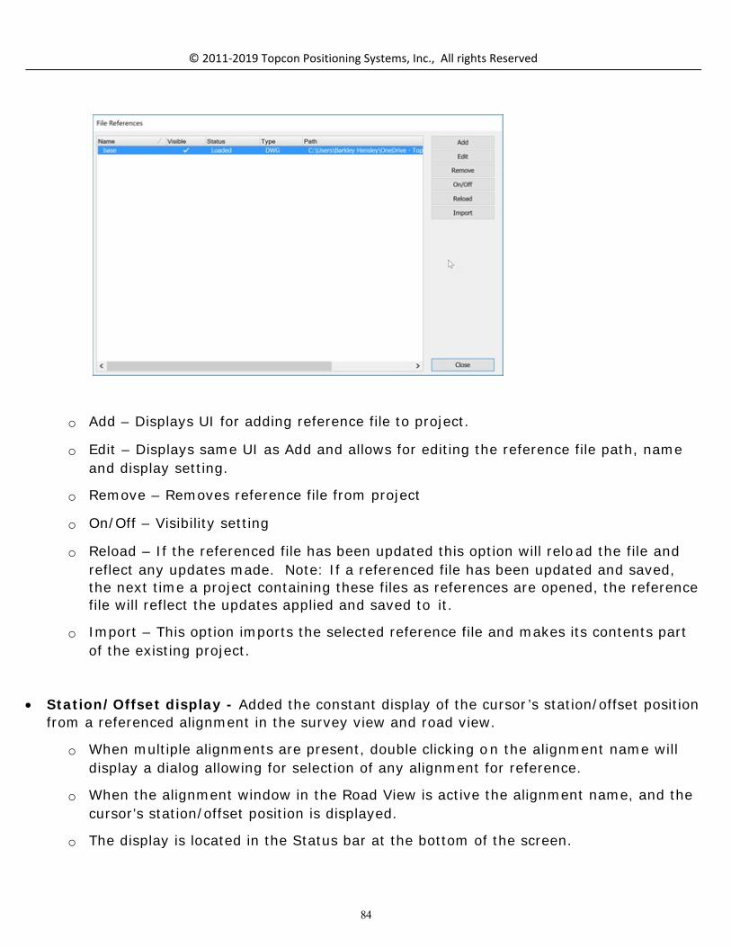
84
© 2011-2019 Topcon Positioning Systems, Inc., All rights Reserved
o Add – Displays UI for adding reference file to project.
o Edit – Displays same UI as Add and allows for editing the reference file path, nameand display setting.
o Remove – Removes reference file from project
o On/Off – Visibility setting
o Reload – If the referenced file has been updated this option will reload the file andreflect any updates made. Note: If a referenced file has been updated and saved,the next time a project containing these files as references are opened, the referencefile will reflect the updates applied and saved to it.
o Import – This option imports the selected reference file and makes its contents partof the existing project.
Station/Offset display - Added the constant display of the cursor’s station/offset positionfrom a referenced alignment in the survey view and road view.
o When multiple alignments are present, double clicking on the alignment name willdisplay a dialog allowing for selection of any alignment for reference.
o When the alignment window in the Road View is active the alignment name, and thecursor’s station/offset position is displayed.
o The display is located in the Status bar at the bottom of the screen.

85
© 2011-2019 Topcon Positioning Systems, Inc., All rights Reserved
Prompt for Elevation option has been improved to provide an option to turn off theprompt. Then the dialog is displayed the first time if the Prompt option is toggled off, theprompt will not return until turned back on. To turn the prompt on press ctrl+E to displaythe prompt dialog and toggle on the Prompt option.
Import/Export
o Added Bentley’s icm.dgn format for import/export.
o Direct import from Bentley Projectwise is available through MAGNET Enterprise DataManager. Use the Cloud Connection ribbon to logon to MAGNET Enterprise andselect the Bentley folder, or the name of the Bentley repository. Supported files canbe directly imported into the active MAGNET Office project, saved to a harddrive orboth.
o Direct export of the active project to Bentley Projectwise mapped folders is availablethrough MAGNET Enterprise Data Manager. For mapping of projects in MAGNETEnterprise please refer to the help section within Magent Enterprise.
Autocad 2018 dwg format is now supported.
o Import dwg has been improved to support Autocad xrefs when attached to the filebeing imported

86
© 2011-2019 Topcon Positioning Systems, Inc., All rights Reserved
o Import dwg has been improved to include the option to import linework as
breaklines. The option is located in the Import Settings options on convert Autocad
dialog displayed during import.
MAGNET Field, Field Reports are now supported in MAGNET Office. Field reports arelocated in the Survey Ribbon within MAGNET Office.
When MAGNET Field jobs containing field reports are imported into MAGNETOffice, the field reports will be available for display.
Field reports are included in the export to MAGNET Field jobs.
Field reports are displayed by selecting the field report icon in the Surveyribbon.
Pdf files can be created by using the Save as PDF option.
TP3 files:
o Import added the option to import point descriptions as either notes or codes inMAGNET Office.

87
© 2011-2019 Topcon Positioning Systems, Inc., All rights Reserved
o Export to TP3 has been updated to include the option to export MAGNET Office pointcodes or notes as descriptions.
o Points without names will now use the next available point number in MAGNETOffice.
Infamodel3 has been added to the import/export options.
Added import/export support for SBG GEO and PXY files.
o Note: when exporting a SBG (*.LIN) file 3 files, (LIN/PRF/SEC will be created.
Import of LandXML files containing road design data and multiple surfaces has beenupdated to import all surfaces. A prompt for selection of the surface to use as the“Design” surface in the road view has been added.
Control Points has been improved to support the import of ASCII text files.
Added new option to Export 3D pdf from the Survey view, 3D Toggle view or 3D Tab view.This file can be opened in a pdf viewer and viewed in 3D.
o To export as 3D PDF toggle on the option highlighted above.
o Export Inactive Data will export all data in the project that is not being displayed atthe time of export.

88
© 2011-2019 Topcon Positioning Systems, Inc., All rights Reserved
Import ASCII text files has been updated to provide an option to ignore surveycodes. This option will import the data on the active layer in the project and ignoresurvey codes for linework and property definitions.
o Note: the Update Survey option contained in editors such as the SpreadsheetEntry Editor, Raw Data Editor, Traverse Editor will also provide the option toignore survey codes.
Added new option, Insert String by multiple points to the Insert Ribbon, Stringgroup. This option allows for the pre selection of point to join by individual orwindow selection. The connection order options consist of by nearest point orselection order.
The Follow option available from the right mouse button menu has been improvedto support polylines. The follow option will follow existing polylines between thespecified entry and exit locations. Tip, use End point snap to ensure correctlocations.
Modify, Segment Line has been improved to work on multiple lines simultaneously.
Select by Points has been improved to select points irrespective of the code. It isnow possible to select a mixture of points with and without codes.
o Added a new check box to the select by points tab code section. If uncheckedthe search will be done regardless of the code setting.
MAGNET Site, Topo and Layout

89
© 2011-2019 Topcon Positioning Systems, Inc., All rights Reserved
MAGNET Office Site, Topo and Layout
New Functionality and Improvements
Command Aliases the optional command line has been improved to dock at the bottomof the screen and remains active when opened. This allows for the entry of commands bytyping short cut codes for commands.
o Use the Command Aliases option to define existing commands by short cuts. Forexample the Modify copy command may be defined as CO. Available commands fordefinition are listed in the command aliases.
o The command line is turned on by pressing the space bar.
o Auto hide is available for use with the command line.
o Plotting has been improved to support transparency settings for backgroundimages.
o Added new option to Insert Polyline by multiple points to the Insert Ribbon,Polyline/Polygon group.
o Added new option to Insert Polygon Area by multiple points to the Insert Ribbon,Polyline/Polygon group
Fixed Issues
Corrected issue with the Pan command in the Drawing Editor causing intermittent programcrash.
Corrected issue when printing a project containing a background image with a rotatedorientation to a pdf file. The resulting pdf file placed the background image in the wro ngposition.
Corrected issue with the Clipping option in Polygon Area and Boundary functions. Clippingwas not consistently clipping out entities.
Corrected issue with North arrow scale when opening older jobs containing drawings.
Corrected issue with option “Create Layer from source layer” when exporting from thedrawing editor to AutoCAD dwg. The “suffix” option was not working.

90
© 2011-2019 Topcon Positioning Systems, Inc., All rights Reserved
MAGNET Site and Topo
MAGNET Office Site and Topo
New Functionality and Improvements
Improved printing Cut/Fill maps to pdf. Resulting pdf file size has been reduced.
Annotation has been update to include support for entities that do not contain points.
o Entities created with the “Create Point” setting turned off in the Settings ribbon arenow available for annotation.
o Entities that have had their points deleted using the Delete Points from Entity o ptionin the Modify ribbon can also now use the annotation toggle.
o Annotations are updated if the entity is changed by direction or distance.
Compare Points has been updated to add new options for comparison. The command islocated in the Inquiry ribbon. The function now allows for:
o Added definition of base points to compare by options:
All Data
Active Layers
Current Selection
Points (user specified by number)
Entity (user selected)
o Added definition of target points or surface for comparison options.
Data within current project
Points (user defined or All)
DTM (surface)
Data within another job (project must be open)
Points
DTM
o X,Y,Z tolerance settings are required to generate a report. Note: When base pointshave multiple points within the tolerance settings, each point compared with the

91
© 2011-2019 Topcon Positioning Systems, Inc., All rights Reserved
base points will be listed on individual lines. For example if base po int 1 has fourcompared points within the tolerance settings, point 1 will have four rows of datalisted.
o Optional Label Elevation Difference settings are provided. If Label Elev Diff to ggle ischecked, the elevation difference will be inserted for the point as text in thespecified layer. Note: if the Cut/Fill label option is toggled on in the report options,the elevation difference will be reported with a “C” or “F” prefix as well labeled thesame within the project.
o Multiple report options have been provided. Note: when using Excel as an externaleditor, toggle ON the option of Excel Format to have the data separated into columnswithin Excel.
Tie DTM is a new option located in the Surface Ribbon > DTM Tools > that ties one dtm toanother by user defined slope.
o Extrapolate side slopes is used when you want to extend existing side slopes of asurface to another surface. This option uses the outer triangle slopes and extendsthem to the reference surface.
DTM Shading has been improved to default to a two color shading scheme from lowest tohighest elevation. The legacy shading scheme is still available and can be accessed fo ruse by selecting the “advanced” button in the Edit DTM dialog.

92
© 2011-2019 Topcon Positioning Systems, Inc., All rights Reserved
Insert Perpendicular Line has been improved to add the option to interpolate theelevation of the created points from the active DTM. Toggle on the Interpolate from DTMoption on the status bar.
Insert Parallel Line has has been improved to add the option to interpolate the elevationof the created points from the active DTM. Toggle on the Interpolate from DTM option onthe status bar.
A new Create Entity interface has been implemented for quick creation of different typesof entities. The function is in the Insert ribbon, entity group.
o The following entity creation is supported:
Points, lines/arcs, strings, polygon areas, boundaries, polylines, lots, and pads. Select therequired entity from the type dropdown
o Coordinate data can be entered manually, or locations picked from the graphicwindow within the interface
o Creation of entities by direction and distance is supported.
o Creation of entities by point number is supported. Point numbers may be entered invarious ways. Example points defined for creation of a string using 1-10,35,45,57-62 will create a string starting at point 1 continuing sequentially through po int10, then connect to points 35 and 45 then continue sequentially to point 57.
o Point property settings of use in surface and elevation on/off are readily available.
Note: if elevation option is toggled on until the elevation is entered or theelevation toggle turned off, the elevation field will have red shading indicating

93
© 2011-2019 Topcon Positioning Systems, Inc., All rights Reserved
that input is required.
o Prompt for properties of the entities being created can be turned off. When ON thenormal property dialog for the entity being created will be displayed.
o To create an entity, once the entity is defined either select the create entity optionfrom the right mouse click menu or select the insert button.
o Right click context menus are provided for each entity supported.
o Use the Add button to add existing points during entity creation.
o Use the Back button to remove the previous entity segment or point creation.
o Use the update button to save changes to point coordinate data or property data.
If changing a coordinate of a point the update button must be used to applythe changes. Entities containing this point will then be updated if applicable.
o All point or x,y,z data used in the creation of an entities is displayed in the grid areaof the interface.
Edit Entity is a new option for editing entities. Using this option not only will theproperties, color, layer etc be available for edit but also the coordinate data for the pointsused to create the entity.

94
© 2011-2019 Topcon Positioning Systems, Inc., All rights Reserved
o Edit Entity is located in the Modify ribbon as well as the Insert ribbo n in the.
o When an entity is selected the appropriate edit dialog will be displayed. Selecting a string will display available edits for a string, selecting a lo t willdisplay the edit lot options etc.
o Once the interface is active, selecting entities in the project will auto maticallychange the entity type and provide the available data for edit. There is noneed to shut down the interface to select a different type entity, simply selectthe next entity to edit.
o Entity types can be quickly converted as well. Simply select an entity, thetype will be automatically set for the entity, to convert the entity simply selectanother type from the dropdown.

95
© 2011-2019 Topcon Positioning Systems, Inc., All rights Reserved
o If the elevation option is on and there is no value in the elevatio n field, thefield be shaded red and you will not be able to proceed until the elevatio n isentered or the elevation toggle turned off.
o Use the Insert option to insert a point into an entity. The selected point will beadded between the two nearest points on the entity.
o Use the Update option to apply coordinate changes to a point contained withinthe entity.
o Use the Remove option to remove any point contained in the entity.
Note: The Insert and Remove options are when selected place theroutine in that state until selected again. If the insert option is selectedinsertion of points into the selected entity will continue until the insertbutton is selected again. Remove works in the same way.
To access certain properties of an entity, the Prompt for Properties toggleshould be on.
Background Images now supports import of GeoTiff files.
o Multiple GeoTiff files can be inserted simultaneously by selecting the files to impo rtin the dialog displayed when running the Background image command.
o The Background Image command is found in the Insert Ribbon, Image/PDF options.
Cross Sections from DTM has been improved to create cross sections from multiplesurfaces simultaneously. The previous setting of “Additional Sections” has been removedand the fuctionality combined with the new Multiple Surfaces option.
o Toggle on the Multiple surfaces option
o Fill out the XS from DTM settings, press next
o Fill out or select next to the additional cross section dialog
o Fill out the Surfaces dialog to include the surfaces that sections are required on.
Define the surface type for each surface cross section.
o View cross section in the Road view by opening the alignment used for sectiongeneration.
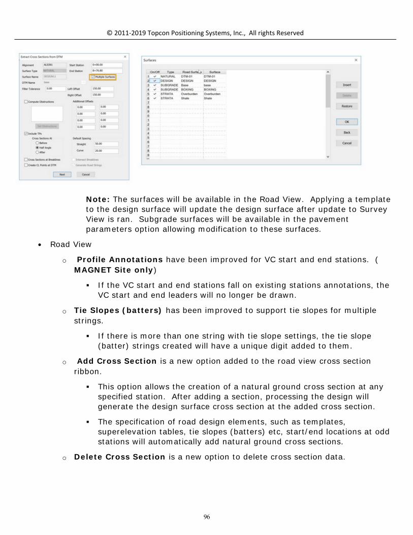
96
© 2011-2019 Topcon Positioning Systems, Inc., All rights Reserved
Note: The surfaces will be available in the Road View. Applying a templateto the design surface will update the design surface after update to SurveyView is ran. Subgrade surfaces will be available in the pavementparameters option allowing modification to these surfaces.
Road View
o Profile Annotations have been improved for VC start and end stations. (MAGNET Site only)
If the VC start and end stations fall on existing stations annotations, theVC start and end leaders will no longer be drawn.
o Tie Slopes (batters) has been improved to support tie slopes for multiplestrings.
If there is more than one string with tie slope settings, the tie slope(batter) strings created will have a unique digit added to them.
o Add Cross Section is a new option added to the road view cross sectionribbon.
This option allows the creation of a natural ground cross section at anyspecified station. After adding a section, processing the design willgenerate the design surface cross section at the added cross section.
The specification of road design elements, such as templates,superelevation tables, tie slopes (batters) etc, start/end locations at oddstations will automatically add natural ground cross sections.
o Delete Cross Section is a new option to delete cross section data.

97
© 2011-2019 Topcon Positioning Systems, Inc., All rights Reserved
Resolved Issues
Data Clean-up has been revised to correct an issue with Delete Duplicate points. Not all duplicates were being deleted.
Corrected issue with Horizontal Alignment Report incorrectly reporting the Bearingvalues for bearing in and out of arc segments.
Fixed issue with Boundaries named with lowercase letters not being recognized whenusing the Select by Region.
Corrected issue with negative stations (chainages) not plotting in profile (longsection) and cross section plots generated from the Road View.
Corrected issue with calculating peg chainage around turning points of an alignment.Some projects displayed invalid peg chainage alert. alert.
MAGNET 3D Exchange
MAGNET 3D Exchange
Added Merge DTM option. This option provide functionality to merge five DTMs surfacessimultaneously.
DTM Shading has been improved to default to a two color shading scheme from lowest tohighest elevation. The legacy shading scheme is still available and can be accessed fo ruse by selecting the “advanced” button in the Edit DTM dialog.
Added new option, Insert String by multiple points to the Insert Ribbon, String group.This option allows for the pre selection of point to join by individual or window selection. The connection order options consist of by nearest point or selection order.

98
© 2011-2019 Topcon Positioning Systems, Inc., All rights Reserved
Resolved Issues
Data Clean-up has been revised to correct an issue with Delete Duplicate points. Not allduplicates were being deleted.
MAGNET Office Topo
MAGNET Office Topo
Added a Cul-de-sac design interface. Located in the Design Ribbon, Subdivision group,this routine creates a cul-de-sac based on selected center point and offset strings.
MAGNET Office Site
MAGNET Office Site
New Features and Improvements:
Corridor functionality has been added to MAGNET Office Site only. Corridor can beused to design multiple design requirements of a site or road project. The intent ofthe corridor functionality is to aid in the recreation of design plans. All elements o f acorridor design are interlinked so that changes made to any design element willupdate the corridor design. New horizontal and vertical alignment editors have been included as well as a newtemplate editor. Zones have been introduced as part of the corridor functionality. Using Zoneswidths and Zone slopes any station along the horizontal alignment can quickly andeasily be modified and the corridor design updated.

99
© 2011-2019 Topcon Positioning Systems, Inc., All rights Reserved
All editors alignment, template and zone widths/slopes are all modeless; meaningthat all editors can be opened simultaneously while functionality from the surveyview, main CAD view, is still accessible.
Create Corridor is used to defines the elements to be used for the creation of thecorridor.
o Corridor Name
o Horizontal Alignment Name
o Vertical Alignment Name
o Reference Surface
o Layer for offset strings
o Design DTM name
Corridor Settings is used to change any setting defined when creating the corridor.
Rename/Delete Corridors is used to rename or delete existing corridors.
Save as Corridor as Road Design can be used to save the H/V alignments and roadtemplate used in the corridor so that the data can be opened and used in the road view.
o Note: Only the road template used in a corridor design will be transferred to theroad view. Side templates, used in corridor design are not transferred to the roadview. In addition complex templates which may be defined in the corridor templateinterface may not correctly transfer to the road view.
Create Alignment creates a horizontal alignment that can be used in any corridor design.
Alignment Editor is used for both creation and edit of horizontal and vertical alignments.The editors can be used independent of corridors but also can be used to specifically workwith alignments assigned to corridors. When an alignment is selected in the editor thathas been included in a corridor, the corridor name will be displayed and the verticalalignment assigned to the corridor will be loaded in the vertical alignment tab.
Horizontal Alignment Editor

100
© 2011-2019 Topcon Positioning Systems, Inc., All rights Reserved
Vertical Alignment Editor
Create/Edit Templates is used to define or edit templates used in a corridor design.There are two types of templates Road and Side.
o Road templates are used typically to define the roadway from shoulder toshoulder.
o Side templates are used to define areas outside of the roadway shouldersthat are referenced to the horizontal alignment stationing. Side templates canbe used to define simply tie slopes to the reference surface or complex designsincluding ditches, varying side slopes, benching etc. Side templates are defined for both the left and right side of the roadway. If a

101
© 2011-2019 Topcon Positioning Systems, Inc., All rights Reserved
2:1 slope is required as the slope to the reference surface, one side templatedefining a 2:1 side slope can be used for the left and right sides of the road. The program will correctly apply the slope in cut and fill and in the co rrectdirection pertaining to the side of the road which it is applied.
o Template Types represent the definition for the template leg being defined.There are multiple options when defining template types.
Offset/Slope – defined by horizontal distance and slope. The templateleg created extends at the defined slope until the defined offset distanceis reached.
Offset/Rel. Elev. – defined by horizontal distance and relative elevationvalue (difference in elevation) from the relative to point.
Offset/Abs. Elev. – defined by horizontal distance and absoluteelevation.
Slope Rel/ Elev. – defined by horizontal distance and relative elevation(difference in elevation) from the relative to point.
Slope/Abs. Elev. – defined by slope and absolute elevation. Thetemplate leg created is created by extending the defined slo pe until itreaches the absolute elevation specified. 5% to elevation 1200 forexample.
Side Slope – defined by a slope value and used to tie to reference DTM;typically used in Side templates. If the start of this template type is infill the slope will go down to tie to the reference surface and vice-versa ifin cut. Applicable if corridor has a reference surface defined.
Side Slope/Offset – defined by an offset distance. The templatesegment extends to the horizontal distance intersection with the corridorreference surface. Applicable if corridor has a reference surface defined.
Bench – defined by slope, bench width and height. Benches will becreated either going up or down, depending on if in cut or fill, at thedefined slope specified between benches until the reference surface isintersected. Applicable if corridor has a reference surface defined.
Reference String – define by a relative to string. selected string usedin design. Template segments (types) can be defined to a referencestring that has been added to a corridor. Reference strings can also beused as a relative to definition in the template. Required for use of ZoneWidths and Slopes.
Slope/Intersection – defined by slope from specified “relative to”setting intersecting at specified template segment name.

102
© 2011-2019 Topcon Positioning Systems, Inc., All rights Reserved
Connect/Intersection – this option will connect two template segmentnames at a specified intersection name.
Template Type Conditions
Cut – template type will be applied only if the last templatesegment was in a cut area.
Fill - template type will be applied only if the last templatesegment was in a fill area.
Note – If the condition field is blank, the template segment will becreated under all conditions, regardless of whether the lastsegment was in cut or fill
Template Editor
o Edit Template Rt Panel area.
Corridor – corridor name
Section – template type either Road or Side
Settings – user defined settings for DTM/String creation.

103
© 2011-2019 Topcon Positioning Systems, Inc., All rights Reserved
Subgrades – underlying materials that make up subgrades can be created in thetemplate editor. Subgrade surfaces copy the slope of the design surface betweentwo specified corridor template strings or reference strings. The depth of thesubgrade is defined by the entering the depth of the subgrade in the thickness datafield. The thickness can be referenced to the design surface or another previoussubgrade. A subgrade reference surface must be specified for correct setting of thethickness.

104
© 2011-2019 Topcon Positioning Systems, Inc., All rights Reserved
Insert, Delete, Previous and Next buttons are used to insert and deleterows in the Station/width grid and to advance or back up to rows within thegrid.
Insert At inserts a station at the cross-section indicator in the survey view.
< and > icons advance the cross-section preview by the step spacing settinglocated in the settings dialog.
Template Library provides access to three template libraries, Global, Project andCorridor. Templates that are typical and required for later access can be created in theglobal library. Templates can be transferred from/to global, project and corridor libraries.
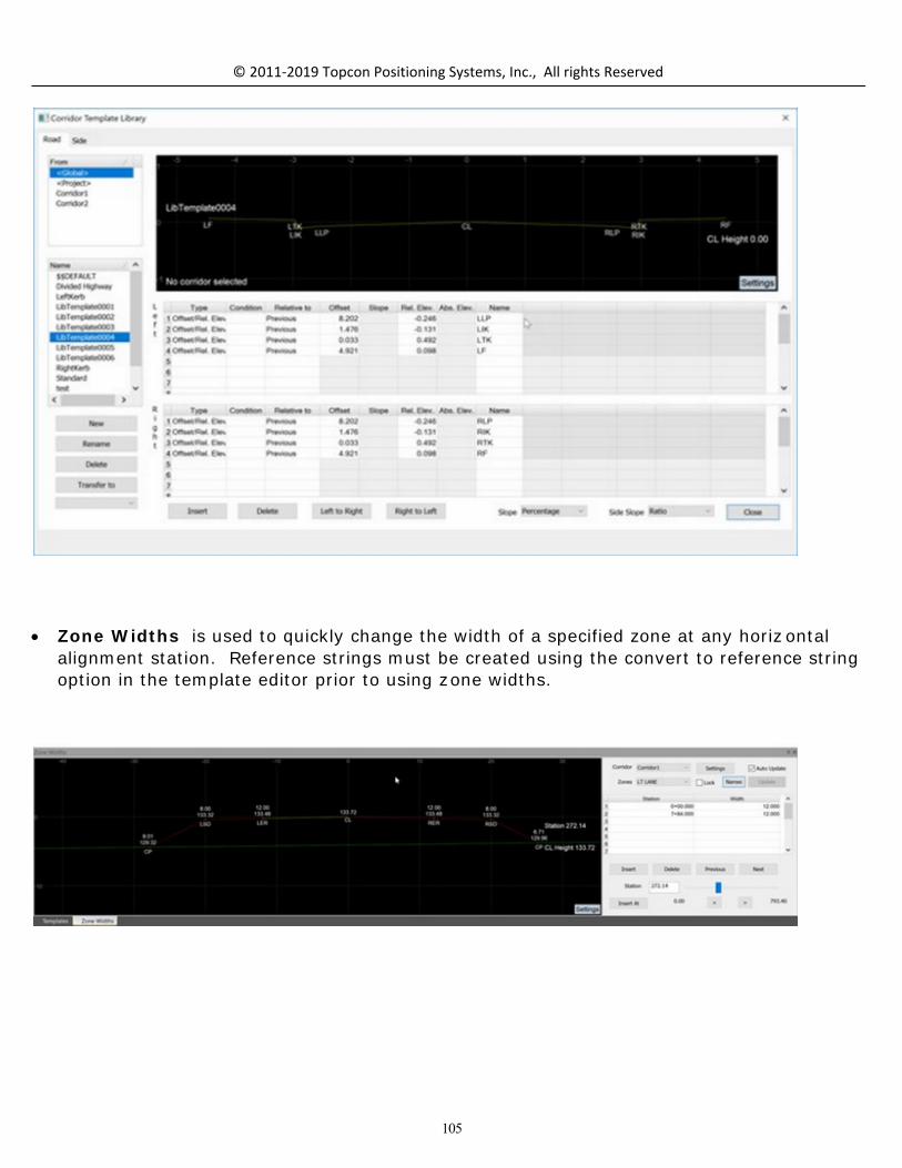
105
© 2011-2019 Topcon Positioning Systems, Inc., All rights Reserved
Zone Widths is used to quickly change the width of a specified zone at any horiz ontalalignment station. Reference strings must be created using the convert to reference stringoption in the template editor prior to using zone widths.

106
© 2011-2019 Topcon Positioning Systems, Inc., All rights Reserved
Zone Slopes is used to quickly change the slope of a specified zone at any horizontalalignment station. Reference strings must be created using the convert to reference stringoption in the template editor prior to using zone widths. The UI for Zone Slopes is the same UI used for Zone Widths but specific to slopes atspecified stations.
Fixed Issues
Corrected issue with when applying a template to a profile/curb string. The templatestrings were only applied to one side.
Corrected issue with some road strings generated in road design not having the elevationflag turned on. Strings such as verges (shoulder extensions), ditches and compound sideslopes (batters) created when updating the survey view from the road view resulted intheir point elevation flag not being turned on.
MAGNET Office Resurface

107
© 2011-2019 Topcon Positioning Systems, Inc., All rights Reserved
MAGNET Office Resurface
New Features and Improvements:
Add Cross Section is a new option that allows for adding a cross section anywhere alongthe design alignment.
o The cross section will be added based on the distance specified from the active orspecified station.
o A negative value is entered in the distance field if a cross section is required befo rethe reference station.
A new option Show/Hide Strings has been added to the Features group in the CrossSection ribbon in the resurface design interface.
Under Mill Shading has been added as a new display option in the resurface designinterface plan view window. To display under milling areas toggle on the Under-millingarea option in the resurface settings dialog.
Jump to Station has been added to the Plan View within the Resurface design interface.This option allows for the user to “Jump” to the nearest station to a selection point of astring. There are three options for using the jump station option.

108
© 2011-2019 Topcon Positioning Systems, Inc., All rights Reserved
o Click the Right Mouse Button (RMB) select Jump to Station and pick a location onany string to jump to the nearest cross section station.
o While pressing the Ctrl button pick on a string to jump to the nearest cross sectionstation.
o Use the draggable station marker (color cyan) to indicate the current station.
o Profile and cross section windows will update dynamically with the change in
stations.
The Cross Section window has been improved to interactively update as the stationindicator line is moved in the profile pane.
The Start/End Mark functionality has been improved to automatically flip the start andend marks if the end mark is moved to a position before the start mark. Historically whenthe end mark was moved in front of the start mark, this would result in the start markbeing moved to a position in front of the alignment start station.
Insert String is a new option that has been added to the Design ribbon of the resurfacedesign interface. This option allows for the insertion of a new string based on specifiedoffsets from a selected reference string.
Slope Graph in the long section (profile) window has been improved. The graph area isnow resizable and is based on a user entered percentage of the long section window.
o The slope graph settings are found in the Settings ribbon, Resurface tab.
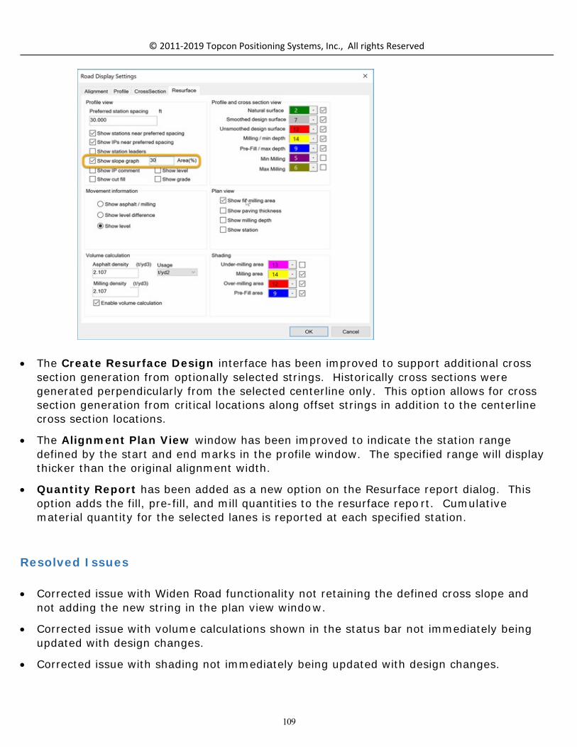
109
© 2011-2019 Topcon Positioning Systems, Inc., All rights Reserved
The Create Resurface Design interface has been improved to support additional crosssection generation from optionally selected strings. Historically cross sections weregenerated perpendicularly from the selected centerline only. This option allows for crosssection generation from critical locations along offset strings in addition to the centerlinecross section locations.
The Alignment Plan View window has been improved to indicate the station rangedefined by the start and end marks in the profile window. The specified range will displaythicker than the original alignment width.
Quantity Report has been added as a new option on the Resurface report dialog. Thisoption adds the fill, pre-fill, and mill quantities to the resurface repo rt. Cumulativematerial quantity for the selected lanes is reported at each specified station.
Resolved Issues
Corrected issue with Widen Road functionality not retaining the defined cross slope andnot adding the new string in the plan view window.
Corrected issue with volume calculations shown in the status bar not immediately beingupdated with design changes.
Corrected issue with shading not immediately being updated with design changes.

110
© 2011-2019 Topcon Positioning Systems, Inc., All rights Reserved
Corrected issue with Average Level option when using variable interval stationing.
o Note: the method for calculation of average level has changed. The new methodmay take longer to process but yields much more accurate results.
The Alignment window (plan view) in the resurface design UI has been updated to correctan issue with the data display. All data was not being displayed when the Display SurveyData option was On in the Alignment pane settings.
MAGNET Office Takeoff
MAGNET Office Takeoff
Improvements
Improved speed of creating Strata DTMs.
Takeoff Total Site calculations and DTM creation has been improved to temporarily resolvecrossing breaklines resulting from breaklines created both in the design layer gro up andsubgrades. Crossing breaklines are temporarily converted to individual segments duringvolume and subgrade dtm creation. Subgrade breaklines are given highest prio rity duringtotal site volume and dtm creation. Note: this applies to Takeoff Total site calculationsonly and not the Create DTM command.
Resolved Issues
Borehole entry has been revised to correct an issue allowing the creation of a boreholewithout entering strata data.
Borehole entry has been revised to correct an issue with a borehole being created atcoordinates of 0,0 when the Insert/Edit borehole dialog was closed.
Resolved Issues - All Office Products

111
© 2011-2019 Topcon Positioning Systems, Inc., All rights Reserved
Resolved Issues:
Corrected issue with entering negative elevations when units are set to feet and inches. Negative elevations without a feet value were being converted to positive elevations.
Corrected issue for points containing no elevation when exported to TP3 file resulting inpoints containing incorrectly referenced elevations. Elevation values were listed as 1.#Q0 ’for example. Points with no elevation are now exported to TP3 files as points withelevation zero (0).
Corrected Import of LandXML files created in GeoPak SS4 not importing station equationsfor horizontal alignments.
Corrected issue with Point names containing spaces not being supported in Control Points. Control Point names can now include spaces.

112
© 2011-2019 Topcon Positioning Systems, Inc., All rights Reserved
MAGNET Tools - V5.0
General
MAGNET Office Tools
New Features and Improvements:
Installation of shell extensions for Windows Explorer to communicate with hardware is nowoptional.
Improved UI to support Hi DPI (4K) monitors.
Coordinate Systems:
Added Geocentric Datum of Australia 2020 (MGA2020)
Added New Zealand geoid 2016
Add Swedish geoid SWEN17 for RH70 and RH2000
Added Russian State Coordinate system GSK-2011

113
© 2011-2019 Topcon Positioning Systems, Inc., All rights Reserved
Added Kansas Regional coordinate system
Added RTCM3 CS Oblique Mercator support.
Added display of geoid reference datum in Geoid list.
Import/Export
Added import/export of Bentley icm.dgn format.
o Direct import from Bentley Projectwise is available through MAGNET Enterprise DataManager. Use the Cloud Connection ribbon to logon to MAGNET Enterprise andselect the Bentley folder, or the name of the Bentley repository. Supported files canbe directly imported into the active MAGNET Office project, saved to a harddrive orboth.
o Direct export of the active project to Bentley Projectwise mapped folders is available
through MAGNET Enterprise Data Manager. For mapping of projects in MAGNET
Enterprise please refer to the help section within Magent Enterprise.
Added new option Import Photo Notes in the Job ribbon, Exchange ribbon group.
o This option imports a photo note or multiple photo notes simultaneously and assignsthem to points.
o The Auto Assign option will automatically assign photo notes to points based onGPS coordinates if present in the image file.
Added support for Import of GSI 8 and GSI 16 formats.

114
© 2011-2019 Topcon Positioning Systems, Inc., All rights Reserved
Added support for LandXML 2.0 import/export
Added support for export of GNSS data to Star*Net.
Traverse Adjustment
Updated TS (total station) traverse adjustment to support compass rule adjustmentregardless of the direction of traverse, clockwise or counter clockwise.
Reorganized the table of measurements for TS traverse reports.
Reports:
Added Tilt parameters to the GPS Occupation report.
Added EDM and Prism Mode to the TS Observation report.
Miscellaneous:
Event marker support improvements
o Added option to Import event markers into the GNSS post processing log file fromexternal text file.
o Added option to view existing event markers for a GNSS occupation with the abilityto edit time delay (offset) and delete events.
o Added option to Export event markers to text file.
Revised Post Processing engine options to use only the BaseLine PP engine forpost-processing.
Added support for using Web Mapping Services (WMS) maps as background image in theView ribbon, Spatial group.

115
© 2011-2019 Topcon Positioning Systems, Inc., All rights Reserved
Added Point Coordinate Sets tab in the point properties dialog. Each coordinate has aquality shown that indicates the source action that produced the coordinates. Allcoordinates generated after operations such as post processing, adjustment, check shotsetc are displayed.
Added the display option for Depth in the GPS Observation tabular view. This is in suppo rtof depth sounding applications.
Added option to switch UI language directly from within MAGNET Tools. From the helpribbon select the Language icon and select language. Changing the language will initiate arestart of MAGNET Tools.
Added MAGNET Enterprise connection status and connected project in the bottom rightcorner of the status bar. When connected to MAGNET Enterprise the icon will displayOnline, when connected to a project Online will be replaced with the project name.

116
© 2011-2019 Topcon Positioning Systems, Inc., All rights Reserved
MAGNET Exchange for Autodesk
General
MAGNET Exchange for Autodesk
New Features and Improvements:
Program has been updated to reflect a name change from Topcon Exchange for Autocad toMAGNET Exchange for Autodesk.
Added the option to directly import MAGNET Field *.mjf files from MAGNET Enterprise intoCivil 3D.