maesflo tm user manual - fluigent · vertical pointer slide. slide the pointer to change or adjust...
TRANSCRIPT

Page - 1
FLUIGENT Siège social : BIOPARK -1 mail du Pr. Georges Mathé – 94800 Villejuif - France
Tel : +331 77 01 82 68 – Fax : +331 77 01 82 70
www.fluigent.com
SA à Directoire et Conseil de Surveillance au capital de 59.380,70 € - Siret : 487 636 409 00038 – N°TVA UE/EU VAT Number : FR 53 487 636 409
MAESFLOTM
User Manual
for version 3.1.3
Version 15/07/2013

Page - 2
FLUIGENT Siège social : BIOPARK -1 mail du Pr. Georges Mathé – 94800 Villejuif - France
Tel : +331 77 01 82 68 – Fax : +331 77 01 82 70
www.fluigent.com
SA à Directoire et Conseil de Surveillance au capital de 59.380,70 € - Siret : 487 636 409 00038 – N°TVA UE/EU VAT Number : FR 53 487 636 409
Table of contents
1. INTRODUCTION ......................................................................................................... 4
2. SYSTEM REQUIREMENTS ........................................................................................... 5
3. INSTALLATION INSTRUCTIONS ................................................................................... 5
4. HOW TO START ......................................................................................................... 6
4.1 Material needed for pressure control ......................................................................................................... 6
4.2 Material needed for Flow-Rate Control Module ...................................................................................... 6
4.3 Starting MAESFLOTM ........................................................................................................................................... 6
5. MAESFLOTM
PRESSURE CONTROL PANEL (EXPANDED) ................................................ 7
6. MAESFLOTM
PRESSURE CONTROL PANEL (CONTRACTED) ............................................ 8
7. WORKING WITH SEVERAL MFCSTM
AND MFCSTM
-EZ.................................................... 9
8. GRAPHS DISPLAY AND FLOW-RATE PANEL ............................................................... 10
9. LIST OF KEYBOARD SHORTCUTS ............................................................................... 11
10. MOUSEWHEEL CAPTURE ADDON ......................................................................... 12
11. MAESFLOTM
PARAMETERS DIALOG ....................................................................... 13
11.1 System Information (MAESFLOTM parameters dialog) ....................................................................... 13
11.2 Add FLOWELL (MAESFLOTM parameters dialog) .................................................................................. 14
11.3 Configurations (MAESFLOTM parameters dialog) ................................................................................. 14
11.4 Record (MAESFLOTM parameters dialog) ................................................................................................ 15
11.5 Feedback coefficients (MAESFLOTM parameters dialog) ................................................................... 15
12. FLOW-RATE CONTROL MODULE: OPERATING PRINCIPLE ...................................... 16
12.1 Pressure for flow-rate control ..................................................................................................................... 17
12.2 Reachable flow-rate ........................................................................................................................................ 17

Page - 3
FLUIGENT Siège social : BIOPARK -1 mail du Pr. Georges Mathé – 94800 Villejuif - France
Tel : +331 77 01 82 68 – Fax : +331 77 01 82 70
www.fluigent.com
SA à Directoire et Conseil de Surveillance au capital de 59.380,70 € - Siret : 487 636 409 00038 – N°TVA UE/EU VAT Number : FR 53 487 636 409
12.3 Flow-rate priority ............................................................................................................................................ 18
12.4 Identification step ............................................................................................................................................ 19
13. IDENTIFICATION WIZARD ..................................................................................... 20
13.1 Overview ............................................................................................................................................................. 20
13.2 Create a new system setup ........................................................................................................................... 21
13.3 Load an existing system setup ..................................................................................................................... 26
13.4 Enter manually the parameters (Advanced user) ............................................................................... 28
14. MAESFLOTM
FLOW-RATE CONTROL PANEL ............................................................ 33
14.1 Overview ............................................................................................................................................................. 33
14.2 Panel description ............................................................................................................................................. 33
14.3 Buttons description ......................................................................................................................................... 33
14.4 Right click controls .......................................................................................................................................... 35
15. MAESFLOTM
PARAMETERS DIALOG FOR FLOW-RATE CONTROL MODULE .............. 36
15.1 Flow-rate configurations ............................................................................................................................... 36
15.2 Flow-Rate Control Module ............................................................................................................................ 36
15.3 Identification File Viewer ............................................................................................................................. 39
16. FLOW-RATE CONTROL MODULE AND PRESSURE CONTROL INTERACTIONS ........... 40
17. FREQUENTLY ASKED QUESTIONS .......................................................................... 41
17.1 How to start ........................................................................................................................................................ 41
17.2 Create a new system setup ........................................................................................................................... 41
17.3 Load an existing system setup ..................................................................................................................... 42
17.4 Enter manually the parameters (advanced user) ................................................................................ 43
17.5 MAESFLOTM Parameters dialog for Flow-Rate Control Module ....................................................... 44
Page - 4
FLUIGENT Siège social : BIOPARK -1 mail du Pr. Georges Mathé – 94800 Villejuif - France
Tel : +331 77 01 82 68 – Fax : +331 77 01 82 70
www.fluigent.com
SA à Directoire et Conseil de Surveillance au capital de 59.380,70 € - Siret : 487 636 409 00038 – N°TVA UE/EU VAT Number : FR 53 487 636 409
1. Introduction
The MAESFLOTM
software is a software solution for microfluidic flow control. Used with the MFCSTM
-EZ and the
MFCSTM
pressure actuators, the MAESFLOTM
provides a quick, stable and accurate control of up to sixteen (16)
pressure channels. By adding the FLOWELL flow-rate measurement solution, the MAESFLOTM
enables high
resolution monitoring of up to six (6) flow-rates in your microsystem(s). Combining the MFCSTM
-EZ or the
MFCSTM
and the FLOWELL performances with a new algorithm (Flow-Rate Control Module), the MAESFLOTM
has
become the solution for providing accurate and fast flow-rate control. Now the MAESFLOTM
gives you the
option to precisely and smoothly control microfluidic flows by pressure orders, flow-rate orders or both of
them while keeping benefits of pressure actuation.
The MAESFLOTM
user manual describes how to use the MAESFLOTM
for your day-to-day work. It describes all
the MAESFLOTM
functionalities that will help you to perfectly control your microsystem(s). Explanations about
the Flow-Rate Control Module operating principle are provided as well as answers to frequently asked
questions. You will then be able to make the most of the MAESFLOTM
performances and features.

Page - 5
FLUIGENT Siège social : BIOPARK -1 mail du Pr. Georges Mathé – 94800 Villejuif - France
Tel : +331 77 01 82 68 – Fax : +331 77 01 82 70
www.fluigent.com
SA à Directoire et Conseil de Surveillance au capital de 59.380,70 € - Siret : 487 636 409 00038 – N°TVA UE/EU VAT Number : FR 53 487 636 409
2. System Requirements
This installation requires one of the following Microsoft operating systems:
• Windows XP Service Pack 3
• Windows Vista x86
• Windows Vista x64
• Windows 7 x86
• Windows 7 x64
This installation requires that version 3.1 of the MSI (Windows Installer) Engine is installed on your computer. If you
do not have MSI 3.1 or later, the installer updates the engine automatically and might require that you restart your
computer.
The MAESFLOTM
software requires:
• A minimum of 512 Mo of RAM (2Go recommended)
• Minimum processor Intel Pentium 1.6 GHz
• Minimum screen size 800 x 600
3. Installation Instructions
Before installing the MAESFLOTM
software, log on as Administrator or as a user with Administrator privileges. The
MAESFLOTM
software setup program must have Administrator privileges because the program modifies the
configuration registry of your system. Complete the following steps to install the MAESFLOTM
software:
1. Plug your MAESFLOTM
USB key. The installer launches if your USB key plays data automatically. If the
installer does not launch automatically, navigate into the USB key files using Windows Explorer and launch the
setup.exe file from your MAESFLOTM
software USB key.
2. The installation wizard guides you through the necessary steps to install the MAESFLOTM
software. You can
go back and change values where appropriate by clicking the Back button. You can exit the setup where
appropriate by clicking Cancel.
3. When the installation is complete, click Finish.

Page - 6
FLUIGENT Siège social : BIOPARK -1 mail du Pr. Georges Mathé – 94800 Villejuif - France
Tel : +331 77 01 82 68 – Fax : +331 77 01 82 70
www.fluigent.com
SA à Directoire et Conseil de Surveillance au capital de 59.380,70 € - Siret : 487 636 409 00038 – N°TVA UE/EU VAT Number : FR 53 487 636 409
4. How to start
4.1 Material needed for pressure control The FLUIGENT devices below are needed for starting the MAESFLO
TM software. All the devices must be
connected to your computer.
• At least one (1) MFCSTM
-EZ or one (1) MFCSTM
. Up to four (4) MFCSTM
-EZ or (1) MFCSTM
and (1) MFCSTM
-EZ
or two (2) MFCSTM
can be used.
• Optional: up to two (2) FLOWELL for flow-rate monitoring.
4.2 Material needed for Flow-Rate Control Module The FLUIGENT devices below are needed for starting the Flow-Rate Control Module. All the devices must be
connected to your computer.
• At least one (1) MFCSTM
-EZ or one (1) MFCSTM
. Up to four (4) MFCSTM
-EZ or (1) MFCSTM
and (1) MFCSTM
-EZ
or two (2) MFCSTM
can be used with the Flow-Rate Control Module.
• At least one (1) FLOWELL. Up to two (2) FLOWELL can be used with the Flow-Rate Control Module.
• A dongle key supplied by FLUIGENT.
4.3 Starting MAESFLOTM
Click on the MAESFLO
TM shortcut on your desktop to launch the MAESFLO
TM with pressure control features
(and flow-rate monitoring if available).
Click on the Display menu and select the Flow-Rate Control Module option to launch the Flow-Rate Control
Module. The Display menu is available on the Pressure Control panel.
Frequently asked questions (see § 17.1)
All the FLUIGENT devices needed are connected to my computer but the Flow-Rate Control Module option is
still disabled.

Page - 7
FLUIGENT Siège social : BIOPARK -1 mail du Pr. Georges Mathé – 94800 Villejuif - France
Tel : +331 77 01 82 68 – Fax : +331 77 01 82 70
www.fluigent.com
SA à Directoire et Conseil de Surveillance au capital de 59.380,70 € - Siret : 487 636 409 00038 – N°TVA UE/EU VAT Number : FR 53 487 636 409
5. MAESFLOTM
Pressure Control panel (expanded)
*: Requires Flowell
**: Requires FRCM Dongle
The Pressure Control panel provides you with the following
functionalities:
1. Vertical pointer slide.
Slide the pointer to change or adjust the requested
pressure on the given channel.
2. Manual pressure control.
Directly enter the requested pressure on the given
channel. See Configurations (MAESFLOTM
parameters
dialog) for navigation keyboard shortcuts to control the
pressure order.
3. Measured pressure.
Display the current pressure on the given channel.
4. Limit.
Set the maximum pressure on a given channel if
necessary for your experiment
5. Channel coupling.
Easily link the channel pressure settings between several
channels by selecting the appropriate coupling label in the
drop down menu.
When channels are coupled with “A+”,
increasing/decreasing the pressure of one channel will
increase/decrease the pressure of the other(s) channel(s)
of the same amount.
When two channels are coupled with “A-”, increasing the
pressure of one channel will decrease the pressure of the
other channel of the same amount.
6. Unit selection.
Select the pressure unit you want to use from the drop
down menu (mbar, psi and Pa).
7. Channel naming.
Right-click to change the channel names.
8. Display options.
Select from the drop down menu additional windows
(pressure graph, flow-rate panel*, flow-rate graph*, Flow-
Rate Control Module**) you want to display

Page - 8
FLUIGENT Siège social : BIOPARK -1 mail du Pr. Georges Mathé – 94800 Villejuif - France
Tel : +331 77 01 82 68 – Fax : +331 77 01 82 70
www.fluigent.com
SA à Directoire et Conseil de Surveillance au capital de 59.380,70 € - Siret : 487 636 409 00038 – N°TVA UE/EU VAT Number : FR 53 487 636 409
6. MAESFLOTM
Pressure Control panel (contracted)
1. Contract/Expand main window.
Let you contract or expand the main window so that you can respectively, trim
the panel to the menu and access to the entire panel.
2. Access to MAESFLOTM
parameters.
See MAESFLOTM
parameters dialog for more details.
3. Recording.
Log the set pressures, measured pressures, and measured flow-rates* at a
given sampling rate. See Record (MAESFLOTM
parameters dialog) for more
details.
4. Configurations.
Save the current pressure configuration of the different channels (by clicking
on the “Config P” button).
5. Configuration list.
Select the configuration you want to apply.
6. Zero pressure.
Set all pressure channels to zero. Pressing “Escape” key will also set all
pressures to zero.
7. Control (ON/OFF).
When control is set to OFF, no new order is sent to the MFCSTM
-EZ or MFCSTM
but the monitoring and recording are still working. When control is set to ON
orders are transmitted to the MFCSTM
-EZ or MFCSTM
.
8. MFCS status.
Display the current connection status of the MFCSTM
-EZ – PC or MFCSTM
– PC
communication.
When using only MFCSTM
(without any MFCSTM
-EZ), the purge button will be
available.
Purge
Set maximum pressure available in channel 1. The maximum pressure available
corresponds to the pressure value displayed in the front panel of the MFCSTM
.

Page - 9
FLUIGENT Siège social : BIOPARK -1 mail du Pr. Georges Mathé – 94800 Villejuif - France
Tel : +331 77 01 82 68 – Fax : +331 77 01 82 70
www.fluigent.com
SA à Directoire et Conseil de Surveillance au capital de 59.380,70 € - Siret : 487 636 409 00038 – N°TVA UE/EU VAT Number : FR 53 487 636 409
7. Working with several MFCSTM
and MFCSTM
-EZ
It is possible to control up to four (4) MFCSTM
-EZ or one (1) MFCSTM
-EZ and one (1) MFCSTM
or two (2) MFCSTM
with MAESFLOTM
.
You can then control up to 16 pressure channels and mix control of positive and negative pressure and/or
control of low and high pressure.
When several MFCSTM
-EZ or MFCSTM
are connected to the same computer you are asked to choose which
pressure actuator you want to control with MAESFLOTM
(example below with 4 MFCSTM
-EZ).
All pressure channels of all the MFCSTM
-EZ are then displayed in the main control window.

Page - 10
FLUIGENT Siège social : BIOPARK -1 mail du Pr. Georges Mathé – 94800 Villejuif - France
Tel : +331 77 01 82 68 – Fax : +331 77 01 82 70
www.fluigent.com
SA à Directoire et Conseil de Surveillance au capital de 59.380,70 € - Siret : 487 636 409 00038 – N°TVA UE/EU VAT Number : FR 53 487 636 409
8. Graphs Display and Flow-rate Panel
Pressure Graph window:
Display pressure measurements of the different
channels in % of full scale.
This window can be rescaled.
You can choose which pressure channel you want
to display by clicking on the corresponding box.
Flow-rate Graph*
window:
Display flow-rate measurements of the different
channels in % of full scale.
This window can be rescaled.
Flow-rate Panel*:
1. Flow-rate measurement.
2. Start/stop volume measurement.
3. Reset volume measurement.
4. Volume measurement.
5. FLOWELL serial number. Up to 2
FLOWELL can be simultaneously
displayed.
6. FLOWELL connection status.

Page - 11
FLUIGENT Siège social : BIOPARK -1 mail du Pr. Georges Mathé – 94800 Villejuif - France
Tel : +331 77 01 82 68 – Fax : +331 77 01 82 70
www.fluigent.com
SA à Directoire et Conseil de Surveillance au capital de 59.380,70 € - Siret : 487 636 409 00038 – N°TVA UE/EU VAT Number : FR 53 487 636 409
9. List of keyboard shortcuts

Page - 12
FLUIGENT Siège social : BIOPARK -1 mail du Pr. Georges Mathé – 94800 Villejuif - France
Tel : +331 77 01 82 68 – Fax : +331 77 01 82 70
www.fluigent.com
SA à Directoire et Conseil de Surveillance au capital de 59.380,70 € - Siret : 487 636 409 00038 – N°TVA UE/EU VAT Number : FR 53 487 636 409
10. MouseWheel Capture addon
The MouseWheel Capture addon allows you to take control of the pressure channel from the mouse wheel.
You need to select the Pressure channel you want to control then you will be able to increment/decrement the
pressure order with the mouse wheel.
The MouseWheel Capture dialog should be active and your mouse pointer within the window bounds to run
the capture.
Pressure Panel:
By right-clicking on pressure channels, you can
have access to the MouseWheel Capture dialog.
MouseWheel Capture:
This window appears when clicking on
MouseWheel Capture menu item.
You can choose the pressure channel you want to
control by directly clicking on the corresponding
box or using the Tab shortcut.
Once the channel is selected and only when the
MouseWheel Capture window is active and your
mouse pointer is within this window (see the green
indicator), you are able to change the pressure
value while moving the mouse wheel.

Page - 13
FLUIGENT Siège social : BIOPARK -1 mail du Pr. Georges Mathé – 94800 Villejuif - France
Tel : +331 77 01 82 68 – Fax : +331 77 01 82 70
www.fluigent.com
SA à Directoire et Conseil de Surveillance au capital de 59.380,70 € - Siret : 487 636 409 00038 – N°TVA UE/EU VAT Number : FR 53 487 636 409
11. MAESFLOTM
parameters dialog
Select Parameters to display this dialog box.
Use this dialog box to set MAESFLOTM
parameters. You can customize the appearance and operating mode of
MAESFLOTM
and add devices to MAESFLOTM
software.
• Category: List the parameter options to customize the appearance and operating mode of MAESFLOTM
.
Select an option in the Category list box to display the parameter options in the dialog box.
• System Information: Information on your hardware used into MAESFLOTM
.
• Configuration: Set options for configuration files.
• Record: Set options for log files.
• Add FLOWELL: Add FLOWELL devices to MAESFLOTM
software.
• Flow Rate Control Module: Control the Flow-rates in your microfluidic system.
• Feedback coefficients: Set options for pressure feedback coefficients.
11.1 System Information (MAESFLOTM
parameters dialog)
Summary of hardware used into
MAESFLOTM
software.

Page - 14
FLUIGENT Siège social : BIOPARK -1 mail du Pr. Georges Mathé – 94800 Villejuif - France
Tel : +331 77 01 82 68 – Fax : +331 77 01 82 70
www.fluigent.com
SA à Directoire et Conseil de Surveillance au capital de 59.380,70 € - Siret : 487 636 409 00038 – N°TVA UE/EU VAT Number : FR 53 487 636 409
11.2 Add FLOWELL (MAESFLOTM
parameters dialog)
1. List of connected FLOWELL (Shift-
click selects multiple FLOWELL).
2. Number of selected FLOWELL. Up
to 2 FLOWELL can be used with
MAESFLOTM
.
3. Refresh. If your FLOWELL is not
automatically detected press this
button.
11.3 Configurations (MAESFLOTM
parameters dialog)
Configurations are a snapshot of a
pressure set point. You can name
your different configurations, create
shortcuts and choose to display them
or not in the drop-down menu of the
main panel.
1. Folder path: You can choose the
path for the directory containing your
configurations. Default path is
C:\Fluigent\Maesflo\Config.
2. Name: Display the configuration
name of the configuration saved in
the Folder path directory. Ticking a
configuration will display it in the
drop-down menu of the main screen.
3. Shortcut: You can set and use
shortcuts (with F1 to F9 keys) for
direct access to configurations.

Page - 15
FLUIGENT Siège social : BIOPARK -1 mail du Pr. Georges Mathé – 94800 Villejuif - France
Tel : +331 77 01 82 68 – Fax : +331 77 01 82 70
www.fluigent.com
SA à Directoire et Conseil de Surveillance au capital de 59.380,70 € - Siret : 487 636 409 00038 – N°TVA UE/EU VAT Number : FR 53 487 636 409
11.4 Record (MAESFLOTM
parameters dialog)
You can log pressure orders,
measured pressures and flow-rates of
your experiments at anytime.
1. Record file path: You can choose
the path of the log file location.
Default path is
C:\Fluigent\Maesflo\Record\.
2. Record period: You can choose the
sampling rate between three preset
values. This sampling period is
indicated on the main panel
(expanded version).
11.5 Feedback coefficients (MAESFLOTM
parameters dialog)
With this parameter you can set the pressure response shape.
The factory default value is 5.
Response mode:
If the feedback coefficient is higher
than 5 the response is faster but you
can also have overpressure and
instability.
If the feedback coefficient is lower
than 5 the response is more stable
without overpressure but it will lead
to a slower response.
Note: It’s highly recommended to
not change the default value. The
MFCS™-EZ has been optimized by
Fluigent experts and should provide
you with the best compromise
between stability and fast response.
Please contact us for more information: [email protected]

Page - 16
FLUIGENT Siège social : BIOPARK -1 mail du Pr. Georges Mathé – 94800 Villejuif - France
Tel : +331 77 01 82 68 – Fax : +331 77 01 82 70
www.fluigent.com
SA à Directoire et Conseil de Surveillance au capital de 59.380,70 € - Siret : 487 636 409 00038 – N°TVA UE/EU VAT Number : FR 53 487 636 409
12. Flow-Rate Control Module: Operating principle
The Flow-Rate Control Module uses pressure actuation to control flow-rates. As shown in the figure below,
applying pressure in the suitable FLUIWELLTM
reservoirs creates a liquid flow through your microsystem. As
both pressure and flow-rate are measured by the MFCSTM
-EZ or the MFCSTM
and the FLOWELL, the Flow-Rate
Control Module is able to automatically adjust pressure(s) to reach the flow-rate set-point(s). This operating
principle enables to control complex microsystems made up of coupled channels. The Flow-Rate Control
Module may be used with up to sixteen (16) pressure channels and six (6) flow-rate channels. Combining with
MFCSTM
-EZ or MFCSTM
, and FLOWELL, this solution provides fast, stable and precise flow-rate control.
To perform flow-rate control by pressure actuation, the Flow-Rate Control Module needs to create a model
containing the relations between pressures and flow-rates. This is done thanks to the identification step. This
step must be successfully achieved to access flow-rate control features. Besides, the flow-rate control
performances are impacted by the flow-rate measurements relevance and the pressure channel selected.
During the experiment, the model is continuously computed to check any variation and adapt its response (in a
certain range).
All these points will be discussed below and we will give you practical examples and advice to make the most of
the Flow-Rate Control Module performances.

Page - 17
FLUIGENT Siège social : BIOPARK -1 mail du Pr. Georges Mathé – 94800 Villejuif - France
Tel : +331 77 01 82 68 – Fax : +331 77 01 82 70
www.fluigent.com
SA à Directoire et Conseil de Surveillance au capital de 59.380,70 € - Siret : 487 636 409 00038 – N°TVA UE/EU VAT Number : FR 53 487 636 409
12.1 Pressure for flow-rate control The choice of the pressure channels used for the flow-rate control has a key impact on the Flow-Rate Control
Module performances. In this part, we will introduce the pressure channel and pressure range selection.
The figure on the left describes a simple
microfluidic set-up. The input is connected
to the pressure and flow-rate channels 1.
The output is connected to the pressure and
flow-rate channels 2. A "positive" flow-rate is
given by the arrow direction on the left
scheme for each flow-rate channel.
We will describe the Flow-Rate Module
Control behavior in two different cases:
Case 1: Only the pressure channel 1 is controlled by the Flow-Rate Control Module. In this case the Flow-
Rate Control Module will only provide positive flow-rates. To obtain negative flow-rates, the
pressure in channel 2 has to be increased. As this pressure has not been selected for the Flow-Rate
Control Module, you have to increase the pressure manually. Then, the Flow-Rate Control Module
will be able to reach negative flow-rates.
Case 2: The pressure channels 1 and 2 are both controlled by the Flow-Rate Control Module. In this case,
the Flow-Rate Control Module will automatically adapt the pressure of both pressure channels to
provide positive and negative flow-rates. You do not have to adapt any pressure value.
The choice of the pressure channels used by the Flow-Rate Control Module directly impacts the flow-rate
range reachable. You will be asked to choose the pressure channels during the identification step. FLUIGENT
advises you to select all the pressure channels in this step. You may be able to modify them in the Parameter
panel after the identification while performing your experiment.
Please be also aware that the pressure range of the pressure channel directly impacts the flow-rate range
reachable. Increasing (decreasing) the pressure range will increase (decrease) the flow-rate range reachable. In
the MAESFLOTM
software the Pressure limit (Pressure Control panel) is used to limit the maximum pressure
provided on the selected channel. This control may be used for safety reasons such as microchip integrity. The
limit is however taken into account by the Flow-Rate Control Module and may reduce the flow-rate range
reachable.
12.2 Reachable flow-rate The Flow-Rate Control Module always displays if a requested flow-rate order can be reached. Information is
provided thanks to the Reachable indicator on the Flow-Rate Control panel. As previously said, the flow-rate
range reachable directly depends on the pressure channels controlled by the Flow-Rate Control Module and
the pressure range of these channels. However, some flow-rate orders may not be reached due to another
limitation called “contradictory orders”.
In the figure above, a contradictory order occurs when two different flow-rate orders are requested for the two
flow-rate channels. These channels are indeed linked by the following physical constraint: as the flow-rate
channels are associated with the same microfluidic channel, the flow-rates are always equal for both flow-rate
channels. So in this case, reaching two different flow-rate orders is physically impossible.
When a flow-rate order is not reachable, the Flow-Rate Control Module will reach the closest flow-rate
achievable from the flow-rate order.

Page - 18
FLUIGENT Siège social : BIOPARK -1 mail du Pr. Georges Mathé – 94800 Villejuif - France
Tel : +331 77 01 82 68 – Fax : +331 77 01 82 70
www.fluigent.com
SA à Directoire et Conseil de Surveillance au capital de 59.380,70 € - Siret : 487 636 409 00038 – N°TVA UE/EU VAT Number : FR 53 487 636 409
12.3 Flow-rate priority The Flow-Rate Control Module introduces the flow-rate priority concept. Four priority levels are available for
each flow-rate channel:
High: the Flow-Rate Control Module will always try to match the flow-rate orders of these channels.
Medium: the Flow-Rate Control Module will try to match the flow-rate orders of these channels if the orders
of the high priority channels are matched.
Low: the Flow-Rate Control Module will try to match the flow-rate orders of these channels if the orders
of the medium priority channels are matched.
None: these channels are only monitored.
The flow-rate priority directly impacts the reachable flow-rates. The Flow-Rate Control Module tries to match
simultaneously all the flow-rate orders incoming from flow-rate channels with the same priority level. If for any
reason, one of them is not reachable, they all will be considered as “not reachable”. Then, the Flow-Rate
Control Module will try to provide the closest flow-rate from each order.
The figure on the left describes a microfluidic
set-up. The inputs are connected to the
pressure and flow-rate channels 1 and 2. The
output is connected to the pressure and
flow-rate channels 3. A "positive" flow-rate is
given by the arrow direction on the left
scheme for each flow-rate channel.
Let’s assume that the user chooses the same priority level for all the channels (high) and asked the following
flow-rate orders:
• +20 µL/min for the flow-rate channel 1
• +20 µL/min for the flow-rate channel 2
• +20 µL/min for the flow-rate channel 3
Let’s assume that all orders are individually reachable. The orders on the flow-rate channels 1 and 2 are
contradictory orders regarding to the order on channel 3. All the orders will be displayed as “not reachable”.
None of them will be matched.
Using the priority level partition may avoid this behavior. In the same example, let’s assume that the user only
modifies the flow-rate priorities while keeping the same orders:
• Flow-rate channel 1: High
• Flow-rate channel 2: Medium
• Flow-rate channel 3: Medium
The flow-rate order of the channel 1 will be reached first without taking into account the other orders with
lower priority. After this flow-rate order has been reached, the Flow-Rate Control Module will try to reach the
orders with a Medium priority. As the “contradictory order” still remains, the orders of the channels 2 and 3
will still be displayed as “not reachable”. With the same system, adapting the priority levels enables to reach
flow-rate orders previously displayed as “not reachable”.
Now, let’s assume that the user modifies again the flow-rate priorities while keeping the same orders:
• Flow-rate channel 1: High
• Flow-rate channel 2: Medium
• Flow-rate channel 3: Low

Page - 19
FLUIGENT Siège social : BIOPARK -1 mail du Pr. Georges Mathé – 94800 Villejuif - France
Tel : +331 77 01 82 68 – Fax : +331 77 01 82 70
www.fluigent.com
SA à Directoire et Conseil de Surveillance au capital de 59.380,70 € - Siret : 487 636 409 00038 – N°TVA UE/EU VAT Number : FR 53 487 636 409
The flow-rate order of the channel 1 will be reached as previously. Then the Flow-Rate Control Module will
reach the order of the channel 2. Finally, it will try to match the order of the channel #3. As the “contradictory
order” still remains, this last order cannot be reached. It will be the only one displayed as “not reachable”.
This example points out how to use the flow-rate priority concept. With the same system, a suitable priority
partition enables to reach flow-rate orders that may initially be displayed as “not reachable”. However, you
have to keep in mind that, whatever the priority given, if a flow-rate order cannot physically be reached (due to
pressure range or contradictory order) it will always be displayed as “not reachable”.
12.4 Identification step The purpose of the identification step is to learn about the relation between applied pressure(s) and measured
flow-rate(s) in your microsystem. To perform this step, you will be asked to choose the pressure channels used
for the flow-rate control and to ensure that the flow-rate sensors are in a non saturated state.
The Flow-Rate Control Module will only take into account the selected pressure channels during the
identification. It means that a pressure channel which has not been selected cannot be used for the flow-rate
control. If you want to use a pressure channel not selected during the identification, you have to perform a
new identification process. The pressure channels that were selected during the identification may be used for
the flow-rate control or for the pressure control. That is why FLUIGENT advises you to select all the pressure
channels available during the Identification step.
The identification quality depends on the flow-rate measurement suitability. Any flow-rate sensor saturation
decreases the identification quality and increases its duration. The Flow-Rate Control Module takes into
account all the flow-rate sensor measurements. That is why you will be able to control any flow-rate channel in
the Flow-Rate Control panel, even those not selected during the identification step.
The identification result is linked to the FLUIGENT devices used to perform it and of course the microsystem
connected. The software will deny the loading of an identification result if there is any difference in the devices
used (number of MFCSTM
-EZ and/or MFCSTM
or FLOWELL, number of pressure channels and flow-rate channels,
range of pressure channels or flow-rate channels). The flow-rate control performances will also decline if the
microsystem connected highly differs from the microsystem used during the identification.

Page - 20
FLUIGENT Siège social : BIOPARK -1 mail du Pr. Georges Mathé – 94800 Villejuif - France
Tel : +331 77 01 82 68 – Fax : +331 77 01 82 70
www.fluigent.com
SA à Directoire et Conseil de Surveillance au capital de 59.380,70 € - Siret : 487 636 409 00038 – N°TVA UE/EU VAT Number : FR 53 487 636 409
13. Identification wizard
13.1 Overview The Flow-Rate Control Module uses pressure(s) to control flow-rate(s). This working principle provides a fast,
precise and stable flow-rate control. However it needs to determine the relations between applied pressure(s)
and measured flow-rate(s). This step is done thanks to the identification wizard. You must complete the
wizard before using the flow-rate control.
The identification wizard provides three (3) different ways to perform the identification step:
1. Create a new system setup: to perform a new identification result. The wizard will guide you step by step
through the identification process. FLUIGENT advises this option for new users or for complex systems.
2. Load an existing system setup: to load a previous identification result.
3. Enter manually the parameters (advanced user): to perform a new identification result. The user will
directly input the identification data and perform the identification himself. The option is the quickest
option to perform a new identification result. FLUIGENT advises this option for advanced users only.
Page - 21
FLUIGENT Siège social : BIOPARK -1 mail du Pr. Georges Mathé – 94800 Villejuif - France
Tel : +331 77 01 82 68 – Fax : +331 77 01 82 70
www.fluigent.com
SA à Directoire et Conseil de Surveillance au capital de 59.380,70 € - Siret : 487 636 409 00038 – N°TVA UE/EU VAT Number : FR 53 487 636 409
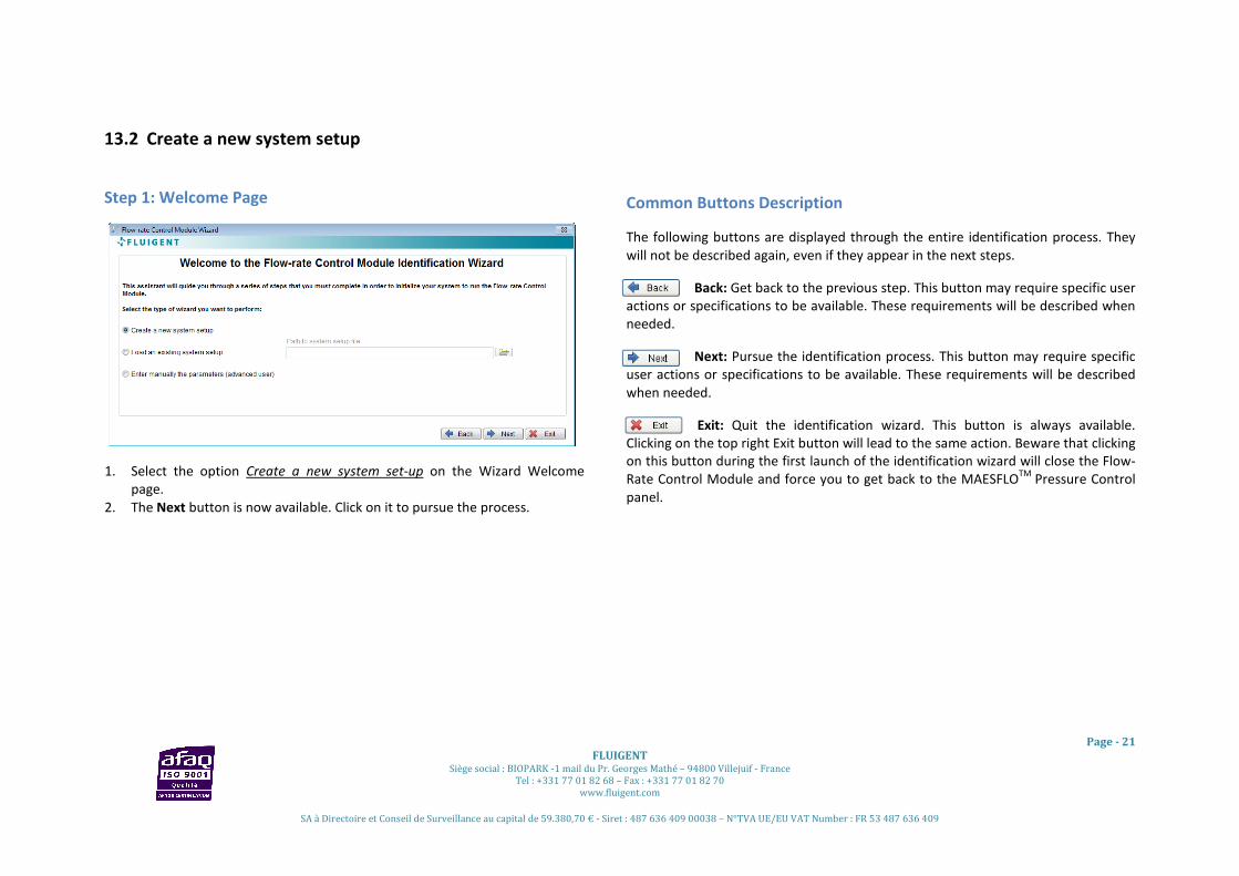
13.2 Create a new system setup
Step 1: Welcome Page
1. Select the option Create a new system set-up on the Wizard Welcome
page.
2. The Next button is now available. Click on it to pursue the process.
Common Buttons Description
The following buttons are displayed through the entire identification process. They
will not be described again, even if they appear in the next steps.
Back: Get back to the previous step. This button may require specific user
actions or specifications to be available. These requirements will be described when
needed.
Next: Pursue the identification process. This button may require specific
user actions or specifications to be available. These requirements will be described
when needed.
Exit: Quit the identification wizard. This button is always available.
Clicking on the top right Exit button will lead to the same action. Beware that clicking
on this button during the first launch of the identification wizard will close the Flow-
Rate Control Module and force you to get back to the MAESFLOTM
Pressure Control
panel.

Page - 22
FLUIGENT Siège social : BIOPARK -1 mail du Pr. Georges Mathé – 94800 Villejuif - France
Tel : +331 77 01 82 68 – Fax : +331 77 01 82 70
www.fluigent.com
SA à Directoire et Conseil de Surveillance au capital de 59.380,70 € - Siret : 487 636 409 00038 – N°TVA UE/EU VAT Number : FR 53 487 636 409
Step 2: Nominal operating configuration
The purpose of this step is to define the nominal operating configuration of
your microsystem.
1. Enter the nominal operating pressure for each pressure channel thanks to
the dedicated Pressure buttons.
2. Monitor on the Flow-rate graph the current flow-rates and check that all
the Flow-rate sensor saturation indicators are green. Then click on the
Nominal Operating button when the flow-rates match your nominal
operating configuration.
3. The Next button is now available. Click on it to pursue the identification
process.
Buttons description
Pressures: These buttons enable to change the applied pressure in
each pressure channel of the MFCSTM
-EZ or MFCSTM
. Input the
requested pressure for the selected channel. By clicking on the up and down arrows,
you can increase or decrease the pressure order with a step of one (1) mbar. The
pressure unit is “mbar”.
Flow-rate sensor saturation: These indicators inform you if any
flow-rate sensor is saturated. A saturated sensor is represented by
a red indicator, otherwise the indicator is green.
Nominal Operating: Click on this button when your microsystem is
in the nominal operating configuration. This button is only available when all the
Flow-rate sensor saturation indicators are green.
Flow-rate Graph: Provide continuous monitoring for all the flow-rate channels.
Frequently Asked Questions (see §17.2)
Why can I not apply the maximal pressure allowed by a pressure channel?
Am I obliged to set a pressure value for all the pressure channels?
Why is the Nominal Operating button disabled?
What is a nominal operating configuration?
How do I stop sensor saturation?

Page - 23
FLUIGENT Siège social : BIOPARK -1 mail du Pr. Georges Mathé – 94800 Villejuif - France
Tel : +331 77 01 82 68 – Fax : +331 77 01 82 70
www.fluigent.com
SA à Directoire et Conseil de Surveillance au capital de 59.380,70 € - Siret : 487 636 409 00038 – N°TVA UE/EU VAT Number : FR 53 487 636 409
Step 3: Channels selection
The purpose of this step is to define the pressure channels that will be used to
control flow-rates. In this step, you will also choose the flow-rate channels you
want to control and define the flow-rate priorities.
1. Select the pressure channels that will be used to control the flow-rates.
FLUIGENT advises you to select every pressure channels.
2. Select the flow-rate channels you want to control and the channel
priority (Low, Medium, or High).
3. Click on the Next button.
Beware that the Next button is only available after selecting at least one (1)
pressure channel and one (1) flow-rate channel with its priority.
Buttons description
Pressure channel: Select the pressure channels used to control
the flow-rates.
Flow-rate channel: Select the flow-rate channels you want to
control and their priority. Three (3) priority levels are available:
High: the Flow-Rate Control Module will always try to match the flow-rate
orders of these channels.
Medium: the Flow-Rate Control Module will try to match the flow-rate orders
of these channels if the orders of the high-priority channels are
matched.
Low: the Flow-Rate Control Module will try to match the flow-rate orders
of these channels if the orders of the medium-priority channels are
matched.
Frequently Asked Questions (see § 17.2)
Will I be allowed to modify the flow-rate priority later?
What does “pressure channels for flow-rate control” mean?
Will I be allowed to modify the selected pressure channels later?
How do I choose the pressure channels?

Page - 24
FLUIGENT Siège social : BIOPARK -1 mail du Pr. Georges Mathé – 94800 Villejuif - France
Tel : +331 77 01 82 68 – Fax : +331 77 01 82 70
www.fluigent.com
SA à Directoire et Conseil de Surveillance au capital de 59.380,70 € - Siret : 487 636 409 00038 – N°TVA UE/EU VAT Number : FR 53 487 636 409
Step 4: Identification
This is an automatic step. During this step, the Flow-Rate Control Module
determines the relations between the selected pressure channels and all the
flow-rate channels. This is achieved by automatic pressure variations on the
pressure channel selected in Step 3: Channels selection.
As the flow-rates will fluctuate during this step, the Flow-rate Graph provides a
flow-rate monitoring of all the channels. The identification quality indicator
provides a continuous overview of the identification quality.
This step lasts a few minutes. The duration increases with the number of
pressure channels selected in the previous step. You can stop the process by
clicking on the Exit button. In this case, the identification process is not
completed and cannot be applied in the Flow-Rate Control Module.
Buttons description
Identification quality: This indicator provides an estimation
of the identification quality while the system is computing the
model. Three (3) colors, linked to quality levels, may be
displayed.
Green (High): The Flow-Rate Control Module will control your microsystem
with optimal performances.
Orange (Medium): You can use the Flow-Rate Control Module. The
performances will be sufficient enough to control your
microsystem.
Black (Low): FLUIGENT advises you to restart the identification process.
User message: This indicator provides information about the process and
potential error messages.
Frequently Asked Questions (see § 17.2)
How do I improve the identification quality?
Why does the automatic identification stop with an error message?
How can I do to avoid backflows in my microsystem(s)?
Does the identification step consume liquids?

Page - 25
FLUIGENT Siège social : BIOPARK -1 mail du Pr. Georges Mathé – 94800 Villejuif - France
Tel : +331 77 01 82 68 – Fax : +331 77 01 82 70
www.fluigent.com
SA à Directoire et Conseil de Surveillance au capital de 59.380,70 € - Siret : 487 636 409 00038 – N°TVA UE/EU VAT Number : FR 53 487 636 409
Step 5: Save and apply settings
This is the final step of the identification process. To complete the identification
process and start using the flow-rate control, please:
1. Select Save new settings if you want to save the identification result on
a dedicated file.
2. Select Apply new settings if you want to use the Flow-Rate Control
Module with the new identification result.
3. Click on the Go button to start the flow-rate control.
A quick summary is available containing:
• The identification quality.
• The serial number of the MFCSTM
-EZ or MFCSTM
and FLOWELL used.
• The name of pressure and flow-rate channels.
• The flow-rate channel priorities.
If you do not want to save or apply the identification result just created, please:
• Click on New Identification button to get back to the Welcome page
without saving or applying the current result.
Buttons description
Save: Save the identification result on a dedicated file.
Apply: Apply the identification result to the Flow-Rate Control
Module. This button is available after selecting the Save button.
Go: Finish the identification process and validate your choices.
New Identification: Get back to the Welcome Page without saving or
applying the identification result. Your previous Flow-Rate Control
Module configuration (identification result, parameter) are
maintained.
Identification name: Rename the identification result as wanted. It
will help you to quickly recognize the identification files.
Notes: Input some personal notes regarding this identification.

Page - 26
FLUIGENT Siège social : BIOPARK -1 mail du Pr. Georges Mathé – 94800 Villejuif - France
Tel : +331 77 01 82 68 – Fax : +331 77 01 82 70
www.fluigent.com
SA à Directoire et Conseil de Surveillance au capital de 59.380,70 € - Siret : 487 636 409 00038 – N°TVA UE/EU VAT Number : FR 53 487 636 409
13.3 Load an existing system setup
Step 1: Welcome Page
1. Select the option Load an existing system setup on the Wizard Welcome
page.
2. The Path button is now available. Click on it to select the identification file
you want to load.
3. Click on the Next button to pursue.
Common Buttons Description
The following buttons are displayed through the entire identification process. They
will not be described again, even if they appear in the next steps.
Back: Get back to the previous step. This button may require specific user
actions or specifications to be available. These requirements will be described when
needed.
Next: Pursue the identification process. This button may require specific
user actions or specifications to be available. These requirements will be described
when needed.
Exit: Quit the identification wizard. This button is always available.
Clicking on the top right Exit button will lead to the same action. Beware that clicking
on this button during the first launch of the identification wizard will close the Flow-
Rate Control Module and force you to get back to the MAESFLOTM
Pressure Control
panel.
Button Description
File Path: Select the identification file that you want to load. The default
path is C:\Fluigent\Maesflo\Identification. All identification files are saved
in this folder by the software.
Frequently Asked Questions (see § 17.3)
I do not recognize the identification file names.

Page - 27
FLUIGENT Siège social : BIOPARK -1 mail du Pr. Georges Mathé – 94800 Villejuif - France
Tel : +331 77 01 82 68 – Fax : +331 77 01 82 70
www.fluigent.com
SA à Directoire et Conseil de Surveillance au capital de 59.380,70 € - Siret : 487 636 409 00038 – N°TVA UE/EU VAT Number : FR 53 487 636 409
Step 2: Loading file report
This step analyzes the identification file and informs you whether you can apply
it with the current FLUIGENT connected devices. A quick summary of the
identification file is available, containing:
• The name you chose for the identification.
• The note you wrote.
• The identification quality.
• The serial number of MFCSTM
-EZ or MFCSTM
and FLOWEL used.
• The name of pressure and flow-rate channels.
• The flow-rate channel priorities.
If the selected identification matches the FLUIGENT connected devices, please
click on the Go Button to apply the identification result and start using the flow-
control.
If the selected identification does not match the FLUIGENT connected devices,
please restart the process. The software provides you with more details about
the reasons of the failure (Details section).
Frequently Asked Questions (see § 17.3)
Why can I not load a previous identification file?
I can load a previous identification file but the flow-rate control performances are
deteriorated.

Page - 28
FLUIGENT Siège social : BIOPARK -1 mail du Pr. Georges Mathé – 94800 Villejuif - France
Tel : +331 77 01 82 68 – Fax : +331 77 01 82 70
www.fluigent.com
SA à Directoire et Conseil de Surveillance au capital de 59.380,70 € - Siret : 487 636 409 00038 – N°TVA UE/EU VAT Number : FR 53 487 636 409
13.4 Enter manually the parameters (Advanced user)
Step 1: Welcome page
1. Select the option Enter manually the parameters (advanced user) on the
Wizard Welcome page.
2. The Next button is now available. Click on it to pursue.
Common Buttons Description
The following buttons are displayed through the entire identification process.
They will not be described again, even if they appear in the next steps.
Back: Get back to the previous step. This button may require specific
user actions or specifications to be available. These requirements will be
described when needed.
Next: Pursue the identification process. This button may require
specific user actions or specifications to be available. These requirements will be
described when needed.
Exit: Quit the identification wizard. This button is always available.
Clicking on the top right Exit button will lead to the same action. Beware that
clicking on this button during the first launch of the identification wizard will
close the Flow-Rate Control Module and force you to get back to the MAESFLOTM
Pressure Control panel.

Page - 29
FLUIGENT Siège social : BIOPARK -1 mail du Pr. Georges Mathé – 94800 Villejuif - France
Tel : +331 77 01 82 68 – Fax : +331 77 01 82 70
www.fluigent.com
SA à Directoire et Conseil de Surveillance au capital de 59.380,70 € - Siret : 487 636 409 00038 – N°TVA UE/EU VAT Number : FR 53 487 636 409
Step 2: Identification for advanced user (Channels selection)
The purpose of this step is to define the pressure channels that will be used to
control flow-rates. In this step, you will also choose the flow-rate channels you
want to control and define the flow-rate priorities. All the actions and buttons
described here are available on the Channel Selection tab.
1. Select the pressure channels that will be used to control flow-rates.
2. Select the flow-rate channels you want to control and the priority of each
flow-rate channel (Low, Medium or High).
Beware that the Next button is only available after you selected at least one (1)
pressure channel and one (1) flow-rate channel with its priority.
Buttons description
Pressure channel: Select the pressure channels used to control
the flow-rates.
Flow-rate channel: Select the flow-rate channels you want to
control and their priority. Three (3) priority levels are available:
High: the Flow-rate Control Module will always try to match the flow-rate
orders of these channels.
Medium: the Flow-rate Control Module will try to match the flow-rate orders
of these channels if the orders of the high-priority channels are
matched.
Low: the Flow-rate Control Module will try to match the flow-rate orders
of these channels if the orders of the medium-priority channels are
matched.
Frequently Asked Questions (see § 17.4)
Will I be allowed to modify the flow-rate priority later?
What does “pressure channels for flow-rate control” mean?
Will I be allowed to modify the selected pressure channels later?

Page - 30
FLUIGENT Siège social : BIOPARK -1 mail du Pr. Georges Mathé – 94800 Villejuif - France
Tel : +331 77 01 82 68 – Fax : +331 77 01 82 70
www.fluigent.com
SA à Directoire et Conseil de Surveillance au capital de 59.380,70 € - Siret : 487 636 409 00038 – N°TVA UE/EU VAT Number : FR 53 487 636 409
Step 2: Identification for advanced user (Identification parameters)
The purpose of this step is to define all the identification parameters before
starting the identification run. All the buttons and actions described here are
available on the Identification Parameters tab.
• With the P max button, enter the maximal pressure that will be applied
during the identification step for the selected channel.
• With the P min button, enter the minimal pressure that will be applied
during the identification step for the selected channel.
• With the Response time slider, select the pressure variation speed that
will be applied during the identification step.
• Click on the Identification Go/Pause button to start the identification run.
This button is only available after you selected at least one (1) pressure
channel and one (1) flow-rate channel with its priority.
FLUIGENT advises you to select ΔP (Pmax-Pmin) greater than 20% of the maximal
pressure available.
Buttons description
Pmax: Select the maximal pressure that will be applied during the
identification run for the selected channel. The pressure order unit is
mbar. The Pmax values cannot be inferior to the Pmin values of the
same channel. This button is an array: the first row corresponds to the first
pressure channel, etc..
Pmin: Select the minimal pressure that will be applied during the
identification run for the selected channel. The pressure order unit is
mbar. The Pmin values cannot be superior to the Pmax values of the
same channel. This button is an array: the first row corresponds to the first
pressure channel, etc..
Flow-rate sensor saturation: These indicators inform you if any flow-
rate sensor is saturated. A saturated sensor is represented by a red
indicator, otherwise the indicator is green.
Pressure response time: This slider modifies the speed of the
pressure variation. It leads to reduce the flow-rate overshoots due
to air bubbles. The modification impacts all the pressure channels.
Identification Go/Pause: By clicking on it you can start or stop the
identification run. You can pause the identification for as long as you you want
and then restart it.
Frequently Asked Questions (see § 17.4)
How do I choose the Pmax and Pmin values?
When do I stop the identification?

Page - 31
FLUIGENT Siège social : BIOPARK -1 mail du Pr. Georges Mathé – 94800 Villejuif - France
Tel : +331 77 01 82 68 – Fax : +331 77 01 82 70
www.fluigent.com
SA à Directoire et Conseil de Surveillance au capital de 59.380,70 € - Siret : 487 636 409 00038 – N°TVA UE/EU VAT Number : FR 53 487 636 409
Step 2: Identification for advanced user (Identification run)
During this step, the Flow-Rate Control Module will apply pressure orders
simultaneously on all the pressure channels you have selected before. During
the run, please:
• Check the Flow-rate sensor saturation indicators: they have to stay
green.
• All the parameters described before on the Channel Selection and
Identification Parameters pages are available. Do not hesitate to
modify them to keep the Flow-rate sensor saturation indicators green.
• Check the Identification quality indication (high, medium, low) to have
a feedback on the identification run.
• Click on the Next button when the identification quality is good enough
for you (after 2 minutes). This will end the identification run. FLUIGENT
advises you to obtain at least a Medium identification quality.
The Flow-rate graph provides you with continuous monitoring of the flow-rates.
Please be aware that you can end the run at any moment by clicking on the
Next button. You also can stop and restart the identification run at any time by
clicking on the Identification Go/Wait button.
Button description
Identification quality: This indicator provides an estimation
of the identification quality at the end of the identification
run (after 2 minutes). Three (3) colors, linked to quality levels,
may be displayed.
Green (High): The Flow-Rate Control Module will control your microsystem
with optimal performances.
Orange (Medium): You can use the Flow-Rate Control Module. The
performances will be good enough to control your
microsystem.
Black (Low): FLUIGENT advises you to restart the identification process.
Frequently Asked Questions (see § 17.4)
Why does the Flow-rate sensor saturation need to stay green?
How do I avoid flow sensor saturation?
Does the identification step consume liquids?

Page - 32
FLUIGENT Siège social : BIOPARK -1 mail du Pr. Georges Mathé – 94800 Villejuif - France
Tel : +331 77 01 82 68 – Fax : +331 77 01 82 70
www.fluigent.com
SA à Directoire et Conseil de Surveillance au capital de 59.380,70 € - Siret : 487 636 409 00038 – N°TVA UE/EU VAT Number : FR 53 487 636 409
Step 3: Save and apply settings
This is the final step of the identification process. To complete the identification
process and start using the flow-rate control, please:
1. Select Save new settings if you want to save the identification result on
a dedicated file.
2. Select Apply new settings if you want to use the Flow-Rate Control
Module with the new identification result.
3. Click on the GO button to start the flow-rate control.
A quick summary is available containing:
• The identification quality.
• The serial number of the MFCSTM
-EZ or MFCSTM
and FLOWELL used.
• The name of pressure and flow-rate channels.
• The flow-rate channel priorities.
If you do not want to save or apply the identification result just created, please:
• Click on New Identification button to get back to the Welcome page
without saving or applying the current result.
Buttons description
Save: Save the identification result on a dedicated file.
Apply: Apply the identification result to the Flow-Rate Control
Module. This button is available after selecting the Save button.
Go: Finish the identification process and validate your choices.
New Identification: Get back to the Welcome Page without saving or
applying the identification result. Your previous Flow-Rate Control
Module configuration (identification result, parameter) are
maintained.
Identification name: Rename the identification result as wanted. It
will help you to quickly recognize the identification files.
Notes: Input some personal notes regarding this identification.

Page - 33
FLUIGENT Siège social : BIOPARK -1 mail du Pr. Georges Mathé – 94800 Villejuif - France
Tel : +331 77 01 82 68 – Fax : +331 77 01 82 70
www.fluigent.com
SA à Directoire et Conseil de Surveillance au capital de 59.380,70 € - Siret : 487 636 409 00038 – N°TVA UE/EU VAT Number : FR 53 487 636 409
14. MAESFLOTM
Flow-Rate Control panel
14.1 Overview The following panel provides you with all the flow-rate control features. Thanks to it, you will be able to control
the flows through your microsystem by flow-rate orders.
In this section, we will start by describing the buttons dedicated to the flow-rate control. We will finish this
section by describing the functionalities shared by the MAESFLOTM
Pressure Control panel and the MAESFLOTM
Flow-Rate Control panel. So you will be totally aware of all the flow control solutions for your microsystem.
14.2 Panel description
The Flow-Rate Control panel provides the following
functionalities:
• Apply flow-rate orders.
• Limit the maximum and minimum flow-rates.
• Flow-rate channel coupling.
• Inform about the achievability of the flow-rate
orders.
• Modify the flow-rate unit.
• Modify the flow-rate channel name.
• Modify the flow-rate channel priority.
• Get to the Parameters window.
• Get to the Pressure Control panel.
• Record data.
• Create flow-rate order configurations.
• Apply flow-rate order configurations.
• Set all pressures to zero (emergency stop).
• Stop or run the flow-rate-control.
• Get to the identification wizard.
14.3 Buttons description
Flow-rate slider: Modify the flow-rate order on the selected channel quickly by sliding the pointer.
The unit is selected by the Unit button. The slider range is the range of the flow-rate sensor
currently connected.
Flow-rate control: Input the requested flow-rate order for the selected channel. By clicking on the
up and down arrows, you can increase or decrease the order with a step of one (1) flow-rate unit.
The unit is selected by the Unit button.
Flow-rate limit: This button allows you to limit the maximal and minimal flow-rate orders for the
selected channel. You can use it as a safety button. For example, enter a value of “15” will limit the
flow-rate orders between “+15 and -15”. The unit is selected by the Unit button. . By clicking on
the up and down arrows, you can increase or decrease the limit with a step of one (1) flow-rate unit.

Page - 34
FLUIGENT Siège social : BIOPARK -1 mail du Pr. Georges Mathé – 94800 Villejuif - France
Tel : +331 77 01 82 68 – Fax : +331 77 01 82 70
www.fluigent.com
SA à Directoire et Conseil de Surveillance au capital de 59.380,70 € - Siret : 487 636 409 00038 – N°TVA UE/EU VAT Number : FR 53 487 636 409
Unit: Modify the displayed unit of all channels for the Flow-Rate Control panel. The units available
are: µL/min, µL/h, nL/min, nL/h. Be aware that the Flow-rate Panel is not impacted by your choice
and always displays the flow-rate measurements in µL/min.
Coupling channel: Easily link the flow-rate channel settings between several channels by selecting
the appropriate coupling label in the drop down menu. Two or more channels are coupled when
the same coupling label is displayed for the selected channels.
When channels are coupled with “C+” or “D+” label, increasing (decreasing) the flow-rate order of one (1)
channel will increase (decrease) the flow-rate order of the other(s) channel(s) of the same amount.
When channels are coupled with “C-” or “D-” label, increasing (decreasing) the flow-rate order of one (1)
channel will decrease (increase) the flow-rate order of the other(s) channel(s) of the same amount.
Flow-rate achievability: This indicator informs you continuously on the achievability of the flow-
rate order for the selected channel. The green color means that the flow-rate order will be reached
by the Flow-Rate Control Solution. The red color means that the flow-rate order cannot be reached
by the Flow-Rate Control Solution. In this case, the Flow-Rate Control Module will reach the closest flow-rate
achievable from your order. See more details at § 12.2.
Switch Panel: Click on it for a direct access to the Pressure Control panel.
Parameters: Click on it for a direct access to the Parameters panel.
Record: Click on it to record the pressure and flow-rate measurements of all the pressure and
flow-rate channels. The pressure orders are also recorded. Click on it again will stop the record.
The record period is shown on the right side of this button. This button provides the same features than the
Record button in the Pressure Control panel. See more details at §11.4.
Config Q: Click on it to save the current flow-rate orders of all the flow-rate channels. The
configuration is saved on a dedicated file (default path: C:\Fluigent\Maesflo\ConfigQ). The
saved configuration will be available in the Apply Config Q button. See more details at § 15.1.
Apply Config Q: This button provides a drop-down menu containing all the flow-rate
configurations previously saved in the configuration folder and selected in the Parameters/Flow-Rate panel
(see at §15.1). By selecting the desired configuration, the saved flow-rate orders will instantaneously and
simultaneously be applied to all the flow-rate channels. So you can use this feature to quickly switch from one
configuration to another corresponding, for example, to different working modes. Please note that shortcut is
not available for flow-rate configurations (only for pressure configurations).
Zero pressure: Click on it to instantaneously apply a zero pressure order on all the pressure
channels. You can use this button as an emergency stop. By clicking on it, the flow-rate control

Page - 35
FLUIGENT Siège social : BIOPARK -1 mail du Pr. Georges Mathé – 94800 Villejuif - France
Tel : +331 77 01 82 68 – Fax : +331 77 01 82 70
www.fluigent.com
SA à Directoire et Conseil de Surveillance au capital de 59.380,70 € - Siret : 487 636 409 00038 – N°TVA UE/EU VAT Number : FR 53 487 636 409
is stopped: your flow-rate orders are not taken into account by the software. Click on the Pause button to
restart the flow-rate control.
Pause: Click on it to stop the flow-rate control. When the flow-rate control is stopped, the
button background color is gray, otherwise it is blue. When the flow-rate control is stopped, all
the flow-rate order changes are not taken into account until you click again on the button. So
you can modify the flow-rate orders of each channel, corresponding to another working mode of your
microsystem for example, and apply them simultaneously by clicking again on the button. When the flow-rate
control is stopped, all the pressure channels are available even those used by the Flow-Rate Control Module.
See more details about the Pressure Control and Flow-Rate Control Module interactions at § 16.
Identification: Click on it for a direct access to the identification wizard. See more details at §13.
14.4 Right click controls
Right-clicking on any Flow-rate slider displays two
hidden controls:
• Modify flow-rate channel names.
• Modify selected flow-rate channel priority.
Change flow-rate channel names
1. Click on Change Names in the popping menu (here opposite window
appears).
2. Change the flow-rate channel names as wanted.
3. Click on the OK button to apply your modifications.
4. Click on the Cancel button to get back to the previous names.
Your modifications will be taken into account in all the MAESFLOTM
software.
Change priority:
1. Click on Change Priority in the popping menu.
2. Select the priority for the related flow-rate channel. Three (3) priority levels are available:
High: the Flow-Rate Control Module will always try to match the flow-rate orders of these
channels.
Medium: the Flow-Rate Control Module will try to match the flow-rate orders of these channels if
the orders of the high-priority channels are matched.
Low: the Flow-Rate Control Module will try to match the flow-rate orders of these channels if
the orders of the medium-priority channels are matched.

Page - 36
FLUIGENT Siège social : BIOPARK -1 mail du Pr. Georges Mathé – 94800 Villejuif - France
Tel : +331 77 01 82 68 – Fax : +331 77 01 82 70
www.fluigent.com
SA à Directoire et Conseil de Surveillance au capital de 59.380,70 € - Siret : 487 636 409 00038 – N°TVA UE/EU VAT Number : FR 53 487 636 409
15. MAESFLOTM
parameters dialog for Flow-Rate Control Module
The Parameters panel enables to check, create or modify the following parameters:
• Flow-rate configurations.
• Flow-rate channel priority.
• Pressure channel used for the MAESFLOTM
Flow-Rate Control Module.
• The pressure response time.
• The identification files (saved results of a previous identification process).
Click on the Parameters button from the Flow-Rate Control panel or from the Pressure Control panel to display
the Parameters panel.
15.1 Flow-rate configurations
Select the Configurations/Flow-rate category to
access the panel opposite.
The Configuration file list displays the saved
configurations in the folder specified in the
Configuration folder path. The default folder path
is C:\Fluigent\Maesflo\ConfigQ.
Select the desired configurations in the
Configuration folder list to make them available in
the Apply Config Q button (see at §14.3).
Apply your choices by clicking on the OK button.
Clicking on the Cancel button will cancel all the
changes you have made.
15.2 Flow-Rate Control Module
Select the Flow-Rate Control Module category to
access the panel opposite.
This panel provides an overview on the main
parameters used by the Flow-Rate Control Module.
It enables to check or modify the following
parameters:
• Pressure channels used by the Flow-Rate
Control Module.
• Flow-rate channels controlled.
• Priority of the flow-rate channels.
• Pressure response time.
Apply your choices by clicking on the OK button.
Clicking on the Cancel button will cancel all the
changes you have made.

Page - 37
FLUIGENT Siège social : BIOPARK -1 mail du Pr. Georges Mathé – 94800 Villejuif - France
Tel : +331 77 01 82 68 – Fax : +331 77 01 82 70
www.fluigent.com
SA à Directoire et Conseil de Surveillance au capital de 59.380,70 € - Siret : 487 636 409 00038 – N°TVA UE/EU VAT Number : FR 53 487 636 409
Pressure Channels used by Flow-Rate Control Module
This button displays the following information for all the pressure channels:
• Pressure channels used during the identification process.
• Pressure channels currently used by the Flow-Rate Control Module to control the
flow-rate channels.
• Pressure channels used during the identification process but currently used for
pressure control.
• Pressure channels dedicated to the pressure control.
The pressure channels used during the identification process are displayed as “not grayed”. For these pressure
channels you can decide to:
• Use them for flow-rate control. In this case, the pressure of these channels will be controlled and
automatically adjusted by the Flow-Rate Control Module to reach the flow-rate orders. These pressure
channels are displayed as “selected”.
• Use them for pressure control. In this case, you can modify the pressure orders by yourself in the
Pressure Control panel. These pressure channels are displayed as “unselected”. These pressure channels
will stay available for being used for flow-rate control.
The pressure channels dedicated to pressure control are those not used during the identification process. They
appear “grayed” (see the channel 2 in the example above). You cannot use them for flow-rate control.
Please see more details at §12.1 .
Frequently Asked Questions
Why are some pressure channels grayed in the Parameters/Flow-Rate Control Module panel?
How do I choose the pressure channels used for the flow-rate control?
Flow-rate channel and priority
This button displays the current controlled flow-rate channels and their priority. The
number of channels depends of the number of flow-rate sensors currently connected.
To obtain a monitored flow-rate channel, unselect the related Channel button. Its
priority is automatically changed to None. All its related controls and indicators on the
Flow-Rate Control Module panel will be disabled and grayed.
To add a new controlled flow-rate channel, select the related Channel button. Then choose which priority you
want to apply for this channel. Three (3) priority levels are available:
High: the Flow-Rate Control Module will always try to match the flow-rate orders of these channels.
Medium: the Flow-Rate Control Module will try to match the flow-rate orders of these channels if the orders
of the high priority channel are matched.
Low: the Flow-Rate Control Module will try to match the flow-rate orders of these channels if the orders
of the medium priority channel are matched.
(None: the channel is only monitored)
To modify the priority of a controlled flow-rate channel, please just change the priority level on the related
Priority button.

Page - 38
FLUIGENT Siège social : BIOPARK -1 mail du Pr. Georges Mathé – 94800 Villejuif - France
Tel : +331 77 01 82 68 – Fax : +331 77 01 82 70
www.fluigent.com
SA à Directoire et Conseil de Surveillance au capital de 59.380,70 € - Siret : 487 636 409 00038 – N°TVA UE/EU VAT Number : FR 53 487 636 409
Frequently Asked Questions
Why should I change the flow-rate channel priority?
Can I use flow-rate channels for flow-rate control even if I have not selected them during the identification
process?
Pressure response time
This button displays the current pressure response. By default, this value is set to Stable.
Increasing the response time will lead to more stable flow-rates while the delay to reach a
new flow-rate order will increase. Increasing the response time also limits the flow-rate
overshoots which may appear in a micro system with air bubbles. The changes are applied for
all the pressure channels.
Four (4) labels, corresponding to different pressure response time are available:
• Fastest: the pressure order is reached thanks to the highest MFCSTM
or MFCSTM
-EZ response time.
• Fast: the pressure order is reached in approximately 1 second.
• Stable: the pressure order is reached in approximately 3 seconds.
• Stablest: the pressure order is reached in approximately 5 seconds.
Frequently Asked Questions
Why should I change the pressure response time?
Why is the pressure variation so slow?

Page - 39
FLUIGENT Siège social : BIOPARK -1 mail du Pr. Georges Mathé – 94800 Villejuif - France
Tel : +331 77 01 82 68 – Fax : +331 77 01 82 70
www.fluigent.com
SA à Directoire et Conseil de Surveillance au capital de 59.380,70 € - Siret : 487 636 409 00038 – N°TVA UE/EU VAT Number : FR 53 487 636 409
15.3 Identification File Viewer
This parameters panel displays all the identification
file features. It will help you to choose the
appropriate file for loading.
To access this parameters panel, please:
1. Get to the Parameters/Flow-rate Control
Module category.
2. Click on the Edit Regulation System Setup File
link (on the bottom right of the panel).
The next window is now available. The File List displays all the identification files saved in the
C:\Fluigent\Maesflo\Identification folder. If you saved an identification file in another folder, it will not be
displayed in this list.
Select the identification file you want to check for loading on the File List. For each identification file, the
following data are given:
• Identification name: the name you chose for the identification file during the Save and Apply step of the
identification wizard.
• Notes: the notes you wrote for the identification file during the Save and Apply step of the identification
wizard.
• Date and time: Date and time of the identification file creation.
• Path: path of the selected identification file.
• Identification quality: FLUIGENT advises you to use identification with at least a Medium quality.
• Serial number of the MFCSTM
-EZ or MFCSTM
used during the identification process (up to 4 MFCSTM
-EZ,
or 2 MFCSTM
, or 1 MFCSTM
and 1 MFCSTM
-EZ).
• Serial number of the FLOWELL used during the Identification process (up to 2 FLOWELL).
• Channels data: number and name of pressure channel(s) and flow-rate channel(s) used during the
identification process. The flow-rate channel priority is also displayed.
• Details: details about the reason why you cannot load the identification file selected (if happening). The
main reasons are:
1. Different number of pressure channels and /or flow-rate channels.
2. Different ranges of the pressure channels and/or flow-rate channels.

Page - 40
FLUIGENT Siège social : BIOPARK -1 mail du Pr. Georges Mathé – 94800 Villejuif - France
Tel : +331 77 01 82 68 – Fax : +331 77 01 82 70
www.fluigent.com
SA à Directoire et Conseil de Surveillance au capital de 59.380,70 € - Siret : 487 636 409 00038 – N°TVA UE/EU VAT Number : FR 53 487 636 409
16. Flow-Rate Control Module and Pressure Control interactions
The MAESFLOTM
Pressure Control provides a direct
control of the MFCSTM
-EZ or MFCSTM
pressure
channels. The MAESFLOTM
Flow-Rate Control
Module provides flow-rate control by
automatically adjusting pressure orders. This
principle leads to physical and software
interactions that will be described below.
Pressure orders
The pressure channels used for the flow-rate control are grayed in the Pressure Control panel when the flow-
rate control is running. So you cannot change the pressure order for these channels.
By clicking on the Pause button of the Flow-Rate Control panel, the flow-rate control is temporarily stopped. All
pressure channels are now available for modification: you can change the pressure orders of all channels.
Pressure limit
The pressure limits inputted in the Pressure Control panel are taken into account by the Flow-Rate Control
Module. It will adapt the pressures of the selected channels to reach the flow-rate orders in the range defined
by the pressure limit.
By clicking on the Pause button of the Flow-Rate Control panel, the flow-rate control is temporarily stopped. All
pressure channels are now available for modification: you can change the pressure limit of all channels.
Configurations
You can use the saved pressure configurations while the Flow-Rate Control Module is running. The
configurations will not be applied to the pressure channels controlled by the Flow-Rate Control Module. The
Flow-Rate Control Module will still control these channels as usual.
Pressure response time
The pressure response time can be modified in the Parameters/Flow-Rate Control Module panel. The value
selected will be applied to all the pressure channels when the flow-rate control is running.
Zero Pressure, Parameters and Record
These three (3) buttons are displayed on the Pressure Control panel and the Flow-Rate Control panel. They lead
to the exact same features.

Page - 41
FLUIGENT Siège social : BIOPARK -1 mail du Pr. Georges Mathé – 94800 Villejuif - France
Tel : +331 77 01 82 68 – Fax : +331 77 01 82 70
www.fluigent.com
SA à Directoire et Conseil de Surveillance au capital de 59.380,70 € - Siret : 487 636 409 00038 – N°TVA UE/EU VAT Number : FR 53 487 636 409
17. Frequently asked questions
17.1 How to start All the FLUIGENT devices needed are connected to my computer but the Flow-Rate Control Module option is
still disabled.
Please make sure that the FLOWELL are selected by the MAESFLOTM
software. To be sure that a FLOWELL is
selected, try to display the Flow-rate Graph window or the Flow-rate Panel by clicking on the Display menu. If
these options are disabled, you have to select a FLOWELL. To select a FLOWELL, please follow the instruction at
§11.2.
After checking the FLOWELL connection, if the Flow-Rate Control Module option remains disable, please check
your dongle key connection and restart the MAESFLOTM
.
17.2 Create a new system setup Why can I not apply the maximal pressure allowed by a pressure channel?
The identification wizard takes into account the pressure limit you specified for each pressure channel in the
MAESFLOTM
(see at §16). Please check or modify these limits.
Am I obliged to set a pressure value for all the pressure channels?
No, please only modify the pressure channels you need to match the nominal operating configuration of your
micro system. If the required configuration is “zero pressure” for all pressure channels, the software will also
be able to deal with it.
Why is the Nominal Operating button disable?
This button is only available when all the Flow-rate sensor saturation indicators are green.
What is a nominal operating configuration?
A nominal operating configuration is a flow-rate and/or pressure configuration usually used in your
microsystem.
How do I stop sensor saturation?
Modify the pressure values of the pressure channels. Usually, by decreasing the pressure value you will be able
to stop a flow-rate sensor saturation. Modify first the pressure channels which have a major impact on the
flow-rate channel currently saturated.
Will I be allowed to modify the flow-rate priority later?
Yes you will. This step only configures the MAESFLOTM
with your current choices. After completing the wizard,
you will be able to change the priorities.
What does “pressure channels for flow-rate control” mean?
It means that the selected pressure channels will be automatically adjusted by the software to provide the
requested flow-rates. You will not be able to modify the pressure of these channels yourself. You can control all
the other pressure channels (not selected in this step) with the Pressure Control panel.
Will I be allowed to modify the selected pressure channels later?
Yes but you will not be allowed to add new pressure channels for flow-rate control. A new identification
process is required in this case.
How do I choose the pressure channels?
The selected pressures should be connected to the flow-rate channels regarding the microfluidic design of your
setup. It means that a pressure modification leads to a flow-rate modification. If you cannot define these
relations, please select all the pressure channels available. The Flow-Rate Control Module is able to figure out
all the relations between pressure and flow-rate channels.

Page - 42
FLUIGENT Siège social : BIOPARK -1 mail du Pr. Georges Mathé – 94800 Villejuif - France
Tel : +331 77 01 82 68 – Fax : +331 77 01 82 70
www.fluigent.com
SA à Directoire et Conseil de Surveillance au capital de 59.380,70 € - Siret : 487 636 409 00038 – N°TVA UE/EU VAT Number : FR 53 487 636 409
How do I improve the identification quality?
You can improve the quality by avoiding transitory phenomena in your system during the identification
(bubble, clogging, liquid leaks, valve actuating, etc...).
Why does the automatic identification stop with an error message?
The software stops the identification if too many flow-rate sensor saturations occurred.
To limit saturations, try to avoid air bubbles in your microsystem. Bubbles in a micro system may lead to flow-
rate overshoots when a new pressure order is applied. The bigger the bubble is, the higher the flow-rate
overshoot may be.
Please also be sure that the flow sensor ranges and the pressure channel ranges are suitable for your
microsystem. If a flow sensor saturates when you applied less than 20% of the maximum pressure available,
the ranges are not suitable for your microsystem.
How can I avoid backflows in my microsystem(s)?
To be able to guide the flows during the identification step and avoid backflows for example, enter manually
the parameters (advanced user).
Does the identification step consume liquids?
In the identification step, pressures will be applied and consequently liquids will flow inside your microfluidic
system. It means that this identification step will consume some liquids. If you do not want to use your samples
(delicate and/or costly) you can make the identification with model samples (with characteristics close to your
real sample). After the completion of the identification step, you fill your reservoirs with your real sample, load
the identification file and then perform your experiment.
17.3 Load an existing system setup I do not recognize the identification file names.
Please be aware that the identification file name differs from the identification name you inputted during the
Save and apply setting step. The identification file name is indeed automatically created by the MAESFLOTM
.
Please use the identification file viewer for concordance between identification file name and the identification
name you wrote (see at §15.3).
Why can I not a previous identification file?
The software cannot apply a previous identification if the FLUIGENT devices connected do not exactly match
those used during the creation of the identification file. The Details section gives you more information about
the reasons why a file has not been loaded.
The following parameters must be the same:
• Number of MFCSTM
-EZ (or MFCSTM
) and FLOWELL.
• Number and range of pressure channels.
• Number and range of flow-rate sensors.
I can load a previous identification file but the flow-rate control performances are deteriorated.
The Flow-Rate Control Module guaranties you that the FLUIGENT connected devices match the previous used
during the creation of the identification file. You must be aware that the performances depend on the
microsystem and how you set it up.
For example, if the microsystem currently used is different than the system used to create the identification file
(other chip design), the regulation performances may be deteriorated.
If you use the same microsystem but connect the pressure channels (or flow-rate channels) a different way, the
performances may not be good enough. It means that the pressure and flow-rate channels must be connected
to the same input/output.

Page - 43
FLUIGENT Siège social : BIOPARK -1 mail du Pr. Georges Mathé – 94800 Villejuif - France
Tel : +331 77 01 82 68 – Fax : +331 77 01 82 70
www.fluigent.com
SA à Directoire et Conseil de Surveillance au capital de 59.380,70 € - Siret : 487 636 409 00038 – N°TVA UE/EU VAT Number : FR 53 487 636 409
17.4 Enter manually the parameters (advanced user) Will I be allowed to modify the flow-rate priority later?
Yes you will. This step only configures the MAESFLOTM
with your current choices. After completing the wizard,
you will be able to change the priorities and also control the flow-rate channels with an initial None priority.
What does “pressure channels for flow-rate control” mean?
It means that the selected pressure channels will be automatically adjusted by the software to provide the
wanted flow-rates. You will not be able to modify the pressure of these channels all by yourself. You can
control all the other pressure channels (not selected in this step) with the Pressure Control panel.
Will I be allowed to modify the selected pressure channels later?
Yes but you will not be allowed to add new pressure channels for flow-rate control. A new identification
process is required in this case.
How do I choose the Pmax and Pmin values?
They deeply depend on your micro system but they need to reach two requirements:
1. They must not lead to any flow sensor saturation.
2. They must not be equal. FLUIGENT advises you to select ΔP (Pmax-Pmin) greater than 20% of the
maximal pressure available.
By settling the appropriate pressures (Pmax and Pmin), you will be able to guide your flows as wanted
during the identification step (for example, you will be able to avoid backflows if required).
When do I stop the identification run?
You are allowed to stop the identification when you want. FLUIGENT advises you to go to the next step only if
the identification quality is at least Medium (High would be best). However, the identification run typically lasts
two (2) or three (3) minutes. If the identification quality do not reach a Medium or High quality after 5 minutes,
stop the identification run. Then, try to adpat your system to avoid saturations and/or transitory phenomena.
Why does the Flow-rate sensor saturation need to stay green?
Any flow sensor saturation reduces the identification quality, even on unselected flow-rate channel. By
avoiding flow sensor saturation, you increase the identification quality and decrease the duration needed to
obtain the best performances.
How do I stop a flow-rate sensor saturation?
1. Change the values of the Pmin and Pmax buttons. Generally, reducing the ΔP (Pmax-Pmin) highly
limits the flow sensor saturation. Check which sensor is saturating and modify first the pressure value
of the pressure channels which seem to impact the flow sensor most.
2. Increase the Flow-rate response time slider will help you to limit the transitory saturation due to the
bubbles.
3. Please also be sure that the flow sensor ranges and the pressure channel ranges are suitable for your
microsystem. If a flow sensor saturates when you applied less than 20% of the maximum pressure
available, the ranges are not suitable for your microsystem. Please do not hesitate to contact
FLUIGENT, we will suggest you a dedicated solution for your set-up.
Does the identification step consume liquids?
In the identification step, pressures will be applied and consequently liquids will flow inside your microfluidic
system. It means that this identification step will consume some liquids. If you do not want to use your samples
(delicate and/or costly) you can make the identification with model samples (with characteristics close to your
real sample). After the completion of the identification step, you fill your reservoirs with your real sample, load
the identification file and then perform your experiment.

Page - 44
FLUIGENT Siège social : BIOPARK -1 mail du Pr. Georges Mathé – 94800 Villejuif - France
Tel : +331 77 01 82 68 – Fax : +331 77 01 82 70
www.fluigent.com
SA à Directoire et Conseil de Surveillance au capital de 59.380,70 € - Siret : 487 636 409 00038 – N°TVA UE/EU VAT Number : FR 53 487 636 409
17.5 MAESFLOTM
Parameters dialog for Flow-Rate Control Module Why are some pressure channels grayed in the Parameters/Flow-Rate Control Module panel?
The grayed pressure channels are those only available for the pressure control. These channels have not been
selected during the identification step. The Flow-Rate Control Module is not able to use them for flow-rate
control. If you want to use these channels with the Flow-Rate Control Module, please process a new
identification.
How do I choose the pressure channels used for the flow-rate control?
The selected pressure should be connected to the flow-rate channels regarding the microfluidic design of your
setup. It means that a pressure modification leads to a flow-rate modification. If you cannot define these
relations, please select all the pressure channels available. The Flow-Rate Control Module is able to figure out
all the relation between pressure and flow-rate channels.
Why should I change the flow-rate channel priority?
Adapting the flow-rate priorities may enable you to enlarge the reachable flow-rate range. Please see at §12.3
for further information.
Can I use flow-rate channels for flow-rate control even if I did not select them during the identification
process?
Yes, you can. The Flow-Rate Control Module figures out the relation between selected pressure channels
(during the identification wizard) and all flow-rate channels. The selection of flow-rate channels during the
identification wizard only configures the Flow-Rate Control Module with your initial choice. You are able to
control a flow-rate channel initially configured with a None priority when you want.
Why should I change the pressure response time?
Reducing the pressure response time leads to reduce the flow-rate overshoots that may appear during the
identification process or while the Flow-Rate Control is running. It may be used to increase the identification
quality and/or leads to a more stable flow-rate control. Any pressure response modification is applied to all the
pressure channels even those not used by the Flow-Rate Control Module.
Why is the pressure variation so slow?
Please check the pressure response time value and decrease it to obtain the wanted response time.

Page - 45
FLUIGENT Siège social : BIOPARK -1 mail du Pr. Georges Mathé – 94800 Villejuif - France
Tel : +331 77 01 82 68 – Fax : +331 77 01 82 70
www.fluigent.com
SA à Directoire et Conseil de Surveillance au capital de 59.380,70 € - Siret : 487 636 409 00038 – N°TVA UE/EU VAT Number : FR 53 487 636 409
FLUIGENT
BIOPARK
1 mail du Pr. Georges Mathé
94800 Villejuif
FRANCE
Phone: +331 77 01 82 68
Fax: +331 77 01 82 70
www.fluigent.com
Technical support:
Phone : +331 77 01 82 65
General information: