madhu optical networks
DESCRIPTION
It's good to work and useful for students.TRANSCRIPT
0ptical lay'er
Optical. Networks
Wavelengthchannels
Opticalfiber linl<s
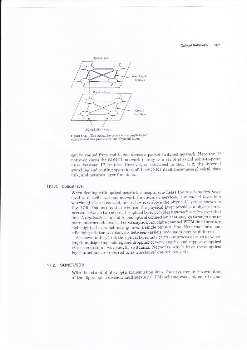
Figure'17.5. The optieal layer is a wavelength-basedconcept and lies just above the physical layer.
can be routed from end to end across a packet-switched network. Here the IPnetwork views the SONET network merely as a set of physical point-to-pointlinks between IP routers. However, as described in Sec. 17.2, t'},e internalswitching and routing operations of the SONET itself encompass physicaL, daLa
link, and network layer functions.
17.1.4. Optical layer
S{:en dealing with optical network concepts, one hea-rs the words optical layer
used to describe various network functions or services. Tlne optical layer is awavelength-based coneept, and it lies just above the phyeical layer, as shown inFig. 17.5. This means that whereas the physical layer provides a physical con-
neciion between trlro nodes, the optical layer provides lightpath seruices over thatlink. A tightpath is an end-to-end optical connection that may go through one ormore interrnediate ncdes. For example, in an eight-channel WDM link there are
eight lightpaths, which may go over a single physical line. Note that for a spe-
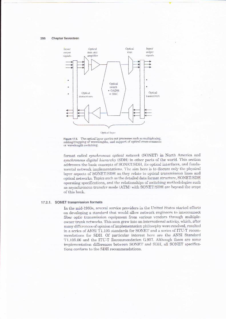
cifrc lightpath the wavelengths between various node pairs may be different.As shown in Fig. 17.6, the optical layer may carry out processes such as wave-
length multiplexing, adding and dropping of wavelengths, and support of optical
cross-connects or wavelength switching. Networks which have these opticallayer functions are referred to as wauelength-routed networks.
'17.2. SONETISDH
With the advent of frber optic transmission lines, the next step in the evolutionof the digitat time division multiplexing (TDM) scheme was a standard signal
SONET/SDH nodes
Chapter Seventeen
Inputloulputsignais
Opticalmux and
arnplifier
Opticalmox
Optical layer
Figure 17.6. T?re optical layer carries aut pracesses such as muitiplexing,addinldropping of wavelengths, and support of optical cross-connectsor wavelength switching.
format calied synchronous aptical network (SONET) in North America andsynchronoas digitet hierarchy {SDH) in other parts of the world. This section
addresses the basic concepts of SONET/SDH, its optical interfaces, and funda-mental network implementations. The aim here is to discuss only the physicallayer aspects of SONET/SDH as they relate to optical transmission lines andoptical networks. Topics such as the detailed data format structure, SONET/SDHoperating specifications, and the relationships of switching methodologies suchas asy'nchronGus transfer rn6de (ATM) with SONET/SDH are beycnd the scope
of this trook.
17,2.1. SONET transmission formats
In the mid-1980s, several service providers in the United States started effortson developing a standard that would allow network engineers to interconnect{iber optic transmission equipment from various vendors through mu}tiple-owner trunk networks. This soon grew into an international activity, which, afterrnany differences of opirrion of implernentation philosophy were resolved, resultedin a series of ANSI T1.105 standards for SONET and a series of ITU-T recom-mendations for SDH. Of particular interest here are the ANSI StandardT1.105.06 and the ITU-T Recommendation G.957. Although there are some
implementation differences between SONET and SDI{, all SONET specifica-tions conform ta the SDH recommendations.
Optical l,Ietworks
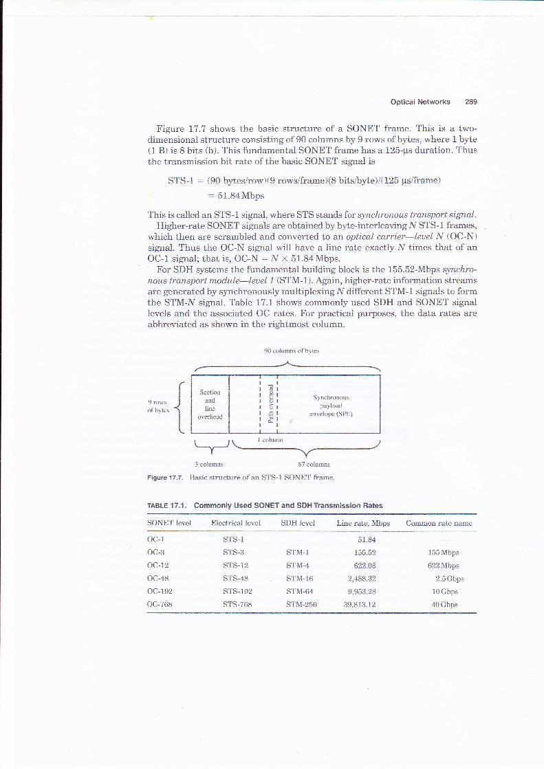
Figure 17"7 shows the basic structure of a SONET frame. This is a two-dimensional structure consisting of 90 columns by I rows of bytes, where 1 byte(1 B) is 8 bits (b). This fundamental SONET frame has a 125-ps duration. Thusthe transmission bit rate of the basic SONET signal is
STS-1 : (90 bytes/rowX9 rowsframe)(8 bits&yie)l{125 irs/frame): 51.84Mbps
This is called an STS-1 signal, where STS stands for synchronous transpor-t signal.Higher-rate SONET signals are obtained by byte-interleavingN STS-1 frames,
which then are scrambled and converted to an optical cq.rcier-leuel N (OC-N)signal. Thus the OC-N signal will have a line rate exactly N times that of anOC-l signal; that is, OC-N : N x 51.84Mbps.
For SDH systems the fundamental building bloc'k is the 155.52-Mbps synckro-nous transport module-leuel 1 (STM-l). Again, higher-rate information streamsare generated by synchronously multiplexingN different S?M-1 signals to formthe STM-N signal. Table 17.1 shows commonly used SDH and SONET signallevels and the associated OC rates. For practical puqposes, the data rates areabbreviated as shown in the rightmost column.
9 rowsof bytes
3 colums 87 columns
Figure 17.7. Sasic structure of an STS-1 SONET frame.
TAaLE 17.1. Commonly Used SONET and SDHTransmission Hates
90 colums of bytes
Secfianand
lineoyerhead
t
o
5L
Synchronouspayload
envelope (SPE)
SONET level Eiectrical level SDH level Line rate, lllbps Common rate name
oc-1
oc-3
oc-12
oc-48
oc-192
oc-768
STS-1
STS-3
sTs-12
STS-48
STS-192
STS-768
STM-1
STM-4
STM.16
STM-64
STM-256
51.84
155.52
822.48
2,488.32
9,953.28
39,813.12
155Mbps
622Mbps
2.5 Gbps
10Gbps
40Gbps
Chapter Seventeen
n*'"" Jofbltes
L
Sectionand
lireoverhead
=€3E&
Synchmnouspayload
enveicpe {SPE)
3 x N columns 87 x N colunrls
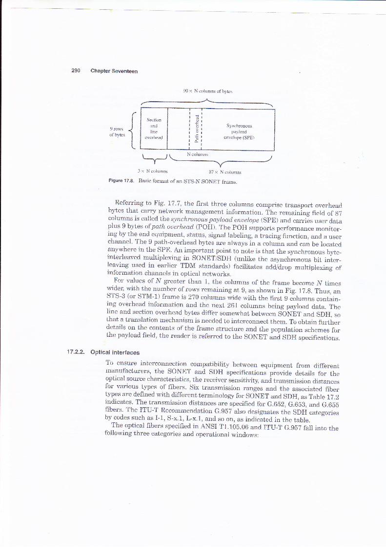
Figure't7.9. Basic forrnat of an STS_N SONET frame.
Referring to Fig. 17.7, the first three columns comprise transport overheadbytes that carry network management information. The remaining field of gTcolumns is called t]ne synchronous peyload enoelope (SpE) and carri-es user dataplus 9 bytes ofpolh ouerhead (POH). The POH supports performance monitor-ing by thlend equipment, status, signal labeling, a tracirrg function, and a userchannel. The 9 path-overhead bytes are always in a colu;n and can be locatedany'where in the SPE. An important point to note is that the synchronous byte-interleaved multiplexing in SONET/SDH (unlike the asynchronous bit inter-leaving used in earlier TDM standards) facilitates ad#drop multiplexing ofinformation channels in optical networks.
For values of N greater than 1, the columns of the frame become ]V timeswider, with the number of rows remaining at 9, as shown in Fig. 17.g. Thus, anSTS-3 (or S?M-l) frame is 2?0 columns wide with the first 9 columns contain-ing overhead information and the next 261 columns being payload data. Theline and section overhead bytes differ sornewhat between SONET and SDH, sothat a translation mechanism is needed to interconnect them. To obtain f'urtherdetails on the contents of the frame structure and the population schemes forthe payload field, the reader is referred to the SONE"
""a SOI{ specifrcations.
17.2.2. Optical interfaces
To ensure interconnection compatibility between equipment from differentmanufacturers, the soNET and sDH specifications provide details for theopticai soutce characteristics, the receiver sensitivity, urrd trnrrr*ission distancesfor various types of fibers. six transmission
"urrgu, and the associated fiber
types are de{?ned with different terrrrinotrogy for so}gr and s}H, as ?atrle 12.2indicates. The transmission distances are specified for G.652, G.6bB, and G.6bbfibers. The I?u-T Recommendation G.9b? also designates the sDli categoriesby codes such as I-1, s-x.1, L-x.1, and so on, as indicated in the tabre.
The optical fibers specifred in ANSI ?1.105.06 and ITU-T G.gbT fall inta thefollowing three categories and operational windows:
90 x N colmns of bytes
Optical Networks
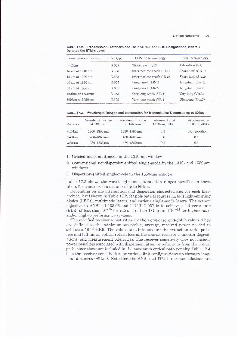
TABLE 't7.2. Transmission Distances and Their SONET and SDH Designations, Where xDenotes the STM-x Level
251
Transmission distance Fiber tlpe SONET terminologlz SDH terminoiory
= 2km
15km at 13l0nm
15km at 1550nm
40km at 1310nm
80krn at 1550nm
120km at 1550nm
160krn at 1550nm
G.652
G.653
G.653
G.655
G.655
G.655
G.655
Short-reach (SR)
Intermediate-reach (1R- 1)
Intermediate-reach (IR-Z)
Long-reach (LR-l)
Long-reach (LR-Z)
Very long-reach (VR-l)
Very long-reach (VR-Z)
Intraoffice (I-1)
Short-haul (S-x.1)
Short-haul {S-x.2)
Long-haul (L-x.1)
Long-haul (L-x.S)
Very long (V-x.3)
Ultr'aiong iU-x.3)
TABLE 17.3. Wavelength Ranges and Attenuation torTransmission Distances up to 80km
DistanceWavelength range
at 1310nmWavelength range Attenuation at
at 1550nm 1310nm, dB&mAttenuation at1550nm, dB&m
-15 krn
<40km
=80km
1260-1360nm
1260-1360nm
1280-1335nm
1430-1580nm
1430-1580nm
1480-15B0nm
CF
0.8
0.5
Not specifred
0.5
0.3
1. Graded-index multimode in the 1310-nm window
2. Conventional nondispersion-shifted single-mode in the 1310- and 1550-nmwindows
3" Dispersion-shifted single-mode in the 1550-nm window
Table 17.3 shows the wavelength and attenuation ranges specified in thesefibers for transmission distances up to 80km.
Depending on the attenuation and dispersion characteristics for each hier-archical level shown in Table 17.2, feasible optical sources include light-ernittingdiodes (LEDs), multimode lasers, and various single-mode lasers. The systemobjective in ANSI T1.105.06 and ITU-T G.957 is to achieve a bit error rate(BER) of less than 10-10 for rates less than lGbps and 10-12 for higher ratesandlor higher-performance systems-
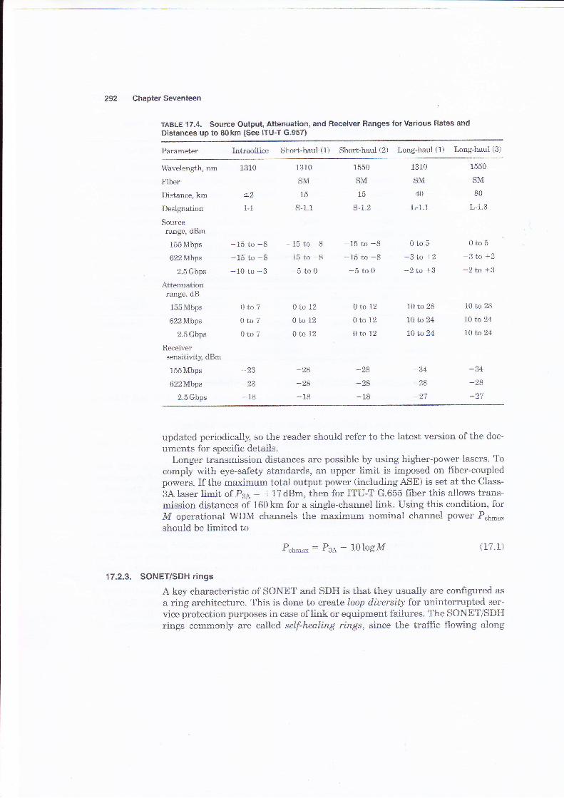
The specified receiver sensitivities are the worst-case, end-oflife values. Theyare defined as the minimum-acceptable, average, receiyed power needed toachieve a 10-10 BER. The values take into account the extinction ratio, pulserise and fali times, optical rettlrn loss at the source, receiver connector degrad-ations, and measurement tolerances. The receiver sensitivity does not includepower penalties associated'with dispersion, jitter, or reflections from the opticalpath, since these are included in the maximum optical path penalty. Tabie 17.4lists the receiver sensitivities for various link confrgurations up through long-haul distances {BSkm). Note that t}re ANSI and ITU-T reeommendations are
252 Chapter Seventeen
TABLE 17,4. Source Output, Attenuation, and Receiver Ranges forVarious Rates andDistances up to 80km {See ITU-T G.957}
Parameter Intraoffice Short-haul (1) Short-haut (2) Long-haul (l) Long-haul (3)
Wavelength, nm
Fiber
Distance, km
Designation
Sourcerange, dBm
155Mbps
622Mbps
2.5Gbps
Attenuationrange, dB
155Mbps
622Mbps
2.5 Gbps
Receiversensitivity, dBm
155Mbps
622hfbps
2.5Gbps
1310
-2I-1
-15 to -8-15 to B
-10 to -3
8to70to?0to7
*18
1310
SM
15
s-1.1
-15 to -815 to -8-5 to0
0to120to12
0to12
-99,
-28-18
*15 to -8t5 to -8-5to0
ab 12
0to12
0to12
*28
-28_18
1310
SM
40
L-1.1
0to5
-3 to +2
-2 to +3
trO to 28
l0 to 24
1A1'o24
-34
-28-27
1550
SM
80
L-1.3
0to53to+2
-Ztn +3
10 to 28
10 Lo 24
10 to 24
-34-28
1550
SM
15
s-1.2
updated periodically, so the reader should refer to the latest version ofthe doc-
uments for specifrc details.Longer transmission distances are possible by using higher-power lasers. To
comply wlth eye-safety standards, an upper limit is imposed on fiber-coupledpowers. If the maximum total output power (including ASE) is set at the Class-
3A laser limit of P3a : +L7 dBm, then for ITU-T G.655 frber this allows trans-mission distances of 160km for a single-channel link. Using this condition, forM aperational SIDM channels the maximurn nominal channel power P"h-*should be tirnited to
P.h**:Pse-lOlogM {1?.1)
17.2.3. SONETISDH rings
A key characteristic of SONET and SDH is that they usually are configured as
a ring architecture. This is done to create loop diuersily for uninterrupted ser-
vice protection purposes in case of link or equipment failures. The SONETISDHrings commonly are caled setf-heating rings, since the traffic flowing along
Oprical Networks
a certain path can be switched automatically to an alternate or standby path fol-lowing failure or degradation of the primary link segmeat.
Three main features, each with two alternatives, classi$' ail SONET/SDH rings,thus yielding eight possible combinations of ring types. First, there can beeither two or four fibers running between the nodes on a ring. Second, the oper-ating signals can travel either clockwise oniy (which is termed aunid,irectionolring) or in both directions around the ring (which is called abidirectional ring).Third, protecticn switching can be performed via either a line-switching or apath-switching scheme. Upon link failure or degradation,line switching movesall signal channels of an entire OC-N channel to a protection fiber. Conversely,path switching can move individual payload channels within an OC-N channel{e.g., an STS-1 sutrchannel in an OC-12 channel) to another path.
Of the eight possible combinations of ring [rpes, the following architectureshave become popular for SONET and SDH networks:
. ?wo-fiber:, unidirectional, path-switched ring (ca]led trro-frber UPSR)
. Two-frber or four-fiber, bidirectional, line-switched ring (called two-fiber orfour-fiber BLSR)
The common abbreviations of these configurations are given in parentheses.They also are referred to as a unidirectional ar abidirectional self-healing ring(USHR or BSHR).
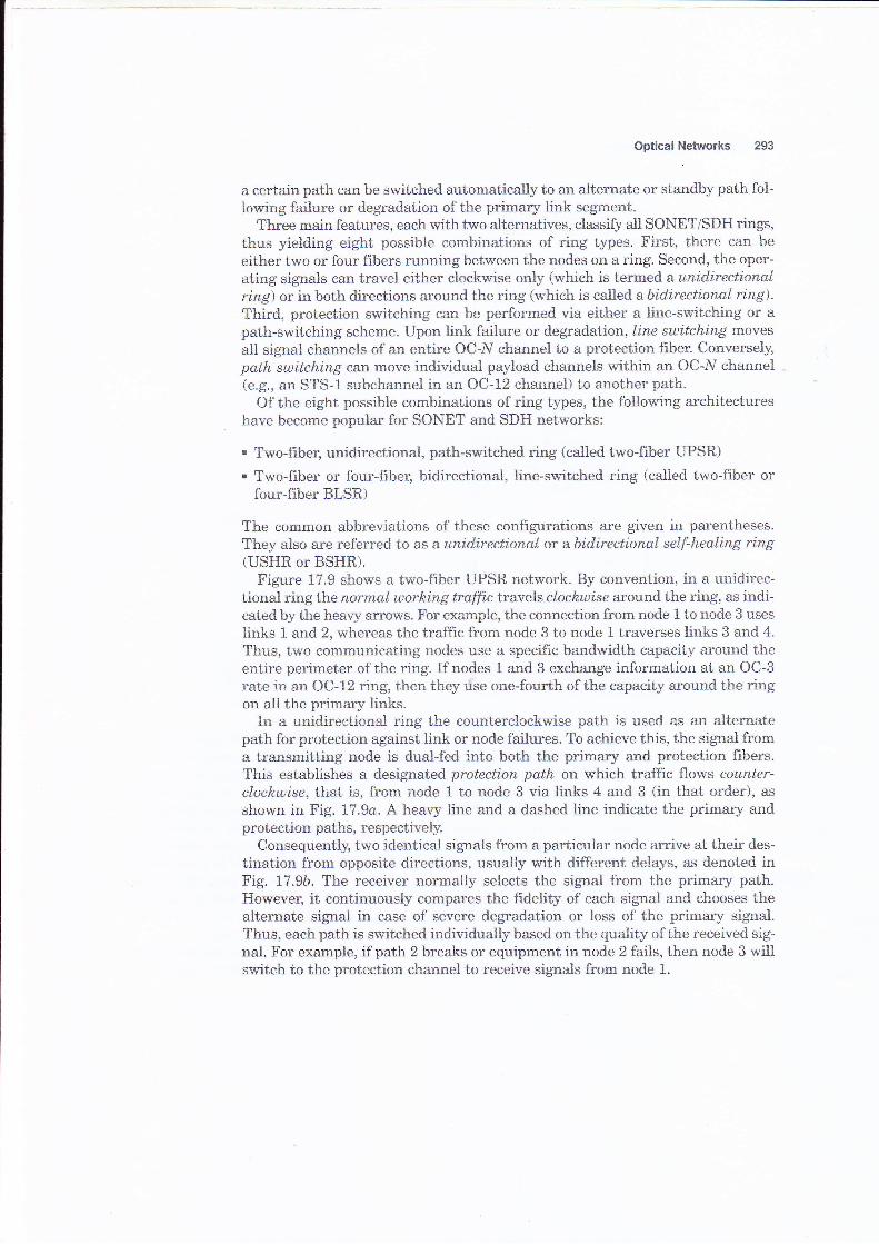
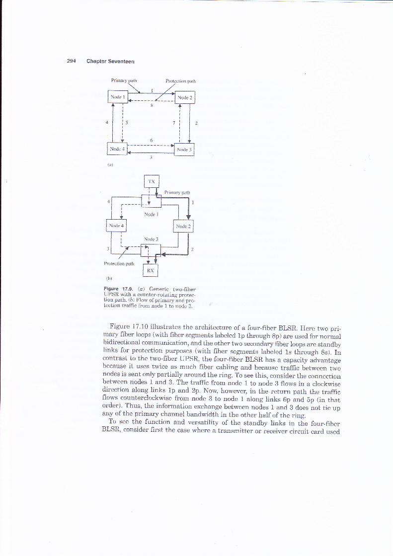
Figure 1?.9 shows a two-fiber UPSR network. By convention, in a unidirec-tional ring the normal worhirug traffic travels clochwise around the ring, as indi-cated by the heavy arrows. For example, ihe connection from node 1 to node 3 usesIinks 1 and 2, whereas the traffic from node 3 to node 1 traverses links 3 and 4.
Thus, two communicating nodes use a specifie bandwidth capaeity around theentire perimeter of the ring. If nodes 1 and 3 exchange information at an OC-Srate in an OC-12 ring then they use one-fourth of the capacrty around the ringon all the primary links.
In a unidirectional ring the counterclockrvise path is used as an alternatepath for protection against link or node failures. To achieve this, the signal froma transmitting node is dual-fed into both the primary and protection fibers.This establishes a designated protection path on which traffic flows counter-clockwise, that is, frcm node 1 to node 3 via links 4 and 3 (in that order), as
shown in Fig. 17.9a. A heavy line and a dashed line indicate the primary arrdprotection paths, respectively.
Consequently, two identical signals from a particular node arrive at their des-tination from oppcsite directions, usually with different delays, as denoted inFig. 17.9b. The receiver normaliy selects the signal from the primary path.However, it continuously compares the frdelity of each signal and chooses thealternate signai in case of severe degradation or loss of the primary signal.Thus, each path is switched individually based on the quality of the received sig-nal. For example, if path 2 breaks or equipment in node 2 fails, then node 3 willswitch to the protection channel to receive signals frorn node 1.
Chapter Seventeen
Figure 17,9, {a} Generie two-fiberUPSR vrith a counter-rotating protec-tion path. (b) Flow of primary and pro-tection traffrc from node 1 to node- B.
Figure 17.10 illustrates the architecture of a four-fiber BLSR. Here two pri-mary fiber loops (with fiber segments iabeled 1p through gp) are used for normalbidirectional communication, and the other two secondary fiber loops are standbylinks for protection purposes {with {iber segments labe}ed 1s through ss). lncontrast to the two-fiber UPSR, the four-fiber BLSR has a capacity advantagebecause it uses twice as much fitrer cabling and because traffic between twonodes is sent only partially around the ring. To see this, consider the connectionbetween nodes 1 and 3. The traffic from node 1 to nod.e B flows in a clockwisedirection along links 1p and 2p. Now, however, in the return path the trafficflows counterclockwise from node B to node 1 along tinks 6p and 5p (in thatorder). Thus, the information exchange between nodes 1 and B does not tie upany cf the primary channel bandwidth in the cther half of the ring.
To see the function and versatility of the standby links in the four-fiberBLSR, consider first the case where a transmitter or receiyer circuit card used

Optical Netvtorks 295
Primary 2-ftberbidirecticnal lo4
Figure 17.10. Arehitecture of a four-frber bidirectional line-switched ring (BI-SR).
Card failure
Figure 17.1 1. Reconfigirration of a fsur-fiber BLSR under trans-ceiver or line faitrure.
on the primary ring fails in either node 3 or 4. In this situation the affected
nodes detect a loss-of-signal condition and switch both primary {ibers connectingthern to ihe seccndary protection pair, as shown in Fig. !7.L1. The protectionsegment between nodes 3 and 4 now becomes part of the primary bidirectionalloop. The exacb same recon{iguration scenario wil} occur when the primary fiberconnecting nodes 3 and 4 breaks. Note that in either case the other links remainunaffected.
Now suppose an entire node fails, or both the primary and the protectionfibers in a given span are severed, which eould happen if they are in the same
cable duct between two nodes. In this case the nodes on either side of the failed
Serondary 2-fibertridirectional pr<rtection lcoP
i T**tioo switching
!, Node4 / \ Node3 I!
- Break in
Chapter Seventeen
Cablelai lure
Nodefailure
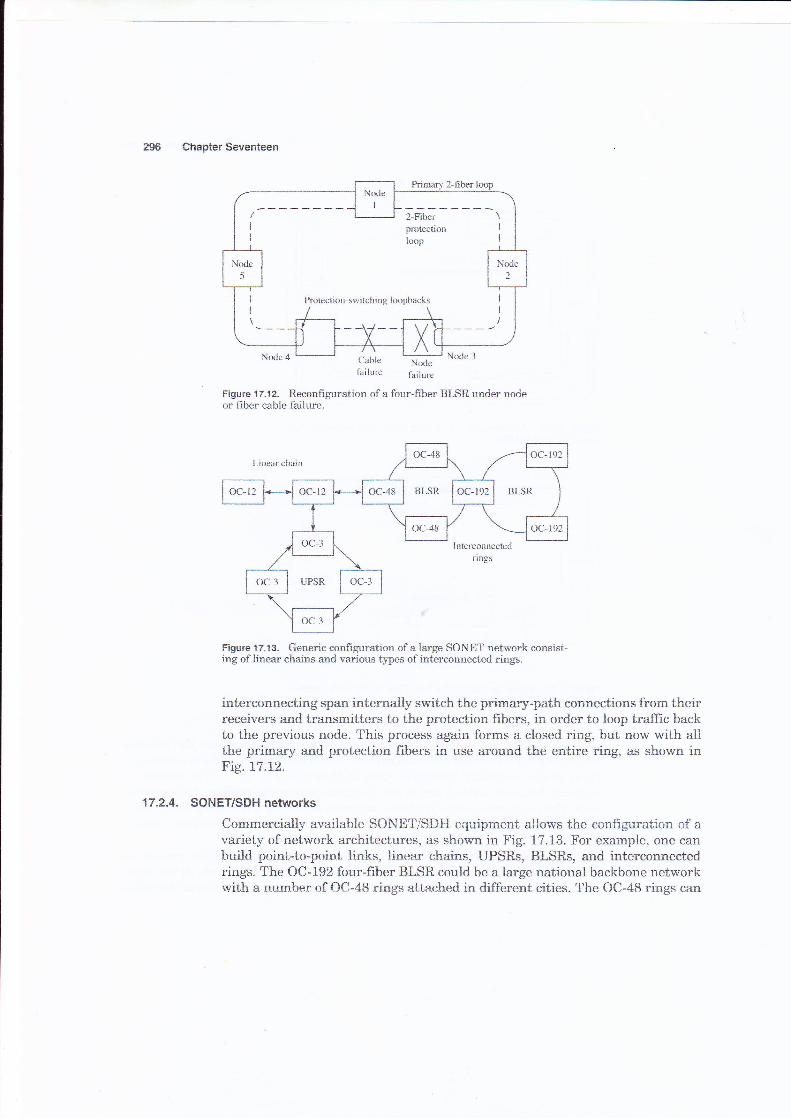
Figure 't 7.1 2. Reconfiguration of a four-fiber BLSR under nodeor filler cable faiiure.
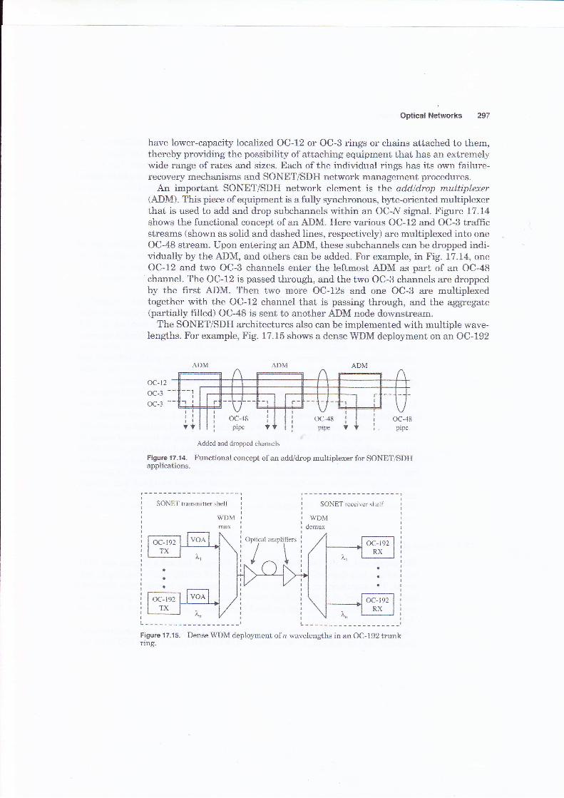
Figure 1 7.1 3. Generic confrguratioa of a large SONET network consist-ing oflinear cheins and various lpes ofinterconnected rings.
interconnecting span internally switch the primary-path connections from theirreceivers and transmitters to the protection frbers, in order to loop traffic backto the previous node. This process again forms a closed ring, but now with allthe primary and prctection fibers in use around the entire ring, as shown inFig. U.12.
17.2.4. SONET/SDH networks
Commercially available SONETISDH equipment allows the configuration of avariety of network architectures, as shown in Fig. 17.13. For example, one cantruild point-to-point links, linear chairrs, UPSRs, BLSRs, and interconneetedrings. The OC-192 four-fiber BLSR could be a large national backbone networkwith a number of OC-48 rings attaehed in different eities. The OC-48 rings can
Optical Networks
have lower-capacity localized OC-72 or OC-3 rings or chains attached to them,thereby providing the possibility of attaching equiprnent that has an extremelywide range of rates and sizes. Each of the individual rings has its own failure-recsvery meehanisms and SONET/SDH network management procedures.
An important SONET/SDH network element is the addldrap multiplexer(ADM). This pieee cf equiprnent is a firlly grnehronous, byt*.oriented multiplexerthat is used to add and drop subchannels within an OC-N signal. Figure 1-7.14
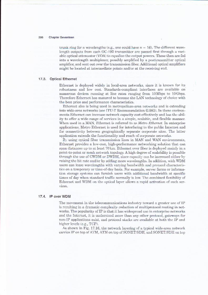
shows the functional ccncept of an ADM. Here various OC-12 and OC-3 trafficstreams (shown as solid and dashed lines, respectively) are multiplexed into oneOC-48 stream. Upon entering an ADM, these subchannels can be dropped indi-vidually by the ADM, and others can be added. For example, in Fig. 17.L4, oneOC-tz and two OC-S channels enter the leftuaost ADM as part of an OC-48channel. ?he OC-12 is passed through, and the two OC-3 channels are droppedby the first ADM. Then two more OC-12s and one OC-3 are multiplexedtogether with the AC-12 channel that is passing through, and the aggregate{partially filled) OC-48 is sent to another ADM node downstream.
The SONET/SDH architectures also can be implemented with multiple wave-lengths. For exarnple, Fig. 17.15 shows a dense WDM deployment on an OC-192
ADM ADM
{x:-12oc-3 --OC-:3 --
oc-48pipe
oc-48pipe
oc-4tipipe
Added and dropped channels
Figure 17-14. Functional concept of an add/drop multiplexer for SONETISDHapplications.
SONET transmitter shelf S0NET receiver shelf
WDMmu
Figure 17.15. DenseWDM deployment of n wavelengths in an OC-192 trunknng.
Chapter Seventeen
trunk ring for n wavelengths (e.g., one could have n: 16). The different wave-length outputs fron each OC-192 transmitter are passed first through a vari-able optical attenuator (VOA) to equalize the output powers. These then are fedinto a wavelength multiplexer, possibly amplified by a posttransmitter opticalamplifieq and sent out over the transmission frber. Additional optical amplifrersmight be located at intermediate pcints and/ar at the recerving end.
17.3" Optical Ethernet
Ethernet is deployed widely in local-area networks, since it is known for itsrobustness and low cost. Standards-compliant interfaces are available onnumerous devices running at line rates ranging from 1OMbps to 10Gbps.Therefore Ethernet has matured tc become the tr AN teehnolory of choiee withthe best price and performance characteristics.
Ethernet also is being used in metropolitan-area netwcrks and is extendinginto wide-area networks (see ITU-T Recommendation G.985). In these environ-ments Ethernet can increase network capaeity cost-effectively arrd has the abii-ity to offer a wide range of services in a simple, scalable, and flexible manner.When used in a MAN, Ether*et is referred to as Metro Ethernet.In enterpriseapplications, Metro Ethernet is used for interfacing to the public Internet andfor connectivity between geographically separaie corporate sites. The latterapplication extends the functionality and reach of corporate networks.
By using optical fiber transmission iines in MA,i$ and WAN environrnents,Ethernet provides a low-cost, high-performance networking solution that canspan distances up to at least ?Okm. Ethernet over fiber is deployed mainly in apoint-to-point or mesh network topologS'. A high degree of scalability is possiblethrough the use of CWDM or DWDM, since capacity ean be increased either byraising the bit rate and/or by adding more wavelengths. In addition, with WDMusers ean lease wavelengths with varying bandwidth and protocal charaeteris-tics on a temporary or time-of-day basis. For example, server farms or informa-tion storage systems can furnish users with additional bandwidth at specifictimes of day when standard traffic normally is low. The combined flexibility ofEthernet and WDM on the optical layer allows a rapid aetivation of such ser-vices.
17.4. lP overWDM
The movement in the telecommunications industry toward a greater use of IPis resulting in a dramatic complexity reduction of multiprctoccl routing in net-works. The popularity of IP is that it has widespread use in enterprise networksand the Internet, it is understood more than any cther protocol, gateways fornon-IP applications exist, and protocol stacks are available at both the IP andhigher levels (e.g., TCP).
As shown in Fig. t7.L6, the network layering of a typicai wide-area networkcarries IP on top of ATM, AT&{ on top of SONET/SDH, and SONET/S}H on top