macromodel quick start guide - uci department of …jsnowick/groupweb/maestro/macromodel... ·...
TRANSCRIPT

MacroModel Quick Start Guide
MacroModel 9.9
Quick Start Guide
Schrödinger Press

MacroModel Quick Start Guide Copyright © 2012 Schrödinger, LLC. All rights
reserved.
While care has been taken in the preparation of this publication, Schrödinger
assumes no responsibility for errors or omissions, or for damages resulting from
the use of the information contained herein.
BioLuminate, Canvas, CombiGlide, ConfGen, Epik, Glide, Impact, Jaguar, Liaison,
LigPrep, Maestro, Phase, Prime, PrimeX, QikProp, QikFit, QikSim, QSite, SiteMap,
Strike, and WaterMap are trademarks of Schrödinger, LLC. Schrödinger and
MacroModel are registered trademarks of Schrödinger, LLC. MCPRO is a trademark
of William L. Jorgensen. DESMOND is a trademark of D. E. Shaw Research, LLC.
Desmond is used with the permission of D. E. Shaw Research. All rights reserved.
This publication may contain the trademarks of other companies.
Schrödinger software includes software and libraries provided by third parties. For
details of the copyrights, and terms and conditions associated with such included
third party software, see the Legal Notices, or use your browser to open
$SCHRODINGER/docs/html/third_party_legal.html (Linux OS) or
%SCHRODINGER%\docs\html\third_party_legal.html (Windows OS).
This publication may refer to other third party software not included in or with
Schrödinger software ("such other third party software"), and provide links to third
party Web sites ("linked sites"). References to such other third party software or
linked sites do not constitute an endorsement by Schrödinger, LLC or its affiliates.
Use of such other third party software and linked sites may be subject to third
party license agreements and fees. Schrödinger, LLC and its affiliates have no
responsibility or liability, directly or indirectly, for such other third party software
and linked sites, or for damage resulting from the use thereof. Any warranties that
we make regarding Schrödinger products and services do not apply to such other
third party software or linked sites, or to the interaction between, or
interoperability of, Schrödinger products and services and such other third party
software.
Revision A, September 2012

Contents
Document Conventions ...................................................................................................... v
Chapter 1: Getting Started ............................................................................................... 1
1.1 About MacroModel .................................................................................................... 1
1.2 About this Manual ..................................................................................................... 1
1.3 Preparing for the Exercises ..................................................................................... 2
Chapter 2: Using Maestro................................................................................................. 5
2.1 Importing a Structure ............................................................................................... 5
2.2 Identifying, Labeling, and Deleting Structure Elements .................................... 7
2.3 Using the Find Toolbar to Identify Molecules ...................................................... 9
2.4 Displaying and Undisplaying Atoms ..................................................................... 9
2.5 Applying and Removing Atom Labels ................................................................. 11
2.6 Adjusting Bond Orders, Atom Types, and Formal Charges ............................ 12
2.7 Adding Hydrogens to a United Atom Structure ................................................. 14
2.8 Creating and Viewing Surfaces ............................................................................ 15
2.8.1 Creating a Molecular Surface of a Complex ..................................................... 15
2.8.2 Limits to a Surface ............................................................................................ 17
2.8.3 Generating a Surface for One Molecule in a Complex...................................... 18
2.8.4 Creating a Map of the Binding Site ................................................................... 19
2.9 Creating and Manipulating Atom Sets................................................................. 21
2.9.1 Defining an Atom Set by Selecting Atoms ........................................................ 21
2.9.2 Defining an Atom Set with the Atom Selection Dialog Box ............................... 22
2.9.3 Defining Atom Sets With Boolean Operations .................................................. 23
2.10 Filtering Structures: Sorting and the Plot Facility .......................................... 25
2.10.1 Generating Data.............................................................................................. 25
2.10.2 Filtering by Sorting.......................................................................................... 26
2.10.3 Filtering Using the Plot Facility........................................................................ 27
MacroModel 9.9 Quick Start Guide iii

Contents
iv
Chapter 3: Energy Calculation and Minimization ........................................... 29
3.1 Current Energy Calculations ................................................................................ 29
3.1.1 Calculating the Gas-phase Potential Energy .................................................... 29
3.1.2 Investigating Force Field Interactions ............................................................... 31
3.1.3 Calculating the Solution-phase Current Energy................................................ 32
3.2 Energy Minimization ............................................................................................... 32
3.2.1 Energy Minimization of a Single Structure ........................................................ 33
3.2.2 Comparing Structural Results by Superposition ............................................... 34
3.2.3 Energy Minimization of Multiple Structures....................................................... 35
3.2.4 Energy Minimization of a Substructure ............................................................. 37
Chapter 4: Conformational Searches ..................................................................... 41
4.1 MCMM Search .......................................................................................................... 41
4.2 Serial MCMM Conformational Search.................................................................. 42
4.3 Serial Low-Mode Search ........................................................................................ 43
4.4 Ligand Conformational Search with a Frozen Receptor .................................. 44
4.5 Substructure Conformational Search with Automatic Setup .......................... 47
4.6 Large-Scale Low-Mode Conformational Search ................................................ 49
Chapter 5: Other Calculations ..................................................................................... 51
5.1 Ligand Binding using Embrace ............................................................................ 51
5.2 Molecular Dynamics ............................................................................................... 53
5.3 Creating Energy Profiles from Coordinate Scans ............................................. 55
5.3.1 Performing a Coordinate Scan Calculation ....................................................... 55
5.3.2 Analyzing the Results of the Coordinate Scan.................................................. 56
5.4 MINTA Prediction of Free Energy ......................................................................... 57
5.5 Partition Coefficient Between Two Solvents ...................................................... 59
Getting Help ............................................................................................................................. 61
Schrödinger Suite 2012 Update 2

Document Conventions
In addition to the use of italics for names of documents, the font conventions that are used inthis document are summarized in the table below.
Links to other locations in the current document or to other PDF documents are colored likethis: Document Conventions.
In descriptions of command syntax, the following UNIX conventions are used: braces { }
enclose a choice of required items, square brackets [ ] enclose optional items, and the barsymbol | separates items in a list from which one item must be chosen. Lines of commandsyntax that wrap should be interpreted as a single command.
File name, path, and environment variable syntax is generally given with the UNIX conven-tions. To obtain the Windows conventions, replace the forward slash / with the backslash \ inpath or directory names, and replace the $ at the beginning of an environment variable with a %at each end. For example, $SCHRODINGER/maestro becomes %SCHRODINGER%\maestro.
Keyboard references are given in the Windows convention by default, with Mac equivalents inparentheses, for example CTRL+H (H). Where Mac equivalents are not given, COMMANDshould be read in place of CTRL. The convention CTRL-H is not used.
In this document, to type text means to type the required text in the specified location, and toenter text means to type the required text, then press the ENTER key.
References to literature sources are given in square brackets, like this: [10].
Font Example Use
Sans serif Project Table Names of GUI features, such as panels, menus, menu items, buttons, and labels
Monospace $SCHRODINGER/maestro File names, directory names, commands, envi-ronment variables, command input and output
Italic filename Text that the user must replace with a value
Sans serif uppercase
CTRL+H Keyboard keys
MacroModel 9.9 Quick Start Guide v

vi
Schrödinger Suite 2012 Update 2
MacroModel Quick Start Guide
Chapter 1
Chapter 1: Getting Started
1.1 About MacroModel
MacroModel 9.9 is a general purpose, force-field-based molecular modeling program withapplicability to a wide range of chemical systems. MacroModel provides multiple advancedmethods to aid in the understanding of chemical structure, energetics, and dynamics. A largeselection of force fields is included, along with the latest technical advances introduced into theOPLS force fields. Numerous minimization methods are available, enabling geometry optimi-zations for a broad selection of structural classes. A wide range of methods is available forconformational searching, which allows efficient sampling of the potential energy surface forlow-energy structures, including entire proteins. Solvation effects can be accounted for usingthe efficient continuum solvation model in MacroModel. Additional advanced features includemolecular dynamics simulations, free-energy perturbation simulations, and pure- and mixed-ensemble sampling methods.
1.2 About this Manual
This manual contains exercises designed to help you learn the basic tasks for preparing andinitiating MacroModel calculations from Maestro. Once you have worked through these exer-cises, you will have an understanding of the basic MacroModel features. The exercises aredivided into groups:
• Chapter 2 contains exercises on a number of basic operations in Maestro. • Chapter 3 contains exercises on the calculation and minimization of the energy. • Chapter 4 contains exercises on conformational searching.• Chapter 5 contains exercises on various other MacroModel capabilities.
The exercises contain only the information required for basic understanding and to completethe task at hand. For more information about a particular MacroModel feature, see the Macro-Model User Manual. To learn more about the command line MacroModel and MacroModeloperation codes, see the MacroModel Reference Manual.
Maestro comes with automatic context-sensitive help (Auto-Help), Balloon Help (tool tips), anonline help facility, and a set of manuals. For information on using Maestro, see the Maestroonline help or the Maestro User Manual.
MacroModel 9.9 Quick Start Guide 1

Chapter 1: Getting Started
2
To perform the exercises, you must have access to an installed version of Maestro 9.3 andMacroModel 9.9. For installation instructions, see the Installation Guide.
The MacroModel installation contains the structure files used in the following exercises. Theinstallation also contains sample input files, which you can use to run exercises without havingto complete all of the preceding exercises.
1.3 Preparing for the Exercises
To run the exercises, you need a working directory in which to store the input and output, andyou need to copy the input files from the installation into your working directory. This is doneautomatically in the Tutorials panel, as described below. To copy the input files manually, justunzip the macromodel zip file from the tutorials directory of your installation into yourworking directory.
On Linux, you should first set the SCHRODINGER environment variable to the Schrödinger soft-ware installation directory, if it is not already set:
If Maestro is not running, start it as follows:
• Linux: Enter the following command:
$SCHRODINGER/maestro -profile Maestro &
• Windows: Double-click the Maestro icon on the desktop.
You can also use Start → All Programs → Schrodinger-2012 → Maestro.
• Mac: Click the Maestro icon on the dock.
If it is not on the dock, drag it there from the SchrodingerSuite2012 folder in your Appli-
cations folder, or start Maestro from that folder.
Now that Maestro is running, you can start the setup.
1. Choose Help → Tutorials.
The Tutorials panel opens.
2. Ensure that the Show tutorials by option menu is set to Product, and the option menubelow is labeled Product and set to All.
3. Select MacroModel Quick Start Guide in the table.
csh/tcsh: setenv SCHRODINGER installation-path
sh/bash/ksh: export SCHRODINGER=installation-path
Schrödinger Suite 2012 Update 2

Chapter 1: Getting Started
4. Enter the directory that you want to use for the tutorial in the Copy to text box, or clickBrowse and navigate to the directory.
If the directory does not exist, it will be created for you, on confirmation. The default isyour current working directory.
5. Click Copy.
The tutorial files are copied to the specified directory, and a progress dialog box is dis-played briefly.
If you used the default directory, the files are now in your current working directory, and youcan skip the next two steps. Otherwise, you should set the working directory to the place thatyour tutorial files were copied to.
6. Choose Project → Change Directory.
7. Navigate to the directory you specified for the tutorial files, and click OK.
You can close the Tutorials panel now, and proceed with the exercises.
MacroModel 9.9 Quick Start Guide 3

4
Schrödinger Suite 2012 Update 2
poMacroModel Quick Start Guide
Chapter 2
Chapter 2: Using Maestro
The exercises in this section present a quick tour of some aspects of the Maestro interface,including the following:
• Importing a structure file• Deleting portions of a Workspace structure• Using the Find feature to locate particular structural elements• Displaying, undisplaying, and labeling atoms and molecules• Generating and displaying surfaces• Defining atom sets for use when selecting atoms
You can find additional information about Maestro in the Maestro User Manual.
Most of the exercises in this chapter use the structure in 1err.pdb, which you copied to yourworking directory.
2.1 Importing a Structure
To display an existing structure in the Workspace, you must import the structure into thecurrent project. Follow the instructions below to import the 1err protein-ligand complex intoa named project. (You can work in a scratch project, but using a named project enables you toorganize the results of your calculations.)
1. Click the Save As button on the Project toolbar.
2. In the File name text box, enter 1err.prj, then click Save.
3. Click the Import button on the Project toolbar.
The Import panel opens (see Figure 2.1). It should display the common structure files inyour working directory (Maestro, PDB, SD, MOL2).
You can also open the Import panel by choosing Project → Import Structures in the mainwindow or by choosing Table → Import → Structures in the Project Table panel.
MacroModel 9.9 Quick Start Guide 5

Chapter 2: Using Maestro
6
Figure 2.1. The Import panel.
4. Select 1err.pdb from the list of files.
5. Click Open.
The Import panel closes, and a warning dialog box appears, but it isn’t critical for thisexercise. Click OK.
When Maestro imports a PDB file, problematic parts of imported structures, such as non-stan-dard functional groups, are colored orange, red, green, or blue. For this exercise, it is not neces-sary to correct the protein structure. However, when you begin to work on other proteins, youmay want to investigate and manually adjust marked portions. See Section 3.1.6 of the MaestroUser Manual for more information.
Schrödinger Suite 2012 Update 2

Chapter 2: Using Maestro
2.2 Identifying, Labeling, and Deleting Structure Elements
This exercise demonstrates how to use Maestro’s display tools to inspect the protein-ligandcomplex and delete parts of the structure that are not needed for a calculation.
The protein-ligand complex imported in the last exercise was obtained from the Protein DataBank repository. The structure contains crystallographic water molecules, which need to beremoved. Also, the structure is dimeric, and for most purposes only the monomer is required.
To label the water molecules with the PDB name:
1. In the Workspace, right-click on an atom in one of the outlying water molecules to spot-center on the atom.
2. Zoom in on the water molecules by scrolling with the mouse wheel or by dragging withthe middle and right mouse buttons, until you have a good view of the water molecules.
3. Choose Composition from the Pick to Label button menu on the Labels toolbar.
The Atom Labels panel opens (see Figure 2.2).
Figure 2.2. The Atom Labels panel.
MacroModel 9.9 Quick Start Guide 7

Chapter 2: Using Maestro
8
4. Click Remove All to remove the current properties from the Fields list.
5. Click Add, select Residue name in the Atom Properties tab, and click OK.
6. Choose Molecules from the Pick option menu in the Label atoms section.
7. In the Workspace, select one of the outlying water molecules of the structure to display itslabel: HOH.
8. Close the Atom Labels panel.
To delete unwanted atoms:
1. Choose Waters from the Delete button menu on the Edit toolbar.
All the water molecules are deleted.
2. Click the Fit button on the Workspace toolbar.
The entire protein is now visible.
3. Pause the pointer over various atoms in the protein until you find one that is in chain B.
Information on an atom is displayed in the status area at the bottom of the main windowwhen the pointer pauses over the atom, beginning with the chain name.
4. Choose Chains from the Delete button menu, and click on an atom in chain B.
The entire chain, including the ligand, is deleted, leaving chain A.
Schrödinger Suite 2012 Update 2

Chapter 2: Using Maestro
Figure 2.3. The Find Toolbar.
2.3 Using the Find Toolbar to Identify Molecules
The imported structure contains three discrete molecules. Find and visualize the three separatemolecules with the Find toolbar:
1. If the Find toolbar is not displayed, choose Edit → Find, or press CTRL+F. (SeeFigure 2.3).
2. From the Find option menu, choose Specified atoms.
3. Enter mol.num 1 in the text box and press ENTER.
4. The view zooms to molecule number 1, and the atoms in the molecule are selected.
5. Change the number in the text box to 2 and press ENTER, to find molecule 2. Repeat formolecules 3 and 4. Molecule 4 is the ligand.
6. When you have finished finding the molecules, clear all the options in the lower left ofthe panel and close the Find panel.
2.4 Displaying and Undisplaying Atoms
By undisplaying atoms that do not contribute to active site functionality, you can more easilyexamine the active site. Atoms can be displayed and undisplayed in the Workspace using thetoolbar, the Display/Undisplay Atoms panel, or by entering an undisplayatom command withan appropriate Atom Specification Language (ASL) expression in the command input area.Below are instructions for using the toolbar. For information on the other methods, seeSection 7.5 of the Maestro User Manual.
1. Choose Select from the Display Only button menu on the Display Atoms toolbar.
The Atom Selection dialog box opens (see Figure 2.4).
2. In the Molecule tab, choose Molecule Number from the list on the left and enter 4 in theMolecule Number text box.
MacroModel 9.9 Quick Start Guide 9

Chapter 2: Using Maestro
10
Figure 2.4. The Atom Selection dialog box, Molecule tab.
3. Click Add, then click OK.
The ligand, molecule number 4, is displayed and the remaining atoms are undisplayed.
4. Choose Protein Backbone from the Also Display button menu. Repeat for Protein SideChains and for Waters.
You have now redisplayed the entire protein. However, the crystallographic water moleculeshave not been redisplayed because they were deleted, not undisplayed, in the exercise inSection 2.2 on page 7.
You can also display residues that have atoms within a specified distance of the currentlydisplayed atoms. This is useful for displaying the part of a protein that is close to a ligand.
1. Choose Molecules from the Display Sel button menu.
2. Click on an atom in the ligand to display only the ligand.
Schrödinger Suite 2012 Update 2

Chapter 2: Using Maestro
3. Choose +6 Å from the Within button menu.
For more complicated atom selections, you can use the Display/Undisplay Atoms panel(choose Workspace → Display/Undisplay Atoms).
4. Redisplay all atoms by choosing All from the Also display button menu.
2.5 Applying and Removing Atom Labels
You can apply labels to any atoms in the Workspace. You can also specify the label content,label placement, and label appearance. In the exercise in Section 2.2 on page 7, you labeledatoms with their PDB residue names. This exercise demonstrates how to apply and removevarious types of atom labels.
To apply atom labels:
1. Choose Composition from the Pick to Label button menu.
The Atom Labels panel opens.
2. Click Remove All to remove the current properties from the Fields list.
3. Click Add, select Atom number, Atom type (MacroModel), and Formal charge in the AtomProperties tab, and click OK.
4. In the Label atoms section, choose Molecules from the Pick menu.
5. In the Workspace, click on an atom in the ligand to label its atoms.
To remove atom labels:
1. From the Pick to option menu, choose Clear labels.
The Label atoms section is renamed Clear labels, to reflect the new action.
2. Click the Atom Selection button and choose Select.
The Atom Selection dialog box opens.
MacroModel 9.9 Quick Start Guide 11

Chapter 2: Using Maestro
12
3. In the Atom tab, select Element from the list on the left, then select O from the Element
list in the center.
4. Click Add, then click OK to remove the labels for all oxygen atoms.
5. In the Atom Labels panel, click Clear All Labels to remove all atom labels.
6. Close the Atom Labels panel.
2.6 Adjusting Bond Orders, Atom Types, and Formal Charges
Most PDB structures derived from X-ray crystallography data do not have hydrogen atoms,formal charges, or bond orders. When the structure is imported into Maestro, the conversionutility uses templates for assigning multiple bonds in standard residues, but cannot do so forligands. Thus you need to explicitly add multiple bonds and formal charges to the ligands ifnecessary. In this exercise you will learn how to perform these structural corrections manually,however the Protein Preparation Wizard (see the Protein Preparation Guide) is designed toautomate many of these routine tasks. The tools for these tasks are found in the Build panel oron the Build toolbar. The 1err ligand Raloxifene needs multiple bonds assigned, and the piper-idine nitrogen adjusted to be a four-coordinate, positively charged ammonium group. In thisexercise you will convert single bonds to double bonds and adjust the formal charges. In thenext exercise, the hydrogen atoms will be added.
1. Choose Molecules from the Display Sel button menu and select an atom in the ligand.
You can choose Molecule Number from the Color Scheme button menu on the Represen-tation toolbar, to help distinguish the ligand.
2. If the molecule is not displayed in wire representation, choose Molecule from the Wire
button menu on the Representation toolbar and pick an atom in the ligand.
3. Choose Element from the Color Scheme button menu.
4. Click the Build button on the Manager toolbar, or choose Window → Toolbars → Build.
Schrödinger Suite 2012 Update 2

Chapter 2: Using Maestro
Figure 2.5. The raloxifene molecule after fixing bond orders and formal charge.
5. Click the + Bond Order button on the Build toolbar.
6. Click on the aryl C–C bonds that need to be converted to double bonds.
There are two phenyl rings and a fused ring.
7. Click on the carbonyl C–O bond.
8. Click the + Formal Chg button on the Build toolbar.
9. Click on the nitrogen atom of the piperidine in the Workspace.
The formal charge of the nitrogen atom is now +1, and the atom type is automaticallyadjusted. To check the formal charge, choose Formal Charge from the Label All buttonmenu. Choose Delete Labels from the Label All button menu to remove the label.
Maestro also provides a tool for automatic assignment of bond orders. To use it, choose Tools
→ Assign Bond Orders. Automatic assignments should always be checked, because the rulesthat are used for the assignments cannot cover every possibility.
MacroModel 9.9 Quick Start Guide 13
Chapter 2: Using Maestro
14
2.7 Adding Hydrogens to a United Atom Structure
Modern force fields use all-atom structures, and Maestro contains a facility to rationally addthe appropriate number of hydrogens to carbon atoms with approximately the correct geom-etry. This exercise demonstrates how to use the tools in the Add Hydrogens - Advanced panel toadd hydrogens to the structure in the Workspace.
1. Choose Edit → Add Hydrogens → Advanced.
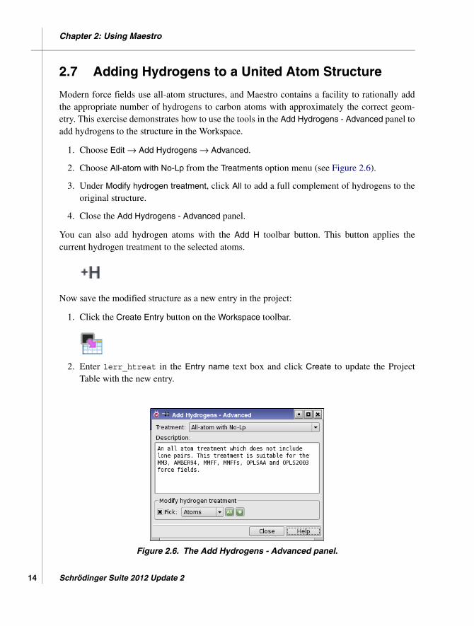
2. Choose All-atom with No-Lp from the Treatments option menu (see Figure 2.6).
3. Under Modify hydrogen treatment, click All to add a full complement of hydrogens to theoriginal structure.
4. Close the Add Hydrogens - Advanced panel.
You can also add hydrogen atoms with the Add H toolbar button. This button applies thecurrent hydrogen treatment to the selected atoms.
Now save the modified structure as a new entry in the project:
1. Click the Create Entry button on the Workspace toolbar.
2. Enter 1err_htreat in the Entry name text box and click Create to update the ProjectTable with the new entry.
Figure 2.6. The Add Hydrogens - Advanced panel.
Schrödinger Suite 2012 Update 2

Chapter 2: Using Maestro
2.8 Creating and Viewing Surfaces
Examining the surface of a molecule frequently leads to valuable insights. Maestro can createseveral surface types. Surfaces can be rendered in different styles, color schemes, and transpar-ency. Maestro surfaces are associated with project entries.
This set of exercises uses the 1err.prj project from the previous section. If you are startingthe tutorial at this point, follow the instructions in Section 2.1, Section 2.2, Section 2.6, andSection 2.7 to set up the project for these exercises.
2.8.1 Creating a Molecular Surface of a Complex
Maestro can create molecular surfaces that represent solvent-accessible regions of an entry.The molecular surface is a Connolly surface where a probe, typically with a radius of 1.4 Å, isrolled over the molecule. The surface is defined by the contact of the probe’s outer radius andthe molecule’s van der Waals radius.
To generate a molecular surface for all atoms in the entry:
1. Open the Project Table panel (Table button on the Project toolbar).
2. Click the In column for the 1err entry to include it in the Workspace.
Figure 2.7. The Molecular Surface panel.
MacroModel 9.9 Quick Start Guide 15

Chapter 2: Using Maestro
16
3. Choose Workspace → Surface → Molecular Surface in the main window.
The Molecular Surface panel opens (see Figure 2.7).
4. Under Atoms for surface display, choose Entries from the Pick menu.
5. Choose Entry from the Surface Context option menu.
The surface context describes the atoms for which the surface is created. The surface dis-play describes the atoms for which the resulting surface is displayed. You can change theatoms for which the surface is displayed after surface generation by using the Limit fea-ture, which you will do in the next exercise.
6. In the Workspace, select any atom in the entry.
7. Click Create Surface.
When the surface generation is complete, the surface is displayed in the Workspace. Ifyou have the preference set for it, the Manage Surfaces panel opens (see Figure 2.8).
You can experiment with the surfaces by doing any of the following:
• Generate the same surface with High image quality.
This calculation takes longer to generate, but the resulting surface has superior quality.Also, the resulting high quality surface may be slower to rotate depending on your work-station resources.
• In the Manage Surfaces panel, click Display Options and experiment with different stylesand color schemes.
The Partial Charge color scheme uses white until a calculation is performed. The struc-ture was imported from a PDB record, which has no information about the fractionalatomic charges. Therefore, these must be calculated before Maestro can render the partialcharge values on the surface. To use the partial charges from the OPLS_2005 force field,you can choose Assign Partial Charges from the Tools menu.
Figure 2.8. The Manage Surfaces panel.
Schrödinger Suite 2012 Update 2
Chapter 2: Using Maestro
2.8.2 Limits to a Surface
Frequently the entire surface of an entry is not required. Instead of creating another surfacewith a smaller subset of atoms, you can display a portion of a generated surface using the Limit
panel. This exercise demonstrates how to limit the surface generated in the previous exercisefrom the entire entry to a smaller section of the entry.
1. In the table, click the V field of the first row to display the surface.
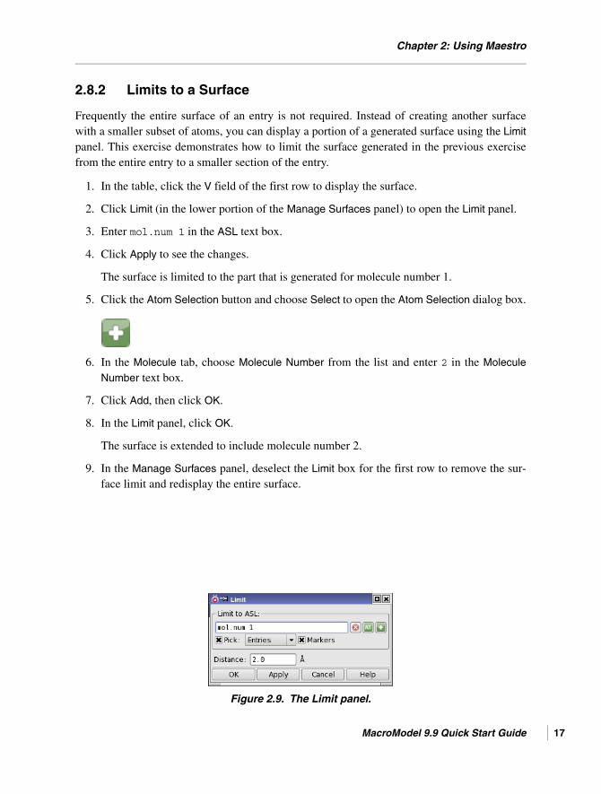
2. Click Limit (in the lower portion of the Manage Surfaces panel) to open the Limit panel.
3. Enter mol.num 1 in the ASL text box.
4. Click Apply to see the changes.
The surface is limited to the part that is generated for molecule number 1.
5. Click the Atom Selection button and choose Select to open the Atom Selection dialog box.
6. In the Molecule tab, choose Molecule Number from the list and enter 2 in the Molecule
Number text box.
7. Click Add, then click OK.
8. In the Limit panel, click OK.
The surface is extended to include molecule number 2.
9. In the Manage Surfaces panel, deselect the Limit box for the first row to remove the sur-face limit and redisplay the entire surface.
Figure 2.9. The Limit panel.
MacroModel 9.9 Quick Start Guide 17

Chapter 2: Using Maestro
18
2.8.3 Generating a Surface for One Molecule in a Complex
An entry can be composed of multiple molecules, such as a co-crystallized receptor-ligandcomplex. Maestro is capable of generating a surface using a subset of atoms in the entry. In thisexample, you will use the 1err entry to create a surface of just the atoms near the binding site,ignoring the ligand.
1. Choose Workspace → Surface → Molecular Surface in the main window.
2. Under Atoms for surface display, click the Clear button to clear the ASL text box.
3. Click the Atom Selection button and choose Select to open the Atom Selection dialog box.
4. In the Molecule tab, select Molecule Number from the list on the left and enter 4 in theMolecule Number text box.
5. Click Add.
6. Click Proximity.
The Proximity dialog box opens (see Figure 2.10).
7. Under Proximity, select Within and Angstroms, and enter 5.0 in the text box.
8. Under Fill, select Residues and select Exclude source.
9. Click OK in the Proximity dialog box and in the Atom Selection dialog box.
10. In the Molecular Surface panel, under Surface context, select Molecule.
11. Click Create Surface.
The resulting surface clearly defines the topology of the binding site.
Figure 2.10. The Proximity dialog box.
Schrödinger Suite 2012 Update 2
Chapter 2: Using Maestro
12. Close the Molecular Surface panel.
In the Manage Surfaces panel, you can click Display Options and color the surface bypartial charge or residue charge to visualize the electrostatics topology. You can alsochange the style or transparency to see the atoms under the surface. When you are fin-ished, close the Display Options panel and the Manage Surfaces panel.
13. Choose Workspace → Surface → Undisplay All.
2.8.4 Creating a Map of the Binding Site
Maestro can be used to create “maps” of receptors. The map shows hydrophobic and hydro-philic regions, and is a tremendous asset when manually docking or adjusting ligands in areceptor. For this exercise, use the structure that was given the hydrogen treatment and map theregion near the ligand. The atoms in the ligand do not need to be mapped, so they are excludedfrom the structure to map, but the ligand makes a logical center to place the bounding box.
1. Open the Project Table panel (Table button, Project → Show Table, or press CTRL+T).
2. Click the In box of the 1err_htreat entry to display it in the Workspace.
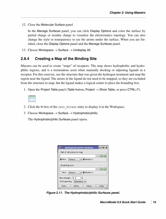
3. Choose Workspace → Surface → Hydrophobic/philic.
The Hydrophobic/philic Surfaces panel opens.
Figure 2.11. The Hydrophobic/philic Surfaces panel.
MacroModel 9.9 Quick Start Guide 19

Chapter 2: Using Maestro
20
4. In the Part of structure to map section, click the Atom Selection button, then click Select.
The Atom Selection dialog box opens.
5. In the Molecule tab, choose Molecule Number from the list on the left and enter 3 in theMolecule Number text box.
6. Click Add.
7. Click Proximity to open the Proximity dialog box.
8. Under Proximity, select Within and Angstroms, and enter 5.0 in the text box.
9. Under Fill, select Residues and select Exclude source.
10. Click OK in the Proximity dialog box and in the Atom Selection dialog box.
11. In the Hydrophobic/philic Surfaces panel, under Bounding box, choose Molecules from thePick menu and select an atom in the ligand.
12. Enter 6.0 in the Box margin text box and choose Standard from the Grid Spacing optionmenu.
13. Click Start to open the Start Job dialog box.
The Start dialog box opens. You can keep the default settings.
14. Click Start to start the job.
15. Enter sitemap1SHD in the Name text box.
16. Click Start to launch the job.
When the job finishes, the surface is displayed in the Workspace and the Manage Sur-
faces panel opens.
17. In the Manage Surfaces panel, experiment with the transparency and the isovalue. Forexample, select the philic surface in the table and enter -15.0 in the Isovalue text boxat the bottom of the panel. Enter -0.3 for the phobic isovalue.
18. When you have finished, close the Manage Surfaces panel and the Hydrophobic/philic
Surfaces panel.
Schrödinger Suite 2012 Update 2

Chapter 2: Using Maestro
2.9 Creating and Manipulating Atom Sets
Defining subsets of atoms can be useful for many analysis and visualization tasks as well as forpreparing MacroModel calculations. The Sets panel allows you to create and manipulate setsusing the full range of atom selection tools. Once created, sets can be used in the Atom Selec-
tion dialog box or from relevant Pick menus. Sets are saved within a Maestro project. To usedefined sets in another project, you can write them to a file using the Write button, then readthem into the new project using the Read button.
These exercises use the all-atom protein-ligand complex in 1err.mae:
1. Choose New from the Project menu and name the project 1errsets.
2. Import the structure from 1err_htreat.mae.
2.9.1 Defining an Atom Set by Selecting Atoms
With the contents of 1err_htreat.mae displayed in the Workspace, make a set that includesall atoms in the ligand:
Set 1: Ligand
1. Choose Tools → Sets.
The Sets panel opens.
2. Click New (in the lower portion of the panel).
Figure 2.12. The Sets panel.
MacroModel 9.9 Quick Start Guide 21
Chapter 2: Using Maestro
22
3. Enter ligand in the Set name text box, and click OK.
A new set is created, named ligand.
4. In the Sets panel, under Atoms for set, select Markers (see Figure 2.12).
5. Choose Molecules from the Pick menu.
6. In the Workspace, select an atom in the ligand to define the ligand set.
If you need to identify the ligand, color the atoms by molecule number, or use the Find
Atoms panel described on page 9. If you do use Find Atoms, deselect Mark found atoms
once you have selected the desired atom.
Maestro highlights the atoms in the ligand set in green. Highlights are displayed as lines anddots, or as boxes, depending on the molecular representation of the atoms and bonds.
2.9.2 Defining an Atom Set with the Atom Selection Dialog Box
This exercise uses the Atom Selection dialog box to define more complex sets of atoms.
Set 2: Glycine residues
Create a set that contains all glycine residues in the structure:
1. Create a new set named glycine.
2. In the Sets panel, select Markers.
3. Under Atoms for set, click the Atom Selection button, then click Select.
The Atom Selection dialog box opens.
4. In the Residue tab, select Residue Type from the list on the left, then select GLY from theResidue Type list in the center.
5. Click Add, then click OK.
You can switch between sets by selecting a set from the list at the top of the Sets panel.
Set 3: All residues with atoms within 5 Å of the ligand
Create a set containing the ligand and all atoms in complete residues within 5.0 Å of theligand:
1. Create a new set named lig+5A.
Schrödinger Suite 2012 Update 2

Chapter 2: Using Maestro
2. Under Atoms for set, click the Atom Selection button and choose Select.
The Atom Selection dialog box opens.
3. In the Set tab, select User-defined from the list on the left, then select ligand from theUser-defined list in the center, and click Add.
4. Click the Proximity button.
The Proximity dialog box opens.
5. Under Proximity, select Within and Angstroms, and enter 5.0 in the text box.
6. Under Fill, select Residues.
7. Click OK in the Proximity dialog box and in the Atom Selection dialog box.
The lig+5A set is defined.
Set 4: Alpha carbons
Create a set of all the alpha-carbon atoms in the structure (atoms with a PDB atom type C-alpha):
1. Create a new set named alphaC.
2. Under Atoms for set, click the Atom Selection button and choose Select.
The Atom Selection dialog box opens.
3. In the Atom tab, select PDB type from the list on the left, then select CA from the PDB
type list in the center.
4. Click Add, then click OK to define the alphaC set.
2.9.3 Defining Atom Sets With Boolean Operations
New sets can be created from existing sets using Boolean operations. If you do not alreadyhave the Sets panel displayed, open it from the Tools menu.
MacroModel 9.9 Quick Start Guide 23

Chapter 2: Using Maestro
24
Set 5: NOT the ligand and NOT within 5 Å
Create a new set that contains all atoms that are neither in the ligand molecule nor within 5 Åof the ligand:
1. Create a new set named frozen.
2. Under Atoms for set, click the Atom Selection button and choose Select.
The Atom Selection dialog box opens.
3. In the Sets tab, select User-defined from the list on the left, then select lig+5A from theUser-defined list in the center.
4. Click Subtract.
5. Click OK to define the frozen set.
This set could be used to specify those atoms to be fixed or frozen in a MacroModel calcula-tion.
Set 6: The ligand and all the glycine residues
Create a set containing the atoms in the ligand and in the glycine residues:
1. Create a new set named lig_or_gly.
2. Under Atoms for set, click the Atom Selection button and choose Select.
The Atom Selection dialog box opens.
3. In the Sets tab, select User-defined from the list on the left, then select ligand from theUser-defined list in the center.
4. Click Add.
5. In the Residue tab, select Residue Type from the list on the left, then select GLY from theResidue Type list in the center.
6. Click Add, then OK to define the lig_or_gly set.
Set 7: All glycine residues in the lig+5A set
Create a set containing only atoms in the glycine residues within the lig+5A set:
Schrödinger Suite 2012 Update 2
Chapter 2: Using Maestro
1. Create a new set named lig_and_gly.
2. Under Atoms for set, click the Atom Selection button and choose Select.
The Atom Selection dialog box opens.
3. In the Sets tab, select User-defined from the list on the left, then select glycine from theUser-defined list in the center.
4. Click Add.
5. In the Sets tab, select User-defined from the list on the left, then select lig+5A from theUser-defined list in the center.
6. Click Intersect, then OK to define the lig_and_gly set.
2.10 Filtering Structures: Sorting and the Plot Facility
It is often useful to identify subsets of a group of structures based on properties such as energyor dihedral angle, which can be stored as properties in the Project Table. Energetic propertiesare generated from the results of calculations and incorporated automatically into the ProjectTable. In addition, geometric properties can be created from the Measurements panel andapplied to selected entries in the Project Table by selecting Create property for selected entries
when making the measurement selection.
Once the properties have been incorporated into the Project Table, there are two independentmethods to filter the structures based on a range of the properties. The first method is to use theSort facility to sort the structures in the Project Table by property value in increasing ordecreasing order. The second method is to use the Plot facility and graphically select the struc-tures based on the property values.
2.10.1 Generating Data
This exercise demonstrates how to create properties from measurements for a set ofconformers. The properties are automatically added to the Project Table.
1. Import the structures in Filter.mae, using the directions in Section 2.1 on page 5.
The structures are imported as a new entry group, and are selected.
2. Include one of the entries in the Workspace (click the In column).
3. Choose Tools → Measurements to open the Measurements panel.
MacroModel 9.9 Quick Start Guide 25
Chapter 2: Using Maestro
26
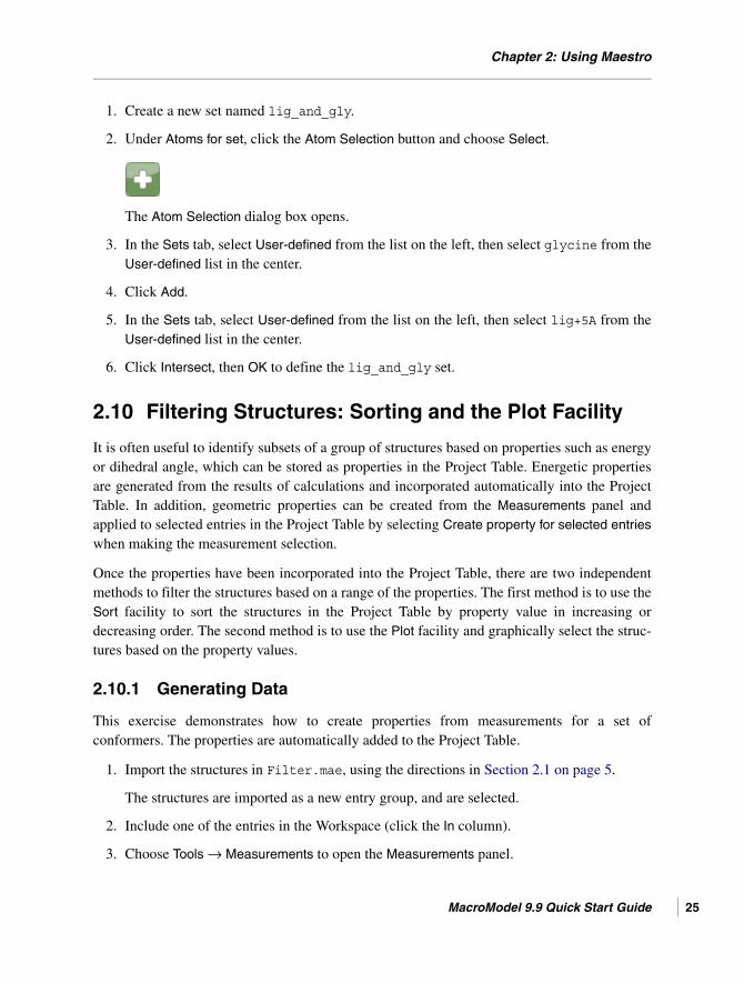
4. Select Create property for selected entries (see Figure 2.13).
5. Choose Atoms or Bonds from the Pick menu and select the four atoms or the three bondsthat define the torsion of interest.
When the torsion is defined, Maestro calculates the dihedral angle for each selected entryand transfers the data to the Project Table as a new property.
6. Close the Measurements panel.
2.10.2 Filtering by Sorting
This exercise demonstrates how to sort the structures based on the dihedral angle generated inthe previous section.
1. In the Project Table, select the entries to be sorted.
You can use shift-click and control-click to select a range of items. Select the entries forwhich you created properties in the previous section (these should already be selected).
2. Right-click on the column heading of the Dihedral property that you created, and chooseSort → Selected Rows.
The entries in the Project Table are reordered based on the sort criteria.
Figure 2.13. The Measurements panel showing the Dihedrals tab.
Schrödinger Suite 2012 Update 2

Chapter 2: Using Maestro
You can then select a subset of entries with the desired range of properties. These structurescan be written to disk or investigated further.
2.10.3 Filtering Using the Plot Facility
This exercise demonstrates how to plot the dihedral angle generated in the previous section andselect the desired entries from the plot.
1. In the Project Table, select the structures to be filtered.
2. Click the Plot button on the toolbar.
3. The Manage Plots panel opens.
4. Click New Scatter Plot.
A Scatter Plot panel opens. A new scatter plot is created, with the name Scatter-1 (seeFigure 2.14). You can rename it by selecting it and clicking Rename in the Manage Plots
panel.
5. Choose Entry ID from the X-axis option menu.
6. Choose the recently defined dihedral angle from the Y-axis option menu.
Once you have selected properties for the axes, the points are plotted in the default style.
Figure 2.14. The Scatter Plot panel.
MacroModel 9.9 Quick Start Guide 27

Chapter 2: Using Maestro
28
7. Choose your preferred plot and drawing styles.
8. In the Scatter Plot panel, click Rename.
9. Change the name to Filter, and click OK.
10. Click the Pick to select entries button on the Scatter Plot toolbar.
Circles are placed around the plot symbols, showing which entries are selected.
11. Click or drag to select a set of points corresponding to a range of dihedral angle values.
The corresponding entries are selected in the Project Table, and the plot symbols for arecircled only for the selected entries.
Similarly, you can include entries in the Workspace with the Pick to include entries button.
Schrödinger Suite 2012 Update 2

MacroModel Quick Start Guide
Chapter 3
Chapter 3: Energy Calculation and Minimization
3.1 Current Energy Calculations
Many types of energetic calculations are available using MacroModel. This section introducesthe MacroModel energetic panels and basic energetic parameters. These exercises calculate thecurrent molecular mechanics energy of a structure in gas phase, then in solution phase.
Before starting the calculations, import the substituted thymine structure from Ecalc.mae,which you copied to your working directory in Section 1.3 on page 2. If you have not copiedthese files, do so now. See Section 2.1 on page 5 for instructions on importing structures.
3.1.1 Calculating the Gas-phase Potential Energy
1. Choose Applications → MacroModel → Current Energy.
2. Choose Workspace (included entries) from the Use structures from option menu.
3. In the Potential tab, choose MMFFs from the Force Field option menu and choose None
from the Solvent option menu.
4. In the ECalc tab, choose Complete from the Energy Listing option menu.
5. Click Start.
The Start dialog box opens (see Figure 3.1).
6. Choose Replace existing entries from the Incorporate option menu.
7. Enter Ecalc in the Name text box.
Figure 3.1. The Start dialog box.
MacroModel 9.9 Quick Start Guide 29
Chapter 3: Energy Calculation and Minimization
30
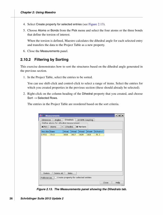
Figure 3.2. The Current Energy panel showing the Potential tab.
8. Click Start to launch the job.
The energetic settings you selected instruct the Maestro job control facility to use the contentsof the Workspace as input to perform a current energy calculation and to replace the entry thatis in the Workspace with the structural results of the calculation. The settings also instructMaestro to use the MMFFs force field, not to use a solution model (since this is a gas phasecalculation), and to generate a complete listing of the molecular mechanics energy terms.
The job finishes quickly, and the results are incorporated into the project. Since you selectedReplace existing entries, no new entries are added to the Project Table. Job files for this calcu-lation are placed in your working directory or the directory you chose for output files. Thedetailed energy listing is written to a separate file, Ecalc-out.mmo.
Schrödinger Suite 2012 Update 2

Chapter 3: Energy Calculation and Minimization
Figure 3.3. The Stretch panel.
3.1.2 Investigating Force Field Interactions
1. Choose Tools → Force Field Viewer.
2. Click Browse, select Ecalc-out.mmo from the Files list, and click Open.
3. Click Stretch to open the Stretch panel (see Figure 3.3).
4. Click on a numbered pair in the list on the left to select a stretching interaction and dis-play it in the Workspace with a magnifying glass icon.
5. To sort the stretching interactions, select Sort by Energy in the lower center portion of thepanel.
The list of stretching interactions is re-sorted so that the stretch with the lowest energy(that is, the least strained atom pair) is at the top of the list.
6. To investigate a particular stretching interaction, choose Bond from the Define Stretch
pick menu and click on the desired bond in the Workspace.
7. To view stretching interactions by parameter quality, select the desired quality level fromthe Show option menu. View relevant force field parameters by clicking Show force field.This feature has limited utility for the BMFF force fields (MMFF and OPLS_2001).
The other panels opened from the Force Field Viewer panel are similar to the Stretch panel. Youcan experiment with bond angle, electrostatic, and other parameters.
8. When you have finished, close the Stretch panel and the Force Field Viewer.
9. Click the Clear Workspace button on the toolbar.
MacroModel 9.9 Quick Start Guide 31

Chapter 3: Energy Calculation and Minimization
32
3.1.3 Calculating the Solution-phase Current Energy
1. Include the Ecalc entry in the Workspace.
2. Choose MacroModel → Current Energy from the Applications menu.
3. Choose Workspace (included entry) from the Use structures from option menu.
4. In the Potential tab, choose MMFFs from the Force Field option menu, and choose Waterfrom the Solvent option menu.
5. Enter 1.0 in the Dielectric constant text box.
For all calculations using the GB/SA solvation model, the constant dielectric treatment isautomatically used for the electrostatic part of the calculation. We recommend using alow molecular dielectric constant (for example, 1.0).
6. Click the ECalc tab and choose None from the Energy Listing option menu.
7. Click Start to open the Start dialog box.
8. Under Incorporate, select Append new entries as a new group.
9. In the Name text box, type EcalcSolv.
10. Click Start to launch the job.
Because you selected the Append new entries option, when the job finishes, a new entry isadded to the Project Table with the total potential energy as a property. You can use the outputin the Monitor panel or in the output Ecalc.log and EcalcSolv.log files to examine thedetails of the energies for the gas-phase and solution-phase calculations.
3.2 Energy Minimization
MacroModel energy minimizations are set up from the Minimization and Multiple Minimization
panels within Maestro. Minimization calculations can be performed on single structures andmulti-structure collections. In addition, for single structure calculations, the MacroModelsubstructure facility can be used to select fixed and frozen atoms for the minimization of asubset of atoms within a large structure.
For the next two exercises, you can either use the structure from Section 3.1.3 or importMini.mae from your working directory. The entry title is Ecalc. See Section 2.1 on page 5 forinstructions on importing structures.
Schrödinger Suite 2012 Update 2

Chapter 3: Energy Calculation and Minimization
Figure 3.4. The Minimization panel showing the Mini tab.
3.2.1 Energy Minimization of a Single Structure
1. Choose Applications → MacroModel → Minimization.
2. Choose Workspace (included entry) from the Use structures from option menu.
3. Click Start to open the Start dialog box.
4. Under Incorporate, select Append new entries individually.
5. In the Name text box, type Mini.
6. Click Start to launch the job.
An intermediate structure is displayed in the Workspace with the atoms colored according tothe energy gradient of the minimization at the time of monitoring. After job completion, thefinal minimized structure is incorporated into the project as a new entry. If you wish to changethe default minimization setting, click the Mini tab.
MacroModel 9.9 Quick Start Guide 33

Chapter 3: Energy Calculation and Minimization
34
3.2.2 Comparing Structural Results by Superposition
One useful way of comparing structural results is to superimpose them. Maestro provides toolsfor superimposing molecules based on a selection of atoms. For a pair of molecules, you canselect the corresponding atoms manually, and Maestro superimposes them by minimizing theRMSD of the selected atom distances. You can also select atoms in one structure using theAtom Selection dialog box or ASL and use this set as the basis of superposition. The atomspecification is applied to each entry included in the Workspace. This is useful for groups ofconformers, but may have unintended results for non-conformers. Superposition is discussed indetail in Section 10.3 of the Maestro User Manual. The following exercise demonstrates super-position for two conformers.
1. Click the Clear button on the Workspace toolbar.
2. Open the Project Table panel (Table button on the Project toolbar, choose Project → Show
Table, or type CTRL+T).
3. Click the In column for the unminimized job input structure.
4. Control-click the In column for the minimized output structure.
The two structures are superimposed in the Workspace, but do not necessarily have thebest alignment.
5. Choose Tools → Superposition.
The Superposition panel opens.
6. Click the ASL tab.
7. In the Superimpose by ASL text box, enter the expression not atom.element H andpress RETURN. (see Figure 3.5).
The minimized structure is superimposed on the input structure, using only the non-hydrogen (heavy) atoms.
8. Close the Superposition panel.
Schrödinger Suite 2012 Update 2

Chapter 3: Energy Calculation and Minimization
Figure 3.5. The Superposition panel.
3.2.3 Energy Minimization of Multiple Structures
A collection of structures, either conformers or non-conformers, can be minimized in onecomputation using the Multiple Minimization panel.
1. Click the Import button on the Project toolbar.
The Import panel opens.
2. If the options are not displayed, click Options.
3. Ensure that Import all structures is selected.
4. Select MultMini.mae from the list of files, and click Open.
This file contains 10 small molecular structures, which are imported as a new groupnamed MultMini.
5. Open the Project Table panel.
MacroModel 9.9 Quick Start Guide 35

Chapter 3: Energy Calculation and Minimization
36
Figure 3.6. The Multiple Minimization panel showing the Mult tab.
6. Ensure that all 10 structures are selected in the Project Table.
7. Choose Applications → MacroModel → Multiple Minimization in the main window.
8. Choose Project Table (selected entries) from the Use structures from option menu (seeFigure 3.6).
9. Click Start to open the Start dialog box.
10. Under Incorporate, select Replace existing entries.
11. In the Name text box, type MultMini.
12. Click Start to launch the job.
This job uses the selected entries as the input structure file and replaces the input entries in theProject Table with the resulting energy minimized structures at the conclusion of the job.
For multi-conformer computations, you can eliminate duplicate minima and reduce the outputby using the tools in the Mult tab of the Multiple Minimization panel to define an energeticwindow and identify comparison atoms.
Schrödinger Suite 2012 Update 2

Chapter 3: Energy Calculation and Minimization
3.2.4 Energy Minimization of a Substructure
The time required to minimize large structures can be drastically reduced by focusing on aparticularly important section of the structure and restraining, freezing, or ignoring the rest.This exercise uses the protein-ligand complex from Section 2.1 to perform a substructure mini-mization. The ligand and all residues within 5.0 Å of the ligand are freely minimized. Theatoms between 5.0 Å and 10.0 Å from the ligand are restrained, while the atoms between10.0 Å and 15.0 Å from the ligand are frozen. The remaining atoms are ignored. For moreinformation on the Substructure facility, see Section 4.3.3 of the MacroModel User Manual.
1. Click the Clear Workspace button on the toolbar.
2. Import the structure in SubsMini.mae from your working directory.
The ligand in this complex is molecule number 4.
First, you will create an atom set for use in the definition of the substructures:
1. Choose Tools → Sets.
The Sets panel opens.
2. Click New (in the lower portion of the panel).
3. Enter lig+5A in the Set name text box, and click OK.
A new set is created, named lig+5A.
4. In the Sets panel, under Atoms for set, select Markers.
5. Choose Molecules from the Pick menu.
6. In the Workspace, select an atom in the ligand.
If you need to identify the ligand, color the atoms by molecule number, or use the Find
Atoms panel described in Section 2.3 on page 9. If you do use Find Atoms, deselect Mark
found atoms once you have selected the desired atom.
7. In the Sets panel, under Atoms for set, click the Atom Selection button and choose Select.
The Atom Selection dialog box opens.
MacroModel 9.9 Quick Start Guide 37

Chapter 3: Energy Calculation and Minimization
38
Figure 3.7. The Minimization panel showing the Substructure tab.
8. In the Molecule tab, click the Proximity button.
The Proximity dialog box opens.
9. Under Proximity, select Within and Angstroms, and enter 5.0 in the text box.
10. Under Fill, select Residues.
11. Click OK in the Proximity dialog box and in the Atom Selection dialog box.
The lig+5A set is now defined, and you can proceed to set up the job:
12. Choose MacroModel → Minimization from the Applications menu.
13. Choose Workspace (included entry) from the Use structures from option menu.
14. In the Potential tab, choose OPLS_2001 from the Force field option menu.
15. In the Mini tab, enter 5000 in the Maximum iterations text box.
16. In the Substructure tab (see Figure 3.7), under Freely moving atoms (substructure), clickthe Atom Selections button and choose Select.
The Atom Selection dialog box opens.
Schrödinger Suite 2012 Update 2

Chapter 3: Energy Calculation and Minimization
17. In the Set tab, select User-defined from the list on the left, then select lig+5A from theUser-defined list in the center.
18. Click Add, then click OK.
19. Select Markers to highlight the atoms in the substructure.
This is the section of the structure that is minimized without restraints.
Next, you will define a shell of restrained atoms and another shell of frozen atoms.
20. Click New in the middle part of the Substructure tab below Shells (constrained and frozen
atoms).
21. Under Selected shell, select Complete residues.
22. Enter 5.0 in the Radius text box.
The restrained atoms are highlighted in orange in the Workspace.
23. Click New again.
24. Under Selected shell, select Complete residues and Freeze Atoms.
25. Enter 5.0 in the Radius text box.
The frozen atoms are labeled in red in the Workspace.
26. Click Start.
The Start dialog box opens.
27. Choose Append new entries individually from the Incorporate option menu.
28. Enter SubsMini in the Name text box.
29. Click Start to launch the job.
This job may take several minutes to finish.
MacroModel 9.9 Quick Start Guide 39

40
Schrödinger Suite 2012 Update 2
MacroModel Quick Start Guide
Chapter 4
Chapter 4: Conformational Searches
The goal of conformational searching is to locate the low-energy configurations of a molecularstructure. MacroModel includes a number of conformational searching algorithms as well asmixed methods. This exercise first explores three standard conformational searches, thenexplores searches with the ligand/protein system prepared earlier. The final search is a large-scale low-mode search with another protein.
4.1 MCMM Search
The first conformational search is a Monte Carlo Multiple Minimum (MCMM), which gener-ates trial conformations by randomly adjusting rotatable bonds.
1. Import MCMM.mae from your working directory.
2. Choose Applications → MacroModel → Conformational Search in the main window.
3. Choose Workspace (included entries) from the Use structures from option menu (seeFigure 4.1 on page 42).
4. In the Substructure tab, clear any previously defined substructures and shells.
5. In the CSearch tab, choose Torsional sampling (MCMM) from the Method option menu.
6. Deselect Multi-ligand and Perform automatic setup during calculation.
7. Click the Perform Automatic Setup button.
The parameters of the calculation should be displayed as markers on the structure. If theyare not, click the Display All Markers button in the Search Variables section. Many of thevariables define conformational comparisons, which govern how the generated structuresare compared and duplicates eliminated. They can be individually examined from theparameter panels, which you open by clicking the respective parameter buttons in thecenter of the tab. The defaults are sufficient for this exercise.
8. Enter 200 in the Maximum number of steps text box.
9. Click Start to open the Start dialog box.
10. Choose Append new entries as a new group from the Incorporate option menu.
11. Enter MCMM in the Name text box.
MacroModel 9.9 Quick Start Guide 41

Chapter 4: Conformational Searches
42
Figure 4.1. The Conformational Search panel showing the CSearch tab.
12. Click Start to launch the job.
This calculation takes a couple of minutes to finish. The Workspace is updated with thecurrent low-energy structure during the calculation.
The output structure file, MCMM-out.mae, contains all structures found within the specifiedenergetic window. The output log file, MCMM.log, includes a convenient listing of the molec-ular mechanics potential energy of all the output structures.
4.2 Serial MCMM Conformational Search
Serial MCMM conformational searches perform an MCMM conformation search on eachinput structure, with MCMM parameters that are set up automatically (by means of an AUTOopcode in the command file).
1. Import Serial.mae from your working directory.
2. In the Project Table, select the three imported entries.
3. Choose Applications → MacroModel → Conformational Search.
Schrödinger Suite 2012 Update 2

Chapter 4: Conformational Searches
4. Choose Project Table (selected entries) from the Use structures from option menu.
5. In the CSearch tab, choose Torsional sampling (MCMM) from the Method option menu.
6. Select Multi-ligand.
Perform automatic setup during calculation (at the top of the panel) is automaticallyselected and dimmed because it is mandatory for this type of calculation.
7. Enter 100 in the Number of steps text box.
8. Click Start to open the Start dialog box.
9. Choose Append new entries as a new group from the Incorporate option menu.
10. Enter SerialMCMM in the Name text box.
11. Click Start to launch the job.
The output structures are incorporated into the Project Table when the conformationalsearch is finished as a group named SerialMCMM.
The serial_split utility can be used to divide the results of a serial search into individualoutput files for the individual input structures. See Section 18.7 of the MacroModel UserManual for more information.
4.3 Serial Low-Mode Search
Low-mode searching explores the low-frequency eigenvectors of the system to generate newconformations. A low-mode calculation does not require the designation of ring structures andvariable torsion angles.
1. Import Serial.mae from your working directory.
2. In the Project Table, select the three imported entries.
3. Choose Applications → MacroModel → Conformational Search from the main window.
4. Choose Project Table (selected entries) from the Use structures from option menu.
5. In the CSearch tab, choose Low-mode sampling from the Method option menu and selectMulti-ligand.
6. Enter 100 in the Number of steps text box.
7. Click Start to open the Start dialog box.
8. Choose Do not incorporate from the Incorporate option menu.
9. Enter SerialLMOD in the Name text box.
MacroModel 9.9 Quick Start Guide 43

Chapter 4: Conformational Searches
44
10. Click Start to launch the job.
The output structure file, SerialLMOD-out.mae, contains a collection of minimized configu-rations for each input structure.
4.4 Ligand Conformational Search with a Frozen Receptor
In Section 3.2.4, a protein-ligand complex was minimized using the OPLS_2001 force field.There are multiple approaches to performing a subsequent conformational search on thecomplex. Two methods are demonstrated in the following two sections.
This first exercise demonstrates how to perform a substructure conformational search on theprotein/ligand complex, keeping the protein frozen. The MCMM method is used for the ligand.
To set up the job:
1. Import the minimized structure LigandMCMM.mae from your working directory.
2. Display the structure in the Workspace.
3. Choose Applications → MacroModel → Conformational Search.
4. Choose Workspace (included entries) from the Use structures from option menu.
5. In the Potential tab, choose OPLS_2005 from the Force field option menu and chooseNone from the Solvent option menu.
6. In the CSearch tab, choose Torsional sampling (MCMM) from the Method option menu.
7. Deselect Multi-ligand.
8. For a shorter computation, enter 200 in the Maximum number of steps text box.
To set conformational search parameters manually for the ligand:
Note that this setup would not be adequate for a complete search of conformational space.
1. Choose Ligands from the Display only toolbar button to display only the ligand molecule.
2. Click the Fit button on the Workspace toolbar.
Schrödinger Suite 2012 Update 2

Chapter 4: Conformational Searches
Figure 4.2. The Comparison Atoms panel.
3. In the CSearch tab of the Conformational Search panel, deselect Perform automatic setup
during calculation.
4. Click Reset All Variables.
5. From the Search variables option menu, choose Comparison Atoms, then click Edit, toopen the Comparison Atoms panel (see Figure 4.2).
The procedure below selects the non-hydrogen atoms of the ligand. You can also do this byclicking Heavy Atoms, which is defined as all non-hydrogen atoms.
6. Under Define comparison atoms, click the Atom selection button and choose Select, toopen the Atom Selection dialog box.
7. In the Molecule tab, select Molecule Number from the list and type 4 in the Molecule
Number text box (or click on the molecule in the Workspace), then click Add.
8. In the Atom tab, select Element from the list on the left, then select H from the Elementlist, and click Subtract to remove the hydrogen atoms from the selection set.
9. Click OK, then close the Comparison Atoms panel.
10. In the CSearch tab, from the Search variables option menu choose Torsion Rotations,then click Edit, to open the Torsion Rotations panel (see Figure 4.3).
Torsion rotations specify the torsions that are randomly rotated during the search. Allnon-trivial C-C and N-C bonds (except amide torsions) could be selected. It is only nec-essary to choose the second and third atoms of the torsion.
11. Choose Atoms from the Pick menu and select a few torsions from the structure in theWorkspace, (e.g., 1770/1771, 1779/1780, 1789/1790).
MacroModel 9.9 Quick Start Guide 45

Chapter 4: Conformational Searches
46
Figure 4.3. The Torsion Rotations panel (left) and the Molecule Trans/Rot panel (right).
12. Close the Torsion Rotations panel.
13. In the CSearch tab, from the Search variables option menu choose Molecule Trans/Rot,then click Edit, to open the Molecule Trans/Rot panel (see Figure 4.3).
The Molecule Trans/Rotation feature identifies molecules that are to be rotated and trans-lated relative to each other. Only the ligand needs to be specified in this example.
14. In the Workspace, select any atom in the ligand. Use the default minimum and maximumvalues.
15. Close the Molecule Trans/Rot panel.
To freeze the protein and start the job:
This section uses the Substructure facility to freeze the receptor atoms that are within 6 Å ofthe ligand. MacroModel automatically ignores any remaining atoms in the computation.
1. Display all atoms by double-clicking the Display Sel button on the Display Atoms toolbar.
2. In the Substructure tab of the CSearch panel, clear any previously defined substructuresand shells.
3. In the Freely moving atoms (substructure) section, enter the following in the ASL textbox:
mol.n 4
Schrödinger Suite 2012 Update 2

Chapter 4: Conformational Searches
4. Click New in the Shells (constrained and frozen atoms) section.
5. Select Complete residues and enter 6.0 in the Radius text box.
6. Select Freeze atoms.
Maestro colors the frozen atoms orange; the remainder are ignored in the computation.
7. Click Start.
8. In the Start dialog box, choose Append new entries as a new group from the Incorporateoption menu.
9. Enter LigandMCMM in the Name text box.
10. Click Start to launch the job.
This computation will take one to three hours, depending on your computer. When thecalculation is complete, the output structures are incorporated as a group namedLigandMCMM.
11. Use the ePlayer to view the different low-energy orientations.
For more information on the ePlayer, see Section 9.7 of the Maestro User Manual.
4.5 Substructure Conformational Search with Automatic Setup
The last exercise demonstrated a computation in which the ligand was manually assignedMonte Carlo conformational search parameters while the entire receptor was held frozen. Thisexercise demonstrates a modified conformational search that enables increased receptor flexi-bility, using Perform Automatic Setup to define the MCMM search variables.
The steps below prepare a substructure conformational search calculation in which the receptoris divided into freely moving, fixed, and frozen regions. Computations using substructures useless resources than full receptor simulations. Automatic Setup recognizes substructures andassigns the MCMM conformational search parameters only to functional groups in thesubstructure, and not to those in the restrained or frozen part of the structure.
To set up the job:
1. Import the structure in SubsAuto.mae from your working directory.
2. Display the structure in the Workspace.
3. Choose Applications → MacroModel → Conformational Search from the main window.
MacroModel 9.9 Quick Start Guide 47

Chapter 4: Conformational Searches
48
4. Choose Workspace (included entries) from the Use structures from option menu.
5. In the Potential tab, choose OPLS_2001 from the Force field option menu and chooseNone from the Solvent option menu.
6. In the Mini tab, enter 5000 in the Maximum iterations text box.
To set up the substructure and shells that define moving, fixed, and frozen atoms:
In this example, the freely-moving portion includes the ligand, as well as all residues within3 Å of the ligand.
1. Click the Substructure tab.
2. In the Freely moving atoms (substructure) section, choose Molecules from the Pick menuand click on an atom in the ligand in the Workspace.
3. Enter 3.0 in the Expand to atoms within radius of text box and select Complete residues.
You could achieve the same result by using the Atom Selection dialog box to select mole-cule number 4 and the atoms within 3 Å, or by entering the following expression in theASL text box:
fillres within 3 (mol.num 4)
4. Under the Shells list, click New.
5. In the Selected shell section, select Complete residues and enter 2.0 in the Radius textbox.
This is the shell of fixed atoms, with harmonic constraints of 200 kJ/mol Å2 applied.
6. Click New.
7. In the Selected shell section, select Complete residues and Freeze atoms and enter 2.0 inthe Radius text box.
This is the shell of frozen atoms.
The moving, fixed, and frozen regions have now been defined and are indicated in the Work-space as white, orange, and purple regions.
To set up the search method and search variables:
In this example, you will use the automatic setup features to define the MCMM conformationalsearch variables. You can set up variables either for the entire moving region (the substructure)or only for the ligand molecule. Atoms in the fixed or frozen atom regions do not have confor-mational search variables assigned to them when using Perform Automatic Setup.
Schrödinger Suite 2012 Update 2

Chapter 4: Conformational Searches
8. In the CSearch tab, choose Torsional sampling (MCMM) from the Method menu.
9. Ensure that Multi-ligand is not selected.
10. Do one of the following:
• Select Perform Automatic Setup during calculation to assign MCMM parameters forthe freely-moving substructure region automatically during the calculation.
• Deselect Perform Automatic Setup during calculation, click Reset All Variables, thenclick Perform Automatic Setup to assign MCMM parameters to the entire freely-moving region.
• Enter the following command in the command input area of the main window toassign MCMM parameters to the ligand only:
autosetup mol.n 4
11. For a shorter computation, change the value in the Number of steps text box to 200.
To enter the job information and start the job:
1. Click Start.
2. In the Start dialog box, choose Append new entries as a new group from the Incorporateoption menu.
3. Enter SubsAuto in the Name text box.
4. Click Start to launch the job.
The sample files included in the distribution have conformational search variables defined onlyfor the ligand.
4.6 Large-Scale Low-Mode Conformational Search
The large-scale low-mode (LLMOD) conformational searching routine is a unique method forgenerating candidate conformations of very large structures, including full proteins. Combina-tions of low-frequency vibrational modes are used to produce candidate structures. Thesemodes represent simultaneous, concerted conformational changes in the structure.
Specialized applications of LLMOD include protein loop optimization, homology modelrefinement, and fully flexible docking for induced-fit modeling. In addition, LLMOD-gener-ated conformations can be used for subsequent rigid docking studies.
For this exercise, you will use the crambin structure 1crn, which is contained in the fileLLMOD.mae in your working directory. This is a 14-amino acid sequence. Large proteins cantake multiple hours to complete the LLMOD conformational search. Solvation should gener-
MacroModel 9.9 Quick Start Guide 49

Chapter 4: Conformational Searches
50
ally be used for LLMOD searches, but it is not used in this exercise in order to speed thecomputation.
The example structure has been minimized with OPLS_2001 without solvation. Any structureused in an LLMOD conformational search must be initially minimized to a low gradient withthe same force field and solvation treatment that will be used in the conformational search.
1. Import the protein in LLMOD.mae from your working directory.
2. Choose Applications → MacroModel → Conformational Search from the main window.
3. Choose Workspace (included entries) from the Use structures from option menu.
4. In the Potential tab, choose OPLS_2001 from the Force field option menu.
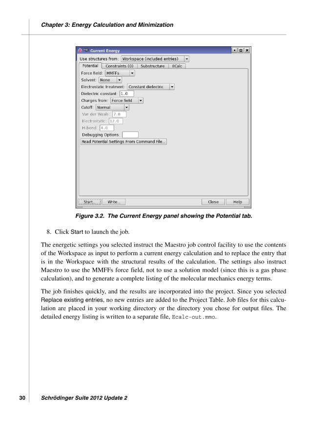
5. In the Constraints tab, clear any previously set constraints by clicking Reset All in boththe Constrain section and the Freeze section.
6. In the Substructure tab, clear any previously defined substructures and shells.
7. In the CSearch tab, select Large scale low-mode sampling from the Method option menu.
8. Enter 100 in the Maximum number of steps text box.
9. In the Mini tab, enter 1.00 in the Convergence threshold text box.
10. Click Start to open the Start dialog box.
11. Choose Append new entries as a new group from the Incorporate option menu.
12. Enter LLMOD in the Name text box.
After the job finishes, Maestro incorporates the structures into the Project Table. Depending onthe size of the structure, the computation may take some time to complete.
Schrödinger Suite 2012 Update 2

MacroModel Quick Start Guide
Chapter 5
Chapter 5: Other Calculations
MacroModel has a range of other capabilities than those already encountered. This chapterprovides exercises to illustrate some of these capabilities:
• Embrace—ligand binding to a receptor• Molecular dynamics• Energy profiles as a function of dihedral angles• Free energy calculations using MINTA• Partition coefficients between two solvents• Cluster analysis of structures
5.1 Ligand Binding using Embrace
Embrace is an automated routine that uses a collection of individual ligands, each pre-posi-tioned with respect to a given receptor. Embrace automatically performs energetic calculationson each complex formed from the receptor and the individual ligands. Embrace can work intwo modes—interaction mode and energy difference mode. In the first, the receptor and theligand are individually treated as separate sets, and only the energy components between setsare evaluated and recorded. The Embrace energy difference mode reports the minimizedenergy of both the individual ligand and receptor subtracted from the minimized energy of thecomplex. It is also possible to perform Embrace calculations using conformational searches.
Embrace calculations can be accelerated by using substructures with constraints applied toatom positions. The substructure need only include elements of the protein, not any ligands.This exercise demonstrates how to import a receptor and a group of ligands, and import asubstructure and run the calculations with constraints.
1. Import Embrace.mae from your working directory.
If you are not sure how to import a structure, use the directions in Section 2.1 on page 5.
This file contains a single protein and four pre-positioned ligands. Only the first structure,the receptor, is displayed in the Workspace.
2. In the Project Table, select all of the entries.
The structural input to an Embrace calculation must contain the receptor first, followedby the pre-positioned ligands. In Maestro, the receptor must be the first selected entry.
MacroModel 9.9 Quick Start Guide 51

Chapter 5: Other Calculations
52
Figure 5.1. The Embrace Minimization panel showing the Embrace tab.
3. Choose Applications → MacroModel → Embrace Minimization from the main window.
4. In the Potential tab, choose OPLS_2001 from the Force field option menu and chooseNone from the Solvent option menu.
5. In the Mini tab, enter 1000 in the Maximum Iterations text box.
6. Click the Embrace tab (see Figure 5.1).
7. Under Source of ligands, select Selected entries.
8. Under Receptor, select First selected entry.
9. Under Association energy mode, select Interaction energy mode.
10. Under Structures saved, select Complexes only.
11. In the Substructure tab, click Read .sbc file.
12. Select Embrace.sbc from your working directory.
The atoms in the structure are highlighted: white markers for the substructure, orangemarkers for shell 1, and purple markers for shell 2.
13. Click Start to open the Start dialog box.
Schrödinger Suite 2012 Update 2

Chapter 5: Other Calculations
14. Choose Append new entries from the Incorporate option menu.
15. Enter Embrace in the Name text box.
16. Click Start to launch the job.
This calculation may take 10 minutes. When the calculation is complete, the results are placedin a table at the end of the Embrace.log file and are incorporated into the Project Table.
5.2 Molecular Dynamics
Molecular dynamics calculations simulate molecular movement over time using Newton’sequations of motion. In this exercise, you will run an MC/SD dynamics calculation.
In the MC/SD simulation, an initial minimization is performed to ensure that the structure is ata minimum on the potential energy surface. Geometric structural parameters can be monitoredover the course of the dynamics simulation, and structures can be sampled during the simula-tion at constant intervals. Since MC/SD uses Monte Carlo methods, it is also necessary todefine the Monte Carlo parameters.
1. Import the structure in MCSD.mae from your working directory.
This structure has been minimized to a low gradient with MMFFs in the gas phase.
2. Choose Applications → MacroModel → MC/SD from the main window.
3. Choose Workspace (included entry) from the Use structures from option menu.
4. In the Potential tab, choose MMFFs from the Force field option menu and choose None
from the Solvent option menu.
5. In the Constraints tab, clear any previously set constraints by clicking the Reset All buttonin both the Constrain section and the Freeze section.
6. In the Substructure tab, click the Clear button in both the Atoms for substructure sectionand in the Shells section, to clear any previously defined substructures and shells.
7. In the Shells section, click Delete Shells until all shells are deleted.
8. In the Mini tab, enter 5000 in the Maximum iterations text box and enter 0.002 in the Con-
vergence threshold text box.
These parameters are required for the initial minimization.
MacroModel 9.9 Quick Start Guide 53
Chapter 5: Other Calculations
54
Figure 5.2. The MC/SD panel showing the MC/SD tab.
9. In the Monitor tab, enter 10 in the Number of structures to sample text box.
You can use the buttons in this tab if you want to conduct additional structuralmonitoring.
10. In the Dynamics tab, choose Stochastic dynamics from the Method option menu, andchoose Nothing from the SHAKE option menu.
SHAKE is not recommended for MC/SD simulations.
11. In the MCSD tab, click Perform Automatic Setup (see Figure 5.2).
To view the selected torsions, click Torsion Rotations in the middle of the panel.
12. Click Start to open the Start dialog box.
13. Choose Append new entries as a new group from the Incorporate option menu.
14. Enter MCSD in the Name text box.
15. Click Start to launch the job.
Schrödinger Suite 2012 Update 2

Chapter 5: Other Calculations
The ten sampled structures are incorporated into the Project Table at the completion of thecomputation. After incorporation, you can view the sample trajectory using Maestro’s ePlayer.The incorporated structures should already be selected in the Project Table. Click the Play
forward button on the ePlayer toolbar to view the trajectory in the Workspace.
For more information on the ePlayer, see Section 9.7 of the Maestro User Manual.
5.3 Creating Energy Profiles from Coordinate Scans
A contour diagram describing the molecular mechanics potential energy of a structure, relativeto the value of either one or two coordinates (distances, angles, or dihedrals), can be generatedwith MacroModel. These exercises demonstrate how to produce a contour diagram describingthe variation in energy of a molecule with respect to rotation of two dihedral angles.
5.3.1 Performing a Coordinate Scan Calculation
1. Import the structure in Ddrive.mae from your working directory.
2. Choose Applications → MacroModel → Coordinate Scan from the main window.
The Coordinate Scan panel opens.
3. Choose Workspace (included entry) from the Use structures from option menu.
4. In the Potential tab, choose MMFFs from the Force Field menu and choose None from theSolvent option menu.
5. In the Substructure tab, click the Clear button to clear any substructure.
6. Click Delete enough times to clear all shells.
7. From the Label atoms button menu on the main toolbar, choose Atom Number.
All atoms in the workspace are labeled with their corresponding atom number.
8. In the Scan tab of the Coordinate Scan panel, under Define coordinate to scan, chooseDihedral from the Coordinate type option menu.
9. Choose Atoms from the Pick menu (see Figure 5.3).
MacroModel 9.9 Quick Start Guide 55

Chapter 5: Other Calculations
56
Figure 5.3. The Coordinate Scan panel showing the Scan tab.
10. In the order listed, pick the atoms in the Workspace that define the two angles: 1, 14, 15,16, and 6, 25, 26, 27. (Use the middle mouse button to rotate the structure, if necessary.)
11. Click Start to open the Start dialog box.
12. Choose Do not incorporate from the Incorporate option menu.
13. Enter Ddrive in the Name text box.
14. Click Start to launch the job.
Two files are produced:
• Ddrive-out.grd contains the energetic results of the calculation• Ddrive-out.mae contains the structural output.
5.3.2 Analyzing the Results of the Coordinate Scan
You can create a contour diagram of Ddrive-out.grd in the Plot of Two-Coordinate Scan
panel (see Figure 5.4):
Schrödinger Suite 2012 Update 2

Chapter 5: Other Calculations
Figure 5.4. The Plot of Two-Coordinate Scan panel.
1. Choose Tools → Plot Coordinate Scan → Two Coordinates.
2. Click Open and select Ddrive-out.grd from your working directory.
3. Click Open.
The plot is displayed in the plotting area.
4. When you have finished examining the plot, close the Plot of Two-Coordinate Scan paneland choose Project → Close.
5.4 MINTA Prediction of Free Energy
MINTA is a powerful tool for estimating free energies from individual conformations orcollections of conformations. Many common methods for estimating the free energy of aconformation do so based on a single point in conformation space (i.e., the exact coordinatesprovided). A key feature of MINTA is that an integration is performed over the normal modesfor each conformation in order to accurately estimate the free energy of the local potentialminimum as a whole. As with other free energy methods, performing multiple MINTA calcula-tions and taking the appropriate differences among them can yield estimates of binding freeenergies. Note that while MINTA and MacroModel are tightly coupled, additional licensing isneeded to run MINTA.
MacroModel 9.9 Quick Start Guide 57
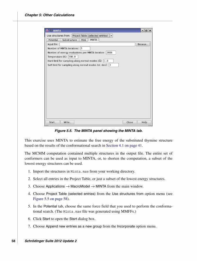
Chapter 5: Other Calculations
58
Figure 5.5. The MINTA panel showing the MINTA tab.
This exercise uses MINTA to estimate the free energy of the substituted thymine structurebased on the results of the conformational search in Section 4.1 on page 41.
The MCMM computation contained multiple structures in the output file. The entire set ofconformers can be used as input to MINTA, or, to shorten the computation, a subset of thelowest energy structures can be used.
1. Import the structures in Minta.mae from your working directory.
2. Select all entries in the Project Table, or just a subset of the lowest energy structures.
3. Choose Applications → MacroModel → MINTA from the main window.
4. Choose Project Table (selected entries) from the Use structures from option menu (seeFigure 5.5 on page 58).
5. In the Potential tab, choose the same force field that you used to perform the conforma-tional search. (The Minta.mae file was generated using MMFFs.)
6. Click Start to open the Start dialog box.
7. Choose Append new entries as a new group from the Incorporate option menu.
Schrödinger Suite 2012 Update 2

Chapter 5: Other Calculations
8. Enter Minta in the Name text box.
9. Click Start to launch the job.
The MINTA free energy and other information is written at the end of the .log file and isincluded as a set of properties in the Project Table.
5.5 Partition Coefficient Between Two Solvents
MacroModel can estimate the logarithm of the partition coefficient of a solute between twosolvents. The GB/SA parameterized solvents available are water, octanol, and chloroform.Multiple solutes can be used as input by selecting entries in the Project Table. The input struc-tures are minimized in each solvent, and the resulting difference in solvation energies is usedfor the logP calculation.
The octanol-water partition coefficient, logP(o/w), is often used as a measure of molecularhydrophobicity and other environmental parameters. In this exercise, you will run a logP(o/w)calculation from Maestro.
1. Import the structure in LogP.mae from your working directory.
2. Choose Applications → MacroModel → Multiple Minimization from the main window.
3. Choose Workspace (included entries) from the Use structures from option menu.
4. In the Potential tab, choose MMFFs from the Force field option menu and select Octanolfrom the Solvent option menu.
5. In the Mini tab, enter 5000 in the Maximum iterations text box and enter 0.02 in the Con-
vergence threshold text box.
6. In the Mult tab, select LogP estimation and choose Water from the Secondary solventoption menu (see Figure 5.6).
7. Click Start to open the Start dialog box.
8. Choose Append new entries as a new group from the Incorporate option menu.
9. Enter logP in the Name text box.
10. Click Start to launch the job.
The logP(o/w) value is written to the log file and is added to the output structure file as aproperty, which you can view in the Project Table.
MacroModel 9.9 Quick Start Guide 59

Chapter 5: Other Calculations
60
Figure 5.6. The Multiple Minimization panel showing LogP selected in the Mult tab.
Schrödinger Suite 2012 Update 2

MacroModel Quick Start Guide
Getting Help
Information about Schrödinger software is available in two main places:
• The docs folder (directory) of your software installation, which contains HTML andPDF documentation. Index pages are available in this folder.
• The Schrödinger web site, http://www.schrodinger.com/, particularly the Support Center,http://www.schrodinger.com/supportcenter, and the Knowledge Base, http://www.schro-dinger.com/kb.
Finding Information in Maestro
Maestro provides access to nearly all the information available on Schrödinger software.
To get information:
• Pause the pointer over a GUI feature (button, menu item, menu, ...). In the main window,information is displayed in the Auto-Help text box, which is located at the foot of themain window, or in a tooltip. In other panels, information is displayed in a tooltip.
If the tooltip does not appear within a second, check that Show tooltips is selected underGeneral → Appearance in the Preferences panel, which you can open with CTRL+, (,).Not all features have tooltips.
• Click the Help button in a panel or press F1 for information about a panel or the tab that isdisplayed in a panel. The help topic is displayed in your browser.
• Choose Help → Online Help or press CTRL+H (H) to open the default help topic in yourbrowser.
• When help is displayed in your browser, use the navigation links or search the help in theside bar.
• Choose Help → Manuals Index, to open a PDF file that has links to all the PDF docu-ments. Click a link to open the document.
• Choose Help → Search Manuals to search the manuals. The search tab in Adobe Readeropens, and you can search across all the PDF documents. You must have Adobe Readerinstalled to use this feature.
MacroModel 9.9 Quick Start Guide 61

Getting Help
62
For information on:
• Problems and solutions: choose Help → Knowledge Base or Help → Known Issues →product.
• Software updates: choose Maestro → Check for Updates.
• New software features: choose Help → New Features.
• Scripts available for download: choose Scripts → Update.
• Python scripting: choose Help → Python Module Overview.
• Utility programs: choose Help → About Utilities.
• Keyboard shortcuts: choose Help → Keyboard Shortcuts.
• Installation and licensing: see the Installation Guide.
• Running and managing jobs: see the Job Control Guide.
• Using Maestro: see the Maestro User Manual.
• Maestro commands: see the Maestro Command Reference Manual.
Contacting Technical Support
If you have questions that are not answered from any of the above sources, contact Schrödingerusing the information below.
E-mail: [email protected]: Schrödinger, 101 SW Main Street, Suite 1300, Portland, OR 97204Phone: (503) 299-1150Fax: (503) 299-4532WWW: http://www.schrodinger.comFTP: ftp://ftp.schrodinger.com
Generally, e-mail correspondence is best because you can send machine output, if necessary.When sending e-mail messages, please include the following information:
• All relevant user input and machine output• MacroModel purchaser (company, research institution, or individual)• Primary MacroModel user• Installation, licensing, and machine information as described below.
Schrödinger Suite 2012 Update 2

Getting Help
Gathering Information for Technical Support
This section describes how to gather the required machine, licensing, and installation informa-tion, and any other job-related or failure-related information, to send to technical support.
For general enquiries or problems:
1. Open the Diagnostics panel.
• Maestro: Help → Diagnostics • Windows: Start → All Programs → Schrodinger-2012 → Diagnostics • Mac: Applications → Schrodinger2012 → Diagnostics • Command line: $SCHRODINGER/diagnostics
2. When the diagnostics have run, click Technical Support.
A dialog box opens, with instructions. You can highlight and copy the name of the file.
3. Attach the file specified in the dialog box to your e-mail message.
If your job failed:
1. Open the Monitor panel in Maestro.
Use Applications → Monitor Jobs or Tasks → Monitor Jobs.
2. Select the failed job in the table, and click Postmortem.
The Postmortem panel opens.
3. If your data is not sensitive and you can send it, select Include structures and deselectAutomatically obfuscate path names.
4. Click Create.
An archive file is created in your working directory, and an information dialog box withthe name of the file opens. You can highlight and copy the name of the file.
5. Attach the file specified in the dialog box to your e-mail message.
6. Copy and paste any log messages from the window used to start Maestro (or the job) intothe email message,or attach them as a file.
• Windows: Right-click in the window and choose Select All, then press ENTER tocopy the text.
• Mac: Start the Console application (Applications → Utilities), filter on the applica-tion that you used to start the job (Maestro, BioLuminate, Elements), copy the text.
MacroModel 9.9 Quick Start Guide 63

Getting Help
64
If Maestro failed:
1. Open the Diagnostics panel.
• Windows: Start → All Programs → Schrodinger-2012 → Diagnostics • Mac: Applications → Schrodinger2012 → Diagnostics • Linux/command line: $SCHRODINGER/diagnostics
2. When the diagnostics have run, click Technical Support.
A dialog box opens, with instructions. You can highlight and copy the name of the file.
3. Attach the file specified in the dialog box to your e-mail message.
4. Attach the file maestro_error.txt to your e-mail message.
This file should be in the following location:
• Windows: %LOCALAPPDATA%\Schrodinger\appcrash (Choose Start → Run and paste this location into the Open text box.)
• Mac: Documents/Schrodinger • Linux: Maestro’s working directory specified in the dialog box (the location is
given in the terminal window).
5. On Windows, also attach the file maestro.EXE.dmp, which is in the same location asmaestro_error.txt.
Schrödinger Suite 2012 Update 2


120 West 45th Street 17th FloorNew York, NY 10036
101 SW Main StreetSuite 1300Portland, OR 97204
245 First StreetRiverview II, 18th FloorCambridge, MA 02142
8910 University Center LaneSuite 270San Diego, CA 92122
155 Gibbs StSuite 430Rockville, MD 20850-0353
Dynamostraße 13D-68165 MannheimGermany
Zeppelinstraße 73D-81669 MünchenGermany
Potsdamer Platz 11D-10785 BerlinGermany
Quatro HouseFrimley RoadCamberley GU16 7ERUnited Kingdom
8F Pacific Century Place1-11-1 MarunouchiChiyoda-ku, Tokyo 100-6208Japan
No. 102, 4th Block3rd Main Road, 3rd StageSharada ColonyBasaveshwaranagarBangalore 560079, India
SCHRÖDINGER ®