machine for industrial applications
TRANSCRIPT
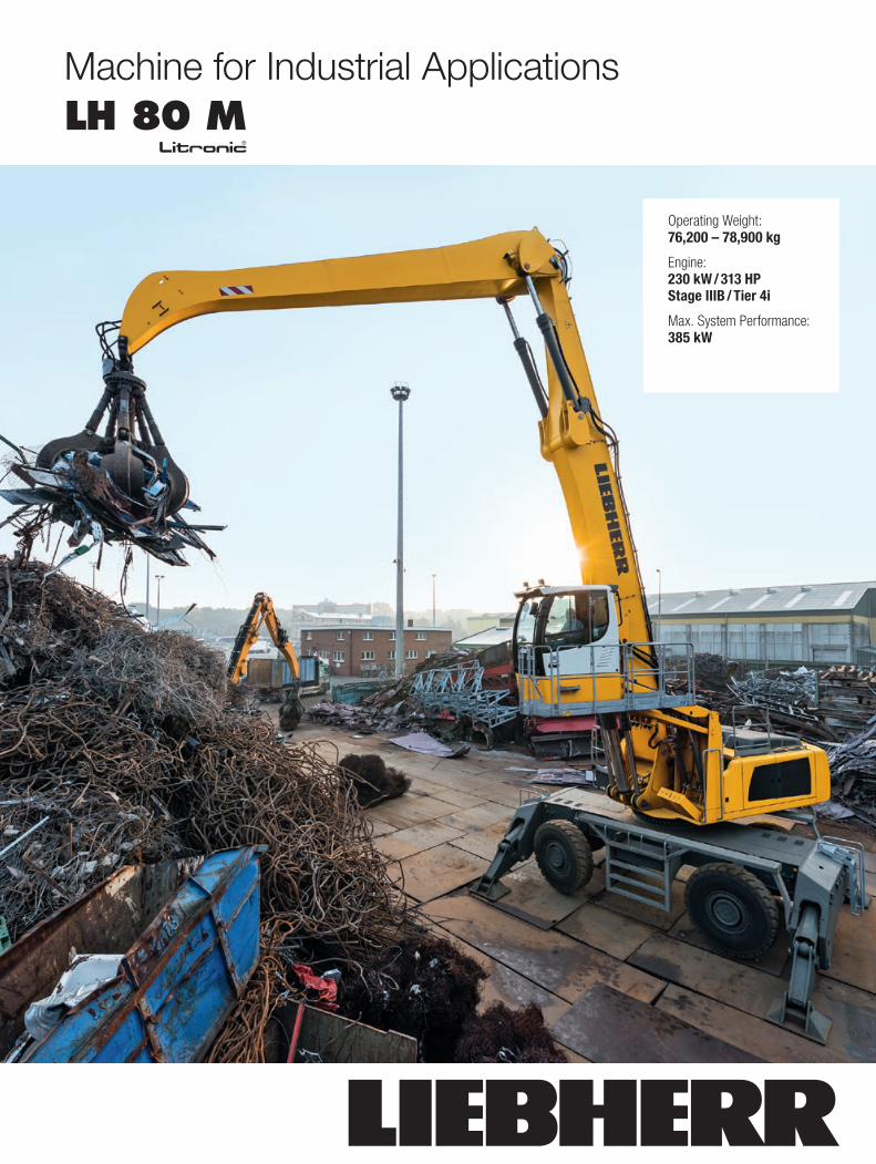
Machine for Industrial Applications LH 80 M
litronic̀
TB_LH80M_WF_.indd 1 26.05.14 14:05
Operating Weight: 76,200 – 78,900 kg
Engine: 230 kW / 313 HP Stage IIIB / Tier 4i
Max. System Performance: 385 kW
2 LH 80 M Litronic Machine for Industrial Applications
Technical Data
EngineRating per ISO 9249 230 kW (313 HP) at 1,700 RPMModel Liebherr D936 according to stage IIIB / Tier 4iType 6 cylinder in-line
Bore/Stroke 122/150 mmDisplacement 10.5 l
Engine operation 4-stroke diesel Common-Rail turbo-charged and after-cooled reduced emissions
Harmful emissions values in accordance with 97/68/EG stage IIIBEmission control Liebherr particle filterCooling water-cooled with integrated motor oil coolerAir cleaner dry-type air cleaner with pre-cleaner, primary and
safety elementsFuel tank 910 lEngine idling sensor controlledElectrical system
Voltage 24 VBatteries 2 x 170 Ah/12 VAlternator three phase current 28 V/100 A
Hydraulic ControlsPower distribution via control valves in single block with integrated safety
valvesServo circuit
Attachment and swing with hydraulic pilot control and proportional joystick levers
Travel electroproportional via foot pedalAdditional functions via switch or electroproportional foot pedalsOption proportional control, proportionally acting transmitters
on the joysticks for additional hydraulic functions
Hydraulic SystemHydraulic pump
for attachment and travel drive
two Liebherr variable flow, swashplate pumps (double construction)
Max. flow 2 x 350 l/min.Max. pressure 350 bar
Hydraulic pump regulation and control
electro-hydraulic with electronic engine speed sensing regulation, pressure compensation, flow compensa-tion, automatic oil flow optimizer
Hydraulic pumpfor swing drive reversible, variable flow, swashplate pump, closed-
loop circuitMax. flow 185 l/min.Max. pressure 380 bar
Hydraulic tank 390 lHydraulic system 910 lHydraulic oil filter 2 main return filters with integrated partial micro
filtration (5 μm)Hydraulic oil cooler cooling system, consisting of a cooling unit for water
and charge air and a 2nd cooler for hydraulic oil, each with an infinitely variable, thermostatically controlled fan drive system
MODE selection adjustment of engine and hydraulic performance via a mode pre-selector to match application, e.g. for especially economical and environmentally friendly operation or for maximum material handling and heavy-duty jobs
S (Sensitive) for precision work and lifting through very sensitive movements
E (ECO) for especially economical and environmentally friendly operation
P (Power) for maximum digging power and heavy duty jobsTool Control (Option) ten preadjustable pump flows and pressures for add
on tools
Swing DriveDrive Liebherr swashplate motor in a closed system with
integrated brake valveTransmission Liebherr planetary reduction gearSwing ring Liebherr, sealed single race ball bearing swing ring,
internal teethSwing speed 0 – 6.4 RPM steplessSwing torque 154 kNmBrake holding brake (spring applied – pressure released)Option pedal controlled positioning swing brake
LH 80 M Litronic Machine for Industrial Applications 3
Technical Data
Operator’s CabCab safety cab structure with individual windscreens or
featuring a slide-in subpart under the ceiling, work headlights integrated in the ceiling, a door with a side window (can be opened on both sides), large stowing and depositing possibilities, shock-absorbing suspen-sion, sounddamping insulating, tinted laminated safety glass, separate shades for the sunroof window and windscreen
Operator’s seat Standard air cushioned operator’s seat with headrest, lap belt, seat heater, manual weight adjustment, adjustable seat cushion inclination and length and mechanical lumbar vertebrae support
Operator’s seat Comfort (Option)
in addition to operator’s seat standard: lockable hori-zontal suspension, automatic weight adjustment, adjustable suspension stiffness, pneumatic lumbar vertebrae support and passive seat climatisation with active coal
Operator’s seat Premium (Option)
in addition to operator’s seat comfort: active electronic weight adjustment (automatic readjustment), pneu-matic low frequency suspension and active seat clima-tisation with active coal and ventilator
Control system joysticks with arm consoles and swivel seatOperation and displays large high-resolution operating unit, selfexplanatory,
colour display with touchscreen, video-compatible, numerous setting, control and monitoring options, e.g. air conditioning control, fuel consumption, machine and tool parameters
Air-conditioning automatic air-conditioning, recirculated air function, fast de-icing and demisting at the press of a button, air vents can be operated via a menu; recirculated air and fresh air filters can be easily replaced and are accessible from the outside; heating-cooling unit, designed for extreme outside temperatures, sensors for solar radiation, inside and outside temperatures
Noise emissionISO 6396 LpA (inside cab) = 71 dB(A)2000/14/EC LWA (surround noise) = 105 dB(A)
UndercarriageType torsion-resistant box design made from high-strength
steel plate, designed for the toughest requirementsDrive variable flow swashplate motor with automatic brake
valveTravel speed 0 – 10 km/h steplessDriving operation automotive driving using accelerator pedal, cruise
control function: storage of variable accelerator pedal positions
Axles 90 t drive axles; manual or automatic hydraulically controlled front axle oscillation lock
Service brake two circuit travel brake system with accumulator; maintenance-free, wet and backlash-free disc brake
Holding brake wet, maintenance-free multi disc brakesStabilization 4 point outriggers
AttachmentType high-strength steel plates at highlystressed points
for the toughest requirements. Complex and stable mountings of attachment and cylinders
Hydraulic cylinders Liebherr cylinders with special seal system. Shock absorption
Energy recovering cylinder Liebherr gas cylinder with special sealing and control system
Bearings sealed, low maintenance
Complete MachineLubrication central lubrication system for uppercarriage and
attachment, automatically
UppercarriageType slewing platform made from high-strength steel plate,
designed for the toughest requirements
4 LH 80 M Litronic Machine for Industrial Applications
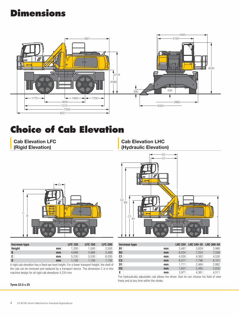
3951
1800
8221
1775 1700
752670753600
3724
2096
4483
4530
3193
535390
39806350
Dimensions
Choice of Cab ElevationCab Elevation LFC (Rigid Elevation)
Cab Elevation LHC (Hydraulic Elevation)
Increase type LFC 120 LFC 150 LFC 200Height mm 1,200 1,500 2,000B mm 4,688 4,988 5,488C mm 5,230 5,530 6,030D mm 1,156 1,156 1,156
A rigid cab elevation has a fixed eye level height. For a lower transport height, the shell of the cab can be removed and replaced by a transport device. The dimension C is in this machine design for all rigid cab elevations 4,334 mm.
Tyres 23.5 x 25
Increase type LHC 255 LHC 340-35 LHC 360-50B1 mm 3,487 3,839 3,988B2 mm 6,034 7,254 7,558C1 mm 4,030 4,382 4,530C2 mm 6,577 7,796 8,101D1 mm 1,711 2,484 2,882D2 mm 1,837 2,485 3,032E mm 3,971 4,361 4,511
The hydraulically adjustable cab allows the driver, that he can choose his field of view freely and at any time within the stroke.
B
D
H0624
C
B1C1
B2C2
E
D1D2
LH 80 M Litronic Machine for Industrial Applications 5
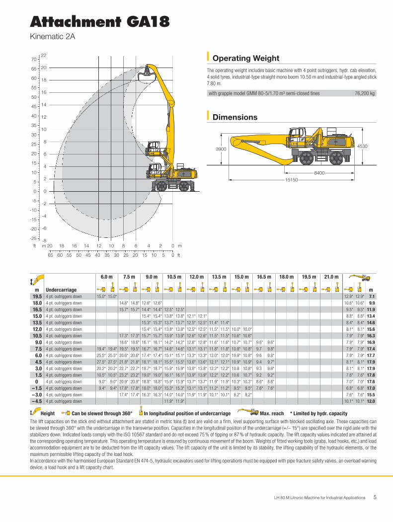
Attachment GA18Kinematic 2A
Dimensions
Operating WeightThe operating weight includes basic machine with 4 point outriggers, hydr. cab elevation, 4 solid tyres, industrial-type straight mono boom 10.50 m and industrial-type angled stick 7.80 m.
with grapple model GMM 80-5/1.70 m3 semi-closed tines 76,200 kg
8400
15150
4530
H0672
3900
30
55
60
65
70
50
45
40
35
25
20
15
10
5
0
-5
-10
-15
-20
-25
8
10
12
14
16
18
20
22 H0671
35404550556065 30 25 20 15 10 5 0
1214161820 10 8 6 4 2 0
6
4
2
0
-2
-4
-6
-8mft m
ft
m
Undercarriage
6.0 m 7.5 m 9.0 m 10.5 m 12.0 m 13.5 m 15.0 m 16.5 m 18.0 m 19.5 m 21.0 m
m19.5 4 pt. outriggers down 15.0* 15.0* 12.9* 12.9* 7.118.0 4 pt. outriggers down 14.8* 14.8* 12.6* 12.6* 10.6* 10.6* 9.916.5 4 pt. outriggers down 15.7* 15.7* 14.4* 14.4* 12.5* 12.5* 9.5* 9.5* 11.915.0 4 pt. outriggers down 15.4* 15.4* 13.8* 13.8* 12.1* 12.1* 8.8* 8.8* 13.413.5 4 pt. outriggers down 15.3* 15.3* 13.7* 13.7* 12.5* 12.5* 11.4* 11.4* 8.4* 8.4* 14.612.0 4 pt. outriggers down 15.4* 15.4* 13.8* 13.8* 12.5* 12.5* 11.5* 11.5* 10.0* 10.0* 8.1* 8.1* 15.610.5 4 pt. outriggers down 17.3* 17.3* 15.7* 15.7* 13.9* 13.9* 12.6* 12.6* 11.5* 11.5* 10.6* 10.6* 7.9* 7.9* 16.3
9.0 4 pt. outriggers down 18.6* 18.6* 16.1* 16.1* 14.2* 14.2* 12.8* 12.8* 11.6* 11.6* 10.7* 10.7* 9.6* 9.6* 7.9* 7.9* 16.97.5 4 pt. outriggers down 19.4* 19.4* 19.5* 19.5* 16.7* 16.7* 14.6* 14.6* 13.1* 13.1* 11.8* 11.8* 10.8* 10.8* 9.7 9.8* 7.9* 7.9* 17.46.0 4 pt. outriggers down 25.5* 25.5* 20.6* 20.6* 17.4* 17.4* 15.1* 15.1* 13.3* 13.3* 12.0* 12.0* 10.8* 10.8* 9.6 9.8* 7.9* 7.9* 17.74.5 4 pt. outriggers down 27.5* 27.5* 21.8* 21.8* 18.1* 18.1* 15.5* 15.5* 13.6* 13.6* 12.1* 12.1* 10.9* 10.9* 9.4 9.7* 8.1* 8.1* 17.93.0 4 pt. outriggers down 20.2* 20.2* 22.7* 22.7* 18.7* 18.7* 15.9* 15.9* 13.8* 13.8* 12.2* 12.2* 10.8 10.8* 9.3 9.6* 8.1* 8.1* 17.91.5 4 pt. outriggers down 10.5* 10.5* 23.2* 23.2* 19.0* 19.0* 16.1* 16.1* 13.9* 13.9* 12.2* 12.2* 10.6 10.7* 9.2 9.2* 7.6* 7.6* 17.80 4 pt. outriggers down 9.0* 9.0* 20.9* 20.9* 18.8* 18.8* 15.9* 15.9* 13.7* 13.7* 11.9* 11.9* 10.3* 10.3* 8.6* 8.6* 7.0* 7.0* 17.6
– 1.5 4 pt. outriggers down 9.4* 9.4* 17.8* 17.8* 18.0* 18.0* 15.3* 15.3* 13.1* 13.1* 11.2* 11.2* 9.5* 9.5* 7.6* 7.6* 6.8* 6.8* 17.0– 3.0 4 pt. outriggers down 17.4* 17.4* 16.3* 16.3* 14.0* 14.0* 11.9* 11.9* 10.1* 10.1* 8.2* 8.2* 7.6* 7.6* 15.5– 4.5 4 pt. outriggers down 11.9* 11.9* 10.1* 10.1* 12.0
Height Can be slewed through 360° In longitudinal position of undercarriage Max. reach * Limited by hydr. capacityThe lift capacities on the stick end without attachment are stated in metric tons (t) and are valid on a firm, level supporting surface with blocked oscillating axle. These capacities can be slewed through 360° with the undercarriage in the transverse position. Capacities in the longitudinal position of the undercarriage (+/– 15°) are specified over the rigid axle with the stabilizers down. Indicated loads comply with the ISO 10567 standard and do not exceed 75 % of tipping or 87 % of hydraulic capacity. The lift capacity values indicated are attained at the corresponding operating temperature. This operating temperature is ensured by continuous movement of the boom. Weights of fitted working tools (grabs, load hooks, etc.) and load accommodation equipment are to be deducted from the lift capacity values. The lift capacity of the unit is limited by its stability, the lifting capability of the hydraulic elements, or the maximum permissible lifting capacity of the load hook.In accordance with the harmonised European Standard EN 474-5, hydraulic excavators used for lifting operations must be equipped with pipe fracture safety valves, an overload warning device, a load hook and a lift capacity chart.
6 LH 80 M Litronic Machine for Industrial Applications
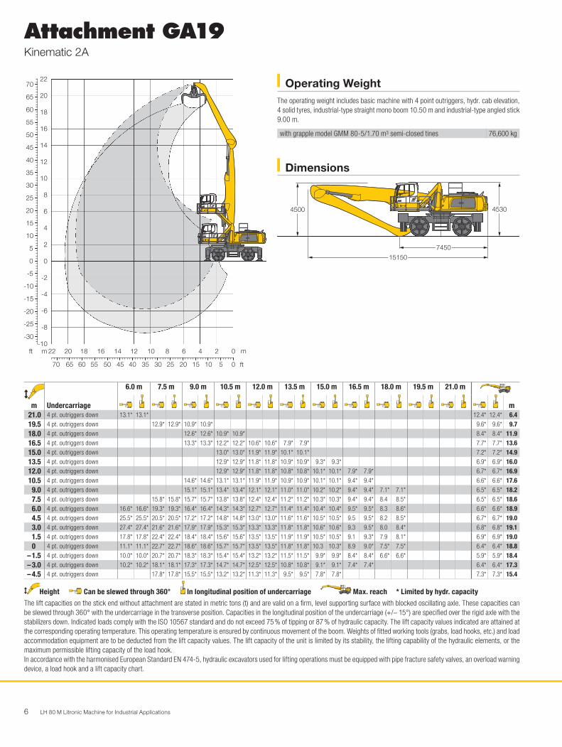
Attachment GA19Kinematic 2A
Dimensions
Operating WeightThe operating weight includes basic machine with 4 point outriggers, hydr. cab elevation, 4 solid tyres, industrial-type straight mono boom 10.50 m and industrial-type angled stick 9.00 m.
with grapple model GMM 80-5/1.70 m3 semi-closed tines 76,600 kg
7450
15150
4530
H0670
4500
m
Undercarriage
6.0 m 7.5 m 9.0 m 10.5 m 12.0 m 13.5 m 15.0 m 16.5 m 18.0 m 19.5 m 21.0 m
m21.0 4 pt. outriggers down 13.1* 13.1* 12.4* 12.4* 6.419.5 4 pt. outriggers down 12.9* 12.9* 10.9* 10.9* 9.6* 9.6* 9.718.0 4 pt. outriggers down 12.6* 12.6* 10.9* 10.9* 8.4* 8.4* 11.916.5 4 pt. outriggers down 13.3* 13.3* 12.2* 12.2* 10.6* 10.6* 7.9* 7.9* 7.7* 7.7* 13.615.0 4 pt. outriggers down 13.0* 13.0* 11.9* 11.9* 10.1* 10.1* 7.2* 7.2* 14.913.5 4 pt. outriggers down 12.9* 12.9* 11.8* 11.8* 10.9* 10.9* 9.3* 9.3* 6.9* 6.9* 16.012.0 4 pt. outriggers down 12.9* 12.9* 11.8* 11.8* 10.8* 10.8* 10.1* 10.1* 7.9* 7.9* 6.7* 6.7* 16.910.5 4 pt. outriggers down 14.6* 14.6* 13.1* 13.1* 11.9* 11.9* 10.9* 10.9* 10.1* 10.1* 9.4* 9.4* 6.6* 6.6* 17.6
9.0 4 pt. outriggers down 15.1* 15.1* 13.4* 13.4* 12.1* 12.1* 11.0* 11.0* 10.2* 10.2* 9.4* 9.4* 7.1* 7.1* 6.5* 6.5* 18.27.5 4 pt. outriggers down 15.8* 15.8* 15.7* 15.7* 13.8* 13.8* 12.4* 12.4* 11.2* 11.2* 10.3* 10.3* 9.4* 9.4* 8.4 8.5* 6.5* 6.5* 18.66.0 4 pt. outriggers down 16.6* 16.6* 19.3* 19.3* 16.4* 16.4* 14.3* 14.3* 12.7* 12.7* 11.4* 11.4* 10.4* 10.4* 9.5* 9.5* 8.3 8.6* 6.6* 6.6* 18.94.5 4 pt. outriggers down 25.5* 25.5* 20.5* 20.5* 17.2* 17.2* 14.8* 14.8* 13.0* 13.0* 11.6* 11.6* 10.5* 10.5* 9.5 9.5* 8.2 8.5* 6.7* 6.7* 19.03.0 4 pt. outriggers down 27.4* 27.4* 21.6* 21.6* 17.9* 17.9* 15.3* 15.3* 13.3* 13.3* 11.8* 11.8* 10.6* 10.6* 9.3 9.5* 8.0 8.4* 6.8* 6.8* 19.11.5 4 pt. outriggers down 17.8* 17.8* 22.4* 22.4* 18.4* 18.4* 15.6* 15.6* 13.5* 13.5* 11.9* 11.9* 10.5* 10.5* 9.1 9.3* 7.9 8.1* 6.9* 6.9* 19.00 4 pt. outriggers down 11.1* 11.1* 22.7* 22.7* 18.6* 18.6* 15.7* 15.7* 13.5* 13.5* 11.8* 11.8* 10.3 10.3* 8.9 9.0* 7.5* 7.5* 6.4* 6.4* 18.8
– 1.5 4 pt. outriggers down 10.0* 10.0* 20.7* 20.7* 18.3* 18.3* 15.4* 15.4* 13.2* 13.2* 11.5* 11.5* 9.9* 9.9* 8.4* 8.4* 6.6* 6.6* 5.9* 5.9* 18.4– 3.0 4 pt. outriggers down 10.2* 10.2* 18.1* 18.1* 17.3* 17.3* 14.7* 14.7* 12.5* 12.5* 10.8* 10.8* 9.1* 9.1* 7.4* 7.4* 6.4* 6.4* 17.3– 4.5 4 pt. outriggers down 17.8* 17.8* 15.5* 15.5* 13.2* 13.2* 11.3* 11.3* 9.5* 9.5* 7.8* 7.8* 7.3* 7.3* 15.4
Height Can be slewed through 360° In longitudinal position of undercarriage Max. reach * Limited by hydr. capacityThe lift capacities on the stick end without attachment are stated in metric tons (t) and are valid on a firm, level supporting surface with blocked oscillating axle. These capacities can be slewed through 360° with the undercarriage in the transverse position. Capacities in the longitudinal position of the undercarriage (+/– 15°) are specified over the rigid axle with the stabilizers down. Indicated loads comply with the ISO 10567 standard and do not exceed 75 % of tipping or 87 % of hydraulic capacity. The lift capacity values indicated are attained at the corresponding operating temperature. This operating temperature is ensured by continuous movement of the boom. Weights of fitted working tools (grabs, load hooks, etc.) and load accommodation equipment are to be deducted from the lift capacity values. The lift capacity of the unit is limited by its stability, the lifting capability of the hydraulic elements, or the maximum permissible lifting capacity of the load hook.In accordance with the harmonised European Standard EN 474-5, hydraulic excavators used for lifting operations must be equipped with pipe fracture safety valves, an overload warning device, a load hook and a lift capacity chart.
30
55
60
65
70
50
45
40
35
25
20
15
10
5
0
-5
-10
-15
-20
-25
-30
8
10
12
14
16
18
20
22H0669
3540455055606570 30 25 20 15 10 5 0
121416182022 10 8 6 4 2 0
6
4
2
0
-2
-4
-6
-8
-10mft m
ft

LH 80 M Litronic Machine for Industrial Applications 7
Attachment GA20Kinematic 2A
Dimensions
Operating WeightThe operating weight includes basic machine with 4 point outriggers, hydr. cab elevation, 4 solid tyres, industrial-type straight mono boom 11.50 m and industrial-type angled stick 9.00 m.
with grapple model GMM 80-5/1.70 m3 semi-closed tines 77,200 kg
8350
16150
4530
H0668
4300
m
Undercarriage
6.0 m 7.5 m 9.0 m 10.5 m 12.0 m 13.5 m 15.0 m 16.5 m 18.0 m 19.5 m 21.0 m
m21.0 4 pt. outriggers down 12.5* 12.5* 10.3* 10.3* 8.919.5 4 pt. outriggers down 12.3* 12.3* 10.5* 10.5* 8.8* 8.8* 11.518.0 4 pt. outriggers down 13.1* 13.1* 12.0* 12.0* 10.4* 10.4* 7.9* 7.9* 13.416.5 4 pt. outriggers down 12.8* 12.8* 11.6* 11.6* 10.1* 10.1* 7.4* 7.4* 14.915.0 4 pt. outriggers down 12.7* 12.7* 11.5* 11.5* 10.5* 10.5* 9.5* 9.5* 7.1* 7.1* 16.113.5 4 pt. outriggers down 12.7* 12.7* 11.5* 11.5* 10.4* 10.4* 9.6* 9.6* 8.5* 8.5* 6.8* 6.8* 17.212.0 4 pt. outriggers down 14.4* 14.4* 12.8* 12.8* 11.5* 11.5* 10.5* 10.5* 9.6* 9.6* 8.9* 8.9* 6.7* 6.7* 18.010.5 4 pt. outriggers down 14.8* 14.8* 13.0* 13.0* 11.7* 11.7* 10.6* 10.6* 9.6* 9.6* 8.9* 8.9* 8.2* 8.2* 6.6* 6.6* 18.6
9.0 4 pt. outriggers down 15.1* 15.1* 15.2* 15.2* 13.3* 13.3* 11.9* 11.9* 10.7* 10.7* 9.7* 9.7* 8.9* 8.9* 8.2* 8.2* 6.5* 6.5* 19.27.5 4 pt. outriggers down 15.0* 15.0* 17.5* 17.5* 15.7* 15.7* 13.7* 13.7* 12.1* 12.1* 10.8* 10.8* 9.8* 9.8* 9.0* 9.0* 8.2* 8.2* 6.8* 6.8* 6.5* 6.5* 19.66.0 4 pt. outriggers down 22.3* 22.3* 19.5* 19.5* 16.3* 16.3* 14.1* 14.1* 12.4* 12.4* 11.0* 11.0* 9.9* 9.9* 9.0* 9.0* 8.0 8.2* 6.9 7.3* 6.6* 6.6* 19.84.5 4 pt. outriggers down 25.9* 25.9* 20.5* 20.5* 16.9* 16.9* 14.4* 14.4* 12.6* 12.6* 11.2* 11.2* 10.0* 10.0* 9.0* 9.0* 7.9 8.1* 6.8 7.1* 6.5 6.7* 20.03.0 4 pt. outriggers down 15.7* 15.7* 21.2* 21.2* 17.4* 17.4* 14.8* 14.8* 12.8* 12.8* 11.3* 11.3* 10.0* 10.0* 8.9 9.0* 7.7 8.0* 6.7 6.9* 6.4* 6.4* 20.01.5 4 pt. outriggers down 7.7* 7.7* 21.6* 21.6* 17.7* 17.7* 14.9* 14.9* 12.9* 12.9* 11.3* 11.3* 10.0* 10.0* 8.7 8.9* 7.6 7.8* 6.5* 6.5* 6.0* 6.0* 20.00 4 pt. outriggers down 6.5* 6.5* 14.8* 14.8* 17.6* 17.6* 14.9* 14.9* 12.8* 12.8* 11.2* 11.2* 9.8* 9.8* 8.5 8.6* 7.4* 7.4* 5.9* 5.9* 5.5* 5.5* 19.8
– 1.5 4 pt. outriggers down 6.7* 6.7* 12.6* 12.6* 17.0* 17.0* 14.4* 14.4* 12.4* 12.4* 10.8* 10.8* 9.4* 9.4* 8.1* 8.1* 6.8* 6.8* 5.0* 5.0* 19.4– 3.0 4 pt. outriggers down 7.5* 7.5* 12.3* 12.3* 15.8* 15.8* 13.6* 13.6* 11.7* 11.7* 10.1* 10.1* 8.7* 8.7* 7.3* 7.3* 5.7* 5.7* 5.4* 5.4* 18.3– 4.5 4 pt. outriggers down 12.7* 12.7* 13.9* 13.9* 12.1* 12.1* 10.5* 10.5* 9.0* 9.0* 7.5* 7.5* 6.2* 6.2* 16.4
Height Can be slewed through 360° In longitudinal position of undercarriage Max. reach * Limited by hydr. capacityThe lift capacities on the stick end without attachment are stated in metric tons (t) and are valid on a firm, level supporting surface with blocked oscillating axle. These capacities can be slewed through 360° with the undercarriage in the transverse position. Capacities in the longitudinal position of the undercarriage (+/– 15°) are specified over the rigid axle with the stabilizers down. Indicated loads comply with the ISO 10567 standard and do not exceed 75 % of tipping or 87 % of hydraulic capacity. The lift capacity values indicated are attained at the corresponding operating temperature. This operating temperature is ensured by continuous movement of the boom. Weights of fitted working tools (grabs, load hooks, etc.) and load accommodation equipment are to be deducted from the lift capacity values. The lift capacity of the unit is limited by its stability, the lifting capability of the hydraulic elements, or the maximum permissible lifting capacity of the load hook.In accordance with the harmonised European Standard EN 474-5, hydraulic excavators used for lifting operations must be equipped with pipe fracture safety valves, an overload warning device, a load hook and a lift capacity chart.
30
55
60
65
70
75
50
45
40
35
25
20
15
10
5
0
-5
-10
-15
-20
-25
-30
8
10
12
14
16
18
20
22
24H0667
3540455055606570 30 25 20 15 10 5 0
121416182022 10 8 6 4 2 0
6
4
2
0
-2
-4
-6
-8
-10mft m
ft
8 LH 80 M Litronic Machine for Industrial Applications
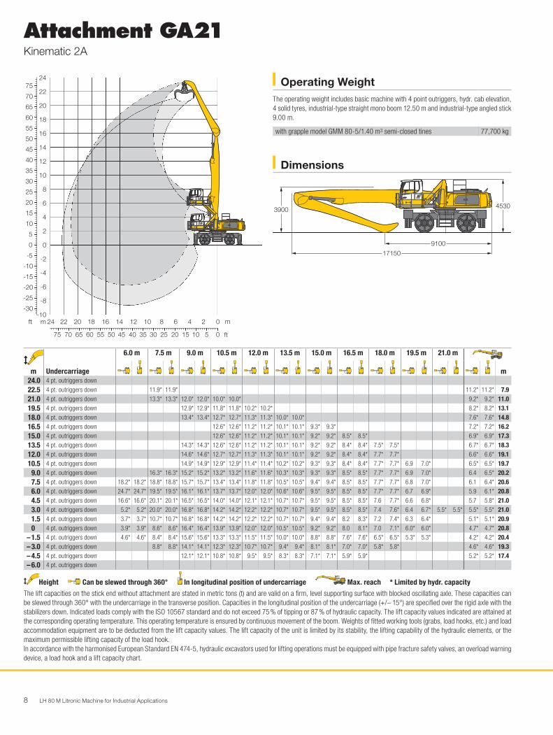
Attachment GA21Kinematic 2A
Dimensions
Operating WeightThe operating weight includes basic machine with 4 point outriggers, hydr. cab elevation, 4 solid tyres, industrial-type straight mono boom 12.50 m and industrial-type angled stick 9.00 m.
with grapple model GMM 80-5/1.40 m3 semi-closed tines 77,700 kg
9100
17150
4530
H0624
3900
m
Undercarriage
6.0 m 7.5 m 9.0 m 10.5 m 12.0 m 13.5 m 15.0 m 16.5 m 18.0 m 19.5 m 21.0 m
m24.0 4 pt. outriggers down22.5 4 pt. outriggers down 11.9* 11.9* 11.2* 11.2* 7.921.0 4 pt. outriggers down 13.3* 13.3* 12.0* 12.0* 10.0* 10.0* 9.2* 9.2* 11.019.5 4 pt. outriggers down 12.9* 12.9* 11.8* 11.8* 10.2* 10.2* 8.2* 8.2* 13.118.0 4 pt. outriggers down 13.4* 13.4* 12.7* 12.7* 11.3* 11.3* 10.0* 10.0* 7.6* 7.6* 14.816.5 4 pt. outriggers down 12.6* 12.6* 11.2* 11.2* 10.1* 10.1* 9.3* 9.3* 7.2* 7.2* 16.215.0 4 pt. outriggers down 12.6* 12.6* 11.2* 11.2* 10.1* 10.1* 9.2* 9.2* 8.5* 8.5* 6.9* 6.9* 17.313.5 4 pt. outriggers down 14.3* 14.3* 12.6* 12.6* 11.2* 11.2* 10.1* 10.1* 9.2* 9.2* 8.4* 8.4* 7.5* 7.5* 6.7* 6.7* 18.312.0 4 pt. outriggers down 14.6* 14.6* 12.7* 12.7* 11.3* 11.3* 10.1* 10.1* 9.2* 9.2* 8.4* 8.4* 7.7* 7.7* 6.6* 6.6* 19.110.5 4 pt. outriggers down 14.9* 14.9* 12.9* 12.9* 11.4* 11.4* 10.2* 10.2* 9.3* 9.3* 8.4* 8.4* 7.7* 7.7* 6.9 7.0* 6.5* 6.5* 19.7
9.0 4 pt. outriggers down 16.3* 16.3* 15.2* 15.2* 13.2* 13.2* 11.6* 11.6* 10.3* 10.3* 9.3* 9.3* 8.5* 8.5* 7.7* 7.7* 6.9 7.0* 6.4 6.5* 20.27.5 4 pt. outriggers down 18.2* 18.2* 18.8* 18.8* 15.7* 15.7* 13.4* 13.4* 11.8* 11.8* 10.5* 10.5* 9.4* 9.4* 8.5* 8.5* 7.7* 7.7* 6.8 7.0* 6.1 6.4* 20.66.0 4 pt. outriggers down 24.7* 24.7* 19.5* 19.5* 16.1* 16.1* 13.7* 13.7* 12.0* 12.0* 10.6* 10.6* 9.5* 9.5* 8.5* 8.5* 7.7* 7.7* 6.7 6.9* 5.9 6.1* 20.84.5 4 pt. outriggers down 16.6* 16.6* 20.1* 20.1* 16.5* 16.5* 14.0* 14.0* 12.1* 12.1* 10.7* 10.7* 9.5* 9.5* 8.5* 8.5* 7.6 7.7* 6.6 6.8* 5.7 5.8* 21.03.0 4 pt. outriggers down 5.2* 5.2* 20.0* 20.0* 16.8* 16.8* 14.2* 14.2* 12.2* 12.2* 10.7* 10.7* 9.5* 9.5* 8.5* 8.5* 7.4 7.6* 6.4 6.7* 5.5* 5.5* 5.5* 5.5* 21.01.5 4 pt. outriggers down 3.7* 3.7* 10.7* 10.7* 16.8* 16.8* 14.2* 14.2* 12.2* 12.2* 10.7* 10.7* 9.4* 9.4* 8.2 8.3* 7.2 7.4* 6.3 6.4* 5.1* 5.1* 20.90 4 pt. outriggers down 3.9* 3.9* 8.6* 8.6* 16.4* 16.4* 13.9* 13.9* 12.0* 12.0* 10.5* 10.5* 9.2* 9.2* 8.0 8.1* 7.0 7.1* 6.0* 6.0* 4.7* 4.7* 20.8
– 1.5 4 pt. outriggers down 4.6* 4.6* 8.4* 8.4* 15.6* 15.6* 13.3* 13.3* 11.5* 11.5* 10.0* 10.0* 8.8* 8.8* 7.6* 7.6* 6.5* 6.5* 5.3* 5.3* 4.2* 4.2* 20.4– 3.0 4 pt. outriggers down 8.8* 8.8* 14.1* 14.1* 12.3* 12.3* 10.7* 10.7* 9.4* 9.4* 8.1* 8.1* 7.0* 7.0* 5.8* 5.8* 4.6* 4.6* 19.3– 4.5 4 pt. outriggers down 12.1* 12.1* 10.8* 10.8* 9.5* 9.5* 8.3* 8.3* 7.1* 7.1* 5.9* 5.9* 5.2* 5.2* 17.4– 6.0 4 pt. outriggers down
Height Can be slewed through 360° In longitudinal position of undercarriage Max. reach * Limited by hydr. capacityThe lift capacities on the stick end without attachment are stated in metric tons (t) and are valid on a firm, level supporting surface with blocked oscillating axle. These capacities can be slewed through 360° with the undercarriage in the transverse position. Capacities in the longitudinal position of the undercarriage (+/– 15°) are specified over the rigid axle with the stabilizers down. Indicated loads comply with the ISO 10567 standard and do not exceed 75 % of tipping or 87 % of hydraulic capacity. The lift capacity values indicated are attained at the corresponding operating temperature. This operating temperature is ensured by continuous movement of the boom. Weights of fitted working tools (grabs, load hooks, etc.) and load accommodation equipment are to be deducted from the lift capacity values. The lift capacity of the unit is limited by its stability, the lifting capability of the hydraulic elements, or the maximum permissible lifting capacity of the load hook.In accordance with the harmonised European Standard EN 474-5, hydraulic excavators used for lifting operations must be equipped with pipe fracture safety valves, an overload warning device, a load hook and a lift capacity chart.
30
55
60
65
70
75
50
45
40
35
25
20
15
10
5
0
-5
-10
-15
-20
-25
-30
8
10
12
14
16
18
20
22
24H0625
354045505560657075 30 25 20 15 10 5 0
12141618202224 10 8 6 4 2 0
6
4
2
0
-2
-4
-6
-8
-10mft m
ft
LH 80 M Litronic Machine for Industrial Applications 9
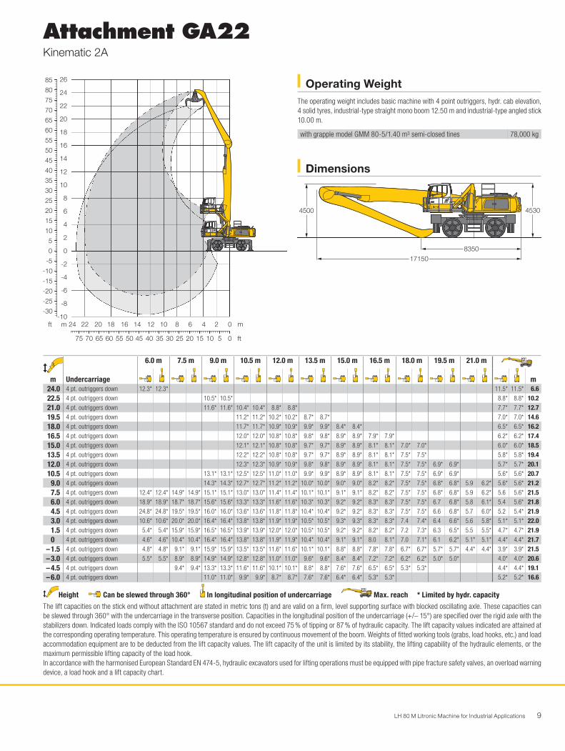
Attachment GA22Kinematic 2A
Dimensions
Operating WeightThe operating weight includes basic machine with 4 point outriggers, hydr. cab elevation, 4 solid tyres, industrial-type straight mono boom 12.50 m and industrial-type angled stick 10.00 m.
with grapple model GMM 80-5/1.40 m3 semi-closed tines 78,000 kg
30
55
60
65
70
75
80
85
50
45
40
35
25
20
15
10
5
0
-5
-10
-15
-20
-25
-30
8
10
12
14
16
18
20
22
24
26 H0673
354045505560657075 30 25 20 15 10 5 0
12141618202224 10 8 6 4 2 0
6
4
2
0
-2
-4
-6
-8
-10mft m
ft
8350
17150
4530
H0674
4500
m
Undercarriage
6.0 m 7.5 m 9.0 m 10.5 m 12.0 m 13.5 m 15.0 m 16.5 m 18.0 m 19.5 m 21.0 m
m24.0 4 pt. outriggers down 12.3* 12.3* 11.5* 11.5* 6.622.5 4 pt. outriggers down 10.5* 10.5* 8.8* 8.8* 10.221.0 4 pt. outriggers down 11.6* 11.6* 10.4* 10.4* 8.8* 8.8* 7.7* 7.7* 12.719.5 4 pt. outriggers down 11.2* 11.2* 10.2* 10.2* 8.7* 8.7* 7.0* 7.0* 14.618.0 4 pt. outriggers down 11.7* 11.7* 10.9* 10.9* 9.9* 9.9* 8.4* 8.4* 6.5* 6.5* 16.216.5 4 pt. outriggers down 12.0* 12.0* 10.8* 10.8* 9.8* 9.8* 8.9* 8.9* 7.9* 7.9* 6.2* 6.2* 17.415.0 4 pt. outriggers down 12.1* 12.1* 10.8* 10.8* 9.7* 9.7* 8.9* 8.9* 8.1* 8.1* 7.0* 7.0* 6.0* 6.0* 18.513.5 4 pt. outriggers down 12.2* 12.2* 10.8* 10.8* 9.7* 9.7* 8.9* 8.9* 8.1* 8.1* 7.5* 7.5* 5.8* 5.8* 19.412.0 4 pt. outriggers down 12.3* 12.3* 10.9* 10.9* 9.8* 9.8* 8.9* 8.9* 8.1* 8.1* 7.5* 7.5* 6.9* 6.9* 5.7* 5.7* 20.110.5 4 pt. outriggers down 13.1* 13.1* 12.5* 12.5* 11.0* 11.0* 9.9* 9.9* 8.9* 8.9* 8.1* 8.1* 7.5* 7.5* 6.9* 6.9* 5.6* 5.6* 20.7
9.0 4 pt. outriggers down 14.3* 14.3* 12.7* 12.7* 11.2* 11.2* 10.0* 10.0* 9.0* 9.0* 8.2* 8.2* 7.5* 7.5* 6.8* 6.8* 5.9 6.2* 5.6* 5.6* 21.27.5 4 pt. outriggers down 12.4* 12.4* 14.9* 14.9* 15.1* 15.1* 13.0* 13.0* 11.4* 11.4* 10.1* 10.1* 9.1* 9.1* 8.2* 8.2* 7.5* 7.5* 6.8* 6.8* 5.9 6.2* 5.6 5.6* 21.56.0 4 pt. outriggers down 18.9* 18.9* 18.7* 18.7* 15.6* 15.6* 13.3* 13.3* 11.6* 11.6* 10.3* 10.3* 9.2* 9.2* 8.3* 8.3* 7.5* 7.5* 6.7 6.8* 5.8 6.1* 5.4 5.6* 21.84.5 4 pt. outriggers down 24.8* 24.8* 19.5* 19.5* 16.0* 16.0* 13.6* 13.6* 11.8* 11.8* 10.4* 10.4* 9.2* 9.2* 8.3* 8.3* 7.5* 7.5* 6.6 6.8* 5.7 6.0* 5.2 5.4* 21.93.0 4 pt. outriggers down 10.6* 10.6* 20.0* 20.0* 16.4* 16.4* 13.8* 13.8* 11.9* 11.9* 10.5* 10.5* 9.3* 9.3* 8.3* 8.3* 7.4 7.4* 6.4 6.6* 5.6 5.8* 5.1* 5.1* 22.01.5 4 pt. outriggers down 5.4* 5.4* 15.9* 15.9* 16.5* 16.5* 13.9* 13.9* 12.0* 12.0* 10.5* 10.5* 9.2* 9.2* 8.2* 8.2* 7.2 7.3* 6.3 6.5* 5.5 5.5* 4.7* 4.7* 21.90 4 pt. outriggers down 4.6* 4.6* 10.4* 10.4* 16.4* 16.4* 13.8* 13.8* 11.9* 11.9* 10.4* 10.4* 9.1* 9.1* 8.0 8.1* 7.0 7.1* 6.1 6.2* 5.1* 5.1* 4.4* 4.4* 21.7
– 1.5 4 pt. outriggers down 4.8* 4.8* 9.1* 9.1* 15.9* 15.9* 13.5* 13.5* 11.6* 11.6* 10.1* 10.1* 8.8* 8.8* 7.8* 7.8* 6.7* 6.7* 5.7* 5.7* 4.4* 4.4* 3.9* 3.9* 21.5– 3.0 4 pt. outriggers down 5.5* 5.5* 8.9* 8.9* 14.9* 14.9* 12.8* 12.8* 11.0* 11.0* 9.6* 9.6* 8.4* 8.4* 7.2* 7.2* 6.2* 6.2* 5.0* 5.0* 4.0* 4.0* 20.6– 4.5 4 pt. outriggers down 9.4* 9.4* 13.3* 13.3* 11.6* 11.6* 10.1* 10.1* 8.8* 8.8* 7.6* 7.6* 6.5* 6.5* 5.3* 5.3* 4.4* 4.4* 19.1– 6.0 4 pt. outriggers down 11.0* 11.0* 9.9* 9.9* 8.7* 8.7* 7.6* 7.6* 6.4* 6.4* 5.3* 5.3* 5.2* 5.2* 16.6
Height Can be slewed through 360° In longitudinal position of undercarriage Max. reach * Limited by hydr. capacityThe lift capacities on the stick end without attachment are stated in metric tons (t) and are valid on a firm, level supporting surface with blocked oscillating axle. These capacities can be slewed through 360° with the undercarriage in the transverse position. Capacities in the longitudinal position of the undercarriage (+/– 15°) are specified over the rigid axle with the stabilizers down. Indicated loads comply with the ISO 10567 standard and do not exceed 75 % of tipping or 87 % of hydraulic capacity. The lift capacity values indicated are attained at the corresponding operating temperature. This operating temperature is ensured by continuous movement of the boom. Weights of fitted working tools (grabs, load hooks, etc.) and load accommodation equipment are to be deducted from the lift capacity values. The lift capacity of the unit is limited by its stability, the lifting capability of the hydraulic elements, or the maximum permissible lifting capacity of the load hook.In accordance with the harmonised European Standard EN 474-5, hydraulic excavators used for lifting operations must be equipped with pipe fracture safety valves, an overload warning device, a load hook and a lift capacity chart.
10 LH 80 M Litronic Machine for Industrial Applications
Attachment AG19Kinematic 2D
Dimensions
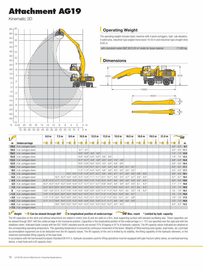
Operating WeightThe operating weight includes basic machine with 4 point outriggers, hydr. cab elevation, 4 solid tyres, industrial-type angled mono boom 10.50 m and industrial-type straight stick 9.00 m.
with clamshell model GMZ 80/3.00 m3 shells for loose material 77,000 kg
14950
4530
H0676
4300
9500
1250
1250
m
Undercarriage
6.0 m 7.5 m 9.0 m 10.5 m 12.0 m 13.5 m 15.0 m 16.5 m 18.0 m 19.5 m 21.0 m
m19.5 4 pt. outriggers down 9.2* 9.2* 8.718.0 4 pt. outriggers down 9.1* 9.1* 8.0* 8.0* 11.116.5 4 pt. outriggers down 10.9* 10.9* 9.0* 9.0* 7.4* 7.4* 12.915.0 4 pt. outriggers down 10.8* 10.8* 10.0* 10.0* 8.6* 8.6* 7.0* 7.0* 14.313.5 4 pt. outriggers down 10.7* 10.7* 9.9* 9.9* 9.3* 9.3* 7.8* 7.8* 6.8* 6.8* 15.412.0 4 pt. outriggers down 10.8* 10.8* 10.0* 10.0* 9.3* 9.3* 8.8* 8.8* 6.6* 6.6* 16.410.5 4 pt. outriggers down 11.0* 11.0* 10.1* 10.1* 9.4* 9.4* 8.9* 8.9* 8.1* 8.1* 6.5* 6.5* 17.1
9.0 4 pt. outriggers down 11.3* 11.3* 10.4* 10.4* 9.6* 9.6* 9.0* 9.0* 8.5* 8.5* 6.5* 6.5* 17.77.5 4 pt. outriggers down 13.2* 13.2* 11.8* 11.8* 10.7* 10.7* 9.8* 9.8* 9.1* 9.1* 8.6* 8.6* 6.9* 6.9* 6.6* 6.6* 18.16.0 4 pt. outriggers down 16.3* 16.3* 14.0* 14.0* 12.4* 12.4* 11.1* 11.1* 10.1* 10.1* 9.4* 9.4* 8.7* 8.7* 8.0* 8.0* 6.7* 6.7* 18.44.5 4 pt. outriggers down 21.9* 21.9* 17.7* 17.7* 15.0* 15.0* 13.0* 13.0* 11.6* 11.6* 10.5* 10.5* 9.6* 9.6* 8.9* 8.9* 8.3* 8.3* 6.9* 6.9* 18.63.0 4 pt. outriggers down 24.3* 24.3* 19.2* 19.2* 15.9* 15.9* 13.7* 13.7* 12.1* 12.1* 10.8* 10.8* 9.8* 9.8* 9.0* 9.0* 8.1 8.3* 7.1* 7.1* 18.61.5 4 pt. outriggers down 22.3* 22.3* 20.5* 20.5* 16.8* 16.8* 14.3* 14.3* 12.5* 12.5* 11.1* 11.1* 10.0* 10.0* 9.1* 9.1* 8.0 8.3* 7.4* 7.4* 18.50 4 pt. outriggers down 13.6* 13.6* 21.5* 21.5* 17.6* 17.6* 14.8* 14.8* 12.9* 12.9* 11.4* 11.4* 10.2* 10.2* 9.0 9.2* 7.8 8.2* 7.6 7.8* 18.3
– 1.5 4 pt. outriggers down 11.6* 11.6* 22.0* 22.0* 18.0* 18.0* 15.2* 15.2* 13.1* 13.1* 11.5* 11.5* 10.2 10.2* 8.8 9.1* 7.8 7.9* 18.0– 3.0 4 pt. outriggers down 11.4* 11.4* 19.3* 19.3* 18.0* 18.0* 15.2* 15.2* 13.1* 13.1* 11.5* 11.5* 10.0 10.1* 8.7 8.8* 7.8* 7.8* 17.5– 4.5 4 pt. outriggers down 11.7* 11.7* 18.4* 18.4* 17.5* 17.5* 14.9* 14.9* 12.8* 12.8* 11.1* 11.1* 9.6* 9.6* 8.0* 8.0* 7.5* 7.5* 16.9– 6.0 4 pt. outriggers down 18.6* 18.6* 16.4* 16.4* 14.0* 14.0* 12.0* 12.0* 10.2* 10.2* 8.5* 8.5* 8.3* 8.3* 15.2– 7.5 4 pt. outriggers down
Height Can be slewed through 360° In longitudinal position of undercarriage Max. reach * Limited by hydr. capacityThe lift capacities on the stick end without attachment are stated in metric tons (t) and are valid on a firm, level supporting surface with blocked oscillating axle. These capacities can be slewed through 360° with the undercarriage in the transverse position. Capacities in the longitudinal position of the undercarriage (+/– 15°) are specified over the rigid axle with the stabilizers down. Indicated loads comply with the ISO 10567 standard and do not exceed 75 % of tipping or 87 % of hydraulic capacity. The lift capacity values indicated are attained at the corresponding operating temperature. This operating temperature is ensured by continuous movement of the boom. Weights of fitted working tools (grabs, load hooks, etc.) and load accommodation equipment are to be deducted from the lift capacity values. The lift capacity of the unit is limited by its stability, the lifting capability of the hydraulic elements, or the maximum permissible lifting capacity of the load hook.In accordance with the harmonised European Standard EN 474-5, hydraulic excavators used for lifting operations must be equipped with pipe fracture safety valves, an overload warning device, a load hook and a lift capacity chart.
30
55
60
65
50
45
40
35
25
20
15
10
5
0
-5
-10
-15
-20
-25
-30
-35
8
10
12
14
16
18
20H0675
3540455055606570 30 25 20 15 10 5 0
121416182022 10 8 6 4 2 0
6
4
2
0
-2
-4
-6
-8
-10
-12mft m
ft
LH 80 M Litronic Machine for Industrial Applications 11
Attachment AG19Kinematic 2C
Dimensions
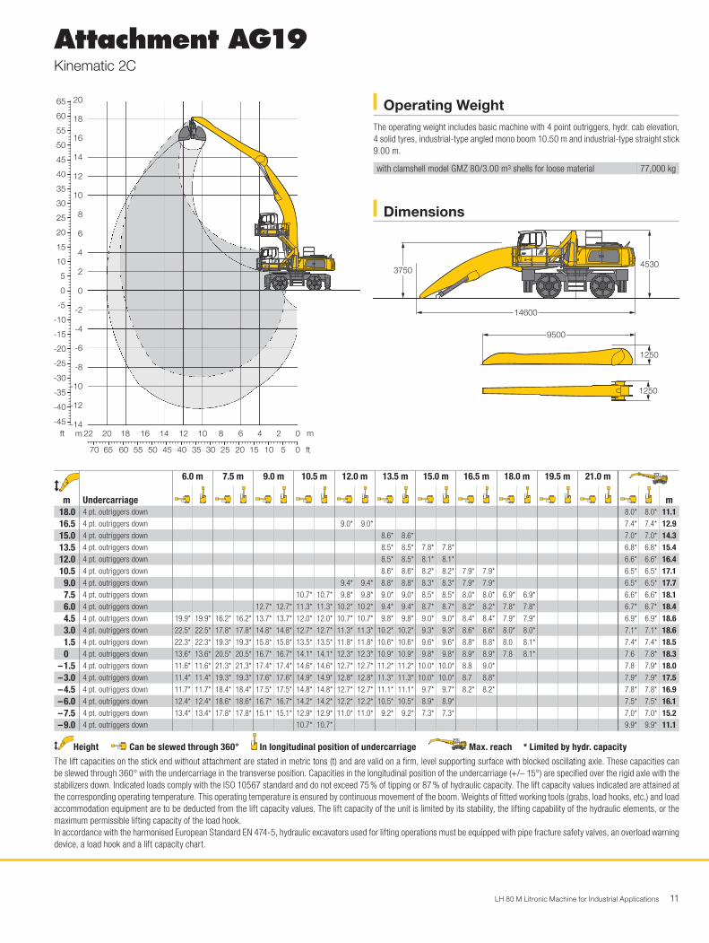
Operating WeightThe operating weight includes basic machine with 4 point outriggers, hydr. cab elevation, 4 solid tyres, industrial-type angled mono boom 10.50 m and industrial-type straight stick 9.00 m.
with clamshell model GMZ 80/3.00 m3 shells for loose material 77,000 kg
30
55
60
65
50
45
40
35
25
20
15
10
5
0
-5
-10
-15
-20
-25
-30
-35
-40
-45
8
10
12
14
16
18
20H0683
3540455055606570 30 25 20 15 10 5 0
121416182022 10 8 6 4 2 0
6
4
2
0
-2
-4
-6
-8
-10
-12
-14mft m
ft
14600
4530
H0684
3750
9500
1250
1250
m
Undercarriage
6.0 m 7.5 m 9.0 m 10.5 m 12.0 m 13.5 m 15.0 m 16.5 m 18.0 m 19.5 m 21.0 m
m18.0 4 pt. outriggers down 8.0* 8.0* 11.116.5 4 pt. outriggers down 9.0* 9.0* 7.4* 7.4* 12.915.0 4 pt. outriggers down 8.6* 8.6* 7.0* 7.0* 14.313.5 4 pt. outriggers down 8.5* 8.5* 7.8* 7.8* 6.8* 6.8* 15.412.0 4 pt. outriggers down 8.5* 8.5* 8.1* 8.1* 6.6* 6.6* 16.410.5 4 pt. outriggers down 8.6* 8.6* 8.2* 8.2* 7.9* 7.9* 6.5* 6.5* 17.1
9.0 4 pt. outriggers down 9.4* 9.4* 8.8* 8.8* 8.3* 8.3* 7.9* 7.9* 6.5* 6.5* 17.77.5 4 pt. outriggers down 10.7* 10.7* 9.8* 9.8* 9.0* 9.0* 8.5* 8.5* 8.0* 8.0* 6.9* 6.9* 6.6* 6.6* 18.16.0 4 pt. outriggers down 12.7* 12.7* 11.3* 11.3* 10.2* 10.2* 9.4* 9.4* 8.7* 8.7* 8.2* 8.2* 7.8* 7.8* 6.7* 6.7* 18.44.5 4 pt. outriggers down 19.9* 19.9* 16.2* 16.2* 13.7* 13.7* 12.0* 12.0* 10.7* 10.7* 9.8* 9.8* 9.0* 9.0* 8.4* 8.4* 7.9* 7.9* 6.9* 6.9* 18.63.0 4 pt. outriggers down 22.5* 22.5* 17.8* 17.8* 14.8* 14.8* 12.7* 12.7* 11.3* 11.3* 10.2* 10.2* 9.3* 9.3* 8.6* 8.6* 8.0* 8.0* 7.1* 7.1* 18.61.5 4 pt. outriggers down 22.3* 22.3* 19.3* 19.3* 15.8* 15.8* 13.5* 13.5* 11.8* 11.8* 10.6* 10.6* 9.6* 9.6* 8.8* 8.8* 8.0 8.1* 7.4* 7.4* 18.50 4 pt. outriggers down 13.6* 13.6* 20.5* 20.5* 16.7* 16.7* 14.1* 14.1* 12.3* 12.3* 10.9* 10.9* 9.8* 9.8* 8.9* 8.9* 7.8 8.1* 7.6 7.8* 18.3
– 1.5 4 pt. outriggers down 11.6* 11.6* 21.3* 21.3* 17.4* 17.4* 14.6* 14.6* 12.7* 12.7* 11.2* 11.2* 10.0* 10.0* 8.8 9.0* 7.8 7.9* 18.0– 3.0 4 pt. outriggers down 11.4* 11.4* 19.3* 19.3* 17.6* 17.6* 14.9* 14.9* 12.8* 12.8* 11.3* 11.3* 10.0* 10.0* 8.7 8.8* 7.9* 7.9* 17.5– 4.5 4 pt. outriggers down 11.7* 11.7* 18.4* 18.4* 17.5* 17.5* 14.8* 14.8* 12.7* 12.7* 11.1* 11.1* 9.7* 9.7* 8.2* 8.2* 7.8* 7.8* 16.9– 6.0 4 pt. outriggers down 12.4* 12.4* 18.6* 18.6* 16.7* 16.7* 14.2* 14.2* 12.2* 12.2* 10.5* 10.5* 8.9* 8.9* 7.5* 7.5* 16.1– 7.5 4 pt. outriggers down 13.4* 13.4* 17.8* 17.8* 15.1* 15.1* 12.9* 12.9* 11.0* 11.0* 9.2* 9.2* 7.3* 7.3* 7.0* 7.0* 15.2– 9.0 4 pt. outriggers down 10.7* 10.7* 9.9* 9.9* 11.1
Height Can be slewed through 360° In longitudinal position of undercarriage Max. reach * Limited by hydr. capacityThe lift capacities on the stick end without attachment are stated in metric tons (t) and are valid on a firm, level supporting surface with blocked oscillating axle. These capacities can be slewed through 360° with the undercarriage in the transverse position. Capacities in the longitudinal position of the undercarriage (+/– 15°) are specified over the rigid axle with the stabilizers down. Indicated loads comply with the ISO 10567 standard and do not exceed 75 % of tipping or 87 % of hydraulic capacity. The lift capacity values indicated are attained at the corresponding operating temperature. This operating temperature is ensured by continuous movement of the boom. Weights of fitted working tools (grabs, load hooks, etc.) and load accommodation equipment are to be deducted from the lift capacity values. The lift capacity of the unit is limited by its stability, the lifting capability of the hydraulic elements, or the maximum permissible lifting capacity of the load hook.In accordance with the harmonised European Standard EN 474-5, hydraulic excavators used for lifting operations must be equipped with pipe fracture safety valves, an overload warning device, a load hook and a lift capacity chart.
12 LH 80 M Litronic Machine for Industrial Applications
Attachment AG20Kinematic 2D
Dimensions
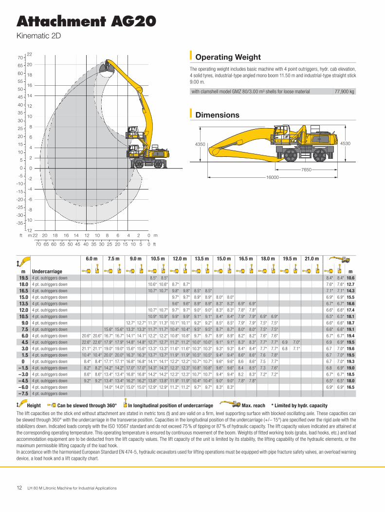
Operating WeightThe operating weight includes basic machine with 4 point outriggers, hydr. cab elevation, 4 solid tyres, industrial-type angled mono boom 11.50 m and industrial-type straight stick 9.00 m.
with clamshell model GMZ 80/3.00 m3 shells for loose material 77,900 kg
30
55
60
65
70
50
45
40
35
25
20
15
10
5
0
-5
-10
-15
-20
-25
-30
-35
8
10
12
14
16
18
20
22 H0677
3540455055606570 30 25 20 15 10 5 0
121416182022 10 8 6 4 2 0
6
4
2
0
-2
-4
-6
-8
-10
-12mft m
ft
7650
16000
4530
H0678
4350
m
Undercarriage
6.0 m 7.5 m 9.0 m 10.5 m 12.0 m 13.5 m 15.0 m 16.5 m 18.0 m 19.5 m 21.0 m
m19.5 4 pt. outriggers down 8.5* 8.5* 8.4* 8.4* 10.618.0 4 pt. outriggers down 10.6* 10.6* 8.7* 8.7* 7.6* 7.6* 12.716.5 4 pt. outriggers down 10.7* 10.7* 9.8* 9.8* 8.5* 8.5* 7.1* 7.1* 14.315.0 4 pt. outriggers down 9.7* 9.7* 8.9* 8.9* 8.0* 8.0* 6.9* 6.9* 15.513.5 4 pt. outriggers down 9.6* 9.6* 8.9* 8.9* 8.3* 8.3* 6.9* 6.9* 6.7* 6.7* 16.612.0 4 pt. outriggers down 10.7* 10.7* 9.7* 9.7* 9.0* 9.0* 8.3* 8.3* 7.8* 7.8* 6.6* 6.6* 17.410.5 4 pt. outriggers down 10.9* 10.9* 9.9* 9.9* 9.1* 9.1* 8.4* 8.4* 7.9* 7.9* 6.9* 6.9* 6.5* 6.5* 18.1
9.0 4 pt. outriggers down 12.7* 12.7* 11.3* 11.3* 10.1* 10.1* 9.2* 9.2* 8.5* 8.5* 7.9* 7.9* 7.5* 7.5* 6.6* 6.6* 18.77.5 4 pt. outriggers down 15.6* 15.6* 13.3* 13.3* 11.7* 11.7* 10.4* 10.4* 9.5* 9.5* 8.7* 8.7* 8.0* 8.0* 7.5* 7.5* 6.6* 6.6* 19.16.0 4 pt. outriggers down 20.6* 20.6* 16.7* 16.7* 14.1* 14.1* 12.2* 12.2* 10.8* 10.8* 9.7* 9.7* 8.9* 8.9* 8.2* 8.2* 7.6* 7.6* 6.7* 6.7* 19.44.5 4 pt. outriggers down 22.6* 22.6* 17.9* 17.9* 14.8* 14.8* 12.7* 12.7* 11.2* 11.2* 10.0* 10.0* 9.1* 9.1* 8.3* 8.3* 7.7* 7.7* 6.9 7.0* 6.9 6.9* 19.53.0 4 pt. outriggers down 21.1* 21.1* 19.0* 19.0* 15.6* 15.6* 13.3* 13.3* 11.6* 11.6* 10.3* 10.3* 9.3* 9.3* 8.4* 8.4* 7.7* 7.7* 6.8 7.1* 6.7 7.0* 19.61.5 4 pt. outriggers down 10.4* 10.4* 20.0* 20.0* 16.3* 16.3* 13.7* 13.7* 11.9* 11.9* 10.5* 10.5* 9.4* 9.4* 8.6* 8.6* 7.6 7.8* 6.7 7.0* 19.50 4 pt. outriggers down 8.4* 8.4* 17.1* 17.1* 16.8* 16.8* 14.1* 14.1* 12.2* 12.2* 10.7* 10.7* 9.6* 9.6* 8.6 8.6* 7.5 7.7* 6.7 7.0* 19.3
– 1.5 4 pt. outriggers down 8.2* 8.2* 14.2* 14.2* 17.0* 17.0* 14.3* 14.3* 12.3* 12.3* 10.8* 10.8* 9.6* 9.6* 8.4 8.5* 7.3 7.6* 6.8 6.9* 19.0– 3.0 4 pt. outriggers down 8.6* 8.6* 13.4* 13.4* 16.8* 16.8* 14.2* 14.2* 12.3* 12.3* 10.7* 10.7* 9.4* 9.4* 8.2 8.3* 7.2* 7.2* 6.7* 6.7* 18.5– 4.5 4 pt. outriggers down 9.2* 9.2* 13.4* 13.4* 16.2* 16.2* 13.8* 13.8* 11.9* 11.9* 10.4* 10.4* 9.0* 9.0* 7.8* 7.8* 6.5* 6.5* 18.0– 6.0 4 pt. outriggers down 14.0* 14.0* 15.0* 15.0* 12.9* 12.9* 11.2* 11.2* 9.7* 9.7* 8.3* 8.3* 6.9* 6.9* 16.5– 7.5 4 pt. outriggers down
Height Can be slewed through 360° In longitudinal position of undercarriage Max. reach * Limited by hydr. capacityThe lift capacities on the stick end without attachment are stated in metric tons (t) and are valid on a firm, level supporting surface with blocked oscillating axle. These capacities can be slewed through 360° with the undercarriage in the transverse position. Capacities in the longitudinal position of the undercarriage (+/– 15°) are specified over the rigid axle with the stabilizers down. Indicated loads comply with the ISO 10567 standard and do not exceed 75 % of tipping or 87 % of hydraulic capacity. The lift capacity values indicated are attained at the corresponding operating temperature. This operating temperature is ensured by continuous movement of the boom. Weights of fitted working tools (grabs, load hooks, etc.) and load accommodation equipment are to be deducted from the lift capacity values. The lift capacity of the unit is limited by its stability, the lifting capability of the hydraulic elements, or the maximum permissible lifting capacity of the load hook.In accordance with the harmonised European Standard EN 474-5, hydraulic excavators used for lifting operations must be equipped with pipe fracture safety valves, an overload warning device, a load hook and a lift capacity chart.
LH 80 M Litronic Machine for Industrial Applications 13
Attachment AG20Kinematic 2C
Dimensions
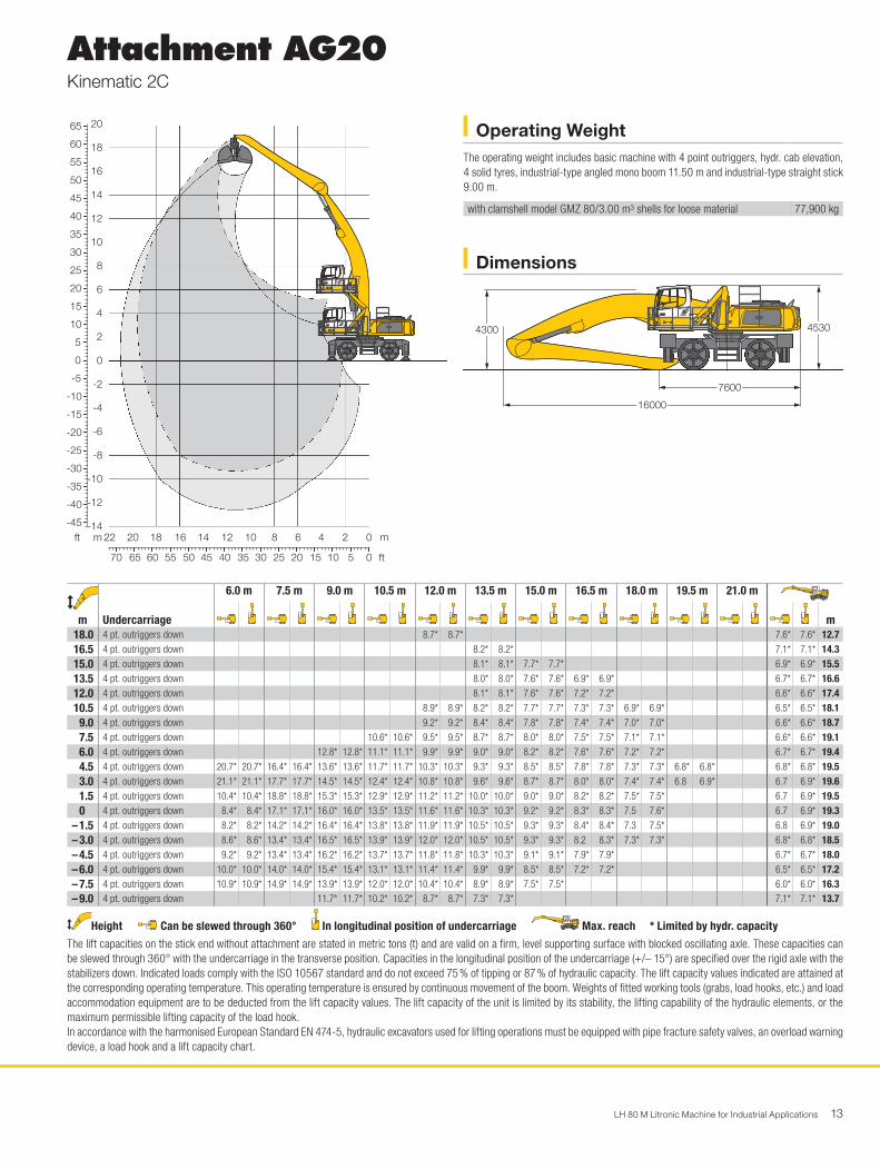
Operating WeightThe operating weight includes basic machine with 4 point outriggers, hydr. cab elevation, 4 solid tyres, industrial-type angled mono boom 11.50 m and industrial-type straight stick 9.00 m.
with clamshell model GMZ 80/3.00 m3 shells for loose material 77,900 kg
30
55
60
65
50
45
40
35
25
20
15
10
5
0
-5
-10
-15
-20
-25
-30
-35
-40
-45
8
10
12
14
16
18
20 H0685
3540455055606570 30 25 20 15 10 5 0
121416182022 10 8 6 4 2 0
6
4
2
0
-2
-4
-6
-8
-10
-14
-12
mft m
ft
7600
16000
4530
H0686
4300
m
Undercarriage
6.0 m 7.5 m 9.0 m 10.5 m 12.0 m 13.5 m 15.0 m 16.5 m 18.0 m 19.5 m 21.0 m
m18.0 4 pt. outriggers down 8.7* 8.7* 7.6* 7.6* 12.716.5 4 pt. outriggers down 8.2* 8.2* 7.1* 7.1* 14.315.0 4 pt. outriggers down 8.1* 8.1* 7.7* 7.7* 6.9* 6.9* 15.513.5 4 pt. outriggers down 8.0* 8.0* 7.6* 7.6* 6.9* 6.9* 6.7* 6.7* 16.612.0 4 pt. outriggers down 8.1* 8.1* 7.6* 7.6* 7.2* 7.2* 6.6* 6.6* 17.410.5 4 pt. outriggers down 8.9* 8.9* 8.2* 8.2* 7.7* 7.7* 7.3* 7.3* 6.9* 6.9* 6.5* 6.5* 18.1
9.0 4 pt. outriggers down 9.2* 9.2* 8.4* 8.4* 7.8* 7.8* 7.4* 7.4* 7.0* 7.0* 6.6* 6.6* 18.77.5 4 pt. outriggers down 10.6* 10.6* 9.5* 9.5* 8.7* 8.7* 8.0* 8.0* 7.5* 7.5* 7.1* 7.1* 6.6* 6.6* 19.16.0 4 pt. outriggers down 12.8* 12.8* 11.1* 11.1* 9.9* 9.9* 9.0* 9.0* 8.2* 8.2* 7.6* 7.6* 7.2* 7.2* 6.7* 6.7* 19.44.5 4 pt. outriggers down 20.7* 20.7* 16.4* 16.4* 13.6* 13.6* 11.7* 11.7* 10.3* 10.3* 9.3* 9.3* 8.5* 8.5* 7.8* 7.8* 7.3* 7.3* 6.8* 6.8* 6.8* 6.8* 19.53.0 4 pt. outriggers down 21.1* 21.1* 17.7* 17.7* 14.5* 14.5* 12.4* 12.4* 10.8* 10.8* 9.6* 9.6* 8.7* 8.7* 8.0* 8.0* 7.4* 7.4* 6.8 6.9* 6.7 6.9* 19.61.5 4 pt. outriggers down 10.4* 10.4* 18.8* 18.8* 15.3* 15.3* 12.9* 12.9* 11.2* 11.2* 10.0* 10.0* 9.0* 9.0* 8.2* 8.2* 7.5* 7.5* 6.7 6.9* 19.50 4 pt. outriggers down 8.4* 8.4* 17.1* 17.1* 16.0* 16.0* 13.5* 13.5* 11.6* 11.6* 10.3* 10.3* 9.2* 9.2* 8.3* 8.3* 7.5 7.6* 6.7 6.9* 19.3
– 1.5 4 pt. outriggers down 8.2* 8.2* 14.2* 14.2* 16.4* 16.4* 13.8* 13.8* 11.9* 11.9* 10.5* 10.5* 9.3* 9.3* 8.4* 8.4* 7.3 7.5* 6.8 6.9* 19.0– 3.0 4 pt. outriggers down 8.6* 8.6* 13.4* 13.4* 16.5* 16.5* 13.9* 13.9* 12.0* 12.0* 10.5* 10.5* 9.3* 9.3* 8.2 8.3* 7.3* 7.3* 6.8* 6.8* 18.5– 4.5 4 pt. outriggers down 9.2* 9.2* 13.4* 13.4* 16.2* 16.2* 13.7* 13.7* 11.8* 11.8* 10.3* 10.3* 9.1* 9.1* 7.9* 7.9* 6.7* 6.7* 18.0– 6.0 4 pt. outriggers down 10.0* 10.0* 14.0* 14.0* 15.4* 15.4* 13.1* 13.1* 11.4* 11.4* 9.9* 9.9* 8.5* 8.5* 7.2* 7.2* 6.5* 6.5* 17.2– 7.5 4 pt. outriggers down 10.9* 10.9* 14.9* 14.9* 13.9* 13.9* 12.0* 12.0* 10.4* 10.4* 8.9* 8.9* 7.5* 7.5* 6.0* 6.0* 16.3– 9.0 4 pt. outriggers down 11.7* 11.7* 10.2* 10.2* 8.7* 8.7* 7.3* 7.3* 7.1* 7.1* 13.7
Height Can be slewed through 360° In longitudinal position of undercarriage Max. reach * Limited by hydr. capacityThe lift capacities on the stick end without attachment are stated in metric tons (t) and are valid on a firm, level supporting surface with blocked oscillating axle. These capacities can be slewed through 360° with the undercarriage in the transverse position. Capacities in the longitudinal position of the undercarriage (+/– 15°) are specified over the rigid axle with the stabilizers down. Indicated loads comply with the ISO 10567 standard and do not exceed 75 % of tipping or 87 % of hydraulic capacity. The lift capacity values indicated are attained at the corresponding operating temperature. This operating temperature is ensured by continuous movement of the boom. Weights of fitted working tools (grabs, load hooks, etc.) and load accommodation equipment are to be deducted from the lift capacity values. The lift capacity of the unit is limited by its stability, the lifting capability of the hydraulic elements, or the maximum permissible lifting capacity of the load hook.In accordance with the harmonised European Standard EN 474-5, hydraulic excavators used for lifting operations must be equipped with pipe fracture safety valves, an overload warning device, a load hook and a lift capacity chart.
14 LH 80 M Litronic Machine for Industrial Applications
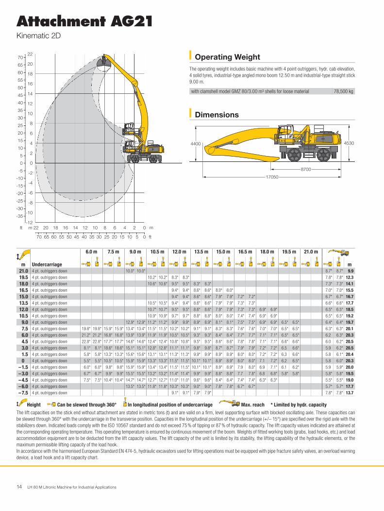
Attachment AG21Kinematic 2D
Dimensions
Operating WeightThe operating weight includes basic machine with 4 point outriggers, hydr. cab elevation, 4 solid tyres, industrial-type angled mono boom 12.50 m and industrial-type straight stick 9.00 m.
with clamshell model GMZ 80/3.00 m3 shells for loose material 78,500 kg
30
55
60
65
70
50
45
40
35
25
20
15
10
5
0
-5
-10
-15
-20
-25
-30
-35
8
10
12
14
16
18
20
22 H0679
3540455055606570 30 25 20 15 10 5 0
121416182022 10 8 6 4 2 0
6
4
2
0
-2
-4
-6
-8
-10
-12mft m
ft
H0680
8700
17050
45304400
m
Undercarriage
6.0 m 7.5 m 9.0 m 10.5 m 12.0 m 13.5 m 15.0 m 16.5 m 18.0 m 19.5 m 21.0 m
m21.0 4 pt. outriggers down 10.0* 10.0* 8.7* 8.7* 9.919.5 4 pt. outriggers down 10.2* 10.2* 8.3* 8.3* 7.8* 7.8* 12.318.0 4 pt. outriggers down 10.6* 10.6* 9.5* 9.5* 8.3* 8.3* 7.3* 7.3* 14.116.5 4 pt. outriggers down 9.4* 9.4* 8.6* 8.6* 8.0* 8.0* 7.0* 7.0* 15.515.0 4 pt. outriggers down 9.4* 9.4* 8.6* 8.6* 7.9* 7.9* 7.2* 7.2* 6.7* 6.7* 16.713.5 4 pt. outriggers down 10.5* 10.5* 9.4* 9.4* 8.6* 8.6* 7.9* 7.9* 7.3* 7.3* 6.6* 6.6* 17.712.0 4 pt. outriggers down 10.7* 10.7* 9.5* 9.5* 8.6* 8.6* 7.9* 7.9* 7.3* 7.3* 6.9* 6.9* 6.5* 6.5* 18.510.5 4 pt. outriggers down 10.9* 10.9* 9.7* 9.7* 8.8* 8.8* 8.0* 8.0* 7.4* 7.4* 6.9* 6.9* 6.5* 6.5* 19.2
9.0 4 pt. outriggers down 12.9* 12.9* 11.2* 11.2* 9.9* 9.9* 8.9* 8.9* 8.1* 8.1* 7.5* 7.5* 6.9* 6.9* 6.5* 6.5* 6.4* 6.4* 19.77.5 4 pt. outriggers down 19.8* 19.8* 15.9* 15.9* 13.4* 13.4* 11.5* 11.5* 10.2* 10.2* 9.1* 9.1* 8.3* 8.3* 7.6* 7.6* 7.0* 7.0* 6.5* 6.5* 6.3* 6.3* 20.16.0 4 pt. outriggers down 21.2* 21.2* 16.8* 16.8* 13.9* 13.9* 11.9* 11.9* 10.5* 10.5* 9.3* 9.3* 8.4* 8.4* 7.7* 7.7* 7.1* 7.1* 6.5* 6.5* 6.2 6.3* 20.34.5 4 pt. outriggers down 22.8* 22.8* 17.7* 17.7* 14.6* 14.6* 12.4* 12.4* 10.8* 10.8* 9.5* 9.5* 8.6* 8.6* 7.8* 7.8* 7.1* 7.1* 6.6* 6.6* 6.0 6.2* 20.53.0 4 pt. outriggers down 8.1* 8.1* 18.6* 18.6* 15.1* 15.1* 12.8* 12.8* 11.1* 11.1* 9.8* 9.8* 8.7* 8.7* 7.9* 7.9* 7.2* 7.2* 6.5 6.6* 5.9 6.2* 20.51.5 4 pt. outriggers down 5.8* 5.8* 13.3* 13.3* 15.6* 15.6* 13.1* 13.1* 11.3* 11.3* 9.9* 9.9* 8.9* 8.9* 8.0* 8.0* 7.2* 7.2* 6.3 6.6* 5.8 6.1* 20.40 4 pt. outriggers down 5.5* 5.5* 10.5* 10.5* 15.9* 15.9* 13.3* 13.3* 11.5* 11.5* 10.1* 10.1* 8.9* 8.9* 8.0* 8.0* 7.1 7.2* 6.2 6.5* 5.8 6.0* 20.3
– 1.5 4 pt. outriggers down 6.0* 6.0* 9.8* 9.8* 15.9* 15.9* 13.4* 13.4* 11.5* 11.5* 10.1* 10.1* 8.9* 8.9* 7.9 8.0* 6.9 7.1* 6.1 6.2* 5.9 5.9* 20.0– 3.0 4 pt. outriggers down 6.7* 6.7* 9.9* 9.9* 15.5* 15.5* 13.2* 13.2* 11.4* 11.4* 9.9* 9.9* 8.8* 8.8* 7.7 7.8* 6.8 6.8* 5.8* 5.8* 5.8* 5.8* 19.5– 4.5 4 pt. outriggers down 7.5* 7.5* 10.4* 10.4* 14.7* 14.7* 12.7* 12.7* 11.0* 11.0* 9.6* 9.6* 8.4* 8.4* 7.4* 7.4* 6.3* 6.3* 5.5* 5.5* 19.0– 6.0 4 pt. outriggers down 13.5* 13.5* 11.8* 11.8* 10.3* 10.3* 9.0* 9.0* 7.8* 7.8* 6.7* 6.7* 5.7* 5.7* 17.7– 7.5 4 pt. outriggers down 9.1* 9.1* 7.9* 7.9* 7.8* 7.8* 13.7
Height Can be slewed through 360° In longitudinal position of undercarriage Max. reach * Limited by hydr. capacityThe lift capacities on the stick end without attachment are stated in metric tons (t) and are valid on a firm, level supporting surface with blocked oscillating axle. These capacities can be slewed through 360° with the undercarriage in the transverse position. Capacities in the longitudinal position of the undercarriage (+/– 15°) are specified over the rigid axle with the stabilizers down. Indicated loads comply with the ISO 10567 standard and do not exceed 75 % of tipping or 87 % of hydraulic capacity. The lift capacity values indicated are attained at the corresponding operating temperature. This operating temperature is ensured by continuous movement of the boom. Weights of fitted working tools (grabs, load hooks, etc.) and load accommodation equipment are to be deducted from the lift capacity values. The lift capacity of the unit is limited by its stability, the lifting capability of the hydraulic elements, or the maximum permissible lifting capacity of the load hook.In accordance with the harmonised European Standard EN 474-5, hydraulic excavators used for lifting operations must be equipped with pipe fracture safety valves, an overload warning device, a load hook and a lift capacity chart.

LH 80 M Litronic Machine for Industrial Applications 15
Attachment AG21Kinematic 2C
Dimensions
Operating WeightThe operating weight includes basic machine with 4 point outriggers, hydr. cab elevation, 4 solid tyres, industrial-type angled mono boom 12.50 m and industrial-type straight stick 9.00 m.
with clamshell model GMZ 80/3.00 m3 shells for loose material 78,500 kg
30
55
60
65
70
50
45
40
35
25
20
15
10
5
0
-5
-10
-15
-20
-25
-30
-35
-40
-45
8
10
12
14
16
18
20
22 H0687
3540455055606570 30 25 20 15 10 5 0
121416182022 10 8 6 4 2 0
6
4
2
0
-2
-4
-6
-8
-10
-14
-12
mft m
ft
H0688
8700
17050
45304400
m
Undercarriage
6.0 m 7.5 m 9.0 m 10.5 m 12.0 m 13.5 m 15.0 m 16.5 m 18.0 m 19.5 m 21.0 m
m19.5 4 pt. outriggers down 8.3* 8.3* 7.8* 7.8* 12.318.0 4 pt. outriggers down 7.9* 7.9* 7.3* 7.3* 14.116.5 4 pt. outriggers down 7.7* 7.7* 7.2* 7.2* 7.0* 7.0* 15.515.0 4 pt. outriggers down 7.7* 7.7* 7.2* 7.2* 6.8* 6.8* 6.7* 6.7* 16.713.5 4 pt. outriggers down 7.7* 7.7* 7.2* 7.2* 6.7* 6.7* 6.4* 6.4* 17.712.0 4 pt. outriggers down 7.8* 7.8* 7.2* 7.2* 6.7* 6.7* 6.4* 6.4* 6.3* 6.3* 18.510.5 4 pt. outriggers down 8.7* 8.7* 7.9* 7.9* 7.3* 7.3* 6.8* 6.8* 6.4* 6.4* 6.1* 6.1* 19.2
9.0 4 pt. outriggers down 9.0* 9.0* 8.1* 8.1* 7.4* 7.4* 6.9* 6.9* 6.4* 6.4* 6.1* 6.1* 6.1* 6.1* 19.77.5 4 pt. outriggers down 12.0* 12.0* 10.4* 10.4* 9.2* 9.2* 8.3* 8.3* 7.6* 7.6* 7.0* 7.0* 6.5* 6.5* 6.1* 6.1* 6.0* 6.0* 20.16.0 4 pt. outriggers down 19.2* 19.2* 15.3* 15.3* 12.7* 12.7* 10.9* 10.9* 9.6* 9.6* 8.6* 8.6* 7.8* 7.8* 7.1* 7.1* 6.6* 6.6* 6.2* 6.2* 6.0* 6.0* 20.34.5 4 pt. outriggers down 21.0* 21.0* 16.3* 16.3* 13.4* 13.4* 11.4* 11.4* 9.9* 9.9* 8.8* 8.8* 8.0* 8.0* 7.3* 7.3* 6.7* 6.7* 6.3* 6.3* 6.0* 6.0* 20.53.0 4 pt. outriggers down 8.1* 8.1* 17.4* 17.4* 14.1* 14.1* 11.9* 11.9* 10.3* 10.3* 9.1* 9.1* 8.2* 8.2* 7.5* 7.5* 6.9* 6.9* 6.3* 6.3* 5.9 6.0* 20.51.5 4 pt. outriggers down 5.8* 5.8* 13.3* 13.3* 14.7* 14.7* 12.4* 12.4* 10.7* 10.7* 9.4* 9.4* 8.4* 8.4* 7.6* 7.6* 6.9* 6.9* 6.3 6.4* 5.8 6.0* 20.40 4 pt. outriggers down 5.5* 5.5* 10.5* 10.5* 15.2* 15.2* 12.7* 12.7* 10.9* 10.9* 9.6* 9.6* 8.6* 8.6* 7.7* 7.7* 7.0* 7.0* 6.2 6.3* 5.8 6.0* 20.3
– 1.5 4 pt. outriggers down 6.0* 6.0* 9.8* 9.8* 15.4* 15.4* 12.9* 12.9* 11.1* 11.1* 9.7* 9.7* 8.6* 8.6* 7.7* 7.7* 6.9 7.0* 6.1 6.2* 5.9 6.0* 20.0– 3.0 4 pt. outriggers down 6.7* 6.7* 9.9* 9.9* 15.3* 15.3* 12.9* 12.9* 11.2* 11.2* 9.8* 9.8* 8.6* 8.6* 7.7* 7.7* 6.8 6.8* 5.9* 5.9* 5.9* 5.9* 19.5– 4.5 4 pt. outriggers down 7.5* 7.5* 10.4* 10.4* 14.9* 14.9* 12.7* 12.7* 11.0* 11.0* 9.6* 9.6* 8.4* 8.4* 7.4* 7.4* 6.5* 6.5* 5.8* 5.8* 19.0– 6.0 4 pt. outriggers down 8.3* 8.3* 11.0* 11.0* 14.0* 14.0* 12.0* 12.0* 10.5* 10.5* 9.1* 9.1* 8.0* 8.0* 6.9* 6.9* 5.8* 5.8* 5.5* 5.5* 18.3– 7.5 4 pt. outriggers down 11.9* 11.9* 12.6* 12.6* 11.0* 11.0* 9.6* 9.6* 8.4* 8.4* 7.2* 7.2* 6.0* 6.0* 5.1* 5.1* 17.5– 9.0 4 pt. outriggers down 10.5* 10.5* 9.4* 9.4* 8.2* 8.2* 7.1* 7.1* 5.9* 5.9* 5.4* 5.4* 15.5
Height Can be slewed through 360° In longitudinal position of undercarriage Max. reach * Limited by hydr. capacityThe lift capacities on the stick end without attachment are stated in metric tons (t) and are valid on a firm, level supporting surface with blocked oscillating axle. These capacities can be slewed through 360° with the undercarriage in the transverse position. Capacities in the longitudinal position of the undercarriage (+/– 15°) are specified over the rigid axle with the stabilizers down. Indicated loads comply with the ISO 10567 standard and do not exceed 75 % of tipping or 87 % of hydraulic capacity. The lift capacity values indicated are attained at the corresponding operating temperature. This operating temperature is ensured by continuous movement of the boom. Weights of fitted working tools (grabs, load hooks, etc.) and load accommodation equipment are to be deducted from the lift capacity values. The lift capacity of the unit is limited by its stability, the lifting capability of the hydraulic elements, or the maximum permissible lifting capacity of the load hook.In accordance with the harmonised European Standard EN 474-5, hydraulic excavators used for lifting operations must be equipped with pipe fracture safety valves, an overload warning device, a load hook and a lift capacity chart.
16 LH 80 M Litronic Machine for Industrial Applications
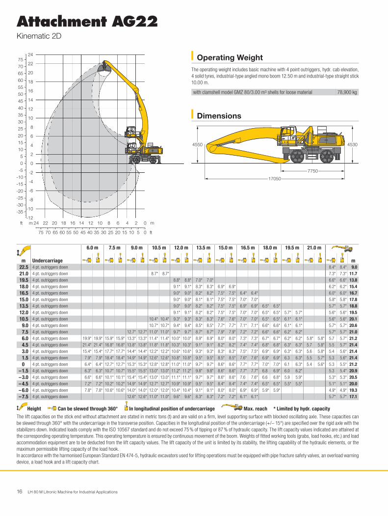
Attachment AG22Kinematic 2D
Dimensions
Operating WeightThe operating weight includes basic machine with 4 point outriggers, hydr. cab elevation, 4 solid tyres, industrial-type angled mono boom 12.50 m and industrial-type straight stick 10.00 m.
with clamshell model GMZ 80/3.00 m3 shells for loose material 78,900 kg
30
55
60
65
70
75
50
45
40
35
25
20
15
10
5
0
-5
-10
-15
-20
-25
-30
-35
8
10
12
14
16
18
20
22
24 H0681
354045505560657075 30 25 20 15 10 5 0
12141618202224 10 8 6 4 2 0
6
4
2
0
-2
-4
-6
-8
-10
-12mft m
ft
H0682
7750
17050
45304550
m
Undercarriage
6.0 m 7.5 m 9.0 m 10.5 m 12.0 m 13.5 m 15.0 m 16.5 m 18.0 m 19.5 m 21.0 m
m22.5 4 pt. outriggers down 8.4* 8.4* 9.021.0 4 pt. outriggers down 8.7* 8.7* 7.3* 7.3* 11.719.5 4 pt. outriggers down 8.8* 8.8* 7.0* 7.0* 6.6* 6.6* 13.818.0 4 pt. outriggers down 9.1* 9.1* 8.3* 8.3* 6.9* 6.9* 6.2* 6.2* 15.416.5 4 pt. outriggers down 9.0* 9.0* 8.2* 8.2* 7.5* 7.5* 6.4* 6.4* 6.0* 6.0* 16.715.0 4 pt. outriggers down 9.0* 9.0* 8.1* 8.1* 7.5* 7.5* 7.0* 7.0* 5.8* 5.8* 17.813.5 4 pt. outriggers down 9.0* 9.0* 8.2* 8.2* 7.5* 7.5* 6.9* 6.9* 6.5* 6.5* 5.7* 5.7* 18.812.0 4 pt. outriggers down 9.1* 9.1* 8.2* 8.2* 7.5* 7.5* 7.0* 7.0* 6.5* 6.5* 5.7* 5.7* 5.6* 5.6* 19.510.5 4 pt. outriggers down 10.4* 10.4* 9.3* 9.3* 8.3* 8.3* 7.6* 7.6* 7.0* 7.0* 6.5* 6.5* 6.1* 6.1* 5.6* 5.6* 20.1
9.0 4 pt. outriggers down 10.7* 10.7* 9.4* 9.4* 8.5* 8.5* 7.7* 7.7* 7.1* 7.1* 6.6* 6.6* 6.1* 6.1* 5.7* 5.7* 20.67.5 4 pt. outriggers down 12.7* 12.7* 11.0* 11.0* 9.7* 9.7* 8.7* 8.7* 7.9* 7.9* 7.2* 7.2* 6.6* 6.6* 6.2* 6.2* 5.7* 5.7* 21.06.0 4 pt. outriggers down 19.9* 19.9* 15.9* 15.9* 13.3* 13.3* 11.4* 11.4* 10.0* 10.0* 8.9* 8.9* 8.0* 8.0* 7.3* 7.3* 6.7* 6.7* 6.2* 6.2* 5.8* 5.8* 5.7 5.7* 21.24.5 4 pt. outriggers down 21.4* 21.4* 16.8* 16.8* 13.8* 13.8* 11.8* 11.8* 10.3* 10.3* 9.1* 9.1* 8.2* 8.2* 7.4* 7.4* 6.8* 6.8* 6.3* 6.3* 5.7 5.8* 5.5 5.7* 21.43.0 4 pt. outriggers down 15.4* 15.4* 17.7* 17.7* 14.4* 14.4* 12.2* 12.2* 10.6* 10.6* 9.3* 9.3* 8.3* 8.3* 7.5* 7.5* 6.9* 6.9* 6.3* 6.3* 5.6 5.8* 5.4 5.6* 21.41.5 4 pt. outriggers down 7.9* 7.9* 18.4* 18.4* 14.9* 14.9* 12.6* 12.6* 10.8* 10.8* 9.5* 9.5* 8.5* 8.5* 7.6* 7.6* 6.9* 6.9* 6.3 6.3* 5.5 5.7* 5.3 5.6* 21.40 4 pt. outriggers down 6.4* 6.4* 12.7* 12.7* 15.3* 15.3* 12.8* 12.8* 11.0* 11.0* 9.7* 9.7* 8.6* 8.6* 7.7* 7.7* 7.0* 7.0* 6.1 6.3* 5.4 5.6* 5.3 5.5* 21.2
– 1.5 4 pt. outriggers down 6.3* 6.3* 10.7* 10.7* 15.5* 15.5* 13.0* 13.0* 11.2* 11.2* 9.8* 9.8* 8.6* 8.6* 7.7* 7.7* 6.8 6.9* 6.0 6.2* 5.3 5.4* 20.9– 3.0 4 pt. outriggers down 6.6* 6.6* 10.1* 10.1* 15.4* 15.4* 13.0* 13.0* 11.1* 11.1* 9.7* 9.7* 8.6* 8.6* 7.6 7.6* 6.6 6.8* 5.9 5.9* 5.3* 5.3* 20.5– 4.5 4 pt. outriggers down 7.2* 7.2* 10.2* 10.2* 14.9* 14.9* 12.7* 12.7* 10.9* 10.9* 9.5* 9.5* 8.4* 8.4* 7.4* 7.4* 6.5* 6.5* 5.5* 5.5* 5.1* 5.1* 20.0– 6.0 4 pt. outriggers down 7.8* 7.8* 10.6* 10.6* 14.0* 14.0* 12.0* 12.0* 10.4* 10.4* 9.1* 9.1* 8.0* 8.0* 6.9* 6.9* 5.9* 5.9* 4.9* 4.9* 19.3– 7.5 4 pt. outriggers down 12.6* 12.6* 11.0* 11.0* 9.6* 9.6* 8.3* 8.3* 7.2* 7.2* 6.1* 6.1* 5.7* 5.7* 17.1
Height Can be slewed through 360° In longitudinal position of undercarriage Max. reach * Limited by hydr. capacityThe lift capacities on the stick end without attachment are stated in metric tons (t) and are valid on a firm, level supporting surface with blocked oscillating axle. These capacities can be slewed through 360° with the undercarriage in the transverse position. Capacities in the longitudinal position of the undercarriage (+/– 15°) are specified over the rigid axle with the stabilizers down. Indicated loads comply with the ISO 10567 standard and do not exceed 75 % of tipping or 87 % of hydraulic capacity. The lift capacity values indicated are attained at the corresponding operating temperature. This operating temperature is ensured by continuous movement of the boom. Weights of fitted working tools (grabs, load hooks, etc.) and load accommodation equipment are to be deducted from the lift capacity values. The lift capacity of the unit is limited by its stability, the lifting capability of the hydraulic elements, or the maximum permissible lifting capacity of the load hook.In accordance with the harmonised European Standard EN 474-5, hydraulic excavators used for lifting operations must be equipped with pipe fracture safety valves, an overload warning device, a load hook and a lift capacity chart.

LH 80 M Litronic Machine for Industrial Applications 17
Attachment AG22Kinematic 2C
Dimensions
Operating WeightThe operating weight includes basic machine with 4 point outriggers, hydr. cab elevation, 4 solid tyres, industrial-type angled mono boom 12.50 m and industrial-type straight stick 10.00 m.
with clamshell model GMZ 80/3.00 m3 shells for loose material 78,900 kg
30
55
60
65
70
50
45
40
35
25
20
15
10
5
0
-5
-10
-15
-20
-25
-30
-35
-40
-45
8
10
12
14
16
18
20
22 H0689
354045505560657075 30 25 20 15 10 5 0
121416182024 22 10 8 6 4 2 0
6
4
2
0
-2
-4
-6
-8
-10
-12
-14mft m
ft
H0690
7750
17050
45304550
m
Undercarriage
6.0 m 7.5 m 9.0 m 10.5 m 12.0 m 13.5 m 15.0 m 16.5 m 18.0 m 19.5 m 21.0 m
m19.5 4 pt. outriggers down 7.0* 7.0* 6.6* 6.6* 13.818.0 4 pt. outriggers down 6.9* 6.9* 6.2* 6.2* 15.416.5 4 pt. outriggers down 6.8* 6.8* 6.4* 6.4* 6.0* 6.0* 16.715.0 4 pt. outriggers down 6.7* 6.7* 6.3* 6.3* 5.8* 5.8* 17.813.5 4 pt. outriggers down 6.7* 6.7* 6.3* 6.3* 5.9* 5.9* 5.7* 5.7* 18.812.0 4 pt. outriggers down 6.8* 6.8* 6.3* 6.3* 5.9* 5.9* 5.6* 5.6* 5.6* 5.6* 19.510.5 4 pt. outriggers down 7.5* 7.5* 6.9* 6.9* 6.4* 6.4* 6.0* 6.0* 5.7* 5.7* 5.5* 5.5* 20.1
9.0 4 pt. outriggers down 8.5* 8.5* 7.6* 7.6* 7.0* 7.0* 6.5* 6.5* 6.0* 6.0* 5.7* 5.7* 5.5* 5.5* 20.67.5 4 pt. outriggers down 8.7* 8.7* 7.9* 7.9* 7.2* 7.2* 6.6* 6.6* 6.1* 6.1* 5.7* 5.7* 5.4* 5.4* 21.06.0 4 pt. outriggers down 11.9* 11.9* 10.3* 10.3* 9.0* 9.0* 8.1* 8.1* 7.3* 7.3* 6.7* 6.7* 6.2* 6.2* 5.8* 5.8* 5.5* 5.5* 5.4* 5.4* 21.24.5 4 pt. outriggers down 19.5* 19.5* 15.3* 15.3* 12.6* 12.6* 10.8* 10.8* 9.4* 9.4* 8.4* 8.4* 7.5* 7.5* 6.9* 6.9* 6.4* 6.4* 5.9* 5.9* 5.5* 5.5* 5.4* 5.4* 21.43.0 4 pt. outriggers down 15.4* 15.4* 16.3* 16.3* 13.3* 13.3* 11.2* 11.2* 9.8* 9.8* 8.6* 8.6* 7.8* 7.8* 7.1* 7.1* 6.5* 6.5* 6.0* 6.0* 5.6* 5.6* 5.4 5.4* 21.41.5 4 pt. outriggers down 7.9* 7.9* 17.2* 17.2* 13.9* 13.9* 11.7* 11.7* 10.1* 10.1* 8.9* 8.9* 8.0* 8.0* 7.2* 7.2* 6.6* 6.6* 6.1* 6.1* 5.5 5.6* 5.3 5.4* 21.40 4 pt. outriggers down 6.4* 6.4* 12.7* 12.7* 14.5* 14.5* 12.1* 12.1* 10.4* 10.4* 9.2* 9.2* 8.1* 8.1* 7.3* 7.3* 6.7* 6.7* 6.1* 6.1* 5.4 5.5* 5.3 5.4* 21.2
– 1.5 4 pt. outriggers down 6.3* 6.3* 10.7* 10.7* 14.9* 14.9* 12.4* 12.4* 10.7* 10.7* 9.3* 9.3* 8.3* 8.3* 7.4* 7.4* 6.7* 6.7* 6.0 6.1* 5.3 5.4* 20.9– 3.0 4 pt. outriggers down 6.6* 6.6* 10.1* 10.1* 15.0* 15.0* 12.6* 12.6* 10.8* 10.8* 9.4* 9.4* 8.3* 8.3* 7.4* 7.4* 6.6 6.7* 5.9 5.9* 5.4* 5.4* 20.5– 4.5 4 pt. outriggers down 7.2* 7.2* 10.2* 10.2* 14.8* 14.8* 12.5* 12.5* 10.8* 10.8* 9.4* 9.4* 8.3* 8.3* 7.3* 7.3* 6.5* 6.5* 5.6* 5.6* 5.3* 5.3* 20.0– 6.0 4 pt. outriggers down 7.8* 7.8* 10.6* 10.6* 14.2* 14.2* 12.1* 12.1* 10.5* 10.5* 9.1* 9.1* 8.0* 8.0* 7.0* 7.0* 6.1* 6.1* 5.2* 5.2* 19.3– 7.5 4 pt. outriggers down 8.5* 8.5* 11.2* 11.2* 13.2* 13.2* 11.4* 11.4* 9.9* 9.9* 8.6* 8.6* 7.5* 7.5* 6.4* 6.4* 5.3* 5.3* 4.9* 4.9* 18.5– 9.0 4 pt. outriggers down 12.0* 12.0* 11.6* 11.6* 10.1* 10.1* 8.8* 8.8* 7.7* 7.7* 6.6* 6.6* 5.4* 5.4* 4.4* 4.4* 17.6– 10.5 4 pt. outriggers down 8.3* 8.3* 7.3* 7.3* 6.2* 6.2* 5.9* 5.9* 13.9
Height Can be slewed through 360° In longitudinal position of undercarriage Max. reach * Limited by hydr. capacityThe lift capacities on the stick end without attachment are stated in metric tons (t) and are valid on a firm, level supporting surface with blocked oscillating axle. These capacities can be slewed through 360° with the undercarriage in the transverse position. Capacities in the longitudinal position of the undercarriage (+/– 15°) are specified over the rigid axle with the stabilizers down. Indicated loads comply with the ISO 10567 standard and do not exceed 75 % of tipping or 87 % of hydraulic capacity. The lift capacity values indicated are attained at the corresponding operating temperature. This operating temperature is ensured by continuous movement of the boom. Weights of fitted working tools (grabs, load hooks, etc.) and load accommodation equipment are to be deducted from the lift capacity values. The lift capacity of the unit is limited by its stability, the lifting capability of the hydraulic elements, or the maximum permissible lifting capacity of the load hook.In accordance with the harmonised European Standard EN 474-5, hydraulic excavators used for lifting operations must be equipped with pipe fracture safety valves, an overload warning device, a load hook and a lift capacity chart.
18 LH 80 M Litronic Machine for Industrial Applications
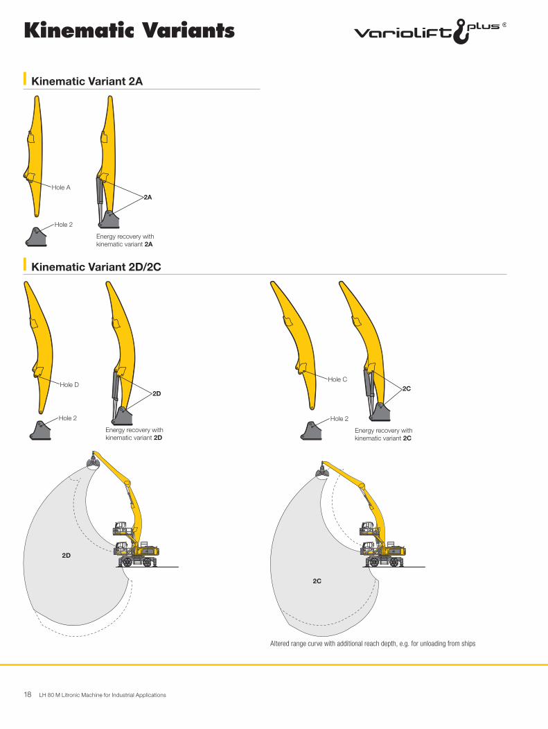
Altered range curve with additional reach depth, e.g. for unloading from ships
2D
H0702
2CH0701
Kinematic Variants
Kinematic Variant 2A
Kinematic Variant 2D/2C
2A
H0626
Hole 2
Hole A
Energy recovery with kinematic variant 2A
2D
H0628
Hole 2
Hole D
Energy recovery with kinematic variant 2D
2C
H0627
Hole 2
Hole C
Energy recovery with kinematic variant 2C
LH 80 M Litronic Machine for Industrial Applications 19
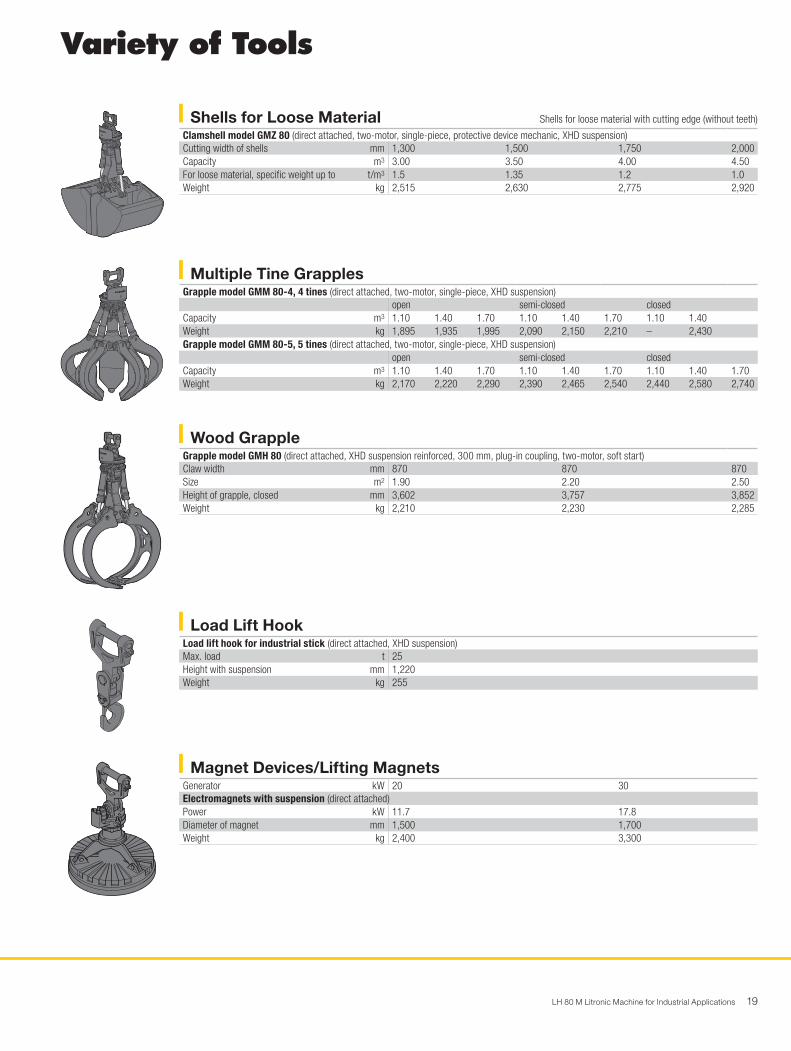
Variety of Tools
Shells for Loose Material Shells for loose material with cutting edge (without teeth)
Clamshell model GMZ 80 (direct attached, two-motor, single-piece, protective device mechanic, XHD suspension)Cutting width of shells mm 1,300 1,500 1,750 2,000Capacity m3 3.00 3.50 4.00 4.50For loose material, specific weight up to t/m3 1.5 1.35 1.2 1.0Weight kg 2,515 2,630 2,775 2,920
Wood GrappleGrapple model GMH 80 (direct attached, XHD suspension reinforced, 300 mm, plug-in coupling, two-motor, soft start)Claw width mm 870 870 870Size m2 1.90 2.20 2.50Height of grapple, closed mm 3,602 3,757 3,852Weight kg 2,210 2,230 2,285
Magnet Devices/Lifting MagnetsGenerator kW 20 30Electromagnets with suspension (direct attached)Power kW 11.7 17.8Diameter of magnet mm 1,500 1,700Weight kg 2,400 3,300
Load Lift HookLoad lift hook for industrial stick (direct attached, XHD suspension)Max. load t 25Height with suspension mm 1,220Weight kg 255
Multiple Tine GrapplesGrapple model GMM 80-4, 4 tines (direct attached, two-motor, single-piece, XHD suspension)
open semi-closed closedCapacity m3 1.10 1.40 1.70 1.10 1.40 1.70 1.10 1.40Weight kg 1,895 1,935 1,995 2,090 2,150 2,210 – 2,430Grapple model GMM 80-5, 5 tines (direct attached, two-motor, single-piece, XHD suspension)
open semi-closed closedCapacity m3 1.10 1.40 1.70 1.10 1.40 1.70 1.10 1.40 1.70Weight kg 2,170 2,220 2,290 2,390 2,465 2,540 2,440 2,580 2,740
20 LH 80 M Litronic Machine for Industrial Applications
B
A
B A
ERC
BA
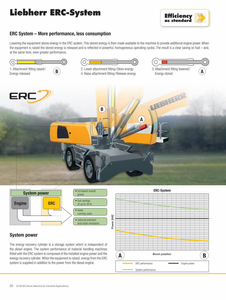
1. Attachment fitting raised /Energy released
2. Lower attachment fitting / Store energy4. Raise attachment fitting / Release energy
3. Attachment fitting lowered / Energy stored
System power
The energy recovery cylinder is a storage system which is independent of the diesel engine. The system performance of material handling machines fitted with the ERC system is composed of the installed engine power and the energy recovery cylinder. When the equipment is raised, energy from the ERC system is supplied in addition to the power from the diesel engine.
• increased overall powerSystem power
Engine• fuel savings of up to 30 %
• lower running costs
• reduced pollutant and noise emissions
ERC System – More performance, less consumption
Lowering the equipment stores energy in the ERC system. This stored energy is then made available to the machine to provide additional engine power. When the equipment is raised the stored energy is released and is reflected in powerful, homogeneous operating cycles. The result is a clear saving on fuel – and, at the same time, even greater performance.
Liebherr ERC-System Efficiencyas standard
ERC-System
Po
wer
[kW
]
Boom position
Engine powerERC performance
System performance
LH 80 M Litronic Machine for Industrial Applications 21
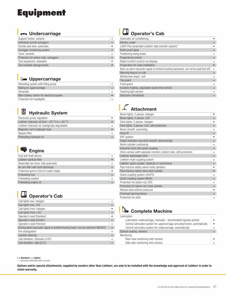
Equipment
• = Standard, + = Option* = optionally extendable after one year
Options and/or special attachments, supplied by vendors other than Liebherr, are only to be installed with the knowledge and approval of Liebherr in order to retain warranty.
UndercarriageSupport rocker, variants +Individual control outriggers +Shuttle axle lock, automatic •Outrigger monitoring system +Tyres, variants +Protection for piston rods, outriggers +Tool equipment, extended •Two lockable storage boxes •
Operator’s CabAutomatic air conditioning •Electric cooler +LiDAT Plus (extended Liebherr data transfer system) * •Bullet proof glass +Positioning swing brake +Proportional control +Radio Comfort (control via display) +Preparation for radio installation •Back-up alarm (acoustic signal is emitted traveling backward, can not be switched off) +Warning beacon on cab +Windscreen wiper, roof +Top guard +Front guard +Auxiliary heating, adjustable (week time switch) +Flashing light (xenon) +Electronic immobilizer +
AttachmentBoom lights, 2 pieces, halogen •Boom lights, 2 pieces, LED +Stick lights, 2 pieces, halogen •Stick lights, 2 pieces, LED, with protection +Boom shutoff, ascending +AutoLift +ERC system •Height limitation and stick shutoff, electronically +Boom cylinder cushioning +Industrial stick with quick coupling +Stick camera (with separate monitor), bottom side, with protection +Liebherr lightweight stick +Liebherr multi coupling system +Liebherr quick coupler, hydraulic or mechanical +Pipe fracture safety valves hoist cylinders •Pipe fracture safety valve stick cylinder •Quick coupling system LIKUFIX +Quick coupling system MH40 +Protection for piston rod, ERC +Protection for piston rod, hoist cylinder +Retract stick without pressure •Overload warning device +Protection for stick +
UppercarriageRefuelling system with filling pump +Railing on uppercarriage +Generator +Main battery switch for electrical system •Protection for headlights +
Hydraulic SystemElectronic pump regulation •Liebherr hydraulic oil from – 20 °C to + 40 °C •Liebherr hydraulic oil, biologically degradable +Magnetic rod in hydraulic tank •Bypass filter +Preheating hydraulic oil +
EngineFuel anti-theft device +Liebherr particle filter •Reversible fan drive, fully automatic +Air pre-filter with dust discharge +Protective grid in front of cooler intake •Preheating fuel +Preheating coolant +Preheating engine oil +
Operator’s CabCab lights rear, halogen +Cab lights rear, LED +Cab lights front, halogen •Cab lights front, LED +Operator’s seat Standard •Operator’s seat Comfort +Operator’s seat Premium +Driving alarm (acoustic signal is emitted during travel, can be switched ON/OFF) +Fire extinguisher +Joystick steering +Cab elevation, hydraulic (LHC) +Cab elevation, rigid (LFC) +
Complete MachineLubrication
Lubrication undercarriage, manually – decentralized (grease points) •Central lubrication system for uppercarriage and attachment, automatically •Central lubrication system for undercarriage, automatically +
Special coating, variants +Monitoring
Rear view monitoring with camera •Side view monitoring with camera +
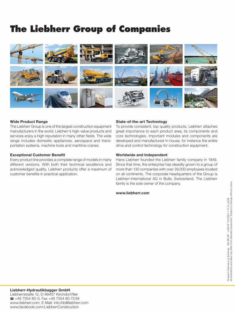
Wide Product RangeThe Liebherr Group is one of the largest construction equipment manufacturers in the world. Liebherr’s high-value products and services enjoy a high reputation in many other fields. The wide range includes domestic appliances, aerospace and trans-portation systems, machine tools and maritime cranes.
Exceptional Customer BenefitEvery product line provides a complete range of models in many different versions. With both their technical excellence and acknowledged quality, Liebherr products offer a maximum of customer benefits in practical application.
State-of-the-art TechnologyTo provide consistent, top quality products, Liebherr attaches great importance to each product area, its components and core technologies. Important modules and components are developed and manufactured in-house, for instance the entire drive and control technology for construction equipment.
Worldwide and IndependentHans Liebherr founded the Liebherr family company in 1949. Since that time, the enterprise has steadily grown to a group of more than 130 companies with over 39,000 employees located on all continents. The corporate headquarters of the Group is Liebherr-International AG in Bulle, Switzerland. The Liebherr family is the sole owner of the company.
www.liebherr.com
The Liebherr Group of Companies
Liebherr-Hydraulikbagger GmbH Liebherrstraße 12, D-88457 Kirchdorf/Iller S +49 7354 80-0, Fax +49 7354 80-72 94 www.liebherr.com, E-Mail: [email protected] www.facebook.com/LiebherrConstruction
Prin
ted
in G
erm
any
by S
chirm
er
RG
-BK
-RP
LH
B/V
F 11
2129
21-1
-11.
14_e
nGB
A
ll ill
ustr
atio
ns a
nd d
ata
may
diff
er fr
om s
tand
ard
equi
pmen
t. S
ubje
ct to
cha
nge
with
out n
otic
e.