machine for a 934 c hd erc industrial applications
TRANSCRIPT
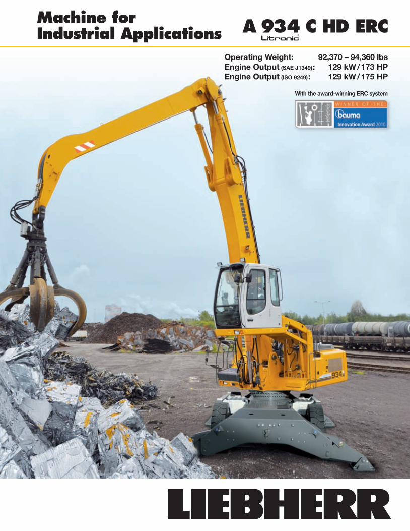
Machine for Industrial Applications A 934 C HD ERC
Operating Weight: 92,370 – 94,360 lbsEngine Output (SAE J1349): 129 kW / 173 HPEngine Output (ISO 9249): 129 kW / 175 HP
With the award-winning ERC system
A934C_HD_ERC_US.indd 1 17.07.12 14:14
A 934 C HD ERC
2 A 934 C HD ERC Litronic Machine for Industrial Applications
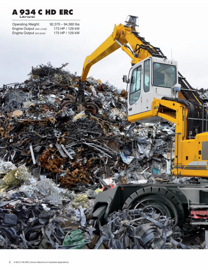
Operating Weight: 92,370 – 94,360 lbsEngine Output (SAE J1349): 173 HP / 129 kWEngine Output (ISO 9249): 175 HP / 129 kW
A934C_HD_ERC_US.indd 2 17.07.12 14:14
3A 934 C HD ERC Litronic Machine for Industrial Applications
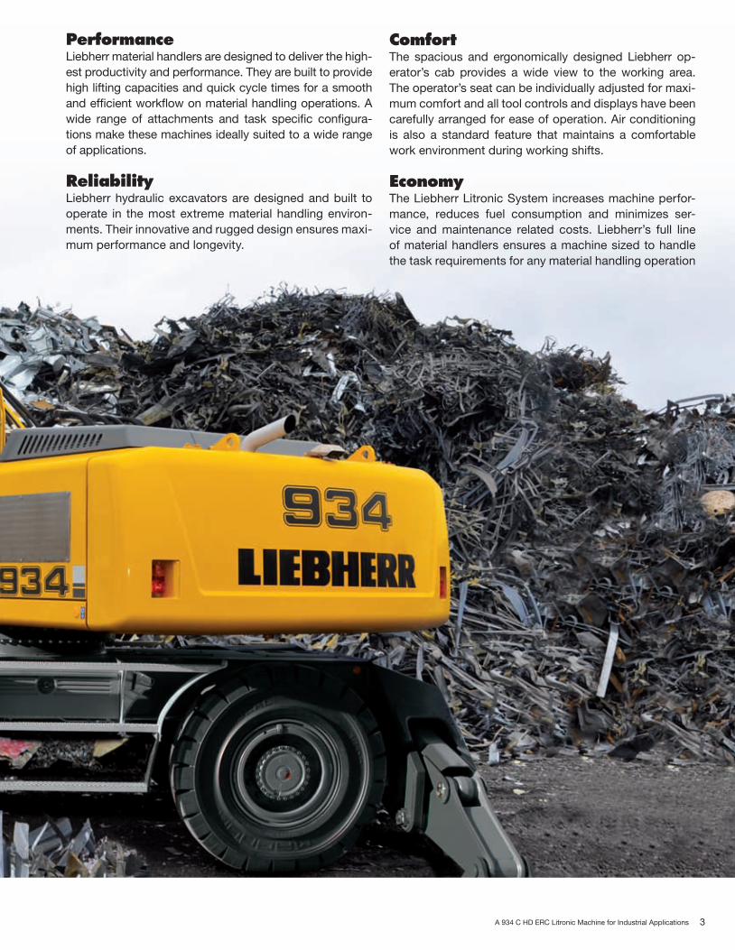
ComfortThe spacious and ergonomically designed Liebherr op-erator’s cab provides a wide view to the working area. The operator’s seat can be individually adjusted for maxi-mum comfort and all tool controls and displays have been carefully arranged for ease of operation. Air conditioning is also a standard feature that maintains a comfortable work environment during working shifts.
EconomyThe Liebherr Litronic System increases machine perfor-mance, reduces fuel consumption and minimizes ser-vice and maintenance related costs. Liebherr’s full line of material handlers ensures a machine sized to handle the task requirements for any material handling operation
PerformanceLiebherr material handlers are designed to deliver the high-est productivity and performance. They are built to provide high lifting capacities and quick cycle times for a smooth and efficient workflow on material handling operations. A wide range of attachments and task specific configura-tions make these machines ideally suited to a wide range of applications.
ReliabilityLiebherr hydraulic excavators are designed and built to operate in the most extreme material handling environ-ments. Their innovative and rugged design ensures maxi-mum performance and longevity.
A934C_HD_ERC_US.indd 3 17.07.12 14:14
4 A 934 C HD ERC Litronic Machine for Industrial Applications
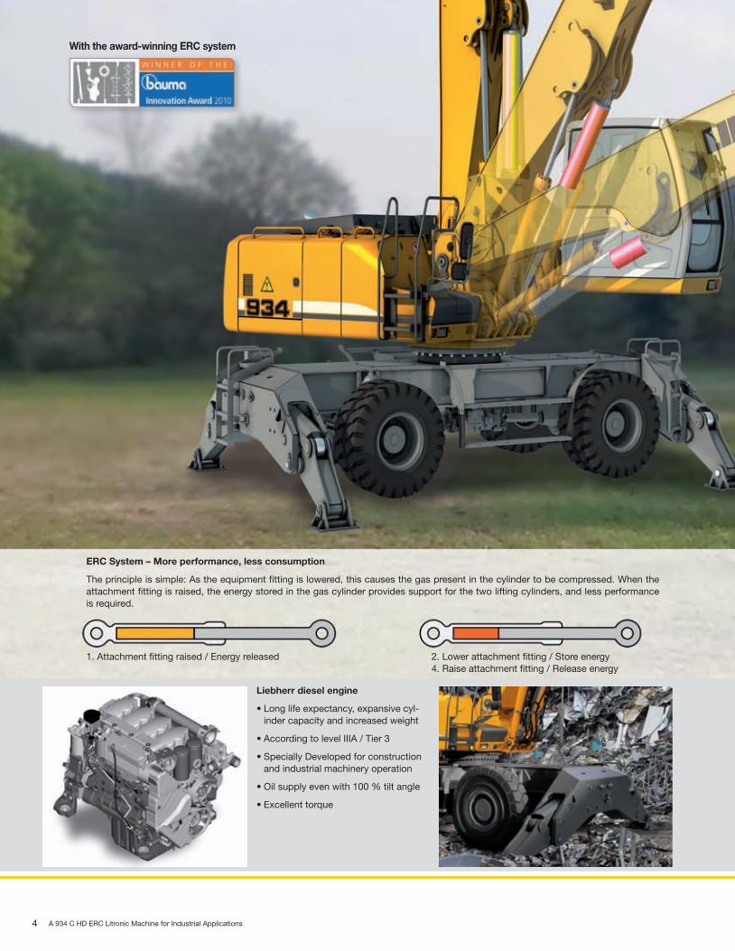
ERC System – More performance, less consumption
The principle is simple: As the equipment fitting is lowered, this causes the gas present in the cylinder to be compressed. When the attachment fitting is raised, the energy stored in the gas cylinder provides support for the two lifting cylinders, and less performance is required.
1. Attachment fitting raised / Energy released 2. Lower attachment fitting / Store energy 4. Raise attachment fitting / Release energy
With the award-winning ERC system
Liebherr diesel engine
•Longlifeexpectancy,expansivecyl-inder capacity and increased weight
•AccordingtolevelIIIA/Tier3
•SpeciallyDevelopedforconstructionand industrial machinery operation
•Oilsupplyevenwith100%tiltangle
•Excellenttorque
A934C_HD_ERC_US.indd 4 17.07.12 14:14

5A 934 C HD ERC Litronic Machine for Industrial Applications
Performance
3. Attachment fitting lowered / Energy stored
Robust undercarriage
•Thebox-typeconstructionoftheunder-carriage with securely-welded supports provides a solid base, the greatest stability and a long service life in every application
•Anadditionaldozerbladecanbeselected
•2-rangepowershifttransmission for stepless acceleration
Litronic-System
•Increasesproductivity of the excavator
•Reducesfuelconsumption
•Reducesservicecosts and eases operation
•Allowsmaximumsensitivityand as many overlapping movements as are required
The A 934 C HD Litronic has been designed for maximum productivity. Precise-ly engineered, the Liebherr developed and Liebherr manufactured components including the diesel engine, hydraulic pumps and motors, as well as swing gear and cylinders, guarantee maximum performance. This results in a high lifting capacity with fast working cycles.
Innovative solutionsMultiple attachments Liebherr can provide a machine for any material
handling application. A straight or angled indus-trial mono boom can be combined with various industrial sticks and a wide array of attachments to handle any task.
High lifting capacities The efficient handling of different materials, for example, scrap, wood, sand and gravel or bulk solids, is ensured by the most efficient use of the kinematics of the machine.
Quick cycle times A separate hydraulic circuit with a maximum hy-draulic pressure of 5500psi makes a high swing torque possible. Rapid work cycles are achieved through an independent control system.
Performance withoutcompromise
Maximum performance and maximum forces areavailable to the operator at all times.
ReGenerationPlus The new ReGenerationPlus system on the lifting cylinders saves energy and quickly lowers the at-tachment.
ERC System The energy stored by the lowering of the equip-ment in the ERC System gives the machine up to 107 HP in added performance capacity. This is re-leased again when the equipment is raised, and is also reflected in more powerful and more homog-enous work sequences. The result is a clear sav-ing on fuel – and, at the same time, even greater performance.
A934C_HD_ERC_US.indd 5 17.07.12 14:14
6 A 934 C HD ERC Litronic Machine for Industrial Applications
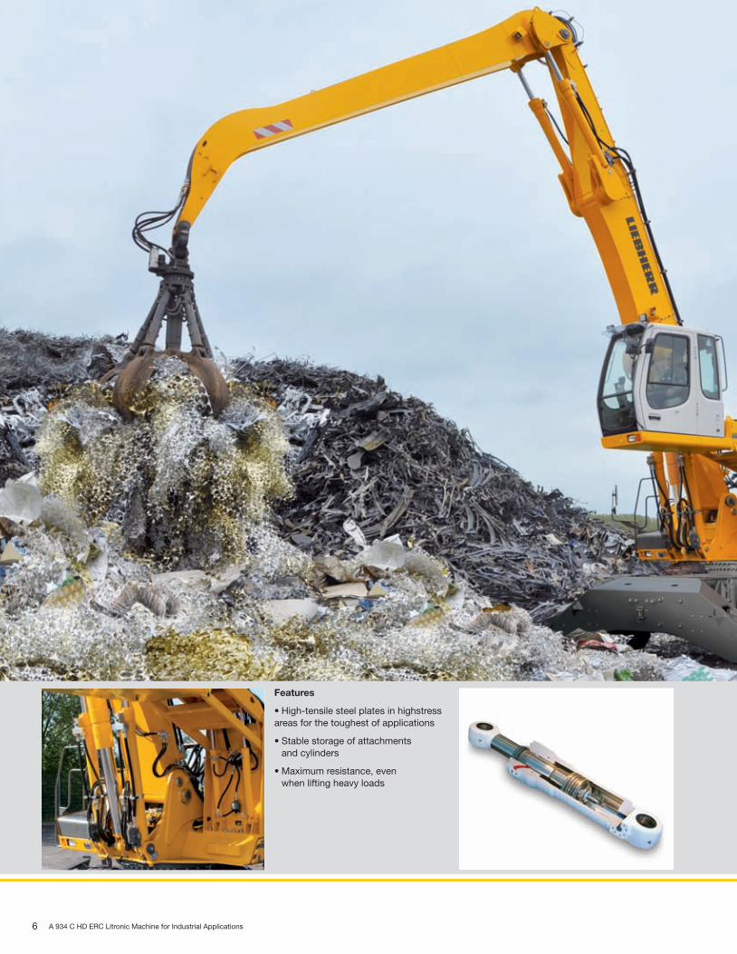
Features
•High-tensilesteelplatesinhighstressareas for the toughest of applications
•Stablestorageofattachments and cylinders
•Maximumresistance,even when lifting heavy loads
A934C_HD_ERC_US.indd 6 17.07.12 14:14

7A 934 C HD ERC Litronic Machine for Industrial Applications
Reliability
Liebherr hydraulic cylinders
•Specificsizeforeachmachine
•High-gradesurfacecoating of the piston rods
•AllLiebherrcylindersfeaturespeciallong-life sealing systems
•Shockabsorptionatbothsides in the working cylinders
Functional safety
•Essentialoperatingdataisstored and can be recalled at any time
•Controlandmonitoringfunctionsincrease functional safety of the machine
•Fourfixedworkingmodesforoutputdischarge facilitate an effective and efficient operation:
– ECO-Mode: High handling and loading performance coupled with low fuel consumption
– POWER-Mode:Formaximumhandlingandloading performance under severe conditions
– LIFT-Mode:forprecisehandlingofheavyloads – FINE-Mode:forfinecontrolatprecisionwork
Liebherr material handlers prove themselves day in and day out in a variety of applications throughout the world. Many years of experience as the world’s larg-est manufacturer of wheeled excavators along with continuous product develop-ment with the latest technology, have enabled Liebherr to offer a safe and reliable product to the market. With its rugged design and quality Liebherr products, the A934 C HD Litronic has been designed for performance and longevity.
Quality in detailLiebherr components Liebherr develops, tests and manufactures com-
ponents such as the diesel engine, slewing gear, hydraulic cylinders and electronics specifically for the material handling market. Parts, such as the engine and pumps, are being synchronized with each other as early as the initial build stage to en-sure a constant standard of quality.
Functional safety Safety oriented components are built as standard into the base units by Liebherr. The operator can concentrate fully on the task at hand knowing that the integrated on board electronics are performing a constant check using pre-defined data to keep the operator and others on the job site safe.A magnetic bar is fitted into the hydraulic tank as standard to help increase the operating life of the hydraulic system.
Rugged attachmentsWorking attachment The stable attachments are designed for the
harshest applications and have a long service life. AllcomponentshavebeenoptimisedusingtheFEmethod. Stress-reducing two-sided cylinder bear-ings on mono and arm connections. Integrated large diameter torsion tube for the best possible force absorption by the attachment components.
Piping Routing the hydraulic lines in the arm offers the best protection against damage. The electric cabling is made with high-grade materials, thus guaranteeing a reliable supply to the consumer.
A934C_HD_ERC_US.indd 7 17.07.12 14:14
8 A 934 C HD ERC Litronic Machine for Industrial Applications
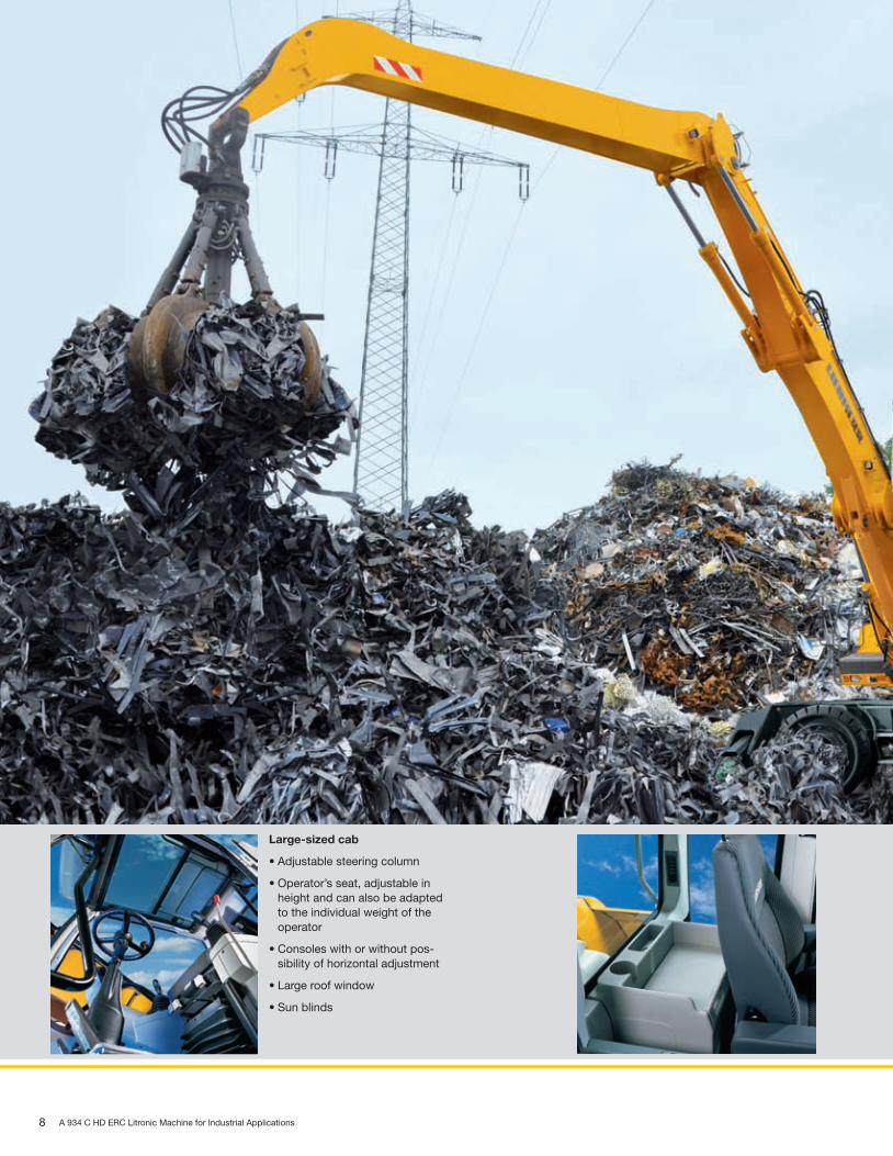
Large-sized cab
•Adjustablesteeringcolumn
•Operator’sseat,adjustableinheight and can also be adapted to the individual weight of the operator
•Consoleswithorwithoutpos-sibility of horizontal adjustment
•Largeroofwindow
•Sunblinds
A934C_HD_ERC_US.indd 8 17.07.12 14:14

9A 934 C HD ERC Litronic Machine for Industrial Applications
ComfortThe excavator operator is provided with an ergonomically arranged working area within the Liebherr cabs. All switches and functions are logically laid out. The op-erator’s seat, steering column and controls can be individually adjusted to guar-antee comfortable working environment so the operator can maintain maximumproductivity for the entire shift.
Mobile comfortEasy access The operator has wide steps, ergonomically posi-
tioned handles and adjustable steering column to allow easy access into the Liebherr cab.
Optimum visibility Liebherr has designed a well thought out design for the upper carriage. The cab features large glass panels and rounded edges to increase overall vis-ibility and guarantees a safe overview of the entire working area.
Pleasant surroundings Reduced engine speed together with elaborate sound insulation, as well as optimized hydraulic components, allow a comfortable noise level both inside and out. The noise level is comparable with that of modern cars.
Maintenance featuresSimple maintenance The Liebherr excavators come standard with a semi-
automatic lubrication system for the boom, stick at-tachments as well as the slewing gear.
Ease of operation A shut-off valve, fitted to the hydraulic tank as standard, disconnects the system and guarantees ease of maintenance to the hydraulic system.
Easy access Large, lockable maintenance doors allow easy and safe access to all maintenance points.
Fully-automatic air-conditioning system
•Theair-conditioningsystem,fitted as standard, offers the same comfort as that of a regular car
•Twosensorsforprecisetemperature regulation
•Ventilationflapsarecontrolledviakeys
•Defrostfunctionforquickdehumidifying/ defrosting of the windshield
Storage compartment –Everything has its place
•Amplestoragespacefora commercially-approved cooler box behind the operator’s seat
•Drinksholderandstorage compartment in operator’s cab
•Largestorageboxbehind the operator’s cab
•Twostandardtoolboxesin the undercarriage
A934C_HD_ERC_US.indd 9 17.07.12 14:14
10 A 934 C HD ERC Litronic Machine for Industrial Applications
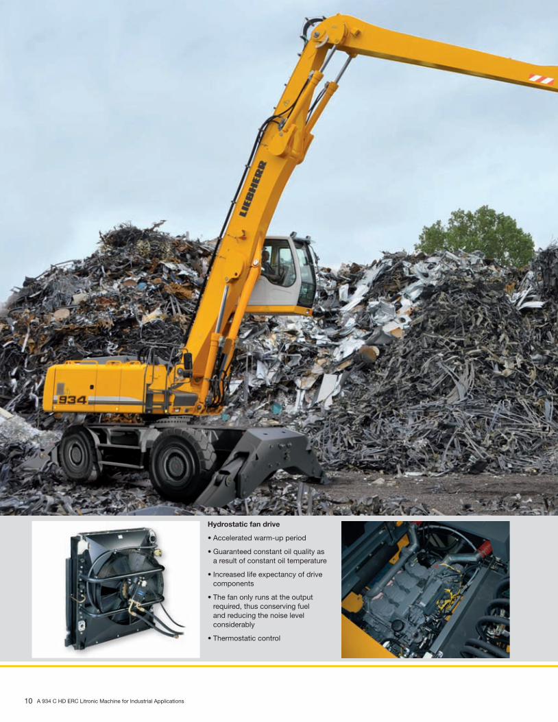
Hydrostatic fan drive
•Acceleratedwarm-upperiod
•Guaranteedconstantoilqualityasa result of constant oil temperature
•Increasedlifeexpectancyofdrivecomponents
•Thefanonlyrunsattheoutput required, thus conserving fuel and reducing the noise level considerably
•Thermostaticcontrol
A934C_HD_ERC_US.indd 10 17.07.12 14:14

11A 934 C HD ERC Litronic Machine for Industrial Applications
Economy
Service oriented
•Engineservicepoints-suchasthefilter or capacity displays - easily to access and reach via a catwalk
•Themagnetbarinthehydraulicoiltank acts as a service indicator and increases the service life of the oil
•Liebherrsemi-automaticcentrallubri-cating systems for the slewing gear and main attachment components fitted as standard for quick and tar-geted maintenance
A wide range
•Modularquickconnectionsystem
•Liebherrmechanicalandhydraulicquick connection for efficient chang-ing of working tools
•ComprehensiveLiebherr grab program
•WiderangeofLiebherrgrabs for different applications
Liebherr offers a wide range of Material Handlers models to maximize productivity in any application. Easy access to components and service points on the Liebherr Material Handlers allow for quick maintenance and minimal downtime reducing operating costs and maximizing production.
Low operating costsLiebherr engine Full engine power available even at low speeds. This
means that unrestricted power is available when it is really required, providing high levels of productivity and low fuel consumption.
Automatic engine idle
A great feature of the Liebherr material handler is the Auto En-gine Idle. The machine will automatically idle the engine if a hydraulic or engine function is not used over a period of time. The joysticks contain a proximity switch that once the operator is range of the joystick the engine will automatically return to operating RPM.
Intelligent hydraulicmanagement
The state-of-the-art hydraulic system allows conversion of the maximum engine output into high forceor speed, as required.
Hydraulically- adjustable cab
The hydraulically-adjustable cab allows the driver to op-timise his field of view to increase material-handling per-formance. Especially important when working with ships, barges or transloading material from trucks or railcars to maximize point of site to the working area.
Investment for the futureExtensive service offer
Our service personnel is trained directly at the manufacturing plants and endorsed by our tight-knit network of dealers.
High resale values Liebherr Material Handlers are designed with the highest grade materials possible providing the highest quality, with best fuel economy. When time comes to exchange for the next Liebherr, rest assured that a Liebherr Material Handler commands the best residual value in the Material Handling Industry.
ERC System The ERC System supports the equipment when lifting. This means that engine speeds can be lower, while at the same time smaller lifting cylinders can be fitted. That in turn sub-stantially reduces the machine’s fuel consumption, and leads to even greater economy.
A934C_HD_ERC_US.indd 11 17.07.12 14:14
12 A 934 C HD ERC Litronic Machine for Industrial Applications
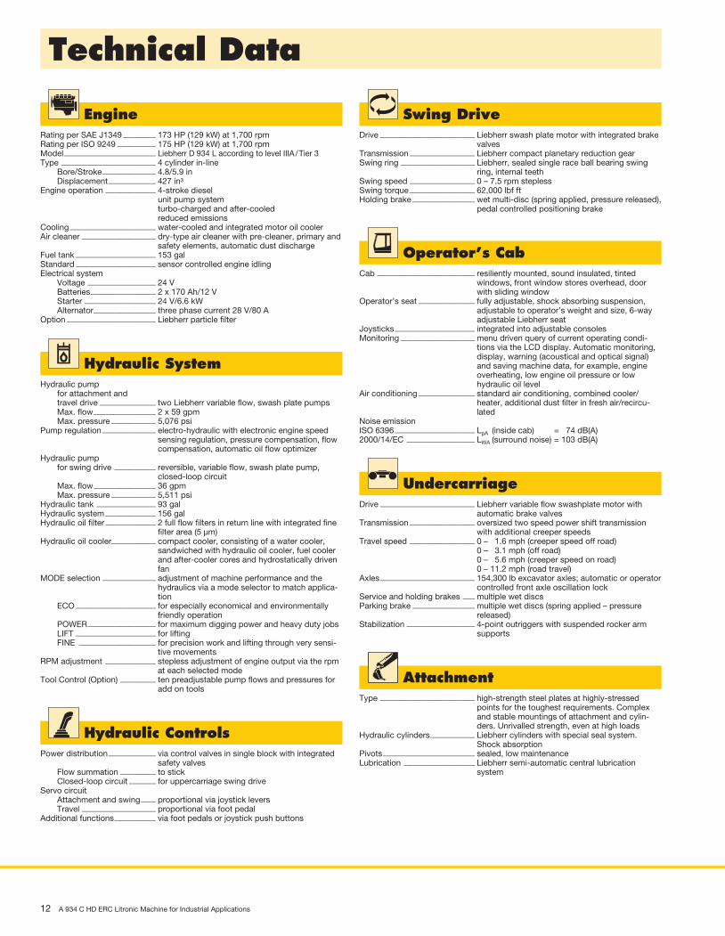
Technical Data
UndercarriageDrive �������������������������������� Liebherr variable flow swashplate motor with
automatic brake valvesTransmission ���������������������� oversized two speed power shift trans mission
with additional creeper speedsTravel speed ���������������������� 0 – 1.6 mph (creeper speed off road)
0 – 3.1 mph (off road) 0 – 5.6 mph (creeper speed on road) 0 – 11.2 mph (road travel)
Axles �������������������������������� 154,300 lb excavator axles; automatic or operator controlled front axle oscillation lock
Service and holding brakes ���� multiple wet discsParking brake ��������������������� multiple wet discs (spring applied – pressure
released)Stabilization ����������������������� 4-point outriggers with suspended rocker arm
supports
AttachmentType �������������������������������� high-strength steel plates at highly- stressed
points for the toughest requirements. Complex and stable mountings of attachment and cylin-ders. Unrivalled strength, even at high loads
Hydraulic cylinders ��������������� Liebherr cylinders with special seal system. Shock absorption
Pivots ������������������������������� sealed, low maintenanceLubrication ������������������������ Liebherr semi-automatic central lubrication
system
EngineRating per SAE J1349 ����������� 173 HP (129 kW) at 1,700 rpmRating per ISO 9249 ������������� 175 HP (129 kW) at 1,700 rpmModel ������������������������������� Liebherr D 934 L according to level IIIA / Tier 3Type �������������������������������� 4 cylinder in-line Bore/Stroke ������������������ 4.8/5.9 in Displacement ���������������� 427 in3
Engine operation ����������������� 4-stroke dieselunit pump system turbo-charged and after-cooled reduced emissions
Cooling ����������������������������� water-cooled and integrated motor oil coolerAir cleaner ������������������������� dry-type air cleaner with pre-cleaner, primary and
safety elements, automatic dust dischargeFuel tank ��������������������������� 153 galStandard ��������������������������� sensor controlled engine idlingElectrical system Voltage ����������������������� 24 V Batteries ���������������������� 2 x 170 Ah/12 V Starter ������������������������ 24 V/6.6 kW Alternator ��������������������� three phase current 28 V/80 AOption ������������������������������ Liebherr particle filter
Hydraulic SystemHydraulic pump for attachment and travel drive ������������������� two Liebherr variable flow, swash plate pumps Max. flow ��������������������� 2 x 59 gpm Max. pressure ��������������� 5,076 psiPump regulation ������������������ electro-hydraulic with electronic engine speed
sensing regulation, pressure compensation, flow compensation, automatic oil flow optimizer
Hydraulic pump for swing drive �������������� reversible, variable flow, swash plate pump,
closed-loop circuit Max. flow ��������������������� 36 gpm Max. pressure ��������������� 5,511 psiHydraulic tank �������������������� 93 galHydraulic system ����������������� 156 galHydraulic oil filter ����������������� 2 full flow filters in return line with inte grated fine
filter area (5 µm)Hydraulic oil cooler��������������� compact cooler, consisting of a water cooler,
sandwiched with hydraulic oil cooler, fuel cooler and after-cooler cores and hydrostatically driven fan
MODE selection ������������������ adjustment of machine performance and the hydraulics via a mode selector to match applica-tion
ECO ��������������������������� for especially economical and environ mentally friendly operation
POWER ����������������������� for maximum digging power and heavy duty jobs LIFT ��������������������������� for lifting FINE �������������������������� for precision work and lifting through very sensi-
tive movementsRPM adjustment ����������������� stepless adjustment of engine output via the rpm
at each selected modeTool Control (Option) ������������ ten preadjustable pump flows and pres sures for
add on tools
Hydraulic ControlsPower distribution ���������������� via control valves in single block with integrated
safety valves Flow summation ������������ to stick Closed-loop circuit ��������� for uppercarriage swing driveServo circuit Attachment and swing ����� proportional via joystick levers Travel ������������������������� proportional via foot pedalAdditional functions �������������� via foot pedals or joystick push buttons
Swing DriveDrive �������������������������������� Liebherr swash plate motor with integrated brake
valvesTransmission ���������������������� Liebherr compact planetary reduction gearSwing ring ������������������������� Liebherr, sealed single race ball bearing swing
ring, internal teethSwing speed ���������������������� 0 – 7.5 rpm steplessSwing torque ���������������������� 62,000 lbf ftHolding brake ��������������������� wet multi-disc (spring applied, pressure released),
pedal controlled positioning brake
Operator’s CabCab ��������������������������������� resiliently mounted, sound insulated, tinted
windows, front window stores overhead, door with sliding window
Operator’s seat ������������������� fully adjustable, shock absorbing suspen sion, adjustable to operator’s weight and size, 6-way adjustable Liebherr seat
Joysticks ��������������������������� integrated into adjustable consolesMonitoring ������������������������� menu driven query of current operating condi-
tions via the LCD display. Automatic monitoring, display, warning (acoustical and optical signal) and saving machine data, for example, engine overheating, low engine oil pressure or low hydraulic oil level
Air conditioning ������������������� standard air conditioning, combined cooler/ heater, additional dust filter in fresh air/recircu-lated
Noise emissionISO 6396 ��������������������������� LpA (inside cab) = 74 dB(A)2000/14/EC ����������������������� LWA (surround noise) = 103 dB(A)

A 934 C HD ERC Litronic Machine for Industrial Applications 13
Dimensions
F
G
P
Hydraulic Cab Elevation ft inA 10’ A1) 9’10”A1 10’ 8”A11) 11’ 2”B 10’ 6”B1 17’ 3”C 11’10”D 10’ 7”E 10’ 7”H 10’ K 5’ 6”L 10’ 6”M 5’ 3”Q 1’ 3’T1 5’ T4 4’ 7”U4 20’ 1”Z 20’ 8”
1) Rigid cab elevationE = Tail radius
Tires 20.5-25
Industrial-Type Straight Mono Boom 24’11” and Industrial Stick ft in 19’ 8”V ft in 22’ 2”W ft in 10’10”X ft in 37’ 1”
Industrial-Type Straight Mono Boom 28’3” and Industrial Stick ft in 19’ 8” 24’ 7”V ft in 24’11” 21’ 4”W ft in 10’ 13’11”X ft in 40’ 4” 40’
Industrial-Type Straight Mono Boom 31’6” and Industrial Stick ft in 24’ 7”V ft in 24’ 3”W ft in 13’ 1”X ft in 43’ 6”
Industrial Stick ft in 16’ 5” 19’ 8” 24’ 7”F ft in 17’ 7” 20’10” 25’ 9”G ft in 3’11” 4’ 1” 4’ 1”P ft in 3’ 5” 3’ 5” 3’ 5”
Dimensions are with attachment over steering axle
A1
A
C
Q
B
B1
D
K
HW
T1T4 M
L
U4
Z
V
X
E
14 A 934 C HD ERC Litronic Machine for Industrial Applications
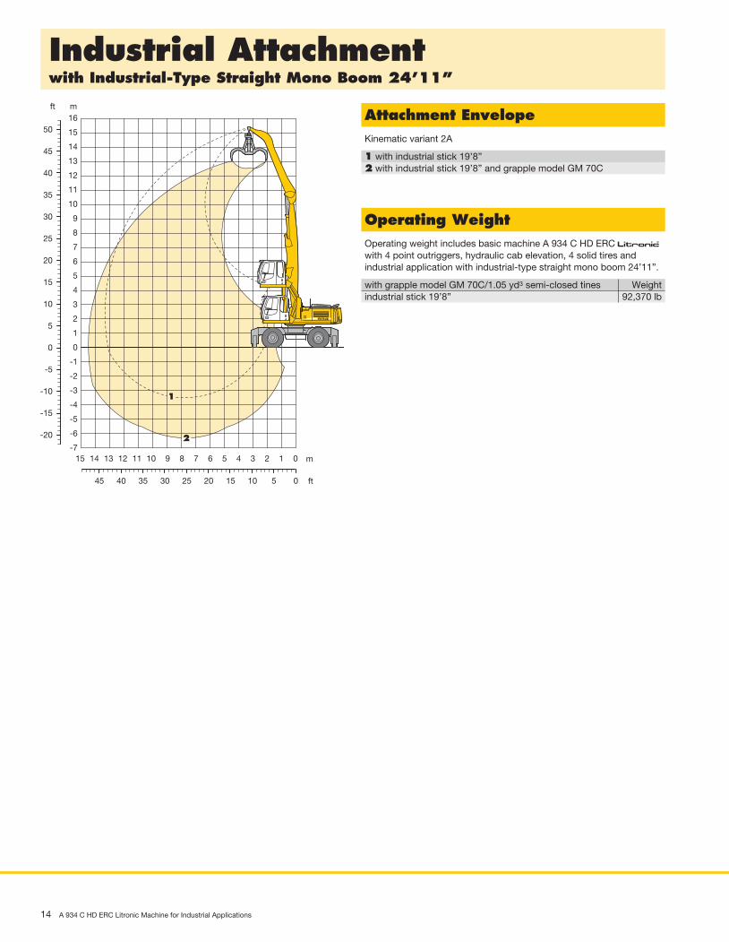
Industrial Attachmentwith Industrial-Type Straight Mono Boom 24’11”
Attachment EnvelopeKinematic variant 2A
1 with industrial stick 19’8”2 with industrial stick 19’8” and grapple model GM 70C
Operating WeightOperating weight includes basic machine A 934 C HD ERC litronic̀ with 4 point outriggers, hydraulic cab elevation, 4 solid tires and industrial application with industrial-type straight mono boom 24’11”.
with grapple model GM 70C/1.05 yd3 semi-closed tines Weightindustrial stick 19’8” 92,370 lb
ft m
ft
m
16
15
14
13
12
11
10
9
8
7
6
5
4
3
2
1
0
-1
-2
-3
-4
-5
-6
-7
50
40
45
35
30
25
20
15
10
5
0
1415 13 12 11 10 9 8 7 6 5 4 3 2 1 0
4045 35 30 25 20 15 10 5 0
-5
-10
-15
-20
1
2
A 934 C HD ERC Litronic Machine for Industrial Applications 15
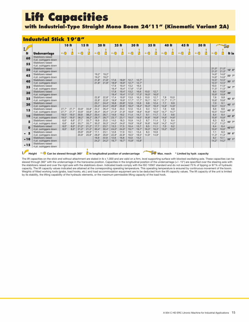
Lift Capacitieswith Industrial-Type Straight Mono Boom 24’11” (Kinematic Variant 2A)
Height Can be slewed through 360° In longitudinal position of undercarriage Max. reach * Limited by hydr. capacity
The lift capacities on the stick end without attachment are stated in lb x 1,000 and are valid on a firm, level supporting surface with blocked oscillat ing axle. These capacities can be slewed through 360° with the undercarriage in the transverse position. Capacities in the longitudinal position of the undercarriage (+/– 15°) are specified over the steering axle with the stabilizers raised and over the rigid axle with the stabilizers down. Indicated loads comply with the ISO 10567 standard and do not exceed 75 % of tipping or 87 % of hydraulic capacity. The lift capacity values indicated are attained at the corresponding operating temperature. This operating temperature is ensured by continuous movement of the boom. Weights of fitted working tools (grabs, load hooks, etc.) and load accommodation equipment are to be deducted from the lift capacity values. The lift capacity of the unit is limited by its stability, the lifting capability of the hydraulic elements, or the maximum permissible lifting capacity of the load hook.
Industrial Stick 19’8” 10 ft 15 ft 20 ft 25 ft 30 ft 35 ft 40 ft 45 ft 50 ft
ft Undercarriage ft in Stabilizers raised 60 4 pt. outriggers down Stabilizers raised 55 4 pt. outriggers down Stabilizers raised 50 4 pt. outriggers down Stabilizers raised 45 4 pt. outriggers down Stabilizers raised 40 4 pt. outriggers down Stabilizers raised 35 4 pt. outriggers down Stabilizers raised 30 4 pt. outriggers down Stabilizers raised 25 4 pt. outriggers down Stabilizers raised 20 4 pt. outriggers down Stabilizers raised 15 4 pt. outriggers down Stabilizers raised 10 4 pt. outriggers down Stabilizers raised 5 4 pt. outriggers down Stabilizers raised 0 4 pt. outriggers down Stabilizers raised – 5 4 pt. outriggers down Stabilizers raised – 10 4 pt. outriggers down Stabilizers raised – 15 4 pt. outriggers down
21,0* 21,0* 21,0* 21,0*
12’ 8”
19,2* 19,2* 14,6* 14,6* 19,2* 19,2* 14,6* 14,6*
23’ 7”
21,8* 21,8* 17,6 18,9* 12,7 12,7* 12,5* 12,5* 21,8* 21,8* 18,9* 18,9* 12,7* 12,7* 12,5* 12,5*
30’ 1”
17,9 19,4* 13,2 16,5 10,0 11,5* 19,4* 19,4* 17,6* 17,6* 11,5* 11,5*
34’ 7”
17,8 19,4* 13,2 16,6 10,0 12,7 8,5 10,9* 19,4* 19,4* 17,5* 17,5* 16,0* 16,0* 10,9* 10,9*
38’
22,8* 22,8* 17,4 19,9* 13,0 16,3 10,0 12,7 7,8 10,0 7,6 9,8 22,8* 22,8* 19,9* 19,9* 17,7* 17,7* 16,1* 16,1* 11,7* 11,7* 10,6* 10,6*
40’ 5”
23,7 24,4* 16,8 20,8* 12,6 15,9 9,8 12,4 7,7 9,9 7,0 9,1 24,4* 24,4* 20,8* 20,8* 18,2* 18,2* 16,3* 16,3* 14,6* 14,6* 10,5* 10,5*
42’ 1”
27,7* 27,7* 33,8* 33,8* 22,2 26,4* 15,9 20,3 12,0 15,4 9,4 12,1 7,6 9,8 6,6 8,6 27,7* 27,7* 33,8* 33,8* 26,4* 26,4* 21,9* 21,9* 18,9* 18,9* 16,6* 16,6* 14,7* 14,7* 10,5* 10,5*
43’ 3”
19,5* 19,5* 30,8 38,2* 20,4 26,7 14,9 19,2 11,4 14,7 9,1 11,7 7,4 9,6 6,4 8,4 19,5* 19,5* 38,2* 38,2* 28,7* 28,7* 23,1* 23,1* 19,5* 19,5* 16,8* 16,8* 14,6* 14,6* 10,8* 10,8*
43’ 8”
6,6* 6,6* 27,7 33,7* 18,9 25,0 14,0 18,3 10,9 14,2 8,7 11,4 7,2 9,4 6,3 8,3 6,6* 6,6* 33,7* 33,7* 30,3* 30,3* 24,0* 24,0* 19,9* 19,9* 16,8* 16,8* 14,2* 14,2* 11,2* 11,2*
43’ 7”
8,0* 8,0* 21,2* 21,2* 17,7 23,7 13,3 17,5 10,4 13,7 8,5 11,1 7,0 9,2 6,4 8,4 8,0* 8,0* 21,2* 21,2* 30,4* 30,4* 24,0* 24,0* 19,7* 19,7* 16,3* 16,3* 13,2* 13,2* 10,6* 10,6*
42’11”
20,8* 20,8* 17,1 23,1 12,8 17,0 10,1 13,4 8,3 10,9 7,1 9,3 20,8* 20,8* 28,6* 28,6* 22,8* 22,8* 18,5* 18,5* 14,9* 14,9* 11,3* 11,3*
39’ 8”
16,9 22,9 12,6 16,8 10,0 13,2 9,2 12,1 24,2* 24,2* 19,7* 19,7* 15,8* 15,8* 14,2* 14,2*
32’ 1”

16 A 934 C HD ERC Litronic Machine for Industrial Applications
Industrial Attachmentwith Industrial-Type Straight Mono Boom 28’3”
Attachment EnvelopeKinematic variant 2A
1 with industrial stick 19’8”2 with industrial stick 24’7”3 with industrial stick 19’8” and grapple model GM 70C4 with industrial stick 24’7” and grapple model GM 70C
Operating WeightOperating weight includes basic machine A 934 C HD ERC litronic̀ with 4 point outriggers, hydraulic cab elevation, 4 solid tires and industrial application with industrial-type straight mono boom 28’3”.
with grapple model GM 70C/1.05 yd3 semi-closed tines Weightindustrial stick 19’8” 93,040 lbindustrial stick 24’7” 93,670 lb
ft m
ft
m
16
17
18
15
14
13
12
11
10
9
8
7
6
5
4
3
2
1
0 0
-1
-2
-3
-4
-5
-6
-8
-7
50
55
40
45
35
30
25
20
15
10
5
14151617 13 12 11 10 9 8 7 6 5 4 3 2 1 0
4050 4555 35 30 25 20 15 10 5 0
-5
-10
-15
-20
-25
1
2
3
4
A 934 C HD ERC Litronic Machine for Industrial Applications 17
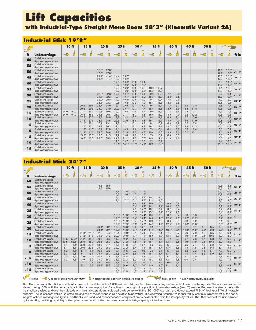
Lift Capacitieswith Industrial-Type Straight Mono Boom 28’3” (Kinematic Variant 2A)
Height Can be slewed through 360° In longitudinal position of undercarriage Max. reach * Limited by hydr. capacity
The lift capacities on the stick end without attachment are stated in lb x 1,000 and are valid on a firm, level supporting surface with blocked oscillat ing axle. These capacities can be slewed through 360° with the undercarriage in the transverse position. Capacities in the longitudinal position of the undercarriage (+/– 15°) are specified over the steering axle with the stabilizers raised and over the rigid axle with the stabilizers down. Indicated loads comply with the ISO 10567 standard and do not exceed 75 % of tipping or 87 % of hydraulic capacity. The lift capacity values indicated are attained at the corresponding operating temperature. This operating temperature is ensured by continuous movement of the boom. Weights of fitted working tools (grabs, load hooks, etc.) and load accommodation equipment are to be deducted from the lift capacity values. The lift capacity of the unit is limited by its stability, the lifting capability of the hydraulic elements, or the maximum permissible lifting capacity of the load hook.
Industrial Stick 19’8” 10 ft 15 ft 20 ft 25 ft 30 ft 35 ft 40 ft 45 ft 50 ft
ft Undercarriage ft in Stabilizers raised 60 4 pt. outriggers down Stabilizers raised 55 4 pt. outriggers down Stabilizers raised 50 4 pt. outriggers down Stabilizers raised 45 4 pt. outriggers down Stabilizers raised 40 4 pt. outriggers down Stabilizers raised 35 4 pt. outriggers down Stabilizers raised 30 4 pt. outriggers down Stabilizers raised 25 4 pt. outriggers down Stabilizers raised 20 4 pt. outriggers down Stabilizers raised 15 4 pt. outriggers down Stabilizers raised 10 4 pt. outriggers down Stabilizers raised 5 4 pt. outriggers down Stabilizers raised 0 4 pt. outriggers down Stabilizers raised – 5 4 pt. outriggers down Stabilizers raised – 10 4 pt. outriggers down Stabilizers raised – 15 4 pt. outriggers down
Industrial Stick 24’7” 10 ft 15 ft 20 ft 25 ft 30 ft 35 ft 40 ft 45 ft 50 ft
ft Undercarriage ft in Stabilizers raised 60 4 pt. outriggers down Stabilizers raised 55 4 pt. outriggers down Stabilizers raised 50 4 pt. outriggers down Stabilizers raised 45 4 pt. outriggers down Stabilizers raised 40 4 pt. outriggers down Stabilizers raised 35 4 pt. outriggers down Stabilizers raised 30 4 pt. outriggers down Stabilizers raised 25 4 pt. outriggers down Stabilizers raised 20 4 pt. outriggers down Stabilizers raised 15 4 pt. outriggers down Stabilizers raised 10 4 pt. outriggers down Stabilizers raised 5 4 pt. outriggers down Stabilizers raised 0 4 pt. outriggers down Stabilizers raised – 5 4 pt. outriggers down Stabilizers raised – 10 4 pt. outriggers down Stabilizers raised – 15 4 pt. outriggers down
17,8* 17,8* 16,0* 16,0* 17,8* 17,8* 16,0* 16,0*
21’ 4”
21,4* 21,4* 17,4 18,2* 13,1 13,2* 21,4* 21,4* 18,2* 18,2* 13,2* 13,2*
29’ 2”
17,8 19,0* 13,0 16,4 9,9 11,9* 19,0* 19,0* 17,0* 17,0* 11,9* 11,9*
34’ 7”
17,9 18,9* 13,2 16,6 10,0 12,7 8,1 10,5 18,9* 18,9* 16,8* 16,8* 15,2* 15,2* 11,2* 11,2*
38’ 7”
22,3* 22,3* 17,6 19,1* 13,0 16,4 9,9 12,6 7,7 9,9 7,0 9,1 22,3* 22,3* 19,1* 19,1* 16,9* 16,9* 15,2* 15,2* 13,8* 13,8* 10,7* 10,7*
41’ 7”
23,3* 23,3* 17,0 19,8* 12,6 16,0 9,7 12,4 7,6 9,9 6,3 8,3 23,3* 23,3* 19,8* 19,8* 17,2* 17,2* 15,3* 15,3* 13,8* 13,8* 10,5* 10,5*
43’11”
29,6* 29,6* 22,7 24,9* 16,1 20,5 12,1 15,4 9,4 12,1 7,4 9,7 5,9 7,8 5,8 7,7 29,6* 29,6* 24,9* 24,9* 20,7* 20,7* 17,7* 17,7* 15,6* 15,6* 13,9* 13,9* 11,8* 11,8* 10,5* 10,5*
45’ 5”
54,0* 54,0* 31,7 35,5* 20,8 26,8* 15,0 19,4 11,4 14,7 9,0 11,6 7,2 9,4 5,8 7,7 5,5 7,3 54,0* 54,0* 35,5* 35,5* 26,8* 26,8* 21,7* 21,7* 18,3* 18,3* 15,9* 15,9* 14,0* 14,0* 12,2* 12,2* 10,6* 10,6*
46’ 5”
27,5* 27,5* 18,8 24,9 13,8 18,2 10,7 14,0 8,5 11,2 6,9 9,1 5,7 7,6 5,3 7,1 27,5* 27,5* 28,5* 28,5* 22,6* 22,6* 18,8* 18,8* 16,1* 16,1* 14,0* 14,0* 11,9* 11,9* 10,8* 10,8*
46’10”
12,1* 12,1* 17,1 23,1 12,8 17,1 10,1 13,3 8,1 10,7 6,6 8,9 5,5 7,4 5,2 7,0 12,1* 12,1* 29,3* 29,3* 23,1* 23,1* 19,1* 19,1* 16,1* 16,1* 13,7* 13,7* 11,3* 11,3* 10,1* 10,1*
46’ 9”
11,5* 11,5* 16,1 22,0 12,1 16,3 9,6 12,8 7,8 10,4 6,4 8,6 5,5 7,4 5,3 7,1 11,5* 11,5* 28,6* 28,6* 22,8* 22,8* 18,7* 18,7* 15,6* 15,6* 13,0* 13,0* 10,1* 10,1* 9,1* 9,1*
46’ 1”
13,5* 13,5* 15,6 21,5 11,7 15,8 9,2 12,5 7,6 10,2 6,3 8,5 5,8 7,8 13,5* 13,5* 25,9* 25,9* 21,2* 21,2* 17,5* 17,5* 14,4* 14,4* 11,6* 11,6* 9,6* 9,6*
42’11”
11,5 15,7 9,1 12,3 7,5 10,1 7,4 10,0 18,1* 18,1* 15,1* 15,1* 12,2* 12,2* 11,9* 11,9*
35’ 4”
15,6* 15,6* 13,5* 13,5* 15,6* 15,6* 13,5* 13,5*
22’ 1”
15,6* 15,6* 11,7* 11,7* 10,9* 10,9* 15,6* 15,6* 11,7* 11,7* 10,9* 10,9*
30’ 7”
17,1* 17,1* 13,7 15,1* 10,2 11,5* 9,3 9,6* 17,1* 17,1* 15,1* 15,1* 11,5* 11,5* 9,6* 9,6*
36’ 6”
14,0 15,4* 10,6 13,3 8,0 10,2 7,5 8,9* 15,4* 15,4* 14,1* 14,1* 10,3* 10,3* 8,9* 8,9*
40’11”
14,1 15,3* 10,7 13,4 8,2 10,4 6,4 8,4 15,3* 15,3* 13,9* 13,9* 12,8* 12,8* 8,4* 8,4*
44’ 5”
17,3* 17,3* 13,9 15,4* 10,5 13,3 8,2 10,4 6,3 8,3 5,7 7,5 17,3* 17,3* 15,4* 15,4* 14,0* 14,0* 12,8* 12,8* 11,2* 11,2* 8,2* 8,2*
47’
17,9* 17,9* 13,4 15,8* 10,3 13,0 8,0 10,3 6,3 8,2 5,1 6,9 17,9* 17,9* 15,8* 15,8* 14,2* 14,2* 12,9* 12,9* 11,8* 11,8* 8,0* 8,0*
49’
20,1* 20,1* 17,3 18,8* 12,8 16,2 9,9 12,6 7,7 10,0 6,1 8,1 4,9 6,5 4,8 6,4 20,1* 20,1* 18,8* 18,8* 16,4* 16,4* 14,6* 14,6* 13,1* 13,1* 11,9* 11,9* 8,9* 8,9* 8,0* 8,0*
50’ 5”
21,3* 21,3* 22,8 24,2* 16,1 20,0* 12,1 15,4 9,4 12,1 7,4 9,7 5,9 7,9 4,8 6,5 4,5 6,1 21,3* 21,3* 24,2* 24,2* 20,0* 20,0* 17,1* 17,1* 15,0* 15,0* 13,3* 13,3* 11,9* 11,9* 10,5* 10,5* 8,0* 8,0*
51’ 4”
53,5* 53,5* 31,2 35,0* 20,5 26,3* 14,8 19,2 11,2 14,5 8,8 11,5 7,0 9,3 5,7 7,6 4,7 6,3 4,4 6,0 53,5* 53,5* 35,0* 35,0* 26,3* 26,3* 21,2* 21,2* 17,8* 17,8* 15,4* 15,4* 13,5* 13,5* 11,9* 11,9* 10,3* 10,3* 8,2* 8,2*
51’ 8”
5,1* 5,1* 26,9 29,6* 18,3 24,4 13,5 17,8 10,4 13,7 8,2 10,9 6,7 8,9 5,5 7,4 4,6 6,2 4,3 5,9 5,1* 5,1* 29,6* 29,6* 28,0* 28,0* 22,2* 22,2* 18,4* 18,4* 15,7* 15,7* 13,6* 13,6* 11,8* 11,8* 9,8* 9,8* 8,4* 8,4*
51’ 7”
5,3* 5,3* 15,1* 15,1* 16,6 22,6 12,4 16,6 9,7 12,9 7,8 10,4 6,4 8,6 5,3 7,2 4,5 6,1 4,3 6,0 5,3* 5,3* 15,1* 15,1* 28,7* 28,7* 22,6* 22,6* 18,6* 18,6* 15,7* 15,7* 13,4* 13,4* 11,4* 11,4* 8,9* 8,9* 8,1* 8,1*
51’
7,2* 7,2* 13,9* 13,9* 15,5 21,4 11,6 15,8 9,1 12,4 7,4 10,0 6,1 8,3 5,1 7,0 4,5 6,2 7,2* 7,2* 13,9* 13,9* 28,0* 28,0* 22,2* 22,2* 18,2* 18,2* 15,2* 15,2* 12,8* 12,8* 10,4* 10,4* 7,9* 7,9*
49’ 2”
15,1* 15,1* 15,0 20,8 11,2 15,3 8,8 12,0 7,2 9,8 6,0 8,2 5,1 7,0 15,1* 15,1* 25,5* 25,5* 20,6* 20,6* 17,0* 17,0* 14,0* 14,0* 11,4* 11,4* 8,8* 8,8*
44’ 9”
11,0 15,2 8,7 11,9 7,1 9,7 6,8 9,4 17,5* 17,5* 14,5* 14,5* 11,8* 11,8* 11,3* 11,3*
36’
18 A 934 C HD ERC Litronic Machine for Industrial Applications
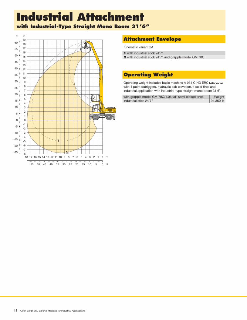
Industrial Attachmentwith Industrial-Type Straight Mono Boom 31’6”
Attachment EnvelopeKinematic variant 2A
1 with industrial stick 24’7”2 with industrial stick 24’7” and grapple model GM 70C
Operating WeightOperating weight includes basic machine A 934 C HD ERC litronic̀ with 4 point outriggers, hydraulic cab elevation, 4 solid tires and industrial application with industrial-type straight mono boom 31’6”.
with grapple model GM 70C/1.05 yd3 semi-closed tines Weightindustrial stick 24’7” 94,360 lb
ft m
ft
m
16
17
18
15
14
13
12
11
10
9
8
7
6
5
4
3
2
1
0 0
-1
-2
-3
-4
-5
-6
-8
-7
50
55
1960
40
45
35
30
25
20
15
10
5
1415161718 13 12 11 10 9 8 7 6 5 4 3 2 1 0
4050 4555 35 30 25 20 15 10 5 0
-5
-10
-15
-20
-25
11
2

A 934 C HD ERC Litronic Machine for Industrial Applications 19
Lift Capacitieswith Industrial-Type Straight Mono Boom 31’6” (Kinematic Variant 2A)
Height Can be slewed through 360° In longitudinal position of undercarriage Max. reach * Limited by hydr. capacity
The lift capacities on the stick end without attachment are stated in lb x 1,000 and are valid on a firm, level supporting surface with blocked oscillat ing axle. These capacities can be slewed through 360° with the undercarriage in the transverse position. Capacities in the longitudinal position of the undercarriage (+/– 15°) are specified over the steering axle with the stabilizers raised and over the rigid axle with the stabilizers down. Indicated loads comply with the ISO 10567 standard and do not exceed 75 % of tipping or 87 % of hydraulic capacity. The lift capacity values indicated are attained at the corresponding operating temperature. This operating temperature is ensured by continuous movement of the boom. Weights of fitted working tools (grabs, load hooks, etc.) and load accommodation equipment are to be deducted from the lift capacity values. The lift capacity of the unit is limited by its stability, the lifting capability of the hydraulic elements, or the maximum permissible lifting capacity of the load hook.
Industrial Stick 24’7” 10 ft 15 ft 20 ft 25 ft 30 ft 35 ft 40 ft 45 ft 50 ft
ft Undercarriage ft in Stabilizers raised 60 4 pt. outriggers down Stabilizers raised 55 4 pt. outriggers down Stabilizers raised 50 4 pt. outriggers down Stabilizers raised 45 4 pt. outriggers down Stabilizers raised 40 4 pt. outriggers down Stabilizers raised 35 4 pt. outriggers down Stabilizers raised 30 4 pt. outriggers down Stabilizers raised 25 4 pt. outriggers down Stabilizers raised 20 4 pt. outriggers down Stabilizers raised 15 4 pt. outriggers down Stabilizers raised 10 4 pt. outriggers down Stabilizers raised 5 4 pt. outriggers down Stabilizers raised 0 4 pt. outriggers down Stabilizers raised – 5 4 pt. outriggers down Stabilizers raised – 10 4 pt. outriggers down Stabilizers raised – 15 4 pt. outriggers down
15,4* 15,4* 15,4* 15,4*
18’ 5”
14,9* 14,9* 11,6* 11,6* 14,9* 14,9* 11,6* 11,6*
28’11”
16,8* 16,8* 13,5 14,7* 9,9 11,0* 9,4 10,1* 16,8* 16,8* 14,7* 14,7* 11,0* 11,0* 10,1* 10,1*
35’ 9”
14,0 15,1* 10,5 13,2 7,8 10,1 7,4 9,2* 15,1* 15,1* 13,6* 13,6* 10,4* 10,4* 9,2* 9,2*
40’11”
14,1 15,0* 10,6 13,4 8,1 10,4 6,1 8,0 15,0* 15,0* 13,4* 13,4* 12,2* 12,2* 8,6* 8,6*
44’11”
14,0 15,0* 10,6 13,3 8,1 10,4 6,2 8,2 5,2 7,0 15,0* 15,0* 13,4* 13,4* 12,2* 12,2* 11,2* 11,2* 8,3* 8,3*
48’ 1”
17,5* 17,5* 13,6 15,3* 10,3 13,1 8,0 10,3 6,2 8,2 4,8 6,5 4,6 6,3 17,5* 17,5* 15,3* 15,3* 13,6* 13,6* 12,2* 12,2* 11,1* 11,1* 9,0* 9,0* 8,1* 8,1*
50’ 6”
17,7 18,1* 13,0 15,7* 9,9 12,7 7,7 10,0 6,1 8,0 4,7 6,4 4,2 5,8 18,1* 18,1* 15,7* 15,7* 13,8* 13,8* 12,4* 12,4* 11,2* 11,2* 10,1* 10,1* 8,0* 8,0*
52’ 5”
22,8* 22,8* 16,5 19,0* 12,2 15,6 9,4 12,1 7,4 9,6 5,8 7,8 4,6 6,3 3,9 5,4 22,8* 22,8* 19,0* 19,0* 16,2* 16,2* 14,1* 14,1* 12,6* 12,6* 11,3* 11,3* 10,1* 10,1* 8,0* 8,0*
53’ 8”
32,3* 32,3* 32,7* 32,7* 21,1 24,7* 15,1 19,5 11,3 14,7 8,8 11,5 7,0 9,2 5,6 7,5 4,5 6,2 3,6 5,2 32,3* 32,3* 32,7* 32,7* 24,7* 24,7* 19,9* 19,9* 16,8* 16,8* 14,5* 14,5* 12,7* 12,7* 11,3* 11,3* 10,1* 10,1* 8,0* 8,0*
54’ 7”
27,3 33,1* 18,5 24,7 13,5 17,9 10,3 13,7 8,1 10,8 6,5 8,7 5,3 7,2 4,3 6,0 3,5 5,0 33,1* 33,1* 26,3* 26,3* 20,9* 20,9* 17,3* 17,3* 14,8* 14,8* 12,9* 12,9* 11,3* 11,3* 9,9* 9,9* 8,2* 8,2*
54’11”
9,6* 9,6* 16,2 22,2 12,1 16,4 9,4 12,7 7,5 10,2 6,1 8,3 5,0 6,9 4,1 5,8 3,5 4,9 9,6* 9,6* 27,3* 27,3* 21,5* 21,5* 17,6* 17,6* 15,0* 15,0* 12,9* 12,9* 11,2* 11,2* 9,6* 9,6* 7,6* 7,6*
54’ 9”
2,6* 2,6* 8,1* 8,1* 14,6 20,5 11,0 15,2 8,7 11,9 7,0 9,6 5,7 7,9 4,7 6,6 4,0 5,6 3,5 5,0 2,6* 2,6* 8,1* 8,1* 21,5* 21,5* 21,5* 21,5* 17,6* 17,6* 14,8* 14,8* 12,7* 12,7* 10,9* 10,9* 9,1* 9,1* 7,0* 7,0*
54’ 4”
9,1* 9,1* 13,7 18,3* 10,3 14,4 8,1 11,3 6,6 9,2 5,5 7,6 4,6 6,5 3,9 5,6 3,6 5,2 9,1* 9,1* 18,3* 18,3* 20,6* 20,6* 17,0* 17,0* 14,3* 14,3* 12,1* 12,1* 10,2* 10,2* 8,1* 8,1* 6,7* 6,7*
52’ 6”
13,3 18,4* 9,9 14,0 7,8 11,0 6,4 9,0 5,3 7,5 4,5 6,4 4,1 5,8 18,4* 18,4* 18,8* 18,8* 15,7* 15,7* 13,1* 13,1* 11,0* 11,0* 8,9* 8,9* 7,4* 7,4*
48’ 1”
9,8 13,9 7,7 10,9 6,3 8,9 5,4 7,6 15,7* 15,7* 13,3* 13,3* 11,2* 11,2* 9,4* 9,4*
39’ 3”

20 A 934 C HD ERC Litronic Machine for Industrial Applications
Choice of Cab Elevation and Cab Protection
D1
B1C1
B2
D2
C2
E
D1
B1C1
B2
D2
C2
E
Hydraulic Cab Elevation (Parallelogram)B1 10’ 2”B2 18’ 4”C1 11’10”C2 20’ D1 4’ 6”D2 5’ 4”E 11’ 6”
The parallelogram cab raiser allows the operator to choose his field of view between dimensions B1 and B2. For a transport height lower than C1 the shell of the cab can be removed. The overall height is then E.As cab protection a front window screen can be installed.
Grille above Grilles in front
Hydraulic Cab Elevation (Parallelogram) + Intermediate Piece 1’2”B1 11’ 4”B2 22’ 6”C1 13’ C2 24’ 2”D1 7’10”D2 7’10”E 12’11”
The parallelogram cab raiser allows the operator to choose his field of view between dimensions B1 and B2. For a transport height lower than C1 the shell of the cab can be removed. The overall height is then E.As cab protection a front window screen can be installed.

Shells for Loose Material Clamshell Model GM 20B
A 934 C HD ERC Litronic Machine for Industrial Applications 21
Variety of Tools
Shells for loose material with cutting edge (without teeth)Cutting width of shells ft in 3’3” 3’11” 5’3”Capacity yd3 1.70 1.96 2.62For loose material, specific weight up to lb/yd3 2,530 2,530 2,530Weight lb 2,985 3,120 3,415
Multiple Tine Grapples open tines semi-closed tines closed tines
Grapple Model GM 64 Capacity yd3 0.52 0.78 0.52 0.78 0.52 0.78(4 tines) Weight lb 1,865 2,490 2,325 2,930 2,335 3,350Grapple Model GM 65 Capacity yd3 0.52 0.78 0.52 0.78 0.52 0.78(5 tines) Weight lb 2,535 2,710 2,835 3,120 2,920 3,350Grapple Model GM 69 Capacity yd3 1.05 1.44 1.05 1.44 1.05 1.44(4 tines) Weight lb 2,965 3,075 3,385 3,615 4,190 4,540Grapple Model GM 70C Capacity yd3 1.05 1.44 1.05 1.44 1.05 1.44(5 tines) Weight lb 3,275 3,505 3,760 4,100 4,300 4,400
Crane Hook with SuspensionMax. load lb 27,560Height with suspension ft in 3’1”Weight lb 210
Magnet Devices/Lifting MagnetsGenerator kW 13 20Electromagnets with SuspensionPower kW 8.5 10Diameter of magnet ft in 4’3” 4’7”Height with suspension ft in 3’7” 3’7”Weight lb 2,975 4,035

• = Standard, + = Option
Options and/or special attachments, supplied by vendors other than Liebherr, are only to be installed with the knowledge and approval of Liebherr in order to retain warranty.
Equipment
UndercarriageTwo circuit travel brake with accumulator •Travel motor protection +Outrigger cylinder rod guards +Creeper speed electrically switchable from cab •New tires •Service free parking brake •Independent outrigger control +Choice of tires +Auto check valve directly on each stabilizer cylinder •Proportional power steering •Customized colors +Two lockable storage boxes •Two-speed power shift transmission •
Operator’s CabStorage tray •Displays for engine operating condition •Mechanical hour meters, readable from outside the cab •Roof hatch •6-way adjustable seat •Airpressure operator seat with heating and head-rest +Seat and consoles independently adjustable •Extinguisher +Removable customized foot mat •Dome light •Hydraulic cab elevation +Rigid cab elevation +Cab heater with defroster •Coat hook •Air conditioning •Electric cooler +Steering wheel adjustable •Bullet proof window (fixed installation – can not be opened) +Stereo radio +Preparation for radio installation +Rain visor over front window opening •Beacon +Tinted windows •Door with sliding window •Optical warning if outriggers are not fully retracted +Auxiliary heating +Sun shade +Sun roller blind •Electronic theft protection +Wiper/washer •Cigarette lighter and ashtray •Additional flood lights +
UppercarriageElectric fuel tank filler pump +Maintenance-free swing brake lock •Handrails, non slip surfaces •Main switch for electric circuit •Engine hood with lift assistance •Pedal controlled positioning swing brake •Reverse travel warning system +Sound insulation •Customized colors +Maintenance-free HD-batteries •Lockable tool box •Tool kit •
HydraulicsHydraulic tank shut-off valve •Extra hydr. control for hydr. swivel +Pressure compensation •Hook up for pressure checks •Pressure storage for controlled lowering of attachments with engine turned off •Filter with partial micro filtration (5 µm) •Electronic pump regulation •Stepless mode system (ECO) •Flow compensation •Four mixed modes, can also be adjusted •Full flow micro filtration +Bio degradable hydraulic oil +Tool Control +Additional hydraulic circuits +
AttachmentFlood lights •ERC system •Hydr. lines for clam operation in sticks •Industrial stick with quick change system +Sealed pivots •Safety lift hook +Liebherr line of clams +Liebherr semi-automatic central lubrication system •Liebherr fully-automatic central lubrication system +Safety check valves on hoist cylinder •Safety check valves on stick cylinder •Hose quick connection •Customized colors +Special buckets and other tools +Overload warning device +Two way valves for bucket/clam use +Locking of connections for clam operation +Cylinders with shock absorber •
EngineTurbo charger •After-cooled •Sensor controlled engine idling •Liebherr particle filter +Unit pump system •Air filter with pre-cleaner main- and safety element •
All
illus
trat
ions
and
dat
a m
ay d
iffer
from
sta
ndar
d e
qui
pm
ent.
Sub
ject
to
chan
ge w
ithou
t no
tice.
Printed in Germany by Schirmer RG-BK-RP LHB/VF 11314648-0.5-05.12_enUS
Liebherr Construction Equipment Co.4100 Chestnut Avenue, Newport News, VA 23607, USA +1 (757) 245 5251, Fax +1 (757) 928 8701www.liebherr.us, E-Mail: [email protected]

Prinect PDF Report 3.1.093 - 1 - 17.07.2012 14:15:14
Dokument ÜbersichtDateiname: A934C_HD_ERC_enUS_Fein.pdfTitel: -Erstellt mit: Adobe InDesign CS5 (7.0.1)Anwendung: Adobe PDF Library 9.9Verfasser: -Erstellt am: 17.07.2012 14:14:21Geändert am: 17.07.2012 14:15:07Dateigröße: 24.6 MByte / 25225.1 KByteTrapped: NeinOutput Intent: -PDF/X Version: -PDF-Version: 1.4Anzahl Seiten: 11Medien-Rahmen: 654.00 x 834.00 ptEndformat-Rahmen: 612.00 x 792.00 pt
Zusammenfassung Fehler Warnung Repariert InfoDokument - - - -PDF/X - - - -Seiten - - - -Farben - - - -Schriften - - - -Bilder - - - 24Inhalt - 2 - -
BilderAuflösung von Farbbildern 250 dpi ist unter 800 dpi (10)Auflösung von Farbbildern 269 dpi ist unter 800 dpi (2-3)Auflösung von Farbbildern 272 dpi ist unter 800 dpi (10-11)Auflösung von Farbbildern 294 dpi ist unter 800 dpi (4-5)Auflösung von Farbbildern 300 dpi ist unter 800 dpi (1,4-7,10-11)Auflösung von Farbbildern 319 dpi ist unter 800 dpi (4)Auflösung von Farbbildern 326 dpi ist unter 800 dpi (6-7)Auflösung von Farbbildern 333 dpi ist unter 800 dpi (8-9)Auflösung von Farbbildern 356 dpi ist unter 800 dpi (6)Auflösung von Farbbildern 380 dpi ist unter 800 dpi (9)Auflösung von Farbbildern 382 dpi ist unter 800 dpi (8)Auflösung von Farbbildern 383 dpi ist unter 800 dpi (1)Auflösung von Farbbildern 448 dpi ist unter 800 dpi (8)
InhaltTransparenz ist vorhanden (1,4)
Sonstige Informationen

Prinect PDF Report 3.1.093 - 2 - 17.07.2012 14:15:14
Farbseparationen: 5 1 Problem(e) mit FarbnamenCMYK
HKS 04 -> HKS 4 K
FarbräumeDeviceCMYK / Separation
Schriften: 5FuturaLT-ExtraBold Type1 / WinAnsi / eingebettete UntergruppeHelvetica TrueType / WinAnsi / eingebettete UntergruppeHelveticaNeueLT-Bold Type1 / WinAnsi / eingebettete UntergruppeHelveticaNeueLT-Roman Type1 (CID) / Identity-H / eingebettete UntergruppeHelveticaNeueLT-Roman Type1 / Custom / eingebettete Untergruppe