m2l 3000 series - amaral...
TRANSCRIPT

1http://benshaw.cwfc.com
4.16 kV Class 300 to 3,000 HP
M2L 3000 SeriesMedium Voltage Variable Frequency Drive
Patented topology enabling extended separation of converter and inverter sections

2
M2L 3000 Series Medium Voltage Variable Frequency Drive
Rugged. Reliable. Ready.
With over 20 years of medium voltage motor controls experience, Benshaw is now introducing a new family of medium voltage drives. Our medium voltage drive features a unique technology that allows Benshaw to offer a simple, compact, scalable, and reliable drive solution. Our innovative topology, coupled with an advanced control architecture, will enable customers to transform the way they do business. Our objective was to not only have the best drive in the industry, but to also provide a drive that creates profound value for our customers. The objectives were not only met, but were exceeded with the introduction of our medium voltage variable frequency drive.
IntroducingIntroducing
The drive design is the result of a collaborative effort between two Curtiss-Wright Flow Control business units — Benshaw, with a long history of industrial motor control solutions, and APSD, with expertise in power electronics and electromechanical systems. Curtiss-Wright Advanced Products and Systems (APSD) was established in late 2000 with former engineers, scientists, and technicians from the renowned Westinghouse Science & Technology Center.
Developed, designed, and manufactured in the USA. Supported around the globe.

3
Features & Benefits
Compact Modular Design ................... 4
Designed for Scalibility ...................... 6
Arc Resistant ...................................... 7
Energy Efficiency and Savings ........... 8
Robust Control Architecture ............... 9
User Interface .................................. 10
Minimized Harmonics .......................11
Protective Functions ........................ 12
Software Features ............................ 13
Dimensions ............................................ 14
Specifications ........................................ 16
Application Checklist ............................ 17
Connection Diagram .............................. 19
KEY FEATURES:
Compact Modular DesignMatches smallest footprint of competitive offerings, remote dc power supply saves space in small control equipment rooms
Designed for ScalabilityScale out by adding inverters to common dc bus
Arc ResistantSafety by design — arc flash footprint inherently lower
Energy EfficiencyInverter losses ≤0.5%
Robust Control ArchitectureHigh performance, reliability and immunity from EMI, through noise tolerant signaling & fiber optic communications
ContentsContents

4
Inverter front
Card rack w/high noise immunity technology
PLC I/O rack
Modular cell assemblyPlug & play cell rack
Motor connection
Cell interface fan out boards
Forced air cooling
Central hub controller
Converter connection
Features & Benefits
•Matchessmallestfootprintofcompetitiveofferings
•Uniquemodularpowerinverter
- Voltage requirements met by configuring standard IGBT cells
- Self-healing film capacitors that do not need reforming and are superior to common electrolytics
- Field maintenance and repair using pre-assembled, pre-tested power cells
- Internal communication through high-speed fiber optics using Ethernet protocol for high noise immunity and high bandwidth
Compact Modular Design
Features & Benefits
Typical 1,000 HP / 4,160 Vac output

5
Inverter rear
Gate drive power section
Cell power backplane
Converter front
18 pulse transformer
Forced air cooling
Rectifier section
6
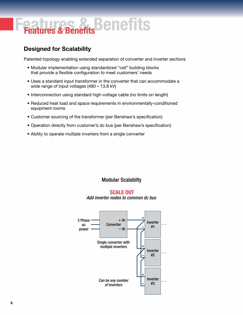
Patented topology enabling extended separation of converter and inverter sections
•Modularimplementationusingstandardized“cell”buildingblocks that provide a flexible configuration to meet customers’ needs
•Usesastandardinputtransformerintheconverterthatcanaccommodatea wide range of input voltages (480 – 13.8 kV)
•Interconnectionusingstandardhigh-voltagecable(nolimitsonlength)
•Reducedheatloadandspacerequirementsinenvironmentally-conditioned equipment rooms
•Customersourcingofthetransformer(perBenshaw’sspecification)
•Operationdirectlyfromcustomer’sdcbus(perBenshaw’sspecification)
•Abilitytooperatemultipleinvertersfromasingleconverter
Designed for Scalability
Modular Scalabilty
SCALE OUT Add inverter nodes to common dc bus
Features & BenefitsFeatures & Benefits
Can be any number of inverters
3 Phase ac
power
Inverter#2
Single converter with multiple inverters
Converter
Inverter#3
Inverter#1
+ dc
– dc
+
–
+
–
+
–

7
Features & BenefitsFeatures & Benefits
•Arcflashfootprintinherentlylower
-Utilizesdistributedenergystorage
-Nocentralizedbulkstoragecapacitors
-Opticalarcflashdetectionineachpowercelltoinstantaneously de-energizethedrive
-Offendingcellisimmediatelyreportedtothecontrolsystem
•FaultcurrentsgreatlyreducedcomparedtootherVFDs
- Converter will not feed energy into faults
•Increasedusersafetyworkenvelope
-RemotecontrolviaBluetooth® connection, or serial communication, using HMI, PC, or intelligent handheld device
•Motorizeddisconnectswitch(option)withremotecontrol
Arc Flash Resistant – Safety by Design
Topology supports cell fault isolation
Secured gateway ready to facilitate wireless /
internet connection
Remote monitoring and control
Cell arc flash detection
Q1
Q2
Q3
Q4
C2
C1
Q1
Q2
Q3
Q4
C2
C1
Q1
Q2
Q3
Q4
C2
C1
+
Safety by Design
Upper leg cell configuration

8
•Uniquemodularinverterdesignhasimprovedefficiencyover Cascaded H-Bridge and Neutral Point Clamped (NPC) inverter designs
•UsesthelatestinefficientIGBTdesignsforminimumlossesandmaximumperformance
•Inverterlosses≤0.5%overawidespeedrangeandwideloadrange
•Themodularinverterdesignallowstheinputconvertertooperatemoreefficiently than other inverter designs reducing losses
•Noefficiencyreducingoutputtransformersoroutputfiltersarerequired
•Inputpowersupplypowerfactorof≥0.95minimizeslossesinthepowersupply and input wiring
Energy Efficiency
Features & BenefitsFeatures & Benefits
•Shaftpowerofmotordrivenequipment(fans,pumps,blowers)isproportional to the cube of the rotational speed
•Bydesign,variablefrequencydrives(VFDs)improveefficiencyatalowspeed
•ConsiderableenergysavingscanbeachievedbyoutfittingmotorswithVFDs, the speed can then be adjusted to match the required load
Energy Savings
Full Load Efficiency Benshaw Others
Inverter 99.5% 99%
InputConverter 98% 97–98% and Transformer
Total Efficiency 98% 96–97%
Energy Saving Formulas
Power Consumption with Damper Control
Power Consumption with Drive Control
Pi (kW) =
QQ0
f m i
Q / Q0
0
f
m
i
3
P0Pd (kW)= 0
m0
0
f0
m0
: Ratio of air flow to fan rating: Motor rated power: Fan efficiency: Motor efficiency: Drive efficiency
: Motor rated power: Fan rated efficiency: Motor rated efficiency
P
PP
f0
Power Consumption Curve
Air Flow, Speed (%)
Pow
er C
onsu
mpt
ion
/ Sha
ft Po
wer
0 80604020 1000
80
60
40
20
100
Shaft Power with Speed Control
Power Consumption with Drive Control
Power Consumption with Damper Control
ENER
GY
$A
VIN
GS

9
Isolation loop
Robust Control Architecture
Modern control platform
•Distributedcontrolwithintelligentpowercells
•Ultra-fastCPUcoreforhigh-speedprocessingandexpansioncapability
•Industry-standardcardcage
- Front access for easy removal and replacement
- Low Voltage Differential Signaling backplane — EMI resistant
•StandardPLCI/O
-UserI/Omodulesforeveryapplicationpossibility
- Industrial process control using ladder logic
•Industrystandardfieldbusesandcommunicationprotocols
- ProfibusDP,ModbusTCP/IP,embeddedwebserver,EthernetIP,DeviceNet
•BenshawConnectTM for monitoring, parameter setting and data logging at the drive or over the internet
•Wirelessconnectivityavailableforsafeandsecurecommunication
Card Rack
PLC
PC
HMI Ethernet switch
Cell Circuit Configuration
Benshaw ConnectTM
Ethernet
IndustrialRS-485
Com
mun
icat
ion
optio
ns
Ethernet on fiber to cell control board
CPU HUB controller
Fiber optic fan out board 1
12
Fiber optic fan out board 3
12
Fiber optic fan out board 2
12
LVDS backplane
Power supply
Send
Receive
To FOB
To dc/cell
To dc/cell
Q1
Q2
Q3
Q4
C2
C1Cell control board (CCB)
Features & BenefitsFeatures & Benefits

10
Features & BenefitsFeatures & Benefits
User Interface
•Intuitive,user-friendlyTCP/IPtouchscreeneasily customizableforspecificprocesscontroluse
•Noneedtoremembermulti-usekeyassignments used on other low-end digital operators
•Custommanagedapplicationsforprocesscontrol,diagnostics,andtrending
•BenshawConnectTM Tool Suite
- Applications allow for seamless connectivity between a PC and the drive
- Easy to use configuration and diagnostics tool
-Windows-basedtoolforuseonXPandWindows7

11
Features & BenefitsFeatures & Benefits
Minimized Harmonics
Converter Input
Input Current Waveform
5th 7th 11th 13th 17th 19th 23rd 25th THD
Benshaw 0.78% 0.33% 0.085% 0.19% 1.45% 1.1% 0.14% 0.089% 2.28%
IEEE-519 4% 4% 2% 2% 1.5% 1.5% 0.6% 0.6% 5%
Typical Input Current Harmonics (at full load)
The near sinusoidal input current with minimal harmonics easily meets IEEE-519 recommended standards without the need for any extra input filters or harmonic compensation. This minimizes installation and site issues.
Output Waveform
Line-to-Line Voltage Output
•MultiplePWMoutputlevelsprovideanearsinusoidaloutput
•MultiplePWMoutputlevelsreduceoutputvoltagedv/dtoverotherMVinverter designs and are similar to low voltage variable frequency drive levels
•Minimaloutputvoltageandcurrentharmonicdistortionmaximizesmotorefficiency
•Cleanoutputmakesitpossibletouseexistingmotorsandcableswithouttheneedfor extra output filters or other additional components
•LowHVF(HarmonicVoltageFactor)levels;HVC≤0.06at≤20Hzoutputand HVC≤0.02at>20Hzoutputfrequency

12
Protective FunctionsProtective Functions
Motor and Drive Protections
Power Cell Protections
DC Bus Overvoltage Detects an overvoltage condition on the DC bus
DC Bus Undervoltage Detects an undervoltage condition on the DC bus
Output Phase Loss Detects an open phase on the drive output
Drive Thermal Overload Drive overload protects the drive hardware from overheating
Motor Overcurrent During normal operation can protect against a motor overcurrent condition
Motor Thermal Overload User adjustable electronic motor overload with speed and cooling type compensation
Motor Undercurrent During normal operation can protect against a loss of load
Ground Fault Trips drive when a ground fault condition in the motor or motor cables is detected
Drive Output Short Circuit Protection Protects drive against short on the drive’s output
Transformer Overtemperature Trips drive when a transformer overtemperature condition is detected
Control Card Fault Occurs when a problem with the control hardware is detected
Cell Overcurrent Detects a current level inside the cell above the cell specified overcurrent level
Cell Overvoltage Detects an overvoltage condition on one of the cell’s capacitors
IGBT Overtemperature Detects an overtemperature condition of a cell’s IGBT
IGBT Switching Fault Detects incorrect switching of a cell’s IGBTs
Cell Parameter Initialization Error Indicates that initialization parameters for a cell were not valid
Cell Initialization Offset Error Indicates that the initialization check for current sensing circuitry did not pass
Cell Arc Flash Detected Indicates that an arc flash condition with detected within the cell enclosure
Cell Power Supply Fault Indicates that one of the cell’s power supply voltages is out of range
Cell Communication Fault Indicates that communications with the cell have been disrupted
NOTE: Not all functions are listed.

13
Software FeaturesSoftware Features
Start and Stop Functions
Speed Search Starting Catches a spinning motor and brings it to the commanded frequency
Brake then Start Applies high slip / dc brake before starting motor
Controlled Fault Stop If enabled and selected faults occur allows drive to complete deceleration or braking before shutting down, reduces instances of water hammer, etc.
Speed Functions
Multiple Acceration and Linear, S- Curve, and U-curve Deceleration Profiles
Optimal Deceleration Allows the motor to slow down at the maximum rate without excessive regeneration and resultant bus overvoltage trips
Skip Frequencies Three user-selectable frequencies that can be used to avoid machine resonance problems by preventing continuous operation at these speeds
Dwell Frequency During acceleration and/or deceleration holds a specific frequency to allow process specific actions to occur (such as opening valves, etc.)
Maximum Frequency Limit Sets the maximum frequency that the drive will output to prevent potential motor overspeed situations
Motor Control Functions
Sensorless Vector Control Implements a sensorless vector control algorithm for optimal motor control
Volts-to-Hertz Control Provides V/Hz control for situations that require V/Hz control
Slip Compensation When in V/Hz mode provides compensation of slip to provide desired motor shaft speed
Multiple Flux Profiles Provides linear flux, squared flux, and user-defined flux profile
Automatic and Manual Torque Boost Provides low frequency torque boost in selected control modes
Motor Autotuning Function Using user-provided motor nameplate data and detected motor parameters the drive calculates the motor information needed for the sensorless vector control algorithm
Metering Functions
Extensive Metering Functions Display applied motor voltage, phase currents, motor power factor, output power, dc link voltage, IGBT temperatures
Logging Functions
Fault Log Logs faults, time and date, and a snapshot of meter data at the time of a fault condition to provide fault resolution
Event Log Logs event, time, and data of drive events (such as starts and stops)
Software Features
NOTE: Not all functions are listed.

14
60.75 inches
DimensionsDimensions
Inverter front/rear1,000 HP / 4,160 Vac
Inverter side
Input/output section
54.75 inches
Cell section
Control section
Exhaust fan assembly
50.5 inches
40.25 inches
9.25 inches
64 inches

15
Converter front/rear
63.25 inches
50.5 inches
59.25 inches
40 inches
9.25 inches
68.5 inches
Exhaust fan assembly
Transformer section
Rectifier section
Converter side
DimensionsDimensions

16
SpecificationsSpecifications
ElectricalInverter Output - Variable Torque Ratedoutputpower kW: 746 Outputvoltage V: 0–4160 Outputfrequencymin/max Hz: 0–180 Ratedoutputcurrent A: 0–140at60Hz 0–133at120Hz Requiredauxiliarysupply AC: 208/240V,50Hz/60Hz,30A
Converter Input Ratedsupplyvoltage V: 480-13.8kV Ratedsystemfrequency Hz: 45–66 Inputdistortion IEEE519 Ratedinputcurrentat4,160V A: 144 Voltagevariations Steadystate: ±10% Transientstate: +10%,-30%for30linecycles Frequencyvariations Steadystate: 95–105% Transientstate: ±5%/sec.
Environmental Conditions Ambienttemperature ºC: Min.0(nofrost),Max.50 Humidity %: 95,nodrip.water,nocondensation Air quality No corrosive gases Pollution IEC61010-1andUL840Degree2 IEC60664-3(Optional) Vibration MIL-STD-810Ffor2.5hours Seismic IBC-2006 (3G on stiff soil) Altitude meters: 1,000 4,000 derated operation
Cooling System Coolingmethod Inverter/Converter Forcedair Heatlossatfullload Inverter kW: 3.7 (max) Converter kW: 15
Construction Power connection entry bottom or top Power connection type Inverter cables Converter cables Auxiliary cables entry bottom or top Dimensions Inverter heightxwidthxdepth in: 64x61x40 Converter in: 69x64x40 Minimumclearancerequired: frontxbackxsidexabove in: 36x0x0x36 Totalweight Inverter lb: 1,452 Converter lb: 6,200 Lifting of cabinets channel slots in bottom cabinet frames
Typical for 1,000 HP

MEDIUM VOLTAGE VFD - Application Checklist
Your name _____________________________________________________ Date ___________________________Customer’s name ________________________________________________ Quote due date _______________________________________________Project name ___________________________________________________ Project location _______________________________________________Type of customer: OEM Distributor End User Project Status: Budgetary FundedEst. purchase date _______________________________________________ Est. installation / commissioning date _______________________________User’s country __________________________________________________ Competitor(s) ________________________________________________Your ref. no. ____________________________________________________ Attached documents ___________________________________________Existing Benshaw customer: Yes No Quantity of identical drives _______________________________________
Specifications
_________________________________________________________________________________________ Pump Fan Blower Compressor Extruder Other
Variable torque Proportional torque Motor Inertia ___________ kg•m2 Constant torque Constant HP
Annual operating time ___________ hours Actual motor current (If existing motor) ___________ A
TYPE: Squirrel-cage induction Synchronous Wound-rotor Other (describe)REUSE/NEW: Retrofit existing motor: mfr. and model #: _____________________________ New motor
Output: ___________ kW Voltage ___________ Vac Frequency ___________ Hz ___________ HP Poles ___________ P Speed ___________ RPMRated current ___________ A Efficiency ___________ % Power factor ___________
Min ___________ RPM Max ___________ RPM or Min ___________ Hz Max ___________ Hz
4 to 20 mA Manual speed potentiometer Multi-step digital presets
Internal accel time ___________ sec./ ___________ RPM Decel time ___________ sec./ ___________ RPM External (customer control of ramps) Define: _____________________________________________________
Not needed (100% rated output current continuous) Needed when motoring ___________ % rated output current for ___________ sec. ___________ min.
TYPE: ATL (Across-the-line) RVSS (Reduced Voltage Soft Starter) Combined None
Input power source: Grid Private Power Supply Variable Transformer GeneratorPower supply short-circuit capacity ___________ MVA Input voltage ___________ Vac ___________ HzControl circuit voltage (customer supplied) 208/220V, 50/60Hz, 3-Phase 380V, 50Hz, 3-Phase
Outdoor (Enclosure supplied by others) Indoor Other (Provide details in the “Other required specifications” section on page 2)Air-conditioning facilities: Provided Not providedAmbient temperature Min ___________ °C to Max ___________ °CHumidity ___________ % or less, non-condensing Altitude ___________ m or lessCabinet enclosure ___________ Atmosphere ___________
Type ___________ Dimentional Restrictions: _______height x _______width x _______depth None
Item
1. Name of facility or application
2. Type of application
3. Load characteristics
4. Operating conditions
5. Motor characteristics
6. Motor specifications
7. Speed control range
8. Speed reference
9. Accel / Decel ramps
10. Overload capacity
11. Drive bypass
12. Input power supply specifications
13. Ambient conditions
14. Enclosure

Item
15. Options a. Cabinet paint
b. Incoming wiring location
c. Analog outputs
d. Digital outputs
e. Digital inputs
f. Analog inputs
g. Motor temperature monitor
h. Communication option
i. Recommended spare parts j. Witness test k. Load test
Other required specifications:
Specifications
Standard specification Optional specification
Standard color (ANSI 61 Gray) Non-Standard color Define: _______________________________________
Bottom Top
Quantity (8) Quantity / description: (4) -10 to +10 Vdc 0 to 10 V ______________________________ (4) 4 to 20 mA 0 to 20 mA ______________________________ 4 to 20 mA ______________________________ Resolution: ______________________________
Quantity (4) - Relay N.O. Quantity / description: Relay ______________________________
Quantity (5) - 120 Vac Quantity / description: 24 Vdc ______________________________ 120 Vac ______________________________ 230 Vac ______________________________
Quantity (5) Quantity / description: (1) -10 to +10 Vdc 4 to 20 mA ______________________________ (4) 4 to 20 mA 0 to 10 V ______________________________ 10 to 20 V ______________________________ Resolution: ______________________________
Without Motor stator winding temperature Motor stator winding and bearing temperature TYPE: Contact (Thermostat) RTD (Pt100 ohm) 10 ohm
Without With DeviceNet Profibus-DPV1 Ethernet/IP Modbus TCP Profinet Other: ____________________ Integrator: _______________________________
Without With Without With Without With
______________________________________________________________________________________________________________________________________________________________________________________________________________________________________________________________________________________________________________________________________________________________________________________________________________________________________________________________________________________________________________________________________________________

19
Connection DiagramConnection Diagram

MKT125-009
Visit us online at benshaw.cwfc.com and benshawexpress.com, or contact:
BENSHAW, Inc.
615 Alpha DrivePittsburgh, PA 15238
Phone: 412.968.0100 Fax: 412.968.5415
BENSHAW Canada
550 Bright Street East Listowel, Ontario N4W 3W3
Phone: 519.291.5112 Fax: 519.291.2595
BENSHAW Pueblo
1 Jetway CourtPueblo, CO 81001
Phone: 719.948.1405Fax: 719.948.1445
BENSHAW China
No. 3 Quanhui RoadWuqing Development AreaTianjin City, China 301700
Phone: +86 22 8216 6100Fax: +86 22 8216 6160
Specifications are subject to change without notice.© 2012 Curtiss-Wright Flow Control Corporation.
24/7 Technical SupportBenshaw is dedicated to providing comprehensive 24-hour-a-day, 7-day-a-week phone support. Benshaw provides repair, spare parts, field engineering, retrofit, and training services, when and where you need us. You can count on our experienced team, backed by the latest diagnostics and repair tools and an extensive parts inventory to support your operations. Call 1.800.203.2416
24/7 Hotline Support from our operations in Pittsburgh and Listowel (Canada):
•Technical phone support • Overnight parts shipment • 24-hour service dispatch • Coordination of all service capabilities
RepairsRepairs are made on Benshaw equipment by trained, experienced personnel, using the latest diagnostic and test equipment.
Field Services are performed on-site by skilled technicians, engineers, or complete teams if needed, including:
• Start-up commissioning• Field repairs• Field analysis/data collection• Preventative maintenance
The Benshaw Product LineA wide range of motor controls and drives are available.
• Solid state starters fractional up to 30,000 HP at 15 kV • LV AC drives to 700 HP, MV AC drives to 3,000 HP •Electromechanical controls to 800 A
Benshaw Express is a 24/7 online inventory and order entry system for authorized Benshaw distributors:
• 24/7 shipment• Either air or truck delivery