m t c nordic x-lam technical ide
TRANSCRIPT

VERSION2020-08-13
T ECHNIC A L GU IDENOR DIC X-L A M
NS-GT6ENGLISH
Mass Timber Construction
NORDIC X-LAM TECHNICAL GUIDE
Mass Timber Construction
NORDIC X-LAM TECHNICAL GUIDE
514-871-8526 1 866 817-3418
HEAD OFFICE
Nordic Structures 100-1100 Canadiens-de-Montréal Avenue Montréal, Québec H3B 2S2
www.nordic.ca
GENERAL INFORMATION
TECHNICAL SUPPORT
ABOUT NORDIC
Nordic Structures is the leading innovator in mass timber
construction. Its resource comes from responsibly
managed lands within the regional boreal forest. Vertical
integration, from forest to structure, bolstered by Nordic’s
experienced design and development team, ensures
consistent quality and unparalleled level of service.

12345
NS-GT6 iT E C H N I C A L G U I D E N O R D I C X- L A M
VERSION 2020-08-13
NORDIC X-LAM
STRUCTURE
STRUCTURAL DETAILS
ARCHITECTURAL DETAILS
ADDITIONAL INFORMATION
TABLE OF CONTENTS
NS-GT3 NS-GT4
ii NS-GT6 T E C H N I C A L G U I D E N O R D I C X- L A M
VERSION 2020-08-13 ENGINEERED WOOD PRODUCTSStandard size products available
from our distributors
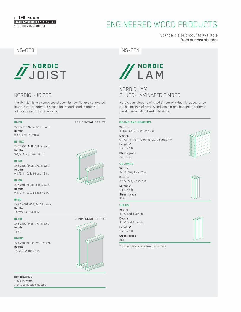
NORDIC I-JOISTSNordic I-joists are composed of sawn lumber flanges connected by a structural oriented strand board and bonded together with exterior-grade adhesives.
NI-20 RESIDENTIAL SERIES
2×3 S-P-F No. 2, 3/8 in. web Depths 9-1/2 and 11-7/8 in.
NI-40X
2×3 1950f MSR, 3/8 in. web Depths 9-1/2, 11-7/8 and 14 in.
NI-60
2×3 2100f MSR, 3/8 in. web Depths 9-1/2, 11-7/8, 14 and 16 in.
NI-80
2×4 2100f MSR, 3/8 in. web Depths 9-1/2, 11-7/8, 14 and 16 in.
NI-90
2×4 2400f MSR, 7/16 in. web Depths 11-7/8, 14 and 16 in.
NI-60 COMMERCIAL SERIES
2×3 2100f MSR, 3/8 in. web Depth 18 in.
NI-80X
2×4 2100f MSR, 7/16 in. web Depths 18, 20, 22 and 24 in.
RIM BOARDS 1-1/8 in. width I-joist compatible depths
NORDIC LAM GLUED-LAMINATED TIMBERNordic Lam glued-laminated timber of industrial appearance grade consists of small wood laminations bonded together in parallel using structural adhesives.
BEAMS AND HEADERS
Widths 1-3/4, 3-1/2, 5-1/2 and 7 in.
Depths 9-1/2, 11-7/8, 14, 16, 18, 20, 22 and 24 in.
Lengths* Up to 48 ft
Stress grade 24F-1.9E
COLUMNS
Widths 3-1/2, 5-1/2 and 7 in.
Depths 3-1/2, 5-1/2 and 7 in.
Lengths* Up to 48 ft
Stress grade ES12
STUDS
Widths 1-1/2 and 1-3/4 in.
Depths 5-1/2 and 7-1/4 in.
Lengths* Up to 48 ft
Stress grade ES11
* Larger sizes available upon request
NS-GT5 NS-GT6
NS-GT6 iiiT E C H N I C A L G U I D E N O R D I C X- L A M
VERSION 2020-08-13
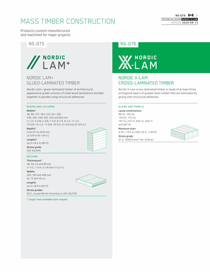
NORDIC LAM+ GLUED-LAMINATED TIMBERNordic Lam+ glued-laminated timber of architectural appearance grade consists of small wood laminations bonded together in parallel using structural adhesives.
BEAMS AND COLUMNS
Widths* 38, 86, 137, 184, 215, 241, 292, 346, 395, 448, 502, 552 and 603 mm (1-1/2, 3-3/8, 5-3/8, 7-1/4, 8-1/2, 9-1/2, 11-1/2, 13-5/8, 15-1/2, 17-5/8, 19-3/4, 21-3/4 and 23-3/4 in.)
Depths* From 67 to 2435 mm (2-5/8 to 95-7/8 in.)
Lengths* Up to 24.4 m (80 ft)
Stress grade 24F-ES/NPG
DECKING
Thicknesses* 38, 44, 54 and 89 mm (1-1/2, 1-3/4, 2-1/8 and 3-1/2 in.)
Widths 203, 305 and 406 mm (8, 12 and 16 in.)
Lengths Up to 18.9 m (62 ft)
Stress grades ES11, except 89 mm thickness in 20F-ES/CPG
* Larger sizes available upon request
NORDIC X-LAM CROSS-LAMINATED TIMBERNordic X-Lam cross-laminated timber is made of at least three orthogonal layers of graded sawn lumber that are laminated by gluing with structural adhesives.
SLABS AND PANELS
Layup combinations 89-3s, 105-3s, 143-5s, 175-5s, 197-7s, 213-7l, 244-7s, 244-7l and 267-9l
Maximum sizes 2.70 × 19.5 m (106-1/4 in. × 64 ft)
Stress grade E1 (L 1950Fb and T No. 3/Stud)
MASS TIMBER CONSTRUCTIONProducts custom-manufactured and machined for major projects

VERSION2020-08-13
1
T ECHNIC A L GU IDENOR DIC X-L A M
NS-GT6ENGLISH
NORDIC X-LAM

nordic .ca
CLT
1.2 NS-GT6 T E C H N I C A L G U I D E N O R D I C X- L A M
VERSION 2020-08-13
89-3s
105-3s
143-5s
175-5s
197-7s
213-7l
244-7s
244-7l
267-9l
3 LAYERS
5 LAYERS
7 LAYERS 9 LAYERS
NORDIC X-LAM CROSS-LAMINATED TIMBERNordic X-Lam cross-laminated timber is made of at least three orthogonal layers of graded sawn lumber that are laminated by gluing with structural adhesives.
SLABS AND PANELS
Layup combinations 89-3s, 105-3s, 143-5s, 175-5s, 197-7s, 213-7l, 244-7s, 244-7l and 267-9l
Maximum sizes 2.70 × 19.5 m (106-1/4 in. × 64 ft)
Stress grade E1 (L 1950Fb and T No. 3/Stud)
NORDIC X-LAM LAYUP COMBINATIONS
nordic .ca
NS-GT6 1.3T E C H N I C A L G U I D E N O R D I C X- L A M
VERSION 2020-08-13
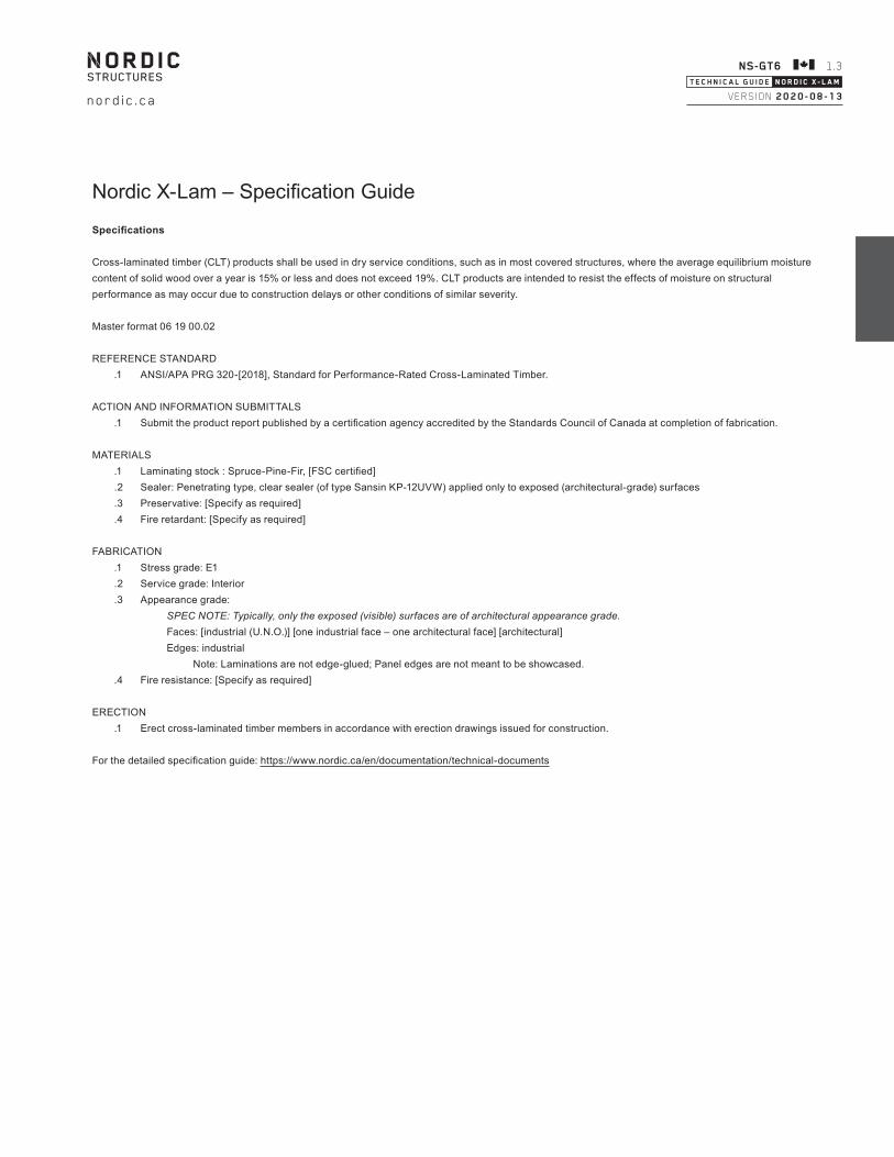
Nordic X-Lam – Specification Guide
Specifications
Cross-laminated timber (CLT) products shall be used in dry service conditions, such as in most covered structures, where the average equilibrium moisture content of solid wood over a year is 15% or less and does not exceed 19%. CLT products are intended to resist the effects of moisture on structural performance as may occur due to construction delays or other conditions of similar severity.
Master format 06 19 00.02
REFERENCE STANDARD.1 ANSI/APA PRG 320-[2018], Standard for Performance-Rated Cross-Laminated Timber.
ACTION AND INFORMATION SUBMITTALS.1 Submit the product report published by a certification agency accredited by the Standards Council of Canada at completion of fabrication.
MATERIALS.1 Laminating stock : Spruce-Pine-Fir, [FSC certified].2 Sealer: Penetrating type, clear sealer (of type Sansin KP-12UVW) applied only to exposed (architectural-grade) surfaces.3 Preservative: [Specify as required].4 Fire retardant: [Specify as required]
FABRICATION.1 Stress grade: E1.2 Service grade: Interior.3 Appearance grade:
SPEC NOTE: Typically, only the exposed (visible) surfaces are of architectural appearance grade.Faces: [industrial (U.N.O.)] [one industrial face – one architectural face] [architectural]Edges: industrial
Note: Laminations are not edge-glued; Panel edges are not meant to be showcased..4 Fire resistance: [Specify as required]
ERECTION.1 Erect cross-laminated timber members in accordance with erection drawings issued for construction.
For the detailed specification guide: https://www.nordic.ca/en/documentation/technical-documents
nordic .ca
1.4 NS-GT6 T E C H N I C A L G U I D E N O R D I C X- L A M
VERSION 2020-08-13
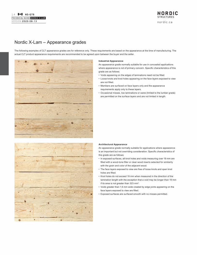
Nordic X-Lam – Appearance grades
The following examples of CLT appearance grades are for reference only. These requirements are based on the appearance at the time of manufacturing. The actual CLT product appearance requirements are recommended to be agreed upon between the buyer and the seller.
Industrial AppearanceAn appearance grade normally suitable for use in concealed applications where appearance is not of primary concern. Specific characteristics of this grade are as follows:• Voids appearing on the edges of laminations need not be filled.• Loose knots and knot holes appearing on the face layers exposed to view
are not filled.• Members are surfaced on face layers only and the appearance
requirements apply only to these layers.• Occasional misses, low laminations or wane (limited to the lumber grade)
are permitted on the surface layers and are not limited in length.
Architectural AppearanceAn appearance grade normally suitable for applications where appearance is an important but not overriding consideration. Specific characteristics of this grade are as follows:• In exposed surfaces, all knot holes and voids measuring over 19 mm are
filled with a wood-tone filler or clear wood inserts selected for similarity with the grain and color of the adjacent wood.
• The face layers exposed to view are free of loose knots and open knot holes are filled.
• Knot holes do not exceed 19 mm when measured in the direction of the lamination length with the exception that a void may be longer than 19 mm if its area is not greater than 323 mm2.
• Voids greater than 1.6 mm wide created by edge joints appearing on the face layers exposed to view are filled.
• Exposed surfaces are surfaced smooth with no misses permitted.

nordic .ca
NS-GT6 1.5T E C H N I C A L G U I D E N O R D I C X- L A M
VERSION 2020-08-13
Nordic X-Lam – Certifications
Product certificationsNordic X-Lam cross-laminated timber (CLT) products, certified by APA – The Engineered Wood Association (apawood.org), are manufactured in accordance with the applicable standards and associated specifications indicated below:• ANSI/APA PRG 320, Standard for Performance-Rated Cross-Laminated Timber• CCMC Listing 13654-L• APA Product Report PR-L306C
APA is a not-for-profit trade association and is accredited by the Standards Council of Canada (SCC) as a Product Certification Body under ISO Guide 65. APA is also an accredited testing organization recognized by SCC under ISO/IEC 17025.
The ANSI/APA PRG 320 standard is recognized in the National Building Code (NBC) and is required for using the design provisions specified in CSA O86, Engineering design in wood.
Green certificationsWood – efficient and ecologicalOverview of environmental certifications• Green Verification Report APA GR-L306• Low Formaldehyde Emissions Products APA PR-E740• Environmental Product Declaration (EPD), Nordic X-Lam• Health Product Declaration (HPD), Nordic X-Lam• Declare (ILFI), Nordic X-Lam• FSC-certified products available
See nordic.ca for details.
nordic .ca
1.6 NS-GT6 T E C H N I C A L G U I D E N O R D I C X- L A M
VERSION 2020-08-13
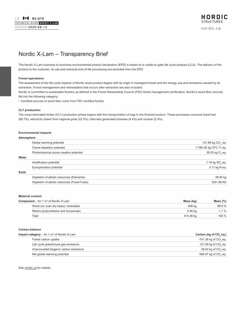
Nordic X-Lam – Transparency Brief
The Nordic X-Lam business-to-business environmental product declaration (EPD) is based on a cradle-to-gate life cycle analysis (LCA). The delivery of the product to the customer, its use and eventual end-of-life processing are excluded from the EPD.
Forest operationsThe assessment of the life cycle impacts of Nordic wood product begins with its origin in managed forests and the energy use and emissions caused by its extraction. Forest management and reforestation that occurs after extraction are also included.Nordic is committed to sustainable forestry as defined in the Forest Stewardship Council (FSC) forest management certification. Nordic’s wood fiber sources fall into the following category:• Certified sources of wood fiber come from FSC certified forests
CLT productionThe cross-laminated timber (CLT) production phase begins with the transportation of logs to the finished product. These processes consume fossil fuel (65.7%), electricity drawn from regional grids (22.5%), internally generated biomass (9.4%) and nuclear (2.4%).
Environmental impacts Atmosphere Global warming potential 121.89 kg CO2 eq.
Ozone depletion potential 1.79E-06 kg CFC-11 eq.
Photochemical ozone creation potential 35.53 kg O3 eq.
Water Acidification potential 1.19 kg SO2 eq.
Eutrophication potential 0.11 kg N eq.
Earth Depletion of abiotic resources (Elements) 38.84 kg
Depletion of abiotic resources (Fossil Fuels) 1831.88 MJ
Material content Component – for 1 m3 of Nordic X-Lam Mass (kg) Mass (%) Wood (on oven dry basis); renewable 406 kg 98.9 %
Resins (polyurethane and isocyanate) 4.46 kg 1.1 %
Total 410.46 kg 100 %
Carbon balance Impact category – for 1 m3 of Nordic X-Lam Carbon (kg of CO2 eq.) Forest carbon uptake -741.36 kg of CO2 eq.
Life cycle greenhouse gas emissions 121.89 kg of CO2 eq.
Unaccounted biogenic carbon emissions 28.50 kg of CO2 eq.
Net global warming potential -590.97 kg of CO2 eq.
See nordic.ca for details.
VERSION2020-08-13
2
T ECHNIC A L GU IDENOR DIC X-L A M
NS-GT6ENGLISH
STRUCTURE

nordic .ca
2.2 NS-GT6 T E C H N I C A L G U I D E N O R D I C X- L A M
VERSION 2020-08-13
nordic .ca
NS-GT6 2.3T E C H N I C A L G U I D E N O R D I C X- L A M
VERSION 2020-08-13
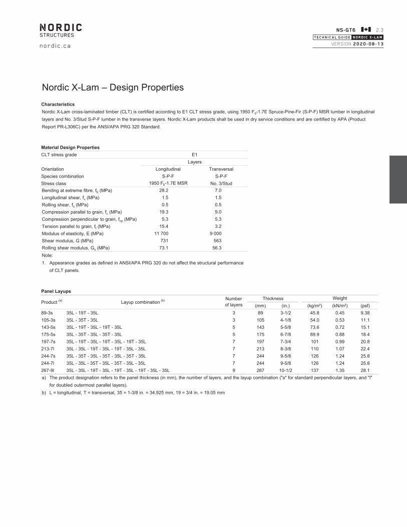
Nordic X-Lam ‒ Design PropertiesCharacteristics
Material Design PropertiesCLT stress grade E1
LayersOrientation Longitudinal TransversalSpecies combination S-P-F S-P-FStress class 1950 Fb-1.7E MSR No. 3/Stud
Panel LayupsThickness
(mm) (in.) (kg/m²) (kN/m²) (psf)89-3s 35L - 19T - 35L 3 89 3-1/2 45.8 0.45 9.38105-3s 35L - 35T - 35L 3 105 4-1/8 54.0 0.53 11.1143-5s 35L - 19T - 35L - 19T - 35L 5 143 5-5/8 73.6 0.72 15.1175-5s 35L - 35T - 35L - 35T - 35L 5 175 6-7/8 89.9 0.88 18.4197-7s 35L - 19T - 35L - 19T - 35L - 19T - 35L 7 197 7-3/4 101 0.99 20.8213-7l 35L - 35L - 19T - 35L - 19T - 35L - 35L 7 213 8-3/8 110 1.07 22.4244-7s 35L - 35T - 35L - 35T - 35L - 35T - 35L 7 244 9-5/8 126 1.24 25.8244-7l 35L - 35L - 35T - 35L - 35T - 35L - 35L 7 244 9-5/8 126 1.24 25.8267-9l 35L - 35L - 19T - 35L - 19T - 35L - 19T - 35L - 35L 9 267 10-1/2 137 1.35 28.1
Product (a) Layup combination (b) Numberof layers
Weight
28.2 7.01.5 1.50.5 0.5
19.3 9.05.3 5.3
15.4 3.211 700 9 000
731 56373.1 56.3
Note:1. Appearance grades as defined in ANSI/APA PRG 320 do not affect the structural performance
of CLT panels.
a) The product designation refers to the panel thickness (in mm), the number of layers, and the layup combination ("s" for standard perpendicular layers, and "l" for doubled outermost parallel layers).
b) L = longitudinal, T = transversal, 35 = 1-3/8 in. = 34.925 mm, 19 = 3/4 in. = 19.05 mm
Nordic X-Lam cross-laminated timber (CLT) is certified according to E1 CLT stress grade, using 1950 Fb-1.7E Spruce-Pine-Fir (S-P-F) MSR lumber in longitudinal layers and No. 3/Stud S-P-F lumber in the transverse layers. Nordic X-Lam products shall be used in dry service conditions and are certified by APA (Product Report PR-L306C) per the ANSI/APA PRG 320 Standard.
Bending at extreme fibre, fb (MPa)Longitudinal shear, fv (MPa)Rolling shear, fs (MPa)Compression parallel to grain, fc (MPa)Compression perpendicular to grain, fcp (MPa)Tension parallel to grain, ft (MPa)Modulus of elasticity, E (MPa)Shear modulus, G (MPa)Rolling shear modulus, Gs (MPa)

nordic .ca
2.4 NS-GT6 T E C H N I C A L G U I D E N O R D I C X- L A M
VERSION 2020-08-13
Floor/Roof Slabs ‒ Design Properties Floor/Roof Slabs ‒ Design PropertiesCLT stress grade E1 (L = 1950 Fb-1.7E S-P-F MSR and T = No. 3/Stud S-P-F)Layup combination 89-3s 105-3s 143-5s 175-5s 197-7s 213-7l 244-7s 244-7l 267-9l
28 38 65 87 115 157 154 199 23827 31 43 52 59 64 73 73 80
678 1 081 2 514 4 140 6 152 9 056 10 240 13 194 17 2117.5 7.3 15 15 23 25 22 22 32
0.38 1.3 5.0 11 11 5.0 26 11 115.7 10 22 31 38 22 52 31 385.2 32 261 832 1 037 261 3 199 832 1 0375.7 9.0 11 18 17 14 27 20 19
Bending about the major strength axis (y-y) Bending about the minor strength axis (x-x)
Notes:1. The tabulated design values are for dry service conditions and standard-term duration of load. 2. The compressive resistance perpendicular to grain values shall be based on S-P-F No. 3/Stud lumber (fcp = 5.3 MPa).3. The specific gravity for dowel-type fastener design, G, is 0.42.4. The density for member weight is 515 kg/m3 (5.1 kN/m3) for a moisture content of 12%.5. Design of CLT members shall be in accordance with the Update No. 1 of CSA O86-14.
a) The factored bending moment resistance values, Mr, include the resistance factor, φ, and the adjustment factor Krb as defined in the Update No. 1 ofCSA O86-14.
b) The factored shear resistance values, Vr, include the resistance factor, φ.
Bending about the major strength axis (y-y)Bending moment resistance, Mr,y (106 N-mm/m) (a)
Shear resistance, Vr,zy (103 N/m) (b)
Bending stiffness, (EI)eff,y (109 N-mm2/m)Shear rigidity, (GA)eff,zy (106 N/m)
Bending about the minor strength axis (x-x)Bending moment resistance, Mr,x (106 N-mm/m) (a)
Shear resistance, Vr,zx (103 N/m) (b)
Bending stiffness, (EI)eff,x (109 N-mm2/m)Shear rigidity, (GA)eff,zx (106 N/m)
y
xz
x
yz
nordic .ca
NS-GT6 2.5T E C H N I C A L G U I D E N O R D I C X- L A M
VERSION 2020-08-13
244-7s
244-7s
244-7s
175-5s 244-7l
143-5s
143-5s
143-5s 175-5s 197-7s 197-7s
197-7s
197-7s
175-5s 175-5s175-5s
197-7s197-7s
120 min90 min
143-5s197-7s
197-7s213-7l143-5s
143-5s143-5s
175-5s
175-5s
213-7l
143-5s
175-5s 197-7s
175-5s
175-5s 197-7s 213-7l 244-7l143-5s 197-7s 213-7l 244-7l
175-5s 197-7s143-5s 213-7l
213-7l
143-5s
143-5s 143-5s143-5s
143-5s
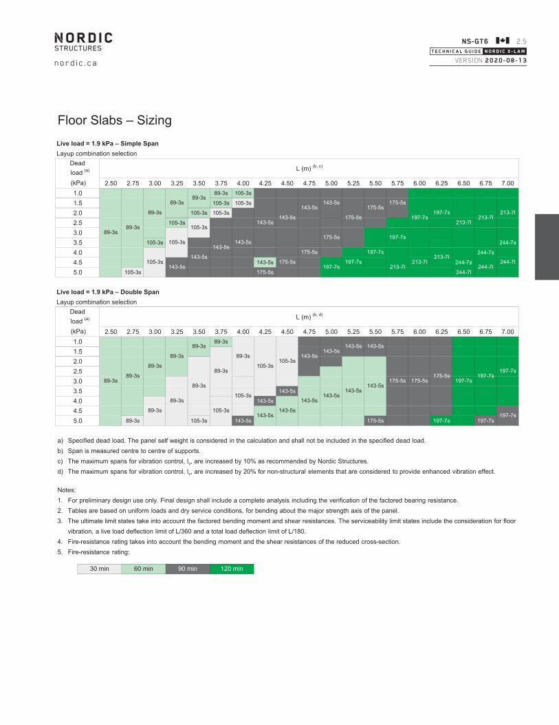
Floor Slabs ‒ SizingLive load = 1.9 kPa – Simple SpanLayup combination selection
2.50 2.75 3.00 3.25 3.50 3.75 4.00 4.25 4.50 4.75 5.00 5.25 5.50 5.75 6.00 6.25 6.50 6.75 7.001.0 89-3s 105-3s
1.5 105-3s 105-3s
2.0 105-3s 105-3s
2.5 105-3s
3.03.5 105-3s
4.04.5 143-5s
5.0 105-3s
Live load = 1.9 kPa – Double SpanLayup combination selection
2.50 2.75 3.00 3.25 3.50 3.75 4.00 4.25 4.50 4.75 5.00 5.25 5.50 5.75 6.00 6.25 6.50 6.75 7.001.0 89-3s
1.52.02.53.03.54.04.55.0 89-3s 105-3s
Dead load (a) L (m) (b, c)
(kPa)
60 min30 min
Dead load (a) L (m) (b, d)
(kPa)
89-3s89-3s
89-3s
89-3s89-3s
105-3s
105-3s
105-3s
89-3s89-3s
89-3s
89-3s
89-3s
89-3s
89-3s
89-3s143-5s
143-5s
143-5s
89-3s
89-3s105-3s
105-3s
105-3s143-5s
105-3s 143-5s143-5s
Notes:1. For preliminary design use only. Final design shall include a complete analysis including the verification of the factored bearing resistance.2. Tables are based on uniform loads and dry service conditions, for bending about the major strength axis of the panel.3. The ultimate limit states take into account the factored bending moment and shear resistances. The serviceability limit states include the consideration for floor
vibration, a live load deflection limit of L/360 and a total load deflection limit of L/180. 4. Fire-resistance rating takes into account the bending moment and the shear resistances of the reduced cross-section.5. Fire-resistance rating:
a) Specified dead load. The panel self weight is considered in the calculation and shall not be included in the specified dead load.b) Span is measured centre to centre of supports.c) The maximum spans for vibration control, lv, are increased by 10% as recommended by Nordic Structures.d) The maximum spans for vibration control, lv, are increased by 20% for non-structural elements that are considered to provide enhanced vibration effect.

nordic .ca
2.6 NS-GT6 T E C H N I C A L G U I D E N O R D I C X- L A M
VERSION 2020-08-13
244-7s
244-7s
244-7s
213-7l 244-7s 244-7l 267-9l
143-5s 143-5s
143-5s
197-7s
213-7l213-7l
213-7l244-7l
175-5s 175-5s175-5s
197-7s
197-7s197-7s
197-7s197-7s
213-7l244-7l
197-7s
213-7l
143-5s143-5s
175-5s
143-5s 175-5s
175-5s
197-7s
197-7s
175-5s
197-7s
197-7s 213-7l
197-7s
143-5s
143-5s
175-5s
143-5s 175-5s
143-5s143-5s
143-5s143-5s
175-5s175-5s
90 min 120 min
Live load = 2.4 kPa – Simple SpanLayup combination selection
2.50 2.75 3.00 3.25 3.50 3.75 4.00 4.25 4.50 4.75 5.00 5.25 5.50 5.75 6.00 6.25 6.50 6.75 7.001.0 89-3s 105-3s
1.5 105-3s
2.0 143-5s
2.5 143-5s
3.03.54.0 143-5s
4.55.0 143-5s
Live load = 2.4 kPa – Double SpanLayup combination selection
2.50 2.75 3.00 3.25 3.50 3.75 4.00 4.25 4.50 4.75 5.00 5.25 5.50 5.75 6.00 6.25 6.50 6.75 7.001.0 89-3s
1.52.02.53.03.54.04.55.0 143-5s
143-5s
143-5s
89-3s 105-3s
105-3s
105-3s
143-5s143-5s
143-5s143-5s
105-3s
105-3s
105-3s
105-3s
105-3s
Dead load (a) L (m) (b, c)
(kPa)
Dead load (a) L (m) (b, d)
89-3s
89-3s
89-3s
89-3s105-3s
(kPa)
30 min 60 min
89-3s
89-3s
89-3s
89-3s 89-3s
89-3s105-3s
89-3s 105-3s
89-3s
89-3s
a) Specified dead load. The panel self weight is considered in the calculation and shall not be included in the specified dead load.b) Span is measured centre to centre of supports.c) The maximum spans for vibration control, lv, are increased by 10% as recommended by Nordic Structures.d) The maximum spans for vibration control, lv, are increased by 20% for non-structural elements that are considered to provide enhanced vibration effect.
Notes:1. For preliminary design use only. Final design shall include a complete analysis including the verification of the factored bearing resistance and of a
concentrated live load as defined in Article 4.1.5.9. of the 2015 NBC (if applicable).2. Tables are based on uniform loads and dry service conditions, for bending about the major strength axis of the panel.3. The ultimate limit states take into account the factored bending moment and shear resistances. The serviceability limit states include the consideration for floor
vibration, a live load deflection limit of L/360 and a total load deflection limit of L/180. 4. Fire-resistance rating takes into account the bending moment and the shear resistances of the reduced cross-section.5. Fire-resistance rating:

nordic .ca
NS-GT6 2.7T E C H N I C A L G U I D E N O R D I C X- L A M
VERSION 2020-08-13
143-5s
244-7s
244-7s
244-7s
244-7s
213-7l 244-7s
143-5s
197-7s
213-7l 244-7s
244-7l
267-9l
175-5s 175-5s
175-5s175-5s
197-7s
197-7s
197-7s
213-7l
175-5s
213-7l
197-7s
197-7s 213-7l
143-5s 197-7s 213-7l
213-7l143-5s 175-5s
213-7l213-7l
213-7l244-7l
244-7l
197-7s197-7s
197-7s175-5s
197-7s
175-5s
267-9l244-7l
143-5s
143-5s
143-5s
175-5s
175-5s175-5s
90 min 120 min
143-5s
213-7l
197-7s
197-7s
197-7s
197-7s
197-7s197-7s
175-5s 197-7s
Live load = 4.8 kPa – Simple SpanLayup combination selection
2.50 2.75 3.00 3.25 3.50 3.75 4.00 4.25 4.50 4.75 5.00 5.25 5.50 5.75 6.00 6.25 6.50 6.75 7.001.01.52.02.53.03.54.04.55.0 143-5s
Live load = 4.8 kPa – Double SpanLayup combination selection
2.50 2.75 3.00 3.25 3.50 3.75 4.00 4.25 4.50 4.75 5.00 5.25 5.50 5.75 6.00 6.25 6.50 6.75 7.001.01.52.02.53.0 197-7s
3.54.04.5 197-7s
5.0 197-7s
105-3s 143-5s 143-5s
143-5s
197-7s
89-3s 105-3s 143-5s
89-3s143-5s
105-3s143-5s
Dead load (a) L (m) (b, c)
(kPa)
Dead load (a) L (m) (b, d)
89-3s
89-3s 89-3s
105-3s143-5s
30 min 60 min
89-3s
89-3s
89-3s105-3s
89-3s
89-3s
143-5s
143-5s105-3s
89-3s
(kPa)
143-5s
a) Specified dead load. The panel self weight is considered in the calculation and shall not be included in the specified dead load.b) Span is measured centre to centre of supports.c) The maximum spans for vibration control, lv, are increased by 10% as recommended by Nordic Structures.d) The maximum spans for vibration control, lv, are increased by 20% for non-structural elements that are considered to provide enhanced vibration effect.
Notes:1. For preliminary design use only. Final design shall include a complete analysis including the verification of the factored bearing resistance and of a
concentrated live load as defined in Article 4.1.5.9. of the 2015 NBC (if applicable).2. Tables are based on uniform loads and dry service conditions, for bending about the major strength axis of the panel.3. The ultimate limit states take into account the factored bending moment and shear resistances. The serviceability limit states include the consideration for floor
vibration, a live load deflection limit of L/360 and a total load deflection limit of L/180. 4. Fire-resistance rating takes into account the bending moment and the shear resistances of the reduced cross-section.5. Fire-resistance rating:
nordic .ca
2.8 NS-GT6 T E C H N I C A L G U I D E N O R D I C X- L A M
VERSION 2020-08-13
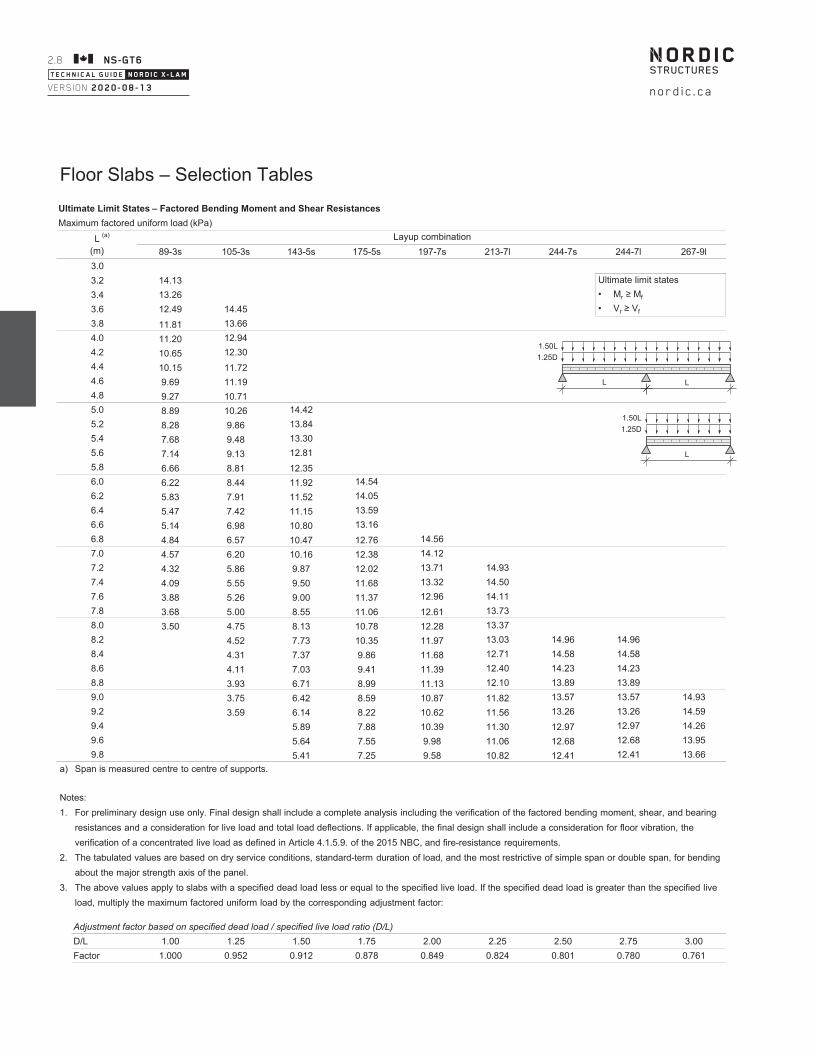
Floor Slabs – Selection TablesUltimate Limit States ‒ Factored Bending Moment and Shear ResistancesMaximum factored uniform load (kPa)
89-3s 105-3s 143-5s 175-5s 197-7s 213-7l 244-7s 244-7l 267-9l3.03.2 14.133.4 13.263.6 12.49 14.453.8 11.81 13.664.0 11.20 12.944.2 10.65 12.304.4 10.15 11.724.6 9.69 11.194.8 9.27 10.715.0 8.89 10.26 14.425.2 8.28 9.86 13.845.4 7.68 9.48 13.305.6 7.14 9.13 12.815.8 6.66 8.81 12.356.0 6.22 8.44 11.92 14.546.2 5.83 7.91 11.52 14.056.4 5.47 7.42 11.15 13.596.6 5.14 6.98 10.80 13.166.8 4.84 6.57 10.47 12.76 14.567.0 4.57 6.20 10.16 12.38 14.127.2 4.32 5.86 9.87 12.02 13.71 14.937.4 4.09 5.55 9.50 11.68 13.32 14.507.6 3.88 5.26 9.00 11.37 12.96 14.117.8 3.68 5.00 8.55 11.06 12.61 13.738.0 3.50 4.75 8.13 10.78 12.28 13.378.2 4.52 7.73 10.35 11.97 13.03 14.96 14.968.4 4.31 7.37 9.86 11.68 12.71 14.58 14.588.6 4.11 7.03 9.41 11.39 12.40 14.23 14.238.8 3.93 6.71 8.99 11.13 12.10 13.89 13.899.0 3.75 6.42 8.59 10.87 11.82 13.57 13.57 14.939.2 3.59 6.14 8.22 10.62 11.56 13.26 13.26 14.599.4 5.89 7.88 10.39 11.30 12.97 12.97 14.269.6 5.64 7.55 9.98 11.06 12.68 12.68 13.959.8 5.41 7.25 9.58 10.82 12.41 12.41 13.66
Adjustment factor based on specified dead load / specified live load ratio (D/L)D/L 1.00 1.25 1.50 1.75 2.00 2.25 2.50 2.75 3.00Factor 1.000 0.952 0.912 0.878 0.849 0.824 0.801 0.780 0.761
L (a)
(m)Layup combination
Notes:1. For preliminary design use only. Final design shall include a complete analysis including the verification of the factored bending moment, shear, and bearing
resistances and a consideration for live load and total load deflections. If applicable, the final design shall include a consideration for floor vibration, the verification of a concentrated live load as defined in Article 4.1.5.9. of the 2015 NBC, and fire-resistance requirements.
2. The tabulated values are based on dry service conditions, standard-term duration of load, and the most restrictive of simple span or double span, for bending about the major strength axis of the panel.
3. The above values apply to slabs with a specified dead load less or equal to the specified live load. If the specified dead load is greater than the specified live load, multiply the maximum factored uniform load by the corresponding adjustment factor:
a) Span is measured centre to centre of supports.
Ultimate limit states• Mr ≥ Mf
• Vr ≥ Vf
1.25D1.50L
L
1.25D1.50L
L L

nordic .ca
NS-GT6 2.9T E C H N I C A L G U I D E N O R D I C X- L A M
VERSION 2020-08-13
Serviceability Limit States ‒ L/180, Simple SpanMaximum specified uniform total load (kPa)
89-3s 105-3s 143-5s 175-5s 197-7s 213-7l 244-7s 244-7l 267-9l3.0 6.40 9.573.2 5.34 8.043.4 4.50 6.813.6 3.82 5.823.8 5.01 11.494.0 4.34 9.974.2 3.78 8.694.4 7.63 11.874.6 6.73 10.514.8 5.96 9.355.0 5.31 8.355.2 4.74 7.49 11.175.4 4.25 6.74 10.055.6 3.83 6.08 9.075.8 5.51 8.21 11.746.0 5.00 7.46 10.68 11.736.2 4.56 6.79 9.74 10.726.4 4.16 6.20 8.91 9.826.6 3.81 5.68 8.17 9.02 11.266.8 3.50 5.21 7.51 8.30 10.387.0 4.79 6.92 7.65 9.587.2 4.42 6.38 7.07 8.87 11.717.4 4.08 5.90 6.54 8.22 10.857.6 3.78 5.47 6.07 7.63 10.077.8 3.50 5.07 5.64 7.10 9.368.0 4.72 5.24 6.61 8.718.2 4.39 4.89 6.17 8.128.4 4.10 4.56 5.76 7.598.6 3.83 4.26 5.39 7.108.8 3.58 3.99 5.05 6.659.0 3.74 4.74 6.239.2 3.51 4.45 5.859.4 4.19 5.509.6 3.94 5.189.8 3.71 4.88
Adjustment factor based on specified dead load / specified live load ratio (D/L)D/L 1.00 1.25 1.50 1.75 2.00 2.25 2.50 2.75 3.00Factor 1.000 0.964 0.938 0.917 0.900 0.886 0.875 0.865 0.857
L (a)
(m)Layup combination
Notes:1. For preliminary design use only. Final design shall include a complete analysis including the verification of the factored bending moment, shear, and bearing
resistances and a consideration for live load and total load deflections. If applicable, the final design shall include a consideration for floor vibration, the verification of a concentrated live load as defined in Article 4.1.5.9. of the 2015 NBC, and fire-resistance requirements.
2. The tabulated values are based on dry service conditions, for bending about the major strength axis of the panel. 3. The above values apply to slabs with a specified dead load less or equal to the specified live load. If the specified dead load is greater than the specified live
load, multiply the maximum specified uniform total load by the corresponding adjustment factor:
a) Span is measured centre to centre of supports.
Serviceability limit states• ΔST + ΔLT Kcreep ≤ L/180
1.0D1.0L
L
nordic .ca
2.10 NS-GT6 T E C H N I C A L G U I D E N O R D I C X- L A M
VERSION 2020-08-13
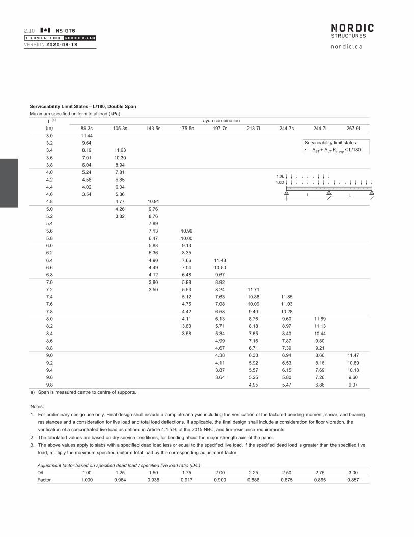
Serviceability Limit States ‒ L/180, Double SpanMaximum specified uniform total load (kPa)
89-3s 105-3s 143-5s 175-5s 197-7s 213-7l 244-7s 244-7l 267-9l3.0 11.443.2 9.643.4 8.19 11.933.6 7.01 10.303.8 6.04 8.944.0 5.24 7.814.2 4.58 6.854.4 4.02 6.044.6 3.54 5.364.8 4.77 10.915.0 4.26 9.765.2 3.82 8.765.4 7.895.6 7.13 10.995.8 6.47 10.006.0 5.88 9.136.2 5.36 8.356.4 4.90 7.66 11.436.6 4.49 7.04 10.506.8 4.12 6.48 9.677.0 3.80 5.98 8.927.2 3.50 5.53 8.24 11.717.4 5.12 7.63 10.86 11.857.6 4.75 7.08 10.09 11.037.8 4.42 6.58 9.40 10.288.0 4.11 6.13 8.76 9.60 11.898.2 3.83 5.71 8.18 8.97 11.138.4 3.58 5.34 7.65 8.40 10.448.6 4.99 7.16 7.87 9.808.8 4.67 6.71 7.39 9.219.0 4.38 6.30 6.94 8.66 11.479.2 4.11 5.92 6.53 8.16 10.809.4 3.87 5.57 6.15 7.69 10.189.6 3.64 5.25 5.80 7.26 9.609.8 4.95 5.47 6.86 9.07
Adjustment factor based on specified dead load / specified live load ratio (D/L)D/L 1.00 1.25 1.50 1.75 2.00 2.25 2.50 2.75 3.00Factor 1.000 0.964 0.938 0.917 0.900 0.886 0.875 0.865 0.857
L (a)
(m)Layup combination
Notes:1. For preliminary design use only. Final design shall include a complete analysis including the verification of the factored bending moment, shear, and bearing
resistances and a consideration for live load and total load deflections. If applicable, the final design shall include a consideration for floor vibration, the verification of a concentrated live load as defined in Article 4.1.5.9. of the 2015 NBC, and fire-resistance requirements.
2. The tabulated values are based on dry service conditions, for bending about the major strength axis of the panel. 3. The above values apply to slabs with a specified dead load less or equal to the specified live load. If the specified dead load is greater than the specified live
load, multiply the maximum specified uniform total load by the corresponding adjustment factor:
a) Span is measured centre to centre of supports.
Serviceability limit states• ΔST + ΔLT Kcreep ≤ L/180
1.0D1.0L
L L

nordic .ca
NS-GT6 2.11T E C H N I C A L G U I D E N O R D I C X- L A M
VERSION 2020-08-13
Serviceability Limit States ‒ L/360, Simple SpanMaximum specified uniform live load (kPa)
89-3s 105-3s 143-5s 175-5s 197-7s 213-7l 244-7s 244-7l 267-9l3.0 4.80 7.183.2 4.01 6.033.4 3.38 5.113.6 2.87 4.373.8 2.46 3.764.0 2.12 3.26 7.484.2 2.84 6.524.4 2.49 5.734.6 2.19 5.05 7.894.8 1.94 4.47 7.025.0 3.98 6.275.2 3.56 5.62 8.385.4 3.19 5.06 7.545.6 2.88 4.57 6.805.8 2.60 4.14 6.166.0 2.36 3.76 5.60 8.026.2 2.14 3.42 5.10 7.31 8.046.4 1.95 3.13 4.66 6.69 7.376.6 2.86 4.26 6.13 6.77 8.456.8 2.63 3.91 5.64 6.23 7.797.0 2.42 3.60 5.19 5.74 7.197.2 2.23 3.32 4.79 5.30 6.657.4 2.06 3.07 4.43 4.91 6.17 8.147.6 1.91 2.84 4.10 4.55 5.73 7.557.8 2.63 3.81 4.23 5.33 7.028.0 2.45 3.54 3.94 4.96 6.548.2 2.28 3.30 3.67 4.63 6.108.4 2.12 3.08 3.43 4.33 5.698.6 1.98 2.88 3.20 4.05 5.338.8 2.69 3.00 3.79 4.999.0 2.52 2.81 3.56 4.689.2 2.36 2.64 3.34 4.399.4 2.22 2.48 3.14 4.139.6 2.09 2.33 2.96 3.899.8 1.97 2.20 2.79 3.66
L (a)
(m)Layup combination
Notes:1. For preliminary design use only. Final design shall include a complete analysis including the verification of the factored bending moment, shear, and bearing
resistances and a consideration for live load and total load deflections. If applicable, the final design shall include a consideration for floor vibration, the verification of a concentrated live load as defined in Article 4.1.5.9. of the 2015 NBC, and fire-resistance requirements.
2. The tabulated values are based on dry service conditions, for bending about the major strength axis of the panel.
a) Span is measured centre to centre of supports.
Serviceability limit states• ΔL ≤ L/360
1.0L
L
nordic .ca
2.12 NS-GT6 T E C H N I C A L G U I D E N O R D I C X- L A M
VERSION 2020-08-13
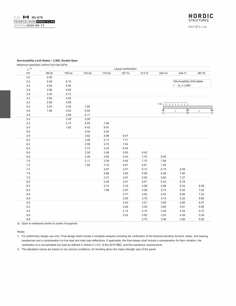
Serviceability Limit States ‒ L/360, Double SpanMaximum specified uniform live load (kPa)
89-3s 105-3s 143-5s 175-5s 197-7s 213-7l 244-7s 244-7l 267-9l3.0 6.553.2 5.49 8.103.4 4.64 6.903.6 3.96 5.933.8 3.40 5.124.0 2.94 4.454.2 2.56 3.894.4 2.24 3.42 7.854.6 1.98 3.03 6.944.8 2.69 6.175.0 2.39 5.505.2 2.14 4.93 7.665.4 1.92 4.43 6.915.6 4.00 6.265.8 3.62 5.68 8.476.0 3.28 5.17 7.716.2 2.99 4.72 7.046.4 2.73 4.32 6.446.6 2.50 3.96 5.90 8.426.8 2.29 3.64 5.43 7.75 8.497.0 2.11 3.36 5.00 7.15 7.847.2 1.94 3.10 4.61 6.61 7.267.4 2.87 4.27 6.12 6.74 8.387.6 2.66 3.95 5.68 6.26 7.807.8 2.47 3.67 5.28 5.82 7.278.0 2.29 3.41 4.91 5.43 6.788.2 2.14 3.18 4.58 5.06 6.34 8.388.4 1.99 2.97 4.28 4.73 5.93 7.848.6 2.77 4.00 4.43 5.56 7.348.8 2.59 3.75 4.15 5.22 6.899.0 2.43 3.51 3.90 4.90 6.479.2 2.28 3.30 3.66 4.61 6.089.4 2.14 3.10 3.45 4.34 5.729.6 2.02 2.92 3.25 4.09 5.399.8 2.75 3.06 3.86 5.09
L (a)
(m)Layup combination
a) Span is measured centre to centre of supports.
Serviceability limit states• ΔL ≤ L/360
Notes:1. For preliminary design use only. Final design shall include a complete analysis including the verification of the factored bending moment, shear, and bearing
resistances and a consideration for live load and total load deflections. If applicable, the final design shall include a consideration for floor vibration, the verification of a concentrated live load as defined in Article 4.1.5.9. of the 2015 NBC, and fire-resistance requirements.
2. The tabulated values are based on dry service conditions, for bending about the major strength axis of the panel.
Serviceability Limit States ‒ Vibration, Simple SpanMaximum span, lv (m)
89-3s 105-3s 143-5s 175-5s 197-7s 213-7l 244-7s 244-7l 267-9lSimple 3.75 4.21 5.19 5.85 6.47 7.17 7.31 7.86 8.41
Serviceability Limit States ‒ Vibration, Double SpanMaximum span, lv (m)
89-3s 105-3s 143-5s 175-5s 197-7s 213-7l 244-7s 244-7l 267-9lDouble 4.10 4.60 5.66 6.38 7.06 7.82 7.97 8.00 8.41
SpanLayup combination
SpanLayup combination
Notes:1. The maximum spans for vibration control, lv, are increased by 10% as recommended by Nordic Structures.2. The tabulated values apply to simply supported floor slabs.
Notes:1. The maximum spans for vibration control, lv, are increased by 20% for non-structural elements that are considered to provide enhanced vibration effect.2. If applicable, the concrete topping area density shall not be greater than twice the bare CLT floor area density.3. The tabulated values apply to simply supported floor slabs.
1.0L
L L
nordic .ca
NS-GT6 2.13T E C H N I C A L G U I D E N O R D I C X- L A M
VERSION 2020-08-13
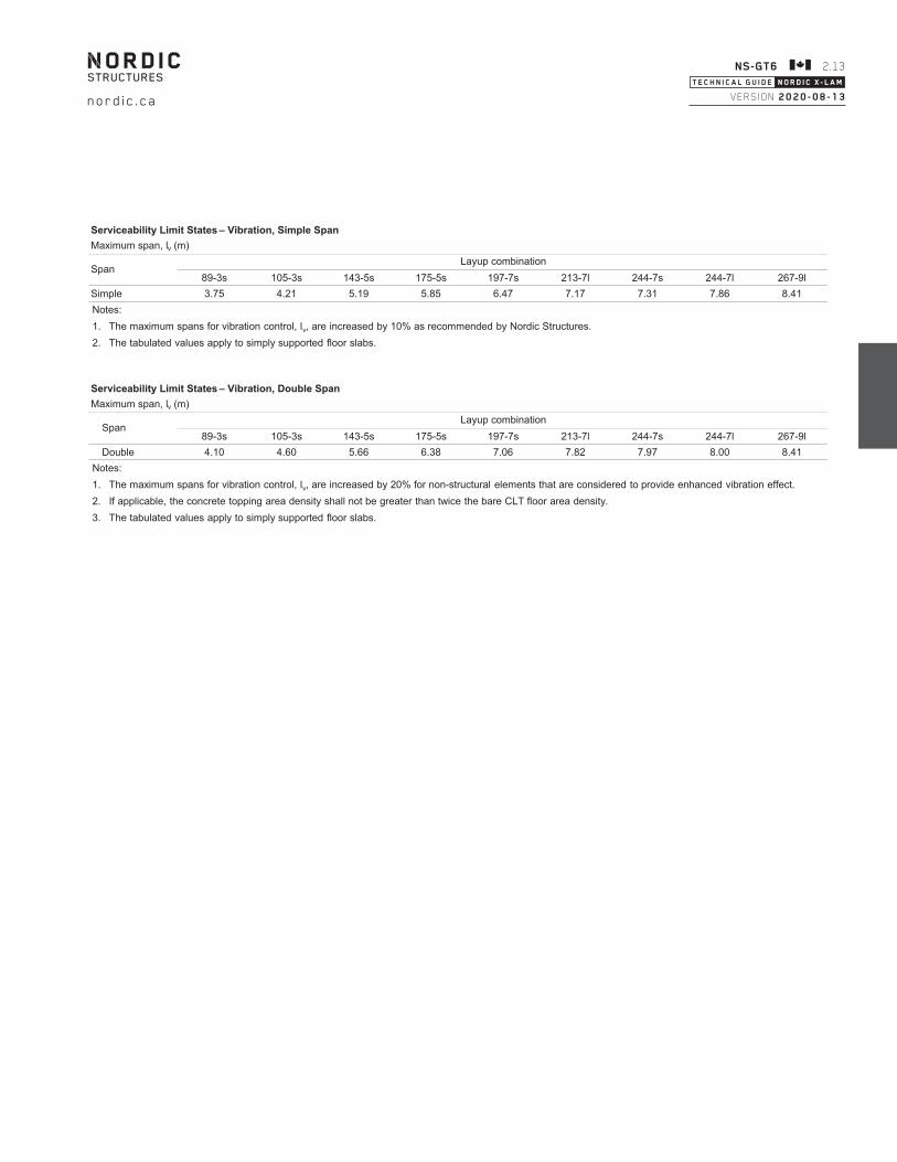
Serviceability Limit States ‒ Vibration, Simple SpanMaximum span, lv (m)
89-3s 105-3s 143-5s 175-5s 197-7s 213-7l 244-7s 244-7l 267-9lSimple 3.75 4.21 5.19 5.85 6.47 7.17 7.31 7.86 8.41
Serviceability Limit States ‒ Vibration, Double SpanMaximum span, lv (m)
89-3s 105-3s 143-5s 175-5s 197-7s 213-7l 244-7s 244-7l 267-9lDouble 4.10 4.60 5.66 6.38 7.06 7.82 7.97 8.00 8.41
SpanLayup combination
SpanLayup combination
Notes:1. The maximum spans for vibration control, lv, are increased by 10% as recommended by Nordic Structures.2. The tabulated values apply to simply supported floor slabs.
Notes:1. The maximum spans for vibration control, lv, are increased by 20% for non-structural elements that are considered to provide enhanced vibration effect.2. If applicable, the concrete topping area density shall not be greater than twice the bare CLT floor area density.3. The tabulated values apply to simply supported floor slabs.

nordic .ca
2.14 NS-GT6 T E C H N I C A L G U I D E N O R D I C X- L A M
VERSION 2020-08-13
143-5s 143-5s 175-5s
244-7s
244-7l
143-5s 143-5s
143-5s
143-5s
143-5s
143-5s
143-5s
175-5s 197-7s
213-7l
175-5s
175-5s
175-5s175-5s
175-5s 197-7s
244-7l213-7l
213-7l
197-7s
175-5s
197-7s175-5s 197-7s
175-5s
143-5s 175-5s
143-5s 175-5s 197-7s
143-5s
197-7s197-7s
213-7l
213-7l
143-5s143-5s
175-5s175-5s
143-5s
175-5s 197-7s
143-5s143-5s
143-5s 175-5s 175-5s
197-7s
143-5s
90 min 120 min
Roof Slabs ‒ SizingSnow load = 1.5 kPa – Simple SpanLayup combination selection
2.50 2.75 3.00 3.25 3.50 3.75 4.00 4.25 4.50 4.75 5.00 5.25 5.50 5.75 6.00 6.25 6.50 6.75 7.000.5 89-3s 89-3s 105-3s 105-3s 105-3s
1.0 105-3s 105-3s 105-3s
1.5 105-3s 105-3s
2.02.53.0 105-3s
3.54.0 105-3s
4.5 105-3s
Snow load = 1.5 kPa – Double SpanLayup combination selection
2.50 2.75 3.00 3.25 3.50 3.75 4.00 4.25 4.50 4.75 5.00 5.25 5.50 5.75 6.00 6.25 6.50 6.75 7.000.5 89-3s 89-3s 89-3s 89-3s 105-3s 105-3s
1.01.52.02.53.03.54.04.5 105-3s
143-5s
143-5s143-5s
143-5s
143-5s
143-5s105-3s
143-5s
89-3s
105-3s
143-5s105-3s 143-5s
105-3s 143-5s143-5s
89-3s89-3s
105-3s89-3s
89-3s 105-3s
105-3s
105-3s
105-3s
105-3s
Dead load (a) L (m) (b)
(kPa)
105-3s 105-3s
Dead load (a) L (m) (b)
89-3s 89-3s
89-3s
89-3s
89-3s89-3s
105-3s
30 min 60 min
(kPa)
89-3s
89-3s89-3s
89-3s89-3s 89-3s
89-3s89-3s
89-3s89-3s
89-3s
a) Specified dead load. The panel self weight is considered in the calculation and shall not be included in the specified dead load.b) Span is measured centre to centre of supports.
Notes:1. For preliminary design use only. Final design shall include a complete analysis including the verification of the factored bearing resistance. If applicable, the
final design shall include a consideration for vibration control and the verification of a concentrated live load as defined in Article 4.1.5.9. of the 2015 NBC.2. Tables are based on uniform loads and dry service conditions, for bending about the major strength axis of the panel. Tables also consider a normal
importance category for buildings as defined in Table 4.1.2.1. of the 2015 NBC.3. The ultimate limit states take into account the factored bending moment and shear resistances. The serviceability limit states include a snow load deflection
limit of L/240 and a total load deflection limit of L/180.4. Fire-resistance rating takes into account the bending moment and shear resistances of the reduced cross-section.5. Fire-resistance rating:
nordic .ca
NS-GT6 2.15T E C H N I C A L G U I D E N O R D I C X- L A M
VERSION 2020-08-13
143-5s 143-5s 175-5s 175-5s
244-7s
143-5s 175-5s 197-7s 213-7l 244-7s
197-7s
197-7s
197-7s 197-7s
175-5s
197-7s
175-5s
175-5s
175-5s175-5s
175-5s
143-5s 197-7s 213-7l 244-7l175-5s 244-7l
197-7s
143-5s
175-5s 197-7s
175-5s 197-7s213-7l
175-5s 197-7s 213-7l
175-5s 197-7s 213-7l
197-7s
213-7l
90 min 120 min
143-5s143-5s
143-5s143-5s
143-5s 175-5s 197-7s
143-5s175-5s
175-5s
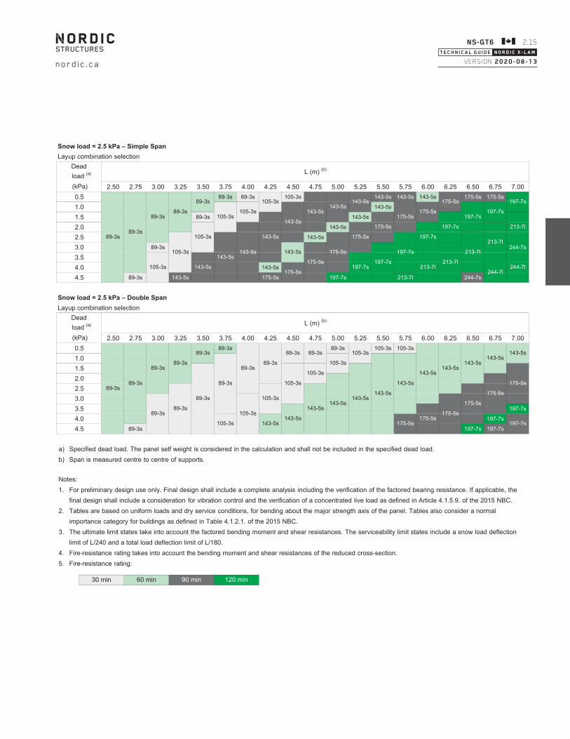
Snow load = 2.5 kPa – Simple SpanLayup combination selection
2.50 2.75 3.00 3.25 3.50 3.75 4.00 4.25 4.50 4.75 5.00 5.25 5.50 5.75 6.00 6.25 6.50 6.75 7.000.5 89-3s 89-3s 105-3s 143-5s
1.0 143-5s
1.5 89-3s 143-5s
2.0 143-5s
2.5 143-5s
3.0 89-3s
3.54.0 143-5s
4.5 89-3s
Snow load = 2.5 kPa – Double SpanLayup combination selection
2.50 2.75 3.00 3.25 3.50 3.75 4.00 4.25 4.50 4.75 5.00 5.25 5.50 5.75 6.00 6.25 6.50 6.75 7.000.5 89-3s 89-3s 105-3s 105-3s
1.01.52.02.53.03.54.04.5 89-3s
143-5s143-5s
105-3s143-5s
105-3s 143-5s
89-3s89-3s
89-3s
89-3s 105-3s
105-3s
143-5s105-3s
143-5s
143-5s89-3s 105-3s
105-3s
143-5s143-5s
143-5s
143-5s143-5s
89-3s89-3s
89-3s89-3s
89-3s
89-3s89-3s
89-3s
143-5s
30 min 60 min
89-3s89-3s
89-3s89-3s
89-3s
105-3s105-3s
105-3s
105-3s
105-3s
Dead load (a) L (m) (b)
(kPa)
(kPa)
Dead load (a) L (m) (b)
105-3s
a) Specified dead load. The panel self weight is considered in the calculation and shall not be included in the specified dead load.b) Span is measured centre to centre of supports.
Notes:1. For preliminary design use only. Final design shall include a complete analysis including the verification of the factored bearing resistance. If applicable, the
final design shall include a consideration for vibration control and the verification of a concentrated live load as defined in Article 4.1.5.9. of the 2015 NBC.2. Tables are based on uniform loads and dry service conditions, for bending about the major strength axis of the panel. Tables also consider a normal
importance category for buildings as defined in Table 4.1.2.1. of the 2015 NBC.3. The ultimate limit states take into account the factored bending moment and shear resistances. The serviceability limit states include a snow load deflection
limit of L/240 and a total load deflection limit of L/180.4. Fire-resistance rating takes into account the bending moment and shear resistances of the reduced cross-section.5. Fire-resistance rating:
nordic .ca
2.16 NS-GT6 T E C H N I C A L G U I D E N O R D I C X- L A M
VERSION 2020-08-13
143-5s 175-5s 175-5s
244-7s
244-7s
175-5s 244-7l 267-9l
197-7s
197-7s
197-7s 197-7s
244-7l
175-5s
175-5s
175-5s197-7s
175-5s 197-7s175-5s
175-5s
175-5s
175-5s 197-7s 213-7l143-5s 197-7s 213-7l
197-7s143-5s
175-5s
175-5s143-5s
143-5s
197-7s
143-5s175-5s 197-7s
197-7s
213-7l213-7l
213-7l
213-7l
244-7l
175-5s 197-7s
197-7s
197-7s143-5s
143-5s175-5s
175-5s
90 min 120 min
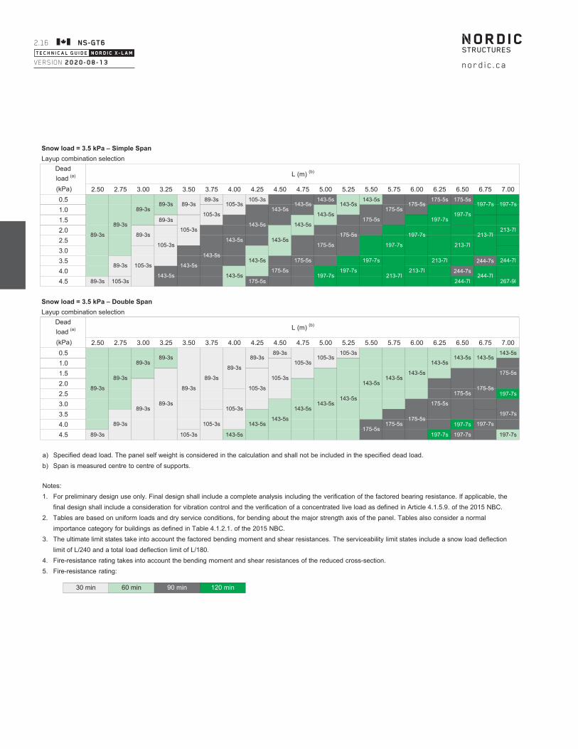
Snow load = 3.5 kPa – Simple SpanLayup combination selection
2.50 2.75 3.00 3.25 3.50 3.75 4.00 4.25 4.50 4.75 5.00 5.25 5.50 5.75 6.00 6.25 6.50 6.75 7.000.5 89-3s 105-3s 143-5s
1.01.5 89-3s
2.02.53.03.54.04.5 89-3s 105-3s
Snow load = 3.5 kPa – Double SpanLayup combination selection
2.50 2.75 3.00 3.25 3.50 3.75 4.00 4.25 4.50 4.75 5.00 5.25 5.50 5.75 6.00 6.25 6.50 6.75 7.000.5 89-3s 105-3s 143-5s
1.01.52.02.53.03.54.04.5 89-3s 105-3s 143-5s 197-7s
143-5s143-5s
143-5s143-5s
105-3s
143-5s105-3s
143-5s143-5s
143-5s
143-5s143-5s 143-5s
105-3s
89-3s105-3s
105-3s
89-3s
143-5s
89-3s
105-3s143-5s
105-3s143-5s
105-3s143-5s
105-3s 143-5s
Dead load (a) L (m) (b)
(kPa)
Dead load (a) L (m) (b)
89-3s
89-3s
89-3s89-3s 89-3s 105-3s 143-5s
30 min 60 min
(kPa)
89-3s
89-3s
89-3s89-3s
89-3s
89-3s
89-3s
89-3s
89-3s
89-3s
105-3s
a) Specified dead load. The panel self weight is considered in the calculation and shall not be included in the specified dead load.b) Span is measured centre to centre of supports.
Notes:1. For preliminary design use only. Final design shall include a complete analysis including the verification of the factored bearing resistance. If applicable, the
final design shall include a consideration for vibration control and the verification of a concentrated live load as defined in Article 4.1.5.9. of the 2015 NBC.2. Tables are based on uniform loads and dry service conditions, for bending about the major strength axis of the panel. Tables also consider a normal
importance category for buildings as defined in Table 4.1.2.1. of the 2015 NBC.3. The ultimate limit states take into account the factored bending moment and shear resistances. The serviceability limit states include a snow load deflection
limit of L/240 and a total load deflection limit of L/180.4. Fire-resistance rating takes into account the bending moment and shear resistances of the reduced cross-section.5. Fire-resistance rating:
nordic .ca
NS-GT6 2.17T E C H N I C A L G U I D E N O R D I C X- L A M
VERSION 2020-08-13
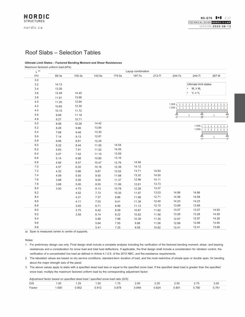
Roof Slabs – Selection TablesUltimate Limit States ‒ Factored Bending Moment and Shear ResistancesMaximum factored uniform load (kPa)
89-3s 105-3s 143-5s 175-5s 197-7s 213-7l 244-7s 244-7l 267-9l3.03.2 14.133.4 13.263.6 12.49 14.453.8 11.81 13.664.0 11.20 12.944.2 10.65 12.304.4 10.15 11.724.6 9.69 11.194.8 9.27 10.715.0 8.89 10.26 14.425.2 8.28 9.86 13.845.4 7.68 9.48 13.305.6 7.14 9.13 12.815.8 6.66 8.81 12.356.0 6.22 8.44 11.92 14.546.2 5.83 7.91 11.52 14.056.4 5.47 7.42 11.15 13.596.6 5.14 6.98 10.80 13.166.8 4.84 6.57 10.47 12.76 14.567.0 4.57 6.20 10.16 12.38 14.127.2 4.32 5.86 9.87 12.02 13.71 14.937.4 4.09 5.55 9.50 11.68 13.32 14.507.6 3.88 5.26 9.00 11.37 12.96 14.117.8 3.68 5.00 8.55 11.06 12.61 13.738.0 3.50 4.75 8.13 10.78 12.28 13.378.2 4.52 7.73 10.35 11.97 13.03 14.96 14.968.4 4.31 7.37 9.86 11.68 12.71 14.58 14.588.6 4.11 7.03 9.41 11.39 12.40 14.23 14.238.8 3.93 6.71 8.99 11.13 12.10 13.89 13.899.0 3.75 6.42 8.59 10.87 11.82 13.57 13.57 14.939.2 3.59 6.14 8.22 10.62 11.56 13.26 13.26 14.599.4 5.89 7.88 10.39 11.30 12.97 12.97 14.269.6 5.64 7.55 9.98 11.06 12.68 12.68 13.959.8 5.41 7.25 9.58 10.82 12.41 12.41 13.66
Adjustment factor based on specified dead load / specified snow load ratio (D/S)D/S 1.00 1.25 1.50 1.75 2.00 2.25 2.50 2.75 3.00Factor 1.000 0.952 0.912 0.878 0.849 0.824 0.801 0.780 0.761
L (a)
(m)Layup combination
Notes:1. For preliminary design use only. Final design shall include a complete analysis including the verification of the factored bending moment, shear, and bearing
resistances and a consideration for snow load and total load deflections. If applicable, the final design shall include a consideration for vibration control, the verification of a concentrated live load as defined in Article 4.1.5.9. of the 2015 NBC, and fire-resistance requirements.
2. The tabulated values are based on dry service conditions, standard-term duration of load, and the most restrictive of simple span or double span, for bending about the major strength axis of the panel.
3. The above values apply to slabs with a specified dead load less or equal to the specified snow load. If the specified dead load is greater than the specified snow load, multiply the maximum factored uniform load by the corresponding adjustment factor:
a) Span is measured centre to centre of supports.
Ultimate limit states• Mr ≥ Mf
• Vr ≥ Vf
1.25D1.50S
L L
1.25D1.50S
L
nordic .ca
2.18 NS-GT6 T E C H N I C A L G U I D E N O R D I C X- L A M
VERSION 2020-08-13
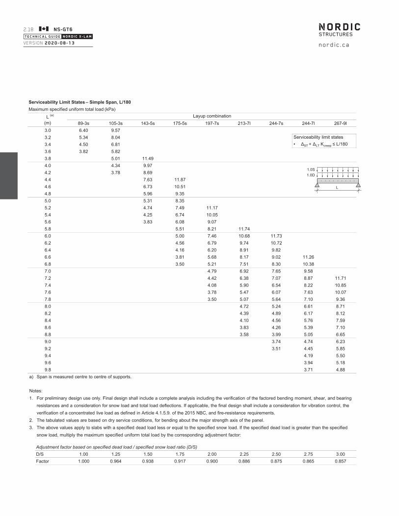
Serviceability Limit States ‒ Simple Span, L/180Maximum specified uniform total load (kPa)
89-3s 105-3s 143-5s 175-5s 197-7s 213-7l 244-7s 244-7l 267-9l3.0 6.40 9.573.2 5.34 8.043.4 4.50 6.813.6 3.82 5.823.8 5.01 11.494.0 4.34 9.974.2 3.78 8.694.4 7.63 11.874.6 6.73 10.514.8 5.96 9.355.0 5.31 8.355.2 4.74 7.49 11.175.4 4.25 6.74 10.055.6 3.83 6.08 9.075.8 5.51 8.21 11.746.0 5.00 7.46 10.68 11.736.2 4.56 6.79 9.74 10.726.4 4.16 6.20 8.91 9.826.6 3.81 5.68 8.17 9.02 11.266.8 3.50 5.21 7.51 8.30 10.387.0 4.79 6.92 7.65 9.587.2 4.42 6.38 7.07 8.87 11.717.4 4.08 5.90 6.54 8.22 10.857.6 3.78 5.47 6.07 7.63 10.077.8 3.50 5.07 5.64 7.10 9.368.0 4.72 5.24 6.61 8.718.2 4.39 4.89 6.17 8.128.4 4.10 4.56 5.76 7.598.6 3.83 4.26 5.39 7.108.8 3.58 3.99 5.05 6.659.0 3.74 4.74 6.239.2 3.51 4.45 5.859.4 4.19 5.509.6 3.94 5.189.8 3.71 4.88
Adjustment factor based on specified dead load / specified snow load ratio (D/S)D/S 1.00 1.25 1.50 1.75 2.00 2.25 2.50 2.75 3.00Factor 1.000 0.964 0.938 0.917 0.900 0.886 0.875 0.865 0.857
L (a)
(m)Layup combination
Notes:1. For preliminary design use only. Final design shall include a complete analysis including the verification of the factored bending moment, shear, and bearing
resistances and a consideration for snow load and total load deflections. If applicable, the final design shall include a consideration for vibration control, the verification of a concentrated live load as defined in Article 4.1.5.9. of the 2015 NBC, and fire-resistance requirements.
2. The tabulated values are based on dry service conditions, for bending about the major strength axis of the panel. 3. The above values apply to slabs with a specified dead load less or equal to the specified snow load. If the specified dead load is greater than the specified
snow load, multiply the maximum specified uniform total load by the corresponding adjustment factor:
a) Span is measured centre to centre of supports.
Serviceability limit states• ΔST + ΔLT Kcreep ≤ L/180
1.0D1.0S
L

nordic .ca
NS-GT6 2.19T E C H N I C A L G U I D E N O R D I C X- L A M
VERSION 2020-08-13
Serviceability Limit States ‒ L/180, Double SpanMaximum specified uniform total load (kPa)
89-3s 105-3s 143-5s 175-5s 197-7s 213-7l 244-7s 244-7l 267-9l3.03.2 10.463.4 8.903.6 7.63 11.133.8 6.58 9.684.0 5.72 8.464.2 5.00 7.444.4 4.39 6.574.6 3.87 5.834.8 5.19 11.865.0 4.64 10.625.2 4.16 9.545.4 3.75 8.605.6 7.78 11.925.8 7.06 10.866.0 6.42 9.926.2 5.86 9.086.4 5.36 8.336.6 4.91 7.66 11.436.8 4.51 7.06 10.537.0 4.15 6.52 9.727.2 3.83 6.03 8.997.4 3.54 5.59 8.33 11.827.6 5.19 7.74 10.99 11.977.8 4.82 7.19 10.24 11.178.0 4.49 6.70 9.55 10.438.2 4.19 6.25 8.92 9.768.4 3.92 5.84 8.34 9.14 11.328.6 3.66 5.46 7.81 8.57 10.648.8 5.11 7.33 8.05 10.009.0 4.80 6.88 7.57 9.429.2 4.50 6.47 7.12 8.87 11.769.4 4.24 6.09 6.71 8.37 11.099.6 3.99 5.74 6.33 7.91 10.469.8 3.76 5.41 5.98 7.47 9.88
Adjustment factor based on specified dead load / specified snow load ratio (D/S)D/S 1.00 1.25 1.50 1.75 2.00 2.25 2.50 2.75 3.00Factor 1.000 0.964 0.938 0.917 0.900 0.886 0.875 0.865 0.857
L (a)
(m)Layup combination
Notes:1. For preliminary design use only. Final design shall include a complete analysis including the verification of the factored bending moment, shear, and bearing
resistances and a consideration for snow load and total load deflections. If applicable, the final design shall include a consideration for vibration control, the verification of a concentrated live load as defined in Article 4.1.5.9. of the 2015 NBC, and fire-resistance requirements.
2. The tabulated values are based on dry service conditions, for bending about the major strength axis of the panel. 3. The above values apply to slabs with a specified dead load less or equal to the specified snow load. If the specified dead load is greater than the specified
snow load, multiply the maximum specified uniform total load by the corresponding adjustment factor:
a) Span is measured centre to centre of supports.
Serviceability limit states• ΔST + ΔLT Kcreep ≤ L/180
100 % 50 %
1.0D1.0S
LL

nordic .ca
2.20 NS-GT6 T E C H N I C A L G U I D E N O R D I C X- L A M
VERSION 2020-08-13
Serviceability Limit States ‒ L/240, Simple SpanMaximum specified uniform snow load (kPa)
89-3s 105-3s 143-5s 175-5s 197-7s 213-7l 244-7s 244-7l 267-9l3.0 7.203.2 6.01 9.053.4 5.06 7.673.6 4.30 6.553.8 3.69 5.644.0 3.18 4.884.2 2.77 4.26 9.794.4 2.42 3.73 8.594.6 2.12 3.29 7.574.8 2.91 6.715.0 2.59 5.97 9.405.2 2.31 5.34 8.435.4 2.08 4.79 7.595.6 4.32 6.855.8 3.90 6.20 9.246.0 3.53 5.64 8.406.2 3.21 5.13 7.656.4 2.93 4.69 6.986.6 2.68 4.29 6.40 9.206.8 2.46 3.94 5.87 8.45 9.347.0 2.26 3.63 5.40 7.79 8.617.2 2.08 3.34 4.98 7.19 7.96 9.987.4 1.92 3.09 4.60 6.65 7.37 9.257.6 2.86 4.26 6.16 6.83 8.597.8 2.65 3.95 5.71 6.35 7.998.0 2.47 3.67 5.31 5.91 7.44 9.818.2 2.29 3.41 4.95 5.50 6.94 9.158.4 2.14 3.18 4.62 5.14 6.49 8.548.6 2.00 2.97 4.31 4.80 6.07 7.998.8 2.78 4.04 4.50 5.69 7.489.0 2.60 3.78 4.22 5.34 7.029.2 2.44 3.55 3.96 5.01 6.599.4 2.29 3.33 3.72 4.71 6.209.6 2.15 3.13 3.50 4.44 5.839.8 2.03 2.95 3.30 4.18 5.50
L (a)
(m)Layup combination
Notes:1. For preliminary design use only. Final design shall include a complete analysis including the verification of the factored bending moment, shear, and bearing
resistances and a consideration for snow load and total load deflections. If applicable, the final design shall include a consideration for vibration control, the verification of a concentrated live load as defined in Article 4.1.5.9. of the 2015 NBC, and fire-resistance requirements.
2. The tabulated values are based on dry service conditions, for bending about the major strength axis of the panel.
a) Span is measured centre to centre of supports.
Serviceability limit states• ΔS ≤ L/240
1.0S
L

nordic .ca
NS-GT6 2.21T E C H N I C A L G U I D E N O R D I C X- L A M
VERSION 2020-08-13
Serviceability Limit States ‒ L/240, Double SpanMaximum specified uniform snow load (kPa)
89-3s 105-3s 143-5s 175-5s 197-7s 213-7l 244-7s 244-7l 267-9l3.03.23.4 8.543.6 7.303.8 6.29 9.354.0 5.45 8.154.2 4.75 7.154.4 4.17 6.304.6 3.68 5.584.8 3.26 4.965.0 2.90 4.435.2 2.59 3.97 9.115.4 2.32 3.57 8.205.6 2.09 3.22 7.415.8 2.92 6.716.0 2.65 6.10 9.516.2 2.41 5.56 8.696.4 2.20 5.08 7.976.6 2.02 4.65 7.326.8 4.27 6.747.0 3.93 6.21 9.267.2 3.63 5.74 8.567.4 3.35 5.32 7.927.6 3.10 4.93 7.357.8 2.88 4.58 6.83 9.768.0 2.68 4.27 6.35 9.10 9.998.2 2.49 3.98 5.92 8.49 9.348.4 2.32 3.71 5.53 7.94 8.748.6 2.17 3.47 5.17 7.43 8.198.8 2.03 3.25 4.84 6.96 7.68 9.599.0 3.05 4.54 6.53 7.22 9.029.2 2.86 4.26 6.14 6.79 8.499.4 2.69 4.00 5.77 6.39 8.019.6 2.53 3.77 5.44 6.02 7.55 9.989.8 2.39 3.55 5.13 5.68 7.14 9.42
L (a)
(m)Layup combination
Notes:1. For preliminary design use only. Final design shall include a complete analysis including the verification of the factored bending moment, shear, and bearing
resistances and a consideration for snow load and total load deflections. If applicable, the final design shall include a consideration for vibration control, the verification of a concentrated live load as defined in Article 4.1.5.9. of the 2015 NBC, and fire-resistance requirements.
2. The tabulated values are based on dry service conditions, for bending about the major strength axis of the panel.
a) Span is measured centre to centre of supports.
Serviceability limit states• ΔS ≤ L/240
100 % 50 %1.0S
LL
nordic .ca
2.22 NS-GT6 T E C H N I C A L G U I D E N O R D I C X- L A M
VERSION 2020-08-13
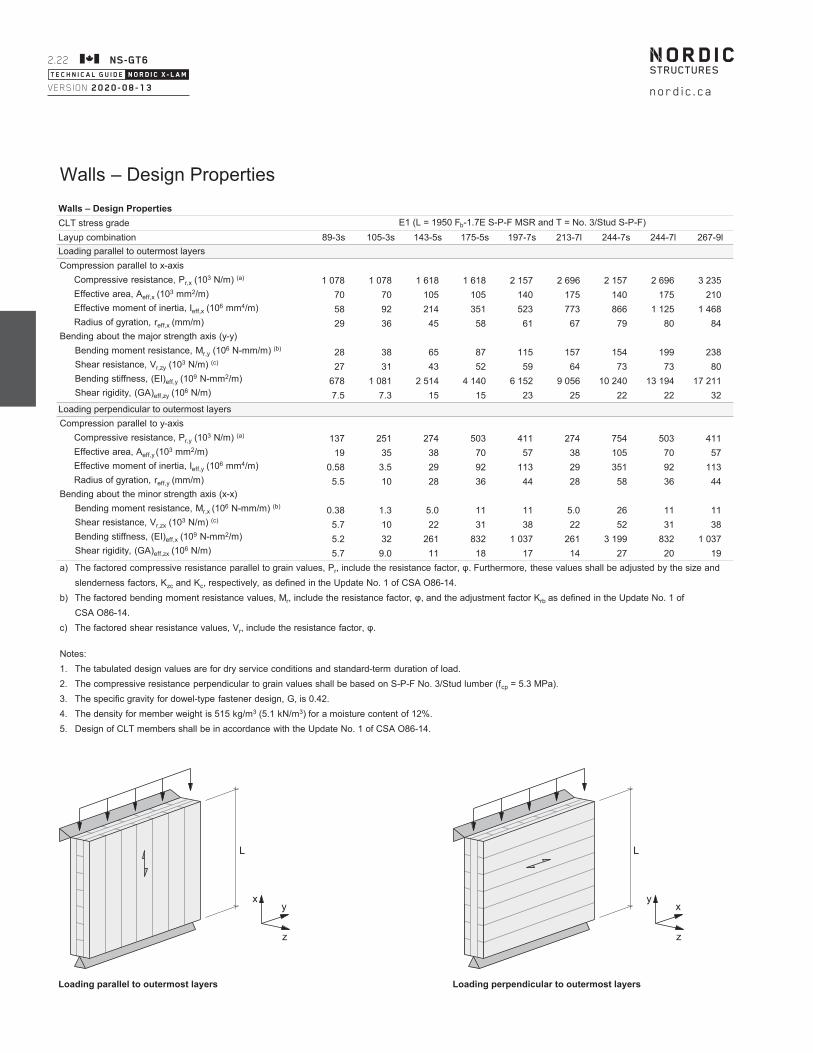
Walls ‒ Design PropertiesWalls – Design PropertiesCLT stress grade E1 (L = 1950 Fb-1.7E S-P-F MSR and T = No. 3/Stud S-P-F)Layup combination 89-3s 105-3s 143-5s 175-5s 197-7s 213-7l 244-7s 244-7l 267-9l
1 078 1 078 1 618 1 618 2 157 2 696 2 157 2 696 3 23570 70 105 105 140 175 140 175 21058 92 214 351 523 773 866 1 125 1 46829 36 45 58 61 67 79 80 84
28 38 65 87 115 157 154 199 23827 31 43 52 59 64 73 73 80
678 1 081 2 514 4 140 6 152 9 056 10 240 13 194 17 2117.5 7.3 15 15 23 25 22 22 32
137 251 274 503 411 274 754 503 41119 35 38 70 57 38 105 70 57
0.58 3.5 29 92 113 29 351 92 1135.5 10 28 36 44 28 58 36 44
0.38 1.3 5.0 11 11 5.0 26 11 115.7 10 22 31 38 22 52 31 385.2 32 261 832 1 037 261 3 199 832 1 0375.7 9.0 11 18 17 14 27 20 19
Loading parallel to outermost layers Loading perpendicular to outermost layers
Loading parallel to outermost layers
Loading perpendicular to outermost layers
a) The factored compressive resistance parallel to grain values, Pr, include the resistance factor, φ. Furthermore, these values shall be adjusted by the size and slenderness factors, Kzc and Kc, respectively, as defined in the Update No. 1 of CSA O86-14.
b) The factored bending moment resistance values, Mr, include the resistance factor, φ, and the adjustment factor Krb as defined in the Update No. 1 ofCSA O86-14.
c) The factored shear resistance values, Vr, include the resistance factor, φ.
Notes:1. The tabulated design values are for dry service conditions and standard-term duration of load. 2. The compressive resistance perpendicular to grain values shall be based on S-P-F No. 3/Stud lumber (fcp = 5.3 MPa).3. The specific gravity for dowel-type fastener design, G, is 0.42.4. The density for member weight is 515 kg/m3 (5.1 kN/m3) for a moisture content of 12%.5. Design of CLT members shall be in accordance with the Update No. 1 of CSA O86-14.
Compression parallel to x-axisCompressive resistance, Pr,x (103 N/m) (a)
Effective area, Aeff,x (103 mm2/m)Effective moment of inertia, Ieff,x (106 mm4/m)Radius of gyration, reff,x (mm/m)
Bending about the major strength axis (y-y)Bending moment resistance, Mr,y (106 N-mm/m) (b)
Shear resistance, Vr,zy (103 N/m) (c)
Bending stiffness, (EI)eff,y (109 N-mm2/m)Shear rigidity, (GA)eff,zy (106 N/m)
Compression parallel to y-axisCompressive resistance, Pr,y (103 N/m) (a)
Effective area, Aeff,y (103 mm2/m)Effective moment of inertia, Ieff,y (106 mm4/m)Radius of gyration, reff,y (mm/m)
Bending about the minor strength axis (x-x)Bending moment resistance, Mr,x (106 N-mm/m) (b)
Shear resistance, Vr,zx (103 N/m) (c)
Bending stiffness, (EI)eff,x (109 N-mm2/m)Shear rigidity, (GA)eff,zx (106 N/m)
z
yx
L
z
xy
L

nordic .ca
NS-GT6 2.23T E C H N I C A L G U I D E N O R D I C X- L A M
VERSION 2020-08-13
Walls ‒ Selection TablesUltimate Limit States ‒ Concentric End LoadsMaximum factored uniform load, Pf (kN/m)
L Fire-resistance rating
(m) (min) 89-3s 105-3s 143-5s 175-5s 197-7s 213-7l 244-7s 244-7l 267-9l0 632 846 1 495 1 639 2 209 2 795 2 257 2 822 3 38730 342 628 1 495 1 639 2 209 2 795 2 257 2 822 3 38760 45 50 1 347 1 639 2 209 2 795 2 257 2 822 3 38790 393 1 490 2 072 2 795 2 257 2 822 3 387120 49 165 1 366 2 114 2 007 2 822 3 3870 452 664 1 270 1 484 2 022 2 593 2 135 2 675 3 22130 211 415 1 270 1 484 2 022 2 593 2 135 2 675 3 22160 25 28 946 1 467 2 022 2 593 2 135 2 675 3 22190 246 1 118 1 586 2 322 2 135 2 675 3 221120 27 99 968 1 571 1 595 2 675 3 2210 324 513 1 057 1 324 1 825 2 379 2 006 2 520 3 04830 137 282 1 057 1 324 1 825 2 379 2 006 2 520 3 04860 15 17 670 1 121 1 825 2 379 2 006 2 520 3 04890 161 832 1 200 1 803 2 006 2 298 3 048120 16 62 689 1 160 1 246 2 298 3 0480 235 394 867 1 164 1 626 2 157 1 872 2 357 2 86730 93 198 857 1 164 1 626 2 157 1 872 2 357 2 86760 482 854 1 626 2 157 1 872 2 357 2 86790 109 621 907 1 393 1 872 1 864 2 867120 40 498 861 967 1 864 2 5980 304 706 1 011 1 432 1 936 1 732 2 188 2 67830 142 649 1 011 1 432 1 936 1 732 2 188 2 67860 354 655 1 432 1 875 1 732 2 188 2 67890 76 468 691 1 079 1 732 1 503 2 678120 27 366 647 751 1 503 2 1500 236 574 871 1 249 1 721 1 590 2 016 2 48330 104 498 871 1 249 1 721 1 590 2 016 2 48360 265 507 1 224 1 522 1 590 2 016 2 48390 55 357 533 842 1 590 1 211 2 393120 17 274 493 588 1 211 1 7720 467 745 1 082 1 518 1 450 1 844 2 28830 387 733 1 082 1 518 1 450 1 844 2 28860 203 397 988 1 239 1 450 1 844 2 28890 40 277 415 663 1 345 979 2 014120 11 209 381 464 979 1 459
Adjustment factor based on specified dead load / specified live load ratio (D/L)1.00 1.25 1.50 1.75 2.00 2.25 2.50 2.75 3.001.000 0.952 0.912 0.878 0.849 0.824 0.801 0.780 0.761
5.0
5.5
D/LFactor
Layup combination
2.5
3.0
3.5
4.0
4.5
Notes:1. For preliminary design use only. Final design shall include a complete analysis including the verification of the factored bearing resistance and a
consideration for live load and total load deflections.2. The tabulated values are based on dry service conditions, standard-term duration of load, and on simply axially loaded walls subjected to concentric end
loads parallel to outermost layers.3. For L ≤ 2.5 m, use Pf for L = 2.5 m. 4. L = unsupported length.5. Provided that surfaces are protected from fire exposure by fire-rated Type X gypsum board, the assigned fire-resistance duration can be increased as per
Clause B.8.1 of the Update No. 1 of CSA O86-14.6. The above values apply to wall panels with a specified dead load less or equal to the specified live load. If the specified dead load is greater than the
specified live load, multiply the maximum factored uniform load, Pf, by the corresponding adjustment factor:
L
h
Pf
nordic .ca
2.24 NS-GT6 T E C H N I C A L G U I D E N O R D I C X- L A M
VERSION 2020-08-13
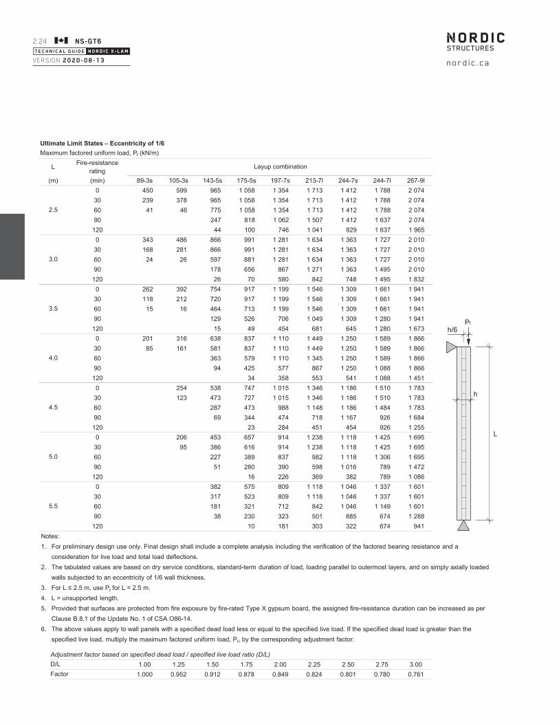
Ultimate Limit States ‒ Eccentricity of 1/6Maximum factored uniform load, Pf (kN/m)
L Fire-resistance rating
(m) (min) 89-3s 105-3s 143-5s 175-5s 197-7s 213-7l 244-7s 244-7l 267-9l0 450 599 965 1 058 1 354 1 713 1 412 1 788 2 07430 239 378 965 1 058 1 354 1 713 1 412 1 788 2 07460 41 46 775 1 058 1 354 1 713 1 412 1 788 2 07490 247 818 1 062 1 507 1 412 1 637 2 074120 44 100 746 1 041 829 1 637 1 9650 343 486 866 991 1 281 1 634 1 363 1 727 2 01030 168 281 866 991 1 281 1 634 1 363 1 727 2 01060 24 26 597 881 1 281 1 634 1 363 1 727 2 01090 178 656 867 1 271 1 363 1 495 2 010120 26 70 580 842 748 1 495 1 8320 262 392 754 917 1 199 1 546 1 309 1 661 1 94130 118 212 720 917 1 199 1 546 1 309 1 661 1 94160 15 16 464 713 1 199 1 546 1 309 1 661 1 94190 129 526 706 1 049 1 309 1 280 1 941120 15 49 454 681 645 1 280 1 6730 201 316 638 837 1 110 1 449 1 250 1 589 1 86630 85 161 581 837 1 110 1 449 1 250 1 589 1 86660 363 579 1 110 1 345 1 250 1 589 1 86690 94 425 577 867 1 250 1 088 1 866120 34 358 553 541 1 088 1 4510 254 538 747 1 015 1 346 1 186 1 510 1 78330 123 473 727 1 015 1 346 1 186 1 510 1 78360 287 473 988 1 148 1 186 1 484 1 78390 69 344 474 718 1 167 926 1 684120 23 284 451 454 926 1 2550 206 453 657 914 1 238 1 118 1 425 1 69530 95 386 616 914 1 238 1 118 1 425 1 69560 227 389 837 982 1 118 1 306 1 69590 51 280 390 598 1 016 789 1 472120 16 226 369 382 789 1 0860 382 575 809 1 118 1 046 1 337 1 60130 317 523 809 1 118 1 046 1 337 1 60160 181 321 712 842 1 046 1 149 1 60190 38 230 323 501 885 674 1 288120 10 181 303 322 674 941
Adjustment factor based on specified dead load / specified live load ratio (D/L)1.00 1.25 1.50 1.75 2.00 2.25 2.50 2.75 3.001.000 0.952 0.912 0.878 0.849 0.824 0.801 0.780 0.761
5.0
5.5
D/LFactor
Layup combination
2.5
3.0
3.5
4.0
4.5
Notes:1. For preliminary design use only. Final design shall include a complete analysis including the verification of the factored bearing resistance and a
consideration for live load and total load deflections.2. The tabulated values are based on dry service conditions, standard-term duration of load, loading parallel to outermost layers, and on simply axially loaded
walls subjected to an eccentricity of 1/6 wall thickness.3. For L ≤ 2.5 m, use Pf for L = 2.5 m. 4. L = unsupported length.5. Provided that surfaces are protected from fire exposure by fire-rated Type X gypsum board, the assigned fire-resistance duration can be increased as per
Clause B.8.1 of the Update No. 1 of CSA O86-14.6. The above values apply to wall panels with a specified dead load less or equal to the specified live load. If the specified dead load is greater than the
specified live load, multiply the maximum factored uniform load, Pf, by the corresponding adjustment factor:
h/6
h
L
Pf
nordic .ca
NS-GT6 2.25T E C H N I C A L G U I D E N O R D I C X- L A M
VERSION 2020-08-13
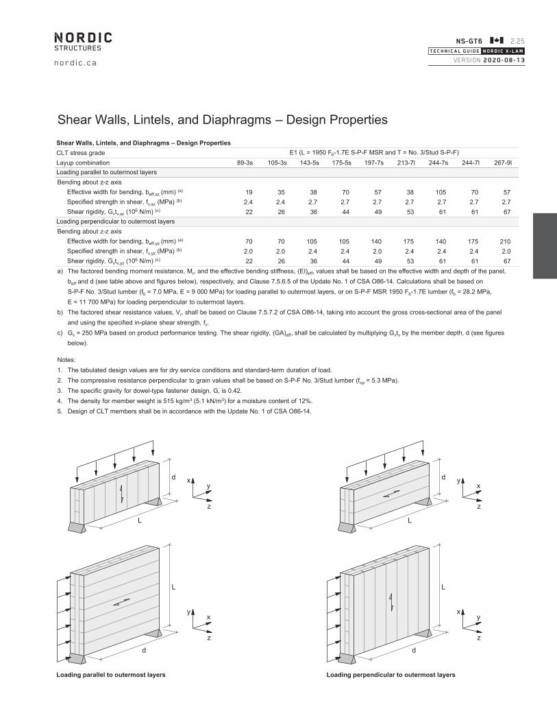
Shear Walls, Lintels, and Diaphragms ‒ Design PropertiesShear Walls, Lintels, and Diaphragms – Design PropertiesCLT stress grade E1 (L = 1950 Fb-1.7E S-P-F MSR and T = No. 3/Stud S-P-F)Layup combination 89-3s 105-3s 143-5s 175-5s 197-7s 213-7l 244-7s 244-7l 267-9l
19 35 38 70 57 38 105 70 572.4 2.4 2.7 2.7 2.7 2.7 2.7 2.7 2.722 26 36 44 49 53 61 61 67
70 70 105 105 140 175 140 175 2102.0 2.0 2.4 2.4 2.0 2.4 2.4 2.4 2.022 26 36 44 49 53 61 61 67
Loading parallel to outermost layers Loading perpendicular to outermost layers
Loading parallel to outermost layers
Loading perpendicular to outermost layers
a) The factored bending moment resistance, Mr, and the effective bending stiffness, (EI)eff, values shall be based on the effective width and depth of the panel, beff and d (see table above and figures below), respectively, and Clause 7.5.6.5 of the Update No. 1 of CSA O86-14. Calculations shall be based on S-P-F No. 3/Stud lumber (fb = 7.0 MPa, E = 9 000 MPa) for loading parallel to outermost layers, or on S-P-F MSR 1950 Fb-1.7E lumber (fb = 28.2 MPa, E = 11 700 MPa) for loading perpendicular to outermost layers.
b) The factored shear resistance values, Vr, shall be based on Clause 7.5.7.2 of CSA O86-14, taking into account the gross cross-sectional area of the panel and using the specified in-plane shear strength, fv.
c) Gv = 250 MPa based on product performance testing. The shear rigidity, (GA)eff, shall be calculated by multiplying Gvtv by the member depth, d (see figures below).
Notes:1. The tabulated design values are for dry service conditions and standard-term duration of load. 2. The compressive resistance perpendicular to grain values shall be based on S-P-F No. 3/Stud lumber (fcp = 5.3 MPa).3. The specific gravity for dowel-type fastener design, G, is 0.42.4. The density for member weight is 515 kg/m3 (5.1 kN/m3) for a moisture content of 12%.5. Design of CLT members shall be in accordance with the Update No. 1 of CSA O86-14.
Bending about z-z axisEffective width for bending, beff,xz (mm) (a)
Specified strength in shear, fv,xz (MPa) (b)
Shear rigidity, Gvtv,xz (106 N/m) (c)
Bending about z-z axisEffective width for bending, beff,yz (mm) (a)
Specified strength in shear, fv,yz (MPa) (b)
Shear rigidity, Gvtv,yz (106 N/m) (c)
z
xy
d
L
d
z
yx
L
z
yx
d
L
z
xy
L
d


VERSION2020-08-13
3
T ECHNIC A L GU IDENOR DIC X-L A M
NS-GT6ENGLISH
STRUCTURAL DETAILS

nordic .ca
3.2 NS-GT6 T E C H N I C A L G U I D E N O R D I C X- L A M
VERSION 2020-08-13
nordic .ca
NS-GT6 3.3T E C H N I C A L G U I D E N O R D I C X- L A M
VERSION 2020-08-13
1.0 General
1.1 This document supersedes all previous versions. For the latest version, consult nordic.ca or contact Nordic Structures.
1.2 The information contained in this document is provided for information purposes only. This information should not be used for any application without examination and verification of its accuracy, suitability and applicability by a licensed engineer, architect or other professional. Nordic Structures does not guarantee that the information is suitable for any general or particular use, and assumes no responsibility for the use, application of and / or reference to the information.
1.3 All dimensions are in millimetres (mm), unless otherwise noted.
1.4 For more information, consult nordic.ca or contact Nordic Structures.
2.0 Design of connections
2.1 The design of connections, including fire resistance if required, shall be in accordance with CSA O86-14, Engineering design in wood.
2.2 The design of connections should include considerations for structural and service performance, such as resistance, minimum distances, dimensional changes, durability, erection and fire safety, among others, as well as taking into account architectural requirements.
2.3 The connections shown in this document are provided for information purposes only, and conceptually. Note that many possibilities and variants are possible.
GENERAL NOTES

nordic .ca
3.4 NS-GT6 T E C H N I C A L G U I D E N O R D I C X- L A M
VERSION 2020-08-13
==
2020-02-01
TITLE
CATEGORY DATE EGAPELACS
Continuous Floor Slab on Beam
-TLC-LG ,erutcurtS
NS-DS2001-CA-enDRAWING
NORDIC X-LAM SLAB
NORDIC LAM BEAM
PARTIALLY THREADED SCREW @ 300 O.C. U.N.O.
= = = =
2020-02-01
TITLE
CATEGORY DATE EGAPELACS
Single Floor Slab on Beam
-TLC-LG ,erutcurtS
NS-DS2002-CA-enDRAWING
NORDIC X-LAM SLAB
NORDIC LAM BEAM
PARTIALLY THREADED SCREWS@ 300 O.C. U.N.O., STAGGERED
Structure, GL-CLT Continuous Floor Slab on Beam NS-DS2001
Structure, GL-CLT Single Floor Slab on Beam NS-DS2002
nordic .ca
NS-GT6 3.5T E C H N I C A L G U I D E N O R D I C X- L A M
VERSION 2020-08-13
==
==
==
=
2020-02-01
(a)
TITLE
CATEGORY DATE EGAPELACS
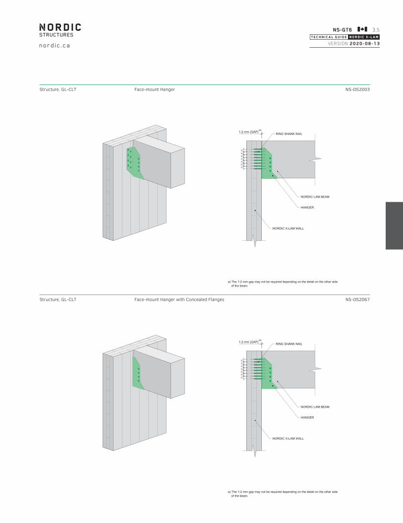
Face-mount Hanger
-TLC-LG ,erutcurtS
NS-DS2003-CA-enDRAWING
1-2 mm (GAP)
NORDIC X-LAM WALL
NORDIC LAM BEAM
HANGER
RING SHANK NAIL
a) The 1-2 mm gap may not be required depending on the detail on the other side of the beam.
==
==
==
=
2020-02-01
(a)
TITLE
CATEGORY DATE EGAPELACS
Face-mount Hanger with Concealed Flanges
-TLC-LG ,erutcurtS
NS-DS2067-CA-enDRAWING
1-2 mm (GAP)
NORDIC X-LAM WALL
NORDIC LAM BEAM
HANGER
RING SHANK NAIL
a) The 1-2 mm gap may not be required depending on the detail on the other side of the beam.
Structure, GL-CLT Face-mount Hanger NS-DS2003
Structure, GL-CLT Face-mount Hanger with Concealed Flanges NS-DS2067
nordic .ca
3.6 NS-GT6 T E C H N I C A L G U I D E N O R D I C X- L A M
VERSION 2020-08-13
==
2020-02-01
TITLE
CATEGORY DATE EGAPELACS
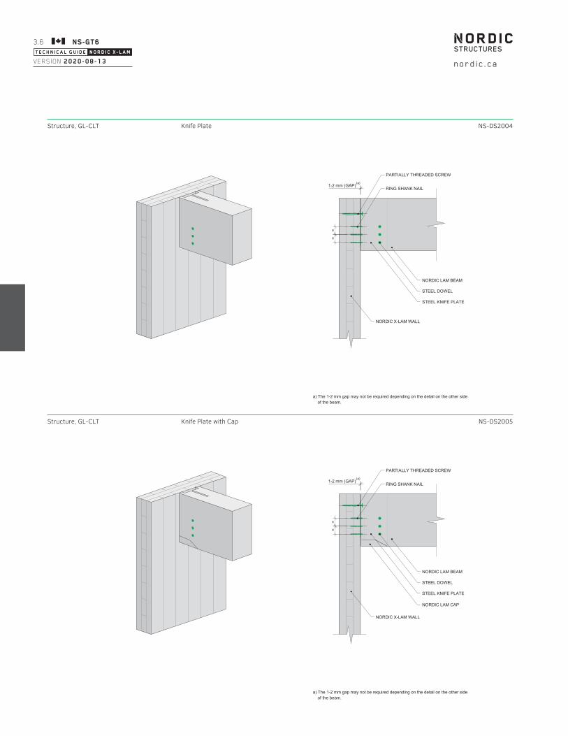
Knife Plate
-TLC-LG ,erutcurtS
NS-DS2004-CA-enDRAWING
(a)
RING SHANK NAIL
NORDIC X-LAM WALL
NORDIC LAM BEAM
STEEL DOWEL
STEEL KNIFE PLATE
1-2 mm (GAP)
a) The 1-2 mm gap may not be required depending on the detail on the other side of the beam.
PARTIALLY THREADED SCREW
==
2020-02-01
TITLE
CATEGORY DATE EGAPELACS
Knife Plate with Cap
-TLC-LG ,erutcurtS
NS-DS2005-CA-enDRAWING
(a)
NORDIC LAM BEAM
STEEL DOWEL
STEEL KNIFE PLATE
NORDIC X-LAM WALL
1-2 mm (GAP)
a) The 1-2 mm gap may not be required depending on the detail on the other side of the beam.
RING SHANK NAIL
PARTIALLY THREADED SCREW
NORDIC LAM CAP
Structure, GL-CLT Knife Plate NS-DS2004
Structure, GL-CLT Knife Plate with Cap NS-DS2005
nordic .ca
NS-GT6 3.7T E C H N I C A L G U I D E N O R D I C X- L A M
VERSION 2020-08-13
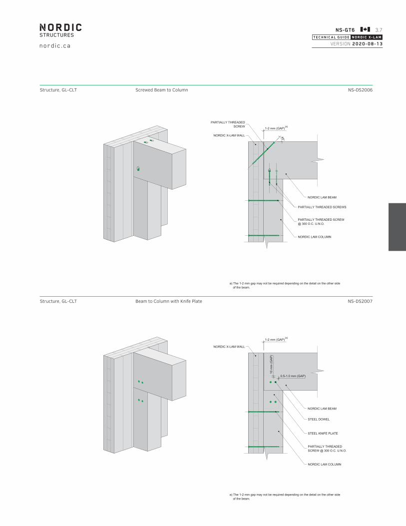
45°
2020-02-01
(a)
TITLE
CATEGORY DATE EGAPELACS
Screwed Beam to Column
-TLC-LG ,erutcurtS
NS-DS2006-CA-enDRAWING
1-2 mm (GAP)
NORDIC X-LAM WALL
NORDIC LAM COLUMN
a) The 1-2 mm gap may not be required depending on the detail on the other side of the beam.
NORDIC LAM BEAM
PARTIALLY THREADED SCREW@ 300 O.C. U.N.O.
PARTIALLY THREADED SCREW
PARTIALLY THREADED SCREWS
2020-02-01
(a)
10 m
m (G
AP
)
0.5-1.0 mm (GAP)
TITLE
CATEGORY DATE EGAPELACS
Beam to Column with Knife Plate
-TLC-LG ,erutcurtS
NS-DS2007-CA-enDRAWING
1-2 mm (GAP)
NORDIC X-LAM WALL
NORDIC LAM COLUMN
STEEL KNIFE PLATE
STEEL DOWEL
a) The 1-2 mm gap may not be required depending on the detail on the other side of the beam.
NORDIC LAM BEAM
PARTIALLY THREADED SCREW @ 300 O.C. U.N.O.
Structure, GL-CLT Screwed Beam to Column NS-DS2006
Structure, GL-CLT Beam to Column with Knife Plate NS-DS2007
nordic .ca
3.8 NS-GT6 T E C H N I C A L G U I D E N O R D I C X- L A M
VERSION 2020-08-13
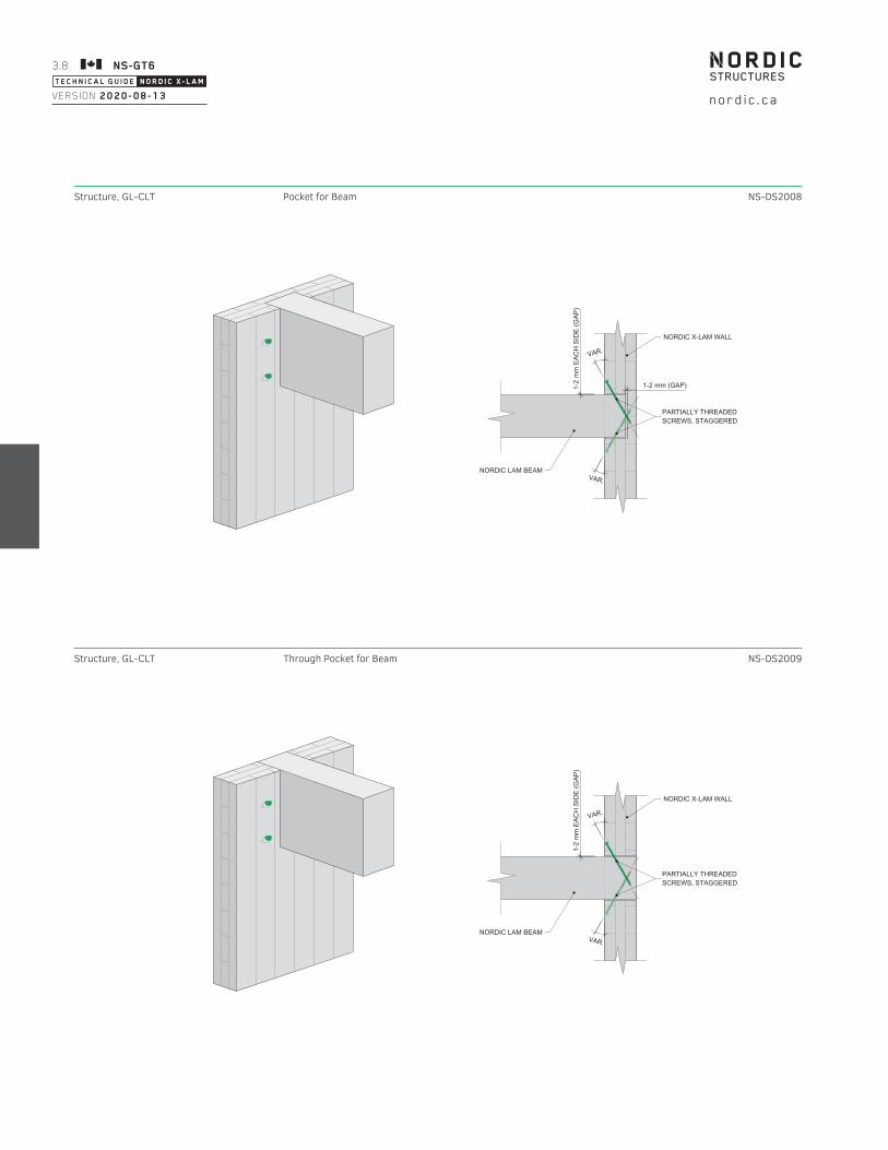
VAR.
VAR.
2020-02-01
1-2
mm
EA
CH
SID
E (G
AP
)
1-2 mm (GAP)
TITLE
CATEGORY DATE EGAPELACS
Structure, GL-CLT
Pocket for Beam
-
NS-DS2008-CA-enDRAWING
NORDIC X-LAM WALL
NORDIC LAM BEAM
PARTIALLY THREADED SCREWS, STAGGERED
VAR.
VAR.
2020-02-01
1-2
mm
EA
CH
SID
E (G
AP
)
NORDIC LAM BEAM
NORDIC X-LAM WALL
TITLE
CATEGORY DATE EGAPELACS
Through Pocket for Beam
-TLC-LG ,erutcurtS
NS-DS2009-CA-enDRAWING
PARTIALLY THREADED SCREWS, STAGGERED
Structure, GL-CLT Pocket for Beam NS-DS2008
Structure, GL-CLT Through Pocket for Beam NS-DS2009

nordic .ca
NS-GT6 3.9T E C H N I C A L G U I D E N O R D I C X- L A M
VERSION 2020-08-13
45°45°
2020-02-01
TITLE
CATEGORY DATE EGAPELACS
Wall to Sill Plate, Screws
-noitadnuoF-llaW ,erutcurtS
NS-DS2010-CA-enDRAWING
CONCRETE
MECHANICAL ANCHOR
NON-SHRINK GROUT 25 mm
IMPERMEABLE MEMBRANE
SILL PLATE
NORDIC X-LAM WALL
PARTIALLY THREADED SCREWS@ 300 O.C. U.N.O., STAGGERED
2020-02-01
TITLE
CATEGORY DATE EGAPELACS
Structure, Wall-Foundation -
NS-DS2011-CA-enDRAWING
Wall to Sill Plate, Nailed Steel Plate
STEEL PLATE
CONCRETE
MECHANICAL ANCHOR
NON-SHRINK GROUT 25 mm
IMPERMEABLE MEMBRANE
SILL PLATE
RING SHANK NAIL
NORDIC X-LAM WALL
Structure, Wall-Foundation Wall to Sill Plate, Screws NS-DS2010
Structure, Wall-Foundation Wall to Sill Plate, Nailed Steel Plate NS-DS2011
nordic .ca
3.10 NS-GT6 T E C H N I C A L G U I D E N O R D I C X- L A M
VERSION 2020-08-13
==
==
==
==
==
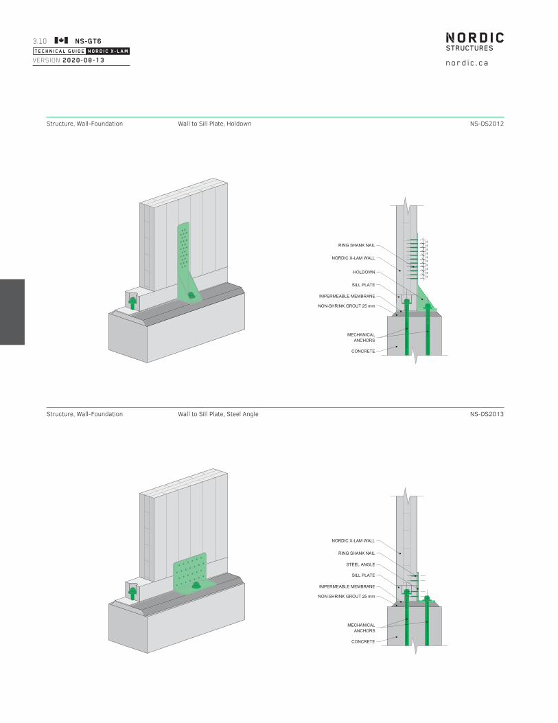
2020-02-01
TITLE
CATEGORY DATE EGAPELACS
Structure, Wall-Foundation -
NS-DS2012-CA-enDRAWING
CONCRETE
RING SHANK NAIL
NORDIC X-LAM WALL
HOLDOWN
SILL PLATE
IMPERMEABLE MEMBRANE
NON-SHRINK GROUT 25 mm
Wall to Sill Plate, Holdown
MECHANICAL ANCHORS
2020-02-01
TITLE
CATEGORY DATE EGAPELACS
Structure, Wall-Foundation -
NS-DS2013-CA-enDRAWING
CONCRETE
NORDIC X-LAM WALL
RING SHANK NAIL
STEEL ANGLE
SILL PLATE
IMPERMEABLE MEMBRANE
NON-SHRINK GROUT 25 mm
Wall to Sill Plate, Steel Angle
MECHANICAL ANCHORS
Structure, Wall-Foundation Wall to Sill Plate, Holdown NS-DS2012
Structure, Wall-Foundation Wall to Sill Plate, Steel Angle NS-DS2013
nordic .ca
NS-GT6 3.11T E C H N I C A L G U I D E N O R D I C X- L A M
VERSION 2020-08-13
==
==
==
==
==
==
==
==
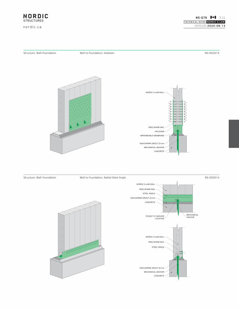
2020-02-01
TITLE
CATEGORY DATE EGAPELACS
-noitadnuoF-llaW ,erutcurtS
NS-DS2014-CA-enDRAWING
NORDIC X-LAM WALL
RING SHANK NAIL
HOLDOWN
NON-SHRINK GROUT 25 mm
MECHANICAL ANCHOR
CONCRETE
Wall to Foundation, Holdown
IMPERMEABLE MEMBRANE
2020-02-01
TITLE
CATEGORY DATE EGAPELACS
Wall to Foundation, Nailed Steel Angle
-noitadnuoF-llaW ,erutcurtS
NS-DS2015-CA-enDRAWING
POCKET AT ANCHOR LOCATION
CONCRETE
NON-SHRINK GROUT 25 mm
STEEL ANGLE
RING SHANK NAIL
NORDIC X-LAM WALL
MECHANICALANCHOR
CONCRETE
NON-SHRINK GROUT 25 mm
STEEL ANGLE
RING SHANK NAIL
NORDIC X-LAM WALL
MECHANICAL ANCHOR
Structure, Wall-Foundation Wall to Foundation, Holdown NS-DS2014
Structure, Wall-Foundation Wall to Foundation, Nailed Steel Angle NS-DS2015
nordic .ca
3.12 NS-GT6 T E C H N I C A L G U I D E N O R D I C X- L A M
VERSION 2020-08-13
2020-02-01
TITLE
CATEGORY DATE EGAPELACS
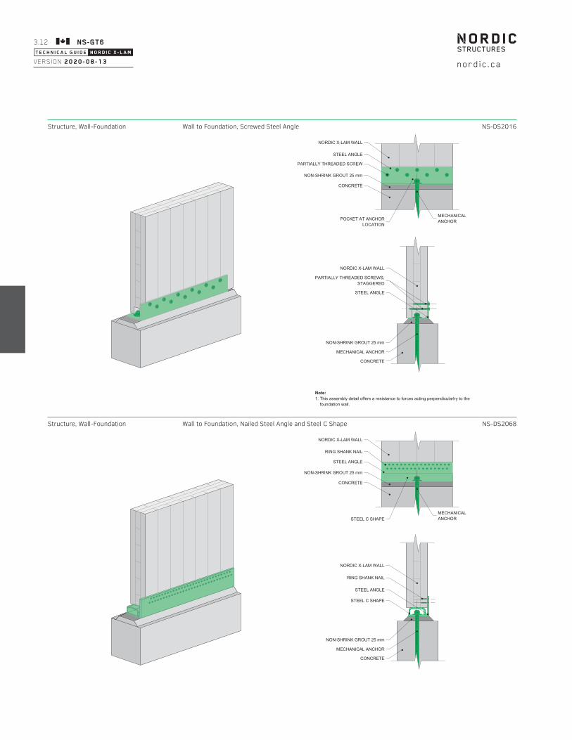
Wall to Foundation, Screwed Steel Angle
-noitadnuoF-llaW ,erutcurtS
NS-DS2016-CA-enDRAWING
POCKET AT ANCHOR LOCATION
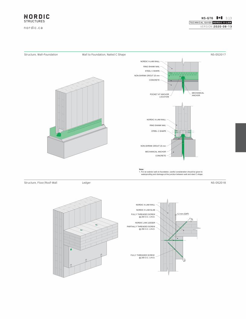
Note:1. This assembly detail offers a resistance to forces acting perpendicularlry to the
foundation wall.
MECHANICALANCHOR
NORDIC X-LAM WALL
STEEL ANGLE
NON-SHRINK GROUT 25 mm
CONCRETE
NORDIC X-LAM WALL
STEEL ANGLE
NON-SHRINK GROUT 25 mm
CONCRETE
MECHANICAL ANCHOR
PARTIALLY THREADED SCREW
PARTIALLY THREADED SCREWS, STAGGERED
2020-02-01
TITLE
CATEGORY DATE EGAPELACS
Wall to Foundation, Nailed Steel Angle and Steel C Shape
-noitadnuoF-llaW ,erutcurtS
NS-DS2068-CA-enDRAWING
CONCRETE
NON-SHRINK GROUT 25 mm
STEEL ANGLE
RING SHANK NAIL
NORDIC X-LAM WALL
MECHANICALANCHOR
CONCRETE
NON-SHRINK GROUT 25 mm
STEEL ANGLE
RING SHANK NAIL
NORDIC X-LAM WALL
MECHANICAL ANCHOR
STEEL C SHAPE
STEEL C SHAPE
Structure, Wall-Foundation Wall to Foundation, Screwed Steel Angle NS-DS2016
Structure, Wall-Foundation Wall to Foundation, Nailed Steel Angle and Steel C Shape NS-DS2068
nordic .ca
NS-GT6 3.13T E C H N I C A L G U I D E N O R D I C X- L A M
VERSION 2020-08-13
2020-02-01
TITLE
CATEGORY DATE EGAPELACS
Wall to Foundation, Nailed C Shape
-noitadnuoF-llaW ,erutcurtS
NS-DS2017-CA-enDRAWING
POCKET AT ANCHOR LOCATION
CONCRETE
MECHANICAL ANCHOR
NON-SHRINK GROUT 25 mm
STEEL C SHAPE
RING SHANK NAIL
NORDIC X-LAM WALL
CONCRETE
NON-SHRINK GROUT 25 mm
STEEL C SHAPE
RING SHANK NAIL
NORDIC X-LAM WALL
Note:1. For an exterior wall on foundation, careful consideration should be given to
waterproofing and drainage at the junction between wall and steel C shape.
MECHANICALANCHOR
45°
45°
2020-02-01
1-2 mm (GAP)
TITLE
CATEGORY DATE EGAPELACS
Ledger
-llaW-fooR/roolF ,erutcurtS
NS-DS2018-CA-enDRAWING
NORDIC X-LAM WALL
NORDIC X-LAM SLAB
NORDIC LAM LEDGER
FULLY THREADED SCREW @ 250 O.C. U.N.O.
FULLY THREADED SCREW@ 250 O.C. U.N.O.
PARTIALLY THREADED SCREW@ 250 O.C. U.N.O.
Structure, Wall-Foundation Wall to Foundation, Nailed C Shape NS-DS2017
Structure, Floor/Roof-Wall Ledger NS-DS2018

nordic .ca
3.14 NS-GT6 T E C H N I C A L G U I D E N O R D I C X- L A M
VERSION 2020-08-13
2020-02-01
TITLE
CATEGORY DATE EGAPELACS
Steel Angle
-llaW-fooR/roolF ,erutcurtS
NS-DS2019-CA-enDRAWING
STEEL ANGLE
RING SHANK NAIL
NORDIC X-LAM SLAB
NORDIC X-LAM WALL
1-2 mm (GAP)
PARTIALLY THREADED SCREW @ 250 O.C. U.N.O.
= =
2020-02-01
TITLE
CATEGORY DATE EGAPELACS
Screwed Floor/Roof Slab to Wall
-llaW-fooR/roolF ,erutcurtS
NS-DS2020-CA-enDRAWING
NORDIC X-LAM SLAB
NORDIC X-LAM WALL
PARTIALLY THREADED SCREW@ 300 O.C. U.N.O.
Structure, Floor/Roof-Wall Steel Angle NS-DS2019
Structure, Floor/Roof-Wall Screwed Floor/Roof Slab to Wall NS-DS2020
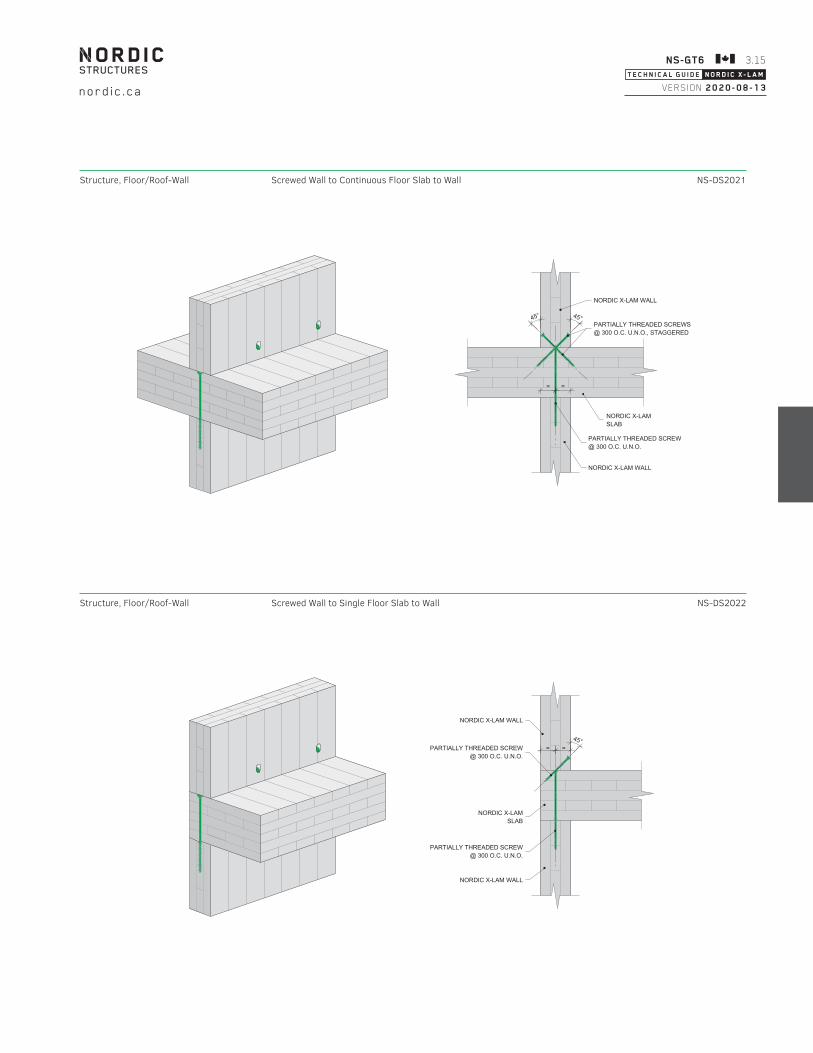
nordic .ca
NS-GT6 3.15T E C H N I C A L G U I D E N O R D I C X- L A M
VERSION 2020-08-13
= =
45°45°
2020-02-01
TITLE
CATEGORY DATE EGAPELACS
Screwed Wall to Continuous Floor Slab to Wall
-llaW-fooR/roolF ,erutcurtS
NS-DS2021-CA-enDRAWING
NORDIC X-LAM SLAB
NORDIC X-LAM WALL
NORDIC X-LAM WALL
PARTIALLY THREADED SCREW@ 300 O.C. U.N.O.
PARTIALLY THREADED SCREWS @ 300 O.C. U.N.O., STAGGERED
45°= =
2020-02-01
TITLE
CATEGORY DATE EGAPELACS
Screwed Wall to Single Floor Slab to Wall
-llaW-fooR/roolF ,erutcurtS
NS-DS2022-CA-enDRAWING
NORDIC X-LAM WALL
NORDIC X-LAM WALL
NORDIC X-LAMSLAB
PARTIALLY THREADED SCREW@ 300 O.C. U.N.O.
PARTIALLY THREADED SCREW@ 300 O.C. U.N.O.
Structure, Floor/Roof-Wall Screwed Wall to Continuous Floor Slab to Wall NS-DS2021
Structure, Floor/Roof-Wall Screwed Wall to Single Floor Slab to Wall NS-DS2022
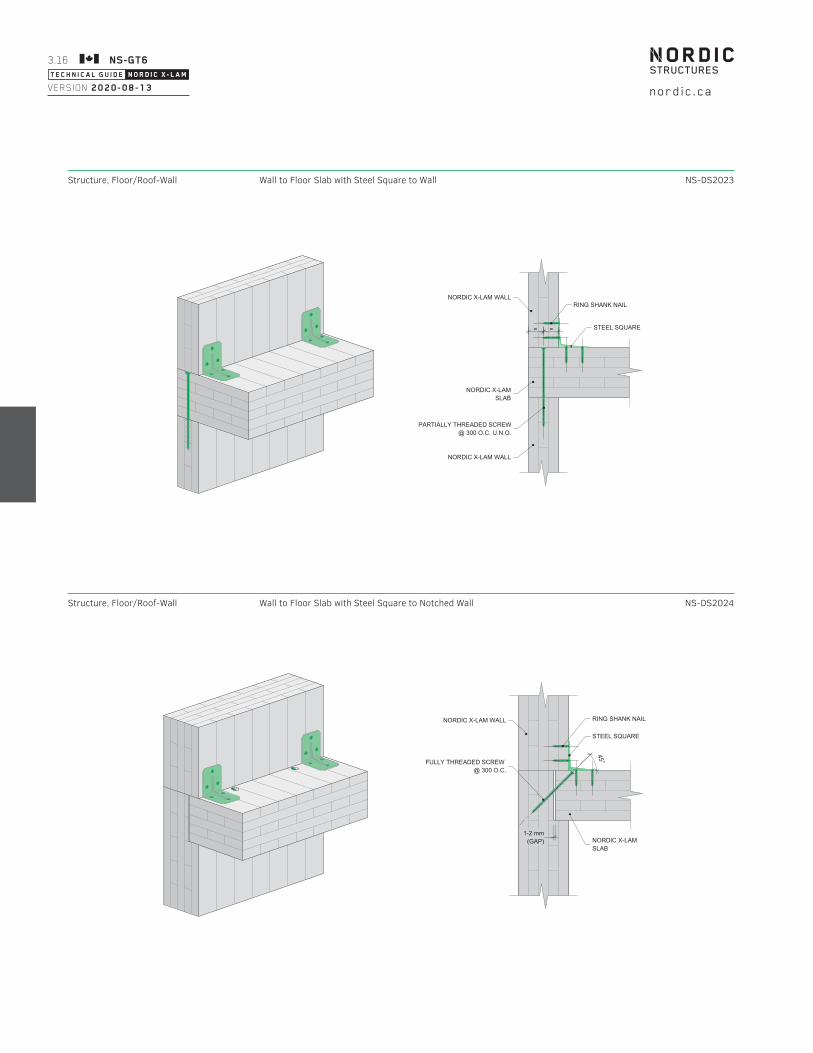
nordic .ca
3.16 NS-GT6 T E C H N I C A L G U I D E N O R D I C X- L A M
VERSION 2020-08-13
= =
2020-02-01
TITLE
CATEGORY DATE EGAPELACS
Wall to Floor Slab with Steel Square to Wall
-llaW-fooR/roolF ,erutcurtS
NS-DS2023-CA-enDRAWING
NORDIC X-LAMSLAB
STEEL SQUARE
RING SHANK NAILNORDIC X-LAM WALL
NORDIC X-LAM WALL
PARTIALLY THREADED SCREW@ 300 O.C. U.N.O.
45°
2020-02-01
TITLE
CATEGORY DATE EGAPELACS
Wall to Floor Slab with Steel Square to Notched Wall
-llaW-fooR/roolF ,erutcurtS
NS-DS2024-CA-enDRAWING
NORDIC X-LAMSLAB
NORDIC X-LAM WALL RING SHANK NAIL
STEEL SQUARE
1-2 mm(GAP)
FULLY THREADED SCREW @ 300 O.C.
Structure, Floor/Roof-Wall Wall to Floor Slab with Steel Square to Wall NS-DS2023
Structure, Floor/Roof-Wall Wall to Floor Slab with Steel Square to Notched Wall NS-DS2024
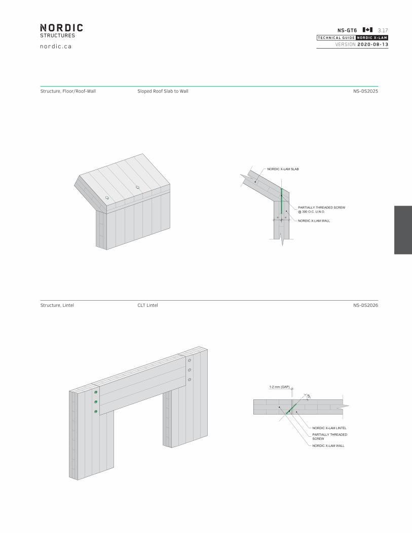
nordic .ca
NS-GT6 3.17T E C H N I C A L G U I D E N O R D I C X- L A M
VERSION 2020-08-13
= =
2020-02-01
TITLE
CATEGORY DATE EGAPELACS
Sloped Roof Slab to Wall
-llaW-fooR/roolF ,erutcurtS
NS-DS2025-CA-enDRAWING
NORDIC X-LAM SLAB
NORDIC X-LAM WALL
PARTIALLY THREADED SCREW@ 300 O.C. U.N.O.
45°
2020-02-01
1-2 mm (GAP)
TITLE
CATEGORY DATE EGAPELACS
CLT Lintel
-letniL ,erutcurtS
NS-DS2026-CA-enDRAWING
NORDIC X-LAM WALL
NORDIC X-LAM LINTEL
PARTIALLY THREADED SCREW
Structure, Floor/Roof-Wall Sloped Roof Slab to Wall NS-DS2025
Structure, Lintel CLT Lintel NS-DS2026
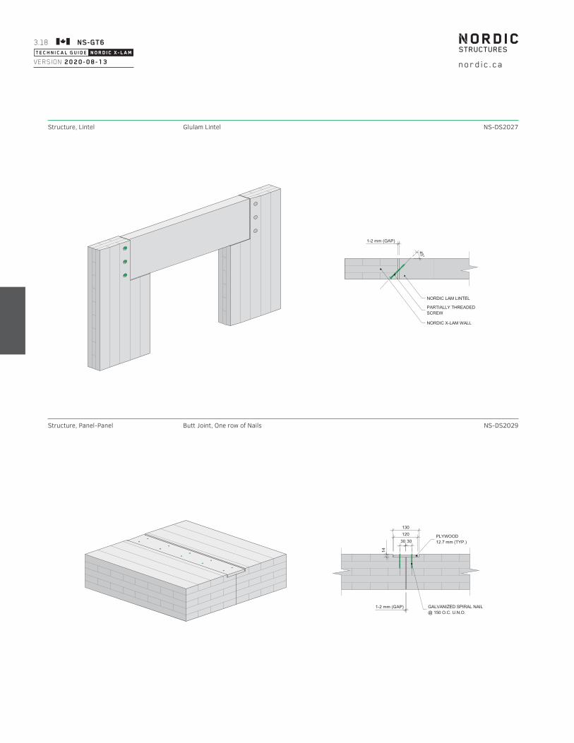
nordic .ca
3.18 NS-GT6 T E C H N I C A L G U I D E N O R D I C X- L A M
VERSION 2020-08-13
45°
2020-02-01
1-2 mm (GAP)
TITLE
CATEGORY DATE EGAPELACS
Glulam Lintel
-letniL ,erutcurtS
NS-DS2027-CA-enDRAWING
NORDIC LAM LINTEL
NORDIC X-LAM WALL
PARTIALLY THREADED SCREW
2020-02-01
1-2 mm (GAP)
TITLE
CATEGORY DATE EGAPELACS
Butt Joint, One row of Nails NS-DS2029-CA-enDRAWING
14
30 30
130120 PLYWOOD
12.7 mm (TYP.)
Structure, Panel-Panel -
GALVANIZED SPIRAL NAIL@ 150 O.C. U.N.O.
Structure, Lintel Glulam Lintel NS-DS2027
Structure, Panel-Panel Butt Joint, One row of Nails NS-DS2029
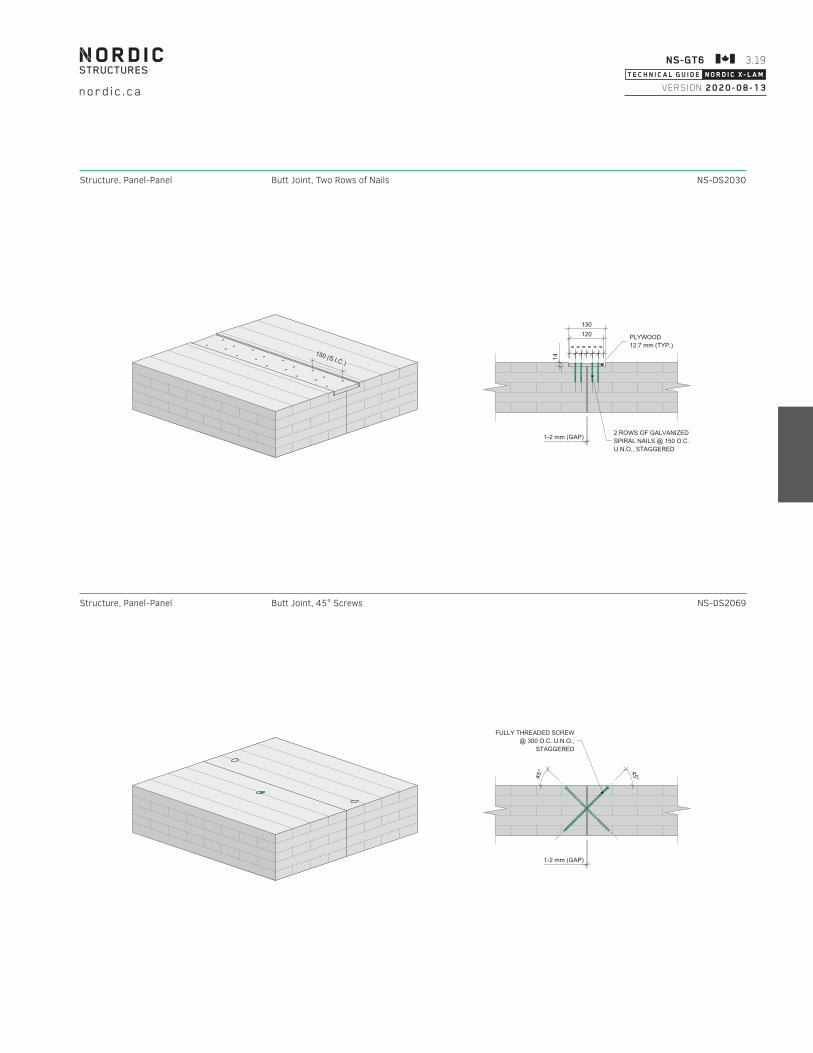
nordic .ca
NS-GT6 3.19T E C H N I C A L G U I D E N O R D I C X- L A M
VERSION 2020-08-13
= = = = = =
2020-02-01
1-2 mm (GAP)
TITLE
CATEGORY DATE EGAPELACS
Butt Joint, Two Rows of Nails NS-DS2030-CA-enDRAWING
14
130120
150 (S.I.C.)
PLYWOOD12.7 mm (TYP.)
Structure, Panel-Panel -
2 ROWS OF GALVANIZED SPIRAL NAILS @ 150 O.C. U.N.O., STAGGERED
45°45°
2020-02-01
TITLE
CATEGORY DATE EGAPELACS
DRAWING
Butt Joint, 45° Screws
-lenaP-lenaP ,erutcurtS
NS-DS2069-CA-en
1-2 mm (GAP)
FULLY THREADED SCREW@ 300 O.C. U.N.O.,
STAGGERED
Structure, Panel-Panel Butt Joint, Two Rows of Nails NS-DS2030
Structure, Panel-Panel Butt Joint, 45° Screws NS-DS2069
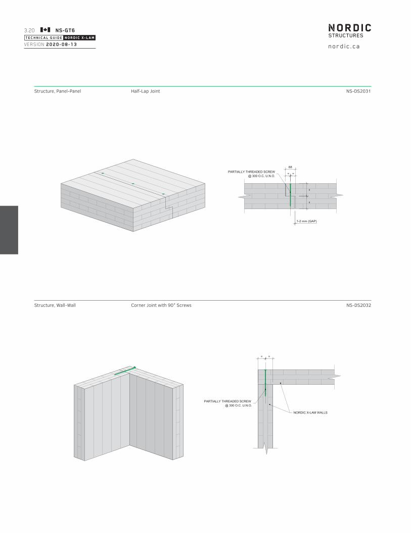
nordic .ca
3.20 NS-GT6 T E C H N I C A L G U I D E N O R D I C X- L A M
VERSION 2020-08-13
==
2020-02-01
1-2 mm (GAP)
TITLE
CATEGORY DATE EGAPELACS
Half-Lap Joint NS-DS2031-CA-enDRAWING
==
68PARTIALLY THREADED SCREW
@ 300 O.C. U.N.O.
Structure, Panel-Panel -
= =
2020-02-01
TITLE
CATEGORY DATE EGAPELACS
Corner Joint with 90° Screws
-llaW-llaW ,erutcurtS
NS-DS2032-CA-enDRAWING
NORDIC X-LAM WALLS
PARTIALLY THREADED SCREW @ 300 O.C. U.N.O.
Structure, Panel-Panel Half-Lap Joint NS-DS2031
Structure, Wall-Wall Corner Joint with 90° Screws NS-DS2032
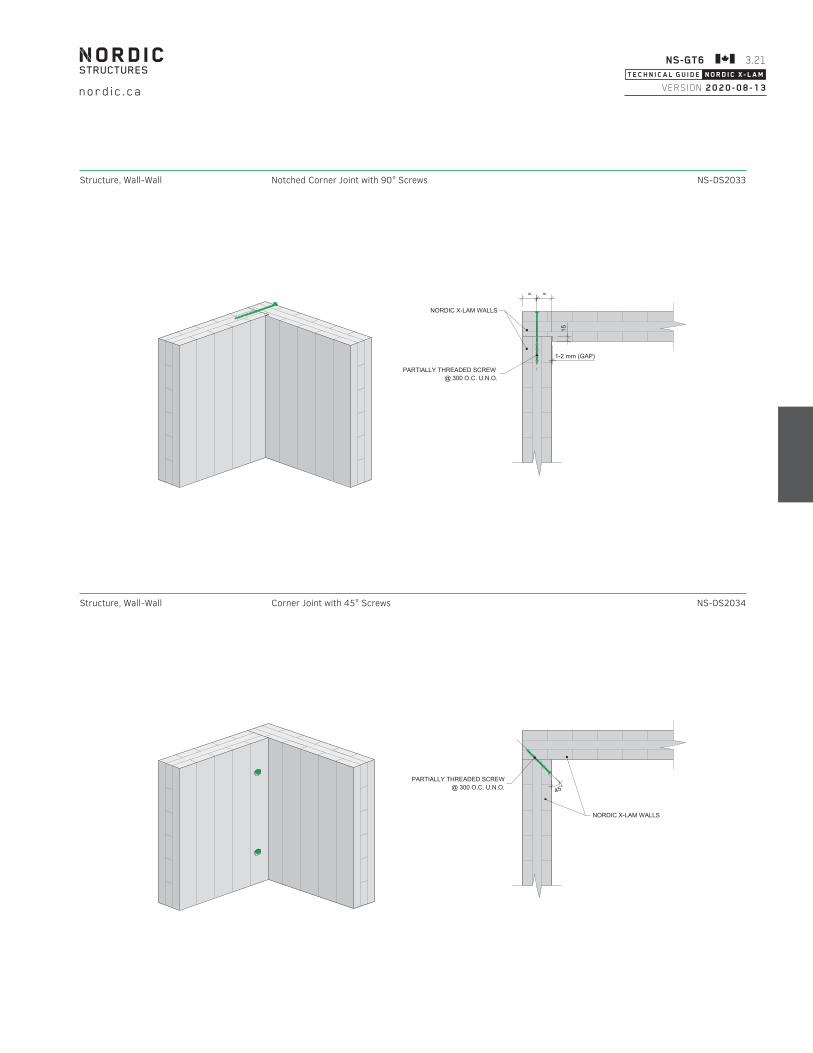
nordic .ca
NS-GT6 3.21T E C H N I C A L G U I D E N O R D I C X- L A M
VERSION 2020-08-13
= =
2020-02-01
1-2 mm (GAP)
TITLE
CATEGORY DATE EGAPELACS
Notched Corner Joint with 90° Screws
-llaW-llaW ,erutcurtS
NS-DS2033-CA-enDRAWING
15
NORDIC X-LAM WALLS
PARTIALLY THREADED SCREW @ 300 O.C. U.N.O.
45°
2020-02-01
TITLE
CATEGORY DATE EGAPELACS
Corner Joint with 45° Screws
-llaW-llaW ,erutcurtS
NS-DS2034-CA-enDRAWING
NORDIC X-LAM WALLS
PARTIALLY THREADED SCREW@ 300 O.C. U.N.O.
Structure, Wall-Wall Notched Corner Joint with 90° Screws NS-DS2033
Structure, Wall-Wall Corner Joint with 45° Screws NS-DS2034

nordic .ca
3.22 NS-GT6 T E C H N I C A L G U I D E N O R D I C X- L A M
VERSION 2020-08-13
= =
2020-02-01
TITLE
CATEGORY DATE EGAPELACS
T-Joint with 90° Screws
-llaW-llaW ,erutcurtS
NS-DS2035-CA-enDRAWING
NORDIC X-LAM WALLS
PARTIALLY THREADED SCREW @ 300 O.C. U.N.O.
45°45°
2020-02-01
TITLE
CATEGORY
T-Joint with 45° Screws
Structure, Wall-WallDATE EGAPELACS
-
NS-DS2036-CA-enDRAWING
NORDIC X-LAM WALLS
PARTIALLY THREADED SCREWS@ 300 O.C. U.N.O., STAGGERED
Structure, Wall-Wall T-Joint with 90° Screws NS-DS2035
Structure, Wall-Wall T-Joint with 45° Screws NS-DS2036

nordic .ca
NS-GT6 3.23T E C H N I C A L G U I D E N O R D I C X- L A M
VERSION 2020-08-13
2020-02-01
TITLE
CATEGORY DATE EGAPELACS
Vertical, Double-Member Beam
gnibmulP dna ,lacirtcelE ,lacinahceM -
DRAWING
NS-DS2501-CA-en
PROVIDE NECESSARY SPACING FOR PLUMBING
METAL STUDS AND INSULATION
NORDIC X-LAMSLAB
OPENING, CUT ON SITE( BY OTHERS)
PIPE
NORDIC LAM BEAM
GYPSUM BOARD
NORDIC LAM COLUMN
2020-02-01
TITLE
CATEGORY DATE EGAPELACS
Horizontal, Pre-Machined Opening
gnibmulP dna ,lacirtcelE ,lacinahceM -
DRAWING
NS-DS2502-CA-en
PRE-MACHINED OPENING
NORDIC X-LAM LINTEL
NORDIC X-LAM WALL
Mechanical, Electrical, and Plumbing Vertical, Double-Member Beam NS-DS2501
Mechanical, Electrical, and Plumbing Horizontal, Pre-Machined Opening NS-DS2502
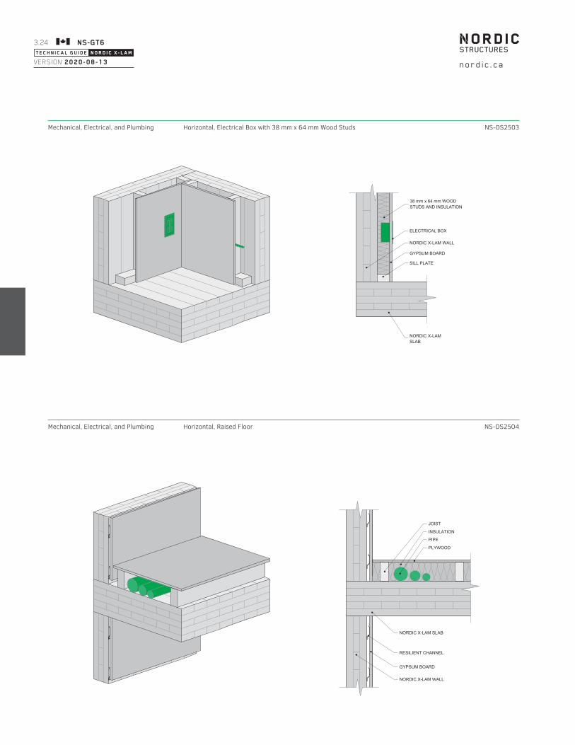
nordic .ca
3.24 NS-GT6 T E C H N I C A L G U I D E N O R D I C X- L A M
VERSION 2020-08-13
2020-02-01
TITLE
CATEGORY DATE EGAPELACS
Horizontal, Electrical Box with 38 mm x 64 mm Wood Studs
gnibmulP dna ,lacirtcelE ,lacinahceM -
DRAWING
NS-DS2503-CA-en
38 mm x 64 mm WOOD STUDS AND INSULATION
ELECTRICAL BOX
NORDIC X-LAM WALL
GYPSUM BOARD
SILL PLATE
NORDIC X-LAM SLAB
2020-02-01
TITLE
CATEGORY DATE EGAPELACS
Horizontal, Raised Floor
gnibmulP dna ,lacirtcelE ,lacinahceM -
DRAWING
NS-DS2504-CA-en
NORDIC X-LAM SLAB
NORDIC X-LAM WALL
GYPSUM BOARD
RESILIENT CHANNEL
PLYWOOD
PIPE
JOIST
INSULATION
Mechanical, Electrical, and Plumbing Horizontal, Electrical Box with 38 mm x 64 mm Wood Studs NS-DS2503
Mechanical, Electrical, and Plumbing Horizontal, Raised Floor NS-DS2504

nordic .ca
NS-GT6 3.25T E C H N I C A L G U I D E N O R D I C X- L A M
VERSION 2020-08-13
2020-02-01
TITLE
CATEGORY DATE EGAPELACS
Horizontal, Suspended Ceiling
gnibmulP dna ,lacirtcelE ,lacinahceM -
DRAWING
NS-DS2505-CA-en
METAL FURRING
METAL STUDS AND INSULATION
GYPSUM BOARDS
NORDIC X-LAMSLAB
MECHANICAL DUCTPIPE OR DUCT
NONCOMBUSTIBLE INSULATION
2020-02-01
TITLE
CATEGORY DATE EGAPELACS
Horizontal, Bevelled Beam
gnibmulP dna ,lacirtcelE ,lacinahceM -
DRAWING
NS-DS2507-CA-en
NORDIC X-LAM SLAB
NORDIC LAM COLUMN
PIPE
NORDIC LAM BEAM
Mechanical, Electrical, and Plumbing Horizontal, Suspended Ceiling NS-DS2505
Mechanical, Electrical, and Plumbing Horizontal, Bevelled Beam NS-DS2507
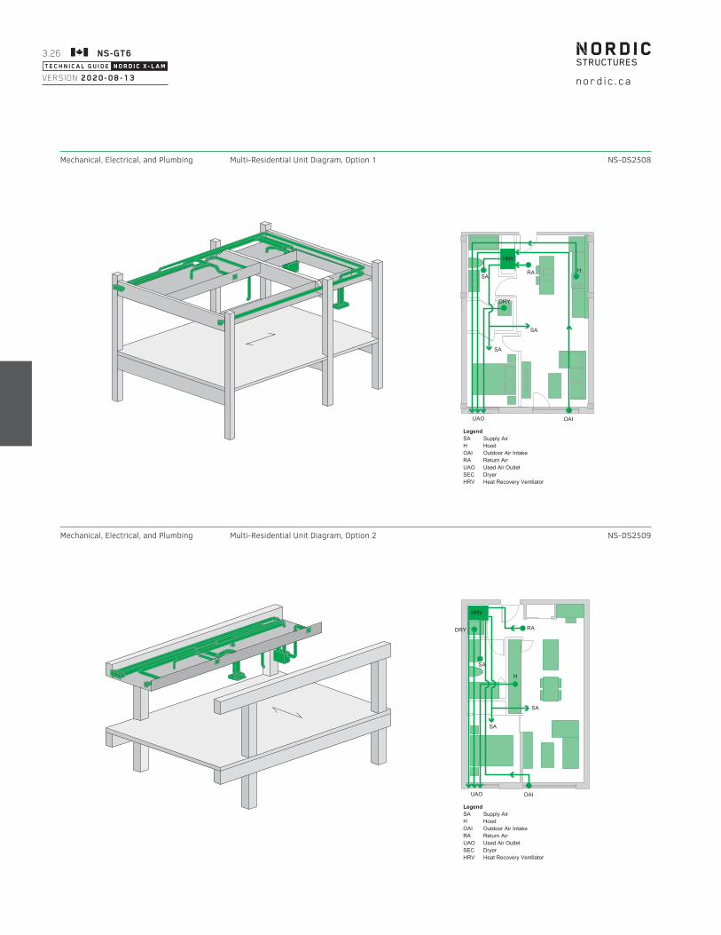
nordic .ca
3.26 NS-GT6 T E C H N I C A L G U I D E N O R D I C X- L A M
VERSION 2020-08-13
2020-02-01
UAO OAI
SAH
HRV
DRY
RA
SA
SA
TITLE
CATEGORY DATE EGAPELACS
Multi-Residential Unit Diagram, Option 1
gnibmulP dna ,lacirtcelE ,lacinahceM -
DRAWING
NS-DS2508-CA-en
LegendSA Supply AirH HoodOAI Outdoor Air IntakeRA Return AirUAO Used Air OutletSEC DryerHRV Heat Recovery Ventilator
2020-02-01
SA
SA
H
RA
HRV
UAO OAI
DRY
SA
DATE EGAPELACS
Multi-Residential Unit Diagram, Option 2
gnibmulP dna ,lacirtcelE ,lacinahceM -
TITLE
CATEGORY
DRAWING
NS-DS2509-CA-en
LegendSA Supply AirH HoodOAI Outdoor Air IntakeRA Return AirUAO Used Air OutletSEC DryerHRV Heat Recovery Ventilator
Mechanical, Electrical, and Plumbing Multi-Residential Unit Diagram, Option 1 NS-DS2508
Mechanical, Electrical, and Plumbing Multi-Residential Unit Diagram, Option 2 NS-DS2509

VERSION2020-08-13
4
T ECHNIC A L GU IDENOR DIC X-L A M
NS-GT6ENGLISH
ARCHITECTURAL DETAILS
nordic .ca
4.2 NS-GT6 T E C H N I C A L G U I D E N O R D I C X- L A M
VERSION 2020-08-13
1.0 General
1.1 This document supersedes all previous versions. For the latest version, consult nordic.ca or contact Nordic Structures.
1.2 The information contained in this document is provided for information purposes only. This information should not be used for any application without examination and verification of its accuracy, suitability and applicability by a licensed engineer, architect or other professional. Nordic Structures does not guarantee that the information is suitable for any general or particular use, and assumes no responsibility for the use, application of and / or reference to the information.
1.3 Certain commercial products are identified in this document in order to properly represent the test procedure. In no case does such identification imply recommendations or endorsement by Nordic Structures, nor does it imply that the product or material identified is the best available for the purpose.
1.4 For more information, consult nordic.ca or contact Nordic Structures.
2.0 Fire Safety
2.1 The fire resistance rating (FRR) is determined using the design methodology specified in Annex B of CSA O86-14, Engineering design in wood. The fire resistance rating may also be determined on the basis of the results of tests conducted in conformance with CAN/ULC-S101, Fire Endurance Tests of Building Construction and Materials.
2.2 To determine the fire resistance of an element or assembly according to other assumptions than those specified in this document, consult the Nordic X-Lam technical guide or use Nordic Sizer software.
2.3 The fire performance criteria for evaluating the separating function of building elements shall be considered when required by the applicable building code.
2.4 For this purpose, among other requirements, many firestop systems suitable for mass timber are available. For more details, consult the product suppliers.
2.5 Additional references: Fire-Resistance-Tested Mass Timber Assemblies and Penetrations.
3.0 Envelope
3.1 Good thermal insulation is never arbitrary and must always be chosen according to location, area and climate.
3.2 The total thermal resistance of an assembly is calculated according to the values of thermal conductivity, λ, and thermal resistance, RSI, indicated in the following table.
3.3 To convert the thermal resistance of the International System (RSI) [m²K/W] to the R-value [ft²Fh/BTU], divide the RSI value by 0.1761.
3.4 As stated in technical note NS-NT602-CA-en, Nordic X-Lam cross-laminated timber acts as a vapor barrier.
3.5 The use of closed cell spray polyurethane is not recommended for exterior wall assemblies made of cross-laminated timber because of its low permeability.
3.6 The study of the building envelope, including the control of condensation, the transfers of heat, air, moisture and sound, as well as the details of joining and fixing of the coverings, shall be carried out in accordance with the applicable building code.
GENERAL NOTES
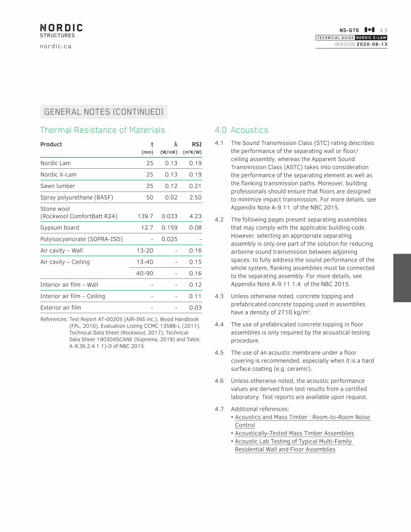
nordic .ca
NS-GT6 4.3T E C H N I C A L G U I D E N O R D I C X- L A M
VERSION 2020-08-13
Thermal Resistance of Materials
Product t λ RSI (mm) (W/mK) (m2K/W)
Nordic Lam 25 0.13 0.19
Nordic X-Lam 25 0.13 0.19
Sawn lumber 25 0.12 0.21
Spray polyurethane (BASF) 50 0.02 2.50
Stone wool (Rockwool ComfortBatt R24) 139.7 0.033 4.23
Gypsum board 12.7 0.159 0.08
Polyisocyanurate (SOPRA-ISO) - 0.025 -
Air cavity – Wall 13-20 - 0.16
Air cavity – Ceiling 13-40 - 0.15
40-90 - 0.16
Interior air film – Wall - - 0.12
Interior air film – Ceiling - - 0.11
Exterior air film - - 0.03
References: Test Report AT-00205 (AIR-INS inc.), Wood Handbook (FPL, 2010), Evaluation Listing CCMC 13588-L (2011), Technical Data Sheet (Rockwool, 2017), Technical Data Sheet 190304SCANE (Soprema, 2019) and Table A-9.36.2.4.1.1)-D of NBC 2015.
GENERAL NOTES (CONTINUED)
4.0 Acoustics4.1 The Sound Transmission Class (STC) rating describes
the performance of the separating wall or floor/ceiling assembly, whereas the Apparent Sound Transmission Class (ASTC) takes into consideration the performance of the separating element as well as the flanking transmission paths. Moreover, building professionals should ensure that floors are designed to minimize impact transmission. For more details, see Appendix Note A-9.11. of the NBC 2015.
4.2 The following pages present separating assemblies that may comply with the applicable building code. However, selecting an appropriate separating assembly is only one part of the solution for reducing airborne sound transmission between adjoining spaces: to fully address the sound performance of the whole system, flanking assemblies must be connected to the separating assembly. For more details, see Appendix Note A-9.11.1.4. of the NBC 2015.
4.3 Unless otherwise noted, concrete topping and prefabricated concrete topping used in assemblies have a density of 2710 kg/m3.
4.4 The use of prefabricated concrete topping in floor assemblies is only required by the acoustical testing procedure.
4.5 The use of an acoustic membrane under a floor covering is recommended, especially when it is a hard surface coating (e.g. ceramic).
4.6 Unless otherwise noted, the acoustic performance values are derived from test results from a certified laboratory. Test reports are available upon request.
4.7 Additional references: • Acoustics and Mass Timber : Room-to-Room Noise
Control• Acoustically-Tested Mass Timber Assemblies• Acoustic Lab Testing of Typical Multi-Family
Residential Wall and Floor Assemblies
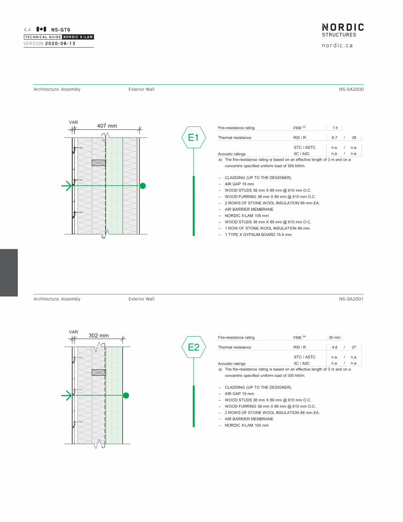
nordic .ca
4.4 NS-GT6 T E C H N I C A L G U I D E N O R D I C X- L A M
VERSION 2020-08-13
E1
2020-02-01
TITLE
CATEGORY DATESCALE
Architecture, Assembly 1:10PAGE
DRAWING
Exterior Wall NS-DA2000-CA-en
407 mmVAR
E2
2020-02-01
TITLE
CATEGORY DATESCALE
Architecture, Assembly 1:10PAGE
DRAWING
Exterior Wall NS-DA2001-CA-en
302 mmVAR
Architecture, Assembly Exterior Wall NS-DA2000
Architecture, Assembly Exterior Wall NS-DA2001
Fire-resistance rating FRR (a) 1 h E1
Thermal resistance RSI / R 6.7 / 38 NS-DA2000-CA-en
n.a. / n.a.Acoustic ratings n.a. / n.a.
STC / ASTCIIC / AIIC
a) The fire-resistance rating is based on an effective length of 3 m and on a concentric specified uniform load of 300 kN/m.
‒ CLADDING (UP TO THE DESIGNER)‒ AIR GAP 19 mm‒ WOOD STUDS 38 mm X 89 mm @ 610 mm O.C.‒ WOOD FURRING 38 mm X 89 mm @ 610 mm O.C.‒ 2 ROWS OF STONE WOOL INSULATION 89 mm EA.‒ AIR BARRIER MEMBRANE‒ NORDIC X-LAM 105 mm‒ WOOD STUDS 38 mm X 89 mm @ 610 mm O.C.‒ 1 ROW OF STONE WOOL INSULATION 89 mm‒ 1 TYPE X GYPSUM BOARD 15.9 mm
Fire-resistance rating FRR (a) 30 min E2
Thermal resistance RSI / R 4.8 / 27 NS-DA2001-CA-en
n.a. / n.a.Acoustic ratings n.a. / n.a.
STC / ASTCIIC / AIIC
a) The fire-resistance rating is based on an effective length of 3 m and on a concentric specified uniform load of 300 kN/m.
‒ CLADDING (UP TO THE DESIGNER)‒ AIR GAP 19 mm‒ WOOD STUDS 38 mm X 89 mm @ 610 mm O.C.‒ WOOD FURRING 38 mm X 89 mm @ 610 mm O.C.‒ 2 ROWS OF STONE WOOL INSULATION 89 mm EA.‒ AIR BARRIER MEMBRANE‒ NORDIC X-LAM 105 mm
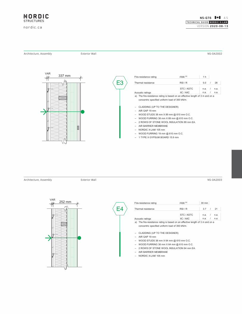
nordic .ca
NS-GT6 4.5T E C H N I C A L G U I D E N O R D I C X- L A M
VERSION 2020-08-13
E3
2020-02-01
TITLE
CATEGORY DATESCALE
Architecture, Assembly 1:10PAGE
DRAWING
Exterior Wall NS-DA2002-CA-en
337 mmVAR
E4
2020-02-01
TITLE
CATEGORY DATESCALE
Architecture, Assembly 1:10PAGE
DRAWING
Exterior Wall NS-DA2003-CA-en
252 mmVAR
Architecture, Assembly Exterior Wall NS-DA2002
Architecture, Assembly Exterior Wall NS-DA2003
Fire-resistance rating FRR (a) 1 h E3
Thermal resistance RSI / R 5.0 / 28 NS-DA2002-CA-en
n.a. / n.a.Acoustic ratings n.a. / n.a.
STC / ASTCIIC / AIIC
a) The fire-resistance rating is based on an effective length of 3 m and on a concentric specified uniform load of 300 kN/m.
‒ CLADDING (UP TO THE DESIGNER)‒ AIR GAP 19 mm‒ WOOD STUDS 38 mm X 89 mm @ 610 mm O.C.‒ WOOD FURRING 38 mm X 89 mm @ 610 mm O.C.‒ 2 ROWS OF STONE WOOL INSULATION 89 mm EA.‒ AIR BARRIER MEMBRANE‒ NORDIC X-LAM 105 mm‒ WOOD FURRING 19 mm @ 610 mm O.C.‒ 1 TYPE X GYPSUM BOARD 15.9 mm
Fire-resistance rating FRR (a) 30 min E4
Thermal resistance RSI / R 3.7 / 21 NS-DA2003-CA-en
n.a. / n.a.Acoustic ratings n.a. / n.a.
‒ CLADDING (UP TO THE DESIGNER)‒ AIR GAP 19 mm‒ WOOD STUDS 38 mm X 64 mm @ 610 mm O.C.‒ WOOD FURRING 38 mm X 64 mm @ 610 mm O.C.‒ 2 ROWS OF STONE WOOL INSULATION 64 mm EA.‒ AIR BARRIER MEMBRANE‒ NORDIC X-LAM 105 mm
STC / ASTCIIC / AIIC
a) The fire-resistance rating is based on an effective length of 3 m and on a concentric specified uniform load of 300 kN/m.
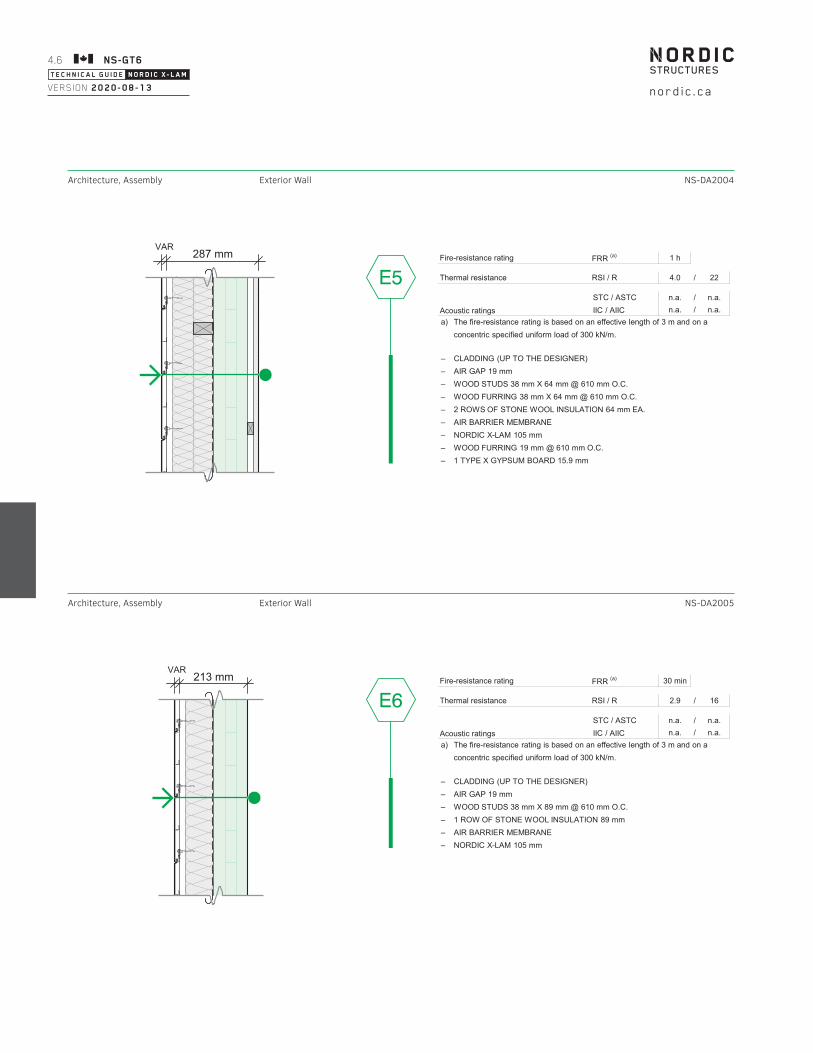
nordic .ca
4.6 NS-GT6 T E C H N I C A L G U I D E N O R D I C X- L A M
VERSION 2020-08-13
E5
2020-02-01
TITLE
CATEGORY DATESCALE
Architecture, Assembly 1:10PAGE
DRAWING
Exterior Wall NS-DA2004-CA-en
287 mmVAR
E6
2020-02-01
TITLE
CATEGORY DATESCALE
Architecture, Assembly 1:10PAGE
DRAWING
Exterior Wall NS-DA2005-CA-en
213 mmVAR
Architecture, Assembly Exterior Wall NS-DA2004
Architecture, Assembly Exterior Wall NS-DA2005
Fire-resistance rating FRR (a) 1 h E5
Thermal resistance RSI / R 4.0 / 22 NS-DA2004-CA-en
n.a. / n.a.Acoustic ratings n.a. / n.a.
‒ CLADDING (UP TO THE DESIGNER)‒ AIR GAP 19 mm‒ WOOD STUDS 38 mm X 64 mm @ 610 mm O.C.‒ WOOD FURRING 38 mm X 64 mm @ 610 mm O.C.‒ 2 ROWS OF STONE WOOL INSULATION 64 mm EA.‒ AIR BARRIER MEMBRANE‒ NORDIC X-LAM 105 mm‒ WOOD FURRING 19 mm @ 610 mm O.C.‒ 1 TYPE X GYPSUM BOARD 15.9 mm
STC / ASTCIIC / AIIC
a) The fire-resistance rating is based on an effective length of 3 m and on a concentric specified uniform load of 300 kN/m.
Fire-resistance rating FRR (a) 30 min E6
Thermal resistance RSI / R 2.9 / 16 NS-DA2005-CA-en
n.a. / n.a.Acoustic ratings n.a. / n.a.
‒ CLADDING (UP TO THE DESIGNER)‒ AIR GAP 19 mm‒ WOOD STUDS 38 mm X 89 mm @ 610 mm O.C.‒ 1 ROW OF STONE WOOL INSULATION 89 mm‒ AIR BARRIER MEMBRANE‒ NORDIC X-LAM 105 mm
STC / ASTCIIC / AIIC
a) The fire-resistance rating is based on an effective length of 3 m and on a concentric specified uniform load of 300 kN/m.
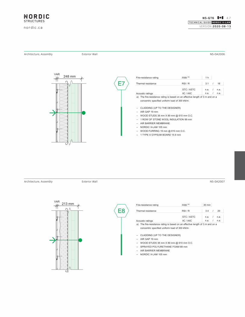
nordic .ca
NS-GT6 4.7T E C H N I C A L G U I D E N O R D I C X- L A M
VERSION 2020-08-13
E7
2020-02-01
TITLE
CATEGORY DATESCALE
Architecture, Assembly 1:10PAGE
DRAWING
Exterior Wall NS-DA2006-CA-en
248 mmVAR
E8
2020-02-01
TITLE
CATEGORY DATESCALE
Architecture, Assembly 1:10PAGE
DRAWING
Exterior Wall NS-DA2007-CA-en
213 mmVAR
Architecture, Assembly Exterior Wall NS-DA2006
Architecture, Assembly Exterior Wall NS-DA2007
Fire-resistance rating FRR (a) 1 h E7
Thermal resistance RSI / R 3.1 / 18 NS-DA2006-CA-en
n.a. / n.a.Acoustic ratings n.a. / n.a.
‒ CLADDING (UP TO THE DESIGNER)‒ AIR GAP 19 mm‒ WOOD STUDS 38 mm X 89 mm @ 610 mm O.C.‒ 1 ROW OF STONE WOOL INSULATION 89 mm‒ AIR BARRIER MEMBRANE‒ NORDIC X-LAM 105 mm‒ WOOD FURRING 19 mm @ 610 mm O.C.‒ 1 TYPE X GYPSUM BOARD 15.9 mm
STC / ASTCIIC / AIIC
a) The fire-resistance rating is based on an effective length of 3 m and on a concentric specified uniform load of 300 kN/m.
Fire-resistance rating FRR (a) 30 min E8
Thermal resistance RSI / R 3.4 / 20 NS-DA2007-CA-en
n.a. / n.a.Acoustic ratings n.a. / n.a.
‒ CLADDING (UP TO THE DESIGNER)‒ AIR GAP 19 mm‒ WOOD STUDS 38 mm X 89 mm @ 610 mm O.C.‒ SPRAYED POLYURETHANE FOAM 89 mm‒ AIR BARRIER MEMBRANE‒ NORDIC X-LAM 105 mm
STC / ASTCIIC / AIIC
a) The fire-resistance rating is based on an effective length of 3 m and on a concentric specified uniform load of 300 kN/m.
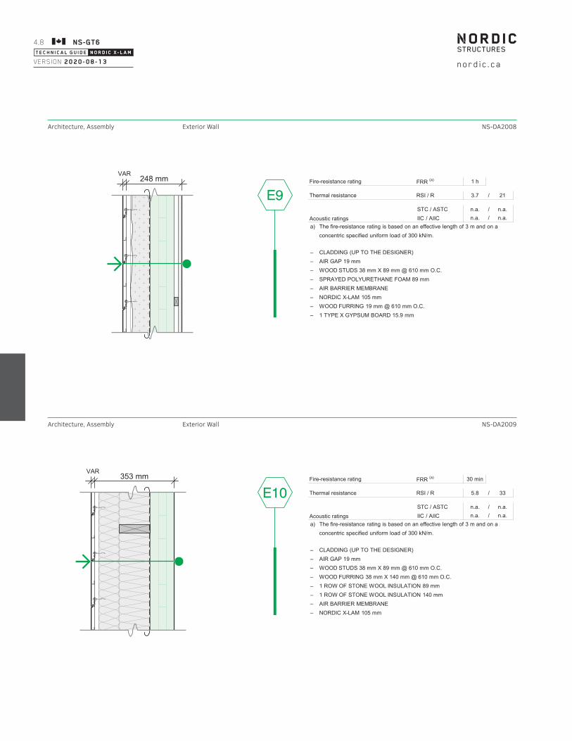
nordic .ca
4.8 NS-GT6 T E C H N I C A L G U I D E N O R D I C X- L A M
VERSION 2020-08-13
E9
2020-02-01
TITLE
CATEGORY DATESCALE
Architecture, Assembly 1:10PAGE
DRAWING
Exterior Wall NS-DA2008-CA-en
248 mmVAR
E10
2020-02-01
TITLE
CATEGORY DATESCALE
Architecture, Assembly 1:10PAGE
DRAWING
Exterior Wall NS-DA2009-CA-en
353 mmVAR
Architecture, Assembly Exterior Wall NS-DA2008
Architecture, Assembly Exterior Wall NS-DA2009
Fire-resistance rating FRR (a) 1 h E9
Thermal resistance RSI / R 3.7 / 21 NS-DA2008-CA-en
n.a. / n.a.Acoustic ratings n.a. / n.a.
‒ CLADDING (UP TO THE DESIGNER)‒ AIR GAP 19 mm‒ WOOD STUDS 38 mm X 89 mm @ 610 mm O.C.‒ SPRAYED POLYURETHANE FOAM 89 mm‒ AIR BARRIER MEMBRANE‒ NORDIC X-LAM 105 mm‒ WOOD FURRING 19 mm @ 610 mm O.C.‒ 1 TYPE X GYPSUM BOARD 15.9 mm
STC / ASTCIIC / AIIC
a) The fire-resistance rating is based on an effective length of 3 m and on a concentric specified uniform load of 300 kN/m.
Fire-resistance rating FRR (a) 30 min E10
Thermal resistance RSI / R 5.8 / 33 NS-DA2009-CA-en
n.a. / n.a.Acoustic ratings n.a. / n.a.
‒ CLADDING (UP TO THE DESIGNER)‒ AIR GAP 19 mm‒ WOOD STUDS 38 mm X 89 mm @ 610 mm O.C.‒ WOOD FURRING 38 mm X 140 mm @ 610 mm O.C.‒ 1 ROW OF STONE WOOL INSULATION 89 mm‒ 1 ROW OF STONE WOOL INSULATION 140 mm‒ AIR BARRIER MEMBRANE‒ NORDIC X-LAM 105 mm
STC / ASTCIIC / AIIC
a) The fire-resistance rating is based on an effective length of 3 m and on a concentric specified uniform load of 300 kN/m.

nordic .ca
NS-GT6 4.9T E C H N I C A L G U I D E N O R D I C X- L A M
VERSION 2020-08-13
E11
2020-02-01
TITLE
CATEGORY DATESCALE
Architecture, Assembly 1:10PAGE
DRAWING
Exterior Wall NS-DA2010-CA-en
388 mmVAR
2020-02-01
P1
TITLE
CATEGORY DATESCALE
Architecture, Assembly 1:10PAGE
DRAWING
Partition NS-DA2100-CA-en
105 mm
Architecture, Assembly Exterior Wall NS-DA2010
Architecture, Assembly Partition NS-DA2100
Fire-resistance rating FRR (a) 1 h E11
Thermal resistance RSI / R 6.1 / 35 NS-DA2010-CA-en
n.a. / n.a.Acoustic ratings n.a. / n.a.
‒ CLADDING (UP TO THE DESIGNER)‒ AIR GAP 19 mm‒ WOOD STUDS 38 mm X 89 mm @ 610 mm O.C.‒ WOOD FURRING 38 mm X 140 mm @ 610 mm O.C.‒ 1 ROW OF STONE WOOL INSULATION 89 mm‒ 1 ROW OF STONE WOOL INSULATION 140 mm‒ AIR BARRIER MEMBRANE‒ NORDIC X-LAM 105 mm‒ WOOD FURRING 19 mm @ 610 mm O.C.‒ 1 TYPE X GYPSUM BOARD 15.9 mm
STC / ASTCIIC / AIIC
a) The fire-resistance rating is based on an effective length of 3 m and on a concentric specified uniform load of 300 kN/m.
Fire-resistance rating FRR (a) 30 min / 30 min P1
Thermal resistance RSI / R n.a. / n.a. NS-DA2100-CA-en
33 / n.a.Acoustic ratings n.a. / n.a.
‒ NORDIC X-LAM 105 mm
a) The fire-resistance ratings on each side of the partition are based on an effective length of 3 m and on a concentric specified uniform load of 300 kN/m.
b) Composition and acoustic performance taken from the CLT Handbook –Canadian Edition (FPInnovations, 2011). Acoustic performance based on a CLT thickness of 95-115 mm.
STC (b) / ASTCIIC / AIIC
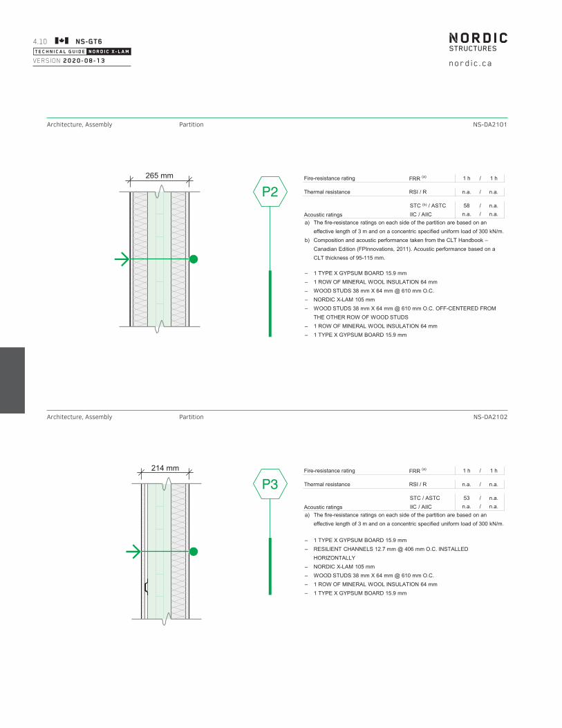
nordic .ca
4.10 NS-GT6 T E C H N I C A L G U I D E N O R D I C X- L A M
VERSION 2020-08-13
2020-02-01
P2
TITLE
CATEGORY DATESCALE
Architecture, Assembly 1:10PAGE
DRAWING
Partition NS-DA2101-CA-en
265 mm
2020-02-01
P3
TITLE
CATEGORY DATESCALE
Architecture, Assembly 1:10PAGE
DRAWING
Partition NS-DA2102-CA-en
214 mm
Architecture, Assembly Partition NS-DA2101
Architecture, Assembly Partition NS-DA2102
Fire-resistance rating FRR (a) 1 h / 1 h P2
Thermal resistance RSI / R n.a. / n.a. NS-DA2101-CA-en
58 / n.a.Acoustic ratings n.a. / n.a.
‒ 1 TYPE X GYPSUM BOARD 15.9 mm‒ 1 ROW OF MINERAL WOOL INSULATION 64 mm‒ WOOD STUDS 38 mm X 64 mm @ 610 mm O.C.‒ NORDIC X-LAM 105 mm‒ WOOD STUDS 38 mm X 64 mm @ 610 mm O.C. OFF-CENTERED FROM
THE OTHER ROW OF WOOD STUDS‒ 1 ROW OF MINERAL WOOL INSULATION 64 mm‒ 1 TYPE X GYPSUM BOARD 15.9 mm
a) The fire-resistance ratings on each side of the partition are based on an effective length of 3 m and on a concentric specified uniform load of 300 kN/m.
b) Composition and acoustic performance taken from the CLT Handbook –Canadian Edition (FPInnovations, 2011). Acoustic performance based on a CLT thickness of 95-115 mm.
STC (b) / ASTCIIC / AIIC
Fire-resistance rating FRR (a) 1 h / 1 h P3
Thermal resistance RSI / R n.a. / n.a. NS-DA2102-CA-en
53 / n.a.Acoustic ratings n.a. / n.a.
‒ 1 TYPE X GYPSUM BOARD 15.9 mm‒ RESILIENT CHANNELS 12.7 mm @ 406 mm O.C. INSTALLED
HORIZONTALLY‒ NORDIC X-LAM 105 mm‒ WOOD STUDS 38 mm X 64 mm @ 610 mm O.C.‒ 1 ROW OF MINERAL WOOL INSULATION 64 mm‒ 1 TYPE X GYPSUM BOARD 15.9 mm
STC / ASTCIIC / AIIC
a) The fire-resistance ratings on each side of the partition are based on an effective length of 3 m and on a concentric specified uniform load of 300 kN/m.

nordic .ca
NS-GT6 4.11T E C H N I C A L G U I D E N O R D I C X- L A M
VERSION 2020-08-13
2020-02-01
TITLE
CATEGORY DATESCALE
Architecture, Assembly 1:10PAGE
DRAWING
Partition NS-DA2103-CA-en
163 mm
P4
2020-02-01
TITLE
CATEGORY DATESCALE
Architecture, Assembly 1:10PAGE
DRAWING
Partition NS-DA2104-CA-en
134 mm
P5
Architecture, Assembly Partition NS-DA2103
Architecture, Assembly Partition NS-DA2104
Fire-resistance rating FRR (a) 1 h / 1 h P4
Thermal resistance RSI / R n.a. / n.a. NS-DA2103-CA-en
37 / n.a.Acoustic ratings n.a. / n.a.
‒ 1 TYPE X GYPSUM BOARD 15.9 mm‒ RESILIENT CHANNELS 12.7 mm @ 406 mm O.C. INSTALLED
HORIZONTALLY‒ NORDIC X-LAM 105 mm‒ RESILIENT CHANNELS 12.7 mm @ 406 mm O.C. INSTALLED
HORIZONTALLY‒ 1 TYPE X GYPSUM BOARD 15.9 mm
a) The fire-resistance ratings on each side of the partition are based on an effective length of 3 m and on a concentric specified uniform load of 300 kN/m.
b) Composition and acoustic performance taken from the CLT Handbook –Canadian Edition (FPInnovations, 2011). Acoustic performance based on a CLT thickness of 95-115 mm.
STC (b) / ASTCIIC / AIIC
Fire-resistance rating FRR (a) 30 min / 1 h P5
Thermal resistance RSI / R n.a. / n.a. NS-DA2104-CA-en
37 / n.a.Acoustic ratings n.a. / n.a.
‒ NORDIC X-LAM 105 mm‒ RESILIENT CHANNELS 12.7 mm @ 406 mm O.C. INSTALLED
HORIZONTALLY‒ 1 TYPE X GYPSUM BOARD 15.9 mm
a) The fire-resistance ratings on each side of the partition are based on an effective length of 3 m and on a concentric specified uniform load of 300 kN/m.
b) Composition and acoustic performance taken from the CLT Handbook –Canadian Edition (FPInnovations, 2011). Acoustic performance based on a CLT thickness of 95-115 mm.
STC (b) / ASTCIIC / AIIC
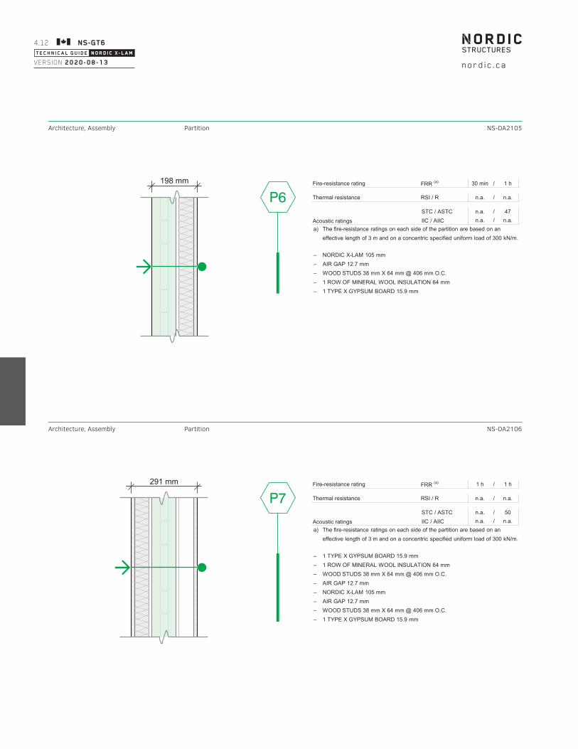
nordic .ca
4.12 NS-GT6 T E C H N I C A L G U I D E N O R D I C X- L A M
VERSION 2020-08-13
2020-02-01
TITLE
CATEGORY DATESCALE
Architecture, Assembly 1:10PAGE
DRAWING
Partition NS-DA2105-CA-en
198 mm
P6
2020-02-01
TITLE
CATEGORY DATESCALE
Architecture, Assembly 1:10PAGE
DRAWING
Partition NS-DA2106-CA-en
291 mm
P7
Architecture, Assembly Partition NS-DA2105
Architecture, Assembly Partition NS-DA2106
Fire-resistance rating FRR (a) 30 min / 1 h P6
Thermal resistance RSI / R n.a. / n.a. NS-DA2105-CA-en
n.a. / 47Acoustic ratings n.a. / n.a.
‒ NORDIC X-LAM 105 mm‒ AIR GAP 12.7 mm‒ WOOD STUDS 38 mm X 64 mm @ 406 mm O.C.‒ 1 ROW OF MINERAL WOOL INSULATION 64 mm‒ 1 TYPE X GYPSUM BOARD 15.9 mm
STC / ASTCIIC / AIIC
a) The fire-resistance ratings on each side of the partition are based on an effective length of 3 m and on a concentric specified uniform load of 300 kN/m.
Fire-resistance rating FRR (a) 1 h / 1 h P7
Thermal resistance RSI / R n.a. / n.a. NS-DA2106-CA-en
n.a. / 50Acoustic ratings n.a. / n.a.
‒ 1 TYPE X GYPSUM BOARD 15.9 mm‒ 1 ROW OF MINERAL WOOL INSULATION 64 mm‒ WOOD STUDS 38 mm X 64 mm @ 406 mm O.C.‒ AIR GAP 12.7 mm‒ NORDIC X-LAM 105 mm‒ AIR GAP 12.7 mm‒ WOOD STUDS 38 mm X 64 mm @ 406 mm O.C.‒ 1 TYPE X GYPSUM BOARD 15.9 mm
STC / ASTCIIC / AIIC
a) The fire-resistance ratings on each side of the partition are based on an effective length of 3 m and on a concentric specified uniform load of 300 kN/m.
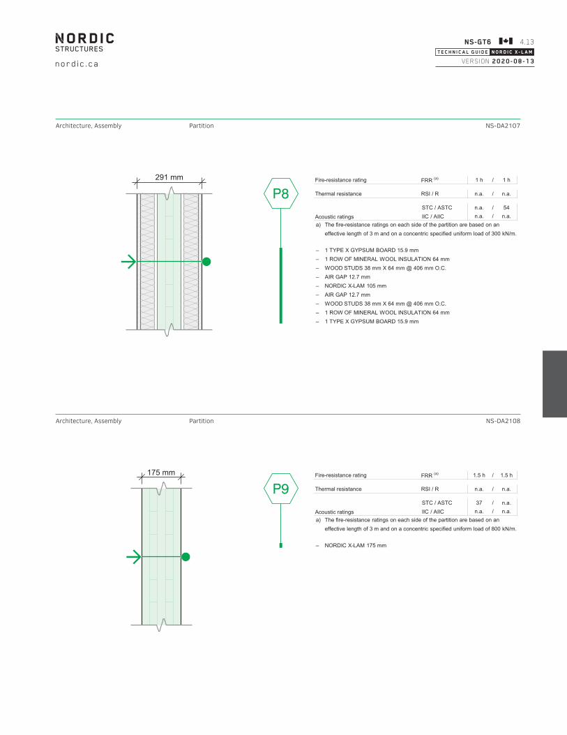
nordic .ca
NS-GT6 4.13T E C H N I C A L G U I D E N O R D I C X- L A M
VERSION 2020-08-13
2020-02-01
TITLE
CATEGORY DATESCALE
Architecture, Assembly 1:10PAGE
DRAWING
Partition NS-DA2107-CA-en
291 mm
P8
2020-02-01
TITLE
CATEGORY DATESCALE
Architecture, Assembly 1:10PAGE
DRAWING
Partition NS-DA2108-CA-en
175 mm
P9
Architecture, Assembly Partition NS-DA2107
Architecture, Assembly Partition NS-DA2108
Fire-resistance rating FRR (a) 1 h / 1 h P8
Thermal resistance RSI / R n.a. / n.a. NS-DA2107-CA-en
n.a. / 54Acoustic ratings n.a. / n.a.
‒ 1 TYPE X GYPSUM BOARD 15.9 mm‒ 1 ROW OF MINERAL WOOL INSULATION 64 mm‒ WOOD STUDS 38 mm X 64 mm @ 406 mm O.C.‒ AIR GAP 12.7 mm‒ NORDIC X-LAM 105 mm‒ AIR GAP 12.7 mm‒ WOOD STUDS 38 mm X 64 mm @ 406 mm O.C.‒ 1 ROW OF MINERAL WOOL INSULATION 64 mm‒ 1 TYPE X GYPSUM BOARD 15.9 mm
STC / ASTCIIC / AIIC
a) The fire-resistance ratings on each side of the partition are based on an effective length of 3 m and on a concentric specified uniform load of 300 kN/m.
Fire-resistance rating FRR (a) 1.5 h / 1.5 h P9
Thermal resistance RSI / R n.a. / n.a. NS-DA2108-CA-en
37 / n.a.Acoustic ratings n.a. / n.a.
‒ NORDIC X-LAM 175 mm
STC / ASTCIIC / AIIC
a) The fire-resistance ratings on each side of the partition are based on an effective length of 3 m and on a concentric specified uniform load of 800 kN/m.

nordic .ca
4.14 NS-GT6 T E C H N I C A L G U I D E N O R D I C X- L A M
VERSION 2020-08-13
2020-02-01
TITLE
CATEGORY DATESCALE
Architecture, Assembly 1:10PAGE
DRAWING
Partition NS-DA2109-CA-en
242 mm
P10
2020-02-01
TITLE
CATEGORY DATESCALE
Architecture, Assembly 1:10PAGE
DRAWING
Partition NS-DA2110-CA-en
385 mm
P11
Architecture, Assembly Partition NS-DA2109
Architecture, Assembly Partition NS-DA2110
Fire-resistance rating FRR (a) 1.5 h / 2.5 h P10
Thermal resistance RSI / R n.a. / n.a. NS-DA2109-CA-en
53 / n.a.Acoustic ratings n.a. / n.a.
‒ NORDIC X-LAM 175 mm‒ Z-CHANNELS (26 GAUGE) 35 mm @ 406 mm O.C.
INSTALLED VERTICALLY‒ 1 ROW OF FIBREGLASS INSULATION OF TYPE
“ROSE FIBERGLAS ECOTOUCH” 38 mm‒ 2 TYPE X GYPSUM BOARDS 15.9 mm EA.
STC / ASTCIIC / AIIC
a) The fire-resistance ratings on each side of the partition are based on an effective length of 3 m and on a concentric specified uniform load of 800 kN/m.
Fire-resistance rating FRR (a) 2.5 h / 2.5 h P11
Thermal resistance RSI / R n.a. / n.a. NS-DA2110-CA-en
71 / n.a.Acoustic ratings n.a. / n.a.
‒ 2 TYPE X GYPSUM BOARDS 15.9 mm EA.‒ METAL STUDS (26 GAUGE) 31 mm X 92 mm @ 406 mm O.C.‒ 1 ROW OF FIBREGLASS INSULATION OF TYPE
“ROSE FIBERGLAS ECOTOUCH” 92 mm‒ AIR GAP 19 mm‒ NORDIC X-LAM 175 mm‒ Z-CHANNELS (26 GAUGE) 35 mm @ 406 mm O.C.
INSTALLED VERTICALLY‒ 1 ROW OF FIBREGLASS INSULATION OF TYPE
“ROSE FIBERGLAS ECOTOUCH” 38 mm ‒ 2 TYPE X GYPSUM BOARDS 15.9 mm EA.
STC / ASTCIIC / AIIC
a) The fire-resistance ratings on each side of the partition are based on an effective length of 3 m and on a concentric specified uniform load of 800 kN/m.

nordic .ca
NS-GT6 4.15T E C H N I C A L G U I D E N O R D I C X- L A M
VERSION 2020-08-13
2020-02-01
TITLE
CATEGORY DATESCALE
Architecture, Assembly 1:10PAGE
DRAWING
Partition NS-DA2111-CA-en
300 mm
P12
2020-02-01
TITLE
CATEGORY DATESCALE
Architecture, Assembly 1:10PAGE
DRAWING
Partition NS-DA2112-CA-en
274 mm
P13
Architecture, Assembly Partition NS-DA2111
Architecture, Assembly Partition NS-DA2112
Fire-resistance rating FRR (a) 2.5 h / 2.5 h P12
Thermal resistance RSI / R n.a. / n.a. NS-DA2111-CA-en
53 / n.a.Acoustic ratings n.a. / n.a.
‒ 2 TYPE X GYPSUM BOARDS 15.9 mm EA.‒ RESILIENT CHANNELS 12.7 mm @ 406 mm O.C.
INSTALLED HORIZONTALLY‒ PLYWOOD STRIPS 12.7 mm @ 406 mm O.C.‒ NORDIC X-LAM 175 mm ‒ Z-CHANNELS (26 GAUGE) 35 mm @ 406 mm O.C.
INSTALLED VERTICALLY‒ 1 ROW OF FIBREGLASS INSULATION OF TYPE
“ROSE FIBERGLAS ECOTOUCH” 38 mm‒ 2 TYPE X GYPSUM BOARDS 15.9 mm EA.
STC / ASTCIIC / AIIC
a) The fire-resistance ratings on each side of the partition are based on an effective length of 3 m and on a concentric specified uniform load of 800 kN/m.
Fire-resistance rating FRR (a) 2.5 h / 2.5 h P13
Thermal resistance RSI / R n.a. / n.a. NS-DA2112-CA-en
53 / n.a.Acoustic ratings n.a. / n.a.
‒ 2 TYPE X GYPSUM BOARDS 15.9 mm EA.‒ NORDIC X-LAM 175 mm‒ Z-CHANNELS (26 GAUGE) 35 mm @ 406 mm O.C.
INSTALLED VERTICALLY‒ 1 ROW OF FIBREGLASS INSULATION OF TYPE
“ROSE FIBERGLAS ECOTOUCH” 38 mm‒ 2 TYPE X GYPSUM BOARDS 15.9 mm EA.
STC / ASTCIIC / AIIC
a) The fire-resistance ratings on each side of the partition are based on an effective length of 3 m and on a concentric specified uniform load of 800 kN/m.
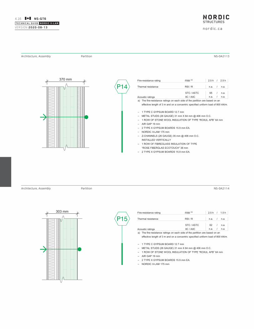
nordic .ca
4.16 NS-GT6 T E C H N I C A L G U I D E N O R D I C X- L A M
VERSION 2020-08-13
2020-02-01
TITLE
CATEGORY DATESCALE
Architecture, Assembly 1:10PAGE
DRAWING
Partition NS-DA2113-CA-en
370 mm
P14
2020-02-01
TITLE
CATEGORY DATESCALE
Architecture, Assembly 1:10PAGE
DRAWING
Partition NS-DA2114-CA-en
303 mm
P15
Architecture, Assembly Partition NS-DA2113
Architecture, Assembly Partition NS-DA2114
Fire-resistance rating FRR (a) 2.5 h / 2.5 h P14
Thermal resistance RSI / R n.a. / n.a. NS-DA2113-CA-en
65 / n.a.Acoustic ratings n.a. / n.a.
‒ 1 TYPE C GYPSUM BOARD 12.7 mm‒ METAL STUDS (26 GAUGE) 31 mm X 64 mm @ 406 mm O.C.‒ 1 ROW OF STONE WOOL INSULATION OF TYPE “ROXUL AFB” 64 mm‒ AIR GAP 19 mm‒ 2 TYPE X GYPSUM BOARDS 15.9 mm EA.‒ NORDIC X-LAM 175 mm‒ Z-CHANNELS (26 GAUGE) 35 mm @ 406 mm O.C.
INSTALLED VERTICALLY ‒ 1 ROW OF FIBREGLASS INSULATION OF TYPE
“ROSE FIBERGLAS ECOTOUCH” 38 mm‒ 2 TYPE X GYPSUM BOARDS 15.9 mm EA.
STC / ASTCIIC / AIIC
a) The fire-resistance ratings on each side of the partition are based on an effective length of 3 m and on a concentric specified uniform load of 800 kN/m.
Fire-resistance rating FRR (a) 2.5 h / 1.5 h P15
Thermal resistance RSI / R n.a. / n.a. NS-DA2114-CA-en
62 / n.a.Acoustic ratings n.a. / n.a.
‒ 1 TYPE C GYPSUM BOARD 12.7 mm‒ METAL STUDS (26 GAUGE) 31 mm X 64 mm @ 406 mm O.C.‒ 1 ROW OF STONE WOOL INSULATION OF TYPE “ROXUL AFB” 64 mm‒ AIR GAP 19 mm‒ 2 TYPE X GYPSUM BOARDS 15.9 mm EA.‒ NORDIC X-LAM 175 mm
STC / ASTCIIC / AIIC
a) The fire-resistance ratings on each side of the partition are based on an effective length of 3 m and on a concentric specified uniform load of 800 kN/m.
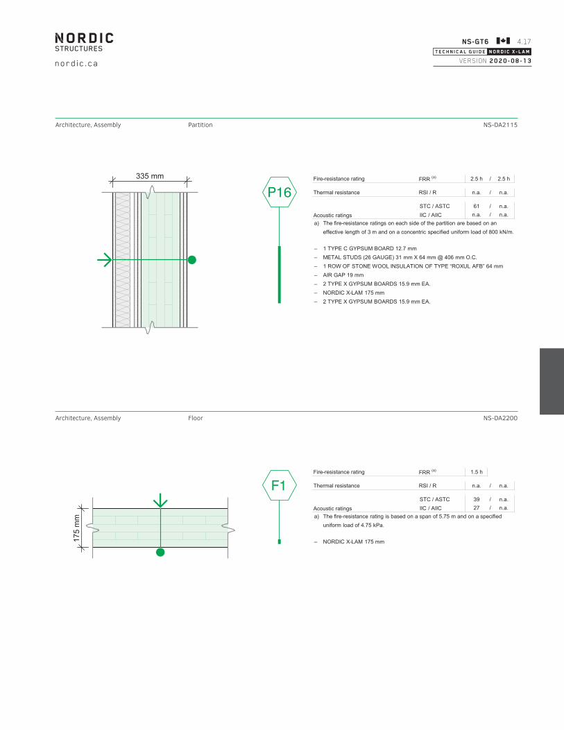
nordic .ca
NS-GT6 4.17T E C H N I C A L G U I D E N O R D I C X- L A M
VERSION 2020-08-13
2020-02-01
TITLE
CATEGORY DATESCALE
Architecture, Assembly 1:10PAGE
DRAWING
Partition NS-DA2115-CA-en
335 mm
P16
2020-02-01
TITLE
CATEGORY DATESCALE
Architecture, Assembly 1:10PAGE
DRAWING
Floor NS-DA2200-CA-en
175
mm
F1
Architecture, Assembly Partition NS-DA2115
Architecture, Assembly Floor NS-DA2200
Fire-resistance rating FRR (a) 2.5 h / 2.5 h P16
Thermal resistance RSI / R n.a. / n.a. NS-DA2115-CA-en
61 / n.a.Acoustic ratings n.a. / n.a.
‒ 1 TYPE C GYPSUM BOARD 12.7 mm‒ METAL STUDS (26 GAUGE) 31 mm X 64 mm @ 406 mm O.C.‒ 1 ROW OF STONE WOOL INSULATION OF TYPE “ROXUL AFB” 64 mm‒ AIR GAP 19 mm‒ 2 TYPE X GYPSUM BOARDS 15.9 mm EA.‒ NORDIC X-LAM 175 mm‒ 2 TYPE X GYPSUM BOARDS 15.9 mm EA.
STC / ASTCIIC / AIIC
a) The fire-resistance ratings on each side of the partition are based on an effective length of 3 m and on a concentric specified uniform load of 800 kN/m.
Fire-resistance rating FRR (a) 1.5 h F1
Thermal resistance RSI / R n.a. / n.a. NS-DA2200-CA-en
39 / n.a.Acoustic ratings 27 / n.a.
‒ NORDIC X-LAM 175 mm
STC / ASTCIIC / AIIC
a) The fire-resistance rating is based on a span of 5.75 m and on a specified uniform load of 4.75 kPa.

nordic .ca
4.18 NS-GT6 T E C H N I C A L G U I D E N O R D I C X- L A M
VERSION 2020-08-13
2020-02-01
FloorTITLE
CATEGORY DATESCALE
Architecture, Assembly 1:10PAGE
DRAWING
NS-DA2201-CA-en
F2
2020-02-01DATE
TITLE
CATEGORY SCALE
Architecture, Assembly 1:10PAGE
DRAWING
Floor NS-DA2202-CA-en
421
mm
F3
Architecture, Assembly Floor NS-DA2201
Architecture, Assembly Floor NS-DA2202
Fire-resistance rating FRR (a) 2.5 h F2
Thermal resistance RSI / R n.a. / n.a. NS-DA2201-CA-en
64 / n.a.Acoustic ratings 59 / n.a.
‒ NORDIC X-LAM 175 mm‒ SUSPENDED CEILING:
‒ RESILIENT METALLIC HANGERS 100 mm‒ METAL TRACKS @ 406 mm O.C. MIN‒ SOUNDPROOFING MATERIAL 100 mm
‒ 2 TYPE X GYPSUM BOARDS 12.7 mm EA.
a) The fire-resistance rating is based on a span of 5.75 m and on a specified uniform load of 4.75 kPa.
b) Composition and acoustic performance taken from the CLT Handbook –Canadian Edition (FPInnovations, 2011). Acoustic performance based on a CLT thickness of 146 mm.
STC (b) / ASTCIIC (b) / AIIC
Fire-resistance rating FRR (a) 2 h F3
Thermal resistance RSI / R n.a. / n.a. NS-DA2202-CA-en
n.a. / n.a.Acoustic ratings n.a. / n.a.
STC / ASTCIIC / AIIC
‒ UNDERLAY OF TYPE “FERMACELL 2E32” 30 mm OR “PERMABASE”WITH “SONOPAN”
‒ NORDIC X-LAM 175 mm‒ NORDIC JOIST 200 mm @ 610 mm O.C.‒ SOUNDPROOFING MATERIAL 89 mm‒ 1 TYPE X GYPSUM BOARD 15.9 mm
a) The fire-resistance rating is based on a span of 5.75 m and on a specified uniform load of 4.75 kPa.
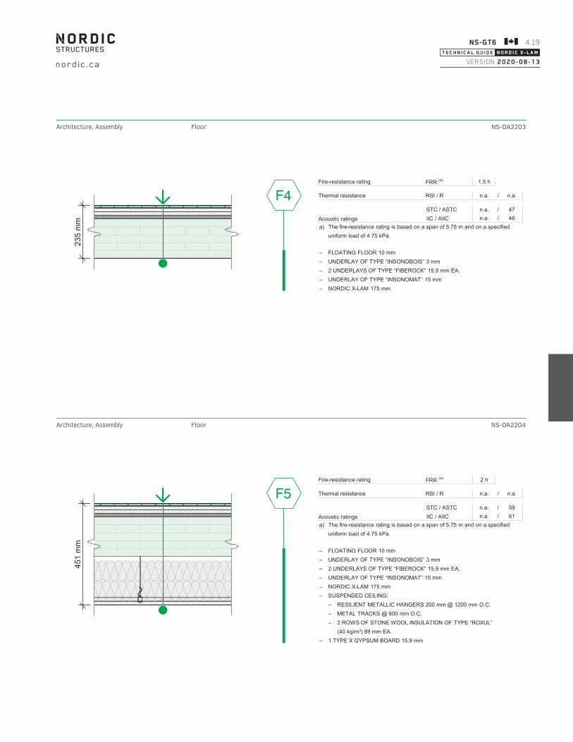
nordic .ca
NS-GT6 4.19T E C H N I C A L G U I D E N O R D I C X- L A M
VERSION 2020-08-13
DATE
2020-02-01
TITLE
CATEGORY SCALE
Architecture, Assembly 1:10PAGE
DRAWING
Floor NS-DA2203-CA-en
235
mm
F4
DATE
2020-02-01
TITLE
CATEGORY SCALE
Architecture, Assembly 1:10PAGE
DRAWING
Floor NS-DA2204-CA-en
451
mm
F5
Architecture, Assembly Floor NS-DA2203
Architecture, Assembly Floor NS-DA2204
Fire-resistance rating FRR (a) 1.5 h F4
Thermal resistance RSI / R n.a. / n.a. NS-DA2203-CA-en
n.a. / 47Acoustic ratings n.a. / 46
‒ FLOATING FLOOR 10 mm‒ UNDERLAY OF TYPE “INSONOBOIS” 3 mm‒ 2 UNDERLAYS OF TYPE “FIBEROCK” 15.9 mm EA.‒ UNDERLAY OF TYPE “INSONOMAT” 15 mm‒ NORDIC X-LAM 175 mm
STC / ASTCIIC / AIIC
a) The fire-resistance rating is based on a span of 5.75 m and on a specified uniform load of 4.75 kPa.
Fire-resistance rating FRR (a) 2 h F5
Thermal resistance RSI / R n.a. / n.a. NS-DA2204-CA-en
n.a. / 59Acoustic ratings n.a. / 61
‒ FLOATING FLOOR 10 mm‒ UNDERLAY OF TYPE “INSONOBOIS” 3 mm‒ 2 UNDERLAYS OF TYPE “FIBEROCK” 15.9 mm EA.‒ UNDERLAY OF TYPE “INSONOMAT” 15 mm‒ NORDIC X-LAM 175 mm‒ SUSPENDED CEILING:
‒ RESILIENT METALLIC HANGERS 200 mm @ 1200 mm O.C.‒ METAL TRACKS @ 600 mm O.C.‒ 2 ROWS OF STONE WOOL INSULATION OF TYPE “ROXUL”
(40 kg/m³) 89 mm EA.‒ 1 TYPE X GYPSUM BOARD 15.9 mm
STC / ASTCIIC / AIIC
a) The fire-resistance rating is based on a span of 5.75 m and on a specified uniform load of 4.75 kPa.
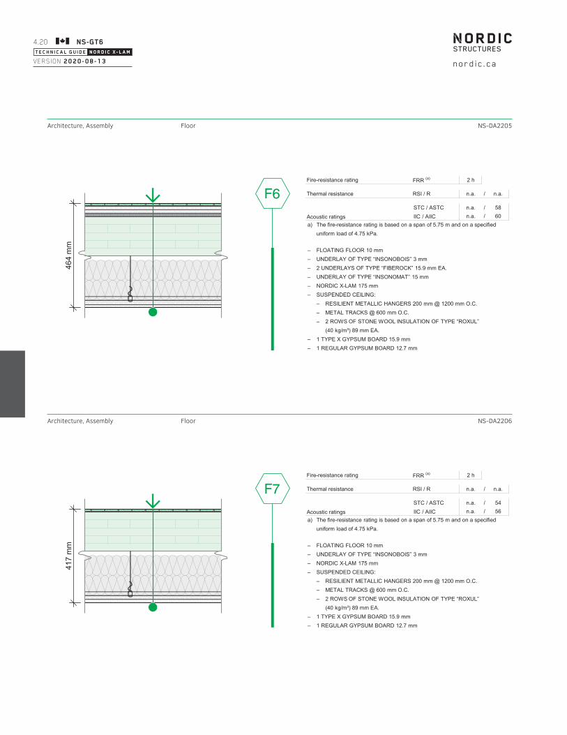
nordic .ca
4.20 NS-GT6 T E C H N I C A L G U I D E N O R D I C X- L A M
VERSION 2020-08-13
DATE
2020-02-01
TITLE
CATEGORY SCALE
Architecture, Assembly 1:10PAGE
DRAWING
Floor NS-DA2205-CA-en
464
mm
F6
DATE
2020-02-01
TITLE
CATEGORY SCALE
Architecture, Assembly 1:10PAGE
DRAWING
Floor NS-DA2206-CA-en
417
mm
F7
Architecture, Assembly Floor NS-DA2205
Architecture, Assembly Floor NS-DA2206
Fire-resistance rating FRR (a) 2 h F6
Thermal resistance RSI / R n.a. / n.a. NS-DA2205-CA-en
n.a. / 58Acoustic ratings n.a. / 60
‒ FLOATING FLOOR 10 mm‒ UNDERLAY OF TYPE “INSONOBOIS” 3 mm‒ 2 UNDERLAYS OF TYPE “FIBEROCK” 15.9 mm EA.‒ UNDERLAY OF TYPE “INSONOMAT” 15 mm‒ NORDIC X-LAM 175 mm‒ SUSPENDED CEILING:
‒ RESILIENT METALLIC HANGERS 200 mm @ 1200 mm O.C.‒ METAL TRACKS @ 600 mm O.C.‒ 2 ROWS OF STONE WOOL INSULATION OF TYPE “ROXUL”
(40 kg/m³) 89 mm EA.‒ 1 TYPE X GYPSUM BOARD 15.9 mm‒ 1 REGULAR GYPSUM BOARD 12.7 mm
STC / ASTCIIC / AIIC
a) The fire-resistance rating is based on a span of 5.75 m and on a specified uniform load of 4.75 kPa.
Fire-resistance rating FRR (a) 2 h F7
Thermal resistance RSI / R n.a. / n.a. NS-DA2206-CA-en
n.a. / 54Acoustic ratings n.a. / 56
‒ FLOATING FLOOR 10 mm‒ UNDERLAY OF TYPE “INSONOBOIS” 3 mm‒ NORDIC X-LAM 175 mm‒ SUSPENDED CEILING:
‒ RESILIENT METALLIC HANGERS 200 mm @ 1200 mm O.C.‒ METAL TRACKS @ 600 mm O.C.‒ 2 ROWS OF STONE WOOL INSULATION OF TYPE “ROXUL”
(40 kg/m³) 89 mm EA.‒ 1 TYPE X GYPSUM BOARD 15.9 mm‒ 1 REGULAR GYPSUM BOARD 12.7 mm
STC / ASTCIIC / AIIC
a) The fire-resistance rating is based on a span of 5.75 m and on a specified uniform load of 4.75 kPa.
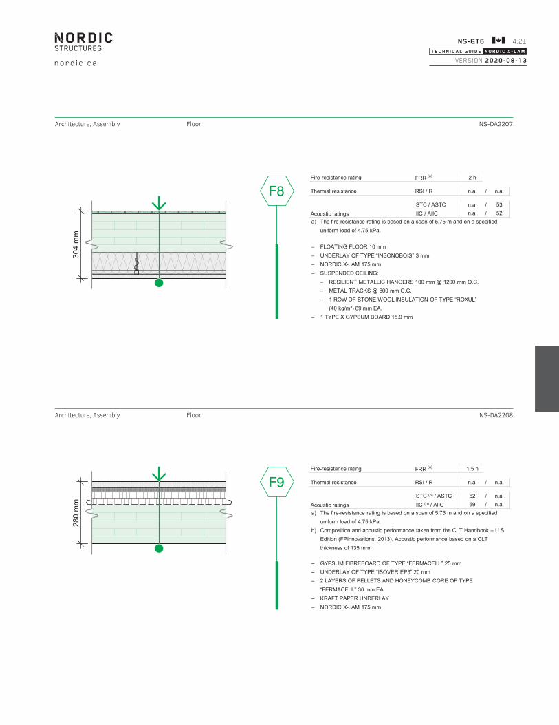
nordic .ca
NS-GT6 4.21T E C H N I C A L G U I D E N O R D I C X- L A M
VERSION 2020-08-13
DATE
2020-02-01
TITLE
CATEGORY SCALE
Architecture, Assembly 1:10PAGE
DRAWING
Floor NS-DA2207-CA-en
304
mm
F8
DATE
2020-02-01
TITLE
CATEGORY SCALE
Architecture, Assembly 1:10PAGE
DRAWING
Floor NS-DA2208-CA-en
280
mm
F9
Architecture, Assembly Floor NS-DA2207
Architecture, Assembly Floor NS-DA2208
Fire-resistance rating FRR (a) 2 h F8
Thermal resistance RSI / R n.a. / n.a. NS-DA2207-CA-en
n.a. / 53Acoustic ratings n.a. / 52
‒ FLOATING FLOOR 10 mm‒ UNDERLAY OF TYPE “INSONOBOIS” 3 mm‒ NORDIC X-LAM 175 mm‒ SUSPENDED CEILING:
‒ RESILIENT METALLIC HANGERS 100 mm @ 1200 mm O.C.‒ METAL TRACKS @ 600 mm O.C.‒ 1 ROW OF STONE WOOL INSULATION OF TYPE “ROXUL”
(40 kg/m³) 89 mm EA.‒ 1 TYPE X GYPSUM BOARD 15.9 mm
STC / ASTCIIC / AIIC
a) The fire-resistance rating is based on a span of 5.75 m and on a specified uniform load of 4.75 kPa.
Fire-resistance rating FRR (a) 1.5 h F9
Thermal resistance RSI / R n.a. / n.a. NS-DA2208-CA-en
62 / n.a.Acoustic ratings 59 / n.a.
‒ GYPSUM FIBREBOARD OF TYPE “FERMACELL” 25 mm‒ UNDERLAY OF TYPE “ISOVER EP3” 20 mm‒ 2 LAYERS OF PELLETS AND HONEYCOMB CORE OF TYPE
“FERMACELL” 30 mm EA.‒ KRAFT PAPER UNDERLAY‒ NORDIC X-LAM 175 mm
a) The fire-resistance rating is based on a span of 5.75 m and on a specified uniform load of 4.75 kPa.
b) Composition and acoustic performance taken from the CLT Handbook – U.S. Edition (FPInnovations, 2013). Acoustic performance based on a CLT thickness of 135 mm.
STC (b) / ASTCIIC (b) / AIIC
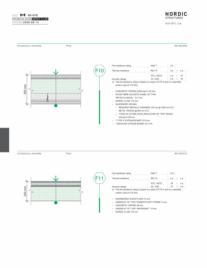
nordic .ca
4.22 NS-GT6 T E C H N I C A L G U I D E N O R D I C X- L A M
VERSION 2020-08-13
DATE
2020-02-01
TITLE
CATEGORY SCALE
Architecture, Assembly 1:10PAGE
DRAWING
Floor NS-DA2209-CA-en
355
mm
F10
DATE
2020-02-01
TITLE
CATEGORY SCALE
Architecture, Assembly 1:10PAGE
DRAWING
Floor NS-DA2210-CA-en
240
mm
F11
Architecture, Assembly Floor NS-DA2209
Architecture, Assembly Floor NS-DA2210
Fire-resistance rating FRR (a) 2 h F10
Thermal resistance RSI / R n.a. / n.a. NS-DA2209-CA-en
n.a. / 61Acoustic ratings n.a. / 50
‒ CONCRETE TOPPING (2000 kg/m³) 38 mm‒ WOOD FIBRE ACOUSTIC PANEL OF TYPE
“BP ECO-LOGICAL” 12.7 mm‒ NORDIC X-LAM 175 mm‒ SUSPENDED CEILING:
‒ RESILIENT METALLIC HANGERS 100 mm @ 1200 mm O.C.‒ METAL TRACKS @ 600 mm O.C.‒ 1 ROW OF STONE WOOL INSULATION OF TYPE “ROXUL”
(40 kg/m³) 89 mm ‒ 1 TYPE X GYPSUM BOARD 15.9 mm‒ 1 REGULAR GYPSUM BOARD 12.7 mm
STC / ASTCIIC / AIIC
a) The fire-resistance rating is based on a span of 5.75 m and on a specified uniform load of 4.75 kPa.
Fire-resistance rating FRR (a) 1.5 h F11
Thermal resistance RSI / R n.a. / n.a. NS-DA2210-CA-en
55 / n.a.Acoustic ratings 51 / n.a.
‒ ENGINEERED WOOD FLOOR 10 mm‒ UNDERLAY OF TYPE “ROBERTS SOFT STRIDE” 2 mm‒ CONCRETE TOPPING 38 mm‒ UNDERLAY OF TYPE “INSONOMAT” 15 mm‒ NORDIC X-LAM 175 mm
STC / ASTCIIC / AIIC
a) The fire-resistance rating is based on a span of 5.75 m and on a specified uniform load of 4.75 kPa.
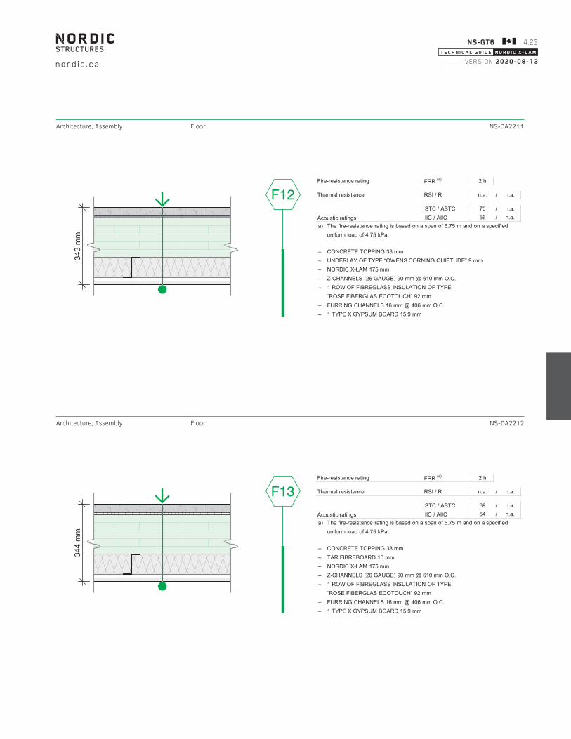
nordic .ca
NS-GT6 4.23T E C H N I C A L G U I D E N O R D I C X- L A M
VERSION 2020-08-13
DATE
2020-02-01
TITLE
CATEGORY SCALE
Architecture, Assembly 1:10PAGE
DRAWING
Floor NS-DA2211-CA-en
343
mm
F12
DATE
2020-02-01
TITLE
CATEGORY SCALE
Architecture, Assembly 1:10PAGE
DRAWING
Floor NS-DA2212-CA-en
344
mm
F13
Architecture, Assembly Floor NS-DA2211
Architecture, Assembly Floor NS-DA2212
Fire-resistance rating FRR (a) 2 h F12
Thermal resistance RSI / R n.a. / n.a. NS-DA2211-CA-en
70 / n.a.Acoustic ratings 56 / n.a.
‒ CONCRETE TOPPING 38 mm‒ UNDERLAY OF TYPE “OWENS CORNING QUIÉTUDE” 9 mm‒ NORDIC X-LAM 175 mm‒ Z-CHANNELS (26 GAUGE) 90 mm @ 610 mm O.C.‒ 1 ROW OF FIBREGLASS INSULATION OF TYPE
“ROSE FIBERGLAS ECOTOUCH” 92 mm‒ FURRING CHANNELS 16 mm @ 406 mm O.C.‒ 1 TYPE X GYPSUM BOARD 15.9 mm
STC / ASTCIIC / AIIC
a) The fire-resistance rating is based on a span of 5.75 m and on a specified uniform load of 4.75 kPa.
Fire-resistance rating FRR (a) 2 h F13
Thermal resistance RSI / R n.a. / n.a. NS-DA2212-CA-en
69 / n.a.Acoustic ratings 54 / n.a.
‒ CONCRETE TOPPING 38 mm‒ TAR FIBREBOARD 10 mm‒ NORDIC X-LAM 175 mm‒ Z-CHANNELS (26 GAUGE) 90 mm @ 610 mm O.C.‒ 1 ROW OF FIBREGLASS INSULATION OF TYPE
“ROSE FIBERGLAS ECOTOUCH” 92 mm‒ FURRING CHANNELS 16 mm @ 406 mm O.C. ‒ 1 TYPE X GYPSUM BOARD 15.9 mm
STC / ASTCIIC / AIIC
a) The fire-resistance rating is based on a span of 5.75 m and on a specified uniform load of 4.75 kPa.
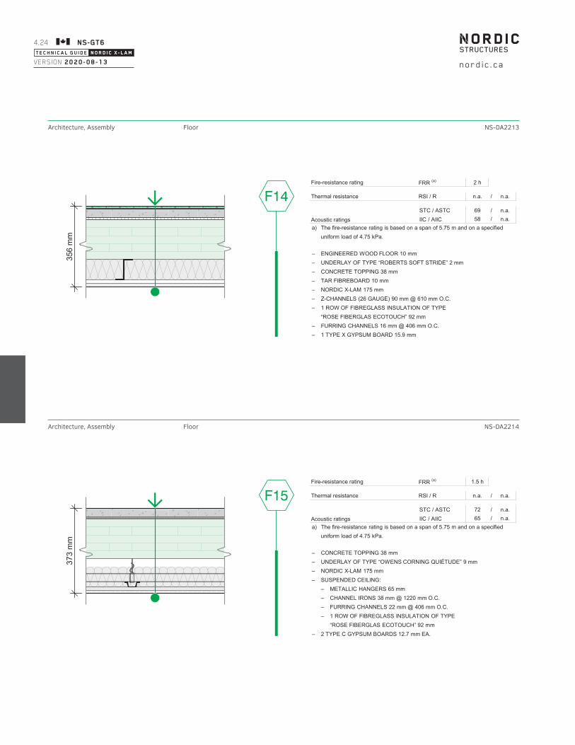
nordic .ca
4.24 NS-GT6 T E C H N I C A L G U I D E N O R D I C X- L A M
VERSION 2020-08-13
DATE
2020-02-01
TITLE
CATEGORY SCALE
Architecture, Assembly 1:10PAGE
DRAWING
Floor NS-DA2213-CA-en
356
mm
F14
DATE
2020-02-01
TITLE
CATEGORY SCALE
Architecture, Assembly 1:10PAGE
DRAWING
Floor NS-DA2214-CA-en
373
mm
F15
Architecture, Assembly Floor NS-DA2213
Architecture, Assembly Floor NS-DA2214
Fire-resistance rating FRR (a) 2 h F14
Thermal resistance RSI / R n.a. / n.a. NS-DA2213-CA-en
69 / n.a.Acoustic ratings 58 / n.a.
‒ ENGINEERED WOOD FLOOR 10 mm‒ UNDERLAY OF TYPE “ROBERTS SOFT STRIDE” 2 mm‒ CONCRETE TOPPING 38 mm‒ TAR FIBREBOARD 10 mm‒ NORDIC X-LAM 175 mm‒ Z-CHANNELS (26 GAUGE) 90 mm @ 610 mm O.C.‒ 1 ROW OF FIBREGLASS INSULATION OF TYPE
“ROSE FIBERGLAS ECOTOUCH” 92 mm‒ FURRING CHANNELS 16 mm @ 406 mm O.C.‒ 1 TYPE X GYPSUM BOARD 15.9 mm
STC / ASTCIIC / AIIC
a) The fire-resistance rating is based on a span of 5.75 m and on a specified uniform load of 4.75 kPa.
Fire-resistance rating FRR (a) 1.5 h F15
Thermal resistance RSI / R n.a. / n.a. NS-DA2214-CA-en
72 / n.a.Acoustic ratings 65 / n.a.
‒ CONCRETE TOPPING 38 mm‒ UNDERLAY OF TYPE “OWENS CORNING QUIÉTUDE” 9 mm‒ NORDIC X-LAM 175 mm‒ SUSPENDED CEILING:
‒ METALLIC HANGERS 65 mm‒ CHANNEL IRONS 38 mm @ 1220 mm O.C.‒ FURRING CHANNELS 22 mm @ 406 mm O.C.‒ 1 ROW OF FIBREGLASS INSULATION OF TYPE
“ROSE FIBERGLAS ECOTOUCH” 92 mm‒ 2 TYPE C GYPSUM BOARDS 12.7 mm EA.
STC / ASTCIIC / AIIC
a) The fire-resistance rating is based on a span of 5.75 m and on a specified uniform load of 4.75 kPa.
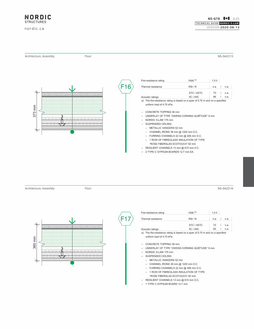
nordic .ca
NS-GT6 4.25T E C H N I C A L G U I D E N O R D I C X- L A M
VERSION 2020-08-13
DATE
2020-02-01
TITLE
CATEGORY SCALE
Architecture, Assembly 1:10PAGE
DRAWING
Floor NS-DA2215-CA-en
373
mm
F16
DATE
2020-02-01
TITLE
CATEGORY SCALE
Architecture, Assembly 1:10PAGE
DRAWING
Floor NS-DA2216-CA-en
360
mm
F17
Architecture, Assembly Floor NS-DA2215
Architecture, Assembly Floor NS-DA2216
Fire-resistance rating FRR (a) 1.5 h F16
Thermal resistance RSI / R n.a. / n.a. NS-DA2215-CA-en
73 / n.a.Acoustic ratings 66 / n.a.
‒ CONCRETE TOPPING 38 mm‒ UNDERLAY OF TYPE “OWENS CORNING QUIÉTUDE” 9 mm‒ NORDIC X-LAM 175 mm‒ SUSPENDED CEILING:
‒ METALLIC HANGERS 52 mm‒ CHANNEL IRONS 38 mm @ 1220 mm O.C.‒ FURRING CHANNELS 22 mm @ 406 mm O.C.‒ 1 ROW OF FIBREGLASS INSULATION OF TYPE
“ROSE FIBERGLAS ECOTOUCH” 92 mm‒ RESILIENT CHANNELS 13 mm @ 610 mm O.C.‒ 2 TYPE C GYPSUM BOARDS 12.7 mm EA.
STC / ASTCIIC / AIIC
a) The fire-resistance rating is based on a span of 5.75 m and on a specified uniform load of 4.75 kPa.
Fire-resistance rating FRR (a) 1.5 h F17
Thermal resistance RSI / R n.a. / n.a. NS-DA2216-CA-en
72 / n.a.Acoustic ratings 62 / n.a.
‒ CONCRETE TOPPING 38 mm‒ UNDERLAY OF TYPE “OWENS CORNING QUIÉTUDE” 9 mm‒ NORDIC X-LAM 175 mm‒ SUSPENDED CEILING:
‒ METALLIC HANGERS 52 mm‒ CHANNEL IRONS 38 mm @ 1220 mm O.C.‒ FURRING CHANNELS 22 mm @ 406 mm O.C.‒ 1 ROW OF FIBREGLASS INSULATION OF TYPE
“ROSE FIBERGLAS ECOTOUCH” 92 mm‒ RESILIENT CHANNELS 13 mm @ 610 mm O.C.‒ 1 TYPE C GYPSUM BOARD 12.7 mm
STC / ASTCIIC / AIIC
a) The fire-resistance rating is based on a span of 5.75 m and on a specified uniform load of 4.75 kPa.

nordic .ca
4.26 NS-GT6 T E C H N I C A L G U I D E N O R D I C X- L A M
VERSION 2020-08-13
DATE
2020-02-01
TITLE
CATEGORY SCALE
Architecture, Assembly 1:10PAGE
DRAWING
Floor NS-DA2217-CA-en
466
mm
F18
DATE
2020-02-01
TITLE
CATEGORY SCALE
Architecture, Assembly 1:10PAGE
DRAWING
Floor NS-DA2219-CA-en
421
mm
F20
Architecture, Assembly Floor NS-DA2217
Architecture, Assembly Floor NS-DA2219
Fire-resistance rating FRR (a) 1.5 h F18
Thermal resistance RSI / R n.a. / n.a. NS-DA2217-CA-en
75 / n.a.Acoustic ratings 66 / n.a.
‒ FLOATING FLOOR 9 mm‒ UNDERLAY OF TYPE “ACOUSTITECH PREMIUM” 3 mm‒ PREFABRICATED CONCRETE TOPPING 38 mm‒ TAR FIBREBOARD 10 mm‒ NORDIC X-LAM 175 mm‒ SUSPENDED CEILING:
‒ METALLIC HANGERS 145 mm‒ CHANNEL IRONS 38 mm @ 1220 mm O.C.‒ FURRING CHANNELS 22 mm @ 406 mm O.C.‒ 1 ROW OF FIBREGLASS INSULATION OF TYPE
“ROSE FIBERGLAS ECOTOUCH” 92 mm‒ 2 TYPE C GYPSUM BOARDS 12.7 mm EA.
a) The fire-resistance rating is based on a span of 5.75 m and on a specified uniform load of 4.75 kPa.
b) Acoustic performance based on a CLT thickness of 131 mm.
STC (b) / ASTCIIC (b) / AIIC
Fire-resistance rating FRR (a) 2 h F20
Thermal resistance RSI / R n.a. / n.a. NS-DA2219-CA-en
61 / n.a.Acoustic ratings 55 / n.a.
‒ 2 ROWS OF PANELS OF TYPE “HUBER ENGINEERED WOOD ADVANTECH” 36 mm EA.
‒ UNDERLAY OF TYPE “GENIEMAT FF” 25 mm‒ NORDIC X-LAM 175 mm‒ SUSPENDED CEILING:
‒ BRACKETS OF TYPE “GENIECLIP LB” 111 mm‒ CHANNEL IRONS 38 mm @ 1220 mm O.C. FIXED AT THE BOTTOM OF
THE BRACKETS ‒ FURRING CHANNELS 22 mm @ 610 mm O.C.‒ 1 ROW FIBREGLASS INSULATION OF TYPE
“JOHNS MANVILLE UNFACED BATTS R13” 89 mm‒ 1 TYPE X GYPSUM BOARD 15.9 mm
STC / ASTCIIC / AIIC
a) The fire-resistance rating is based on a span of 5.75 m and on a specified uniform load of 4.75 kPa.
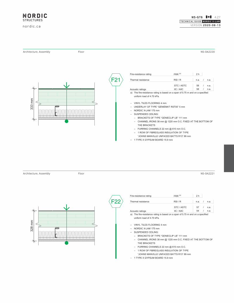
nordic .ca
NS-GT6 4.27T E C H N I C A L G U I D E N O R D I C X- L A M
VERSION 2020-08-13
DATE
2020-02-01
TITLE
CATEGORY SCALE
Architecture, Assembly 1:10PAGE
DRAWING
Floor NS-DA2220-CA-en
333
mm
F21
DATE
2020-02-01
TITLE
CATEGORY SCALE
Architecture, Assembly 1:10PAGE
DRAWING
Floor NS-DA2221-CA-en
328
mm
F22
Architecture, Assembly Floor NS-DA2220
Architecture, Assembly Floor NS-DA2221
Fire-resistance rating FRR (a) 2 h F21
Thermal resistance RSI / R n.a. / n.a. NS-DA2220-CA-en
58 / n.a.Acoustic ratings 58 / n.a.
‒ VINYL TILES FLOORING 4 mm‒ UNDERLAY OF TYPE “GENIEMAT RST05” 5 mm‒ NORDIC X-LAM 175 mm‒ SUSPENDED CEILING:
‒ BRACKETS OF TYPE “GENIECLIP LB” 111 mm‒ CHANNEL IRONS 38 mm @ 1220 mm O.C. FIXED AT THE BOTTOM OF
THE BRACKETS ‒ FURRING CHANNELS 22 mm @ 610 mm O.C.‒ 1 ROW OF FIBREGLASS INSULATION OF TYPE
“JOHNS MANVILLE UNFACED BATTS R13” 89 mm‒ 1 TYPE X GYPSUM BOARD 15.9 mm
STC / ASTCIIC / AIIC
a) The fire-resistance rating is based on a span of 5.75 m and on a specified uniform load of 4.75 kPa.
Fire-resistance rating FRR (a) 2 h F22
Thermal resistance RSI / R n.a. / n.a. NS-DA2221-CA-en
57 / n.a.Acoustic ratings 54 / n.a.
‒ VINYL TILES FLOORING 4 mm‒ NORDIC X-LAM 175 mm‒ SUSPENDED CEILING:
‒ BRACKETS OF TYPE “GENIECLIP LB” 111 mm‒ CHANNEL IRONS 38 mm @ 1220 mm O.C. FIXED AT THE BOTTOM OF
THE BRACKETS ‒ FURRING CHANNELS 22 mm @ 610 mm O.C.‒ 1 ROW OF FIBREGLASS INSULATION OF TYPE
“JOHNS MANVILLE UNFACED BATTS R13” 89 mm‒ 1 TYPE X GYPSUM BOARD 15.9 mm
STC / ASTCIIC / AIIC
a) The fire-resistance rating is based on a span of 5.75 m and on a specified uniform load of 4.75 kPa.
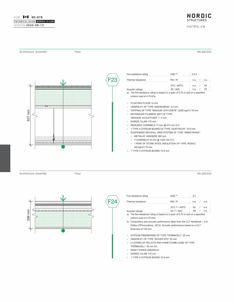
nordic .ca
4.28 NS-GT6 T E C H N I C A L G U I D E N O R D I C X- L A M
VERSION 2020-08-13
DATE
2020-02-01
TITLE
CATEGORY SCALE
Architecture, Assembly 1:10PAGE
DRAWING
Floor NS-DA2222-CA-en
637
mm
F23
DATE
2020-02-01
TITLE
CATEGORY SCALE
Architecture, Assembly 1:10PAGE
DRAWING
Floor NS-DA2223-CA-en
296
mm
F24
Architecture, Assembly Floor NS-DA2222
Architecture, Assembly Floor NS-DA2223
Fire-resistance rating FRR (a) 2.5 h F23
Thermal resistance RSI / R n.a. / n.a. NS-DA2222-CA-en
n.a. / 54Acoustic ratings n.a. / 53
‒ FLOATING FLOOR 10 mm‒ UNDERLAY OF TYPE “INSONOBOIS” 3.5 mm‒ TOPPING OF TYPE “MAXXON GYP-CRETE” (2050 kg/m³) 19 mm‒ ENTANGLED FILAMENT MAT OF TYPE
“MAXXON ACOUSTI-MAT 1” 5 mm‒ NORDIC X-LAM 175 mm‒ RESILIENT CHANNELS 13 mm @ 610 mm O.C.‒ 1 TYPE X GYPSUM BOARD OF TYPE “QUIETROCK” 15.9 mm‒ SUSPENDED DRYWALL GRID SYSTEM OF TYPE “ARMSTRONG”:
‒ METALLIC HANGERS 380 mm‒ T-CHANNELS 43 mm @ 1220 mm O.C. ‒ 1 ROW OF STONE WOOL INSULATION OF TYPE “ROXUL”
(40 kg/m³) 75 mm‒ 1 TYPE X GYPSUM BOARD 15.9 mm
STC / ASTCIIC / AIIC
a) The fire-resistance rating is based on a span of 5.75 m and on a specified uniform load of 4.75 kPa.
Fire-resistance rating FRR (a) 2 h F24
Thermal resistance RSI / R n.a. / n.a. NS-DA2223-CA-en
62 / n.a.Acoustic ratings 59 / n.a.
‒ GYPSUM FIBERBOARD OF TYPE “FERMACELL” 25 mm‒ UNDERLAY OF TYPE “ISOVER EP3” 20 mm‒ 2 LAYERS OF PELLETS AND HONEYCOMB CORE OF TYPE
“FERMACELL” 30 mm EA.‒ KRAFT PAPER UNDERLAY‒ NORDIC X-LAM 175 mm‒ 1 TYPE X GYPSUM BOARD 15.9 mm
STC (b) / ASTCIIC (b) / AIIC
a) The fire-resistance rating is based on a span of 5.75 m and on a specified uniform load of 4.75 kPa.
b) Composition and acoustic performance taken from the CLT Handbook – U.S. Edition (FPInnovations, 2013). Acoustic performance based on a CLT thickness of 135 mm.

nordic .ca
NS-GT6 4.29T E C H N I C A L G U I D E N O R D I C X- L A M
VERSION 2020-08-13
DATE
2020-02-01
TITLE
CATEGORY SCALE
Architecture, Assembly 1:10PAGE
DRAWING
Floor NS-DA2224-CA-en
236
mm
@ 2
44 m
m F25
DATE
2020-02-01
TITLE
CATEGORY SCALE
Architecture, Assembly 1:10PAGE
DRAWING
Floor NS-DA2225-CA-en
252
mm
@ 2
60 m
m
F26
Architecture, Assembly Floor NS-DA2224
Architecture, Assembly Floor NS-DA2225
Fire-resistance rating FRR (a) 1.5 h F25
Thermal resistance RSI / R n.a. / n.a. NS-DA2224-CA-en
n.a. / > 50Acoustic ratings n.a. / > 50
‒ CARPET OR FLOATING FLOOR 10 mm‒ RESILIENT UNDERLAY (RUBBER OR FELT) 3 mm‒ TOPPING, AT LEAST 76 kg/m² (I.E. CONCRETE OR OF TYPE
“MAXXON GYP-CRETE”)‒ RESILIENT UNDERLAY (RUBBER 10 mm, FELT 18 mm, OR WOOD
FIBERBOARD 12 mm)‒ NORDIC X-LAM 175 mm
STC / ASTC (b)
IIC / AIIC (b)
a) The fire-resistance rating is based on a span of 5.75 m and on a specified uniform load of 4.75 kPa.
b) Composition and acoustic performance taken from the CLT Handbook – U.S. Edition (FPInnovations, 2013). Acoustic performance based on a CLT thickness of 135 mm.
Fire-resistance rating FRR (a) 2 h F26
Thermal resistance RSI / R n.a. / n.a. NS-DA2225-CA-en
n.a. / > 50Acoustic ratings n.a. / > 50
‒ CARPET OR FLOATING FLOOR 10 mm‒ RESILIENT UNDERLAY (RUBBER OR FELT) 3 mm‒ TOPPING, AT LEAST 76 kg/m² (I.E. CONCRETE OR OF TYPE
“MAXXON GYP-CRETE”)‒ RESILIENT UNDERLAY (RUBBER 10 mm, FELT 18 mm, OR WOOD
FIBERBOARD 12 mm)‒ NORDIC X-LAM 175 mm‒ 1 TYPE X GYPSUM BOARD 15.9 mm
STC / ASTC (b)
IIC / AIIC (b)
a) The fire-resistance rating is based on a span of 5.75 m and on a specified uniform load of 4.75 kPa.
b) Composition and acoustic performance taken from the CLT Handbook – U.S. Edition (FPInnovations, 2013). Acoustic performance based on a CLT thickness of 135 mm.

nordic .ca
4.30 NS-GT6 T E C H N I C A L G U I D E N O R D I C X- L A M
VERSION 2020-08-13
DATE
2020-02-01
TITLE
CATEGORY SCALE
Architecture, Assembly 1:10PAGE
DRAWING
Floor NS-DA2226-CA-en
218
mm
@ 2
26 m
m
F27
DATE
2020-02-01
TITLE
CATEGORY SCALE
Architecture, Assembly 1:10PAGE
DRAWING
Floor NS-DA2227-CA-en
234
mm
@ 2
42 m
m
F28
Architecture, Assembly Floor NS-DA2226
Architecture, Assembly Floor NS-DA2227
Fire-resistance rating FRR (a) 1.5 h F27
Thermal resistance RSI / R n.a. / n.a. NS-DA2226-CA-en
n.a. / > 45Acoustic ratings n.a. / > 45
‒ CARPET OR FLOATING FLOOR 10 mm‒ RESILIENT UNDERLAY (RUBBER OR FELT) 3 mm‒ PREFABRICATED TOPPING, AT LEAST 25 kg/m² (20 mm OF TYPE
“FERMACELL” OR OF TYPE “FIBREROCK”)‒ RESILIENT UNDERLAY (RUBBER 10 mm, FELT 18 mm, OR WOOD
FIBERBOARD 12 mm)‒ NORDIC X-LAM 175 mm
STC / ASTC (b)
IIC / AIIC (b)
a) The fire-resistance rating is based on a span of 5.75 m and on a specified uniform load of 4.75 kPa.
b) Composition and acoustic performance taken from the CLT Handbook – U.S. Edition (FPInnovations, 2013). Acoustic performance based on a CLT thickness of 135 mm.
Fire-resistance rating FRR (a) 2 h F28
Thermal resistance RSI / R n.a. / n.a. NS-DA2227-CA-en
n.a. / > 45Acoustic ratings n.a. / > 45
‒ CARPET OR FLOATING FLOOR 10 mm‒ RESILIENT UNDERLAY (RUBBER OR FELT) 3 mm‒ PREFABRICATED TOPPING, AT LEAST 25 kg/m² (20 mm OF TYPE
“FERMACELL” OR OF TYPE “FIBREROCK”)‒ RESILIENT UNDERLAY (RUBBER 10 mm, FELT 18 mm, OR WOOD
FIBERBOARD 12 mm)‒ NORDIC X-LAM 175 mm‒ 1 TYPE X GYPSUM BOARD 15.9 mm
STC / ASTC (b)
IIC / AIIC (b)
a) The fire-resistance rating is based on a span of 5.75 m and on a specified uniform load of 4.75 kPa.
b) Composition and acoustic performance taken from the CLT Handbook – U.S. Edition (FPInnovations, 2013). Acoustic performance based on a CLT thickness of 135 mm.
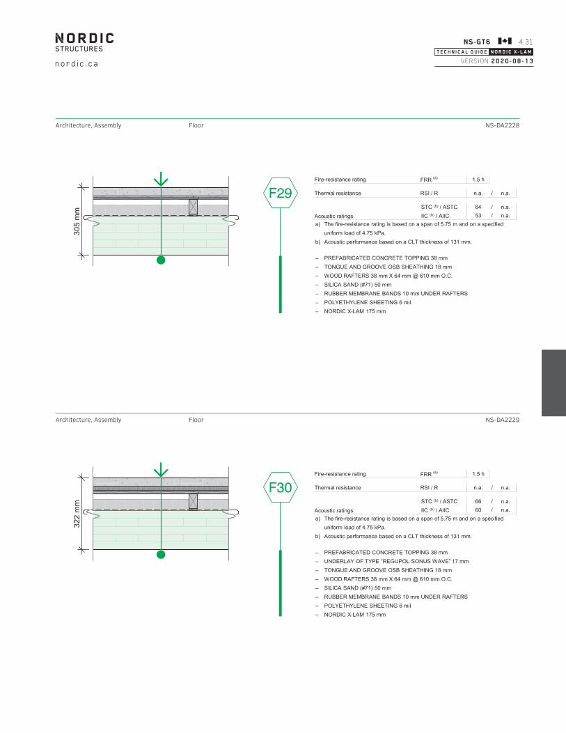
nordic .ca
NS-GT6 4.31T E C H N I C A L G U I D E N O R D I C X- L A M
VERSION 2020-08-13
DATE
2020-02-01
TITLE
CATEGORY SCALE
Architecture, Assembly 1:10PAGE
DRAWING
Floor NS-DA2228-CA-en
305
mm
F29
DATE
2020-02-01
TITLE
CATEGORY SCALE
Architecture, Assembly 1:10PAGE
DRAWING
Floor NS-DA2229-CA-en
322
mm
F30
Architecture, Assembly Floor NS-DA2228
Architecture, Assembly Floor NS-DA2229
Fire-resistance rating FRR (a) 1.5 h F29
Thermal resistance RSI / R n.a. / n.a. NS-DA2228-CA-en
64 / n.a.Acoustic ratings 53 / n.a.
‒ PREFABRICATED CONCRETE TOPPING 38 mm‒ TONGUE AND GROOVE OSB SHEATHING 18 mm‒ WOOD RAFTERS 38 mm X 64 mm @ 610 mm O.C. ‒ SILICA SAND (#71) 50 mm‒ RUBBER MEMBRANE BANDS 10 mm UNDER RAFTERS‒ POLYETHYLENE SHEETING 6 mil‒ NORDIC X-LAM 175 mm
STC (b) / ASTCIIC (b) / AIIC
a) The fire-resistance rating is based on a span of 5.75 m and on a specified uniform load of 4.75 kPa.
b) Acoustic performance based on a CLT thickness of 131 mm.
Fire-resistance rating FRR (a) 1.5 h F30
Thermal resistance RSI / R n.a. / n.a. NS-DA2229-CA-en
66 / n.a.Acoustic ratings 60 / n.a.
‒ PREFABRICATED CONCRETE TOPPING 38 mm‒ UNDERLAY OF TYPE “REGUPOL SONUS WAVE” 17 mm‒ TONGUE AND GROOVE OSB SHEATHING 18 mm‒ WOOD RAFTERS 38 mm X 64 mm @ 610 mm O.C.‒ SILICA SAND (#71) 50 mm‒ RUBBER MEMBRANE BANDS 10 mm UNDER RAFTERS‒ POLYETHYLENE SHEETING 6 mil‒ NORDIC X-LAM 175 mm
STC (b) / ASTCIIC (b) / AIIC
a) The fire-resistance rating is based on a span of 5.75 m and on a specified uniform load of 4.75 kPa.
b) Acoustic performance based on a CLT thickness of 131 mm.
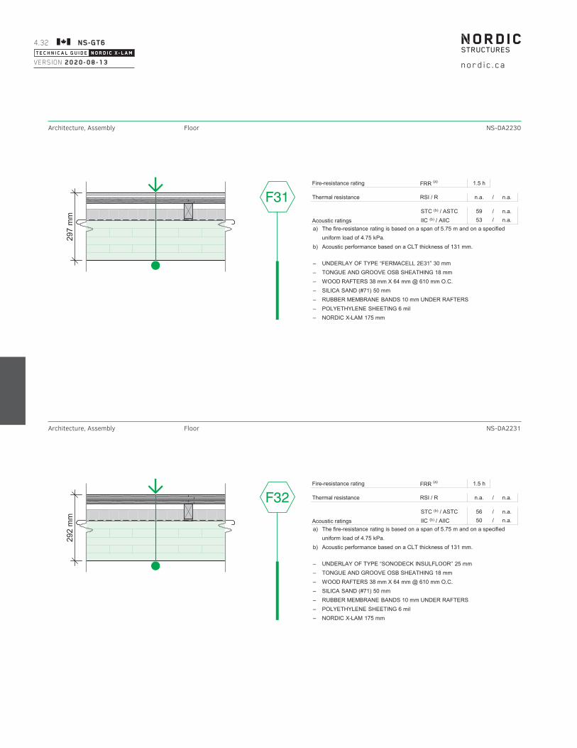
nordic .ca
4.32 NS-GT6 T E C H N I C A L G U I D E N O R D I C X- L A M
VERSION 2020-08-13
DATE
2020-02-01
TITLE
CATEGORY SCALE
Architecture, Assembly 1:10PAGE
DRAWING
Floor NS-DA2230-CA-en
297
mm
F31
DATE
2020-02-01
TITLE
CATEGORY SCALE
Architecture, Assembly 1:10PAGE
DRAWING
Floor NS-DA2231-CA-en
292
mm
F32
Architecture, Assembly Floor NS-DA2230
Architecture, Assembly Floor NS-DA2231
Fire-resistance rating FRR (a) 1.5 h F31
Thermal resistance RSI / R n.a. / n.a. NS-DA2230-CA-en
59 / n.a.Acoustic ratings 53 / n.a.
‒ UNDERLAY OF TYPE “FERMACELL 2E31” 30 mm‒ TONGUE AND GROOVE OSB SHEATHING 18 mm‒ WOOD RAFTERS 38 mm X 64 mm @ 610 mm O.C.‒ SILICA SAND (#71) 50 mm‒ RUBBER MEMBRANE BANDS 10 mm UNDER RAFTERS‒ POLYETHYLENE SHEETING 6 mil‒ NORDIC X-LAM 175 mm
STC (b) / ASTCIIC (b) / AIIC
a) The fire-resistance rating is based on a span of 5.75 m and on a specified uniform load of 4.75 kPa.
b) Acoustic performance based on a CLT thickness of 131 mm.
Fire-resistance rating FRR (a) 1.5 h F32
Thermal resistance RSI / R n.a. / n.a. NS-DA2231-CA-en
56 / n.a.Acoustic ratings 50 / n.a.
‒ UNDERLAY OF TYPE “SONODECK INSULFLOOR” 25 mm‒ TONGUE AND GROOVE OSB SHEATHING 18 mm‒ WOOD RAFTERS 38 mm X 64 mm @ 610 mm O.C.‒ SILICA SAND (#71) 50 mm‒ RUBBER MEMBRANE BANDS 10 mm UNDER RAFTERS‒ POLYETHYLENE SHEETING 6 mil‒ NORDIC X-LAM 175 mm
STC (b) / ASTCIIC (b) / AIIC
a) The fire-resistance rating is based on a span of 5.75 m and on a specified uniform load of 4.75 kPa.
b) Acoustic performance based on a CLT thickness of 131 mm.

nordic .ca
NS-GT6 4.33T E C H N I C A L G U I D E N O R D I C X- L A M
VERSION 2020-08-13
DATE
2020-02-01
TITLE
CATEGORY SCALE
Architecture, Assembly 1:10PAGE
DRAWING
Floor NS-DA2232-CA-en
322
mm
F33
DATE
2020-02-01
TITLE
CATEGORY SCALE
Architecture, Assembly 1:10PAGE
DRAWING
Floor NS-DA2233-CA-en
322
mm
F34
Architecture, Assembly Floor NS-DA2232
Architecture, Assembly Floor NS-DA2233
Fire-resistance rating FRR (a) 1.5 h F33
Thermal resistance RSI / R n.a. / n.a. NS-DA2232-CA-en
59 / n.a.Acoustic ratings 54 / n.a.
‒ PREFABRICATED CONCRETE TOPPING 38 mm‒ UNDERLAY OF TYPE “REGUPOL SONUS WAVE” 17 mm‒ TONGUE AND GROOVE OSB SHEATHING 18 mm‒ WOOD RAFTERS 38 mm X 64 mm @ 610 mm O.C.‒ RUBBER MEMBRANE BANDS 10 mm UNDER RAFTERS‒ NORDIC X-LAM 175 mm
STC (b) / ASTCIIC (b) / AIIC
a) The fire-resistance rating is based on a span of 5.75 m and on a specified uniform load of 4.75 kPa.
b) Acoustic performance based on a CLT thickness of 131 mm.
Fire-resistance rating FRR (a) 1.5 h F34
Thermal resistance RSI / R n.a. / n.a. NS-DA2233-CA-en
60 / n.a.Acoustic ratings 54 / n.a.
‒ PREFABRICATED CONCRETE TOPPING 38 mm‒ UNDERLAY OF TYPE “REGUPOL SONUS WAVE” 17 mm‒ TONGUE AND GROOVE OSB SHEATHING 18 mm‒ WOOD RAFTERS 38 mm X 64 mm @ 610 mm O.C.‒ 1 ROW OF FIBERGLASS INSULATION 65 mm‒ RUBBER MEMBRANE BANDS 10 mm UNDER RAFTERS‒ NORDIC X-LAM 175 mm
STC (b) / ASTCIIC (b) / AIIC
a) The fire-resistance rating is based on a span of 5.75 m and on a specified uniform load of 4.75 kPa.
b) Acoustic performance based on a CLT thickness of 131 mm.

nordic .ca
4.34 NS-GT6 T E C H N I C A L G U I D E N O R D I C X- L A M
VERSION 2020-08-13
DATE
2020-02-01
TITLE
CATEGORY SCALE
Architecture, Assembly 1:10PAGE
DRAWING
Floor NS-DA2235-CA-en
300
mm
F36
DATE
2020-02-01
TITLE
CATEGORY SCALE
Architecture, Assembly 1:10PAGE
DRAWING
Floor NS-DA2236-CA-en
288
mm
F37
Architecture, Assembly Floor NS-DA2235
Architecture, Assembly Floor NS-DA2236
Fire-resistance rating FRR (a) 1.5 h F36
Thermal resistance RSI / R n.a. / n.a. NS-DA2235-CA-en
56 / n.a.Acoustic ratings 52 / n.a.
‒ UNDERLAY OF TYPE “FERMACELL 2E31” 30 mm‒ PREFABRICATED CONCRETE TOPPING (2350 kg/m³) 70 mm‒ UNDERLAY OF TYPE “REGUPOL SONUS WAVE” 25 mm‒ NORDIC X-LAM 175 mm
STC (b) / ASTCIIC (b) / AIIC
a) The fire-resistance rating is based on a span of 5.75 m and on a specified uniform load of 4.75 kPa.
b) Acoustic performance based on a CLT thickness of 131 mm.
Fire-resistance rating FRR (a) 1.5 h F37
Thermal resistance RSI / R n.a. / n.a. NS-DA2236-CA-en
57 / n.a.Acoustic ratings 51 / n.a.
‒ LAMINATED FLOORING 8 mm‒ UNDERLAY OF TYPE “ACOUSTITECH PREMIUM” 3 mm‒ PREFABRICATED CONCRETE TOPPING (2350 kg/m³) 70 mm‒ RIGID SHEATHING BOARD OF TYPE
“ROXUL COMFORTBOARD IS” 32 mm‒ NORDIC X-LAM 175 mm
STC (b) / ASTCIIC (b) / AIIC
a) The fire-resistance rating is based on a span of 5.75 m and on a specified uniform load of 4.75 kPa.
b) Acoustic performance based on a CLT thickness of 131 mm.

nordic .ca
NS-GT6 4.35T E C H N I C A L G U I D E N O R D I C X- L A M
VERSION 2020-08-13
DATE
2020-02-01
TITLE
CATEGORY SCALE
Architecture, Assembly 1:10PAGE
DRAWING
Floor NS-DA2237-CA-en
287
mm
F38
DATE
2020-02-01
TITLE
CATEGORY SCALE
Architecture, Assembly 1:10PAGE
DRAWING
Floor NS-DA2238-CA-en
289
mm
F39
Architecture, Assembly Floor NS-DA2237
Architecture, Assembly Floor NS-DA2238
Fire-resistance rating FRR (a) 1.5 h F38
Thermal resistance RSI / R n.a. / n.a. NS-DA2237-CA-en
57 / n.a.Acoustic ratings 51 / n.a.
‒ LAMINATED FLOORING 8 mm‒ UNDERLAY OF TYPE “ROBERTS SOFT STRIDE” 2 mm‒ PREFABRICATED CONCRETE TOPPING (2350 kg/m³) 70 mm‒ RIGID SHEATHING BOARD OF TYPE
“ROXUL COMFORTBOARD IS” 32 mm‒ NORDIC X-LAM 175 mm
STC (b) / ASTCIIC (b) / AIIC
a) The fire-resistance rating is based on a span of 5.75 m and on a specified uniform load of 4.75 kPa.
b) Acoustic performance based on a CLT thickness of 131 mm.
Fire-resistance rating FRR (a) 1.5 h F39
Thermal resistance RSI / R n.a. / n.a. NS-DA2238-CA-en
57 / n.a.Acoustic ratings 51 / n.a.
‒ HARDWOOD FLOORING OF TYPE “TORLYS EVEREST PREMIER” 10 mm
‒ UNDERLAY OF TYPE “ROBERTS SOFT STRIDE” 2 mm‒ PREFABRICATED CONCRETE TOPPING (2350 kg/m³) 70 mm‒ RIGID SHEATHING BOARD OF TYPE
“ROXUL COMFORTBOARD IS” 32 mm‒ NORDIC X-LAM 175 mm
STC (b) / ASTCIIC (b) / AIIC
a) The fire-resistance rating is based on a span of 5.75 m and on a specified uniform load of 4.75 kPa.
b) Acoustic performance based on a CLT thickness of 131 mm.
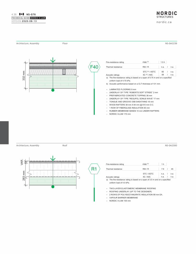
nordic .ca
4.36 NS-GT6 T E C H N I C A L G U I D E N O R D I C X- L A M
VERSION 2020-08-13
DATE
2020-02-01
TITLE
CATEGORY SCALE
Architecture, Assembly 1:10PAGE
DRAWING
Floor NS-DA2239-CA-en
332
mm
F40
DATE
2020-02-01
R1
283
mm
VAR
.
Roof NS-DA2300-CA-enTITLE
CATEGORY SCALE
Architecture, Assembly 1:10PAGE
DRAWING
Architecture, Assembly Floor NS-DA2239
Architecture, Assembly Roof NS-DA2300
Fire-resistance rating FRR (a) 1.5 h F40
Thermal resistance RSI / R n.a. / n.a. NS-DA2239-CA-en
60 / n.a.Acoustic ratings 58 / n.a.
‒ LAMINATED FLOORING 8 mm‒ UNDERLAY OF TYPE “ROBERTS SOFT STRIDE” 2 mm‒ PREFABRICATED CONCRETE TOPPING 38 mm‒ UNDERLAY OF TYPE “REGUPOL SONUS WAVE” 17 mm‒ TONGUE AND GROOVE OSB SHEATHING 18 mm‒ WOOD RAFTERS 38 mm X 64 mm @ 610 mm O.C.‒ 1 ROW OF FIBERGLASS INSULATION 65 mm‒ RUBBER MEMBRANE BANDS 10 mm UNDER RAFTERS‒ NORDIC X-LAM 175 mm
STC (b) / ASTCIIC (b) / AIIC
a) The fire-resistance rating is based on a span of 5.75 m and on a specified uniform load of 4.75 kPa.
b) Acoustic performance based on a CLT thickness of 131 mm.
Fire-resistance rating FRR (a) 1 h R1
Thermal resistance RSI / R 7.9 / 45 NS-DA2300-CA-en
n.a. / n.a.Acoustic ratings n.a. / n.a.
‒ TWO-LAYER ELASTOMERIC MEMBRANE ROOFING‒ ROOFING UNDERLAY (UP TO THE DESIGNER)‒ 2 ROWS OF POLYISOCYANURATE INSULATION 89 mm EA.‒ VAPOUR BARRIER MEMBRANE‒ NORDIC X-LAM 105 mm
STC / ASTCIIC / AIIC
a) The fire-resistance rating is based on a span of 3.5 m and on a specified uniform load of 4.5 kPa.
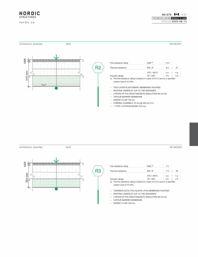
nordic .ca
NS-GT6 4.37T E C H N I C A L G U I D E N O R D I C X- L A M
VERSION 2020-08-13
DATE
2020-02-01
R2
Roof NS-DA2301-CA-enTITLE
CATEGORY SCALE
Architecture, Assembly 1:10PAGE
DRAWING
315
mm
VAR
.
DATE
2020-02-01
R3
Roof NS-DA2302-CA-enTITLE
CATEGORY SCALE
Architecture, Assembly 1:10PAGE
DRAWING
VAR
.28
3 m
m
Architecture, Assembly Roof NS-DA2301
Architecture, Assembly Roof NS-DA2302
Fire-resistance rating FRR (a) 1.5 h R2
Thermal resistance RSI / R 8.2 / 47 NS-DA2301-CA-en
n.a. / n.a.Acoustic ratings n.a. / n.a.
‒ TWO-LAYER ELASTOMERIC MEMBRANE ROOFING‒ ROOFING UNDERLAY (UP TO THE DESIGNER)‒ 2 ROWS OF POLYISOCYANURATE INSULATION 89 mm EA.‒ VAPOUR BARRIER MEMBRANE‒ NORDIC X-LAM 105 mm‒ FURRING CHANNELS 16 mm @ 406 mm O.C.‒ 1 TYPE X GYPSUM BOARD 15.9 mm
STC / ASTCIIC / AIIC
a) The fire-resistance rating is based on a span of 3.5 m and on a specified uniform load of 4.5 kPa.
Fire-resistance rating FRR (a) 1 h R3
Thermal resistance RSI / R 7.9 / 45 NS-DA2302-CA-en
n.a. / n.a.Acoustic ratings n.a. / n.a.
‒ THERMOPLASTIC POLYOLEFIN (TPO) MEMBRANE ROOFING‒ ROOFING UNDERLAY (UP TO THE DESIGNER)‒ 2 ROWS OF POLYISOCYANURATE INSULATION 89 mm EA.‒ VAPOUR BARRIER MEMBRANE‒ NORDIC X-LAM 105 mm
STC / ASTCIIC / AIIC
a) The fire-resistance rating is based on a span of 3.5 m and on a specified uniform load of 4.5 kPa.

nordic .ca
4.38 NS-GT6 T E C H N I C A L G U I D E N O R D I C X- L A M
VERSION 2020-08-13
DATE
2020-02-01
R4
Roof NS-DA2303-CA-enTITLE
CATEGORY SCALE
Architecture, Assembly 1:10PAGE
DRAWING
VAR
.31
5 m
m
DATE
2020-02-01
R5
Roof NS-DA2304-CA-enTITLE
CATEGORY SCALE
Architecture, Assembly 1:10PAGE
DRAWING
VAR
.32
7 m
m
Architecture, Assembly Roof NS-DA2303
Architecture, Assembly Roof NS-DA2304
Fire-resistance rating FRR (a) 1.5 h R4
Thermal resistance RSI / R 8.2 / 47 NS-DA2303-CA-en
n.a. / n.a.Acoustic ratings n.a. / n.a.
‒ THERMOPLASTIC POLYOLEFIN (TPO) MEMBRANE ROOFING‒ ROOFING UNDERLAY (UP TO THE DESIGNER)‒ 2 ROWS OF POLYISOCYANURATE INSULATION 89 mm EA.‒ VAPOUR BARRIER MEMBRANE‒ NORDIC X-LAM 105 mm‒ FURRING CHANNELS 16 mm @ 406 mm O.C.‒ 1 TYPE X GYPSUM BOARD 15.9 mm
STC / ASTCIIC / AIIC
a) The fire-resistance rating is based on a span of 3.5 m and on a specified uniform load of 4.5 kPa.
Fire-resistance rating FRR (a) 1.5 h R5
Thermal resistance RSI / R 7.5 / 43 NS-DA2304-CA-en
n.a. / n.a.Acoustic ratings n.a. / n.a.
‒ TWO-LAYER ELASTOMERIC MEMBRANE ROOFING‒ ROOFING UNDERLAY (UP TO THE DESIGNER)‒ 2 ROWS OF POLYISOCYANURATE INSULATION 76 mm EA.‒ VAPOUR BARRIER MEMBRANE‒ NORDIC X-LAM 175 mm
STC / ASTCIIC / AIIC
a) The fire-resistance rating is based on a span of 5.75 m and on a specified uniform load of 4.75 kPa.

nordic .ca
NS-GT6 4.39T E C H N I C A L G U I D E N O R D I C X- L A M
VERSION 2020-08-13
DATE
2020-02-01
R6
Roof NS-DA2305-CA-enTITLE
CATEGORY SCALE
Architecture, Assembly 1:10PAGE
DRAWING
VAR
.35
9 m
m
DATE
2020-02-01
R7
Roof NS-DA2306-CA-enTITLE
CATEGORY SCALE
Architecture, Assembly 1:10PAGE
DRAWING
VAR
.54
8 m
m
Architecture, Assembly Roof NS-DA2305
Architecture, Assembly Roof NS-DA2306
Fire-resistance rating FRR (a) 2 h R6
Thermal resistance RSI / R 7.7 / 44 NS-DA2305-CA-en
n.a. / n.a.Acoustic ratings n.a. / n.a.
‒ TWO-LAYER ELASTOMERIC MEMBRANE ROOFING‒ ROOFING UNDERLAY (UP TO THE DESIGNER)‒ 2 ROWS OF POLYISOCYANURATE INSULATION 76 mm EA.‒ VAPOUR BARRIER MEMBRANE‒ NORDIC X-LAM 175 mm‒ FURRING CHANNELS 16 mm @ 406 mm O.C.‒ 1 TYPE X GYPSUM BOARD 15.9 mm
STC / ASTCIIC / AIIC
a) The fire-resistance rating is based on a span of 5.75 m and on a specified uniform load of 4.75 kPa.
Fire-resistance rating FRR (a) 2 h R7
Thermal resistance RSI / R 7.7 / 44 NS-DA2306-CA-en
n.a. / n.a.Acoustic ratings n.a. / n.a.
‒ TWO-LAYER ELASTOMERIC MEMBRANE ROOFING‒ ROOFING UNDERLAY (UP TO THE DESIGNER)‒ 2 ROWS OF POLYISOCYANURATE INSULATION 76 mm EA.‒ VAPOUR BARRIER MEMBRANE‒ NORDIC X-LAM 175 mm‒ SUSPENDED CEILING:
‒ METALLIC HANGERS 145 mm‒ CHANNEL IRONS 38 mm @ 1220 mm O.C.‒ FURRING CHANNELS 22 mm @ 406 mm O.C.‒ SOUNDPROOFING MATERIAL 92 mm
‒ 1 TYPE X GYPSUM BOARD 15.9 mm
STC / ASTCIIC / AIIC
a) The fire-resistance rating is based on a span of 5.75 m and on a specified uniform load of 4.75 kPa.
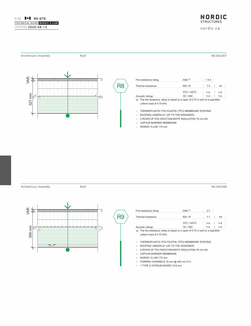
nordic .ca
4.40 NS-GT6 T E C H N I C A L G U I D E N O R D I C X- L A M
VERSION 2020-08-13
DATE
2020-02-01
R8
Roof NS-DA2307-CA-enTITLE
CATEGORY SCALE
Architecture, Assembly 1:10PAGE
DRAWING
VAR
.32
7 m
m
DATE
2020-02-01
R9
Roof NS-DA2308-CA-enTITLE
CATEGORY SCALE
Architecture, Assembly 1:10PAGE
DRAWING
VAR
.35
9 m
m
Architecture, Assembly Roof NS-DA2307
Architecture, Assembly Roof NS-DA2308
Fire-resistance rating FRR (a) 1.5 h R8
Thermal resistance RSI / R 7.5 / 43 NS-DA2307-CA-en
n.a. / n.a.Acoustic ratings n.a. / n.a.
‒ THERMOPLASTIC POLYOLEFIN (TPO) MEMBRANE ROOFING‒ ROOFING UNDERLAY (UP TO THE DESIGNER)‒ 2 ROWS OF POLYISOCYANURATE INSULATION 76 mm EA.‒ VAPOUR BARRIER MEMBRANE‒ NORDIC X-LAM 175 mm
STC / ASTCIIC / AIIC
a) The fire-resistance rating is based on a span of 5.75 m and on a specified uniform load of 4.75 kPa.
Fire-resistance rating FRR (a) 2 h R9
Thermal resistance RSI / R 7.7 / 44 NS-DA2308-CA-en
n.a. / n.a.Acoustic ratings n.a. / n.a.
‒ THERMOPLASTIC POLYOLEFIN (TPO) MEMBRANE ROOFING‒ ROOFING UNDERLAY (UP TO THE DESIGNER)‒ 2 ROWS OF POLYISOCYANURATE INSULATION 76 mm EA.‒ VAPOUR BARRIER MEMBRANE‒ NORDIC X-LAM 175 mm‒ FURRING CHANNELS 16 mm @ 406 mm O.C.‒ 1 TYPE X GYPSUM BOARD 15.9 mm
STC / ASTCIIC / AIIC
a) The fire-resistance rating is based on a span of 5.75 m and on a specified uniform load of 4.75 kPa.

VERSION2020-08-13
5
T ECHNIC A L GU IDENOR DIC X-L A M
NS-GT6ENGLISH
ADDITIONAL INFORMATION
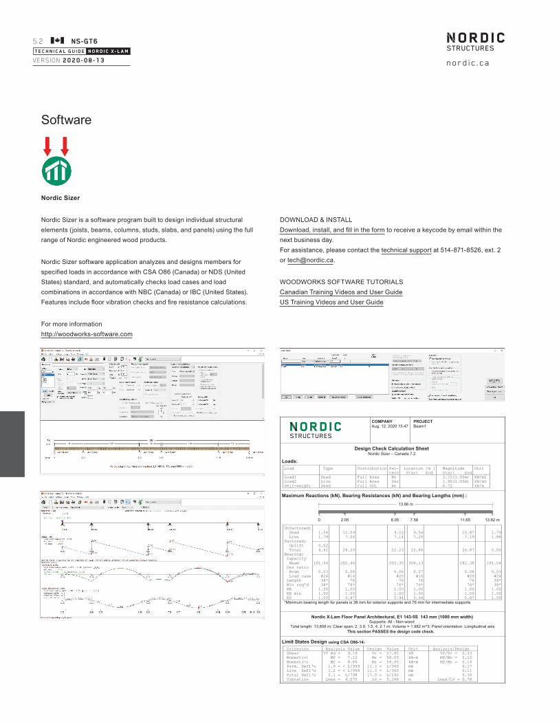
nordic .ca
COMPANYAug. 12, 2020 15:47
PROJECTBeam1
Design Check Calculation Sheet Nordic Sizer – Canada 7.2
Loads:Load Type Distribution Pat- Location [m ] Magnitude Unit tern Start End Start EndLoad1 Dead Full Area No 2.72(1.00m) kN/m2 Load2 Live Full Area Yes 1.90(1.00m) kN/m2 Self-weight Dead Full UDL No 0.72 kN/m
Maximum Reactions (kN), Bearing Resistances (kN) and Bearing Lengths (mm) :
2.05 6.05 7.58 11.65
13.86 m
13.82 m0
Unfactored: Dead 1.54 12.59 9.22 9.56 12.87 1.79 Live 1.79 7.04 7.14 7.28 7.19 1.88 Factored: Uplift 0.02 Total 4.61 26.29 22.23 22.86 26.87 5.06 Bearing: Capacity Beam 161.54 282.46 305.35 304.13 282.38 161.54 Des ratio Beam 0.03 0.08 0.06 0.07 0.08 0.03 Load case #24 #14 #25 #16 #29 #24 Length 38* 76 76 76 76 38* Min req'd 38* 76* 76* 76* 76* 38* KB 1.00 1.00 1.00 1.00 1.00 1.00 KB min 1.00 1.00 1.00 1.00 1.00 1.00 KD 1.00 0.87 0.94 0.94 0.87 1.00*Minimum bearing length for panels is 38 mm for exterior supports and 76 mm for intermediate supports
Nordic X-Lam Floor Panel Architectural, E1 143-5S 143 mm (1000 mm width) Supports: All - Non-wood
Total length: 13.858 m; Clear span: 2, 3.9, 1.5, 4, 2.1 m; Volume = 1.982 m^3; Panel orientation: Longitudinal axisThis section PASSES the design code check.
Limit States Design using CSA O86-14: Criterion Analysis Value Design Value Unit Analysis/Design Shear Vf @d = 9.19 Vr = 27.95 kN Vf/Vr = 0.33 Moment(+) Mf = 7.12 Mr = 58.05 kN-m Mf/Mr = 0.12 Moment(-) Mf = 8.86 Mr = 56.95 kN-m Mf/Mr = 0.16 Perm. Defl'n 1.9 = < L/999 11.3 = L/360 mm 0.17 Live Defl'n 1.2 = < L/999 11.3 = L/360 mm 0.11 Total Defl'n 5.1 = L/798 17.0 = L/240 mm 0.30 Vibration Lmax = 4.070 Lv = 5.186 m Lmax/Lv = 0.78
5.2 NS-GT6 T E C H N I C A L G U I D E N O R D I C X- L A M
VERSION 2020-08-13
Software
Nordic Sizer
Nordic Sizer is a software program built to design individual structural elements (joists, beams, columns, studs, slabs, and panels) using the full range of Nordic engineered wood products.
Nordic Sizer software application analyzes and designs members for specified loads in accordance with CSA O86 (Canada) or NDS (United States) standard, and automatically checks load cases and load combinations in accordance with NBC (Canada) or IBC (United States). Features include floor vibration checks and fire resistance calculations.
For more information http://woodworks-software.com
DOWNLOAD & INSTALL Download, install, and fill in the form to receive a keycode by email within the next business day. For assistance, please contact the technical support at 514-871-8526, ext. 2 or [email protected].
WOODWORKS SOFTWARE TUTORIALS Canadian Training Videos and User Guide US Training Videos and User Guide


nordic .ca
maintenance guide >GE2
installation guide >GI2
structural details >DS2
architectural details >DA2
product warranty >N-X601