m o u n t a i n e s a t e - stonehurst...
TRANSCRIPT

M O U N T A I N E S A T E
URBAN DESIGN ARCHITECTURAL & LANDSCAPING CONTROLS
JULY 2012
REV 15
CONTENTS
VISION 5
1. INTRODUCTION 5
2. DEFINITIONS 6
STONEHURST MOUNTAIN ESTATE – Specification List 11
3. BUILT FORM 16
4. GENERAL BUILDING FORM CONTROL 17
5. ROOFS 33
5.1 General 33
5.2 Permissible Major Roof Forms: 33
5.4 Garage Roofs 34
5.5 Gables & Eaves 34
5.6 Roof Lights and Roof Windows 34
5.7 Roof Materials & Colour 34
5.8 Roofs 35
6. WALL CONSTRUCTION AND FINISHES 35
7. WINDOW TYPES AND FINISHES 36
8. DOOR TYPES AND FINISHES 36
9. SHUTTERS 36
10. BURGLAR BARS 37
11. EXTERNAL BUILT ELEMENTS 37
11.1 Perimeter Fences and Boundary Walls: 37
11.1.5 Drying Yard Walls (Refer to Item 11.1.2) 38
11.1.6 Screening/ Privacy Walls (No reference in the Design Manual) 38
11.1.7 Heights: 38
11.1.8 Boundary Walling / Retaining Combinations. 38
11.2 Visually Permeable Fencing 40
11.3 Palisade Fencing: 40
11.4 Visually Permeable Fencing: 41
11.5 Retaining Walls, Steps and Ramps 41
11.6 Building Platforms 42
11.7 Retaining Walling 43
11.8 Verandahs & Pergolas 44
11.9 Timber Decks 44
11.10 Balconies 44
11.11 Balustrading 45

Page 3 of 73
12. EXTERNAL WORKS 46
12.1 Waste Pipes 46
12.1.2 Rainwater Goods 46
12.2 Storm Water/ Drainage 46
12.2.4 Storm Water Channels 46
12.3 External/ Outdoor Lighting 46
12.3.5 External Lighting: 47
12.4 Signage, Lettering And Numbering 48
12.5 Swimming Pools and Water Features 48
12.5.4 Pool safety- Water features ponds fountains etc . 48
12.6 Outbuildings, Carports and other Secondary Elements 48
12.6.3 Second Dwellings 49
12.7 Laundry and Refuse Areas 49
12.8 Other Services 49
12.8.3 Solar Heating 49
12.8.4 Generators – Noise limitations 50
13. ACCESS 50
13.1 Vehicular Access/ Driveways 50
14. HARD SURFACING MATERIALS 50
15. ENVIRONMENTAL/ SOFT LANDSCAPING CONTROLS 51
15.1 Site Clearing 51
15.2 Planting Character 52
15.2.8 Landscaping requirements - Trees . 52
15.3 Sidewalk/ Roadside Planting 53
LANDSCAPING AMENDMENT 53
15.4 Plant List 54
15.4.1 Shrubs 54
15.4.2 Groundcovers 55
15.4.3 Bulbs 55
15.4.4 Wetland/ water plants 55
15.4.5 Tree Species 56
15.4.6 Climbing plants 56
15.4.7 Hedge species 56
16. FIRE PRECAUTIONS 57
16.8 Fire Safety- Spark Control 57
17. ARCHITECTURAL & LANDSCAPE REVIEW AND PLAN SUBMISSION PROCESS 58
17.6 Submission to Design Review Committee 58
17.6.6 Information required on all plans. 59
17.6.7 REQUIREMENTS FOR A LANDSCAPE PLAN SUBMISSION: 59
PLAN SUBMISSION MUST INCLUDE: 59
17.7 Submission of Council Drawings to SHOA 60
17.8 Local Authority Plan Approval 61
18. DISCLAIMERS 61

Page 4 of 73
Specification List: March 2006 62
ANNEXURE 1: GROUP HOUSING SITES AT STONEHURST ESTATE 63
1. INTRODUCTION 63
2. BUILT FORM 63
3. GENERAL BUILDING FORM CONTROL 64
3.1 Coverage 64
3.2 Building Lines 64
3.3 Height Restrictions 65
3.4 Roofs 65
GENERAL BUILDING FORM CONTROLS: STONEHURST CLOSE:
GENERAL BUILDING FORM CONTROLS: STONEVILLAGE:
ADDENDUM 1: SOLAR PANELS: 70
ADDENDUM 2: SUSTAINABLE DESIGN: 70
Page 5 of 73
VISION
The Stonehurst Mountain Estate is set against the slopes of Silvermine Mountain, forming a unique
Mountain setting for the residential development. The uppermost parts of the site form a significant
part of the view from the valley below, whilst the view of the lower slopes is screened by the Golf
Course and existing trees.
The dwellings for the Stonehurst Mountain Estate should be designed and positioned in such a way
that they would form an integral part of the natural landscape. This will be promoted by the use of
natural materials such as stone and timber in dark and neutral tones, which blend into the
environment. The dwellings should be structured to define courtyards or garden spaces which will
create a sheltered external space, whilst optimizing the views over the valley and the Constantia
Berg to the Northwest of the site. Owners should cooperate during the design process to allow the
optimization of views within the Estate.
This manual is aimed at encouraging a modern interpretation of openings, which could open up to
integrate the internal spaces with the exterior courtyard or garden. It does not intend to be
prescriptive in terms of architectural style, but rather to allow flexibility for individual expression.
Revivalist or Period Architectural Styles are not permitted, while a modern/ contemporary language
is seen as desirable.
The landscape architectural design shall form an integral part of the architectural design process
and shall not be seen as an “add-on” once the building is complete. Gardens, courtyards, avenues,
water features, terraces, pools, pergolas and fences shall be used to enrich and complement the
interior spaces and shall inform the architectural design process and vice versa. The design of
external spaces and the link between the land, water and built forms is seen as integral to the
character and aesthetic success of the Estate as a whole.
The architectural and landscaping for the Stonehurst Mountain Estate should therefore result in a
development, which is sympathetic to the mountain’s topography, creating building footprints and
roof forms, which relate to the natural contours of the site. A number of different roof forms will be
allowed to assist in delivering fragmented and varied roof scapes separated by flat roof sections
and augmented by pergolas and verandahs to minimize the impact of individual buildings against
the slope of the mountain.
1. INTRODUCTION
1.1 This document sets out the Urban Design, Architectural and Landscape Controls with which
the Home Owners will have to comply, and forms part of the Stonehurst Homeowners
Association (SHOA) Constitution.
1.2 In terms of the Agreement of Sale and the Constitution, Owners will be obliged to submit their
drawings (including Landscape plan) to the Design Review Committee (appointed by the
SHOA) for design approval, before submitting them to the local authority for final approval.
Approval or rejection of the design is entirely at the discretion of the Design Review
Committee. Refer to the requirements for submissions at the end of this document.
Page 6 of 73
1.3 The SHOA has the right to vary the requirements contained within this document subject to the
approval of the Municipality.
1.4 The Owner and his Contractor will be subject to the provisions of an Environmental Contract
which will be administered by the SHOA and which will contain obligations and penalties for
any breach of contract.
1.5 In these guidelines the words “must or “shall” indicate mandatory provisions, while the word
“should” indicates desirable and recommended provisions that may only be deviated from at
the Sole discretion of the Design Review Committee.
2. DEFINITIONS
2.1 Design Review Committee (DRC)
Means the committee formed by the Urban Design & Architectural & Landscape
practice and the SHOA representative. The role of the committee is to review and
approve all design proposals, prior to submission to City of Cape Town.
2.2 Urban & Architectural Design Controls (UAC)
Means the legal document to control the nature and aesthetics of development, and
to ensure the protection, improvement and enhancement of the natural environment.
2.3 Balcony
A floor projecting outside a building at a level higher than ground floor level, enclosed
only by low walls or railings or by the walls of adjacent rooms, and includes a roof, if
any, over such floor or any pillars supporting the roof.
2.4 Basement
Any portion of a dwelling generally below natural ground level. No portion of a
basement (measured to be finished floor level above the basement) may project more
than 1,0m above natural ground level. A basement level is not considered as a building
storey for the purposes of height restrictions, but is included in the calculation of
physical height above natural ground level where applicable.
2.5 Coverage
In relation to a dwelling house, coverage means the maximum area covered by any
floor of the dwelling (whether or not useable), as measured from the outer face of the
exterior walls or similar supports of such a dwelling, provided that:
i. Where the dwelling consists of more than one storey, total coverage shall be the
maximum extent of the floor space of all storeys, but not the sum of all floors. (refer
to 2.19)
ii. For the purposes of measuring maximum coverage; garages, storage, boat houses
or other free-standing enclosed structures shall be included. Any covered spaces,
such as overhanging balconies and verandahs shall also be included.
Page 7 of 73
2.6 Deck
A timber external floor area, which is raised off the ground level on posts and projects
out beyond the building perimeter and includes any railing enclosing it. The posts must
be a max. of 1.2m above natural ground. It does not refer to balconies at the first floor
level of a dwelling. If a deck is built on a solid base, restrictions applicable to verandahs
apply.
2.7 Site (Construction Phase) Environmental Management Plan (SEMP)
Describes how controls are to be carried out on site and describes mitigation measures
in detail, and is prescriptive, identifying specific individuals or organizations responsible
for undertaking specific tasks to ensure that impacts on the environment are minimized
during construction.
2.8 Estate Architects (EA)
Means the selected Architectural and Landscape practice that will form part of the
Design Review Committee (DRC).
2.9 Finished Floor Level (FFL)
Maximum final level of floor finishes. For the purpose of height restriction calculations,
the “worst” or highest point is used. Where FFL is stepped, height restrictions above
natural ground level must be met for each individual platform or level.
2.10 Finished Ground Level (FGL)
Refers to the final surface level after construction and landscaping, and could be hard
landscaped surface level or soil level. (Refer to 2.16)
2.11 Garage
A building used for the housing of motor vehicles or boats, and not a “habitable” room.
2.12 Garden Terrace
A level or platform created through either cutting or fill, which is not directly attached
to the main building elements. Garden terraces refer to areas surfaced with hard or soft
landscaping.
2.13 Site Diagrams
Means the diagram of any specific individual site, describing the site boundaries,
building lines, and any other restrictions imposed on the site. The information on the
diagram will be legally binding.
2.14 Major Plan forms
Refer to the main building elements attached to the main building forms and include
linking elements between major plan forms, balconies, pergolas, and enclosure of desk
or verandahs.
2.15 Minor Plan Forms
Refer to building elements attached to the main building forms and include linking
elements between major plan forms, balconies, pergolas, and enclosure of decks or
verandahs.

Page 8 of 73
2.16 Natural Ground Level (NGL)
Means the ground level as at the date of transfer to the original purchaser. Preliminary
surveyed contours of each site will be provided with each site diagram, and will serve
as a guide. Each site is to be surveyed in detail prior to commencement of earth works.
The detail survey is to be attached to building plans submission to the DRC, and will
generally serve as the base information measuring height above natural ground level.
2.17 Overlooking Feature
Refer to features (excluding ground floor areas) allowing views over the adjoining
residential properties, and include first floor window, balconies and terraces. Council
regulations apply.
2.18 Terrace
A floor area created on a flat roof over a portion of a storey of a building resulting from
the setting back of a portion of the building above such a storey.
2.19 Floor Space
i. Floor space in relation to a dwelling house means the area of every floor of the
dwelling as measured from the inner face of the exterior walls or similar supports of
such dwelling. When the dwelling consists of more than one storey, the total floor
space shall be the sum of the floor space of all the storeys.
ii. For the purpose of measuring maximum floor space, garages, outbuilding and
covered balconies, terraces, patios and verandahs shall be included.
2.20 Portion Boundaries
i. Street Boundary The boundary of a residential portion, which abuts any street, or a
portion of the street.
ii. Side (common) Boundary The boundary of a residential portion, which abuts
another portion, and is adjacent to the street boundary.
iii. Rear (common) Boundary The boundary of a residential portion, which abuts
another portion, but is not adjacent to the street boundary.
2.21 Double Storey
i. A double storey will be defined as any floor above the ground floor, which has a
floor to wall plate height greater than 1.5m.
ii. The height of the double storey dwelling, including the roof, is restricted to 8.5m
above the natural ground level of the site. No portion of the building, except
chimney, shall be higher than 8.5m above any point of the natural ground level
immediately below it.
iii. No vertical face of the building shall be higher than 7.0m measured externally from
finished ground level to wallplate or eaves level. A different condition applies to a
monopitch roof on street (see 5.2.2)

Page 9 of 73
SECOND DRAFT AMENDMENT: 2008/06/17
2.22 Max 2 Storey Limitation
A Maximum of 2 storeys may be built using the following as a guide. A Basement is not
considered a storey, provided it conforms to the City Council and Architectural Design
Manual basement definition. Non-habitable space such as stairs, stores and passages may
overlap in section by not more than 2m (provided in doing so it is not circumventing this
control. All the other parameters must still be met such as Height above NGL, stepping of the
façade, Max façade height 7m (a minimum step or min architectural element should be
2m).
2.23 Façade Fragmentation
In reference to the façade fragmentation, this must be more than a wall thickness (in order to
create shade and fragmentation) A room width should be used as the division minimum. As
the min SABS room size is 2m, the step size or Fragmenting element (pergola/ balcony etc.)
must be a minimum of 2m.
2.24 Façade Height Clause 2.21 (iii)
(Max upper storey of 15m Clause 3.4
Where the manual calls for fragmentation the building will be required to step by a min of 2m
in plan or section, provided in doing so it creates fragmentation, shadow to break the
massing in such a way as to minimize the visual impact.
THIRD DRAFT AMENDMENT: 2009/07/30
2.25 Double Dwellings - Further Aesthetic Interpretation
Double dwellings, garages, servants quarters or similar such ‘stand-alone’ structures need to be
attached by significant building elements such as a wall or roofed element, or both. Transparent
elements such as pergolas or paved walkways are considered to be insufficient. Please refer to
diagram 1a below.
Diagram 1a
AMENDMENT : 2012/05/23
2.26 Residents Parking Bays
This is to be either a double garage, two single garages, a combination of parking bay and garage
to accommodate 2 vehicles in total, or two parking bays. This is to be provided in addition to the
requirement for visitors parking.
Page 10 of 73
ANNEXURE 1
MOUNTAIN ESTATE
Page 11 of 73
SPECIFICATION LIST
STONEHURST MOUNTAIN ESTATE – Specification List
Roof Materials (Refer to list in Urban Design and Architectural Controls Document)
a) Natural Slate – Colour: Silver Blue
b) Corrugated Sheeting: Kliplok or Victorian Profile – Colour: Charcoal; Dark Dolphin
SECOND DRAFT AMENDMENT: 2008/06/17
Roofing
Silver Blue Slate Masista or equal
Multi Colour Slate Masista
(Silver Blue 80%- West Country & Bright Brown 20%)
Note: to be all from the same quarry.
Wall Finishes (Refer to no. 6 in Urban Design and Architectural Controls document)
i. “Shiplapped” Hardwood Boarding – Building Planks: Everite
ii. Natural Stone: – Table Mountain Light Almond Sandstone / Stone shape
horizontally elongated
iii. Plastered walls – paint colors:
Natural colors – Dulux
i. Kid Gloves 6J1-2
ii. New Fallen Snow 6J1-3
iii. Birch Bark Canoe 6J1-4
iv. Pacific Bungalow 6J1-5
Marmoran /Permacrete 1.5 mm Random Pattern

Page 12 of 73
SECOND DRAFT AMENDMENT: 2008/06/17
Building Colours:
In order to expand the possible colours from the approved colours the following are
approved colours. No other colours will be considered.
Dulux
Birch Bark Canoe 6j1-4
Kid Gloves 6j1-2
New Fallen Snow 6j1-3
Pacific Bungalow 6j1-5
Plascon
French Chateau 6j1-6
Safari Tan d13-4
River Rock 6j1-7
Chaps y1-e2-1
Beach Wood y3-d2-1
Cigar Smoke pal 88
Maison Blanche Y1-E2-1
Midas Earthcote
Stonehenge MTO748
Papyrus MB1626
THIRD DRAFT AMENDMENT: 2009/07/30
Building Colours
In order to expand the approved colour range the following additional paint colours
have been approved. No other colours will be considered.
Dulux
Birch Bark Canoe 6j1-4
Kid Gloves 6j1-2
New Fallen Snow 6j1-3
Pacific Bungalow 6j1-5
Dulux - 2009 - Additional colours:
White 7 00YY65/060
White 7 10YY41/083
White 7 10YY48/071 Rum Caramel 4
White 7 20YY43/083
White 7 20YY51/098
White 7 30YY51/098 Toasty Grey
White 7 90YR55/051 Natural Taupe 2
Page 13 of 73
Plascon
French Chateau 6j1-6
Safari Tan d13-4
River Rock 6j1-7
Chaps y1-e2-1
Beach Wood y3-d2-1
Cigar Smoke pal 88
Maison Blanche Y1-E2-1
Plascon - 2009 addition - Additional colours
Chaps Expressions D13-3
Safari tan Expressions D13-4
Trade Winds Expressions D13-5
Winter Savanna Inspirations NEU01
River Clay Inspirations NEU10
Statued Inspirations NEU12
Veldrift Plascon Inspired Y2-D2-3
Maison Blanche Plascon Inspired Y1-E2-1
Stonewash Plascon Inspired Y2-D2-2
Country Mushroom Y1-D2-2
Baby Elephant Y1-E1-4
Midas Earthcote
Stonehenge MTO748
Papyrus MB1626
In addition, kindly note:
Only the above stipulated colours will be acceptable.
Only a matt paint finish will be accepted. No glossy finishes will be permitted.
Textured paints will be permitted on approval from the design review
committee.
Timber cladding – Balau stained and oiled
FIRST DRAFT AMENDMENT: 2006/12/05
Specification Inclusions:
Stone Cladding to be used for the project is Table Mountain Light Almond Sand
Stone.

Page 14 of 73
SECOND DRAFT AMENDMENT: 2008/06/17
Specification Inclusions/Exclusions
Walling:
Inclusions:
Brick Clay or cement Bricks
Timber cladding (max area 30%)
Sand stone cladding
Exclusions:
Styrox
Dry exterior drywalling
Sheet metal cladding
Everite cladding
Fake Imitation stone
Log Cabins
Cob / mud Housing
DRAFT AMENDMENT: 2012/05/25
Consideration should be given to the type of material used in the construction of dwellings
with respect to environmentally friendly materials.
Locally sourced materials should be used where possible to minimise the embodied energy
Avoid materials that release toxic compounds and irritants. Paint & plaster finishes should
have low VOC, Particle board, carpet, glue low VOC, high % recycled fibre.
Timber materials should be Certified timber, bamboo, fast growing softwood composites
where possible
Windows, Doors & Shutters
(Refer to no. in Urban Design and Architectural Controls document)
a) Natural Timber:
Teak Stain Ebony Stain
b) Epoxy Coated Aluminium:
Manufacturer: InterponD 25
ANP 3055: Matt Charcoal
ANP 3057: Matt Dark Amber Grey
ANP 37030: Matt Stone Grey
ANP 39007: Matt Grey Aluminium
c) Anodised Aluminium:
Natural Finish

Page 15 of 73
Verandas & Pergolas (Refer to Development Controls)
a) Verandas and pergolas to match colour and materials of windows, doors and
shutters
i. Natural untreated timber such as balau will also be permitted
2.1 Single Storey
i. The height of the single storey dwelling, including the roof, is restricted to
6.5m above the natural ground level of the site. No portion of the building,
except chimneys, shall be higher than 6.5m above any point of the natural
ground level immediately below it.
ii. No vertical face of the building shall be higher than 4.5m measured
externally from finished ground level to wallplate or eaves level.
2.2 Sites A
(Refer to the Development Controls: Summary ref: 05.1292/av10 dated 28
March 2006)
i. Sites A represent the erven with general restrictions, and includes portion
development control summaries: 24 - 30; 33 – 38 (see special height
restriction under 4.1.3); 47, 48; 54 - 67; 87 - 118; 119 - 124; 128 - 130; 132 - 133;
135 - 140; 147; 155 - 167; 170, 171; 173 - 179
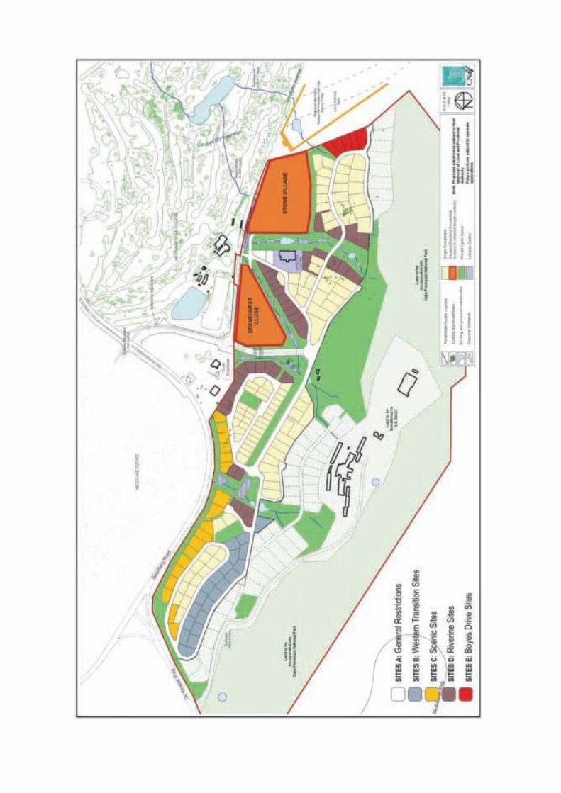
2.3 Sites B
(Refer to the Development Controls: Summary ref: 05.1292/av10 dated 28
March 2006)
i. Sites B represent the erven that have been identified as the Western
Transition Sites, and include portion numbers 1,3 to 6,8 to 23.
2.4 Sites C
(Refer to the Development Controls: Summary ref: 05.1292/av10 dated 28
March 2006)
i. Sites C represent the erven that have been identified as the Scenic Sites,
and includes portion numbers 12,13,31,32,39- 46,49,50,70-75.
2.5 Sites D
(Refer to the Development Controls: Summary ref: 05.1292/av10 dated 28
March 2006)
i. Sites D represent the erven that have been identified as the Riverine Sites,
and includes portion numbers 51,52,53,68,69,70,76-80,81-
86,125,127,131,134,141 151,152,153,154,168,169,172.

Page 16 of 73
2.6 Sites E
(Refer to the Development Controls: Summary ref: 05.1292/av10 dated 28
March 2006)
i. Sites E represent the erven that have been identified as the Boyes Drive Sites,
and includes numbers 180-184
Sites F
(Refer to the Development Controls)
i. Sites F represent the erven that have been identified as the Mountain Sites,
(precincts 1, 2 & 3) and includes numbers 185-197,199-200,203- 207, 211-
216.
Sites G
(Refer to the Development Controls)
i. Sites G represent the erven that have been identified as the Mountain
Stream Sites, that abut the riverine areas (precincts 2 & 3) and includes
numbers 198, 201, 202, 208 - 210 & 217.
Specification List
Means the list of specifications that would be permitted at Stonehurst Estate.
The specification list will contain all roof finishes, window, door and shutter
materials, wall finishes and materials allowed on pergolas, verandahs and
balconies. (See Annexure 1)
3. FORM
3.1 The designer should aim to position the house forms in such a way that it
could create a sheltered garden or courtyard space which is protected from
the South-Easter and which optimizes the views to the North and North-West.
3.2 The plan forms used should be small and fragmented as opposed to large
and monolithic, so that the shadows cast by the many planes minimize the
visual impact of the dwelling on the mountain slope.
3.3 House forms are to be composed of major and minor rectilinear forms:
Major forms with double pitched or mono pitched roofs are limited to a
maximum width of 7m and minimum of 4.0m width measured externally (see
diagram 1). Minor forms consist of elements like verandahs, pergolas, concrete
roofs and lean-to’s.

Page 17 of 73
3.4 The building proportion (width to length) to be at least 2:3. The length of the
building can extend beyond this, but is restricted to a maximum length of 15m
for all upper floors of double storeys.
3.5 Major roof forms must be parallel or perpendicular to the other major forms.
These rectangular forms may be offset at any angle relative to the boundary
line. If the dwelling consists of more than two major forms, one of these forms
must be parallel or perpendicular to a specific boundary line, even if it is not
parallel or perpendicular to the other major forms. It is encouraged that major
forms follow the contours of the site.
3.6 The use of projecting decks, verandahs and eaves to shade walls and areas
of glass and thereby break up the visual impact of the building, is encouraged.
Verandahs and lean-to’s shall not be more than two-thirds of the width of the
major form to which it is attached.
DIAGRAM 1:
HOUSE
FORMS
4. GENERAL BUILDING FORM CONTROL
Four residential areas have been identified within the Stonehurst Mountain Estate, and
due to the location and visibility of these dwellings, differences in urban design controls
have been employed for each area. The areas are Sites B (Western Transition Sites), Sites
C (Scenic Sites), Sites D (Riverine Sites) and Sites E (Boyes Drive Sites). General restrictions
(Sites A) apply to all the other sites, which are not included in the four residential areas.
What follows is a description for the building form controls for Sites A, and a summary of
the area specific building form controls for the various areas. Please note that the
Development Controls: Summary (ref: 05.1292/av10 dated 28 March 2006) attached,
illustrate the various areas. (See Relevant Annexure 2)
ANNEXURE 2
MOUNTAIN ESTATE
DEVELOPMENT CONTROLS: SUMMARY

Page 20 of 73
4.1 Sites A
These are sites which are controlled by the general development controls /
restrictions and are not subject to the more restrictive controls that apply to
Sites B, C, D and E (see 2.23 above).
4.1.1 Coverage
Coverage refers to all the buildings and includes the main dwellings, garages,
verandahs and balconies within the prescribed area.
4.1.1.1 Sites measured less than 1000m2
are restricted to a maximum
coverage of 40%, unless more restrictive conditions apply.
4.1.1.2 Sites that are larger than 1000m2 are to have a maximum
coverage of 500m2, unless more restrictive conditions apply.
4.1.2 Building Lines
4.1.2.1 The building lines for each site will be indicated on the individual
site diagrams. Please note that building service servitudes will
override building lines.
4.1.2.2 The general sites are those sites where no specific restrictions have
been incurred.
4.1.2.3 In general the building lines should conform to the following
restrictions:
i. Street building lines:
Main building : 3.0m
Garages : 1.5m
ii. Common / Side Boundary lines:
Main building : 6.0m aggregate with a minimum of 2.0m on one side
Garages : Zero metres
Common / Rear building lines:
Main buildings : 3.0m
Swimming pools : 1.0m
Retaining walls : zero metre
These setbacks shall apply to all Single Residential Erven, except more onerous controls
have been applied to areas identified as Sites B, C, D and E.

Page 21 of 73
4.1.3 Height restrictions
4.1.3.1 Double and single storeys will be allowed in Stonehurst Mountain Estate.
The following restrictions should be employed:
iii. The height of the dwellings on Sites A, including the roof, is restricted to 8.5m
above the natural ground level of the site. No portion of the building, except
chimneys, shall be higher than 8.5m above any point of the natural ground
level immediately below it.
iv. Sites 24 – 30; and 33 – 38 is restricted to 8.0 m above the natural ground level
of the site.
v. No external wall of any dwelling to have a vertical plane of more than 7.0m
measured externally from finished ground level to wall plate or eaves level.
DIAGRAM 2: DOUBLE STOREY RESTRICTIONS
The natural ground level will be as surveyed and issued by the Developer on
registration of transfer of the portion. These details are to be submitted to the
Director: Planning & Development for approval prior to transfer clearance of
any portion, within the relevant phase, being issued. The survey is to indicate
1m intervals for the buildable area of each portion number.
4.1.4 Parking
Provision must be made for two visitor-parking bays on each site in addition to
the residents parking (not applicable to the Grouped Residential sites:
Stonehurst Close and Stone Village).
4.2 Sites B
These sites are located in the Western Transition Zone area (see 2.24 above).
4.2.1 Coverage
4.2.1.1 Site B is limited to a maximum floor space of 400m2. This
includes all garages, outbuildings and covered balconies,
decks terraces, patios and verandahs.

Page 22 of 73
4.2.2 Building Lines
4.2.2.1 The building lines for each site will be indicated on the
individual site diagrams.
4.2.2.2 An aggregate side building space of 9m must be
created, with the setback on one side measuring at least
3.0m.
4.2.2.3 Please note that building service servitudes will override
building lines.
4.2.2.4 In general the building lines will conform to the following
restrictions:
i. Street Boundary:
Main building & garages :3.0m
ii. Side (common) Boundary:
All building components (including garages):
9.0m aggregate with a minimum of 3.0m on one
side of the building
iii. Rear (common) Boundary:
Main building (including minor building forms) :
6.0m
4.2.3 Height Restrictions
4.2.3.1 The height of all structures is limited to a maximum of
6.5m from natural ground level. No portion of the structure,
except chimneys, shall be higher than this height above the
point of the natural ground level immediately below it.
DIAGRAM 3: SINGLE STOREY RESTRICTIONS
4.2.4 Fencing
4.2.4.1 Visually permeable fencing must be installed on the
natural interface / urban edge side of the property.

Page 23 of 73
SECOND DRAFT AMENDMENT: 2008/06/17
4.3 Sites B: Further interpretation on Area of floor space.
If we look at the intent to limit built fabric of the control document Definition, it
lists in its limitation of Floor space Built structures:
Garages.
Outbuildings
Covered balconies definition (2.3)
Covered terraces definition (2.18)
Covered verandah’s. CCC zoning scheme definition
Covered decks ( item 4.2.1) definition (2.6)
Covered patios ( item 4.2.1)
Uncovered surfacing is not included in the calculation. Driveways and yard
areas are not included in this limitation.
The paving materials of these surfaces must be approved exterior finished as
per the Design Manual.
4.4 Sites C
These sites are located adjacent to the scenic routes of the area, namely Ou
Kaapse Weg and Steenberg Road (see relevant clause above).
4.4.1 Coverage
4.4.1.1 Coverage refers to all the buildings and includes the
main dwellings, garages, verandahs and balconies within
the prescribed area.
4.4.1.2 Sites measured less than 1000m2 are restricted to a
maximum coverage of 40%, unless more restrictive
conditions apply.
4.4.1.3 Sites larger than 1000m2 are to have a maximum of
500m2, unless more restrictive conditions apply.
4.4.2 Building Lines
4.4.2.1 The building lines for each site will be indicated on the
individual site diagrams.
4.4.2.2 On extreme sloping sites identified on the Site
Development Plan, garages may be placed 1.5m from the
street boundary.
4.4.2.3 Please note that building lines will conform to the
following lines.

Page 24 of 73
4.4.2.4 In general the building lines will conform to the following
restrictions:
iv. Street boundary:
Main building & garages 3.0m
v. Side (common) boundary:
Main building & garages:
6.0m aggregate with a minimum of 2m on one side
of the building
vi. Rear (common) boundary:
Main building (including minor forms) : 6.0m
vii. Boundaries facing onto scenic routes:
Main building and garages
10.0m
4.4.3 Height Restrictions
4.4.3.1 The height of all structures is limited to a minimum of 6.5m
from natural ground level. No portion of the structure,
except chimneys, shall be higher than this height above the
point of the natural ground level immediately below it.
4.4.4 Fencing
4.4.4.1 Visually permeable fencing must be installed on the
scenic route side of the property.
4.5 Sites D
These sites all border onto riverine corridors (see 2.26 above).
4.5.1 Coverage
4.5.1.1 Coverage refers to all the buildings and includes the
main dwellings, garages, verandahs and balconies within
the prescribed area.
4.5.1.2 Sites measured less than 1000m2 are restricted to a
maximum coverage of 40%, unless more restrictive
conditions apply.
4.5.1.3 Sites larger than 1000m2 are to have a maximum
coverage of 500m2, unless more restrictive conditions apply.

Page 25 of 73
4.5.2 Building Lines
4.5.2.1 The building lines for each site will be indicated on the
individual site diagrams.
4.5.2.2 On extreme sloping sites identified on the Site
Development Plan, garages may be placed 1.5m from the
street boundary to the approval of the Design Review
Committee.
4.5.2.3 Please note that building service servitudes will override
building lines.
4.5.2.4 In general the building lines will conform to the following
restrictions:
i. Street boundary:
Main building & garages : 3.0m
ii. Side (common) Boundary:
Main building:
6.0m aggregate with a minimum of 2m on one side
of the building
iii. Garages:
0.0m, provided that no windows or any overlooking
features occur on this boundary.
iv. Rear (common) boundary:
Main building (including minor building forms) :
6.0m
4.5.3 Height Restrictions
4.5.3.1 The height of all structures is limited to a maximum of
8.5m from natural ground level. No portion of the structure,
except chimneys, shall be higher than this height above the
point of the natural ground level immediately below it.
FIRST DRAFT AMENDMENT: 2006/12/05/12
4.5.4 Environmental - Riverine Buffer Widths
All homes in the Riverine Sites D are required to submit a Site
Environmental Mgt Plan in respect of their plan submission process to
the local authority’s Environmental Officer for approval.
No hard structures (ie no paving, no loose flagstones and no walls are
to be constructed in the riverine buffer width)
Palisade fencing (permeable fencing in the riverine buffer area will
consist of “cemented in “fencing posts only.

Page 26 of 73
Solid walling may not be built within this 5m building zone, only visually
permeable fencing and palisading. Retaining Gabions may be
considered upon each applications merits and location.
4.6 Sites E
These sites in the east of the Estate overlook Boyes Drive (see 2.27 above).
4.6.1 Coverage
4.6.1.1 Sites E are limited to a maximum floor space of 400m2.
This includes all garages, outbuildings, covered balconies,
decks terraces, patios and verandahs.
4.6.2 Building Lines
4.6.2.1 The building lines for each site will be indicated on the
individual site diagrams. Specific building lines have also
been determined to define the urban edge and to preserve
certain open spaces. These building lines will be indicated
on the overall layout plan.
4.6.2.2 On extreme sloping sites identifies on the Site
Development Plan, garages may be placed 1.5m from the
street boundary.
4.6.2.3 Please note that building service servitudes will override
building lines.
4.6.2.4 In general the building lines will conform to the following
restrictions:
i. Street Boundary:
Main building & garages :3.0m
ii. Side (Common) Boundary:
Main building: 4.5m aggregate minimum of 2m side
of the building. Garages: 0.0m, provided that no
windows or any overlooking features occur on this
boundary.
iii. Boundaries Facing onto Boyes Drive:
Main building and garages 10m
iv. Height restrictions
The height of all structures is limited to a maximum
of 6.5m from natural ground level. No portion of
the structures, except chimneys, shall be higher
than this height above the point of the natural
ground level immediately below it.
4.6.3 Fencing
4.6.3.1 Visually permeable fencing must be installed on the
edge facing Boyes Drive.

Page 27 of 73
FOURTH DRAFT AMENDMENT: 2011/02/17
4.7 Sites F – Mountain sites
These sites are located adjacent to the mountain reserve, SA Navy property
and abuts the scenic routes of the area, namely Ou Kaapse Weg. (see 2.28
above).
4.7.1 Total Floor area
4.7.1.1 Sites F are limited to a max total floor area of 400m2. This
includes garages, main dwellings, outbuildings, decks
terraces verandah’s and covered balconies.
4.7.2 Coverage
4.7.2.1 Sites F are limited to a max coverage of 400m2. This
includes all buildings including the main dwellings,
outbuildings, garages, covered verandahs and covered
balconies, but excludes eaves.
4.7.3 Building Lines
4.7.3.1 On steep sloping sites (steeper than 1:4 ), garages may
be placed 1.5m from the street boundary.
4.7.3.2 Please note that building lines will conform to the
following lines.
4.7.3.3 In general the building lines will conform to the following
restrictions:
i. Street boundary:
Main building & garages 3.0m
Garages (Steep Sites) 1,5m
ii. Side (common) boundary:
Main building & garages: 6.0m aggregate with a
minimum of 2m on one side of the building
iii. Garages (Steep Sites) provided that no windows or overlooking features
occur on this boundary 0.0m
iv. Rear (common) boundary:
Main building (including minor forms) : 6.0m
v. Rear boundary (sites 190 (south bdy), 199-200, 210 - 216:
Main building (including minor forms) : 3.0m

Page 28 of 73
4.7.4 Height Restrictions
4.7.4.1 The height of all structures is limited to a minimum of 6.5m
from natural ground level. No portion of the structure,
except chimneys, shall be higher than this height above the
point of the natural ground level immediately below it.
4.7.5 Parking
4.7.5.1 Provision must be made for minimum of four onsite
parking bays (inclusive of garaging) on each site.
4.7.6 Fencing
4.7.6.1 Visually permeable fencing must be installed on the
riverine side of the property, and Urban edges (South
boundary abutting the Estate security fence SA Navy).
4.7.6.2 A servitude ROW of 1,2m to provide access to service &
patrol the perimeter security fence ( SA Navy) abutting this
fence will registered. The homeowner must erect a safety
fence the specification and colour is to match the estate
perimeter fence. It is to be a visually permeable “safety”
barrier to keep persons 1,2m from the perimeter security
fence (min Height 1,2m).
4.7.6.3 A landscape zone, 2m wide from the rear of the property
for sites 185 - 189, 191 - 197, 211 - 216 must be installed by
the homeowner. This is to be densely landscaped with
planting and tall shrubs to screen the sites with
“Tarchonanthus Campharatus” or Camphor Bush a
mimimum of 70L plant each 2m.
4.7.6.4 In addition the Developer intends to install a landscaped
earth berm, behind the sites 210-217, on Navy property
(subject to agreement) to act as an additional screening
element.
4.7.7 Environmental Contract SEMP & OEMP
4.7.7.1 A Site Environmental Management Plan (SEMP) and the
Operational Environmental Management Plan (OEMP) are
required to be approved by the Environmental Site Officer
(ESO), prior to construction activity, including excavation
and / or any site clearing and site establishment.
Page 29 of 73
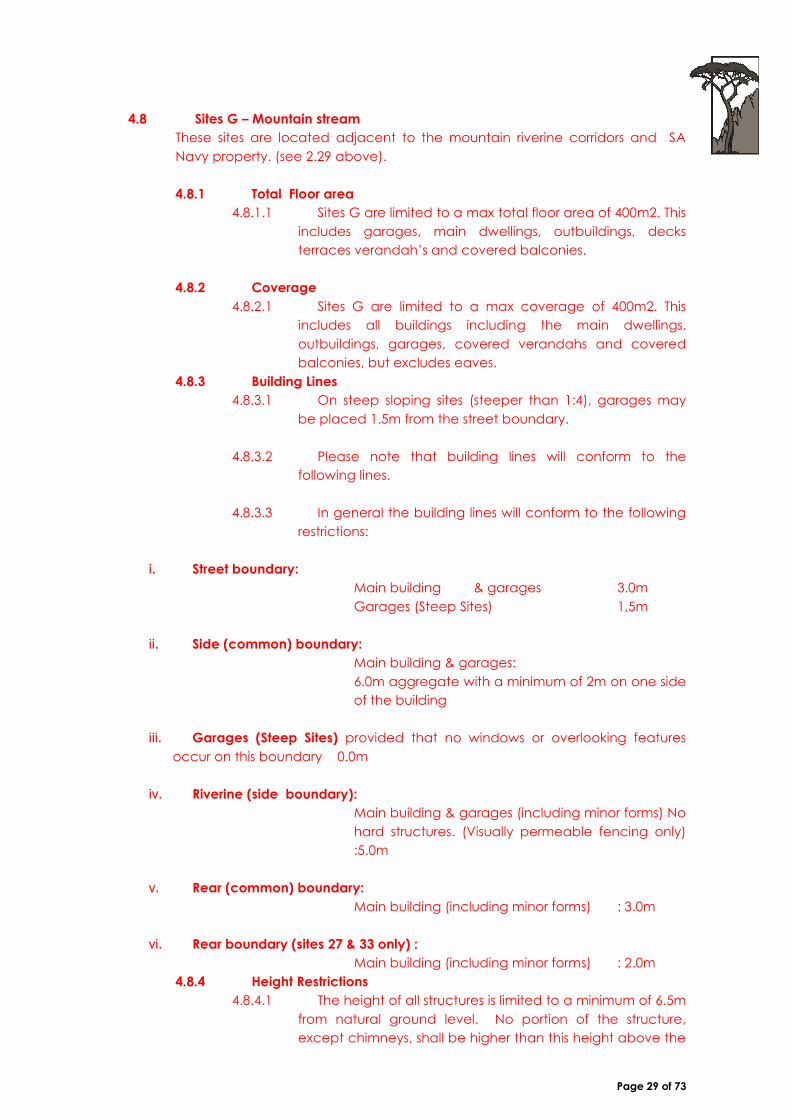
4.8 Sites G – Mountain stream
These sites are located adjacent to the mountain riverine corridors and SA
Navy property. (see 2.29 above).
4.8.1 Total Floor area
4.8.1.1 Sites G are limited to a max total floor area of 400m2. This
includes garages, main dwellings, outbuildings, decks
terraces verandah’s and covered balconies.
4.8.2 Coverage
4.8.2.1 Sites G are limited to a max coverage of 400m2. This
includes all buildings including the main dwellings,
outbuildings, garages, covered verandahs and covered
balconies, but excludes eaves.
4.8.3 Building Lines
4.8.3.1 On steep sloping sites (steeper than 1:4), garages may
be placed 1.5m from the street boundary.
4.8.3.2 Please note that building lines will conform to the
following lines.
4.8.3.3 In general the building lines will conform to the following
restrictions:
i. Street boundary:
Main building & garages 3.0m
Garages (Steep Sites) 1,5m
ii. Side (common) boundary:
Main building & garages:
6.0m aggregate with a minimum of 2m on one side
of the building
iii. Garages (Steep Sites) provided that no windows or overlooking features
occur on this boundary 0.0m
iv. Riverine (side boundary):
Main building & garages (including minor forms) No
hard structures. (Visually permeable fencing only)
:5.0m
v. Rear (common) boundary:
Main building (including minor forms) : 3.0m
vi. Rear boundary (sites 27 & 33 only) :
Main building (including minor forms) : 2.0m
4.8.4 Height Restrictions
4.8.4.1 The height of all structures is limited to a minimum of 6.5m
from natural ground level. No portion of the structure,
except chimneys, shall be higher than this height above the

Page 30 of 73
point of the natural ground level immediately below it.
4.8.5 Parking
4.8.5.1 Provision must be made for minimum of four onsite
parking bays (inclusive of garaging) on each site.
4.8.6 Fencing
4.8.6.1 Visually permeable fencing must be installed on the
riverine side of the property, and Urban edges (South
boundary abutting the Estate security fence SA Navy).
4.8.6.2 A servitude ROW of 1,2m to provide access to service &
patrol the perimeter security fence ( SA Navy) abutting this
fence will registered. The homeowner must erect a safety
fence or similar approved visually permeable barrier to
keep persons 1,2m from the perimeter fence (min Height
1,2m).
4.8.6.3 A landscape zone, 2m wide from the rear of the
property for sites 198, 210 & 217 must be installed by the
homeowner. This is to be densely landscaped with planting
and tall shrubs to screen the sites with “Tarchonanthus
Campharatus” or Camphor Bush a mimimum of 70L plant
each 2m.
4.8.6.4 In addition the Developer intends to install a landscaped
earth berm, behind the sites 210-217, on Navy property
(subject to agreement) to act as an additional screening
element.
4.8.7 Environmental Contract SEMP & OEMP
4.8.7.1 A Site Environmental Management Plan (SEMP) and the
Operational Environmental Management Plan (OEMP) are
required to be approved by the Environmental Site Officer
(ESO), prior to construction activity, including excavation
and / or any site clearing and site establishment.
FOURTH DRAFT AMENDMENT: 2011/02/17 - Insertion of Definition
4.9 Floor Space
i. Floor space in relation to a dwelling house means the area of every floor of
the dwelling as measured from the inner face of the exterior walls or
similar supports of such dwelling. When the dwelling consists of more
than one storey, the total floor space shall be the sum of the floor space
of all the storeys.
ii. For the purpose of measuring maximum floor space, garages, outbuilding
and covered balconies, terraces, patios and verandahs shall be
included.

Page 31 of 73
Note
As the limitation on floor space was intended to limit the “Visual Impact” on the
mountainside. It is therefore proposed that where this visual impact is “hidden” or
“concealed”, that the space that is concealed from view, and complies with the Zoning
schemes more restrictive interpretation of “basement” Clause 60(6) whereby coverage and
setback are unaffected by spaces “wholly below ground” are permitted. As the natural
ground level (NGL) has been documented and this will prohibit manipulation of the NGL to
create additional height and therefore any impact has been effectively controlled by this,
the following “Total Floor Space” description is therefore proposed:
4.9.1 Total Floor Area sites F & G
i. Any spaces that are “Wholly Below” the Natural Ground level (NGL), will not
be deemed to be included. Provided where any areas “wholly below”
the NGL. Should this space project beyond the 400 sqm coverage
footprint the areas must be covered with a min of 750mm of soil & are
planted with landscaping (ref diag X). The finished ground level
abutting these spaces may only be below the ceiling of the space for
access stairs (max width 1,5m), ventilation slots (max width 1,5m), (Diag
Z) vehicle entrances (max width 4,8m) which may not be visible from
any public area (road, riverine area, P.O.S, etc) on the Estate refer
diagram Y).
(a) (b) (c)
Diagram X Total Floor Area Exclusion - Areas must be “Wholly under ground” * (areas
to be under legal footprint (b), or if projecting beyond the legal
footprint must be covered by 750 mm soil & landscaping(a), or must
be concealed from view with earth retaining and be a min of 1m
below the NGL (b).

Page 32 of 73
(c)
(D) (C)
Diagram Y Total Floor Area Exclusion - Areas to be “Wholly underground” *
Access to areas to be concealed from P.O.S. or riverine areas (c), or
concealed from street (d), such as garage entrances (c)
(e) (f)
Diagram Z Total Floor Area Exclusion - Areas to be “Wholly underground” * Vent
/ stair slots max width 1,5m (e) garage opening (f) max width to be
4,8m, and to be concealed from street, public places, (read with
diagram Y).

Page 33 of 73
5. ROOFS
5.1 General
5.1.1 It is encouraged that major plan forms are to be broken up into
individual components and roofed individually.
5.1.2 The roofs can be linked with flat concrete or corrugated roofs; or
other connecting elements. This may be necessary in order to
accommodate level changes.
5.2 Permissible Major Roof Forms:
It is intended to allow a number of different roof forms in order to allow
architectural expression and create variety.
5.2.1 Symmetrical double-pitched roofs with a pitch of 17°-35° and a
maximum span of 7m.
5.2.2 Simple mono-pitches with a minimum pitch of 10°-17°. Roofs to follow
the slope. Please note that in the event of using a mono-pitched roof
adjacent to a street boundary, the vertical face of the wall may not be
higher than 5.5m.
5.2.3 Asymmetrical double pitched roofs i.e. one length shorter than the
other where longer length shall follow the slope of the site (roof pitch
between 17°-35°).
5.2.4 Hipped roofs on rectangular building forms with a pitch of 17°-35°. All
the roof pitches of the various roof forms (major elements) of one house
shall be of the same pitch.
DIAGRAM 4: Permissible Roof Forms
5.3 Minor Roof Forms & Linking Roofs:
5.3.1 Lean-to and verandah
roofs shall have a pitch
between 5° and 25°.
5.3.2 A flat roof (minor
element) needs to be
incorporated on any 0.0m
building line.
5.3.3 No overlooking features
on side boundaries (see
2.17).
Page 34 of 73
5.4 Garage Roofs
5.4.1 Inclusion of garages as part of a major building form is encouraged.
5.4.2 Free standing or semi-detached garages should be roofed with a
flat concrete or corrugated roof concealed by parapet walls.
5.5 Gables & Eaves
5.5.1 Large eaves are generally recommended, in order to shade large
areas of glass. Roofs must extend over walls, with a minimum overhang
of 1000mm. Eaves overhang is 1000m from the finished exterior wall
surface.
5.5.2 No clipped eaves will be allowed.
5.6 Roof Lights and Roof Windows
5.6.1 Roof lights and roof windows are to be set into the plane of the roof.
Max size 780mm x 1400mm.
5.6.2 Dormer windows are not allowed.
5.7 Roof Materials & Colour
5.7.1 Materials for roof finishes must be natural slate, or corrugated iron.
5.7.2 Glazing may be used on verandah roofs, but must be limited to a
portion of the roof set in from the outside edge.
5.7.3 Flat concrete roof elements will be limited to 20% of the total floor
space of the house.
5.7.4 Flat roofed areas are to be finished in natural stonechip, in brown or
grey colours, if not utilized as roof decks. Reflective finishes or aluminum
paint are not allowed.
5.7.5 Colours and specification will be part of the detailed specification
document.
Page 35 of 73
FIRST DRAFT AMENDMENT: 2006/12/05
5.8 Roofs
5.8.1 Flat Roof Controls
(Are considered to be any roofs less than 5 degrees )
Are not limited to concrete roofs only but inclusive of
Chromadeck & Kliplock roofing as well
5.8.2 Roofscapes
A uniform Roof type per home is required.
Only a grouping of the same roof type will be permitted for a home, as
per Diagram 4.
6. WALL CONSTRUCTION AND FINISHES
6.1 Walls may be constructed of clay brickwork. No facebrick shall be
permitted.
6.2 All external masonry walls to be at least 280mm cavity wall construction.
6.3 30% of the surface of the walls of al building form (including garages) may
be of “ship lapped” hardwood boarding.
6.4 20% of the external walls of al building form (including garages) may be
constructed or dressed with natural stone. The stone can be used to create a
plinth (600mm) or to create a feature wall of natural stone.
6.5 Decorative plaster mouldings, quoins or rustication will not be permitted.
6.6 Wall colours shall be selected from the natural colour palette as prescribed
in the specification document.
SECOND DRAFT AMENDMENT: 2008/06/17/06
6.7 Wall Finishes
i. Bagged walls are not permitted as an exterior wall finish.
ii. The exterior wall finish shall be a smooth plaster finish.

Page 36 of 73
7. WINDOW TYPES AND FINISHES
In the design of fenestration it is intended there should be large glass areas where the
walls give way to glazing, to take advantage of the views, whilst other smaller windows
are set within solid wall planes as “punctures/ apertures”.
7.1 Windows may be any type, and have any form and proportion, except for the
following:
i. “Windblock” type window frames
ii. Plastic (PVC) frames
iii. Reflective glass
iv. Cottage pane windows
7.2 Splayed windows will not be permitted
DIAGRAM 5: WINDOW SECTIONS
7.3 Large areas of glass should be shaded by roof overhangs.
7.4 Materials may be natural or painted timber, epoxy coated or anodized aluminum
7.5 Colours: The following information to be part of the specification list.
8. DOOR TYPES AND FINISHES
8.1 All door openings to have rectilinear proportions. No arches will be permitted.
8.2 The following doors will not be permitted:
Ornate and carved doors
Cottage pane frames
8.3 Garage Doors are to be of the horizontal slat type in either timber, aluminum or
steel.
8.4 Materials may be natural or painted timber, epoxy coated or anodized
aluminum.
8.5 Colours: The following information to be part of the specification list.
9. SHUTTERS
9.1 The use of shutters is encouraged. Non-functional shutters will not be permitted.
9.2 The material and finishes to match the windows and doors of the house.

Page 37 of 73
10. BURGLAR BARS
10.1 Designs should be simple, without ornate detail. All designs are subject to
review by the Design Review Committee.
10.2 No external burglar bars will be permitted
10.3 No “Trellidoor” or other metal security doors will be allowed externally.
11. EXTERNAL BUILT ELEMENTS
11.1 Perimeter Fences and Boundary Walls:
11.1.1 Continuous boundary walls or fences on street boundaries shall not be more
than 40% of any street boundary. The placement of building components
should be used to create enclosure and privacy of garden spaces.
Landscaping should further be used to create privacy where required. If
additional fencing is required, this should be set back to b building line, or
beyond this line.
DIAGRAM 6: Boundary Enclosure
11.1.2 Fragmented walls, enclosing gardens and courts to either side of the main
buildings, are encouraged. Low walls (max 1.2m high) should be used to
create external “rooms” associated with and directly linked to buildings to form
courtyards.
11.1.3 Boundary fences on common boundaries are restricted to 1.8m visually
permeable and 1.2m if visually non-permeable. Refer to the Manual for
Boundary wall Design
11.1.4 No “vibracrete” walls will be allowed. The style of the fence shall either match
the architectural style of the building, or match the aesthetic of the Estate,
namely low stone walls or stone columns with steel palisade. All stonework is to
be done by a stonemason approved by the estate/ developer and palisade
type and colour is to match the palisade used elsewhere on the estate. No
artificial rock to be used in lieu of genuine rock.

Page 38 of 73
FIRST DRAFT AMENDMENT: 2006/12/05
11.1.5 Drying Yard Walls (Refer to Item 11.1.2)
.
Walls to laundry / refuse / service yards are fully screened and may be 1,8m in height,
with a limit to the size of the yard (say 30 sqm) so that it is controlled. These may only
occur on one common boundary, and be designed in such a way that no long
expanses of wall remain unfragmented, and have a maximum length of 10m.
11.1.6 Screening/ Privacy Walls (No reference in the Design Manual)
Screening/ Privacy Walls for pool areas must be visually attractive and may be
permitted by the DRC upon application provided that the wall blends with the
landscape, such as a stone clad wall (both sides) max ht 1.8m, with a maximum length
of 8m. The wall must not impact visually within the development, and that any such wall
elements be located on common boundaries, not street so as to ensure the visual
impact on the mountain side is controlled. No walls would be permitted on the scenic
routes, Boyes drive, urban/natural and riverine edges.
A Drying yard and Privacy Wall may not exceed the maximum of 10m per site (privacy
walls max 8m, the balance may be used for Drying yard walls).
Group Sites (StoneVillage & StoneClose ) are exempt from the wall height controls as
SDP’s for both sites were pre-approved by the Local Authority .
11.1.7 Heights:
All heights are to be taken from Natural ground Level - NGL as defined in the manual.
Where there is a significant slope then the top of the wall must either slope to follow the
land or if the wall steps (horizontal top of wall) then the max height of wall above the
NGL will be 2.4m.Should cutting occur to lower the ground level below NGL this then
section 11.2 will apply.
THIRD DRAFT AMENDMENT: 2009/07/30
11.1.8 Boundary Walling / Retaining Combinations.
The DRC proposes that any wall that lies between the boundary and the appropriate
building setback line will be considered a boundary wall.
The height is to be taken from NGL (to a max of 2,4m, due to slope of the ground).
If a wall is on top of a retaining structure then it must comply with Diagram 7 of the
design manual and step 1m each 1,2m of height, see diagram 7b i.e. it must be setback
1m from the edge of the retaining wall.

Page 39 of 73
Any structures not setback at the top of a retaining wall must be visually permeable,
refer to section 5 of the design manual for clarification and see diagrams 7b.
Diagram 7b Diagram 7c
The max height of the “visually permeable” fencing (see Diagram 7c above) will be
1,2m above the filled or step level for street facing boundaries.
The max height of the “visually permeable” fencing (see Diagram 7c above) will be
1,8m for common (side or rear) boundaries.
Where a site slopes the max height of a retaining step is to be 1,2m, unless at the
discretion of the DRC ( and neighbours consent is obtained ) it may rise to not more
than 1.6m max above the NGL.
Allowance must be made for the thickness for the stone-cladding to be within the
property boundary.
.
Visually permeable fencing shall be used at the defined residential areas as described
below:
Sites B: on the natural / urban edge side of the portion
Sites C: on the side of the portion that face onto a scenic route
Sites E: on the edge facing Boyes Drive
11.1.9 The use of climbing plants on walls, buildings, trellises and fences and
indigenous shrub screens or informal hedges I to be encouraged.
11.1.10 All fences, screens or walls shall be submitted for the approval of the Design
Review Committee.

Page 40 of 73
FIRST DRAFT AMENDMENT: 2006/12/05
11.2 Visually Permeable Fencing
. .
11.2.1 Boundary Walls & Perimeter Fences (Refer to Item 11.1.3)
All properties are restricted to the 1.2m wall height (solid) or the 1.8m fence
height (visually permeable).
Visually permeable fencing should be a minimum of 50% open, when viewed
from outside. The solid substructure for Planted structures must not exceed 50%
solid, but the planting may become 100%, and hedges are permitted.
The following would be accepted, provided they have a minimum open area
of 50%:
T.E.S.A Serengeti Pallisading Steeldale: Victorian Pale Fencing (square top
only)
Bekaert Beta Bastion Medium panel system
Bekaert Polyester Coated 50mm by 50mm by 25mm weld mesh fencing
(black) with fencing stanchions
Propergate: Custom Pallisading (without spear top)
The above to be in charcoal or matt black. These may be used in
combinations of Brick, stone clad and plastered piers also.Solid piers should be
designed to suit the module of the system chosen but not be less than 3m
apart. The use of all other systems are subject to approval.
As recommended by the estate’s landscape architects,(CNdeV) – palisade
fencing is to match the estate’s perimeter fencing specification ; “Graphite”,
from the Plascon Expressions range (Code E – 29 -7)
SECOND DRAFT AMENDMENT: 2008/06/17
11.3 Palisade Fencing:
The following fencing has been added to the approved list.
Clear Vu 2 per Cochrane Security (021)7831214 (visually permeable fencing) to
the design specs.
This may be used without spike topping , provided it is Black, colour ref RAL
9005 only.
BETAfence Nyloflor Medium, in a charcoal/ antrachit colour is approved. This is
a 4,4mm wire with a 100 x 50mm spacing Panel sizes are available in 2500mm
widths at 3 height options 1539,1730 and 2030.
Page 41 of 73
THIRD DRAFT AMENDMENT: 2009/07/30
11.4 Visually Permeable Fencing:
The design manual specifies that certain fencing must remain visually
permeable. In addition to item 1 of the 1st Draft amendments, the following is
applicable.
11.4.1 Horizontal slat fencing- the spacing between the slats must be equal
to the timber size (structure may be generally ignored if at reasonable
centres, min 1m).
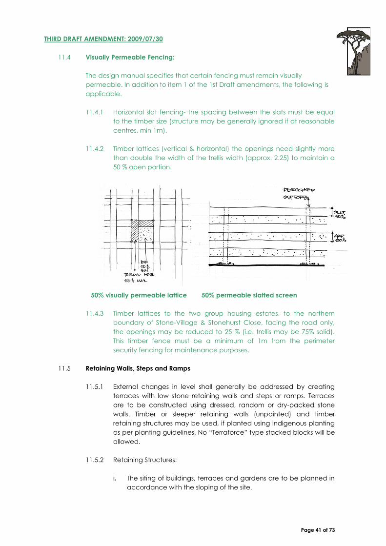
11.4.2 Timber lattices (vertical & horizontal) the openings need slightly more
than double the width of the trellis width (approx. 2.25) to maintain a
50 % open portion.
50% visually permeable lattice 50% permeable slatted screen
11.4.3 Timber lattices to the two group housing estates, to the northern
boundary of Stone-Village & Stonehurst Close, facing the road only,
the openings may be reduced to 25 % (i.e. trellis may be 75% solid).
This timber fence must be a minimum of 1m from the perimeter
security fencing for maintenance purposes.
11.5 Retaining Walls, Steps and Ramps
11.5.1 External changes in level shall generally be addressed by creating
terraces with low stone retaining walls and steps or ramps. Terraces
are to be constructed using dressed, random or dry-packed stone
walls. Timber or sleeper retaining walls (unpainted) and timber
retaining structures may be used, if planted using indigenous planting
as per planting guidelines. No “Terraforce” type stacked blocks will be
allowed.
11.5.2 Retaining Structures:
i. The siting of buildings, terraces and gardens are to be planned in
accordance with the sloping of the site.

Page 42 of 73
ii. No single retaining wall shall exceed 1.2m height. Retaining wall
which exceed this height shall be terraced and stepped back by
at least 1m (see diagram – NOTE: 1.5m indicated on drawing is
incorrect).
DIAGRAM 7: RETAINING WALLS
11.5.3 Materials of retaining walls are to be natural stone. The walls may be
built of stone or with stone facings to masonry backup wall. The stone
may be laid in random rubble or coursed rubble pattern with recessed
cement mortar.
11.5.4 Unpainted Tanalith treated pole retaining structures up to 1.0m may
be used if planted with indigenous plants as per planting guidelines
11.5.5 Finishes permitted on walkways and terraces are:
i. Granite or concrete cobble stones, clay brick pavers in approved
colors, natural sandstone, slate gravel, laterite and timber.
11.5.6 All retaining structures of any nature shall be submitted to the Design
Review Committee (DRC) for approval.
FIRST DRAFT AMENDMENT: 2006/12/05
11.6 Building Platforms
The max cut is 1.2m provided it steps 1m it may be higher, only if stepped. This
may not be exceeded (both in terms of the conditions of approval and design
manual text) -
The 1.2m stepped retainer walls provided it steps as per Diagram 7 of the
Manual, except that the height of each step should read 1.2 (Not 1.5m)
applies to all sites.
Where the DRC is comfortable with the proposal it will only consider cuts that
exceed this with the proviso for steep sites ( greater than 1:4 slope), and that
special application need to be made to the Director planning and
environment, and the applicant should obtain adjoining and abutting
neighbour’s consent, and approval from the Home Owners Association (HOA).

Page 43 of 73
To avoid this some applicants may then wish to fill and create earthed embankments
(without limit), which would be more visible and unsightly, refer Diagram B below. However,
this will be difficult to landscape effectively and maintain and most probably result in
erosion.
We would prefer to have the cut behind the homes between the home and the mountain,
using the stepping guideline of 1,2m (diagram 7). This will have a lesser impact on the estate
and obviously need to be controlled. We therefore propose the following:
Where there is filling the embankment may not exceed 1:3 slope which should resist erosion
if properly landscaped, and to a max height of 3m, measured from the NGL. The
embankment must be well landscaped and shaped to give it a natural appearance, and
must be softened with planting.
We also wish to include gabions (filled with local stones) as a means to construct retaining
walls within the same guidelines, in addition to stone faced walls and tanalith poles. All these
must comply with Diagram A.
THIRD DRAFT AMENDMENT: 2009/07/30
11.7 Retaining Walling
Retaining wall “concealed” by house
Retaining walls behind houses i.e. between a house and a retaining
wall enclosed by the house or a yard, or courtyard, that is not visible
from any surrounding properties, may at the discretion of the DRC
have the stone work omitted. These walls should be a dark colour,
and / or softened and screened with planting ( from below / above).

Page 44 of 73
“Baby Elephant” and “Maison Blanche” are considered to be Dark colours.
All applications must be submitted and approved indicating the stone cladding, but the
Estate may allow this finish to be omitted only upon final inspection (as it is difficult to
establish the amount of screening from plans submitted, or to assess the positions from which
the wall may be viewed from).
Furthermore these concealed walls may exceed the limit of 1.2m height but not more than
2.1m in height (total face of the wall). Engineer’s certification and drawings will be required,
prior to approval.
11.8 Verandahs & Pergolas
11.8.1 Verandah and pergola posts may be masonry, timber or steel, or a
combination of these. These minor forms are to be simple in form and
without imitation of Period Architectural styles.
11.8.2 Colours and materials are to match the windows and doors of the house.
11.8.3 No Victorian cast iron “Broekie Lace” detail will be allowed. Louvred
pergolas shall be permitted (colours need to match doors and window
specification).
11.9 Timber Decks
11.9.1 The maximum height of deck supports shall be 1.2m.
11.9.2 Supports may be of the following types:
i. Double or single timber posts
ii. Steel posts (colour charcoal grey/ black)
iii. Natural stone piers
11.10 Balconies
11.10.1 No balconies will be permitted on common boundaries. Balconies can
only be placed on street boundaries and facing boundaries, which faces
onto an open space.
11.10.2 Floors of balconies are to be finished in materials of neutral shades. They
can be ochre tinted screed, natural stone, slate or natural timber.

Page 45 of 73
FIRST DRAFT AMENDMENT: 2006/12/05/12
Balconies facing only the “Back Boundary” (opposite street) where the property lies below
the street from which access is taken. Should a corner property wish to construct a balcony
the Higher or Mountain facing boundary, will be taken as the front for the purposes of this
interpretation only.
The balcony must be setback from the “back Boundary” according to the Overlooking
regulation. Ref. to section 54 of the Cape town Zoning scheme (Gov Gazette 4649).
The balcony must be screened from the common or side balconies by the building or
flanking walls or screens a minimum of 1.7m high. These screens must comply with the
Overlooking regulation.
All such balconies are still subject to the approval by the Stonehurst DRC and will not
necessarily be approved if they are deemed to infringe on another abutting properties
privacy more than the building may.
FOURTH DRAFT AMENDMENT: 2011/02/17
11.10.3 Common Boundary setback for Balconies: If a balcony is considerably
setback so as to not create privacy the following method to calculate
this is shown as a Balcony Privacy Setback
11.10.4 Balcony privacy setback = OF (Overlooking Feature) distance x 2 + Ht
difference from Finished Floor Level (FFL) of balcony to Natural Ground
Level (NGL) on the boundary opposite the proposed balcony). Ref
Diagram
11.10.5 Overlooking Feature as determined in Section 54 (2) of the CT Zoning
scheme. This is intended to be conservative in controlling privacy, and
takes into account the land fall or rise into account.
11.11 Balustrading
11.11.1 Balustrades may be
constructed from timber or
steel or a combination.
11.11.2 The designs are to be simple,
without ornate detail.
DIAGRAM 8: BALUSTRADING
11.11.3 Individual designs are subject
to approval of the Design
Review Committee

Page 46 of 73
12. EXTERNAL WORKS
12.1 Waste Pipes
12.1.1 All drainage pipes except for low level stub stacks are to be
concealed within walls, unless located within enclosed courtyards.
12.1.2 Rainwater Goods
12.1.3 Rainwater goods to be aluminum or pre-coated galvanized mild steel.
Colours are to blend with the background surfaces.
12.2 Storm Water/ Drainage
12.2.1 Stormwater run-off is to be controlled in order to avoid soil erosion. All
details of stormwater disposal including paving and landscaping are
to be clearly stated in the building plans.
12.2.2 Pre-cast concrete channels will not be allowed. Where channels are
required they shall be constructed in stone, brick or cobble.
12.2.3 Stormwater shall be dispersed in reeded channels/ swales or be
allowed to penetrate within detention areas/ reed-beds before
entering dams in lieu of being piped underground.
THIRD DRAFT AMENDMENT: 2009/07/30
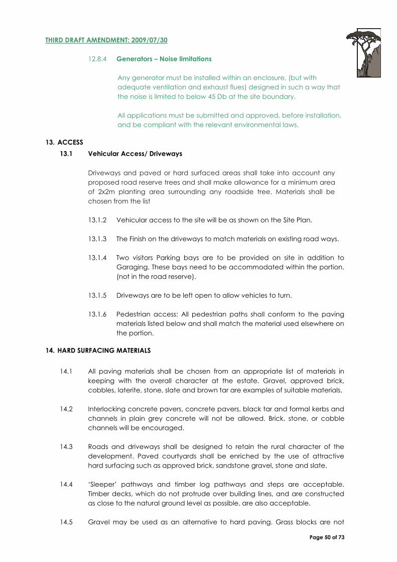
12.2.4 Storm Water Channels
Where it is necessary to install storm
water channels the following options
may be used.
Vee channel formed with Pavers
U channel formed with cobbles.
Combinations of Cobbles
and “Pavatile” transition edges
Storm-water channel options
12.3 External/ Outdoor Lighting
12.3.1 External lighting shall be kept to a minimum. Where required, lights
shall be fixed to walls or columns or should be restricted to garden up-
lighters. Garden uplighters shall be black. External lighting must be low
level (no higher than 1m) and to provide downwardly directed light.
Page 47 of 73
12.3.2 Generally, roads shall not be lit and courtyards and parking areas shall
be minimally lit and restricted to entrance areas, where possible.
Lighting is to be provided by the owner at the vehicle entrance to
property.
12.3.3 No illuminated signage shall be allowed.
12.3.4 All lighting shall be to the approval of the Design Review Committee
THIRD DRAFT AMENDMENT: 2009/07/30
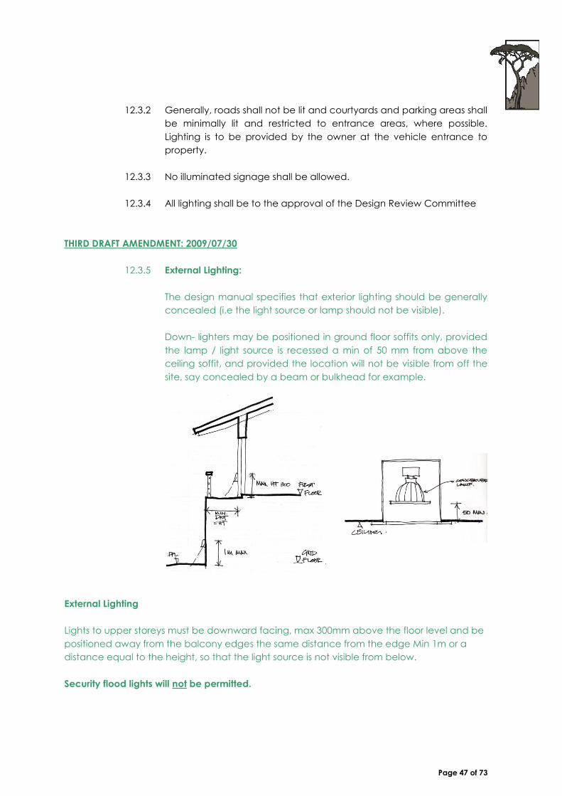
12.3.5 External Lighting:
The design manual specifies that exterior lighting should be generally
concealed (i.e the light source or lamp should not be visible).
Down- lighters may be positioned in ground floor soffits only, provided
the lamp / light source is recessed a min of 50 mm from above the
ceiling soffit, and provided the location will not be visible from off the
site, say concealed by a beam or bulkhead for example.
External Lighting
Lights to upper storeys must be downward facing, max 300mm above the floor level and be
positioned away from the balcony edges the same distance from the edge Min 1m or a
distance equal to the height, so that the light source is not visible from below.
Security flood lights will not be permitted.

Page 48 of 73
12.4 Signage, Lettering And Numbering
12.4.1 No illuminated signage will be permitted
12.4.2 Lettering or numbers are to be a maximum of 150mm in height. See
design manual for signage specification.
12.4.3 Signage and house numbering shall conform to the guidelines and
shall be indicated on building plans. All such numbering and signage
shall be attached to the building or onto walls where possible and
must be shown on building elevations.
12.5 Swimming Pools and Water Features
Water features and swimming pools are to be designed in the style and
character of the estate. ‘Rock’ or ‘beach’ pools and artificial rock are
inappropriate. Water features, fountains and pools should be used to link the
internal with the external and cool external spaces such as courtyards and
verandahs.
12.5.1 All pools and water features shall form part of the approval process by
the DRC.
12.5.2 Pool fences shall conform to National building regulations, but should
be constructed from palisade to match other fencing within the
development/ portion. Off-the-shelf pool fencing shall not be allowed,
unless approved by the DRC and only in an acceptable colour.
(charcoal grey, black).
12.5.3 Backwash from the filter is to be dealt with in accordance with Local
Authority regulations. Swimming pool pumps must be screened from
view. The position of the pump is subject to approval by the Design
Review Committee.
THIRD DRAFT AMENDMENT: 2009/07/30
12.5.4 Pool safety- Water features ponds fountains, etc .
Any pool or Water feature, pond or fountain (deeper than 300mm),
must be protected in terms of SABS 0400 DD4.
12.6 Outbuildings, Carports and other Secondary Elements
12.6.1 ‘Wendy houses’ and sheds shall not be permitted. Single or double
carports
12.6.2
12.6.3 to match the roof of the garage or main house. The supporting posts
and roof of the carport will follow the same specifications as for

Page 49 of 73
verandahs/ pergolas.
12.6.4 Guest cottages/ granny flats will be considered.
FIRST DRAFT AMENDMENT: 2006/12/05
12.6.5 Second Dwellings
The Zoning Approval for the Stonehurst Mountain Estate is for Single
Dwelling Residential and for Group Dwelling Houses (i.e. one unit per
Erf)
Granny flats, will be considered, provided due process is followed, i.e.
a departure application is made, neighbours consents are obtained,
and the HOA consents.
Granny Flats will be subject to the following constraints: these shall be
no larger than 120 sqm, are to be adjoined to the Main house using
an inter-leading door. An extra parking bay must be provided.
12.7 Laundry and Refuse Areas
12.7.1 Laundry and refuse storage should remain fully concealed within
courtyards. See Perimeter fences and boundary walls for restrictions
regarding courtyards.
12.8 Other Services
12.8.1 Television aerials and satellite dishes are to be positioned as discretely
as possible and subject to the approval of the DRC.
12.8.2 No solar panels will be allowed.
SECOND DRAFT AMENDMENT: 2008/06/17
12.8.3 Solar Heating (to be read in conjunction with Addendum 1)
The following guidelines should be followed should an owner wish to
install Solar water heating, in compliance with COCT regulations
Solar panels to be hidden from view
Integrated with the design where possible
Positioned flush on flat roofs or between roofs at the same
pitch as the adjacent roof.
Must not create reflective visible surfaces.
Colour to be matt black, charcoal.
Only to comply with by-law regulations. On application from DRC
Page 50 of 73
THIRD DRAFT AMENDMENT: 2009/07/30
12.8.4 Generators – Noise limitations
Any generator must be installed within an enclosure, (but with
adequate ventilation and exhaust flues) designed in such a way that
the noise is limited to below 45 Db at the site boundary.
All applications must be submitted and approved, before installation,
and be compliant with the relevant environmental laws.
13. ACCESS
13.1 Vehicular Access/ Driveways
Driveways and paved or hard surfaced areas shall take into account any
proposed road reserve trees and shall make allowance for a minimum area
of 2x2m planting area surrounding any roadside tree. Materials shall be
chosen from the list
13.1.2 Vehicular access to the site will be as shown on the Site Plan.
13.1.3 The Finish on the driveways to match materials on existing road ways.
13.1.4 Two visitors Parking bays are to be provided on site in addition to
Garaging. These bays need to be accommodated within the portion.
(not in the road reserve).
13.1.5 Driveways are to be left open to allow vehicles to turn.
13.1.6 Pedestrian access: All pedestrian paths shall conform to the paving
materials listed below and shall match the material used elsewhere on
the portion.
14. HARD SURFACING MATERIALS
14.1 All paving materials shall be chosen from an appropriate list of materials in
keeping with the overall character at the estate. Gravel, approved brick,
cobbles, laterite, stone, slate and brown tar are examples of suitable materials.
14.2 Interlocking concrete pavers, concrete pavers, black tar and formal kerbs and
channels in plain grey concrete will not be allowed. Brick, stone, or cobble
channels will be encouraged.
14.3 Roads and driveways shall be designed to retain the rural character of the
development. Paved courtyards shall be enriched by the use of attractive
hard surfacing such as approved brick, sandstone gravel, stone and slate.
14.4 ‘Sleeper’ pathways and timber log pathways and steps are acceptable.
Timber decks, which do not protrude over building lines, and are constructed
as close to the natural ground level as possible, are also acceptable.
14.5 Gravel may be used as an alternative to hard paving. Grass blocks are not

Page 51 of 73
recommended.
14.6 All paving materials and paving plans are to be approved by the Design
Review Committee/ estate developer or HOA.
14.7 The following brick colours will be acceptable:
i. Corobrik:
Bronze Paver
Wheatstone Paver
Autumn Paver
ii. Crammix:
Saharah Sand Paver
14.8 The following concrete products will be acceptable:
iii. Smartstone
Cobbles and pavers in sandstone colour
iv. Pavatile
Cobbles and pavers in sandstone colour / colour 157
v. Revelstone
Cobbles and pavers in sandstone colour
vi. Okavongo Paving
Okavango plaza 80mm exposed aggregate paver in sandstone
colour
14.9 The following exposed aggregate in-situ paving will be acceptable: Exposed
aggregate concrete, using 6-13mm Prima sandstone from Prima Quarries or
similar approved source.
14.10 The Following natural stone will be acceptable:
i. Sandstone Sandstone tiles or rocks set in natural ground or concrete,
(‘stone pitching’). Cement joints should be kept to approximately 5cm
maximum width on average and should be laid by an approved
stonemason.
ii. Slate ‘Desert Sand’ or ‘Rich Autumn’ available from Strata or Mazista.
iii. Gravel
The following gravel will be acceptable: 6-13mm size Prima sandstone in a 20
to 50mm layer. All gravel is to be laid on a compacted sub-base.
15. ENVIRONMENTAL/ SOFT LANDSCAPING CONTROLS
15.1 Site Clearing
15.1.1 No trees or vegetation outside the building area of each site may be
removed without approval of the Design Review Committee.
15.1.2 Damage to trees and vegetation on any land unit will be subject to

Page 52 of 73
penalties in accordance with the Environmental Management Plan.
15.1.3 Damage to trees and vegetation on Common Property will be subject
to penalties in accordance with the Environmental Management
Plan.
15.2 Planting Character
15.2.1 With the exception of fully enclosed courtyards, all trees and shrubs
shall be indigenous to the Western Cape. A list of proposed plants
follows as a guide. No invasive alien or invasive exotic plants will be
allowed anywhere on the estate. Shrubs and groundcovers shall be
chosen in keeping with the style and character of the estate. The style
may be loosely defined as indigenous and rustic.
15.2.2 Climbing plants and creepers shall be encouraged to cover walls,
create shade under pergolas and climb buildings to soften hard
edges and surfaces.
15.2.3 The use of informal hedges is encouraged.
15.2.4 Non-invasive lawn species should be used. Buffalo lawn is proposed.
15.2.5 The use of ‘tropical’ plants such as palms, banana trees, Scheffleras,
Phormiums, yuccas and/ or Strelitzia is seen to be inappropriate. The
use of ‘Mediterranean’ plans such as cypresses, lavender and
Bougainvillea is also discouraged.
15.2.6 The use of plants indigenous specifically to the site is proposed.
15.2.7 Generally, the style should be relatively informal.
THIRD DRAFT AMENDMENT: 2009/07/30
15.2.8 Landscaping requirements - Trees
The design manual specifies that landscaping has certain plant types
but is not prescriptive, as to the combination of these.
Trees are to be planted at a minimum of 1 tree (minimum 20 litre) per
250sqm of erf size.
Site 0 - 250 sqm 1 tree min
Site 250 - 500 sqm 2 trees min
Site 500 - 750 sqm 3 trees min
Site 750 - 1000 sqm 4 trees min
Site 1000 > sqm 5 trees min

Page 53 of 73
15.3 Sidewalk/ Roadside Planting
15.3.1 Planting on roadsides or on sidewalks or embankments must be
planted using shrubs and groundcovers chosen from the proposed list
and must be planted to blend in with indigenous and adjacent areas.
LANDSCAPING AMENDMENT
15.3.2 Environmental / Soft Landscaping Controls
Sidewalk / Roadside Planting
As per clause 9.4 of the Stonehurst Owners Constitution, which states
that “Members shall be responsible to landscape and maintain, at
their own cost, the road verge/s separating their erf from the road/s”.
i. Verges / sidewalks are to be fully landscaped and irrigated to
form part of the adjacent garden as well as to tie in with any
existing verge landscaping.
ii. A fully landscaped verge is preferred, although residents are
permitted to allocate a portion of their verges for off-road
parking.
The following specifications will apply:
Paved / gravelled verge area (including the driveway) is permitted to be the lesser of
either 50% of the verge length or a maximum of 18meters in length.
The paved / gravelled verge area must not be continuous. These hard areas must be
interspersed with areas of landscaping to create a fragmented effect.
The parking bay width may not exceed 2.5 meters in width and must be parallel to the
road.
The landscaped area must be planted with a minimum of three (3) different plant
species. No mono-cultures of planting will be permitted. (See figure 1). No grassed
verges will be permitted
Figure 1: Schematic diagram of example off-road parking and verge landscaping

Page 54 of 73
The following materials may be used:
200mm x 200mm approved sandstone aggregate paving blocks or
Approved cobbles, both to match those on the adjoining roadside.
Crushed Malmesbury 19mm stone chips.
The verge landscaping is to be submitted to the DRC along with a full landscape plan for
approval.
15.3.3 Planting Character
The design manual requires that only buffalo lawn (Stenotaphrum
secundatum) is permitted. Several requests from the homeowners for
an alternative species of lawn have resulted in the design review
committee recommending the following alternatives:
Cynodon dactylon (Kweek)
Paspalum vaginatum (Country Club)
15.4 Plant List
15.4.1 Shrubs
15.4.1.1 Agathosma ciliaris
15.4.1.2 Crassula coccinea (mountain slopes)
15.4.1.3 Chondropetalum sp.
15.4.1.4 Chrysanthemoides monilifera
15.4.1.5 Coleonema album
15.4.1.6 Colpoon compressum (Cape sumach)
15.4.1.7 Erica baccans
15.4.1.8 Erica capensis
15.4.1.9 Erica laeta
15.4.1.10 Erica mammosa
15.4.1.11 Eriocephalis africanus
15.4.1.12 Halleria lucida
15.4.1.13 Indigofera filifolia
15.4.1.14 Lampranthus falciformis
15.4.1.15 Leucadendron salignum
15.4.1.16 Leucospermum cordifolium
15.4.1.17 Lobostemon argenteus/ Lobostemon glaucophyllus
15.4.1.18 Maytenus heterophlla
15.4.1.19 Metalasia muricata
15.4.1.20 Mimetes cucullatus
15.4.1.21 Muraltia heisteria
15.4.1.22 Pelargonium cucculatum
15.4.1.23 Podalyria calyptrate
15.4.1.24 Podalyria seicea

Page 55 of 73
15.4.1.25 Polygala myrtifolia
15.4.1.26 Protea nitda
15.4.1.27 Protea repens
15.4.1.28 Pterocelastrus tricuspidatus (candle wood)
15.4.1.29 Salvia africana
15.4.1.30 Salvia chamelaeagnea
15.4.2 Groundcovers
15.4.2.1 Agapanthus africanus
15.4.2.2 Crassula capensis
15.4.2.3 Crassula cocinea
15.4.2.4 Crassula flava
15.4.2.5 Diosma oppositifolia (wild buchu)
15.4.2.6 Erica cerinthoides
15.4.2.7 Erica hirtiflora (mountain slopes and marshes)
15.4.2.8 Erica obliqua
15.4.2.9 Erica pulchella
15.4.2.10 Erica viscaria var. decora
15.4.2.11 Lampranthus falciformis (mountains and mountain slopes)
15.4.2.12 Pelargonium betulinum
15.4.2.13 Pelargonium capitatum
15.4.2.14 Pelargonium peltatum
15.4.2.15 Pelargonium pinnatum
15.4.2.16 Tritoniopsis Triticea – (dry stony ground upper mountain
slopes and plateaux)
15.4.2.17 Sutera hispida (hill slopes)
15.4.3 Bulbs
15.4.3.1 Amaryllis belladonna
15.4.3.2 Cyrtanthus ventricosus
15.4.3.3 Watsonia barbonica
15.4.3.4 Watsonia marginata
15.4.3.5 Watsonia tabularis
15.4.4 Wetland/ water plants
15.4.4.1 Aponogeton distachyos
15.4.4.2 Aristea major
15.4.4.3 Chondropetalum tectorum
15.4.4.4 Elegia capensis
15.4.4.5 Psoralea aphylla
15.4.4.6 Psoralea pinnata
15.4.4.7 Spiloxene alba
15.4.4.8 Spiloxene aquatica
15.4.4.9 Wachendorfia paniculata
15.4.4.10 Wahlenbergia procumbens
15.4.4.11 Zantedeschia aethiopica

Page 56 of 73
15.4.5 Tree Species
15.4.5.1 Brabejum stellatifolium (wild almond)
15.4.5.2 Cassine peragua (cape saffron)
15.4.5.3 Cunonla capensus (Butterspoon tree)
15.4.5.4 Curtisia dentata
15.4.5.5 Ilrx mitis
15.4.5.6 Kiggelaria africana (wild peach)
15.4.5.7 Maytenus oleoides
15.4.5.8 Olea capensis (ironwood)
15.4.5.9 Olea europaea subsp. Africana (wild olive)
15.4.5.10 Podocarpus latifolius (real yellowwood)
15.4.5.11 Rapanea melanophloeos (cape beech)
15.4.5.12 Rhus angustifolia
15.4.5.13 Rhus glauca
15.4.5.14 Rhus mucronata/ laevigata
15.4.5.15 Virgilia oroboides
15.4.5.16 Widdringtonia nodiflora
15.4.6 Climbing plants
15.4.6.1 Clematis brachiata
15.4.6.2 Jasminum multipartitum (starry jasmine, indigenous to
eastern cape)
15.4.6.3 Podranea ricasoliana (port st johns creeper, eastern cape)
15.4.6.4 Rhoicissus tomentosa (wild grape)
15.4.6.5 Senecio macroglossus (flowering ivy, eastern cape)
15.4.7 Hedge species
15.4.7.1 Chrysanthemoides monilifera (bietou, low hedge)
15.4.7.2 Dodonaea angustifolia
15.4.7.3 Dovyalis caffra
15.4.7.4 Plumbago auriculata (cape leadwort, low, informal hedge)
15.4.7.5 Rhus crenata
15.4.7.6 Rhus laevigata/ mucronata
15.4.7.7 Tarchonanthus camphorates

Page 57 of 73
16. FIRE PRECAUTIONS
16.1 Due to the forest vegetation on the site there is a higher than normal fire risk. Each
owner should familiarize themselves with the position of hydrants and hose-reels on
the site and with any rules and procedures lay down by the SHOA.
16.2 The water supply to each portion shall be a 40mm connection.
16.3 A fire hose-reel is to be mounted in a position convenient to and visible from the
road, on each portion.
16.4 All owners are encouraged to install sprinkler irrigation systems on the area
surrounding the house and possible on the roof. Any PVC pipe work for these systems
should be buried a minimum of 400mm deep.
16.5 The flues of Fireplaces are to be fitted with brass mesh to prevent sparks escaping.
Braai places shall be built with flues.
16.6 It is recommended that gutters be not installed as the leaf matter that can collect is
a fire hazard. Where gutters are not used, storm water runoff must be dealt with in an
alternative manner. Gutters should be fitted with mesh guards to prevent leaf matter
collecting.
16.7 It is recommended that the design be modified where possible by incorporating fire
prevention measures such as those obtained from “The Complete Australian Bushfire
Book”.
SECOND DRAFT AMENDMENT: 2008/06/17
16.8 Fire Safety- Spark Control
The design manual requested a brass mesh to
chimneys. Following discussions with fireplace
manufacturers the following specification has been
adopted as a minimum requirement of 10mm x
10mm.
Framed expanded metal mesh to be fitted inside the chimney flue brickwork (at its top).
Mentis Flatex Mesh Code 352/VEM 6318 F (see attached). The mesh can be welded onto a
5mm flat steel frame and dropped onto 4 screws/nails inside the chimney opening.

Page 58 of 73
17. ARCHITECTURAL & LANDSCAPE REVIEW AND PLAN SUBMISSION PROCESS
17.6 Submission to Design Review Committee
17.6.1 Building plans may only be submitted to local authority, once it has
been approved by the Stonehurst Home Owners Association.
17.6.2 To facilitate the approval process by the SHOA, sketch plans should
be submitted for approval, prior to the preparation of the final
submission drawings.
17.6.3 Plans submitted to the Stonehurst Homeowners Association for
approval shall include the following information:
i. 1:200 Site plan showing roof plan Building Lines, contours, existing
trees as marked on site indicating those to be removed and
retained, hard and soft landscaping, driveways and
carriageway crossings.
ii. 1:100 Floor plans showing: retaining walls, pergolas, terraces,
Floor space measured in accordance with the definition per
floor. All Elevations 1:100 showing levels, heights, materials and
finishes.
iii. Longitude section taken through slope of site and showing site
boundaries, natural ground line, finished ground line and
heights. Levels to be related to actual levels taken from Land
Surveyors survey drawings.
iv. Completion of checklist as supplied by SHOA
v. 1:100 or 1:200 Landscape Plan showing contours, existing and
new trees, trees to be removed, if any building outline, all
external structures e.g. decks, pools and water features,
pergolas and gazebos, paved areas, paths, terraces and
retaining structures, irrigation sleeves. The Landscape plan must
also include a list of plants for the proposed landscape, these
plants shall be selected form the list of plants included in this
guideline document.
vi. 1:100 or 1:200 Irrigation plan showing position of control points,
connections to mains.
17.6.4 Two sets of drawings pertaining to the buildings are to be submitted to
the SHOA.
17.6.5 A SHOA submission and scrutiny fee for reviewing, altering and
approving plans shall be required.

Page 59 of 73
THIRD DRAFT AMENDMENT: 2009/07/30
17.6.6 Information required on all plans.
In order to facilitate the reviewing of plans correctly the following
information is required.
i. Rider plans to be coloured in to clearly indicate changes.
Changes not coloured will not be deemed to have been
previously approved.
ii. Heights of floor levels MSL
iii. Ridge apex heights MSL.
iv. Contours (MSL) on each plan level including roof plan.
v. Boundary walls to be drawn on elevation/ with top of wall levels
(MSL) and NGL at the base of the wall must clearly annotated.
Wall Heights
LANDSCAPING AMENDMENT
17.6.7 REQUIREMENTS FOR A LANDSCAPE PLAN SUBMISSION:
PLAN SUBMISSION MUST INCLUDE:
i. At least 2 copies of landscape plans at a scale of 1: 100 or 1:
50.
ii. The ground floor plan of any buildings must be indicated, on
an overall site plan.
iii. The plan (shape, size) and specification (type, colour, size,
height) of any hard landscape materials such as steps, shade
structures, pergolas, braais, paving, decking, gravel, stepping
stones, swimming pools, retaining walls etc.
iv. The plan must indicate the position of lawn areas, shrub areas
and trees.

Page 60 of 73
v. The plan must specify what type of plants, lawn and trees will
be used, including those for the road verge.
vi. Plan must specify that all verge areas will be irrigated. Owners
are also encouraged to install irrigation on their properties.
vii. Plant densities must be indicated (i.e. how many plants per
m2).
viii. Trees and shrub sizes must also be specified.
ix. In addition, the drawing will need to include:
Screening plants, i.e., trees and shrubs along the
boundaries.
A Legend or Key should be used indicating Sizes, (Kg /
Litres), and Quantities per square meter and plant species.
Sections and detailing through all retaining structures. These
may need to be verified by an engineer on the
recommendation of the Design Review Committee.
Stormwater Management Plan to indicate the surface and
underground management of stormwater dispersal and
how this integrates into the overall stormwater dispersal of
the surrounding properties, common land and roads.
17.7 Submission of Council Drawings to SHOA
These should include:
17.7.1 The set of council submission drawings to be submitted to the SHOA,
prior to submission to the South Peninsula Municipality. These drawings
may only be submitted, after the final sketch plan approval by DRC.
The drawings need to comply with requirements of local authority, but
should include the following:
17.7.1.1 A 1:200 computer generated, or physical model of the site,
and the design proposal with a detailed description of the
finishes, and the hard and soft landscaping proposed.
17.7.1.2 Six sets of drawings need to be submitted to the SHOA. One
set will be retained by the SHOA for their records. The
approved plans will be returned for submission to the local
authority.
Page 61 of 73
17.8 Local Authority Plan Approval
17.8.1 On approval of the sketch plans by SHOA, drawings can be prepared
for submission to the South Peninsula Municipality – in terms of the
National Building Regulations and the Local Authority Requirements.
17.8.2 All submissions are to be the responsibility of the owner/ Architect.
DISCLAIMERS
17.9 This document is considered supplementary to the National Building
Regulations (NBR) and cannot take precedence. Should any provisions of this
document be regarded as contrary to the NBR, then the NBR shall prevail.
17.10 This document is considered supplementary to the Local Authority
requirements and the conditions contained in the land use approvals (dated
14 February 2005) and cannot take precedence. Should any provisions of this
document be regarded as contrary to the Local Authority requirements or the
conditions contained in the land use approvals (dated 14 February 2005), then
the Local Authority requirements and the conditions contained in the land use
approvals (dated 14 February 2005) shall prevail, except for the aesthetic or
architectural approval, which remains at the discretion of the Design Review
Committee.
17.11 This document is to be considered supplementary to the Home Owners’
Constitution and cannot take precedence. Should any provisions to this
document be regarded as contrary to the Homeowners’ Constitution, then the
Home Owners’ Constitution shall prevail.
17.12 This document is to be considered supplementary to the National Building
Regulations (NBR) and cannot take precedence. Should any provisions of this
document be regarded as contrary to the NBR, then the NBR shall prevail.
17.13 This document is considered supplementary to the Local Authority
requirements and the conditions contained in the land use approvals (dated
14 February 2005)

Page 62 of 73
Specification List: March 2006
1. Roof materials
1.1 Natural Slate:
Colour Silver Blue.
1.2 Corrugated Sheeting
Kliplok or Victorian Profile
Colour : Charcoal or Dark Dolphin
2. Wall Finishes
Shiplapped Hardwood Boarding / Everite building planks
Plastered Walls
Marmoran 1,5mm random pattern
Timber Cladding : Balau stained & oiled.
3. Windows Doors & Shutters
Natural Timber : Teak & Ebony stain
Epoxy Coated Aluminium
ANP 3055 : Matt Charcoal
ANP 3057 : Matt Dark Umber Grey
ANP 37030 : Matt Stone Grey
ANP 39007 : Matt Grey Aluminium
ANP 3056 : NM Bronze
Natural Anodised Aluminium finish.
4. Verandas & pergolas
Verandas and pergolas to match colour and materials of windows.
Doors, and shutters.
Natural untreated timber such as Balau will also be permitted.
Page 63 of 73
ANNEXURE 1: GROUP HOUSING SITES AT STONEHURST ESTATE
1. INTRODUCTION
The group sites are located within the North-Eastern part of the Stonehurst Mountain
Estate. These sites have been positioned on the more gentle slopes of the site. Therefore
a denser, more integrated development is allowed as these sites are not as visually
exposed as the single residential units against the steeper slopes of the mountain.
The dwellings should be structured to define courtyards or garden spaces which will
create a sheltered external space, whilst optimizing any possible views of the mountain
backdrop to the South. A modern interpretation of openings is encouraged to integrate
the internal spaces with an exterior courtyard or garden.
The architecture and landscaping for the group sites at Stonehurst Mountain Estate
should result in a development, which conforms to the overall design and character of
the rest of the Estate. The architecture and design for these sites should display a more
homogeneous and integrated character, whilst retaining the idea of creating a
fragmented roofscape.
The controls for the group sites should be used in conjunction with the overall
Architectural, Urban Design and Landscape Control Document, as these sites are to
conform to the general architectural controls for the entire Estate. The built form and
the general building control for the group sites vary from the main document, and
outlines the following:
2. BUILT FORM
The designer should aim to position the house forms in such a way that it could create a
sheltered garden or courtyard space which is protected from the South-Easter and
which optimizes views.
The plan forms used should be linear and fragmented, as opposed to rectangular and
monolithic. The built form should frame the individual sites, and should assist in defining
the spaces beyond the site, as opposed to creating a built structure in the centre of the
site.
House forms are to be composed of major and minor rectilinear forms: Major forms with
double pitched or mono pitched roofs are limited to a maximum width of 7m and
minimum of 4.0m width measured externally (see diagram). Minor forms consist of
elements like verandahs, pergolas, concrete roofs and lean-to’s. The building proportion
of the major building form to be at least 2:3 (width to length).
The use of projecting decks, verandahs and eaves to shade walls and areas of glass
and thereby break up the visual impact of the building, is encouraged.
Verandahs and lean-to’s shall not be wider than two-thirds of the width of the major
form to which it is attached.

Page 64 of 73
3. GENERAL BUILDING FORM CONTROL
The general building form of the group site at the Stonehurst Estate will be controlled by
restriction of coverage, limited restriction in terms of building lines, as well as height
restrictions. The overall design intent for these sites will be developed by the designers of
these two group dwellings.
3.1 Coverage
3.1.1 Coverage refers to all the buildings and includes the main dwellings,
garages, verandahs and balconies within the prescribed site area.
3.1.2 The maximum coverage for each of the individual sites to be a
maximum of 60%. Open space for communal use to be provided
within the boundaries of each of the group dwellings.
3.2 Building Lines
3.2.1 Please note that any building service servitudes will override the
proposed building lines for each of the individual sites.
3.2.2 In general the building lines will conform to the following restrictions:
(ii) Street boundary:
Main building and garages - 0.0m
(Applicable to Portions 1-5, 7, 8, 12, 13, 16-19, 22, 24, 26, 28-30
of
Stonehurst Close)
(iii) Side (Common) boundary:
All side boundaries - 0.0m
No fenestration allowed on the boundary line
Rear/ common boundary
Main building - 1.5m
(iv) Boundaries fronting onto public open space:
Main buildings - 5.0m
Swimming pools - 2.0m
Retaining walls -0.0m
Please note that a 5,0m building setback is applicable from
the riverine corridor and affects Portions 1 and 20 – 30 within
‘Stonehurst Close’ and Portions 1 and 37 – 45 within the ‘Village
at Stonehurst’

Page 65 of 73
3.3 Height Restrictions
3.3.1 The height of any dwelling, including the roof, is restricted to 8.5m
above the natural ground level of the site. No portion of the building,
except chimney’s, shall be higher than 8.5m above any point of the
natural ground level immediately below it.
3.3.2 No vertical face of the building shall be higher than 7.0 measured
externally from finished ground level to wall plate or eaves level.
3.4 Roofs
3.4.1 Simple roof forms with low pitches are encourage to minimize the
impact of the group development on the surroundings, as well as on
the rest of the Estate, as most of the single residential houses will have
views over the roof scapes of these developments.
3.4.2 Roofs of major plan forms are to be broken up into individual
components, and can be linked with flat concrete roofs or other
connecting elements. This may be necessary in order to
accommodate level changes.
3.4.3 Permissible Major Roof Forms
3.4.3.1 Symmetrical double-pitched roofs with a pitch of 17.5° -35°
3.4.3.2 Simple mono-pitches with a minimum pitch of 1.5° and max.
pitch of 17°
3.4.3.3 Lean-to Verandah roofs shall have a pitch between 5° and
15°
3.4.3.4 Materials for roof finishes may be natural slate, specified
cement tiles or corrugated iron. Clear polycarbonate
sheeting or glazing may be used on verandah roofs, but must
be limited to a portion of the roof set in from the outside
edge.
3.4.3.5 Colours and specification of roof materials will be part of the
detailed specification document.
3.4.3.6 Flat roofed areas are to be finished in natural stonechip, in
brown or grey colours. Reflective finishes or aluminum paint
are not allowed.

Page 66 of 73
General Exterior Specifications:
Walls:
All walls to receive one coat smooth plaster. All plaster surfaces to be painted with one
primer coat and two coats “Mayan Stone” E14-4 paint.
Part signage walls at unit 1 and 30 to be dry-packed natural stonewalls.
External floor surfaces
Courtyards: Revelstone concrete pavers in sandstone colour.
Driveways and pathways: Savanna Slightly Exposed brown aggregate paver to match
existing road.
Roofs
Sheeted roofs: Brownbuilt “Kliplok” or similarly approved charcoal powder-coated roof
sheets with purpose-made charcoal galvanized steel channel as shadowline.
Concrete flat roofs: Roofs finished with brown/grey natural stonechip.
External lighting
All external lighting to be downward lit at a maximum height of 1000mm above finished
ground level.
Timberwork
Pergola: Clear-rubol varnished Meranti timber
Front door: Clear-rubol varnished horizontal slatted Meranti timber
Garage door: Clear-rubol varnished horizontal slatted Meranti timber
Shutters: Clear-rubol varnished horizontal slatted Meranti timber
Gates/screens: Clear-rubol varnished horizontal slatted Meranti timber
Steelwork:
Frames to gates/screens as well as balustrades to be charcoal galvanized steel.
Aluminium doors and windows
All aluminium doors and windows to be finished as charcoal powder-coated.
Palisade Fence
All palisade fencing in and around the site to match the spec of the Stonehurst mountain
Estate fencing as seen on the North side (Westlake drive) of the site.
Signage and Numbering
The house number is provided as part of the unit and the style may not be changed.

Page 67 of 73
Swimming Pools and Water Features
Water features and swimming pools are to be designed in the style and character of the
estate. ‘Rock’ or ‘beach’ pools and artificial rock are inappropriate. Water features,
fountains and pools should be used to link the internal with the external and cool external
spaces such as courtyards and verandahs.
All pools and water features shall form part of the approval process by the DRC.
Pool fences shall conform to National building regulations, but should be constructed from
palisade to match other fencing within the development/ portion. Off-the-shelf pool fencing
shall not be allowed, unless approved by the DRC and only in an acceptable colour.
(Charcoal grey, black).
Backwash from the filter is to be dealt with in accordance with Local Authority regulations.
Swimming pool pumps must be screened from view. The position of the pump is subject to
approval by the Design Review Committee.
Outbuildings, Carports and Other Secondary Elements
“Wendy houses” and sheds are not permitted. Single or double carports are to match the
roof of the garage or main house. The supporting post and roof of the carport shall follow
the same specifications as for verandas and pergolas
Solar Heating
Solar heating is permitted as per the specifications in Amendment 4 to the Design Manual:
Solar Heating
Satellite Dishes
Satellite dishes are permitted on application to the Design Review Committee. Satellite
dishes are to be discreetly positioned so as to minimise the external effect and are to be
painted to match the colour of the home.
Landscaping
The landscaping requirements are as per item 15.2 of this Design Manual: Planting Character
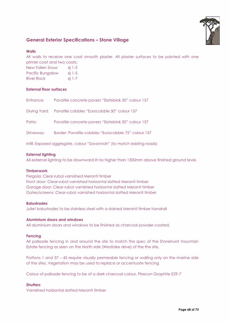
Page 68 of 73
General Exterior Specifications – Stone Village
Walls
All walls to receive one coat smooth plaster. All plaster surfaces to be painted with one
primer coat and two coats:
New Fallen Snow 6j 1-3
Pacific Bungalow 6j 1-5
River Rock 6j 1-7
External floor surfaces
Entrance: Pavatile concrete pavers “Slateblok 50” colour 157
Drying Yard: Pavatile cobbles “Eurocobble 50” colour 157
Patio: Pavatile concrete pavers “Slateblok 50” colour 157
Driveway: Border: Pavatile cobbles “Eurocobble 75” colour 157
Infill: Exposed aggregate, colour “Savannah” (to match existing roads)
External lighting
All external lighting to be downward lit no higher than 1500mm above finished ground level.
Timberwork
Pergola: Clear-rubol varnished Meranti timber
Front door: Clear-rubol varnished horizontal slatted Meranti timber
Garage door: Clear-rubol varnished horizontal slatted Meranti timber
Gates/screens: Clear-rubol varnished horizontal slatted Meranti timber
Balustrades
Juliet balustrades to be stainless steel with a stained Meranti timber handrail
Aluminium doors and windows
All aluminium doors and windows to be finished as charcoal powder-coated.
Fencing
All palisade fencing in and around the site to match the spec of the Stonehurst mountain
Estate fencing as seen on the North side (Westlake drive) of the the site.
Portions 1 and 37 – 45 require visually permeable fencing or walling only on the riverine side
of the sites. Vegetation may be used to replace or accentuate fencing
Colour of palisade fencing to be of a dark charcoal colour, Plascon Graphite E29-7
Shutters
Varnished horizontal slatted Meranti timber

Page 69 of 73
Burglar Bars
Designs should be simple, without ornate detail. All designs are subject to review by the
Design Review Committee.
No external burglar bars will be permitted
No metal security doors will be permitted externally
Rainwater Goods
To be finished as charcoal powder-coated.
Signage and Numbering
The house number is provided as part of the unit and the style may not be changed.
Swimming Pools and Water Features
Water features and swimming pools are to be designed in the style and character of the
estate. ‘Rock’ or ‘beach’ pools and artificial rock are inappropriate. Water features,
fountains and pools should be used to link the internal with the external and cool external
spaces such as courtyards and verandahs.
All pools and water features shall form part of the approval process by the DRC.
Pool fences shall conform to National building regulations, but should be constructed from
palisade to match other fencing within the development/ portion. Off-the-shelf pool fencing
shall not be allowed, unless approved by the DRC and only in an acceptable colour.
(Charcoal grey, black).
Backwash from the filter is to be dealt with in accordance with Local Authority regulations.
Swimming pool pumps must be screened from view. The position of the pump is subject to
approval by the Design Review Committee.
Outbuildings, Carports and Other Secondary Elements
“Wendy houses” and sheds are not permitted. Single or double carports are to match the
roof of the garage or main house. The supporting post and roof of the carport shall follow
the same specifications as for verandas and pergolas
Solar Heating
Solar heating is permitted as per the specifications in Amendment 4 to the Design Manual:
Solar Heating
Satellite Dishes
Satellite dishes are permitted on application to the Design Review Committee. Satellite
dishes are to be discreetly positioned so as to minimise the external effect and are to be
painted to match the colour of the home.
Landscaping
The landscaping requirements are as per item 15.2 of this Design Manual: Planting Character

Page 70 of 73
DRAFT AMENDMENT : 2011/06/01
ADDENDUM 1: SOLAR PANELS:
The following amendments to the April 2006 Rev13 guidelines are proposed.
1. Solar Heating:
The following guidelines should be followed should an owner wish to install solar water
heating, in compliance with SANS 10400 XA
1.1 Plan Submission:
A full proposal is to be submitted for the consideration of the Design Review
Committee. It is suggested that the solar panels are taken into account at the
initial plan submission stage. This will then take into account the different
roofscapes / types and how the panel is positioned so as to cause the least
possible visual impact.
The following information is to be included in each solar heating proposal:
1.2 Location
The location of the solar panel must be indicated on a roof plan and ALL
affected elevations. When choosing the location for your solar panel, please
bear the following in mind:
i. Solar panels to be hidden from view where possible
ii. Must be integrated with the design of the roof where possible
iii. To be positioned either on a:
a) flat roof,
b) between two roofs or ,
c) be screened adequately by a parapet wall
d) Directly onto the hipped or mono pitch roof itself. (please
refer to diagram 1,2 and 3 below and
e) Optimum angle 350 – 430 north
f) The panels are to be integrated with the roof, and the roof
pitch should match the angle of the panel
g) 200 to 350 loss up to 25% add additional panels or
electrician
1.3 Specifications
Kindly provide the specifications of the unit you wish to install. This includes:
i. Effective angle of elevation
ii. Tube or flat plate collector
iii. A photograph of the specific unit
1.4 Aesthetics:
The following conditions apply in terms of the aesthetics of the units:

Page 71 of 73
i. The panel must not create a reflective visible surface
ii. The entire unit must be matt black or charcoal. This includes
the frame of the panel, the stand, all pipes which service the
unit etc
1.5 Visual Impact:
The above mentioned stipulations are to ensure that the visual impact of solar
heating installations is minimised. Further to this, the following can also be
done to reduce the visual impact:
i. A screen (timber, aluminium louvers) to fully screen the entire
unit
ii. Relative to the position on the roofs: The solar panel (as far as
possible) may not form a separate unit. All installations must be
incorporated with the roof design. (Please see diagram 4
below)
Only to comply with by-law regulations - on application from DRC

Page 72 of 73
DRAFT AMENDMENT : 2012/01/01
ADDENDUM 2 – SUSTAINABLE DESIGN
RECOMMENDATIONS - (not compulsory)
A. Building Envelope
1. Insulation to cavity walls is recommended
2. Insulation to ceiling space is recommended, in addition to the ‘sisalation’ type layer
3. Acoustic / Thermal / insulated glazing is recommended, which can assist to meet
SANS 10400 XA thermal requirements, and lower noise pollution
4. Consider source & sustainability of materials selected for building (e.g. sustainable
timber)
5. Minimise air leakage to building by ensuring windows and doors seal
B. Pool
1. Rational design suggests not to use rim-flow pool due to heat and water losses
2. Swimming pool backwash collection system, for return of backwash water to the
pool is recommended to reduce water loss and wastage
3. Dark colour to capture and retain heat is recommended to reduce need for
additional heating
C. Fittings & Fixtures
1. CFL / LED lighting to be used throughout
2. Energy Efficient appliances (Green Star Ratings) should be installed
3. Hot water piping to have as short runs as possible
4. Lagging to all hot water piping to reduce heat loss
5. Motion detection switching (can be integrated with security sensors)
6. Daylight sensors to external lights with override
D. Water & Garden
1. Roof / balcony gardens are encouraged to replace lost ‘garden’ area and to
dissipate ‘heat island’ effect of building – world standard is at least 10% of building
should be covered with vegetation (window boxes, planted balconies / terraces,
wall creepers)
2. Rainwater harvesting is suggested with minimum 5000l, but recommended 10000l or
more tank. Tank to be partially buried and screened from view
3. Grey water capture and reticulation and re-use for flushing is recommended
4. Borehole / well point
5. Water wise garden
6. Underground drip-feed irrigation is recommended to reduce water wastage
7. Set flow rate on showers etc to minimum
E. Behaviour Modification
1. Replace what you displace
2. Minimise waste & recycle
3. Reduce energy use by switching off lights when rooms not in use and ‘ghost’ energy
users such as appliances left on standby
4. HWC set at maximum 60degrees

Page 73 of 73
REQUIREMENTS – (mandatory)
SANS 10400 XA - All submissions to comply with SANS 10400 XA, XA1, XA2 & XA3 and SANS
204:2011 Energy Efficiency in Buildings with respect to:
Orientation
Shading
Floors
Walls
Fenestration
Roof Assemblies
Hot Water
Ventilation
Heating
Cooling
Lighting
OTHER REQUIREMENTS
Insulation should installed below ground floor slab (insulation of some sort is required by
the SANS 10400 XA) minimum 20mm polystyrene, Iso-board or equivalent
Timer to be installed on all electrical HWC’s
Solar hot water heating where pumped must be installed with a controller with heat
sensor
Insulation / lagging of all HWC & pipes (SANS 10400 XA2)
Indoor lighting also should not create light pollution beyond the individual property
Pool heating must be solar or other non-resistance heating
Solar panels, or other energy devices such as photo voltaic panels, if used, should be
incorporated into the buildings to form part of the basic structure, should be clearly
shown and annotated, and should not extend above the roof profile i.e fitted flush with
the roof and mounted as inconspicuously as possible, preferably on north-facing roof.
Should the panels be located on a flat roof, the solar panels and structure must be
suitably screened from view. Any exposed metal structure or surround must be as per the
colour guideline for finishes. The proposal for the position, size, location and orientation of
the panels must be submitted to the Design Review Committee for approval.
use of water conservation measures in all bathroom/ablution facilities such as Low
volume shower heads / low flow taps - Max flow rate for wash hand basin taps is 6l/m
and showers 10l /min
Timer on pool pump
Pool Cover required to minimise heat loss and water evaporation
WC’s are required to be fitted with a Multi-flush system
Recycling is required, colour coded bins are recommended
Stormwater infiltration must be promoted through minimising hard paved areas and the
use of porous paving surfaces, where paving is required
Rainwater runoff from roofs must be directed into gardens and/or into rainwater tanks,
rather than directly into storm water drains. Where practical and possible in relation to
the elevation above the street. (Storm water management plan must be submitted for
approval)
The provision of rainwater tanks on site must be specified in the design plan as to the
location and screening thereof