m e m o r a n d u m - california department of transportation · state of california business,...
TRANSCRIPT

State of California Business, Transportation and Housing Agency
Department of Transportation
“Caltrans improves mobility across California”
M e m o r a n d u m Flex your power!
Be energy efficient!
To: FILE Date: November 16, 2010
File: 05-0N7000
05-SB-101-1.4/12.3
South Coast 101 HOV Lanes
From: DEPARTMENT OF TRANSPORTATION
DIVISION OF ENGINEERING SERVICES
GEOTECHNICAL SERVICES
Subject: District Preliminary Geotechnical Report: Revised Project Limits
This memo has been written to address changes to the limits of the South Coast 101 HOV
Lane Project. The project has been extended 0.6-mile to the south to include construction of
stormwater treatment facilities at the Bailard Interchange (PM 1.4). The recommendations
included in the District Preliminary Geotechnical Report (DPGR) dated September 3, 2009
are not affected by the extension of the project, nor are any additions to the report necessary
due to this change.


State of California
Department of Transportation
M e m o r a n d u m
TO: JOHN FOUCHE Senior Design Engineer Central Region Project Development Office of Design 11, Branch C
Business, Transportation and Housing Agency
Flex yoz~r power!
Be energy eflcient!
Date: September 3,2009
File: 05-ON7000 05-SB-101-2.0112.3 South Coast 10 1 HOV Lanes
~ t t n : MARCIA VIERRA Project Engineer
From: DEPARTMENT OF TRANSPORTATION DNISION OF ENGINEERING SERVICES GEOTECHNICAL SERVICES
Subject: District Preliminary Geotechnical Report
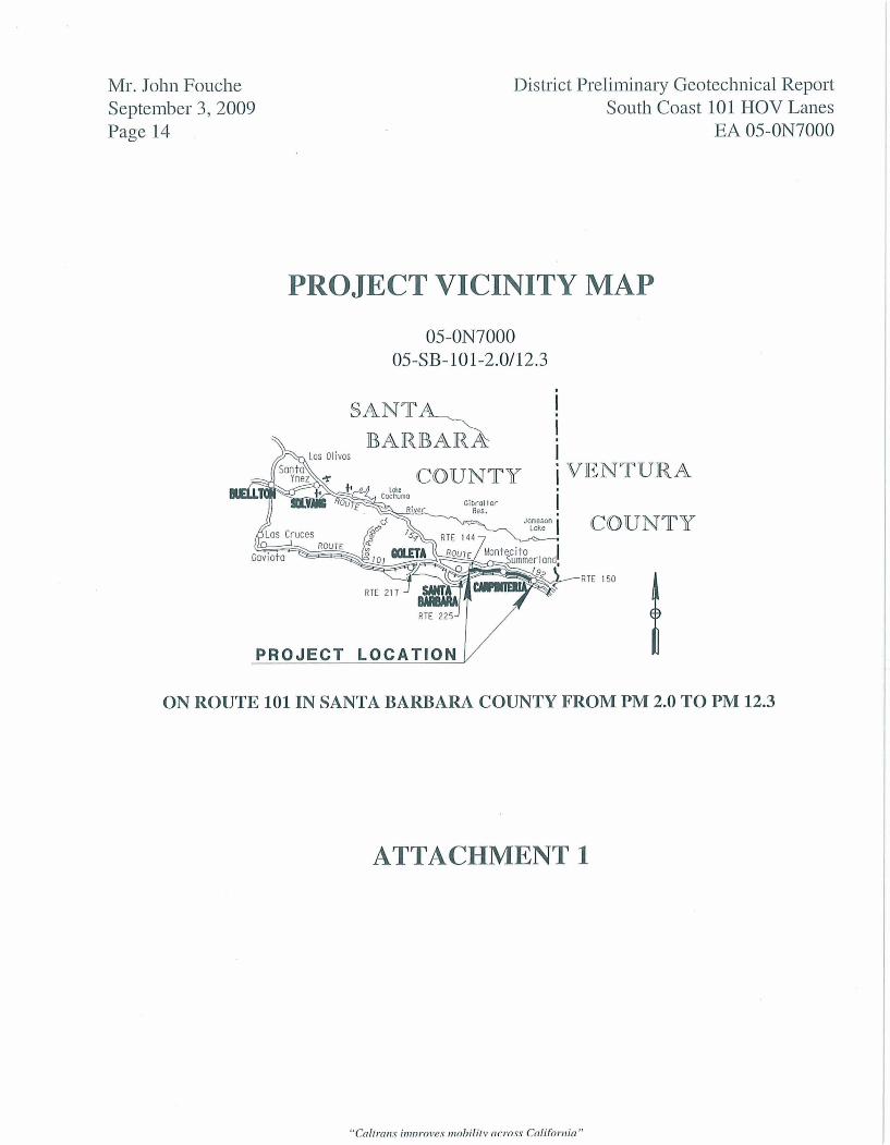
A District Preliminary Geotechnical Report (DPGR) is provided for the above referenced project per your request, dated April 1, 2009. Located in Southern Santa Barbara County, the project proposes to construct one HOV lane for each direction of travel on Route 101 between the City of Carpinteria and the City of Santa Barbara to relieve traffic congestion and improve safety along that segment of highway. A Vicinity Map showing the project location is presented as Attachment 1.
Pertinent Reports and Investigations
The following publications and references were used to assist in the evaluation of site conditions:
1. California Seismic Hazard Map 1996, Caltrans, Lalliana Mualchin, 1996.
2. 1996 California Seismic Hazard Map Report, Caltrans, Lalliana Mualchin, 1996.
3. Geologic Map of the Carpinteria Quadrangle, Santa Barbara County, California, Thomas W . Dibblee, Jr., 1986.
4. Geologic Map of the Santa Barbara Quadrangle, Santa Barbara County, California, Thomas W. Dibblee, Jr., 1986.
"Caltranv ir~lnroves mobilitv across Califonlia"
Mr. John Fouche September 3,2009 Page 2
District Preliminary Geotechnical Report South Coast 101 HOV Lanes
EA 05-ON7000
Personnel from this office have performed field reviews of the project area to determine potential geologic and geotechnical issues that may impact the construction and performance of the facility over its design life. The infomation presented herein is based on site reconnaissance and literature search, and an analysis of the proposed design. Actual conditions in the project area may differ from those assumed in this report. The information presented in this report is for planning and scoping purposes only. Additional investigations and analyses will be required to fully develop and support design recommendations.
Existing Facilities and Proposed Improvements
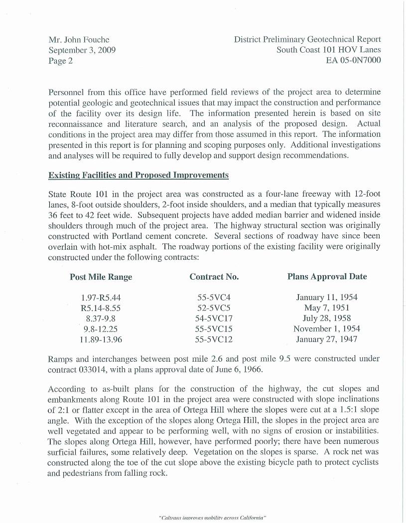
State Route 101 in the project area was constructed as a four-lane freeway with 12-foot lanes, 8-foot outside shoulders, 2-foot inside shoulders, and a median that typically measures 36 feet to 42 feet wide. Subsequent projects have added median barrier and widened inside shoulders through much of the project area. The highway structural section was originally constructed with Portland cement concrete. Several sections of roadway have since been overlain with hot-mix asphalt. The roadway portions of the existing facility were originally constructed under the following contracts:
Post Mile Range Contract No. Plans Approval Date
January 1 1, 1954 May 7,1951 July 28, 1958
November 1,1954 January 27,1947
Ramps and interchanges between post mile 2.6 and post mile 9.5 were constructed under contract 033014, with a plans approval date of June 6, 1966.
According to as-built plans for the construction of the highway, the cut slopes and embankments along Route 101 in the project area were constructed with slope inclinations of 2:l or flatter except in the area of Ortega Hill where the slopes were cut at a 1.5: 1 slope angle. With the exception of the slopes along Ortega Hill, the slopes in the project area are well vegetated and appear to be performing well, with no signs of erosion or instabilities. The slopes along Ortega Hill, however, have performed poorly; there have been numerous surficial failures, some relatively deep. Vegetation on the slopes is sparse. A rock net was constructed along the toe of the cut slope above the existing bicycle path to protect cyclists and pedestrians from falling rock.

Mr. John Fouche September 3,2009 Page 3
District Preliminary Geotechnical Report South Coast 101 HOV Lanes
EA 05-ON7000
It is proposed to construct one HOV lane for each direction of travel throughout the project limits and reconstruct two interchanges, Sheffield Drive and Cabrillo Boulevard. Alternative 2, the full build alternative, would add the HOV lanes to the outside of each roadway where there is available room within the existing right of way for landscaped medians. Alternative 3 would add an HOV lane within the existing median in both the northbound and southbound directions. Alternative 1 has slightly less planted median than Alternative 2 to protect intermittent coastal views. Roadway widening for the addition of the HOV lanes under all three alternatives will be accomplished with no modification to the existing roadway profile grade. Alternatives 2 and 3 represent the maximum and minimum construction footprints respectively, with Alternative 1 lying between
In addition to constructing the HOV lanes and reconstructing the two interchanges, all three alternatives will widen undercrossings and replace some of the existing bridges over creeks. With the exception of the interchanges at Sheffield Drive and Cabrillo Boulevard, the existing overcrossings will remain, with no modifications.
Topography
The project area is located in the Carpinteria Valley of southeastern Santa Barbara County. The Carpinteria Valley is bounded to the east, north, and northwest by the foothills of the Santa Ynez Mountains and to the south and west by the Pacific Ocean. The peaks and ridges of the adjacent foothills range from approximately 600 feet to 2,000 feet above mean sea level (MSL). Elevations of the valley floor range from sea level to approximately 130 feet above MSL. In general, the topography of the Carpinteria Valley area slopes towards the south to southwest. Average topographic gradients range from 1 percent to 2 percent within the valley except in the beach areas of the eastern portion of the valley, where uplifted marine terraces forrn steep cliffs rising 25 feet to 120 feet from the beach.
The terrain along the roadway alignment within the project limits is flat to moderately sloping. Roadway elevations in the project area range between approximately 10 feet and 180 feet above MSL. Adjacent land use is commercial, residential, agricultural, and vacant/unimproved.
Several small drainages cross the project area, draining the adjacent highlands to the north. The drainages, listed from east to west, include Carpinteria Creek, Franklin Creek, Santa Monica Creek, Arroyo Paredon, Garrapata Creek, Toro Canyon Creek, Romero Creek, San Ysidro Creek, Oak Creek, Montecito Creek, and Sycamore Canyon Creek. The drainages outlet to the Pacific Ocean along the Santa Barbara Channel.
"Caltrans ii1lnro1~e.v nlohililv across California "

Mr. John Fouche September 3,2009 Page 4
District Preliminary Geo technical Report South Coast 10 1 HOV Lanes
EA 05-ON7000
Climate
The climate in the project area is typically warm and dry in the summer and cool and wet in the winter. Daytime temperatures during the summer months are generally in the 60's to 70's ( O F ) with occasional extreme temperatures into the 100's. Nighttime summer temperatures are normally in the 50's. Winter temperatures generally have lows in the 30's to 40's with highs in the 50's to 60's. The area typically receives almost all of its rainfall between October and May with the heaviest rains occurring during the winter months. Average annual rainfall is approximately 16 inches.
The proximity of the Pacific Ocean tends to moderate the climate in the project area, while the adjacent steep mountains paralleling the coast produce a significant orographic effect. The orographic effect occurs when moist air flowing from the ocean encounters a mountain barrier and is forced up over the mountains. The air cools as it rises, and the moisture condenses and precipitates as rain or snow on the windward side of the mountain. When the moisture-depleted winds flow down the other side of the mountains, they warm and become drier. Little precipitation reaches the leeward side of the mountains. The orographic effect in conjunction with steep short watersheds occasionally results in flash flooding along the south coast of Santa Barbara County.
Regional Geology
The project area is located in the Transverse Ranges Geomorphic Province. East-west trending mountain ranges, faults, and folds characterize the Transverse Ranges Province. The Transverse Ranges Province extends from southwestern San Bernardino County westward through northern Los Angeles County and Ventura County, terminating at the Pacific Ocean near Point Argue110 in western Santa Barbara County.
The project area lies within an area designated the Santa Barbara Fold, which is located between the mountains and the ocean from east of Carpinteria to west of Goleta. It is a region of active folding that is generally comprised of west to northwest trending folds and blind reverse faults that have deformed the late Pleistocene to Holocene-aged marine terraces, terrace deposits, and alluvial fans. The localized topographic highs in the area are believed to be the result of these tectonic forces.
The rocks surrounding the Carpinteria Valley are comprised of the Quaternary-aged Casitas and Santa Barbara formations and the Tertiary-aged Monterey, Rincon, Sespe, and Coldwater Sandstone formations. Surficial deposits within the valley consist of Holocene- aged stream channel, floodplain, and alluvial fan deposits of gravels, sands, and silt.
"Caltrans inznroves lnohilitv across California"
Mr. John Fouche September 3,2009 Page 5
District Preliminary Geotechnical Report South Coast 101 HOV Lanes
EA 05-ON7000
Site Geology
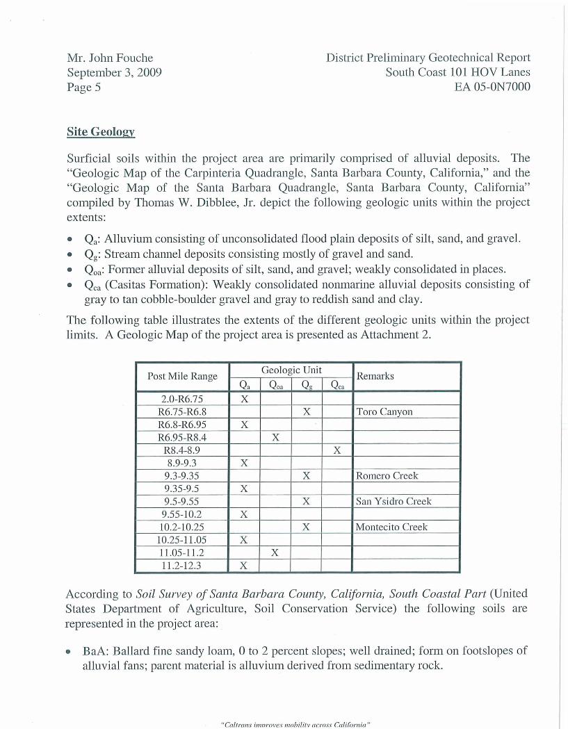
Surficial soils within the project area are primarily comprised of alluvial deposits. The "Geologic Map of the Carpinteria Quadrangle, Santa Barbara County, California," and the "Geologic Map of the Santa Barbara Quadrangle, Santa Barbara County, California" compiled by Thomas W. Dibblee, Jr. depict the following geologic units within the project extents:
Qa: Alluvium consisting of unconsolidated flood plain deposits of silt, sand, and gravel. Q,: Stream channel deposits consisting mostly of gravel and sand. Q,,: Former alluvial deposits of silt, sand, and gravel; weakly consolidated in places. Qc, (Casitas Formation): Weakly consolidated nonrnarine alluvial deposits consisting of gray to tan cobble-boulder gravel and gray to reddish sand and clay.
The following table illustrates the extents of the different geologic units within the project limits. A Geologic Map of the project area is presented as Attachment 2.
According to Soil Survey of Santa Barbara County, California, South Coastal Part (United States Department of Agriculture, Soil Conservation Service) the following soils are represented in the project area:
BaA: Ballad fine sandy loam, 0 to 2 percent slopes; well drained; form on footslopes of alluvial fans; parent material is alluvium derived from sedimentary rock.
Remarks
Toro Canyon
Romero Creek
San Ysidro Creek
Montecito Creek
Post Mile Range
2.0-R6.75 R6.75-R6.8 R6.8-R6.95 R6.95-R8.4
R8.4-8.9 8.9-9.3
9.3-9.35 9.35-9.5 9.5-9.55
9.55-10.2 10.2-10.25
10.25-1 1.05 11.05-1 1.2 11.2-12.3
"Caltrnns ir~tnroves nlol~ilitv across Califon~ia "
Geologic Unit
Qca
X
Qg
X
X
X
X
Qa
X
X
X
X
X
X
X
Qoa
X
X

Mr. John Fouche September 3,2009 Page 6
District Preliminary Geotechnical Report South Coast 101 HOV Lanes
EA 05-ON7000
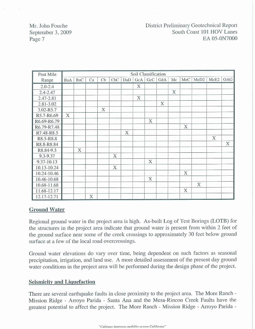
BaC: Ballard fine sandy loam, 2 to 9 percent slopes; well drained; form on footslopes of alluvial fans; parent material is alluvium derived from sedimentary rock. Ca: Camarillo fine sandy loam; poorly drained; form on 0 to 2 percent slopes on toeslopes of flood plains; parent material is alluvium derived from calcareous sedimentary rock. Cb: Camarillo Variant, fine sandy loam; poorly drained; form on 0 to 2 percent slopes on toeslopes of flood plains; parent material is alluvium derived from calcareous sedimentary rock. ChC: Cortina stony loamy sand 2 to 9 percent slopes; somewhat excessively drained; form on footslopes of alluvial fans; parent material is alluvium. DaD: Diablo clay, 9 to 15 percent slopes; well drained; form on backslopes of hills; parent material is residuum weathered from mudstone and/or soft shale. GcA: Goleta fine sandy loam, 0 to 2 percent slopes; well drained; form on toeslopes of valleys; parent material is alluvium derived from sedimentary rock. GcC: Goleta fine sandy loam, 2 to 9 percent slopes; well drained; form on footslopes of alluvial fans; parent material is alluvium derived from sedimentary rock. GdA: Goleta loam, 0 to 2 percent slopes; well drained; form on toeslopes of alluvial . fans; parent material is alluvium derived from sedimentary rock. Mc: Metz loamy sand; somewhat excessively drained; form on 0 to 2 percent slopes on footslopes of alluvial fans; parent material is coarse textured, calcareous alluvium. MeC: Milpitas-Positas fine sandy loams, 2 to 9 percent slopes; moderately well drained; form on footslopes of terraces; parent material is mixed alluvium. MeD2: Milpitas-Positas fine sandy loam, 9 to 15 percent slopes; eroded; moderately well drained; form on footslopes of terraces; parent material is mixed alluvium. MeE2: Milpitas-Positas fine sandy loam, 15 to 30 percent slopes; eroded; moderately well drained; form on footslopes of terraces; parent material is mixed alluvium. OAG: Orthents, 50 to 75 percent slopes; form on footslopes of escarpments; parent material is mixed alluvium.
The distribution of the different soil types through the project area is as follows:
"Caltrans ii11nrove.v nzobilitv across California "
Mr. John Fouche September 3,2009 Page 7
District Preliminary Geotechnical Report South Coast 101 HOV Lanes
EA 05-ON7000
Ground Water
Regional ground water in the project area is high. As-built Log of Test Borings (LOTB) for the structures in the project area indicate that ground water is present from within 2 feet of the ground surface near some of the creek crossings to approximately 30 feet below ground surface at a few of the local road overcrossings.
Ground water elevations do vary over time, being dependent on such factors as seasonal precipitation, irrigation, and land use. A more detailed assessment of the present day ground water conditions in the project area will be performed during the design phase of the project.
Seismicity and Liquefaction
There are several earthquake faults in close proximity to the project area. The More Ranch - Mission Ridge - Arroyo Parida - Santa Ana and the Mesa-Rincon Creek Faults have the greatest potential to affect the project. The More Ranch - Mission Ridge - Arroyo Parida -
"Caltra~u ii11nrove.v nlnbilitv across Califnrnia"

Mr. John Fouche September 3,2009 Page 8
District Preliminary Geotechnical Report South Coast 101 HOV Lanes
EA 05-ON7000
Santa Ana Fault, a normal-oblique fault, trends roughly west to east, and lies to the north of Route 101 in the project area. The distance from the highway to the Fault ranges from as close as 0.84-mile at milepost R6.0 to as far away as 2.27 miles at milepost 2.0. According to the Cal$ornia Seismic Hazard Map 1996 (Caltrans, 1996), the maximum credible Moment Magnitude for an earthquake on the More Ranch - Mission Ridge - Arroyo Parida - Santa Ana Fault is 7.50. According to the Caltrans adopted Mualchin peak acceleration curves, the Fault is considered capable of generating horizontal accelerations of up to 0.7g in the project area.
The Mesa-Rincon Creek Fault also trends roughly west to east. Its style of faulting is not known. The Mesa-Rincon Creek Fault lies approximately 0.98-mile to the north of Route 101 at milepost 2.0, crosses the highway at about milepost 4.36, dips as far as 1.7 miles south of the highway alignment near milepost 8.6, and crosses Route 101 again at approximately milepost 13.8. According to the California Seismic Hazard Map 1996 (Caltrans, 1996), the maximum credible Moment Magnitude for an earthquake on the Mesa- Rincon Creek Fault is 7.00. According to the Caltrans adopted Mualchin peak acceleration curves, the Fault is considered capable of generating horizontal accelerations of up to 0.6g in the project area.
According to the California Seismic Hazard Map 1996 (Caltrans, 1996) the Mesa-Rincon Creek Fault crosses Route 101 within the easterly project limits. Thus, there is potential for ground rupture and displacement of the highway surface due to movement of the Fault. The slip rate along the Mesa-Rincon Creek Fault is estimated to be approximately 0.08 inches per year (California Geologic Survey).
Liquefaction is the sudden loss of soil strength due to a rapid increase in soil pore water pressures resulting from seismic ground shaking. Liquefaction potential is dependent on such factors as soil type and relative density of the soil, depth to ground water, and degree of seismic shaking. Loose, cohesionless soils that may become saturated due to a high water table may liquefy during an earthquake. Embankments founded on liquefiable soils may be subject to slope instability and settlement during an earthquake event. Earth-retaining structures may settle or overturn should the soils beneath them liquefy.
For liquefaction to occur, three elements in combination are necessary: loose granular soils within 30 feet of the ground surface, saturated soil conditions, and strong ground shaking. Liquefaction potential may be significant in the project area; much of the project is underlain by unconsolidated to weakly consolidated alluvial soils, ground water is present at shallow depths in much of the project area, and the likelihood for strong ground shaking is high due to the close proximity of potentially active earthquake faults to the project area.
"Caltrans itrtnroves nrohilitv across Califonlia"

Mr. John Fouche September 3,2009 Page 9
District Preliminary Geotechnical Report South Coast 101 HOV Lanes
EA 05-ON7000
Corrosion
Representative soil and ground water samples from the project area will be tested for corrosion potential during the geotechnical investigation for this project. However, segments of the project area are considered corrosive based solely on their close proximity (within 1000 feet) to the Pacific Ocean.
Hazardous Materials
Due to the many years of severe traffic congestion in the project area, it is very likely that high concentrations of aerially deposited lead (ADL) are present in the surficial soils adjacent to the highway. The Department's Environmental Branch will provide a more detailed assessment of the likelihood of encountering ADL and other hazardous materials within the project limits.
Preliminary Recommendations
Slopes
It is recommended that all new cut slopes be excavated with slope inclinations of 2:l or flatter. Paved top-of-cut ditches should be provided to minimize the potential for erosion where there are large off-site drainage areas draining toward the slopes.
New embankments and embankment widenings should be constructed with slope inclinations of 2: 1 or flatter. Steeper slopes, up to 1.5: 1, are feasible if the embankments are constructed of select material conforming to the following specifications:
Maximum Sand Equivalent = 50 Maximum Plasticity Index = 20 Minimum Plasticity Index = 12
If select material is not available from local sources, it is recommended that the steeper embankments be constructed with geosynthetic reinforcement. Slopes as steep as 1:l are feasible using geosynthetic reinforcement. Earth retaining structures should also be considered where right of way constraints limit the allowable footprint of embankments.
Erosion of the new slopes is a serious concern, and an aggressive revegetation plan should be implemented as part of the design. The District Landscape Architect should be consulted for recommendations regarding plant selection and proper application of erosion control materials.
"Caltmns i~imroves n~ohilitv across Califontic?"

Mr. John Fouche September 3,2009 Page 10
District Preliminary Geotechnical Report South Coast 101 HOV Lanes
EA 05-ON7000
Retaining Walls
Topic 210, "Reinforced Earth Slopes and Earth Retaining Systems," of Caltrans' Highway Design Manual provides a good overview of the different types of earth retaining systems that may be considered, and their preferred applications. State designed earth retaining systems that utilize Standard Plans are usually a good starting point for any design because they require no Structures Design involvement. Standard Plan walls, however, are not applicable to all situations, nor are they necessarily the most cost effective alternative. Loading conditions and foundation requirements are shown on the plans. The District Project Engineer (PE) should confirm that the required loading conditions are covered by the Standard Plans. He should then request a foundation investigation from Geotechnical Design for each location where a retaining wall is being considered.
It is very likely that the foundation requirements of the Standard Plans will not be met at some locations underlain by geologic unit Q,. The unconsolidated flood plain deposits are not expected to have adequate bearing capacity to support the foundation loads. Furthermore, total and differential settlement will likely exceed allowable limits. Site- specific investigations will be necessary to verify or refute this assessment.
For embankments, mechanically Stabilized Earth (MSE) retaining walls or Standard Plan Type I retaining walls on pile foundations will probably be viable alternatives to Standard Plan retaining walls on spread footings where the foundation soils will not provide adequate bearing capacity. In cut situations, soldier pile walls or soil nail walls may be preferred over Standard Plan retaining walls because they are better suited to top-down construction techniques.
Sound Walls
Standard Plan sound walls can be founded on spread footings, trench footings, Cast-in- Drilled-Hole (CIDH) concrete piles, or on driven displacement or non-displacement piles. Spread footings are probably the least expensive foundation type and the most easily constructed, but have a couple of serious drawbacks. The most overlooked drawback is their space requirement; the footing extends beyond the front and the back of the wall up to 2'-5". Sound walls are typically constructed as close to the right of way line as possible, so if the footing extends behind the wall a strip of land remains between the back of wall and the right of way that must be maintained, but is too narrow to be usable.
The other potential problem with spread footings is that the maximum toe pressure from the footing may exceed the bearing capacity of the in situ foundation soil. Much of the project
"Caltranv it11nrove.v nlobilitv across Califontia"
Mr. John Fouche September 3,2009 Page 11
District Preliminary Geotechnical Report South Coast 101 HOV Lanes
EA 05-ON7000
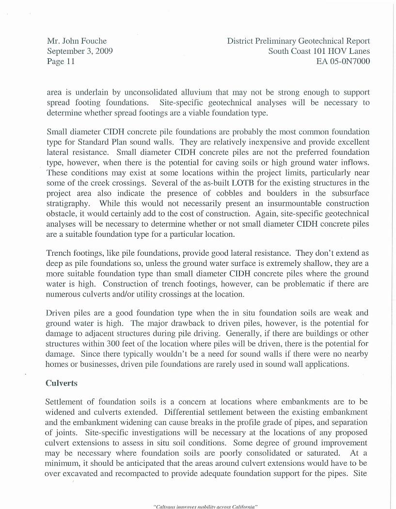
area is underlain by unconsolidated alluvium that may not be strong enough to support spread footing foundations. Site-specific geotechnical analyses will be necessary to determine whether spread footings are a viable foundation type.
Small diameter CIDH concrete pile foundations are probably the most common foundation type for Standard Plan sound walls. They are relatively inexpensive and provide excellent lateral resistance. Small diameter CIDH concrete piles are not the preferred foundation type, however, when there is the potential for caving soils or high ground water inflows. These conditions may exist at some locations within the project limits, particularly near some of the creek crossings. Several of the as-built LOTB for the existing structures in the project area also indicate the presence of cobbles and boulders in the subsurface stratigraphy. While this would not necessarily present an insurmountable construction obstacle, it would certainly add to the cost of construction. Again, site-specific geotechnical analyses will be necessary to determine whether or not small diameter CIDH concrete piles are a suitable foundation type for a particular location.
Trench footings, like pile foundations, provide good lateral resistance. They don't extend as deep as pile foundations so, unless the ground water surface is extremely shallow, they are a more suitable foundation type than small diameter CIDH concrete piles where the ground water is high. Construction of trench footings, however, can be problematic if there are numerous culverts andfor utility crossings at the location.
Driven piles are a good foundation type when the in situ foundation soils are weak and ground water is high. The major drawback to driven piles, however, is the potential for damage to adjacent structures during pile driving. Generally, if there are buildings or other structures within 300 feet of the location where piles will be driven, there is the potential for damage. Since there typically wouldn't be a need for sound walls if there were no nearby homes or businesses, driven pile foundations are rarely used in sound wall applications.
Culverts
Settlement of foundation soils is a concern at locations where embankments are to be widened and culverts extended. Differential settlement between the existing embankment and the embankment widening can cause breaks in the profile grade of pipes, and separation of joints. Site-specific investigations will be necessary at the locations of any proposed culvert extensions to assess in situ soil conditions. Some degree of ground improvement may be necessary where foundation soils are poorly consolidated or saturated. At a minimum, it should be anticipated that the areas around culvert extensions would have to be over excavated and recompacted to provide adequate foundation support for the pipes. Site
I

Mr. John Fouche September 3,2009 Page 12
District Preliminary Geotechnical Report South Coast 101 HOV Lanes
EA 05-ON7000
investigations will also be necessary where it is proposed to install culverts utilizing the jack and bore method of installation. As-built LOTB for some of the existing structures within the project area indicate the presence of cobbles and boulders in the subsurface stratigraphy. These ground conditions can eliminate jacking and boring as a viable construction alternative.
Seepage
It is proposed to lower the profile grade of the Los Patos Way off ramp from southbound Route 101 to increase the vertical clearance under the Union Pacific Railroad Bridge, bridge No. 51-235. It is very likely that ground water seepage will be a concern to the construction and maintenance of the lowered roadway. According to topographic mapping of the area, the existing ground elevation on Los Patos Way in the area of the bridge is approximately 11 feet above MSL. The existing vertical clearance under the bridge is only 12 feet, so it is probable that the profile grade of Los Patos Way would be lowered at least 3 feet. That would place the profile grade elevation at about 8 feet above MSL. The ground water elevation at the Cabrillo Boulevard UP, approximately 1400 feet east of Los Patos Way, was reported to be 15 feet to 19 feet above MSL during the 1953 subsurface investigation for the design of that bridge. The subsurface investigation for the design of Sound Wall 1 on the Milpas to Hot Springs Operational Improvements project (contract No. 05-447804), currently under construction, encountered ground water at elevations between 6 feet and 9 feet above MSL. Sound Wall 1 lies approximately 1000 feet west of the Union Pacific Railroad Bridge. These ground water observations suggest that lowering Los Patos Way would put portions of the roadway below the ground water surface.
Methods for construction of roadway sections below ground water include dewatering by pumping or construction of "boat sections." Boat sections are like swimming pools with water on the outside rather than the inside. The sections are constructed with reinforced concrete bottoms and sides. Pile foundations resist the buoyant effect of the ground water on the structure.
Boat sections are generally preferred over pumping because they are a passive method of ground water management. Pumping, on the other hand, is a 2417 operation that involves utility costs and constant maintenance. Furthermore, ground water often contains contaminants that must be removed before the water can be discharged into a waterway.
"Caltrans inznroves ~ltohilitv acros.v Califonria"

Mr. John Fouche September 3,2009 Page 13
District Preliminary Geotechnical Report South Coast 10 1 HOV Lanes
EA 05-ON7000
Closure
A Geotechnical Design Report (GDR) should be requested from this office after all of the alternatives have been considered and a preferred alternative has been selected. Layouts, profiles, and cross sections will be required to complete the report. The GDR will provide final design recommendations for the proposed project based upon a more thorough site investigation. Analyses to be performed for the preparation of the GDR include slope stability modeling (static and dynamic) of proposed cut and fill slopes, and embankment settlement calculations. Designs will be provided for geosynthetic-reinforced embankments if embankment slopes steeper than 2: 1 are to be included in the project.
Individual Foundation Reports (FR) should be requested for all retaining walls and sound walls that will be incorporated into the project. Advance Planning Studies (APS) should be requested from Structures Design for any proposed non-standard earth retaining structures or sound walls.
If you have any questions or comments, please contact Dan Appelbaum at (805) 549-3745 or Mike Finegan at (805) 549-3194.
DANIEL L. APPELBAUM, PE Transportation Engineer Geotechnical Design - North Branch D
Roy Bibbens 1 GDN File Job File I Branch D Records
Supervised by,
MICHAEL S. F&~&AN, PE, Chief Geotechnical Design - North Branch D
"Caltra~zs bmrove.~ mohilitv across California"
Mr. John Fouche September 3,2009 Page 14
District Preliminary Geotechnical Report South Coast 101 HOV Lanes
EA 05-ON7000
PROJECT VICINITY MAP
b ~ a s Cruces
PROJECT LOCATION I/
VENTURA
COUNTY
ON ROUTE 101 IN SANTA BARBARA COUNTY FROM PM 2.0 TO PM 12.3
ATTACHMENT 1
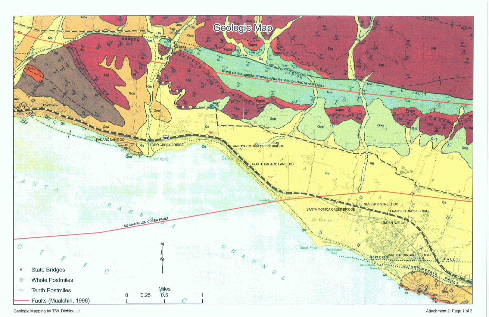
Geologic Mapping by T.W. Dibblee, Jr. Attachment 2: Page 1 of 2

&. re- ~-q:&: -;: & ., . .
Geologic Mapping by T.W. Dibblee, Jr. Attachment 2 : Page 2 of 2