lumber dryer owner's manual kiln construction guide troubleshooting
TRANSCRIPT

Page 1 of 36
Drawing : - TPC230 Issue : - 4 Date : - 10/12/13
LUMBER DRYER OWNER’S MANUAL
KILN CONSTRUCTION GUIDE TROUBLESHOOTING GUIDE
LD800
www.eipl.co.uk
Page 2 of 36
Drawing : - TPC230 Issue : - 4 Date : - 10/12/13
EBAC LD800 TABLE OF CONTENTS
PAGE
Introduction --------------------------------------------------------------- 3 Lumber Drying Principles ---------------------------------------------- 4 Unpacking ------------------------------------------------------------------ 6 Contents --------------------------------------------------------------------- 6 KILN DESIGN & CONSTRUCTION: Dryer Capacities ---------------------------------------------------------- 7 Kiln Chamber -------------------------------------------------------------- 8 Lumber Stack Size ------------------------------------------------------ 9 Chamber Interior Dimensions ----------------------------------------- 10 Choosing Proper Insulation Thickness ------------------------------ 10 Example Kiln Sizes ------------------------------------------------------- 11 Construction of Chamber ---------------------------------------------- 12 Finishing Details of the Chamber ------------------------------------- 12 INSTALLATION & TESTING: Wiring Requirement ------------------------------------------------------ 18 Testing for Proper Operation ------------------------------------------ 18 DRYING LUMBER: Preparation of the Lumber Stack ------------------------------------ 19 Kiln Operating Instructions -------------------------------------------- 20 Dryer Control Settings --------------------------------------------------- 22 Additional Notes On Lumber Drying --------------------------------- 23 APPENDIXES: Oven Dry Method for Determining Equilibrium Moisture Content ---------------------------------------------------------- 24 Troubleshooting ----------------------------------------------------------- 26 Drawings & Specifications ---------------------------------------------- 29

Page 3 of 36
Drawing : - TPC230 Issue : - 4 Date : - 10/12/13
INTRODUCTION You have probably never seriously considered kiln drying your own lumber before, believing it to be too expensive or too complicated to undertake on a small scale. Prior to the introduction of the Ebac Small Scale Lumber Dryers this was true. Kiln drying was for the world of specialists: a confusing maze of kiln schedules, sampling techniques, relative humilities and complex controls – hardly inviting to the small woodworking business which merely wanted to be sure of a regular supply of quality wood at a reliable and consistent moisture content. Ebac Small Scale Lumber Dryers have changed all that. Whether yours is a one-man business or somewhat larger, whether you are in the woodworking business or woodworking is just your hobby, you do not need any previous experience with drying. As well as being simple to install and operate, Ebac dryers are quiet and cause no pollution. The Lumber Dryers themselves are installed in easily made chambers of the appropriate size. This manual has been designed to guide you through the problems of choosing the correct size of wood dryer for your needs, constructing a suitable chamber and operating the kiln to obtain maximum output of wood. Use it carefully and thoroughly and you will quickly find out everything that you need to know. For further information and details of constructions and applications not covered, we will be pleased to offer advice and assistance as required. Please do not hesitate to contact us.

Page 4 of 36
Drawing : - TPC230 Issue : - 4 Date : - 10/12/13
LUMBER DRYING PRINCIPLES When lumber is being dried, the rate of moisture evaporation is dependent on the difference between the vapor pressure of the wet wood and the vapor pressure of the air. When the vapor pressures have equalized, no further drying occurs. This is the point at which the equilibrium moisture content of the wood has been reached. (See Figure 1). One way of increasing this vapor pressure difference and encouraging rapid drying, is to heat the wood and increase its vapor pressure. Essentially this is what conventional steam kilns do.
EMC at 68°F (20°C)
(Figure 1)
Another way of increasing the difference between the vapor pressure of the air and that of the wood is to lower the vapor pressure of the air. This is what Ebac dryers do: encourage evaporation by removing moisture from the air surrounding the wood. As damp air is drawn into the machine (see Figure 2) water condenses onto a refrigerated coil. The water is drained off and the dried air is re-warmed with the heat from the condenser coil. The air is re-circulated through the lumber stack, causing more evaporation. Moisture-laden hot air is not simply vented into the atmosphere as in energy wasteful steam kilns; this results in efficient operation.

Page 5 of 36
Drawing : - TPC230 Issue : - 4 Date : - 10/12/13
SIMPLIFIED SCHEMATIC DIAGRAM OF LUMBER DRYER COMPONENTS
Figure 2
Though the fastest drying is achieved at high temperature, the risks of degrade in the wood, particularly hardwood, increases at high temperature. The general rule is that the lower the temperature the better the quality. Ebac dryers are designed to operate in the temperature range, which is the best compromise between speed and quality – about 140°F (60°C) and lower. Drying at these temperatures insures that the wood is of the highest quality, and that the equipment is reliable.

Page 6 of 36
Drawing : - TPC230 Issue : - 4 Date : - 10/12/13
UNPACKING
Upon receipt of your LD800, carefully inspect the shipping container and its contents for any damage. If damage is discovered, contact the Service Department for instructions.
CONTENTS Your LD800 shipment consists of the following items:
1. LD800 Lumber Dryer 2. Discharge Tubing 3. Styrofoam Baffle (2 Sections)
CAUATION: DO NOT throw away or damage the Styrofoam pieces. They will be used inside your kiln.
Page 7 of 36
Drawing : - TPC230 Issue : - 4 Date : - 10/12/13
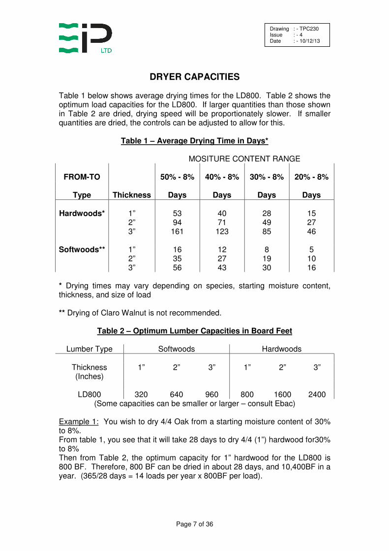
DRYER CAPACITIES
Table 1 below shows average drying times for the LD800. Table 2 shows the optimum load capacities for the LD800. If larger quantities than those shown in Table 2 are dried, drying speed will be proportionately slower. If smaller quantities are dried, the controls can be adjusted to allow for this.
Table 1 – Average Drying Time in Days*
MOSITURE CONTENT RANGE
FROM-TO 50% - 8% 40% - 8% 30% - 8% 20% - 8%
Type Thickness Days Days Days Days
Hardwoods* 1” 2” 3”
53 94
161
40 71
123
28 49 85
15 27 46
Softwoods** 1”
2” 3”
16 35 56
12 27 43
8 19 30
5 10 16
* Drying times may vary depending on species, starting moisture content, thickness, and size of load ** Drying of Claro Walnut is not recommended.
Table 2 – Optimum Lumber Capacities in Board Feet
Lumber Type Softwoods Hardwoods
Thickness (Inches)
1” 2” 3” 1” 2” 3”
LD800 320 640 960 800 1600 2400
(Some capacities can be smaller or larger – consult Ebac)
Example 1: You wish to dry 4/4 Oak from a starting moisture content of 30% to 8%. From table 1, you see that it will take 28 days to dry 4/4 (1”) hardwood for30% to 8% Then from Table 2, the optimum capacity for 1” hardwood for the LD800 is 800 BF. Therefore, 800 BF can be dried in about 28 days, and 10,400BF in a year. (365/28 days = 14 loads per year x 800BF per load).

Page 8 of 36
Drawing : - TPC230 Issue : - 4 Date : - 10/12/13
KILN CHAMBER
LUMBER STACK SIZE
The first step in determining your kiln chamber size is to determine the most suitable lumber stack size (or configuration) for your purposes. This will depend primarily on the longest length board to be dried. Normally, the length of the stack will be equal to the length of the longest board. If your lumber is in short lengths (i.e.: approximately 3 feet), then the stack length should be a multiple of these short lengths. The width and height of the stack can be adjusted to suit your conditions. The “stack” may actually be made up of two or more smaller stacks, or packs. In order to allow air-flow through the lumber stack each “layer” must be separated from that below by a spacer or “sticker” of ¾ to 1” thickness. The air spaces thus created must be included in the overall stack height when calculating volume. Use this procedure to determine stack height and width: First, select an appropriate width and then calculate stack height including stickers. If this calculated height would result in an awkward height to width, select a new width. See Example 2 which follows. Example 2: Desired kiln capacity is 800 BF of 12 hardwood, and the longest board is 12 feet. Add 10% to the lumber quantity to allow for non-uniformity in the stack. If that stack width is 3 feet, then each layer of lumber would contain: BF per layer = 12’ x 3’ x 12 thick = 36 BF Layers required = 800 BF x 1.1 = 24.4 or 25 layers 36 BF/Layers Each layer is 1” + ¾” sticker – 1 ¾” high Stack height – 25 layers x 1 ¾” – 43 ¾” high

Page 9 of 36
Drawing : - TPC230 Issue : - 4 Date : - 10/12/13
CHAMBER INTERIOR DIMENSIONS
Having calculated the stack size, it is now possible to calculate the appropriate internal dimensions of the drying chamber. This is done by adding the required additional space around the stack for the dryer and fans as well as for good air circulation. Suggested additional space is: Length: 16” Width: 14” Height: 12” Example 3: Using information from Example 2, where the stack size was 12’ land and 3’ wide and 43 ¾” high, we can find required internal dimensions. Length: 12’ + 16” = 13’ 4” Width: 3’ + 14” = 4’ 2” Height: 43 ¾” + 12” = 55 ¾” Minimum Interior Dimensions 13’ 4” (L) x 4’ 2” (W) x 55 ¾” (H)

Page 10 of 36
Drawing : - TPC230 Issue : - 4 Date : - 10/12/13
CHOOSING PROPER INSULATION THICKNESS
The wall thickness (insulation) is very important and is related to the size (surface area) or the chamber. After adding the required internal clearances to the stack size, the internal dimensions are known, and the approximate chamber surface area can be calculated. Table 3 show the recommended thickness of insulation (wall thickness) in relation to the total surface of the walls, ceilings and floor of the chamber. To determine wall (insulation) thickness we must now calculate approximate surface area of the chamber. Example: Kiln Dimensions: 5’ x 3 ½’ x 14’ (H x W x L) Ends: 3 ½’ x 5’ x 2 pieces = 35 sq. ft Top and Bottom: 3 ½’ x 14’ x 2 pieces = 98 sq. ft Front and Back: 5’ x 14’ x 2 pieces = 140 sq. ft 273 sq. ft surface area From Table 3, R-11 value is appropriate. Final outside dimensions can now be determined.
Table 3 – Thickness of Insulation
Surface Area of Chamber
In Sq. Ft 100 200 300 400 500
Optimum R-Value 5 8 11 16 21
Fiberglass Insulation Blue Styrofoam R-11 = 3 ½” R-10 = 6” R-7 = 1” The thicknesses in the table are optimum for year-round operation. If you wish to increase efficiency during the winter in cold climates, increase thickness by about 50% and remove extra insulation during the summer. This extra insulation may cause the kiln to overheat in the summer.

Page 11 of 36
Drawing : - TPC230 Issue : - 4 Date : - 10/12/13
EXAMPLE KILN SIZES
If you would rather not design the dimensions of your kiln, simply choose the best size for you operation from Table 4. All of the kiln dimensions shown below are exterior dimensions. The load sizes refer to 1” hardwood with ¾” stickers, and all wall thicknesses and air spaces have been added in.
Table 4 – Example Kiln Sizes (Height x Width x Length)
6’ Lumber 7’ x 6’ x 8’ = 800 BF 6’ x 6’ x 8’ = 600 BF
8’ Lumber 6’ x 6’ x 10’ = 800 BF 5’ x 6’ x 10’ = 600 BF
10’ Lumber 5’ x 6’ x 12’ = 800 BF 5’ x 5’ x 12’ = 600 BF
12’ Lumber 5 ½’ x 5’ x 14’ = 800 BF 4 ½’ x 5’ x 14’ = 600 BF
14’ Lumber 5’ x 5’ x 16’ = 800 BF 4 ½’ x 4 ½’ x 16’ = 600 BF
16’ Lumber 4 ½’ x 5’ x 18’ = 800 BF 4’ x 5’ x 18’ – 600 BF

Page 12 of 36
Drawing : - TPC230 Issue : - 4 Date : - 10/12/13
CONSTRUCTION OF CHAMBER
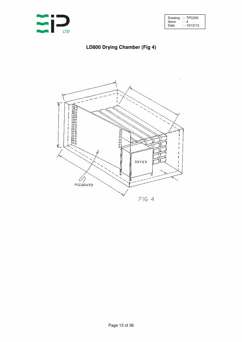
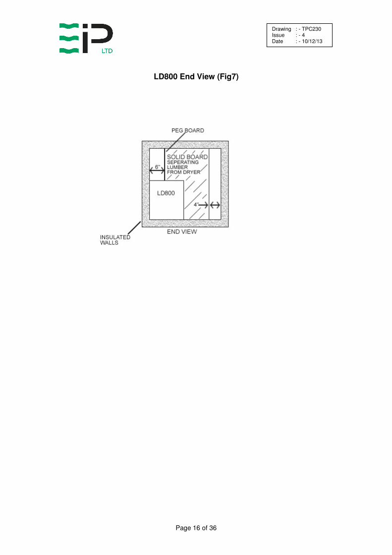
The most important point is to install a continuous vapor barrier (Plastic Film) inside the frame. The walls, floor and ceiling should be made of frame construction filled with insulation (Styrofoam, fiberglass, etc.). The exterior surface should be ¼” to ½” CDX Plywood. Line the interior with polythene film and use tape to close up gaps and cover tack heads. A good material to use over the film is ¼” tempered hardwood (exterior grade). In order to provide support for walking, ½” plywood is recommended for the floor. Use a minimum number of nails to minimize the number of holes in the plastic film. Again, put the tape over the nail heads in the hardboard. Plastic package sealing tape works well. The LD800 kiln requires an air plenum chamber to help distribute the air throughout the lumber stack. The surface of the plenum facing the lumber stack should be 1/8” or ¼” tempered pegboard for the air to pass through. Far all dry kilns, baffles or curtains should be provided above and to the side of the stack to force the air flow through the lumber stack, not around. (Refer to Figures 4-8). The LD800 chamber should be placed on a 4” x 4” stringers, on dry ground, preferably within a warehouse or workshop. If space limitations dictate that the chamber should be located outdoors, then it should be protected from rain, snow and direct rays of the sun by means of a roof or separate canopy.
FINISHING DETAILS OF THE CHAMBER
When the basic construction is complete, it is necessary to bore a 2” hole in the wall adjacent to the dryer through which to pass a drain hose and power cord(s) from the dryer. It is very important that the hole in the wall is bored below the level of the water outlet of the dryer – otherwise water will back up in the hose and flood the interior of the chamber. Use rope caulking or similar material to seal the hole after the hose and power cord are installed to prevent heat loss from the chamber.
Page 13 of 36
Drawing : - TPC230 Issue : - 4 Date : - 10/12/13
LD800 Drying Chamber (Fig 4)

Page 14 of 36
Drawing : - TPC230 Issue : - 4 Date : - 10/12/13
Lumber Stack Side View (Fig 5)

Page 15 of 36
Drawing : - TPC230 Issue : - 4 Date : - 10/12/13
LD800 Cutout detail in Plenum (Fig 6)
Page 16 of 36
Drawing : - TPC230 Issue : - 4 Date : - 10/12/13
LD800 End View (Fig7)

Page 17 of 36
Drawing : - TPC230 Issue : - 4 Date : - 10/12/13
LD800 Top View (Fig 8)

Page 18 of 36
Drawing : - TPC230 Issue : - 4 Date : - 10/12/13
INSTALLATION AND TESTING
WIRING REQUIREMENT
All wiring should be carried out by a competent electrical contractor in accordance with local regulations. Check the voltage at the power supply to ensure correct voltage is 100 Volt + 10%, 1 Phase, 60 Hz. The LD800 must be plugged into a suitably fused 110 Volt outlet.
TESTING FOR PROPER INSTALLATION
Remove the left side panel by removing the four retaining screws. This will expose the evaporator coils and drain tray.
Adjust the temperature control and the drying control on the STC1 Controller to the minimum setting. Plug the LD800 power cord into the 110 Volt, 1 Phase, 60 Hz receptacle. (Insure that the power to the receptacle has been achieved). The fan in the LD800 will start to rotate immediately. Set the STC1 drying control to C and the temperature control to 45ºC. The above setting will result in the following:
1. The heating element in the LD800 will be switched on. 2. After a 10 minute delay, the compressor will start to run.
When the compressor has been running for 10 minutes the bare copper coils above the drain tray should be covered with either frost or condensation. (The last two or three turns on the rear coils may not have frost or condensation because the refrigerant is picking up superheat for the return to the compressor). After insuring proper operation of the LD800, disconnect the power cord and reinstall the left side panel.
Warning: Do not operate the LD800 for an extended period of time with the covers removed. This will cause improper operation of the machine and may cause damage to the components.

Page 19 of 36
Drawing : - TPC230 Issue : - 4 Date : - 10/12/13
DRYING LUMBER
PREPERATION OF THE LUMBER STACK
The best lumber drying results are obtained when the loads of lumber are of the same species, quality, thickness and initial moisture content. However, this is not always possible, particularly in small scale operations. In such situations the drying procedure should follow the slowest wood in the load – i.e., the hardest, thickest, or wettest boards. The layers of lumber are separated by stickers. The thickness of the stickers is determined by the thickness of the lumber most commonly being dried. Stickers of ¾” are generally used with boards up to 1 ½” and stickers of 1” for boards thicker than 1 ½”. In practice, one set of stickers can be used in a kiln no matter what the lumber thickness. The layers of stickers should be placed directly above each other to prevent distortion of the boards during drying. The space between columns of stickers should be approximately 18” to 30” for board thickness up to 1 ½” and 24” to 48” for board thickness’ greater than 1 ½”. Put a column of stickers at each end of the stack to support the ends and help reduce checking. The important consideration is that the boards do not sag between rows of stickers. Gaps in the stack cross-section are reduced be using boards of the same length, which otherwise would result in a non-uniform circulation at these spots. It is also important for good air circulation to fill the chamber to full capacity. If this is not possible, any gaps/spaces should be blocked with baffles so that the air passes through the stack and not around it. Before placing the lumber in the chamber, the initial moisture content of the wettest boards should be measured by means of an electronic moisture meter or the oven dry method (see Appendix 1). Ebac can provide a suitable moisture meter system to meet your needs at an additional cost.

Page 20 of 36
Drawing : - TPC230 Issue : - 4 Date : - 10/12/13
KILN OPERATING INSTRUCTIONS
1. Connect the main power cable to a suitable power supply. 2. Select the appropriate setting from the relevant drying control schedule
as shown in Table 5. Settings are based on the amount and type of lumber to be dried.
3. Set the temperature control on the STC1 Controller at the lower of the following:
a. 5ºC higher than the kiln temperature (shown on the digital
display on the controller); or b. The maximum chamber temperature from the graph below.
The temperature should be increased by 5ºC (9ºF) every 24 hours, but must NEVER exceed the temperatures shown on the graph below. If the temperature does not increase in accordance with the temperature control knob adjustments, (i.e., 24 hours after an increase of 5ºC the temperature has risen a low amount, e.g. 3ºC), this indicates that the heater is operating continuously but the temperature rise has not been achieved. This can be caused by the volume of wood being heated, cold weather conditions, or inadequate insulation. The next temperature setting should be 5ºC above the kiln temperature as displayed on the temperature meter.
MAXIMUM SELECTED TEMPERATURE
50
45
40
Temperature
ºC 35
30
40% 30% 20% 10%
Moisture Content of Wood
Warning: If the table calls for a setting of “C” (Continuous), set the drying control at 90% at first, until the temperature reaches 35ºC (95ºF). Position “C” can then be selected.
Below 35ºC the dehumidifier requires the 10% off-time to defrost the ice formed on the heat exchanger (cold coil). Above 35ºC (95ºF), the condensation does not freeze, but drips continuously into the drain tray and out the drainage hose.

Page 21 of 36
Drawing : - TPC230 Issue : - 4 Date : - 10/12/13
Two things are very important:
a) THE RATE OF TEMPERATURE INCREASE MUST NOT BE MORE THAN 5ºC (9ºF) PER DAY.
Never set the thermostat more than 5ºC (9ºF) above the present kiln temperature. Rapid temperature increases cause the relative humidity to suddenly drop leading to surface and end checking of the lumber.
b) THE KILN TEMPERATURE MUST NOT EXCEED THAT WHICH IS
SAFE FOR THE MOISTURE CONTENT OF THE LUMBER.
The maximum chamber temperature, shown on the preceding graph, indicates the maximum safe kiln temperature at every stage of the drying.
The temperature graph implies that you must measure the lumber moisture content each time before increasing the temperature when operating above 35ºC (95ºF). To determine if drying cycle is complete, the lumber moisture content must be actually measured using a moisture meter or the oven dry method.
4. To check that the drying rate is correct, allow the kiln about 3 days to
stabilize after starting and then measure the water extracted during a 24 hour period. As the wood dries, the drying control and thermostat may be increased to maintain the water extraction rate.
COMPLETING THE RUN: When the drying cycle is complete, leave the wood for approximately 24 hours in the chamber with the Drying Control setting reduced to 10% and the thermostat reduced to its lowest setting. This allows the residual moisture within the wood to become more evenly distributed.

Page 22 of 36
Drawing : - TPC230 Issue : - 4 Date : - 10/12/13
Table 5 Drying Control Settings
LD800 LUMBER DRYER
CHAMBER LOAD – SOFT WOODS
Drying Control Setting
4/4 25mm 8/4 50mm 12/4 75mm
Board Ft Cu Mtrs Board Ft Cu Mtrs Board Ft Cu Mtrs C
85
70
55
35
320
255
190
130
65
0.8
0.6
0.4
0.3
0.2
700
600
400
270
140
1.7
1.4
0.9
0.6
0.3
1180
940
700
460
240
2.8
2.2
1.7
1.1
0.6
CHAMBER LOADS – HARD WOODS Drying Control Setting
4/4 25mm 8/4 50mm 12/4 75mm
Board Ft Cu Mtrs Board Ft Cu Mtrs Board Ft Cu Mtrs C
85
70
55
35
800
640
510
320
160
1.9
1.5
1.2
0.8
0.4
1750
1400
1050
700
350
4.1
3.3
2.5
1.7
0.8
2900
2300
1750
1150
550
6.8
5.4
4.1
2.7
1.3
The above control settings will produce dried wood of good quality, higher than recommended settings can be used to give quicker drying if required. This may result in instances of degrade. If you are in any doubt elect only the recommended setting.

Page 23 of 36
Drawing : - TPC230 Issue : - 4 Date : - 10/12/13
ADDITIONAL NOTES ON LUMBER DRYING
As the wood dries, the daily volume of water extracted may decrease. The drying control setting may be increased to compensate for this fall-off in order to achieve a constant daily extraction of water. When drying a mixture of thickness and/or species of wood, adjust the drying control to the setting applicable for the total load of wood as if it were comprised of the thickness or species requiring the lowest setting. e.g., a mixture of: 320 BF of 1” Oak and
240 BF of 3” Spruce
560 BF (320 + 245) of 1” Oak requires a setting of 70% 560 of 3” Spruce requires a setting of 55% Therefore the correct setting for the mixed load is 55% To prevent overheating during hot weather conditions. Particularly if the drying chamber has been very well insulated, water extraction may occasionally be suspended to enable the chamber to cool. This is not a fault condition, however it is an indication that the chamber walls incorporate excessive insulation. This situation can be diagnosed by observing intermittent water extraction when the drying control is set to “C”. In accordance with International practices, temperatures in the these instructions are expressed in degrees centigrade (Celsius). The following scale can be used to determine the equivalent temperature in Fahrenheit. ºC 25 30 35 40 45 50 CENTIGRADE ºF 77 86 95 104 113 122 FAHRENHEIT

Page 24 of 36
Drawing : - TPC230 Issue : - 4 Date : - 10/12/13
Appendix I
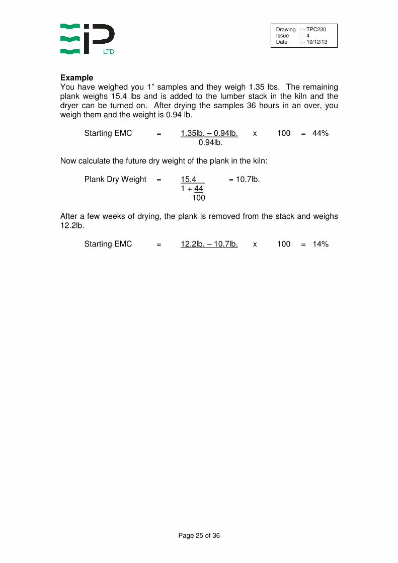
Oven Drying Method for Determining Equilibrium Moisture Content If an accurate moisture meter is not available, then moisture content can be determined using the oven dry method. The oven dry method is actually more accurate than moisture meters, but not very convenient. You do need and accurate scale for weighing the wood samples and an oven (a baking oven will do) to bake the samples. Select a plank from the wood to be dried and cut 6 inches from each end and discard these cutoffs. (They will be much drier than the rest of the piece). Cut several one-inch pieces from one end until you have about a pound in weight. Weigh these and record the wet weight. Weigh the remaining portion of the plank and add it to the middle of the lumber stack in the kiln where it can be retrieved periodically to monitor equilibrium. Place the 1” sample in a 225ºF oven for 24 to 36 hours then weigh again. This is the oven dry weight. Use the formula below to calculate the starting EMC of the sample. EMC = Wet Weight - Dry Weight x 100% Dry Weight The moisture content of the lumber in the stack can now easily be monitored by periodically pulling the sample from the stack and weighing it. First, however, calculate the future dry weight of the plank by using the EMC just calculated. Plank Dry Weight = Wet Weight 1 + EMC 100 Now having calculated the plank dry weight, use the formula above for determining EMC to monitor drying progress.
Page 25 of 36
Drawing : - TPC230 Issue : - 4 Date : - 10/12/13
Example You have weighed you 1” samples and they weigh 1.35 lbs. The remaining plank weighs 15.4 lbs and is added to the lumber stack in the kiln and the dryer can be turned on. After drying the samples 36 hours in an over, you weigh them and the weight is 0.94 lb. Starting EMC = 1.35lb. – 0.94lb. x 100 = 44% 0.94lb. Now calculate the future dry weight of the plank in the kiln: Plank Dry Weight = 15.4 = 10.7lb. 1 + 44 100 After a few weeks of drying, the plank is removed from the stack and weighs 12.2lb. Starting EMC = 12.2lb. – 10.7lb. x 100 = 14%

Page 26 of 36
Drawing : - TPC230 Issue : - 4 Date : - 10/12/13
Appendix II
Troubleshooting In case of trouble, first check that all instructions in the manual have been carefully followed. Next, go through the following chart. If the problem is still not resolved, call Ebac Industrial Products Ltd. In most cases, a simple phone call will resolve the question. System Overview Air is drawn into the dryer where the moisture is extracted from it. Moisture is extracted when the air is passed through the evaporator coil. The coil is cooled to a temperature lower than dew point temperature of the air and hence condensation forms on it. The dryer consists of 7 parts:
1. Fan motor draws the air through the unit.
2. Compressor which drives the refrigeration circuit.
3. Evaporator coil – cold section of the refrigeration circuit.
4. Condenser Coil – hot section of the refrigeration circuit.
5. Capillary tube – separates the hot and cold section of the refrigeration
circuit with regard to gas flow.
6. Auxiliary heater.
The Universal Controller controls the power to the dryer and controls the amount of water to be extracted by operating the compressor in accordance with the drying control setting, i.e. : a 25% setting will run the compressor for 15 minutes in each hour. The fan runs continuously regardless of the drying control setting. The auxiliary heater runs only when the thermostat setting is greater than the kiln temperature, once the desired temperature is achieved, the heater shuts off.
Page 27 of 36
Drawing : - TPC230 Issue : - 4 Date : - 10/12/13
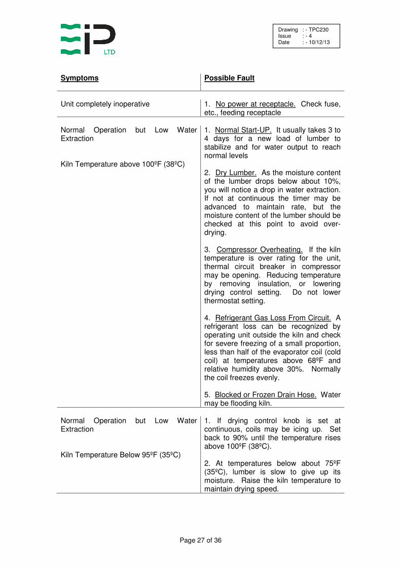
Symptoms Possible Fault Unit completely inoperative 1. No power at receptacle. Check fuse,
etc., feeding receptacle Normal Operation but Low Water Extraction
1. Normal Start-UP. It usually takes 3 to 4 days for a new load of lumber to stabilize and for water output to reach normal levels
Kiln Temperature above 100ºF (38ºC) 2. Dry Lumber. As the moisture content
of the lumber drops below about 10%, you will notice a drop in water extraction. If not at continuous the timer may be advanced to maintain rate, but the moisture content of the lumber should be checked at this point to avoid over-drying.
3. Compressor Overheating. If the kiln
temperature is over rating for the unit, thermal circuit breaker in compressor may be opening. Reducing temperature by removing insulation, or lowering drying control setting. Do not lower thermostat setting.
4. Refrigerant Gas Loss From Circuit. A
refrigerant loss can be recognized by operating unit outside the kiln and check for severe freezing of a small proportion, less than half of the evaporator coil (cold coil) at temperatures above 68ºF and relative humidity above 30%. Normally the coil freezes evenly.
5. Blocked or Frozen Drain Hose. Water
may be flooding kiln. Normal Operation but Low Water Extraction
1. If drying control knob is set at continuous, coils may be icing up. Set back to 90% until the temperature rises above 100ºF (38ºC).
Kiln Temperature Below 95ºF (35ºC) 2. At temperatures below about 75ºF
(35ºC), lumber is slow to give up its moisture. Raise the kiln temperature to maintain drying speed.

Page 28 of 36
Drawing : - TPC230 Issue : - 4 Date : - 10/12/13
Symptoms Possible Fault Low Kiln Temperature Normal Water Extraction
1. As long as water extraction is normal, kiln temperature cannot be too low. In fact, the lower the temperature the better the wood quality. The insulation thickness’ in Table 1 provides for 50ºF (28ºC) temperature rise over the outside temperature at continuous drying control setting. Lower settings will give lower temperature rise.
Mold or Mildew on Lumber 1. This condition is not harmful to the
lumber, but can be minimized with improved airflow or higher kiln temperature.
Bottom Layer or Two of Lumber Not Dry 1. This is caused by large temperature
differences (greater than 5ºF) from top to bottom of the kiln. Greater airflow or a better door seal will usually improve this.
Temperature in Kiln Continues to Rise Above Thermostat Setting
**DO NOT LOWER THERMOSTAT SETTING**
1. Thermometer on controller may need
to be adjusted. If extraction maintains at normal rate, check temperature in the kiln with thermometer at the base of the dryer. If the temperature reads lower or higher than the thermometer needle on the controller, call Ebac for adjustment procedure.
2. If temperature reads the same and
extraction ceases or slows substantially, you may have a “temporary over-insulation situation”. Simply peel back a corner of insulation from the top of you kiln chamber. If this does not remedy the situation in 24 hours, call Ebac.

Page 29 of 36
Drawing : - TPC230 Issue : - 4 Date : - 10/12/13
Appendix III
Drawings and Specifications
Page 30 of 36
Drawing : - TPC230 Issue : - 4 Date : - 10/12/13
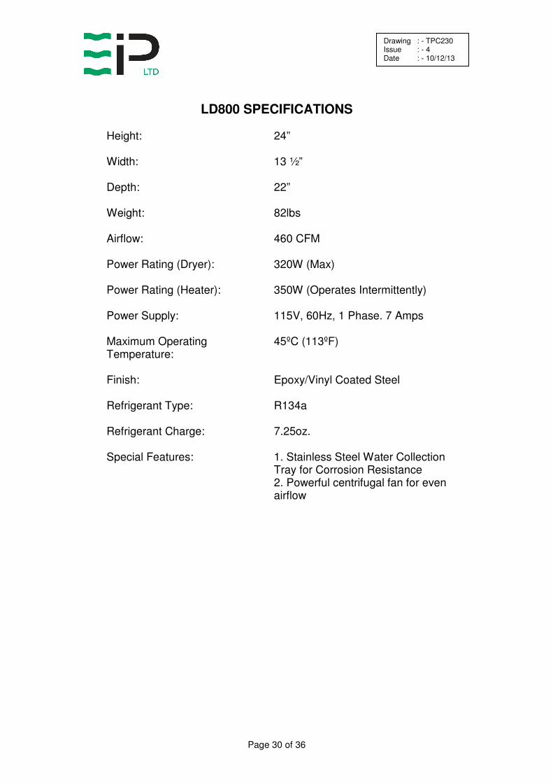
LD800 SPECIFICATIONS
Height:
24”
Width:
13 ½”
Depth:
22”
Weight:
82lbs
Airflow:
460 CFM
Power Rating (Dryer):
320W (Max)
Power Rating (Heater):
350W (Operates Intermittently)
Power Supply:
115V, 60Hz, 1 Phase. 7 Amps
Maximum Operating Temperature:
45ºC (113ºF)
Finish:
Epoxy/Vinyl Coated Steel
Refrigerant Type:
R134a
Refrigerant Charge:
7.25oz.
Special Features:
1. Stainless Steel Water Collection Tray for Corrosion Resistance 2. Powerful centrifugal fan for even airflow

Page 31 of 36
Drawing : - TPC230 Issue : - 4 Date : - 10/12/13
SPARE PARTS LIST LD800
DESCRIPTION
EBAC PART NO. QUANTITY
1. Drain Tray 2830107
1
2. Evaporator Coil 2320515
1
3. Condenser Coil 3020740
1
4. Compressor 3022194
1
5. Filter Dryer 3020937
1
6. Fan Motor 3930101
1

Page 32 of 36
Drawing : - TPC230 Issue : - 4 Date : - 10/12/13

Page 33 of 36
Drawing : - TPC230 Issue : - 4 Date : - 10/12/13

Page 34 of 36
Drawing : - TPC230 Issue : - 4 Date : - 10/12/13
German Sales Office
Ebac Industrial Products Ltd. Gartenfelder Str. 29-37
Gebäude 35 D-13599, Berlin
Germany
Tel: +49 3043 557241 Fax: +49 3043 557240
www.eip-ltd.de
American Sales Office
Ebac Industrial Products Inc 700 Thimble Shoals Blvd. Suite 109, Newport News
Virginia, 23606-2575 USA
Tel: +01 757 873 6800 Fax: +01 757 873 3632
www.ebacusa.com
UK Head Office
Ebac Industrial Products Ltd St Helens Trading Estate
Bishop Auckland County Durham
DL14 9AD
Tel: +44 (0) 1388 664400 Fax: +44 (0) 1388 662590
www.eipl.co.uk

Page 35 of 36
Drawing : - TPC230 Issue : - 4 Date : - 10/12/13

Page 36 of 36
Drawing : - TPC230 Issue : - 4 Date : - 10/12/13
LIMITED WARRANTY
Our products carry a one-year unconditional warranty against any defects in workmanship or material. This warranty will cover all parts and labor required to repair your Ebac product. This warranty is invalid if the unit has been abused, damaged, whether intentional or accidental, or if any modifications have been made to the unit. THE FOREGOING WARRANTY IS EXCLUSIVE AND IS ISSUED IN LIEU OF ALL OTHER WARRANTIES (WHETHER WRITTEN, ORAL, OR IMPLIED) INCLUDING THE WARRANTY OF MERCHANTABILITY AND THE WARRANTY OF FITNESS FOR A PARTICULAR PURPOSE. EBAC INDUSTRIAL PRODUCTS, INC. DISCLAIMS ANY LIABILITY FOR CONSEQUENTIAL DAMAGES, LOST PROFITS, OR INCIDENTAL DAMAGES FOR BREACH OF ANY WRITTEN OR IMPLIED WARRANTY WITH RESPECT TO THE FOREGOING DESCRIBED MERCHANDISE. For Your Records: Model:____________________ S/N:______________________ Date Received:______________
SAVE THIS SECTION FOR YOUR RECORDS
CLIP AND RETURN THIS CARD
PLEASE NOTE WARRANTY REGISTRATION
To ensure that your Ebac Dehumidifier is accorded the full coverage provided by this warranty, please complete and mail this card at your earliest convenience.
Thank You
DATE MODEL ___________ S/N ________________ RECEIVED ________________ OWNER __________________________________________________________ ADDRESS ________________________________________________________ CITY __________________________ STATE ________ ZIP _______________ COMMENTS ______________________________________________________ _________________________________________________________________
Ebac Industrial Products.
700 Thimble Shoals Boulevard, Suite 109, Newport News, Virginia. 23606-2575