lte aerial profile v1 - gutma
TRANSCRIPT

LTE Aerial Profile v1.00
November 2020

Change History
Date Version Author/Comments
2020-11-03 1.00 ACJA, GSMA and GUTMA approved version
Table of Contents 1. Introduction ................................................................................................................. 4
1.1. Overview ................................................................................................................... 4
1.2. Relationship to existing standards............................................................................. 5
1.2.1. 3GPP specifications ..................................................................................................... 5
1.3. Scope ........................................................................................................................ 5
1.4. Definitions of Acronyms and Terms .......................................................................... 6
1.4.1. List of Acronyms .......................................................................................................... 6
1.4.2. Terminology ................................................................................................................. 8
1.5. References ................................................................................................................ 9
2. LTE Aerial Data Types .............................................................................................. 10
2.1. Data Type Categories ............................................................................................. 10
2.1.1. Non-Critical Communication ...................................................................................... 10
2.1.2. Critical Communication .............................................................................................. 11
2.1.3. Video and Image Streaming (and other services) ...................................................... 12
2.2. Data Traffic Prioritization ......................................................................................... 12
2.3. Key Performance Indicators .................................................................................... 13
3. UAVs Density and Demand ...................................................................................... 14
4. Radio and Packet Core Feature Set ........................................................................ 14
4.1. Quality of Service Class Identifier ........................................................................... 14
4.2. Bearer Management ............................................................................................... 17
4.2.1. Access Point Name (APN) Considerations for UAS Critical and non-Critical Communications ....................................................................................................................... 17
4.2.1.1. EPS Bearer Considerations for UAS Critical Communications ................................... 17
4.2.1.2. EPS Bearer Considerations for UAS Non -Critical Communications .......................... 17

4.2.2. APN and EPS Bearer Considerations for Video and Image Streaming ...................... 18
4.3. LTE Release 15 Aerial Features ............................................................................. 18
4.3.1. Power control ............................................................................................................. 19
4.3.2. Height Reporting ........................................................................................................ 20
4.3.3. Interference Measurements ....................................................................................... 21
4.3.4. Subscription based Aerial identification and Authorization ......................................... 22
4.3.5. Route / waypoint reporting ......................................................................................... 23
5. Common Functionalities .......................................................................................... 23
5.1. IP Version ............................................................................................................... 23
5.2. Roaming Consideration ........................................................................................... 24
Appendix A. Input to Further work in 3GPP ................................................................... 25
Appendix B. Different Case Scenarios and UAV densities ........................................... 26

4
1. Introduction 1.1. Overview
The LTE Aerial Profile identifies a minimum mandatory set of features which are defined in 3GPP
specifications which an aerial wireless device (the User Equipment (UE)) and network are required
to implement in order to guarantee an interoperable, LTE aerial service over Long Term Evolution
(LTE) radio access. As further described in the section 1.3, Scope, the primary use case considered
is UAS, but does not exclude similar uses of 3GPP systems as a method of communication to
support commercial applications in low altitude airspace. The scope includes the following aspects:
Data types and requirements [Chapter 2].
Description of aerial scenarios in the scope of this document [Chapter 3].
LTE radio and evolved packet core capabilities [Chapter 4].
Functionality that is relevant across the protocol stack and subsystems [Chapter 5].
3GPP current and future standardization [Annex A].
The UE and network protocol stacks forming the scope of the LTE Aerial Profile are depicted in
Figure 1 below:
Figure 1: Depiction of UE and Network Protocol Stacks in LTE Aerial Profile
For the purposes of development of the User Network Interface (UNI) Aerial profile and the implementations demonstrated to date, we will assume that all data sent is IP data and that TCP is primarily used protocol for Critical & non-Critical Communication, and UDP is the primary protocol for Video & Image Streaming. This assumption does not preclude the use of UDP for Critical & Non-Critical Communication.
The scope of the User to Network Interface as profiled is between the Aerial UE and the RAN/CN
as shown in Figure 1."
The main body of this paper is applicable for a scenario where LTE Aerial service is deployed over
LTE in a standalone fashion without relying on any legacy infrastructure, packet or circuit switched.
In order to be compliant with LTE Aerial Profile, the UEs and networks must be compliant with all
of the normative statements in the main body.

5
1.2. Relationship to existing standards
1.2.1. 3GPP specifications
This profile is solely based on the open and published 3GPP specifications in its Release 15. 3GPP
Release 15, the release supporting LTE Aerial enhancements, is taken as a basis. It should be
noted, however that not all the features mandatory in 3GPP Release 15 are required for compliance
with this profile.
Conversely, some features required for compliance with this profile are based on functionality
defined in 3GPP Release 16 or higher releases.
All such exceptions are explicitly mentioned in the following sections along with the relevant Release
15 or higher 3GPP release specifications, respectively.
Unless otherwise stated, the latest version of the referenced specifications for the relevant 3GPP
release applies.
1.2.2. UTM specifications
UTM standards exist or are in definition that have applicability to UTM related functions discussed
in this profile. While the profile is based on published 3GPP Release 15 specifications, UTM features
such as those defined for Remote ID in ASTM's F3411-19 "Standard Specification for Remote ID
and Tracking" or EUROCAE's Draft ED-282 "Minimum Operational Performance Standard for UAS
E-Identification" will likely make use of the key performance indicator parameters for UAV
applications defined in this document.
1.3. Scope
This document defines a profile for LTE Aerial Service by listing a number of LTE, Evolved Packet
Core, and UE features that are considered essential to launch interoperable services. The defined
profile is compliant with 3GPP specifications. The scope of this profile is the interface between UE
and network, where the UE is considered to be an aerial device, or aerial UE, operating in low altitude
airspace (typical operation heights up to 150 meters above ground level). Though the primary aerial
UE considered in this document is a UAV (as part of a UAS), the applications of the LTE Aerial UNI
profile does not exclude consideration of the 3GPP system to support other airborne UE types, such
as crewed aviation applications and Urban Air Mobility (UAM/Air Taxi’s), etc. for which the use of the
network is similar.
The profile does not limit anybody, by any means, to deploy other standardized features or optional
features, in addition to the defined profile.

6
1.4. Definitions of Acronyms and Terms
1.4.1. List of Acronyms
Acronym
Explanation
3GPP 3rd Generation Partnership Project
AC Advisory Circular
AGL Above Ground Level
API Application Program Interface
APN Access Point Name
ASTM American Society for Testing and Materials
BVLOS Beyond Visual Line of Sight
DL Downlink
DRB Data Radio Bearer
eNB eNodeB
EPC Evolved Packet Core
EPS Evolved Packet System
EUROCAE European Organisation for Civil Aviation Equipment
FAA Federal Aviation Administration
FCC Federal Communications Comission
GCS Ground Control Station
GPS Global Positioning System
IP Internet Protocol
IPv4 Internet Protocol Version 4
IPv6 Internet Protocol Version 6

7
Acronym
Explanation
KPI Key Performance Indicators
LOS Line of Sight
LTE Long Term Evolution
MSS Maximum Segment Size
PC Power Control
PCRF Policy and Charging Rules Function
PDB Packet Delay Budget
PDN Packet Data Network
PELR Packet Error Loss Rate
P-GW PDN Gateway
QCI Quality of Service Class Indicator
RAN Radio Access Network
RRC Radio Resource Control
RRM Radio Resource Management
RSRP Reference Signal Received Power
RSRQ Reference Signal Received Quality
RTT Round Trip-Time
TTT Time to Trigger
UAM Urban Air Mobility
UAS Unmanned Aircraft System
UAV Unmanned Aerial Vehicle
UDP User Datagram Protocol
8
Acronym
Explanation
UE User Equipment
UL Uplink
USS UAS Service Supplier
UTM Unmanned Traffic Management
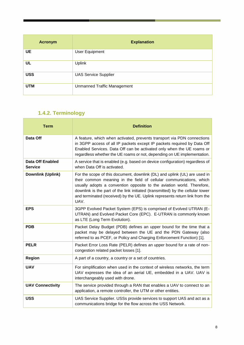
1.4.2. Terminology
Term
Definition
Data Off A feature, which when activated, prevents transport via PDN connections
in 3GPP access of all IP packets except IP packets required by Data Off
Enabled Services. Data Off can be activated only when the UE roams or
regardless whether the UE roams or not, depending on UE implementation.
Data Off Enabled
Service
A service that is enabled (e.g. based on device configuration) regardless of
when Data Off is activated.
Downlink (Uplink) For the scope of this document, downlink (DL) and uplink (UL) are used in
their common meaning in the field of cellular communications, which
usually adopts a convention opposite to the aviation world. Therefore,
downlink is the part of the link initiated (transmitted) by the cellular tower
and terminated (received) by the UE. Uplink represents return link from the
UAV.
EPS 3GPP Evolved Packet System (EPS) is comprised of Evolved UTRAN (E-
UTRAN) and Evolved Packet Core (EPC). E-UTRAN is commonly known
as LTE (Long Term Evolution).
PDB Packet Delay Budget (PDB) defines an upper bound for the time that a
packet may be delayed between the UE and the PDN Gateway (also
referred to as PCEF, or Policy and Charging Enforcement Function) [1].
PELR Packet Error Loss Rate (PELR) defines an upper bound for a rate of non-
congestion related packet losses [1].
Region A part of a country, a country or a set of countries.
UAV For simplification when used in the context of wireless networks, the term
UAV expresses the idea of an aerial UE, embedded in a UAV. UAV is
interchangeably used with drone.
UAV Connectivity The service provided through a RAN that enables a UAV to connect to an
application, a remote controller, the UTM or other entities.
USS UAS Service Supplier. USSs provide services to support UAS and act as a
communications bridge for the flow across the USS Network.

9
1.5. References
[1] 3GPP, “Policy and charging control architecture,” TS 23.203, 16.2.0, 2019.
[2] 3GPP, “General Packet Radio Service (GPRS) enhancements for Evolved Universal Terrestrial Radio
Access Network (E-UTRAN) access,” TS 23.401, Release 16.6.0, 2020.
[3] 3GPP, “Non-Access Stratum (NAS) protocol for Evolved Packet System (EPS); Stage 3,” TS 24.301,
Release 16.4.0, 2020.
[4] R. Amorim, P. Mogensen, T. Sørensen, I. K. Wigard and J. Wigard, “Pathloss Measurements and
Modeling for UAVs connected to cellular networks,” in IEEE VTC Spring 2017, 2017.
[5] R. Amorim, H. Nguyen, J. Wigard, I. Z. Kovács, T. B. Sørensen, D. Z. Biro, M. Sørensen and P.
Mogensen, “Measured Uplink Interference Caused by Aerial Vehicles in LTE Cellular Networks,” IEEE
Wireless Communications Letters, vol. 7, no. 6, pp. 958-961, 2018.
[6] 3GPP, “Evolved Universal Terrestrial Radio Access (E-UTRA); Physical layer procedures,” TS 36.213,
Release 15.9.0, 2020.
[7] 3GPP, “Evolved Universal Terrestrial Radio Access (E-UTRA); Radio Resource Control (RRC); Protocol
Specification.,” TS 36.331, Release 15.9.0, 2020.
[8] N. J. Quintero, “Advanced Power Control for UTRAN LTE Uplink,” Aalborg University, 2008.
[9] M. Coupechoux and J.-M. Kelif, “How to set fractional power control compensation in LTE?,” in 34th
IEEE Sarnoff Symposium, May 2011.
[10] Nokia, “Reliable 3D connectivity for drones over LTE networks - How cellular networks can enable
beyond visual line of sight drone flights,” 2018.
[11] R. Amorim, J. Wigard, H. Nguyen, I. Z. Kovacs and P. Mogensen, “Machine-Learning Identification of
Airborne UAV-UEs Based on LTE Radio Measurements,” in IEEE Globecom Workshops (GC Wkshps),
Singapore, 2017.
[12] J. Stanczak, D. Kozioł, I. Z. Kovács, J. Wigard, M. Wimmer and R. Amorim, “Enhanced Unmanned Aerial
Vehicle Communication Support in LTE-Advanced,” in EEE Conference on Standards for
Communications and Networking (CSCN), 2018.
[13] G. Pocovi, M. L. T. Kolding, R. Mogensen, C. Markmller and R. Jess-Williams, “Measurement
Framework for Assessing Reliable Real-Time Capabilities of Wireless Networks,,” IEEE
Communications Magazine, vol. 56, no. 12, pp. 156-163, December 2018.
[14] FCC Report on Section 374 of the FAA Reauthorization Act, Wireless Telecommunications Bureau,
Office of Engineering and Technology, August 27, 2020.
[15] IETF RFC 879; "TCP Maximum Segment Size", November 1983.

10
2. LTE Aerial Data Types
The development of LTE Aerial Data Types is done in consideration to serve the primary functions
of UAV connectivity. These categories are a result of extensive survey across the industry to
determine commercial demand for airborne UEs as of the publication of the Aerial UNI Profile. As
noted in section 1.3, Scope, the reference to UAV does not preclude the application of the LTE UNI
Profile to other, similar use cases.
2.1. Data Type Categories
2.1.1. Non-Critical Communication
Non-critical communication may include the operational state of the UAV, including configuration of UAS elements. This data may also flow to a central management system or USS to facilitate operational overview of fleet management and provide situational awareness.
Examples of non-critical communications in 4G LTE connected UAVs may include but is not limited to the following applications.
Aircraft System Telemetry
Routine measurements from aircraft subsystems. These are generally small messages sent at 1Hz at data rates approximately 30 kbps.
Battery Status
Speed
Heading
Location/GPS
Sensor Commands, Messages & Telemetry
GCS to UAV on-board sensors supporting payload functions such as cameras, for query and configuration
messages from UAV with sensor status report, heartbeat of on-board sensors, and identification of individual sensors and capabilities
commands to UAV for image capture and confirmation of image capture from UAV
Sensor command and configuration messages may follow the command protocol, requiring acknowledgement messaging and retransmitting commands multiple times before failure.
Parameters/Configuration Messages
This messaging is done periodically and as needed and consists of small data messages.
GCS requests parameter read from UAV
GCS issues write of new parameter command
11
UAV broadcasts parameter
UTM Messaging
Non-critical communications UTM messaging may include:
Airspace Access
Weather Alerts
Operational Volumes
It is important to note that data, which is not considered critical communication, may become critical based on the UAS design. For example, video streaming may become critical if it is used for detect and avoid of air traffic or other obstacles, and therefore may become classified as a UTM function.
2.1.2. Critical Communication
Critical communication may include commands issued for the purpose of facilitating control of the UAV. These data types occur at very low data rates. The rate at which these messages are emitted is system dependent.
Examples of critical communications in 4G LTE connected UAVs may include but is not limited to the following applications.
Vehicle and Mission Commands, Messaging & Telemetry
GCS to UAV commands may include flight plan changes for navigation/movement, speed changes, or conditional commands
UAV to GCS messaging may include mission requests, acknowledgement of mission completion, messaging when a new waypoint is reached, and other mission status messages
UAV may also download a mission in response to these messages, and provide an acknowledgement message containing the final result of the operation
Autopilot messages may be configured for guaranteed delivery, requiring corresponding acknowledgement. In the absence of this acknowledgement, the commands may automatically be re-transmitted until acknowledgement is received. This mechanism is used to ensure transmission over a lossy link.
Heartbeat
A heartbeat is a broadcasted message from the UAV which is used to confirm the aircraft has connectivity. An example of use may be an LTE connected BVLOS mission requiring a heartbeat confirmation to ensure the UAV has cellular connectivity before entering the BVLOS stage of flight.
UTM Messaging
Critical communications UTM messaging may include:
Remote ID
Geofencing

12
Flight Authorization
It is important to note that data which is not considered critical communication may become critical based on the UAS design.
2.1.3. Video and Image Streaming (and other services)
The video and image streaming datatype (which can also be extended to other application payloads) are considered a best effort service. The parameter optimization for this data type is left as implementation decision.
Use of low bandwidth payload transfer on UAVs may include but is not limited to the following applications.
Video Streaming
Video streaming is primary for the purpose of payload support. Payload is the business function of the UAV. This can be used for linear inspection, where the video is being streamed over the network for analytics and real time processing. Video streaming may also be used for real time operations. In this scenario, an operator may be in a remote location and reviewing the video stream to make an operational decision which may or may not impact the UAV. An operational decision which impacts the UAV may be a “return to home” command (via waypoint update message) or a new mission push (consisting of a UTM message for airspace access request, and a new flight path via waypoint update message). An operational decision which may not impact the UAV may be the action to dispatch a crew to a location. Note: The use of Video streaming for real time operations is outside the scope of the LTE Aerial Profile. It is assumed that one UAV may be associated to multiple video streams.
Image Transfer
Image transfer may also be used to support the business function of the UAV via reconnaissance. Multiple images may be captured by the UAV and used for the purpose of mapping, event detection, or real time assessment of an asset or geography. Images may be used to make operational decisions to influence the mission of a UAV by providing visual “Go” or “No Go” decisions on landing, for example. In this scenario, a UAV may be hovering and sending back pictures of a potential landing spot. An operator may receive these images and send a command for landing (via waypoint update message) to the UAV to “land” or “continue to hover” or “return home” or other.
2.2. Data Traffic Prioritization
Today, no regulation exists which places determination on priority of data for a UAS using a 3GPP system as the primary or singular data link. The purpose of exploring prioritization is to understand the role this feature plays in meeting the needs of 3GPP systems as part of a UAS.
13
Regulatory perspectives
According to ICAO1 airworthiness of UAV is based on the ICAO Airworthiness of Aircraft (Annex 8) for general aviation, which does not provide prescriptive rules on how the manufacturer can achieve airworthiness. UAS requires to have airworthiness certificates and type design certificate that are provided by the State authority of where the UAV is manufactured. As an example, in the United States, the FAA is prohibited from stating how a design objective may be met, rather offers guidance via Advisory Circulars (AC) on how an operator or manufacturer can accomplish airworthiness. This FAA guidance about system design and analysis criteria in traditional aviation (AC 25.1309) may be used to draw parallels to how the FAA may evaluate a systems capability. This AC establishes that the more severe a system failure is, the less probable it should be. In considering how an operator or an OEM may use the communications link of a UAS, some communications may have a higher level of importance to the operation of the system and thus, should be treated with higher priority. The use of this categorization, defined here as critical communications, is dependent on system design. Consider the traditional aviation example of an aircraft autopilot signalling to the flight crew via a special protocol to make sure the message is delivered. Some parallels which may be drawn to a UAS may be:
<Command Message> Land Now
<Command Message> Bank right to avoid collision
The operator/OEM must address the system response to a failure of these messages being delivered and determine the criticality of this event.
Spectrum Authorities (e.g. FCC in US, OFCOM in UK) considerations on data prioritization for critical communications are still being explored in most Countries.
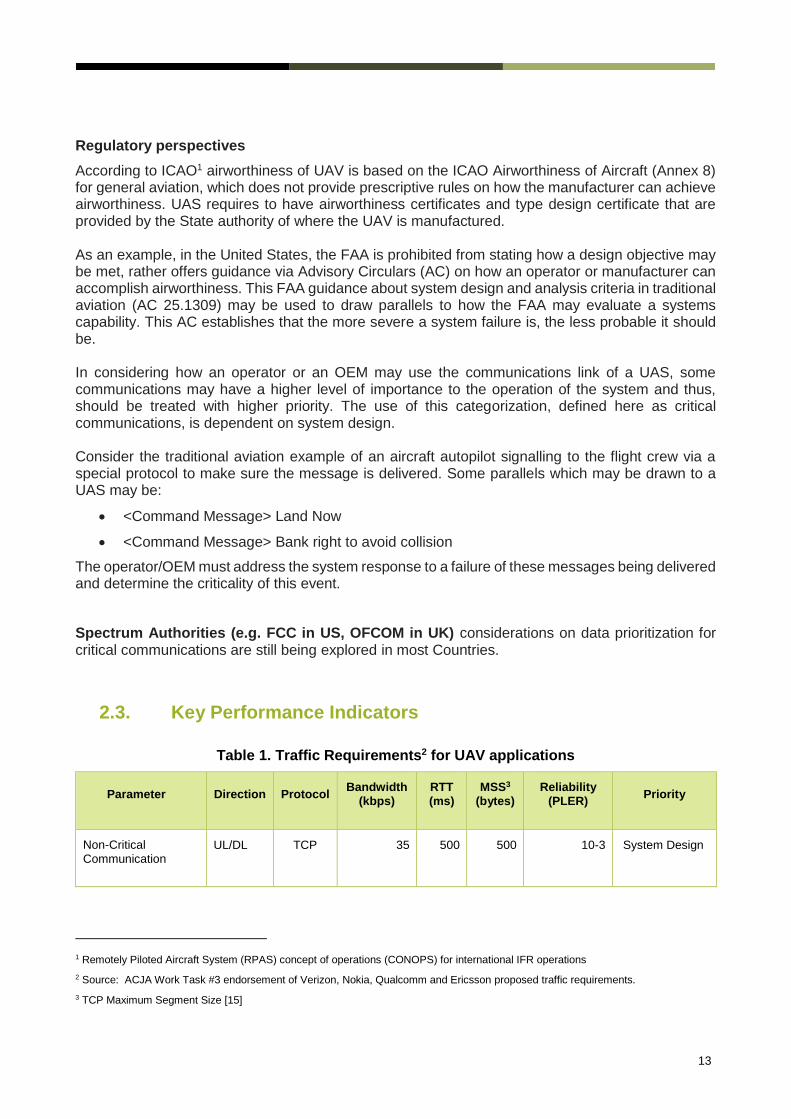
2.3. Key Performance Indicators
Table 1. Traffic Requirements2 for UAV applications
Parameter Direction Protocol Bandwidth
(kbps)
RTT
(ms)
MSS3
(bytes)
Reliability
(PLER) Priority
Non-Critical
Communication UL/DL TCP 35 500 500 10-3 System Design
1 Remotely Piloted Aircraft System (RPAS) concept of operations (CONOPS) for international IFR operations
2 Source: ACJA Work Task #3 endorsement of Verizon, Nokia, Qualcomm and Ericsson proposed traffic requirements.
3 TCP Maximum Segment Size [15]

14
Critical Communication
UL/DL TCP 35 500 100 10-5 (1) Very High
Video and Image Streaming
UL UDP 4096 500 N/A 10-3 System Design
(1) Reliability of 10-5 for Critical Communication is in reference to ARP4761, Guidelines and Methods for Conducting the Safety
Assessment Process on Civil Airborne Systems and Equipment is an Aerospace Recommended Practice from SAE International.
ARP4761 provides a framework to assess safety critical data for aircraft. This framework, which is written into FAA regulations, prescribes
higher reliability requirements for safety critical functions and data.
The standardized characteristics associated with standardized QCI values are specified in clause
6.1.7.2 in TS 23.203 [1].
3. UAVs Density and Demand
Section 2 makes clear that the critical and non-critical communication services, which are essential to maintain a safe and harmonious deployment of UAV activities require low data rates in terms of LTE typical deployments. From the network point of view, such demand can usually be met by using few network resources using regular LTE modulation and coding schemes. Moreover, due to battery concerns, UAVs will probably not fly indefinitely, and they are expected to spend a considerable amount of the ground for recharging or changing the batteries. Therefore, in scenarios where there is a low density of UAVs, it is likely that the resource allocation for UAVs will tend to be low and no big impact on the network traffic and interference patterns are expected.
However, as the number of UAVs goes up, the overall contribution of their payloads, especially with the use of more advanced applications (i.e. video streaming) are likely to negatively affect the interference level on both uplink and downlink. Definitions of different case scenarios and their respective projected densities can be found in Appendix Appendix B.
4. Radio and Packet Core Feature Set 4.1. Quality of Service Class Identifier
Technical Specifications: TS 23.203
The QoS concept as used in LTE networks is class-based, where each bearer type is assigned one QoS Class Identifier (QCI) by the network. The QCI is a scalar that is used within the access network (namely the eNodeB) as a reference to node specific parameters that control packet forwarding treatment, for example scheduling weight, admission thresholds and link-layer protocol configuration.
The QCI is also mapped to transport network layer parameters in the relevant Evolved Packet Core (EPC) core network nodes (for example, the PDN Gateway (P-GW), Mobility Management

15
Entity (MME) and Policy and Charging Rules Function (PCRF)), by preconfigured QCI to Differentiated Services Code Point (DSCP) mapping.
Initially, 3GPP had described 9 different QCI settings (identified by indexes 1-9) in its technical specification for QCIs in Release 8 [1]. The table provided in the standards maps a QCI index into different packet forwarding treatment that the bearer traffic receives edge-to-edge between the UE and the P-GW. Scheduling priority, resource type, packet delay budget and packet error loss rate are the set of characteristics defined by the 3GPP standard and they should be understood as guidelines for the pre-configuration of node specific parameters to ensure that applications/services mapped to a given QCI receive the same level of QoS in multi-vendor environments as well as in roaming scenarios.
New QCI mappings were added to the standard in the following releases, to cope with the innovative services and evolving demand from industry. After Release 15, there are about 20 different QCIs described in the standards [1].
The QCIs chosen to support a UAV application, must then have performance parameters in accordance to those described in Section 2.2 of this document. Observe that the traffic requirements for UAV applications defined in Section 2.2 presents a round-trip delay budget, whereas the QCI tables provide the performance in terms of one-way delay between UE and Core Network. Accounting for a round-trip (two-way) flow of the data, and to additional delays external to the RAN (internet relays, application layer processing, etc.), the QCI delay budget parameter may not reach or exceed 50% of the values described previously in Section 2.2.
Figure shows that there are 4 QCIs that fulfil the UAV traffic requirements (5, 69, 70 and 71).
However, their Packet Error Rate is more conservative than the requirements for Non-Critical
Communication & Video and Imaging by a wide margin (10−6 𝑣𝑠 10−3), which will represent a conservative approach by the RAN, possibly resulting in inefficient use of resources.
This document has identified different default QCIs whose operating settings fulfil the criteria established for UAV applications. As all of them are, in principle, able to cope with the requirements, no recommendation for a specific QCI is given. The choice of any of the fulfilling QCIs can be left at implementation’s discretion.
It is worth noting that, in most cases, the QCIs that fulfil the requirements present a much lower delay budget than the expected by UAV applications. Choosing one of such QCIs may result in a highly conservative approach that may trigger excessive robustness for the RAN, leading to unnecessary consumption of physical resources.

16
Figure 2. Delay budget and Packet Error Rate parameters for the QCIs described in [1].
Figure
The dashed lines are the reference values for the UAV applications. The numbers represent the index used to identify the QCI in the standard’s Table.
As an example, the following mapping of QCI values for the UAV requirements is presented in the following Table.
Table 2. List of standard QCIs fulfilling the traffic requirements
QCI Priority PDB PELR Notes
5 1 100 ms 10^-6
69 0.5 60 ms 10^-6 Delay budget too much lower than the requirements
70 5.5 200 ms 10^-6
71 5.6 150 ms 10^-6
The standardized characteristics associated with standardized QCI values are specified in clause
6.1.7.2 in TS 23.203 [1].
The mapping of these to radio parameters is described in the next sections.

17
4.2. Bearer Management
4.2.1. Access Point Name (APN) Considerations for UAS Critical and
non-Critical Communications
For UAS Critical and non-Critical Communications, the UAS application in the UE must use the UAS
well-known APN (Note: to be defined in PRD IR.88 [2]). The use of a dedicated, well-known APN
ensures that the UE implementations provide separate path for UAS Critical and non-Critical
Communications data traffic; thus, changes to other APNs for other services will not affect the path
and availability of UAS Communications services.
Note 1: The network has to be prepared to receive any APN, including the UAS well-known
APN, during the E-UTRAN initial attach procedure, as per 3GPP TS 23.401 [2] and
3GPP TS 24.301 [3]
Note 2: When preconfiguring the UE to provide the UAS well-known APN during initial
attach, the home operator needs to ensure that the UAS well-known APN is part of
the subscription of the user of the UE in order to avoid attach failure.
If the PDN connection established during the initial attach is to an APN other than the UAS well
known APN, then prior to registering with USS/UTM the UE must establish another PDN connection
to the UAS well-known APN.
4.2.1.1. EPS Bearer Considerations for UAS Critical
Communications
A default bearer must be created when the UE creates the PDN connection to the UAS well-known
APN, as defined in 3GPP specifications. As previously stated, no hard recommendation is made
regarding the QCI choice for UAS critical communications. There are 4 standard QCIs in current
3GPP spefication designed to reach the requested data constraints, (5, 69, 70, and 71). The choice
of the QCI within this subset of suitable candidates is left as a deployment decision.
4.2.1.2. EPS Bearer Considerations for UAS Non -Critical
Communications
For a UAS session request for a Non-Critical Communications, a dedicated bearer for UAS Non-
Critical Communications must be created utilizing interaction with dynamic PCC. The network must
initiate the creation of a dedicated bearer to transport the UAS Non-Mission Critical Communication
data. The dedicated bearer must utilize the standardised non-GBR QCI value and have the
associated characteristics as specified in 3GPP TS 23.203 [1].
18
4.2.2. APN and EPS Bearer Considerations for Video and Image
Streaming
For Non-Critical Video and Image streaming, and by extension for other application payloads, the UE creates a PDN connection to a different APN (for example, Internet APN), as defined in 3GPP specifications. The default bearer must utilize non-GBR QCI value and have the associated characteristics as specified in 3GPP TS 23.203 [1]. If Video and Image streaming are used to facilitate control of the UAV, the bearers are as defined in 4.2.1.1. The recommendations in this document do not preclude commercial considerations regarding the type of application used by the UAV and the network design.
4.3. LTE Release 15 Aerial Features
Regulatory Perspective on 3GPP Systems for Support of UAS Operations
CEPT Electronic Communication Committee (ECC): The ECC released in July 2020 the Report 3094 which analyses spectrum issues relative to usage of aerial UE communications within the current mobile network spectrum, including potential impact of such use on mobile networks and other systems and services and possible spectrum regulatory considerations. Results of the report are applicable to either UAVs or UEs in manned aircrafts as helicopters, or future passengers UAVs ("flying taxis"). The studies have been limited to LTE technology, with usage of "aerial" UEs up to 10000 m. The Report could be the basis of developing a framework to clarify spectrum regulatory conditions for the usage of aerial UE in the following bands: 700 MHz, 800 MHz, 900 MHz, 1800 MHz, 2 GHz, 2.6 GHz, 3.4-3.8 GHz. In conclusion, the report indicates that aerial UEs can operate in 7 bands, while requiring in some cases additional regulatory measures. Some of the measure could limit the power emission, altitude or require a creation of no-fly-zone in vicinity of certain services.
FCC: In the FCC’s report on Section 374 of the FAA Reauthorization act of 2018 frequencies licensed under flexible-use service rules, including spectrum used for commercial mobile operation, are briefly discussed for the support of UAS operations. The report acknowledges the capacity, coverage and performance needs to support economies of scale. This report highlights the need FCC’s concerns about the lack of data to confirm non-interference to terrestrial users, neighbouring licence holders/network operators and adjacent channels [14]. While the features described in the LTE Aerial UNI Profile to not specifically address adjacent bands, interference to terrestrial users are explicitly addressed in the context of the 3GPP Release 15 study “Enhanced LTE support for aerial vehicles” from which the feature definitions result. On the topic of interference on a network operators co-channel or adjacent-channel as a result of aerial operations by a separate network operator, The LTE Aerial Profile is intended to serve as a basis for interoperability and industry standardization through the adoption of these features to reduce interference caused by aerial UEs.
4 CEPT ECC REPORT 309: Analysis of the usage of aerial UE for communication in current MFCN harmonised bands
19
4.3.1. Power control
Technical Specifications: TS 36.331, TS36.213
In LTE systems, a power control mechanism is used to maximize the energy efficiency of the UE
transmission, whereas minimizing the overall system interference. Generally, the higher the received
power, the higher is the data rate achievable. However, this effect is limited by the maximum data
rate specified for the system and by the data rate required by the application in use. After this
practical limit is reached, increasing the transmitted power will result only in waste of energy and
more interference radiated toward the neighbour cells. Therefore, the power control acts to limit the
transmit power for UEs close to the base station and increases for those users with higher path loss
attenuation.
Aerial UEs, such as UAVs, differ from the classical LTE scenarios with terrestrial UEs. They are
more likely to experience LOS to their respective serving cells than a terrestrial UE, in particular in
urban areas [4]. Consequently, they tend to require a transmit power smaller than their terrestrial
counterparts in most cases. At the same time the interference received by non-serving cells is
significantly higher than for the same user on the ground, especially when UAVs are using a
significant amount of network resources [5].This will cause the uplink throughputs of other uplink
users in those cells, including the terrestrial users, to be affected negatively. This is one of the main
reasons to control the uplink power of UAVs.
One straightforward way to differentiate the network treatment toward UAVs and terrestrial UEs,
according to their specificities, is to use UE-specific parameters to adjust the PC settings. There are
two parameters that can be adjusted: P0 and alpha [6]. P0 can be regarded as a target received
power level at the eNodeB, whereas alpha is the fraction of the estimated path loss to be
compensated by the user.
The parameter alpha can assume values restricted to the set {0, 0.4, 0.5, 0.6, 0.7, 0.8, 0.9, 1} [7]. If
alpha is set equal to 1.0, then all users will fully compensate for the path loss, and the average
received power will be fully governed by P0. Previous studies have demonstrated that, this tends to
limit the throughput for the user with better path loss conditions [8], and also the overall cell
throughput [9]. If alpha is below 1.0, then the users with better path loss conditions are favoured, if
they have the same P0. In a coexistence scenario, this tends to favour UAVs in detriment of the
terrestrial UEs.
In general, optimizing alpha is a complex task that depends on the scenario characteristics. In
practical cases, the value of alpha is set the same for all users. But P0 can also be used to minimize
the UL interference caused by UAVs. By using a lower P0 for aerial UEs compared to terrestrial
users they will use a lower output power, and therefore cause less interference. As shown in [10] by
controlling P0 the interference can be controlled.
In order to accommodate for the different scenarios, in 3GPP’s release 15, the UE specific P0 offset
parameter (UplinkPowerControlDedicated-v1530) is set to a wider range (from -16 dB to 15 dB) in
comparison to legacy versions(-8 dB and 7 dB) [7], whereas the UE specific alpha factor choices
remains unchanged.

20
Reasons for using P0 compared to alpha is that it controls the received power at the serving cell and
as the serving cell and interfered cells level related to each other, it also controls the interference
indirectly.
The network has however other methods than the ones described above. One example of those is
the use of closed loop power control commands to decrease the output power of certain UEs, which
can be utilized to decrease the output power of UAVs to protect other UEs.
This may be an attractive solution when the density of UAVs in the network is very low when
compared to the massive number of terrestrial UEs. Additionally, for non-critical and critical
communications the UAV require very low bandwidth, which therefore tends to require few UL
resources, minimizing the UL impact in interference in these cases.
Table 3. RAN and UE requirements related to power control
Low Density Scenarios High Density Scenarios
Feature Mandatory/
optional at the UE
Mandatory/ optional at
RAN
Mandatory/ optional at the
UE
Mandatory/ optional at
RAN
UAV specific
alpha
Optional Optional Mandatory Optional
UAV specific
P0
Optional Optional Mandatory Optional
RAN
mechanism to
decrease
power of UAVs
(e.g. Closed
Loop Power
Control)
N.A. Optional N.A. Mandatory
4.3.2. Height Reporting
Technical Specification: TS 36.331
As the UE moves within the network area, it may happen that a connected UE gradually transitions
from the coverage area of one cell into the coverage area of another. The decision to handover the
UE context and link to a different eNodeB is network centric. In order to support this procedure, the
LTE Radio Resource Control (RRC) protocol requires the UE to periodically measure the radio signal
conditions from serving and neighbouring cells. Measurement reports are sent to the eNodeB upon
some radio criteria specified by the RRC protocol (measurement events).
For legacy UEs these events are all conditioned to radio conditions: serving and neighbouring
received signal strength compared against predefined thresholds. For aerial UEs two new events
are introduced, H1 and H2:
Event H1: UE height becomes higher than a threshold

21
Event H2: UE height becomes lower than a threshold
In addition to the common measurement reports, the height-dependent measurement report may
contain the UE 3D location and speed (both vertical and horizontal). The reception of such reports
by the network may be used to adjust the UE’s mobility related parameters, such as the thresholds
and Time-to-Trigger (TTT) or the power control settings (see previous section). The benefit is that
previous studies have indicated that the mobility performance of Aerial UE’s can be affected by its
height and speed. By choosing more appropriate settings, the network may improve the mobility
performance of these users.
As the main aim of this new measurement is to differentiate between a UE on the ground and a UE
in the air, such that for instance different treatment can be ensured of a UAV which is on the ground
or flying in the air, the network may use other means to detect whether a UE is in the air or not.
Methods exist like described in [11].
Table 4. RAN and UE requirements related to height reporting
Low Density Scenarios High Density Scenarios
Feature Mandatory/
optional at the UE
Mandatory/ optional at RAN
Mandatory/ optional at the UE
Mandatory/ optional at RAN
Support for
reporting events
H1 and H2
Mandatory Optional Mandatory Mandatory
4.3.3. Interference Measurements
Besides assisting mobility decisions, some of the measurement events defined for LTE Radio
Resource Management (RRM) can also provide useful information about the potential DL
interference observed by an UE. These events, which may be set to measure either Reference
Signal Received Power (RSRP) or Reference Signal Received Quality (RSRQ), are:
Event A3: A measured neighbour cell becomes better than the serving cell by an offset
Event A4: A measured neighbour cell becomes better than a threshold
Event A5: The serving cell becomes worse than a threshold and a neighbour cell becomes
better than a second threshold.
As previously discussed in Subsection 4.3.1, an airborne UAV, flying above the clutter, is likely to
experience LOS with multiple base stations, and to be reachable for a wider range. Consequently, it
will likely observe a more number of interfering cells. This may cause the amount of measurement
reports to increase significantly, causing an excessive load over the physical resources.
In order to circumvent this problem, the 3GPP has released new configuration possibilities for the
events A3, A4, A5 by adding a new parameter numberOfTriggeringCells. When this parameter is

22
set, a report is only sent if the number of neighbouring cells triggering the event condition is at least
equal to the value indicated in numberOfTriggeringCells.
After the new conditions are met and a measurement report is sent, no additional reports are sent
if the number of cells triggering the condition further increases, minimizing the number of times a
report is sent.
On the other hand, new interfering cells “discovered” by the UE do not trigger a report, thus this may
result in the network not identifying potentially harmful interfering neighbours. This problem can be
alleviated by the optional configuration of the “report on leave”, which triggers the transmission of a
measurement report once one of the cells leave the event condition. This is a fundamental change
on the way previous 3GPP reporting worked, i.e. by reporting any new potentially harmful neighbour
cells. However, simulations presented in [12] have demonstrated that the “report on leave” can be
used to perform frequent updates on the “interfering cell set” reported by the UE.
Despite these modifications, in certain scenarios, the LOS likelihood experienced by airborne UAVs
may still trigger a high number of measurement reports, as presented in [12]. And this may be an
object of further enhancements in future 3GPP releases. Another option, alternative to the “report
on leave”, is to set the measurement event using the numberOfTriggeringCells parameter and upon
the measurement triggering, update the UE measurement configuration to send periodic reports.
Several alternative methods exist to achieve the same result, through a combination of existing UE
measurements.
Table 5. RAN and UE requirements related to interference measurements
Low Density Scenarios High Density Scenarios
Feature Mandatory/
optional at the UE
Mandatory/ optional at RAN
Mandatory/ optional at the UE
Mandatory/ optional at RAN
Support for parameter
numberOfTriggeringCells
Optional Optional Optional Optional
Support for “report on
leave”
Optional Optional Optional Optional
High interference
detection from UAV by
RAN
N.A Optional N.A Mandatory
4.3.4. Subscription based Aerial identification and Authorization
3GPP has also recognized the need for aerial identification. Identifying whether the UE is permitted
to fly (i.e., usage as a UAV is permitted). This would likely be related to UE’s indication of radio
capability to the network in combination with the subscription information. Aerial UE identification
can be based on a combination of user based identification via subscription information through the
SIM (Subscriber Identity Model) credentials and device functionality based identification via LTE
radio capability signalling. The Mobility Management Entity (MME) can signal the subscription
information to the eNodeB which can include information on whether the user is authorized to

23
operate for aerial usage. In addition, an aerial UE as LTE device can indicate its support of aerial
related functions via regular radio capability signalling to the eNodeB.
Table 6. RAN and UE requirements related to subscription based aerial identification and
authorization
Feature Mandatory/
optional at the UE
Mandatory/ optional
at the network
Subscription based aerial
identification and authorization
N/A Mandatory
4.3.5. Route / waypoint reporting
Release 15 has introduced the possibility for the network to ask for the location and the planned
flight route of the UAVs. The network can send a UEInformationRequest message including
parameter flightPathInformationReq and the UE should reply with a flight path information included
in UEInformationResponse message consisting of up to 20 waypoints. Each waypoint is composed
of a 3D location information, optionally combined with a time stamp to provide the expected time of
arrival of the UE at that location with a maximum of one second granularity.
This information can be used to provide early resource reservation in cells suitable for a handover
and by doing so, ensure a higher QoS, for instance. Also the reliability of the handover can be
improved and thereby minimize the number of handover failures. Information about the flight route
is also useful for future features like conditional handover, which is being considered for NR.
Release 15 is however not perfect as large parts of the content are left to the UE implementation.
The standard does not specify the distance between the waypoints reported by the UE or the
accuracy of the provided information.
Table 7. RAN and UE reporting related to waypoint reporting
Feature Mandatory/
optional at the UE
Mandatory/ optional
at the network
Route/waypoint reporting Optional Optional
5. Common Functionalities 5.1. IP Version
The UE and the network must support both IPv4 and IPv6 for all protocols that are used for the Aerial
application. At PS attach, the UE must request the PDN type: IPv4v6, as specified in section 5.3.1.1
in 3GPP TS 23.401 [10]. If both IPv4 and IPv6 addresses are assigned for the UE, the use of the
IPv6 address type must be preferred.

24
Note: There are certain situations where interworking between IP versions is required.
These include, for instance, roaming and interconnect between networks using
different IP versions. In those cases, the network needs to provide the interworking
in a transparent manner to the UE.
5.2. Roaming Consideration
Further work is needed in the GSMA Network Group on the roaming model(s) that would be needed
to support LTE Aerial Roaming.

25
Appendix A. Input to Further work in 3GPP
As identified in the previous sections, LTE provides rather good support for UAV connectivity.
However, the aerial features defined for LTE are not yet defined for NR, whereas they would also be
required. Therefore, for NR the following features should be considered:
UAV specific power control, in similar manner as described in section 4.3.1.
UAV height reporting, in similar manner as described in section 4.3.2, but including
specifying requirements related to the accuracy.
UAV measurement optimizations to minimize the measurement reporting
Aerial identification and authorization through subscription or other potentially other
means.
UAV route reporting, which can be used to improve mobility robustness and reliability.
Furthermore the following can be considered:
Modifications to beamforming from both UE and network side to enable interference
management while providing high UL throughput from the UAV.
26
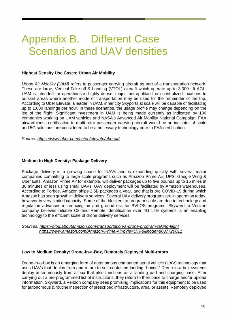
Appendix B. Different Case Scenarios and UAV densities
Highest Density Use Cases: Urban Air Mobility
Urban Air Mobility (UAM) refers to passenger carrying aircraft as part of a transportation network. These are large, Vertical Take-off & Landing (VTOL) aircraft which operate up to 3,000+ ft AGL. UAM is intended for operations in highly dense, major metropolitan from centralized locations to outskirt areas where another mode of transportation may be used for the remainder of the trip. According to Uber Elevate, a leader in UAM, inner city Skyports at scale will be capable of facilitating up to 1,000 landings per hour. In these scenarios, the usage profile may change depending on the leg of the flight. Significant investment in UAM is being made currently as indicated by 100 companies working on UAM vehicles and NASA's Advanced Air Mobility National Campaign. FAA airworthiness certification to multi-rotor passenger carrying aircraft would be an indicator of scale and 5G solutions are considered to be a necessary technology prior to FAA certification.
Source: https://www.uber.com/us/en/elevate/uberair/
Medium to High Density: Package Delivery
Package delivery is a growing space for UAVs and is expanding quickly with several major companies committing to large scale programs such as Amazon Prime Air, UPS, Google Wing & Uber Eats. Amazon Prime Air for example, will deliver packages up to five pounds up to 15 miles in 30 minutes or less using small UAVs. UAV deployment will be facilitated by Amazon warehouses. According to Forbes, Amazon ships 2.5B packages a year, and that is pre COVID-19 during which Amazon has seen growth in delivery services. Several UAV delivery programs are in operation today, however in very limited capacity. Some of the blockers to program scale are due to technology and regulation advances in reducing air and ground risk for BVLOS programs. Skyward, a Verizon company believes reliable C2 and Remote Identification over 4G LTE systems is an enabling technology to the efficient scale of drone delivery services.
Sources: https://blog.aboutamazon.com/transportation/a-drone-program-taking-flight https://www.amazon.com/Amazon-Prime-Air/b?ie=UTF8&node=8037720011
Low to Medium Density: Drone-in-a-Box, Remotely Deployed Multi-rotors
Drone-in-a-box is an emerging form of autonomous unmanned aerial vehicle (UAV) technology that uses UAVs that deploy from and return to self-contained landing “boxes.” Drone-in-a-box systems deploy autonomously from a box that also functions as a landing pad and charging base. After carrying out a pre-programmed list of instructions, they return to their base to charge and/or upload information. Skyward, a Verizon company sees promising implications for this equipment to be used for autonomous & routine inspection of prescribed infrastructure, area, or assets. Remotely deployed

27
multi-rotors are similar to drone-in-a-box but are not installed and are therefore less predictable in deployment areas. This use case is in strong demand for the spaces of public safety, media, emergency response, security and maintenance.
Very Low Density: Long-Range Linear Inspection
Long-range linear inspection is a most widely cited use for 4G LTE on UAVs today. These operations are typically point to point flights which take place in rural areas and can cover 40 - 100+ miles in a single operation. These operations are deployed for pipeline and transmission inspection, mapping, reconnaissance and other forms of data collection. These aircraft typically have a pre-defined area of operation, with 1-2 Units in a setting with 5-10 mile radius of operation. This is a widely deployed use of long-range UAVs today. Blockers are economic and scalable long-range communications solutions for BVLOS operations, making 4G LTE a highly desirable option to serve this market today. Regulatory advances also pose hurdles to scale and widespread adoption.
For all use cases, the primary use of the 3GPP system are:
Critical (C2) & non-critical communications over 4G LTE &/or 5G
Video, Image & Data Payload over 4G LTE &/or 5G
UTM Services over 4G LTE &/or 5G
Detect & Avoid via low latency 5G and MEC
Use Case Use Details
Highest Density:
Urban Air Mobility
Geography: Major Metropolitan Density: 1,000's of landings in 1-2 acres of airspace Airframe Type: Large frame, passenger carrying Multi-Rotor / VTOL Estimated Altitude: Ground up to 3,000 Feet AGL Flight Duration: TBD
Requirements: 5G solutions considered a requirement for scale
Market Stage: Emerging
Estimated Scale: 2024+
Unique Use Cases Details:
-May offer Infotainment (4-6 users/aircraft) -Use case dependent on stage of flight -Downlink data importance increases
-Detect & Avoid over 5G/MEC

28
Use Case Use Details
Medium to High Density:
Package Delivery
Geography: Urban, Sub-Urban & Rural Density: several UAVs in 1 mil SQ of airspace at arrival/departure from warehouse or central operations center. Airframe Type: Multi-Rotor / VTOL Estimated Altitude: Ground up to 400 Feet AGL Flight Duration: 15-45 minutes
Market Stage: Early
Estimated Scale: 2022
Indicators: Approval of sub-urban use cases for package delivery. Requirements: Reliable cellular network services.
Low to Medium Density: Drone-in-a-Box, Remotely Deployed Multi-rotors
Geography: Sub-Urban & Rural Density: Fixed area of operation, 1-2 Units in a stationary setting with 5-10 mile radius of operation Airframe Type: Multi-Rotor / VTOL (<55 lbs) Estimated Altitude: 400 Feet AGL Flight Duration: 15-45 minutes
Market Stage: Early
Estimated Scale: 2022
Indicators: Remote ID regulation and adoption. Requirements: Reliable cellular network services.
Very Low Density: Long-
Range Linear Inspection
Geography: Sub-Urban & Rural Density: Fixed area of operation, 1-2 UAV in 5-10 mile radius of operation Airframe Type: Fixed Wing / VTOL Estimated Altitude: 400+ Feet AGL Flight Duration: 1-3 hours
Market Stage: Adoption
Estimated Scale: 2022
Indicators: Repeatable BVLOS waivers granted within a certain timeframe, or rate of utility adoption. Requirements: Remote ID and reliable cellular network services.

About the GSMA
The GSMA represents the interests of mobile operators worldwide, uniting more than 750 operators and nearly 400 companies in the broader mobile ecosystem, including handset and device makers, software companies, equipment providers and internet companies, as well as organisations in adjacent industry sectors. The GSMA also produces the industry leading MWC events held annually in Barcelona, Los Angeles and Shanghai, as well as the Mobile 360 Series of regional conferences.
For more information, please visit www.gsma.com
About the GUTMA
The Global UTM Association (GUTMA) is a non-profit consortium of worldwide Unmanned Aircraft Systems Traffic Management (UTM) stakeholders. Its purpose is to foster the safe, secure and efficient integration of drones in national airspace systems. Its mission is to support and accelerate the transparent implementation of globally interoperable UTM systems. GUTMA members collaborate remotely.
For more information, please visit www.gutma.org