lse - flsekmc.co.rs/sites/default/files/2115e+f-lse+flse_3642b_en_0...lse - flse 3-phase tefv...
TRANSCRIPT
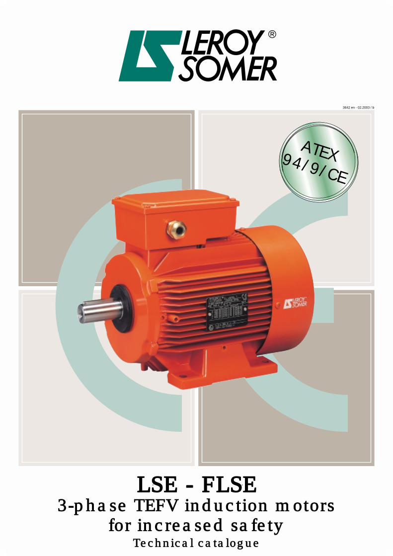
LSE - FLSE3-phase TEFV induction motors
for increased safetyTechnical catalogue
3642 en - 02.2003 / b
ATEX94/9/CE

LSE - FLSE 3-phase TEFV inductionmotors for increased safety
2
LEROY-SOMER reserves the right to modify the design, technical specifications and dimensions of the products shown in this document.The descriptions cannot in any way be considered contractual.
Copyright 2003: LEROY-SOMER
PAGE
- GENERAL INFORMATION
Quality assurance .............................................................. 4
General standardization..................................................... 5
Product approval and marking.......................................... 6
Approval ..................................................................................... 6
Marking....................................................................................... 6
Definition of atmospheres and zones .............................. 7
Atmospheres at risk of explosion................................................ 7
Definition of zones at risk of explosion ....................................... 7
Temperature classes .................................................................. 7
Definition of temperature classes according to IEC 60079-0 ..... 7
Definition of the marked temperature according toIEC 60079-7 ............................................................................... 7
Definition of "Index of Protection" (IP/IK) ........................ 8
- CONSTRUCTION
Components ....................................................................... 9
Description of LSE - FLSE 3-phase motors ............................... 9
External finish............................................................................. 9
Mains connection ............................................................. 10
Terminal box and cable gland positions.................................... 10
Cable gland for rated supply voltage of 400V........................... 10
PAGE
- ELECTRICAL CHARACTERISTICS
Selection data: LSE aluminium motors .......................... 11
Selection data: FLSE cast iron motors ........................... 21
- DIMENSIONS
Dimensions: LSE aluminium motors .............................. 31
Dimensions: FLSE cast iron motors ............................... 39
- MAINTENANCE / INSTALLATION
Identification...................................................................... 47
Documentation - Manuals ................................................ 48
Contents
LSE - FLSE 3-phase TEFV inductionmotors for increased safety
3
Index
PAGE
A
ccreditation ................................................................. 6
Ambient operating temperature..................................... 7
Approval ........................................................................ 6
ATEX ............................................................................. 6
Atmospheres ................................................................. 7
B
alancing ...................................................................... 5
Bearings ........................................................................ 9
C
able gland ................................................................. 10
Components .................................................................. 9
D
anger........................................................................... 7
Dimensions.................................................................. 31
Directions of rotation ..................................................... 9
Directive ........................................................................ 6
Documentation ............................................................ 48
Drip cover .................................................................... 38
E
arth terminal ................................................................ 9
EC type-examination certificates................................... 6
Efficiency ..................................................................... 12
EN ................................................................................. 5
End shields.................................................................... 9
Environment .................................................................. 5
External finish................................................................ 9
F
an ................................................................................ 9
Fan cover ...................................................................... 9
Finned housing.............................................................. 9
Flanges........................................................................ 38
H
eating .......................................................................... 6
I
dentification ................................................................ 47
Identification plates...................................................... 47
IEC ................................................................................ 5
Index of protection......................................................... 8
INERIS .......................................................................... 4
Instruction manual ....................................................... 48
ISO 9001 ....................................................................... 4
K
eyway.......................................................................... 9
L
ocked rotor time .......................................................... 7
PAGE
M
ains connection........................................................ 10
Marked temperature...................................................... 7
Marking ......................................................................... 6
Motor batch number.................................................... 47
Mounting positions........................................................ 5
N
otified body................................................................. 4
O
ptional features......................................................... 38
P
olarities ..................................................................... 11
Power .......................................................................... 12
Q
uality........................................................................... 4
R
ated supply voltage .................................................. 10
Risk of explosion........................................................... 7
Rotor ............................................................................. 9
S
afety............................................................................ 6
Selection data ............................................................. 11
Special manual ........................................................... 48
Speed.......................................................................... 11
Standards...................................................................... 5
Stator ............................................................................ 9
T
emperature classes .................................................... 7
Terminal box ............................................................... 10
Torque......................................................................... 12
V
IK .............................................................................. 11
Z
ones............................................................................ 7

4
LSE - FLSE 3-phase TEFV inductionmotors for increased safety
General information
A1 - Quality assurance
Industrial concerns are having to copewi th an ever more compet i t i veenvironment. Productivity depends to aconsiderable degree on the rightinvestment at the right time.LEROY-SOMER has the answer,building motors to precise standards ofquality.
When carrying out quality checks on amachine's performance, the first step isto
measure the level of customersatisfaction.
Careful study of this information tells uswhich points need looking at, improvingand monitoring.
From the moment you place your orderwith our administrative staff until themotor is up and running (after designstudies, launch and product ionactivities) we keep you informed andinvolved.
Our own processes are constantlyunder review. All our staff are involvedin both operational process analysisand continuous training programmes.These initiatives help them serve youbetter, and increased skills bringincreased motivation.
At LEROY-SOMER, we think it vital forour customers to know the importancewe attach to quality.
LEROY-SOMER has entrusted thecertification of its expertise to variousinternational organisations.Certification is granted by indepen-dent professional auditors, and re-cognises the high standards of the
company's quality assurance pro-cedures.
All activities resulting in the final ver-sion of the machine have thereforereceived official
ISO 9000
accreditation,
Edition 2000
. Products are alsoapproved by official bo-dies who inspect theirtechnical performancewith regard to the var-ious standards.This is a fundamentalrequirement for a com-pany of internationalstanding.
Our order tracking and manufactur-ing processes have been assessedfor conformity by the notified bodyINERIS.
LSE - FLSE 3-phase TEFV inductionmotors for increased safety
General information
5
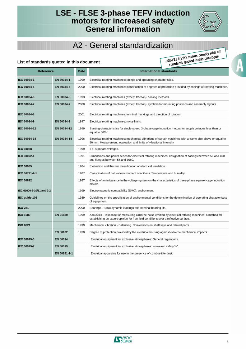
List of standards quoted in this document
Reference Date International standards
IEC 60034-1 EN 60034-1
1999 Electrical rotating machines: ratings and operating characteristics.
IEC 60034-5 EN 60034-5
2000 Electrical rotating machines: classification of degrees of protection provided by casings of rotating machines.
IEC 60034-6 EN 60034-6
1993 Electrical rotating machines (except traction): cooling methods.
IEC 60034-7 EN 60034-7
2000 Electrical rotating machines (except traction): symbols for mounting positions and assembly layouts.
IEC 60034-8
2001 Electrical rotating machines: terminal markings and direction of rotation.
IEC 60034-9 EN 60034-9
1997 Electrical rotating machines: noise limits.
IEC 60034-12 EN 60034-12
1999 Starting characteristics for single-speed 3-phase cage induction motors for supply voltages less than or equal to 660V.
IEC 60034-14 EN 60034-14
1996 Electrical rotating machines: mechanical vibrations of certain machines with a frame size above or equal to 56 mm. Measurement, evaluation and limits of vibrational intensity.
IEC 60038
1999 IEC standard voltages.
IEC 60072-1
1991 Dimensions and power series for electrical rotating machines: designation of casings between 56 and 400 and flanges between 55 and 1080.
IEC 60085
1984 Evaluation and thermal classification of electrical insulation.
IEC 60721-2-1
1987 Classification of natural environment conditions. Temperature and humidity.
IEC 60892
1987 Effects of an imbalance in the voltage system on the characteristics of three-phase squirrel-cage induction motors.
IEC 61000-2-10/11 and 2-2
1999 Electromagnetic compatibility (EMC): environment.
IEC guide 106
1989 Guidelines on the specification of environmental conditions for the determination of operating characteristics of equipment.
ISO 281
2000 Bearings - Basic dynamic loadings and nominal bearing life.
ISO 1680 EN 21680
1999 Acoustics - Test code for measuring airborne noise emitted by electrical rotating machines: a method for establishing an expert opinion for free field conditions over a reflective surface.
ISO 8821
1999 Mechanical vibration - Balancing. Conventions on shaft keys and related parts.
EN 50102
1998 Degree of protection provided by the electrical housing against extreme mechanical impacts.
IEC 60079-0 EN 50014
Electrical equipment for explosive atmospheres: General regulations.
IEC 60079-7 EN 50019
Electrical equipment for explosive atmospheres: increased safety "e".
EN 50281-1-1
Electrical apparatus for use in the presence of combustible dust.
A2 - General standardization
LSE-FLSE(VIK) motors comply with all
standards quoted in this catalogue
6
LSE - FLSE 3-phase TEFV inductionmotors for increased safety
General information
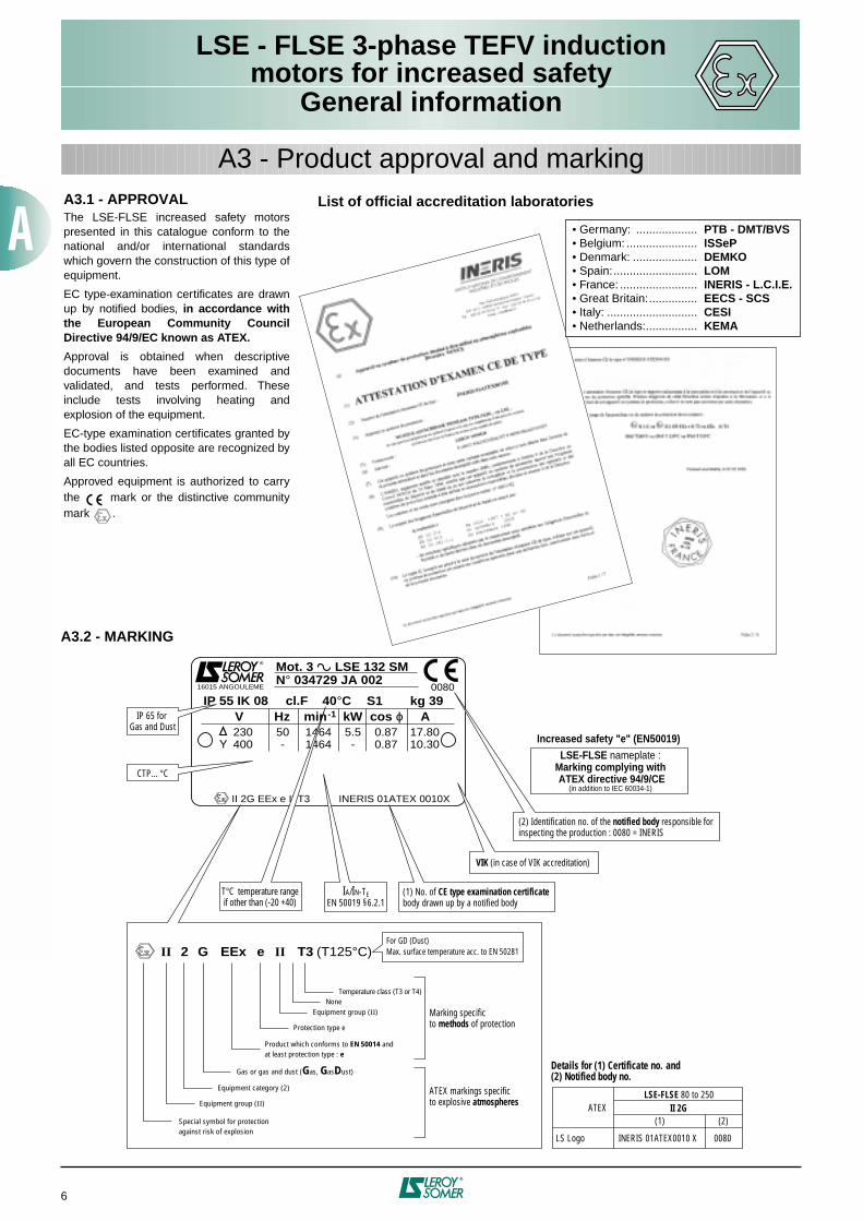
A3.1 - APPROVAL
The LSE-FLSE increased safety motorspresented in this catalogue conform to thenational and/or international standardswhich govern the construction of this type ofequipment.
EC type-examination certificates are drawnup by notified bodies,
in accordance withthe European Community CouncilDirective 94/9/EC known as ATEX.
Approval is obtained when descriptivedocuments have been examined andvalidated, and tests performed. Theseinclude tests involving heating andexplosion of the equipment.
EC-type examination certificates granted bythe bodies listed opposite are recognized byall EC countries.
Approved equipment is authorized to carrythe mark or the distinctive communitymark .
A3 - Product approval and marking
A3.2 - MARKING
N° 034729 JA 002Mot. 3 LSE 132 SM
IP 55 IK 08 cl.F 40°C S1 kg 39008016015 ANGOULEME
V Hz min-1 kW cos ϕ A230400
50-
14641464
5.5-
0.870.87
17.8010.30
II 2G EEx e II T3 INERIS 01ATEX 0010X
IP 65 for Gas and Dust
CTP... °C
T°C temperature rangeif other than (-20 +40)
IA/IN-TEEN 50019 §6.2.1
VIK (in case of VIK accreditation)
Details for (1) Certificate no. and(2) Notified body no.
ATEX
LS Logo INERIS 01ATEX0010 X 0080
(1)II 2G
LSE-FLSE 80 to 250
(2)
Marking specificto methods of protection
For GD (Dust)Max. surface temperature acc. to EN 50281
(2) Identification no. of the notified body responsible forinspecting the production : 0080 = INERIS
(1) No. of CE type examination certificate body drawn up by a notified body
LSE-FLSE nameplate :Marking complying with ATEX directive 94/9/CE
(in addition to IEC 60034-1)
Increased safety "e" (EN50019)
II
Special symbol for protectionagainst risk of explosion
Equipment group (II)
2 G EEx e II T3 (T125°C)
Equipment category (2)
Gas or gas and dust (Gas, GasDust)
Protection type e
Equipment group (II)None
Temperature class (T3 or T4)
ATEX markings specificto explosive atmospheres
Product which conforms to EN 50014 andat least protection type : e
List of official accreditation laboratories
• Germany: ................... PTB - DMT/BVS• Belgium: ...................... ISSeP• Denmark: .................... DEMKO• Spain:.......................... LOM• France: ........................ INERIS - L.C.I.E.• Great Britain:............... EECS - SCS• Italy: ............................ CESI• Netherlands:................ KEMA
LSE - FLSE 3-phase TEFV inductionmotors for increased safety
General information
7
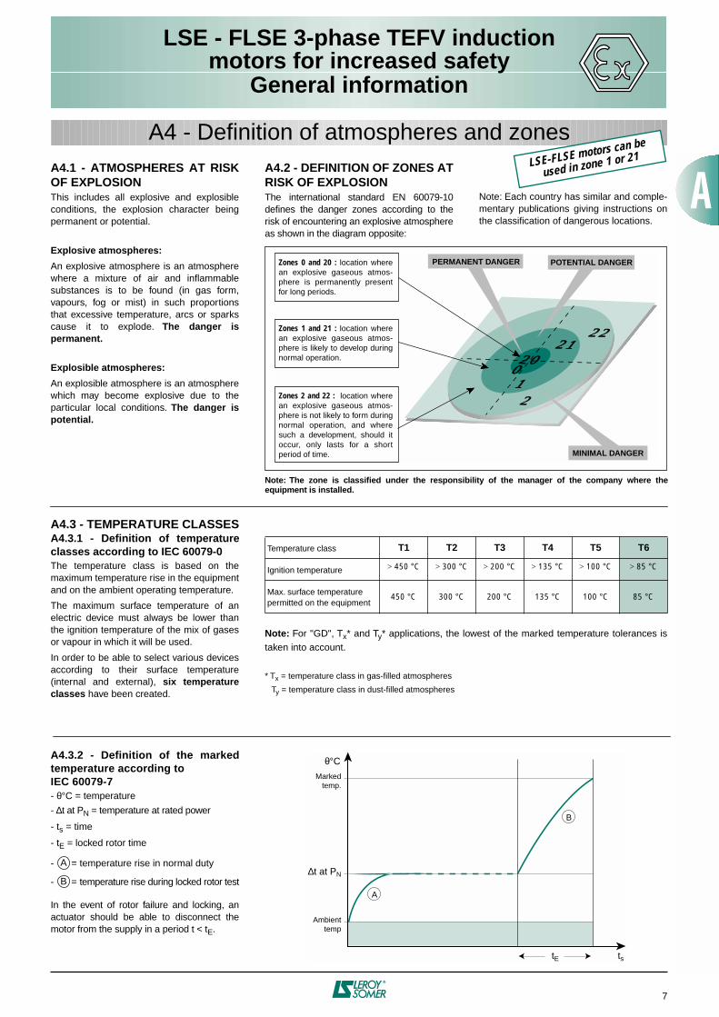
A4.1 - ATMOSPHERES AT RISKOF EXPLOSION
This includes all explosive and explosibleconditions, the explosion character beingpermanent or potential.
Explosive atmospheres:
An explosive atmosphere is an atmospherewhere a mixture of air and inflammablesubstances is to be found (in gas form,vapours, fog or mist) in such proportionsthat excessive temperature, arcs or sparkscause it to explode.
The danger ispermanent.
Explosible atmospheres:
An explosible atmosphere is an atmospherewhich may become explosive due to theparticular local conditions.
The danger ispotential.
A4 - Definition of atmospheres and zones
Note: The zone is classified under the responsibility of the manager of the company where theequipment is installed.
A4.3 - TEMPERATURE CLASSES
A4.3.1 - Definition of temperatureclasses according to IEC 60079-0
The temperature class is based on themaximum temperature rise in the equipmentand on the ambient operating temperature.
The maximum surface temperature of anelectric device must always be lower thanthe ignition temperature of the mix of gasesor vapour in which it will be used.
In order to be able to select various devicesaccording to their surface temperature(internal and external),
six temperatureclasses
have been created.
Note:
For "GD", T
x
* and T
y
* applications, the lowest of the marked temperature tolerances istaken into account.
* T
x
= temperature class in gas-filled atmospheres
T
y
= temperature class in dust-filled atmospheres
Temperature class
T1 T2 T3 T4 T5 T6
Ignition temperature
>
450 °C
>
300 °C
>
200 °C
>
135 °C
>
100 °C
>
85 °C
Max. surface temperaturepermitted on the equipment
450 °C 300 °C 200 °C 135 °C 100 °C 85 °C
A4.2 - DEFINITION OF ZONES ATRISK OF EXPLOSION
The international standard EN 60079-10defines the danger zones according to therisk of encountering an explosive atmosphereas shown in the diagram opposite:
Note: Each country has similar and comple-mentary publications giving instructions onthe classification of dangerous locations.
2221
2012
0
PERMANENT DANGER POTENTIAL DANGER
MINIMAL DANGER
Zones 0 and 20 : location where an explosive gaseous atmos-phere is permanently present for long periods.
Zones 1 and 21 : location where an explosive gaseous atmos-phere is likely to develop during normal operation.
Zones 2 and 22 : location where an explosive gaseous atmos-phere is not likely to form during normal operation, and where such a development, should it occur, only lasts for a short period of time.
A4.3.2 - Definition of the markedtemperature according toIEC 60079-7
-
θ
°C = temperature
-
∆
t at P
N
= temperature at rated power
- t
s
= time
- t
E
= locked rotor time
- = temperature rise in normal duty
- = temperature rise during locked rotor test
In the event of rotor failure and locking, anactuator should be able to disconnect themotor from the supply in a period t < t
E
.
A
B
tstE
Ambient temp
∆t at PN
Markedtemp.
θ°C
B
A
LSE-FLSE motors can be
used in zone 1 or 21

8
LSE - FLSE 3-phase TEFV inductionmotors for increased safety
General information
A5 - Definition of "Index of Protection" (IP/IK)
Indices of protection of electrical equipment enclosures
IP0
1
2
3
4
5
Tests Definition IP Tests Definition IK Tests Definition
First number :Protection against solid objects Mechanical protection
∅ 50 mm
∅ 12 mm
No protection
Protected againstsolid objects ofover 12 mm(eg : finger)
Protected against solid objects of over 50mm (eg : accidentalhand contact)
Protected againstsolid objects ofover 2.5 mm(eg : tools, wire)
∅ 2.5 mm
Protected againstsolid objects of over 1 mm (eg : small tools,thin wire)
∅ 1 mm
Second number:Protection against liquids
0 No protection 00 No protection
1
15°
2
3
4
60°
5
6
7
8 ..m
0.15
m
1 m
Protected against dust (no depositsof harmful material)
Totally protected against any dustpenetration
Protected againstthe effects ofprolonged immersionat depth
Protected againstthe effects ofimmersion ofdepths of between0.15 and 1 m
Protected againstjets of water comparable to heavy seas
Protected againstjets of water from all directions
Protected againstwater splashesfrom all directions
Protected againstrain falling at upto 60° fromthe vertical
Protected againstwater drippingup to 15° fromthe vertical
Protected againstvertically drippingwater(condensation)
01 Impact energy:0.15 J
02 Impact energy:0.20 J
03 Impact energy:0.37 J
05 Impact energy:0.70 J
07 Impact energy:2 J
09 Impact energy:10 J
150 g
10 cm
250 g
15 cm
250 g
20 cm
250 g40 cm
0.5 kg40 cm
2.5 kg40 cm
. . m
6
200 g
10 cm
350 g
20 cm
04
06
081.25 kg
40 cm
10 Impact energy:20 J
5 kg40 cm
Impact energy:5 J
Impact energy:1 J
Impact energy:0.50 J
Example:
IP 55 machine
IP : Index of protection
5. : Machine protected against dust and accidental contact.Test result: no dust enters in harmful quantities, no risk of direct contactwith rotating parts. The test will last for 2 hours.
.5 : Machine protected against jets of water from all directions from hoses at 3 m distancewith a flow rate of 12.5 l/min at 0.3 bar.The test will last for 3 minutes. Test result: no damage from water projected onto themachine.
LSE-FLSE are IP 55 and IK 08
as standard

LSE - FLSE 3-phase TEFV inductionmotors for increased safety
Construction
9
B1 - Components
B1.1 - DESCRIPTION OF LSE - FLSE 3-PHASE MOTORS
B1.2 - EXTERNAL FINISH
The standard paint colour for the LSE-FLSE range is:
Component Materials Remarks
Finned housing Aluminium alloy or cast iron - with integral or screw-on feet, or without feet• 4 or 6 fixing holes for housings with feet• lifting rings
- earth terminal
Stator Insulated low-carbon magnetic steellaminationsInsulated electroplated copper
- low carbon content guarantees long-term lamination pack stability- welded packs- semi-enclosed slots- class F insulation
Rotor Insulated low-carbon magnetic steellaminationsAluminium
- inclined cage bars- rotor cage pressure die-cast in aluminium (or alloy for special applications)- shrink-fitted or keyed to shaft- rotor balanced dynamically, class N - 1/2 key
Shaft Steel - for frame size < 132 :• shaft end fitted with screw and washer• closed keyway
- for frame size
≥
132:• tapped hole• open keyway
End shields Aluminium alloy - LSE series drive end and non drive end frame sizes 63 - 71- LSE series non drive end frame sizes 80 - 90
Cast iron - LSE series frame sizes 80 - 90 drive end (optional for 80 and 90 at non drive end)- LSE series frame size
≥
100• all FLSE series frame sizes
Bearings - ball bearings- bearings preloaded at non drive end
Labyrinth seal Lipseals
Plastic or steelSynthetic rubber
- sealed with gaskets- labyrinth seals or deflector at drive end or non drive end
Fan Composite materialor aluminium alloy
- 2 directions of rotation: straight blades
Fan cover Pressed steel - fitted, on request, with a drip cover for operation in vertical position, shaft end facing down
Terminal box Aluminium alloyor cast iron
- IP 55 or IP 65 for "GD" applications- can be turned, opposite the feet- fitted with a terminal block with 6 terminals certified EEx e safety- terminal box supplied fitted with certified EEx e safety cable anchor glands- 1 earth terminal in each terminal box
8
6
91
2
3
10
7
4
5
RAL 2004
1
2
3
4
5
6
7
8
9
10

LSE - FLSE 3-phase TEFV inductionmotors for increased safety
Construction
10
B2 - Mains connection
B2.1 - TERMINAL BOX ANDCABLE GLAND POSITIONS
Placed as standard on the top of the motor,the terminal box has IP 55 (G) or IP 65 (GD)protection and is fitted with a cable gland(see table in B2.2).
The standard position of the cable gland ison the right, seen from the drive end(position A1) but, owing to the symmetricalconstruction of the box, it can usually beplaced in any of the 4 directions.
▼
Positions of the terminal box in relation to the drive end
(motor in IM 1001 position)
▼
Positions of the cable gland in relation to the drive end
2
4
13
A
BD
Standardposition
Standardpositionas supplied(can be oriented)
B2.2 - CABLE GLAND FOR RATED SUPPLY VOLTAGE OF 400V
CMDEL :
cable anchor glands approved EEx e
.: cable gland made of brass.
Frame sizeSingle speed motor Cable gland for accessories:
PTO / PTF / etcD.O.L. starting Y
∆
starting
80
CMDEL ISO M20 x 1.5 - CMDEL ISO M16 x 1.5
90
CMDEL ISO M20 x 1.5 - CMDEL ISO M16 x 1.5
100
CMDEL ISO M20 x 1.5 2 x CMDEL ISO 20 CMDEL ISO M16 x 1.5
112 - 132 S
CMDEL ISO M20 x 1.5 2 x CMDEL ISO 20 CMDEL ISO M16 x 1.5
132 M
CMDEL ISO M25 x 1.5 2 x CMDEL ISO 25 CMDEL ISO M16 x 1.5
160 / 180 MR
2 x CMDEL ISO M25 x 1.5 2 x CMDEL ISO 25 CMDEL ISO M16 x 1.5
180
2 x CMDEL ISO M32 x 1.5 2 x CMDEL ISO 25 CMDEL ISO M16 x 1.5
200
2 x CMDEL ISO M32 x 1.5 2 x CMDEL ISO 25 CMDEL ISO M16 x 1.5
225
2 x CMDEL ISO M40 x 1.5 2 x CMDEL ISO 32 CMDEL ISO M16 x 1.5
Cable size and diameter of drill holes on brass cable gland mounting plates
For frame sizes 63, 71, 250 and 280: please consult Leroy-Somer.
Type of cable glandCable size
min. cable Ø (mm) max. cable Ø (mm)
CMDEL ISO M16 x 1.5
6 11
CMDEL ISO M20 x 1.5
7.5 13
CMDEL ISO M25 x 1.5
12.5 18
CMDEL ISO M32 x 1.5
17.5 25
CMDEL ISO M40 x 1.5
24.5 33.5
Ø m
ax.
Ø m
in.
Note:
for FLSE motors, only position
A
ispossible.
Note:
position
2
is not recommended for FFor FT flange mounted motors.

LSE 3-phase TEFV inductionmotors for increased safety
Electrical characteristics
11
PAGES
2 poles - 3000 min
–1
- EEx e II T3
.......................................................
12
2 poles - 3000 min
–1
- EEx e II T3 VIK*
..............................................
13
4 poles - 1500 min
–1
- EEx e II T3
.......................................................
14
4 poles - 1500 min
–1
- EEx e II T3 VIK*
..............................................
15
6 poles - 1000 min
–1
- EEx e II T3
.......................................................
16
6 poles - 1000 min
–1
- EEx e II T3 VIK*
..............................................
17
2 poles - 3000 min
–1
- EEx e II T4
.......................................................
18
4 poles - 1500 min
–1
- EEx e II T4
.......................................................
19
6 poles - 1000 min
–1
- EEx e II T4
.......................................................
20
*
VIK: extension of EN 50019 requirements to particular specifications intendedfor German manufacturing companies:
- ranges with special power ratings according to frame size (DIN 42673)- increased duration t
E
(
≥
7 sec)
- 2
nd
nameplate in the terminal box- ISO M25 cable gland from frame size 80 mm upwards- oil-resistant seals- terminal blocks not split from frame size 160 mm upwards
Other polarities (1 or 2-speed): please consult Leroy-Somer.
C1 - Selection data: LSE aluminium motors

LSE 3-phase TEFV inductionmotors for increased safety
Electrical characteristics
12
C1 - Selection data: LSE aluminium motors
MAINS SUPPLY 380 / 400 / 415 V 50 Hz
Ratedvoltage
Rated power
at 50 HzRated speed
Ratedtorque
Rated current
Powerfactor Efficiency
Starting current / Rated current
Starting torque / Rated torque
Maximum torque / Rated torque
Lockedrotortime
Momentof inertia Weight
Type
U
N
V
P
N
kW
N
N
min
-1
M
N
N.m
I
N
A
Cos
ϕ η
%
I
D
/I
N
M
D
/M
N
M
M
/M
N
t
E
s
J
kg.m
2
IM B3kg
380 0.25
LSE 63
400 0.25
415 0.25
380 0.37
LSE 71
400 0.37
415 0.37
380 0.55
LSE 71
400 0.55
415 0.55
380 0.75 2860 2.5 1.7 0.86 79.2 6.8 2.7 2.8 8.3 0.0009 9.7
LSE 80 L
400 0.75 2872 2.5 1.6 0.84 79.4 7.1 2.9 3 7.6 0.0009 9.7
415 0.75 2890 2.5 1.6 0.81 79.5 7.4 3.1 3.2 7 0.0009 9.7
380 1.1 2860 3.75 2.4 0.89 78 7.1 2.9 2.8 12.6 0.0011 11.3
LSE 80 L
400 1.1 2870 3.75 2.3 0.86 78.5 7.5 3.2 3.1 11.1 0.0011 11.3
415 1.1 2885 3.75 2.3 0.84 78.7 7.9 3.4 3.3 10 0.0011 11.3
380 1.5 2845 5 3.1 0.90 82.3 7 2.8 2.8 11.6 0.0017 14
LSE 90 S
400 1.5 2860 5 2.9 0.88 83.6 7.5 3.1 3.1 10.2 0.0017 14
415 1.5 2880 5 2.9 0.87 83.5 8.2 3.5 3.5 8.5 0.0017 14
380 2.2 2869 7.5 4.4 0.89 85.5 6.2 2.1 2.7 11 0.0022 17.8
LSE 90 L
400 2.2 2884 7.5 4.2 0.87 85.7 6.7 2.4 3.1 9.4 0.0022 17.8
415 2.2 2895 7.5 4.1 0.87 85.8 7.5 2.6 3.3 7.5 0.0022 17.8
380 3 2871 10.1 5.9 0.90 85.8 5 2.1 2.1 9.7 0.0029 24
LSE 100 L
400 3 2887 10.1 5.6 0.89 86.2 5.5 2.3 2.3 8 0.0029 24
415 3 2903 10.1 5.6 0.87 86.3 5.9 2.5 2.5 7 0.0029 24
380 4 2920 13.5 7.4 0.92 88.5 6.9 1.8 2.7 9.9 0.0088 39
LSE 112 MU
400 4 2928 13.5 7.1 0.92 88.6 7.5 2 3 8.4 0.0088 39
415 4 2935 13.5 6.9 0.91 88.6 8.2 2.2 3.2 7 0.0088 39
380 5.5 2916 18.6 10.2 0.92 89.4 5.9 1.5 2.4 10.4 0.016 49
LSE 132 SM
400 5.5 2926 18.6 9.7 0.91 89.8 6.5 1.7 2.6 8.6 0.016 49
415 5.5 2933 18.6 9.4 0.90 89.9 7.2 1.8 2.8 7 0.016 49
380 7.5 2921 25.4 13.6 0.92 90.2 6.25 1.6 2.4 10.3 0.018 54
LSE 132 SM
400 7.5 2929 25.4 13.1 0.92 90.4 6.9 1.7 2.6 8.5 0.018 54
415 7.5 2936 25.4 12.6 0.91 90.6 7.6 1.9 2.9 7 0.018 54
380 11 2927 36 19.8 0.93 90.2 6.4 1.5 2.4 10.1 0.023 72
LSE 160 MP
400 11 2935 36 19.1 0.92 90.5 7.1 1.7 2.6 8.2 0.023 72
415 11 2941 36 18.5 0.91 90.6 7.7 1.8 2.8 7 0.023 72
380 15 2925 49 28 0.90 90.6 7.1 2.3 2.8 8.2 0.044 88
LSE 160 L
400 15 2933 48.8 26.7 0.89 91 7.8 2.6 3.1 6.8 0.044 88
415 15 2941 48.7 26 0.88 91.2 8.3 2.8 3.4 6 0.044 88
380 18.5 2921 60.5 34 0.91 90.8 7.1 2.3 2.6 6.8 0.052 99
LSE 180 MT
400 18.5 2930 60.3 32.5 0.90 91.3 7.8 2.6 2.9 5.7 0.052 99
415 18.5 2939 60.1 31.6 0.89 91.6 8.3 2.8 3.2 5 0.052 99
380 22 2939 71.5 38.6 0.93 93.5 7.7 2.3 3 13.7 0.089 154
LSE 200 LT
400 22 2946 71.3 36.8 0.92 93.7 8.5 2.6 3.3 11.2 0.089 154
415 22 2952 71.2 36 0.91 93.8 9 2.8 3.5 10 0.089 154
380 30 2951 97.1 53.1 0.92 93.3 7.1 2.4 2.8 12.3 0.12 180
LSE 200 L
400 30 2956 96.9 50.9 0.91 93.5 7.8 2.7 3.1 10.2 0.12 180
415 30 2961 96.8 49.5 0.90 93.7 8.3 2.9 3.4 9 0.12 180
380 37 2942 120 65.6 0.92 93.2 7.1 2.4 2.8 6.8 0.14 200
LSE 225 MT
400 37 2951 120 62.7 0.91 93.6 7.8 2.7 3.1 5.7 0.14 200
415 37 2957 120 60.9 0.90 93.9 8.3 3 3.4 5 0.14 200
380 45
LSE 250 MZ
400 45
415 45
380 55
LSE 280 SC
400 55
415 55
EEx e
II
T32poles3000 min-1
Please consult Leroy-Somer
Please consult Leroy-Somer

LSE 3-phase TEFV inductionmotors for increased safety
Electrical characteristics
13
MAINS SUPPLY 380 / 400 / 420 V 50 Hz
Ratedvoltage
Rated power
at 50 HzRated speed
Ratedtorque
Rated current
Powerfactor Efficiency
Starting current / Rated current
Starting torque / Rated torque
Maximum torque / Rated torque
Lockedrotortime
Momentof inertia Weight
Type
U
N
V
P
N
kW
N
N
min
-1
M
N
N.m
I
N
A
Cos
ϕ η
%
I
D
/I
N
M
D
/M
N
M
M
/M
N
t
E
s
J
kg.m
2
IM B3kg
380 1.5 2845 5 3.1 0.90 82.3 7 2.8 2.8 11.7 0.0017 14
LSE 90 S
400 1.5 2865 5 3 0.87 82.8 7.5 3.1 3.1 10.4 0.0017 14
420 1.5 2886 5 2.9 0.85 83.4 8.3 3.6 3.6 8.5 0.0017 14
380 1.85 2881 6.3 3.7 0.88 86.1 6.4 2.2 2.6 9.3 0.0022 17.8
LSE 90 L
400 1.85 2890 6.3 3.6 0.86 86.2 6.5 2.4 3 9 0.0022 17.8
420 1.85 2903 6.3 3.5 0.85 86.2 6.7 2.7 3.5 8.5 0.0022 17.8
380 2.5 2859 8.5 4.9 0.91 84.5 5.4 2.5 2.5 11.2 0.0026 22
LSE 100 L
400 2.5 2865 8.5 4.8 0.89 94.7 5.8 2.7 2.7 9.7 0.0026 22
420 2.5 2890 8.5 4.7 0.87 84.9 6.2 3.1 3.1 8.5 0.0026 22
380 3.3 2915 11.2 6.5 0.95 82.1 8.9 2.9 3.8 11.4 0.0076 35
LSE 112 MG
400 3.3 2925 11.2 6.3 0.93 82.4 9.2 3.2 4.1 10.6 0.0076 35
420 3.3 2935 11.2 6.0 0.91 82.7 10 3.5 4.6 9 0.0076 35
380 4.6 2925 15.6 8.5 0.91 89.8 6.2 1.6 2.4 11.7 0.016 49
LSE 132 SM
400 4.6 2932 15.6 8.2 0.90 90 6.8 1.7 2.6 9.7 0.016 49
420 4.6 2939 15.6 7.9 0.90 90.2 7.5 1.9 2.9 8 0.016 49
380 5.5 2929 18.6 10.1 0.91 90.2 6.35 1.5 2.4 11.5 0.018 54
LSE 132 SM
400 5.5 2940 18.6 9.9 0.89 90 7.2 1.9 3 9 0.018 54
420 5.5 2957 18.6 9.7 0.87 89.8 7.6 2.4 3.7 8 0.018 54
380 7.5 2933 25.4 13.6 0.92 90.8 6.6 1.6 2.4 13.4 0.023 72
LSE 160 MP
400 7.5 2940 25.4 13 0.91 91 7.3 1.8 2.7 11 0.023 72
420 7.5 2947 25.4 12.5 0.91 91.2 8.1 1.9 3 9 0.023 72
380 10 2930 34 18.2 0.92 90.9 6.9 1.6 2.5 10.1 0.023 72
LSE 160 MP
400 10 2937 34 17.5 0.92 91 7.5 1.8 2.7 8.6 0.023 72
420 10 2945 34 16.7 0.91 91.1 8.3 2 3.1 7 0.023 72
380 12.5 2944 40.5 23.3 0.89 91.4 8.5 2.7 3.4 13.8 0.044 88
LSE 160 L
400 12.5 2950 40.5 22.4 0.88 91.6 9.3 3.1 3.8 11.6 0.044 88
420 12.5 2957 40.4 21.8 0.86 91.7 10 3.4 4.2 10 0.044 88
380 15 2943 48.7 27.6 0.90 91.7 8.4 2.9 3.3 13.9 0.052 99
LSE 180 MT
400 15 2950 48.6 26.5 0.89 91.9 9.3 3.2 3.6 11.6 0.052 99
420 15 2956 48.5 25.8 0.87 92 10 3.6 4 10 0.052 99
380 20 2949 64.8 34.9 0.93 93.6 8.3 2.5 3.3 14.5 0.089 154
LSE 200 LT
400 20 2954 64.7 33.5 0.92 93.7 9.2 2.8 3.6 11.8 0.089 154
420 20 2959 64.5 32.2 0.91 93.7 10 3.2 4 10 0.089 154
380 24 2965 77.3 42.8 0.91 93.7 8.4 3 3.5 13.9 0.120 180
LSE 200 L
400 24 2968 77.2 41 0.90 93.8 9.3 3.4 3.9 11.6 0.120 180
420 24 2971 77.1 40 0.88 93.8 10 3.8 4.3 10 0.120 180
380 28 2959 90.4 49.5 0.92 93.5 8.4 2.9 3.4 13.9 0.140 200
LSE 225 MT
400 28 2964 90.2 47.4 0.91 93.7 9.3 3.3 3.8 11.6 0.140 200
420 28 2969 90.1 45.6 0.90 93.8 10 3.6 4.1 10 0.140 200
380 36
LSE 250 MZ
400 36
420 36
380 47
LSE 280 SC
400 47
420 47
C1 - Selection data: LSE aluminium motors
2poles3000 min-1
EEx e
II
T3 VIK
Please consult Leroy-Somer

LSE 3-phase TEFV inductionmotors for increased safety
Electrical characteristics
14
C1 - Selection data: LSE aluminium motors
MAINS SUPPLY 380 / 400 / 415 V 50 Hz
Ratedvoltage
Rated power
at 50 HzRated speed
Ratedtorque
Rated current
Powerfactor Efficiency
Starting current / Rated current
Starting torque / Rated torque
Maximum torque / Rated torque
Lockedrotortime
Momentof inertia Weight
Type
U
N
V
P
N
kW
N
N
min
-1
M
N
N.m
I
N
A
Cos
ϕ η
%
I
D
/I
N
M
D
/MN MM/MN tEs
Jkg.m2
IM B3kg
380 0.25
LSE 63 400 0.25
415 0.25
380 0.37
LSE 71 400 0.37
415 0.37
380 0.55
LSE 71 400 0.55
415 0.55
380 0.75 1415 5 2 0.76 74 5.32 2 2.1 11.9 0.0024 10.9
LSE 80 L 400 0.75 1430 5 2 0.72 74 5.6 2.2 2.3 10.7 0.0024 10.9
415 0.75 1430 5 2 0.70 74 5.8 2.4 2.6 10 0.0024 10.9
380 1.1 1435 7.5 2.5 0.84 80.7 4.7 1.5 1.8 9.9 0.0032 13.5
LSE 90 S 400 1.1 1443 7.5 2.4 0.83 81.5 5.2 1.6 2 8.1 0.0032 13.5
415 1.1 1449 7.5 2.3 0.81 81.7 5.6 1.8 2.2 7 0.0032 13.5
380 1.5 1445 10 3.7 0.79 78 6.1 1.7 1.9 8 0.0037 15.2
LSE 90 L 400 1.5 1450 10 3.7 0.75 78 6.4 1.7 2 7.2 0.0037 15.2
415 1.5 1455 10 3.8 0.72 77 6.5 1.9 2.2 7 0.0037 15.2
380 2.2 1427 15 4.6 0.88 83.3 5.1 1.9 2 13.7 0.0055 22.5
LSE 100 L 400 2.2 1444 15 4.5 0.85 83.5 5.8 2.1 2.2 10.6 0.0055 22.5
415 2.2 1458 15 4.6 0.78 84.4 6.3 2.3 2.4 9 0.0055 22.5
380 3 1412 20 6.4 0.86 81.9 5.1 2 2 9.4 0.0073 27.5
LSE 100 LR 400 3 1423 20 6.2 0.85 83 5.2 2 2.1 9 0.0073 27.5
415 3 1433 20 5.9 0.84 83.8 5.9 2.2 2.3 7 0.0073 27.5
380 4 1453 27.2 7.9 0.88 86.9 6 1.8 2 11.8 0.014 36.5
LSE 112 MU 400 4 1458 27.2 7.7 0.86 86.9 6.7 2 2.1 9.5 0.014 36.5
415 4 1466 27.2 7.7 0.82 87.4 7.3 2.2 2.4 8 0.014 36.5
380 5.5 1451 37.4 10.5 0.91 87.9 6 1.6 2.2 12.2 0.019 54.7
LSE 132 SM 400 5.5 1464 37.4 10.3 0.87 88.4 6.5 1.8 2.5 10.4 0.019 54.7
415 5.5 1471 37.4 10.7 0.81 87.7 7 1.9 2.7 9 0.019 54.7
380 7.5 1455 50 15 0.88 86 7.9 1.7 2.4 7.6 0.023 59.9
LSE 132 M 400 7.5 1457 50 14.8 0.85 86 8.4 1.9 2.6 6.8 0.023 59.9
415 7.5 1460 50 14.6 0.83 86 8.9 2.1 2.8 6 0.023 59.9
380 11 1465 74.7 22.1 0.84 89.2 7.6 2.2 2.9 8 0.035 78
LSE 160 MR 400 11 1468 74.7 22 0.82 89 8.1 2.4 3.1 7.1 0.035 78
415 11 1472 74.7 21.7 0.80 88.8 8.8 2.6 3.4 6 0.035 78
380 15 1449 98.9 29.4 0.87 89.2 6.5 2.3 2.7 11.5 0.085 100
LSE 160 L 400 15 1455 98.5 28 0.86 89.8 7.3 2.6 3.2 9.1 0.085 100
415 15 1460 98.1 27.2 0.85 90.1 7.8 2.9 3.5 8 0.085 100
380 18.5 1453 122 35.2 0.88 90.7 7.2 2.7 3 7.5 0.096 112
LSE 180 MR 400 18.5 1458 121 34 0.86 91.2 7.9 3 3.4 6.2 0.096 112
415 18.5 1463 121 33.2 0.85 91.3 8.8 3.2 3.7 5 0.096 112
380 22 1460 144 41.5 0.88 91.6 6.5 2.7 2.7 10.6 0.151 165
LSE 180 LU 400 22 1464 144 39.7 0.87 91.9 7.1 3 3 9 0.151 165
415 22 1468 143 39.1 0.85 92.1 7.5 3.3 3.2 8 0.151 165
380 30 1468 195 57.2 0.86 92.7 6 2.5 2.4 13.6 0.240 205
LSE 200 L 400 30 1472 195 54.8 0.85 93 6.6 2.7 2.6 11.2 0.240 205
415 30 1475 194 53.3 0.84 93.2 7 3 2.9 10 0.240 205
380 37 1467 241 70.4 0.86 92.9 6 2.7 2.6 13.6 0.290 235
LSE 225 SR 400 37 1471 240 68.2 0.84 93.2 6.6 3 2.9 11.2 0.290 235
415 37 1474 240 66.5 0.83 93.3 7 3.2 3.1 10 0.290 235
380 45
LSE 250 ME 400 45
415 45
380 55
LSE 280 SC 400 55
415 55
EEx e II T34poles1500 min-1
Please consult Leroy-Somer
Please consult Leroy-Somer

LSE 3-phase TEFV inductionmotors for increased safety
Electrical characteristics
15
C1 - Selection data: LSE aluminium motors
MAINS SUPPLY 380 / 400 / 420 V 50 Hz
Ratedvoltage
Rated power
at 50 HzRated speed
Ratedtorque
Rated current
Powerfactor Efficiency
Starting current / Rated current
Starting torque / Rated torque
Maximum torque / Rated torque
Lockedrotor time
Momentof inertia Weight
TypeUNV
PNkW
NN
min-1MNN.m
INA
Cos ϕ η%
ID/IN MD/MN MM/MN tEs
Jkg.m2
IM B3kg
380 1 1444 6.8 2.3 0.83 81.6 5.2 1.7 2 11.7 0.0032 13.5
LSE 90 S 400 1 1450 6.8 2.3 0.81 81.7 5.8 1.9 2.3 9.4 0.0032 13.5
420 1 1456 6.8 2.2 0.78 81.9 6.3 2.1 2.5 8 0.0032 13.5
380 1.35 1444 9.2 3 0.83 83.5 6.3 1.9 2.2 10.5 0.0037 15.2
LSE 90 L 400 1.35 1450 9.2 2.9 0.81 83.5 6.6 2.1 2.4 9.6 0.0037 15.2
420 1.35 1456 9.2 2.9 0.78 83.5 6.8 2.4 2.7 9 0.0037 15.2
380 1.85 1445 12.6 4.1 0.81 83.9 6.3 2.3 2.4 14.2 0.0055 22.5
LSE 100 L 400 1.85 1451 12.6 4 0.78 84 7 2.6 2.7 11.5 0.0055 22.5
420 1.85 1457 12.6 4 0.76 84 7.5 2.9 3 10 0.0055 22.5
380 2.5 1428 16.9 5.8 0.82 80.5 5.4 2.5 2.5 13.2 0.0067 24.9
LSE 100 L 400 2.5 1436 16.9 5.6 0.79 81.2 5.8 2.7 2.7 11.4 0.0067 24.9
420 2.5 1444 16.9 5.5 0.77 81.7 6.2 3 3.1 10 0.0067 24.9
380 3.6 1450 24.4 7.3 0.87 86.3 6.6 1.9 2.7 13.6 0.014 36.5
LSE 112 MU 400 3.6 1455 24.4 7.1 0.84 86.4 7.1 2 2.9 11.8 0.014 36.5
420 3.6 1460 24.4 7 0.82 86.5 7.7 2.1 3 10 0.014 36.5
380 5 1450 33.9 10 0.89 85.4 8 2.3 2.8 13.2 0.019 54.7
LSE 132 SM 400 5 1456 33.9 9.7 0.87 85.5 8.5 2.6 3.1 11.7 0.019 54.7
420 5 1462 33.9 9.4 0.85 85.6 9.2 2.8 3.4 10 0.019 54.7
380 6.8 1445 46.2 13.5 0.90 84.8 7.3 2.8 2.6 12.2 0.023 59.9
LSE 132 M 400 6.8 1457 46.2 13 0.88 84.9 7.9 3.1 2.8 10.4 0.023 59.9
420 6.8 1460 46.2 12.6 0.87 85 8.5 3.4 3 9 0.023 59.9
380 10 1465 67.9 20.4 0.84 88.6 9.3 2.9 3.7 9.2 0.035 78
LSE 160 MR 400 10 1469 67.9 20.5 0.81 88 9.5 3.2 4 8.9 0.035 78
420 10 1473 67.9 20.7 0.76 87.2 10 3.6 4.5 8 0.035 78
380 13.5 1457 88.5 26.2 0.87 90 7.2 2.5 3 13.9 0.085 100
LSE 160 L 400 13.5 1461 88.2 25.4 0.85 90.4 7.8 2.8 3.3 11.9 0.085 100
420 13.5 1465 88 24.7 0.83 90.5 8.5 3.1 3.6 10 0.085 100
380 15 1466 97.7 29.2 0.85 91.7 8.7 3.3 3.8 9.3 0.096 112
LSE 180 MR 400 15 1469 97.5 28.4 0.83 91.8 9.4 3.7 4.2 7.9 0.096 112
420 15 1472 97.3 28.1 0.80 91.7 10 4 4.6 7 0.096 112
380 17.5 1472 114 33.9 0.85 92.3 7.9 3.4 3.4 13.8 0.151 165
LSE 180 LU 400 17.5 1475 113 32.5 0.84 92.4 8.6 3.8 3.8 11.7 0.151 165
420 17.5 1478 113 32.1 0.81 92.4 9.3 4.2 4.2 10 0.151 165
380 24 1478 155 46.4 0.84 93.5 7.4 3 3 13.5 0.240 205
LSE 200 L 400 24 1481 155 44.6 0.83 93.6 8 3.4 3.3 11.5 0.240 205
420 24 1483 155 44 0.81 93.6 8.6 3.8 3.7 10 0.240 205
380 30 1477 194 58.7 0.83 93.6 7.3 3.3 3.2 13.2 0.290 235
LSE 225 SR 400 30 1479 194 57.1 0.81 93.6 7.9 3.7 3.6 11.3 0.290 235
420 30 1481 194 55.8 0.79 93.6 8.4 4.1 4 10 0.290 235
380 36 1468 234 69.2 0.85 93 6.2 2.7 2.7 13.9 0.290 235
LSE 225 MR 400 36 1471 234 66.3 0.84 93.3 6.8 3 3 11.5 0.290 235
420 36 1474 233 64.6 0.82 93.4 7.3 3.3 3.3 10 0.290 235
380 44
LSE 250 ME 400 44
420 44
380 58
LSE 280 SC 400 58
420 58
4poles1500 min-1
EEx e II T3 VIK
Please consult Leroy-Somer

LSE 3-phase TEFV inductionmotors for increased safety
Electrical characteristics
16
C1 - Selection data: LSE aluminium motors
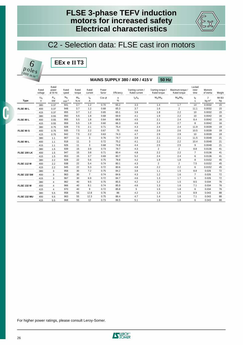
EEx e II T3
MAINS SUPPLY 380 / 400 / 415 V 50 Hz
Ratedvoltage
Rated power
at 50 HzRated speed
Ratedtorque
Rated current
Powerfactor Efficiency
Starting current / Rated current
Starting torque / Rated torque
Maximum torque / Rated torque
Lockedrotortime
Momentof inertia Weight
TypeUNV
PNkW
NN
min-1MNN.m
INA
Cos ϕ η%
ID/IN MD/MN MM/MN tEs
Jkg.m2
IM B3kg
380 0.18
LSE 71 400 0.18
415 0.18
380 0.25
LSE 71 400 0.25
415 0.25
380 0.37 941 3.7 1.2 0.70 65.2 3.3 1.4 1.7 14 0.0032 9.7
LSE 80 L 400 0.37 948 3.7 1.2 0.68 65.3 3.7 1.6 2 11.2 0.0032 9.7
415 0.37 955 3.7 1.2 0.65 65.1 3.9 1.8 2.2 10 0.0032 9.7
380 0.55 950 5.5 1.8 0.68 69.9 4.1 1.9 2.2 10 0.0042 11
LSE 80 L 400 0.55 955 5.5 1.8 0.64 68.6 4.5 2.1 2.4 8.4 0.0042 11
415 0.55 959 5.5 1.9 0.60 66.3 4.6 2.4 2.7 8 0.0042 11
380 0.75 928 7.5 2.1 0.71 75.4 4.3 2.4 2.4 12 0.0039 13.5
LSE 90 S 400 0.75 935 7.5 2.2 0.67 75 4.6 2.6 2.6 10.5 0.0039 13.5
415 0.75 942 7.5 2.2 0.63 74.3 4.7 2.9 2.9 10 0.0039 13.5
380 1.1 907 11 3 0.76 74.7 3.9 2.1 2.1 11.5 0.0048 15.2
LSE 90 L 400 1.1 918 11 3 0.72 75.2 4.1 2.2 2.2 10.4 0.0048 15.2
415 1.1 926 11 3 0.68 74.8 4.4 2.5 2.5 9 0.0048 15.2
380 1.5 919 15 4.1 0.71 78 4.3 2.4 2.4 7.5 0.0069 19.7
LSE 100 L 400 1.5 928 15 4.2 0.67 76.8 4.6 2.7 2.7 6.5 0.0069 19.7
415 1.5 934 15 4.4 0.63 76.1 4.8 3 3 6 0.0069 19.7
380 2.2 928 22 5.6 0.75 78.8 4.2 1.9 1.8 7.8 0.0152 33
LSE 112 MG 400 2.2 938 22 5.4 0.74 80.1 4.35 2 2 7.3 0.0152 33
415 2.2 945 22 5.3 0.72 80.6 4.8 2.2 2.2 6 0.0152 33
380 3 958 30 7.2 0.75 84.2 3.8 1.1 1.5 8.8 0.026 43.4
LSE 132 SM 400 3 963 30 7 0.74 84.6 4.3 1.2 1.6 6.9 0.026 43.4
415 3 967 30 6.9 0.72 84.7 4.6 1.3 1.7 6 0.026 43.4
380 4 962 40 9.5 0.75 85.5 4.2 1.2 1.5 8.5 0.034 59.4
LSE 132 M 400 4 966 40 9.1 0.74 85.9 4.6 1.3 1.6 7.1 0.034 59.4
415 4 970 40 9 0.72 85.8 5 1.5 1.8 6 0.034 59.4
380 5.5 958 55 12.8 0.76 86 4.2 1.3 1.5 8.8 0.043 66.5
LSE 132 MU 400 5.5 963 55 12.3 0.75 86.4 4.7 1.4 1.6 7.1 0.043 66.5
415 5.5 968 55 12 0.73 86.5 5.1 1.6 1.8 6 0.043 66.5
380 7.5 960 74.6 16.4 0.81 85.6 4.6 1.5 2.1 13.3 0.084 81
LSE 160 M 400 7.5 965 74.2 15.9 0.79 86 5 1.7 2.4 11.2 0.084 81
415 7.5 968 74 15.9 0.76 86.2 5.3 1.8 2.6 10 0.084 81
380 11 957 110 24.1 0.81 85.7 4.8 1.6 2.2 8.5 0.126 105
LSE 160 L 400 11 963 109 23.6 0.78 86.2 5.1 1.8 2.5 7.5 0.126 105
415 11 966 109 23.3 0.76 86.4 5.4 1.9 2.7 6.7 0.126 105
380 15 959 149 31.6 0.83 86.9 5.1 1.9 2.1 8.5 0.191 135
LSE 180 L 400 15 965 148 30.1 0.82 87.8 5.6 2.1 2.4 7.2 0.191 135
415 15 969 148 29.2 0.81 88.3 6.1 2.3 2.6 6 0.191 135
380 18.5 965 183 39.2 0.81 88.5 5.7 2.3 2.5 10.4 0.237 160
LSE 200 LT 400 18.5 969 182 38 0.79 89 6.2 2.5 2.8 8.8 0.237 160
415 18.5 972 182 37.5 0.77 89.2 6.5 2.7 3 8 0.237 160
380 22 970 217 45.4 0.82 89.8 5.7 1.8 2.5 8 0.287 190
LSE 200 L 400 22 974 216 44.1 0.80 90.1 6.2 2 2.7 6.8 0.287 190
415 22 976 215 43.5 0.78 90.2 6.6 2.2 3 6 0.287 190
380 30 973 295 63.6 0.79 90.7 6.2 2.4 2.7 6.4 0.380 235
LSE 225 MR 400 30 976 294 61.9 0.77 90.8 6.7 2.7 3 5.5 0.380 235
415 30 978 293 62.2 0.74 90.8 7 3 3.3 5 0.380 235
380 37
LSE 250 ME 400 37
415 37
380 45
LSE 280 SC 400 45
415 45
380 55
LSE 280 MC 400 55
415 55
6poles1000 min-1
Please consult Leroy-Somer
Please consult Leroy-Somer

LSE 3-phase TEFV inductionmotors for increased safety
Electrical characteristics
17
MAINS SUPPLY 380 / 400 / 420 V 50 Hz
Ratedvoltage
Rated power
at 50 HzRated speed
Ratedtorque
Rated current
Powerfactor Efficiency
Starting current / Rated current
Starting torque / Rated torque
Maximum torque / Rated torque
Lockedrotortime
Momentof inertia Weight
TypeUNV
PNkW
NN
min-1MNN.m
INA
Cos ϕ η%
ID/IN MD/MN MM/MN tEs
Jkg.m2
IM B3kg
380 0.65 931 6.5 1.8 0.72 75.6 4.6 2.3 2.4 10.2 0.0039 13.5
LSE 90 S 400 0.65 937 6.5 1.8 0.68 75 4.7 2.6 2.7 9.8 0.0039 13.5
420 0.65 945 6.5 1.9 0.63 74.6 4.9 2.9 3 9 0.0039 13.5
380 0.95 909 9.5 2.5 0.77 75.1 4 2.2 2.2 10.9 0.0048 15.2
LSE 90 L 400 0.95 920 9.5 2.5 0.73 75.4 4.2 2.4 2.4 9.9 0.0048 15.2
420 0.95 931 9.5 2.5 0.69 75.8 4.4 2.5 2.5 9 0.0048 15.2
380 1.3 920 13 3.5 0.73 77.1 4.2 2.3 2.3 7.7 0.0069 19.7
LSE 100 L 400 1.3 930 13 3.5 0.68 76.9 4.3 2.6 2.6 7.3 0.0069 19.7
420 1.3 938 13 3.6 0.64 76.7 4.4 2.9 2.9 7 0.0069 19.7
380 1.9 929 19 4.9 0.75 78.7 3.5 1.6 1.6 13.7 0.0152 33
LSE 112 MG 400 1.9 937 19 4.7 0.73 79.7 4.2 1.9 1.9 9.5 0.0152 33
420 1.9 948 19 4.5 0.71 80.7 4.9 2.2 2.2 7 0.0152 33
380 2.6 959 26 6.2 0.75 84.5 3.7 1.1 1.4 11.3 0.026 43.4
LSE 132 SM 400 2.6 964 26 6 0.73 84.7 4 1.2 1.6 9.6 0.026 43.4
420 2.6 969 26 5.8 0.72 85.1 4.7 1.3 1.7 7 0.026 43.4
380 3.5 962 35 8.3 0.75 85.3 4.1 1.2 1.5 10.4 0.034 59.4
LSE 132 M 400 3.5 967 35 8 0.74 85.6 4.5 1.3 1.7 8.6 0.034 59.4
420 3.5 971 35 7.8 0.72 85.8 5 1.4 1.8 7 0.034 59.4
380 4.8 963 48 11.2 0.75 86.6 4.5 1.4 1.6 12 0.043 66.5
LSE 132 MU 400 4.8 967 48 10.8 0.74 86.8 5 1.5 1.7 9.7 0.043 66.5
420 4.8 971 48 10.6 0.72 86.8 5.5 1.7 2 8 0.043 66.5
380 6.6 968 65.1 14.7 0.79 86.5 5.2 1.7 2.4 12.3 0.084 81
LSE 160 M 400 6.6 972 64.8 14.5 0.76 86.6 5.5 1.9 2.7 11 0.084 81
420 6.6 974 64.7 14.4 0.73 86.6 5.7 2.1 2.9 10.3 0.084 81
380 9.7 966 95.9 21.8 0.78 86.7 5.3 1.8 2.5 12.4 0.126 105
LSE 160 L 400 9.7 970 95.5 21.5 0.75 86.9 5.7 2 2.8 10.7 0.126 105
420 9.7 973 95.2 21 0.73 86.9 5.9 2.2 3 10 0.126 105
380 13.2 969 130 27.7 0.82 88.3 5.8 2.1 2.4 13.7 0.191 135
LSE 180 L 400 13.2 972 130 26.8 0.80 88.9 6.3 2.4 2.7 11.6 0.191 135
420 13.2 975 129 26.1 0.78 89.2 6.8 2.6 2.9 10 0.191 135
380 16.5 971 162 35.6 0.79 89.2 6.3 2.6 2.9 10.2 0.237 160
LSE 200 LT 400 16.5 974 162 34.6 0.77 89.5 6.8 2.9 3.2 8.8 0.237 160
420 16.5 977 161 33.8 0.75 89.6 7.1 3.1 3.4 8 0.237 160
380 20 976 196 41.5 0.81 90.5 6.3 2 2.7 12.7 0.287 190
LSE 200 L 400 20 977 196 40.4 0.79 90.5 6.8 2.2 3 10.9 0.287 190
420 20 980 195 40 0.76 90.5 7.1 2.4 3.2 10 0.287 190
380 27 977 264 57.7 0.78 91 6.8 2.7 3 8.5 0.380 235
LSE 225 MR 400 27 979 263 57 0.75 91 7.2 3 3.3 7.6 0.380 235
420 27 982 263 57.5 0.71 91 7.5 3.4 3.7 7 0.380 235
380 33
LSE 250 ME 400 33
420 33
380 40
LSE 280 SC 400 40
420 40
380 46
LSE 280 MC 400 46
420 46
C1 - Selection data: LSE aluminium motors
6poles1000 min-1
EEx e II T3 VIK
Please consult Leroy-Somer
LSE 3-phase TEFV inductionmotors for increased safety
Electrical characteristics
18
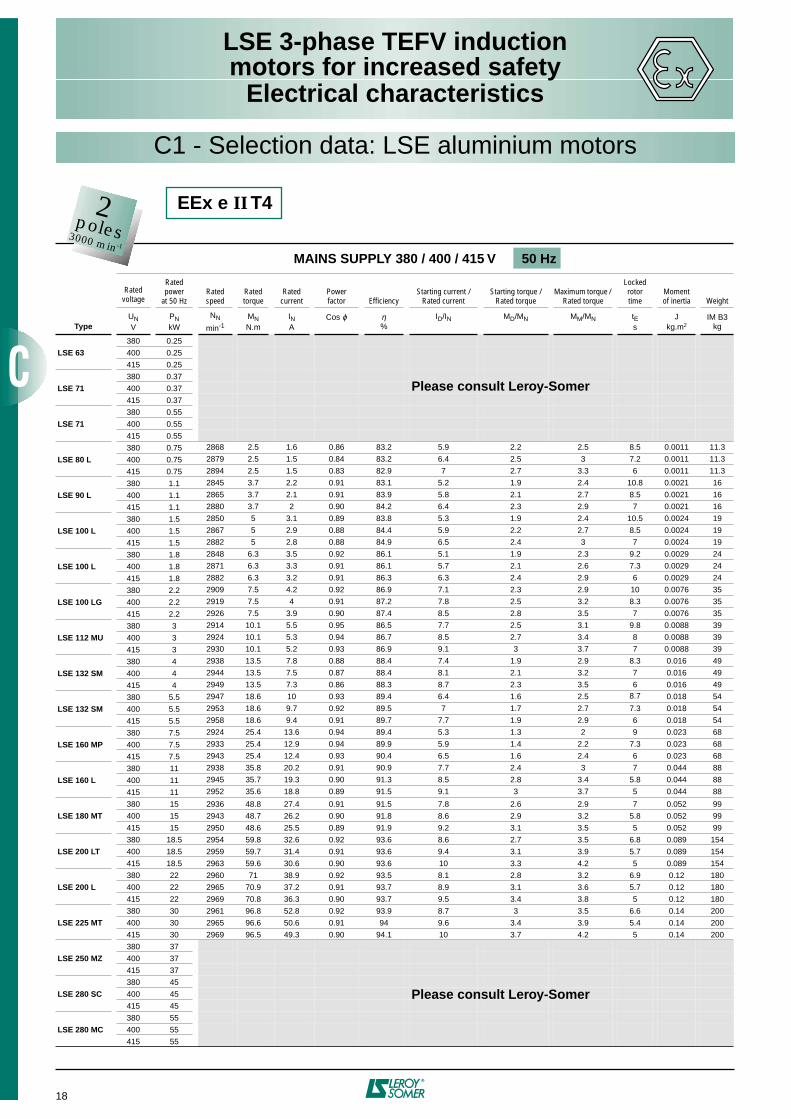
C1 - Selection data: LSE aluminium motors
MAINS SUPPLY 380 / 400 / 415 V 50 Hz
Rated voltage
Rated power
at 50 HzRated speed
Ratedtorque
Rated current
Powerfactor Efficiency
Starting current / Rated current
Starting torque / Rated torque
Maximum torque / Rated torque
Lockedrotortime
Momentof inertia Weight
TypeUNV
PNkW
NN
min-1MNN.m
INA
Cos ϕ η%
ID/IN MD/MN MM/MN tEs
Jkg.m2
IM B3kg
380 0.25
LSE 63 400 0.25
415 0.25
380 0.37
LSE 71 400 0.37
415 0.37
380 0.55
LSE 71 400 0.55
415 0.55
380 0.75 2868 2.5 1.6 0.86 83.2 5.9 2.2 2.5 8.5 0.0011 11.3
LSE 80 L 400 0.75 2879 2.5 1.5 0.84 83.2 6.4 2.5 3 7.2 0.0011 11.3
415 0.75 2894 2.5 1.5 0.83 82.9 7 2.7 3.3 6 0.0011 11.3
380 1.1 2845 3.7 2.2 0.91 83.1 5.2 1.9 2.4 10.8 0.0021 16
LSE 90 L 400 1.1 2865 3.7 2.1 0.91 83.9 5.8 2.1 2.7 8.5 0.0021 16
415 1.1 2880 3.7 2 0.90 84.2 6.4 2.3 2.9 7 0.0021 16
380 1.5 2850 5 3.1 0.89 83.8 5.3 1.9 2.4 10.5 0.0024 19
LSE 100 L 400 1.5 2867 5 2.9 0.88 84.4 5.9 2.2 2.7 8.5 0.0024 19
415 1.5 2882 5 2.8 0.88 84.9 6.5 2.4 3 7 0.0024 19
380 1.8 2848 6.3 3.5 0.92 86.1 5.1 1.9 2.3 9.2 0.0029 24
LSE 100 L 400 1.8 2871 6.3 3.3 0.91 86.1 5.7 2.1 2.6 7.3 0.0029 24
415 1.8 2882 6.3 3.2 0.91 86.3 6.3 2.4 2.9 6 0.0029 24
380 2.2 2909 7.5 4.2 0.92 86.9 7.1 2.3 2.9 10 0.0076 35
LSE 100 LG 400 2.2 2919 7.5 4 0.91 87.2 7.8 2.5 3.2 8.3 0.0076 35
415 2.2 2926 7.5 3.9 0.90 87.4 8.5 2.8 3.5 7 0.0076 35
380 3 2914 10.1 5.5 0.95 86.5 7.7 2.5 3.1 9.8 0.0088 39
LSE 112 MU 400 3 2924 10.1 5.3 0.94 86.7 8.5 2.7 3.4 8 0.0088 39
415 3 2930 10.1 5.2 0.93 86.9 9.1 3 3.7 7 0.0088 39
380 4 2938 13.5 7.8 0.88 88.4 7.4 1.9 2.9 8.3 0.016 49
LSE 132 SM 400 4 2944 13.5 7.5 0.87 88.4 8.1 2.1 3.2 7 0.016 49
415 4 2949 13.5 7.3 0.86 88.3 8.7 2.3 3.5 6 0.016 49
380 5.5 2947 18.6 10 0.93 89.4 6.4 1.6 2.5 8.7 0.018 54
LSE 132 SM 400 5.5 2953 18.6 9.7 0.92 89.5 7 1.7 2.7 7.3 0.018 54
415 5.5 2958 18.6 9.4 0.91 89.7 7.7 1.9 2.9 6 0.018 54
380 7.5 2924 25.4 13.6 0.94 89.4 5.3 1.3 2 9 0.023 68
LSE 160 MP 400 7.5 2933 25.4 12.9 0.94 89.9 5.9 1.4 2.2 7.3 0.023 68
415 7.5 2943 25.4 12.4 0.93 90.4 6.5 1.6 2.4 6 0.023 68
380 11 2938 35.8 20.2 0.91 90.9 7.7 2.4 3 7 0.044 88
LSE 160 L 400 11 2945 35.7 19.3 0.90 91.3 8.5 2.8 3.4 5.8 0.044 88
415 11 2952 35.6 18.8 0.89 91.5 9.1 3 3.7 5 0.044 88
380 15 2936 48.8 27.4 0.91 91.5 7.8 2.6 2.9 7 0.052 99
LSE 180 MT 400 15 2943 48.7 26.2 0.90 91.8 8.6 2.9 3.2 5.8 0.052 99
415 15 2950 48.6 25.5 0.89 91.9 9.2 3.1 3.5 5 0.052 99
380 18.5 2954 59.8 32.6 0.92 93.6 8.6 2.7 3.5 6.8 0.089 154
LSE 200 LT 400 18.5 2959 59.7 31.4 0.91 93.6 9.4 3.1 3.9 5.7 0.089 154
415 18.5 2963 59.6 30.6 0.90 93.6 10 3.3 4.2 5 0.089 154
380 22 2960 71 38.9 0.92 93.5 8.1 2.8 3.2 6.9 0.12 180
LSE 200 L 400 22 2965 70.9 37.2 0.91 93.7 8.9 3.1 3.6 5.7 0.12 180
415 22 2969 70.8 36.3 0.90 93.7 9.5 3.4 3.8 5 0.12 180
380 30 2961 96.8 52.8 0.92 93.9 8.7 3 3.5 6.6 0.14 200
LSE 225 MT 400 30 2965 96.6 50.6 0.91 94 9.6 3.4 3.9 5.4 0.14 200
415 30 2969 96.5 49.3 0.90 94.1 10 3.7 4.2 5 0.14 200
380 37
LSE 250 MZ 400 37
415 37
380 45
LSE 280 SC 400 45
415 45
380 55
LSE 280 MC 400 55
415 55
EEx e II T42poles3000 min-1
Please consult Leroy-Somer
Please consult Leroy-Somer

LSE 3-phase TEFV inductionmotors for increased safety
Electrical characteristics
19
C1 - Selection data: LSE aluminium motors
MAINS SUPPLY 380 / 400 / 415 V 50 Hz
Ratedvoltage
Rated power
at 50 HzRated speed
Ratedtorque
Rated current
Powerfactor Efficiency
Starting current / Rated current
Starting torque / Rated torque
Maximum torque / Rated torque
Lockedrotortime
Momentof inertia Weight
TypeUNV
PNkW
NN
min-1MNN.m
INA
Cos ϕ η%
ID/IN MD/MN MM/MN tEs
Jkg.m2
IM B3kg
380 0.25
LSE 63 400 0.25
415 0.25
380 0.37
LSE 71 400 0.37
415 0.37
380 0.55 1410 3.75 1.4 0.78 74 4.9 1.7 1.7 7.3 0.0024 10.9
LSE 80 L 400 0.55 1425 3.75 1.4 0.76 75 5.1 1.9 2 6.7 0.0024 10.9
415 0.55 1430 3.75 1.4 0.73 75 5.4 2.1 2.3 6 0.0024 10.9
380 0.75 1445 5 1.8 0.79 81 5.2 1.7 2.1 8 0.0032 13.5
LSE 90 S 400 0.75 1451 5 1.7 0.77 81.4 5.6 1.9 2.4 6.9 0.0032 13.5
415 0.75 1455 5 1.7 0.74 81.4 6 2.1 2.6 6 0.0032 13.5
380 1.1 1440 7.5 2.6 0.80 81.7 5 1.7 2.1 8.3 0.0037 15.2
LSE 90 L 400 1.1 1447 7.5 2.5 0.78 82.1 5.5 1.8 2.3 6.9 0.0037 15.2
415 1.1 1452 7.5 2.5 0.76 82.2 5.9 2 2.5 6 0.0037 15.2
380 1.5 1434 10 3.4 0.82 82.2 4.9 1.7 2 8.4 0.0064 25.5
LSE 100 L 400 1.5 1442 10 3.3 0.80 82.8 5.4 1.8 2.2 6.9 0.0064 25.5
415 1.5 1448 10 3.2 0.78 83.1 5.8 2 2.4 6 0.0064 25.5
380 1.8 1429 12 4 0.83 82.3 4.6 1.6 1.9 8.9 0.0073 27.5
LSE 100 L 400 1.8 1437 12 3.9 0.81 83 5.1 1.7 2.1 7.2 0.0073 27.5
415 1.8 1444 12 3.8 0.79 83.4 5.6 1.9 2.3 6 0.0073 27.5
380 2.2 1461 15 4.5 0.85 86.9 6 1.7 2 8.6 0.0109 30.5
LSE 100 LG 400 2.2 1466 15 4.4 0.84 87.3 6.6 1.8 2.2 7.1 0.0109 30.5
415 2.2 1469 15 4.3 0.82 87.4 7.2 2 2.4 6 0.0109 30.5
380 3 1459 20 6.1 0.86 87.4 6.1 1.8 2 8.6 0.014 36.5
LSE 112 MU 400 3 1464 20 5.9 0.85 87.8 6.7 2 2.2 7.1 0.014 36.5
415 3 1467 20 5.7 0.83 87.9 7.3 2.1 2.4 6 0.014 36.5
380 4 1460 27.5 7.6 0.91 88 8 1.7 2.3 9.5 0.019 54.7
LSE 132 SM 400 4 1465 27.5 7.4 0.89 88 8.6 1.8 2.6 8.2 0.019 54.7
415 4 1470 27.5 7.2 0.88 88 9.3 2 2.8 7 0.019 54.7
380 5.5 1462 37.5 10.7 0.88 89 6.7 1.8 2.4 8.2 0.023 59.9
LSE 132 SM 400 5.5 1466 37.5 10.4 0.87 89.1 7.3 2 2.7 6.9 0.023 59.9
415 5.5 1469 37.5 10.2 0.85 89 7.8 2.2 2.9 6 0.023 59.9
380 7.5 1456 50 14.4 0.89 88.8 5.7 1.5 2.1 8.8 0.0306 65.5
LSE 132 MU 400 7.5 1461 50 13.8 0.88 89.2 6.3 1.6 2.3 7.2 0.0306 65.5
415 7.5 1465 50 13.4 0.87 89.3 6.9 1.8 2.5 6 0.0306 65.5
380 11 1462 71.9 21.3 0.87 90.1 6.9 2.4 2.9 9.9 0.085 100
LSE 160 L 400 11 1467 71.6 20.4 0.86 90.5 7.6 2.7 3.2 8.2 0.085 100
415 11 1470 71.5 19.9 0.85 90.7 8.2 3 3.7 7 0.085 100
380 15 1477 97.0 29.7 0.83 92.3 8.8 4 4 12.9 0.151 165
LSE 180 LU 400 15 1480 96.8 29 0.81 92.3 9.5 4.4 4.4 11 0.151 165
415 15 1482 96.7 29 0.78 92.3 10 4.8 4.8 10 0.151 165
380 18.5 1470 120 35.4 0.86 92.2 7.6 3.2 3.2 6.4 0.151 165
LSE 180 LU 400 18.5 1473 120 34.4 0.84 92.3 8.2 3.6 3.6 5.5 0.151 165
415 18.5 1475 120 34 0.82 92.4 8.6 3.9 3.8 5 0.151 165
380 22 1480 142 43 0.83 93.5 8 3.4 3.3 11.4 0.240 205
LSE 200 L 400 22 1482 142 41.9 0.81 93.6 8.7 3.7 3.6 9.6 0.240 205
415 22 1484 142 41.4 0.79 93.5 9 4.1 3.9 9 0.240 205
380 30 1477 194 58.7 0.83 93.6 7.3 3.3 3.2 9.3 0.290 235
LSE 225 SR 400 30 1479 194 57.1 0.81 93.6 7.9 3.7 3.6 7.9 0.290 235
415 30 1481 194 56.4 0.79 93.6 8.4 4.1 3.9 7 0.290 235
380 37
LSE 250 ME 400 37
415 37
380 45
LSE 280 SC 400 45
415 45
380 55
LSE 280 MC 400 55
415 55
EEx e II T44poles1500 min-1
Please consult Leroy-Somer
Please consult Leroy-Somer
LSE 3-phase TEFV inductionmotors for increased safety
Electrical characteristics
20
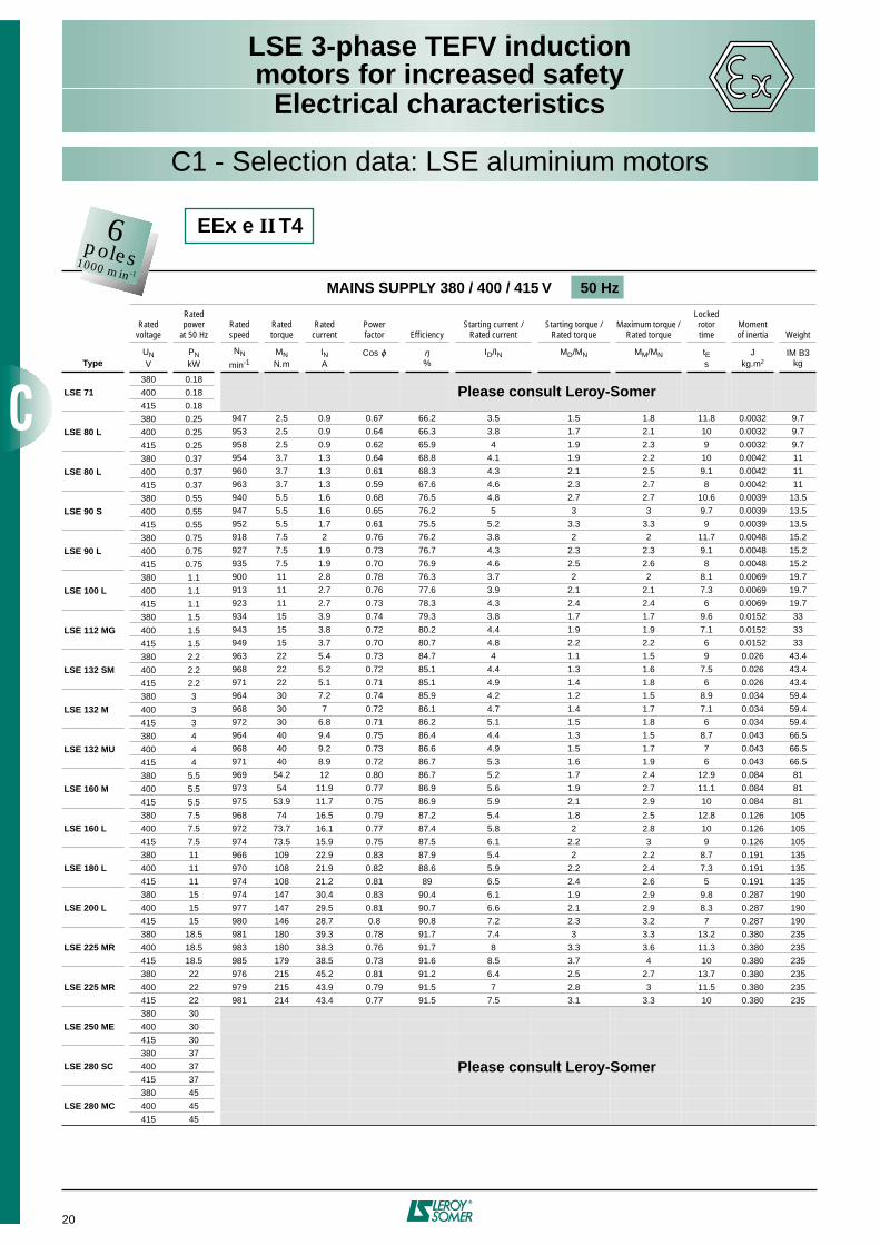
C1 - Selection data: LSE aluminium motors
MAINS SUPPLY 380 / 400 / 415 V 50 Hz
Ratedvoltage
Rated power
at 50 HzRated speed
Ratedtorque
Rated current
Powerfactor Efficiency
Starting current / Rated current
Starting torque / Rated torque
Maximum torque / Rated torque
Lockedrotortime
Momentof inertia Weight
TypeUNV
PNkW
NN
min-1MNN.m
INA
Cos ϕ η%
ID/IN MD/MN MM/MN tEs
Jkg.m2
IM B3kg
380 0.18
LSE 71 400 0.18
415 0.18
380 0.25 947 2.5 0.9 0.67 66.2 3.5 1.5 1.8 11.8 0.0032 9.7
LSE 80 L 400 0.25 953 2.5 0.9 0.64 66.3 3.8 1.7 2.1 10 0.0032 9.7
415 0.25 958 2.5 0.9 0.62 65.9 4 1.9 2.3 9 0.0032 9.7
380 0.37 954 3.7 1.3 0.64 68.8 4.1 1.9 2.2 10 0.0042 11
LSE 80 L 400 0.37 960 3.7 1.3 0.61 68.3 4.3 2.1 2.5 9.1 0.0042 11
415 0.37 963 3.7 1.3 0.59 67.6 4.6 2.3 2.7 8 0.0042 11
380 0.55 940 5.5 1.6 0.68 76.5 4.8 2.7 2.7 10.6 0.0039 13.5
LSE 90 S 400 0.55 947 5.5 1.6 0.65 76.2 5 3 3 9.7 0.0039 13.5
415 0.55 952 5.5 1.7 0.61 75.5 5.2 3.3 3.3 9 0.0039 13.5
380 0.75 918 7.5 2 0.76 76.2 3.8 2 2 11.7 0.0048 15.2
LSE 90 L 400 0.75 927 7.5 1.9 0.73 76.7 4.3 2.3 2.3 9.1 0.0048 15.2
415 0.75 935 7.5 1.9 0.70 76.9 4.6 2.5 2.6 8 0.0048 15.2
380 1.1 900 11 2.8 0.78 76.3 3.7 2 2 8.1 0.0069 19.7
LSE 100 L 400 1.1 913 11 2.7 0.76 77.6 3.9 2.1 2.1 7.3 0.0069 19.7
415 1.1 923 11 2.7 0.73 78.3 4.3 2.4 2.4 6 0.0069 19.7
380 1.5 934 15 3.9 0.74 79.3 3.8 1.7 1.7 9.6 0.0152 33
LSE 112 MG 400 1.5 943 15 3.8 0.72 80.2 4.4 1.9 1.9 7.1 0.0152 33
415 1.5 949 15 3.7 0.70 80.7 4.8 2.2 2.2 6 0.0152 33
380 2.2 963 22 5.4 0.73 84.7 4 1.1 1.5 9 0.026 43.4
LSE 132 SM 400 2.2 968 22 5.2 0.72 85.1 4.4 1.3 1.6 7.5 0.026 43.4
415 2.2 971 22 5.1 0.71 85.1 4.9 1.4 1.8 6 0.026 43.4
380 3 964 30 7.2 0.74 85.9 4.2 1.2 1.5 8.9 0.034 59.4
LSE 132 M 400 3 968 30 7 0.72 86.1 4.7 1.4 1.7 7.1 0.034 59.4
415 3 972 30 6.8 0.71 86.2 5.1 1.5 1.8 6 0.034 59.4
380 4 964 40 9.4 0.75 86.4 4.4 1.3 1.5 8.7 0.043 66.5
LSE 132 MU 400 4 968 40 9.2 0.73 86.6 4.9 1.5 1.7 7 0.043 66.5
415 4 971 40 8.9 0.72 86.7 5.3 1.6 1.9 6 0.043 66.5
380 5.5 969 54.2 12 0.80 86.7 5.2 1.7 2.4 12.9 0.084 81
LSE 160 M 400 5.5 973 54 11.9 0.77 86.9 5.6 1.9 2.7 11.1 0.084 81
415 5.5 975 53.9 11.7 0.75 86.9 5.9 2.1 2.9 10 0.084 81
380 7.5 968 74 16.5 0.79 87.2 5.4 1.8 2.5 12.8 0.126 105
LSE 160 L 400 7.5 972 73.7 16.1 0.77 87.4 5.8 2 2.8 10 0.126 105
415 7.5 974 73.5 15.9 0.75 87.5 6.1 2.2 3 9 0.126 105
380 11 966 109 22.9 0.83 87.9 5.4 2 2.2 8.7 0.191 135
LSE 180 L 400 11 970 108 21.9 0.82 88.6 5.9 2.2 2.4 7.3 0.191 135
415 11 974 108 21.2 0.81 89 6.5 2.4 2.6 5 0.191 135
380 15 974 147 30.4 0.83 90.4 6.1 1.9 2.9 9.8 0.287 190
LSE 200 L 400 15 977 147 29.5 0.81 90.7 6.6 2.1 2.9 8.3 0.287 190
415 15 980 146 28.7 0.8 90.8 7.2 2.3 3.2 7 0.287 190
380 18.5 981 180 39.3 0.78 91.7 7.4 3 3.3 13.2 0.380 235
LSE 225 MR 400 18.5 983 180 38.3 0.76 91.7 8 3.3 3.6 11.3 0.380 235
415 18.5 985 179 38.5 0.73 91.6 8.5 3.7 4 10 0.380 235
380 22 976 215 45.2 0.81 91.2 6.4 2.5 2.7 13.7 0.380 235
LSE 225 MR 400 22 979 215 43.9 0.79 91.5 7 2.8 3 11.5 0.380 235
415 22 981 214 43.4 0.77 91.5 7.5 3.1 3.3 10 0.380 235
380 30
LSE 250 ME 400 30
415 30
380 37
LSE 280 SC 400 37
415 37
380 45
LSE 280 MC 400 45
415 45
EEx e II T46poles1000 min-1
Please consult Leroy-Somer
Please consult Leroy-Somer

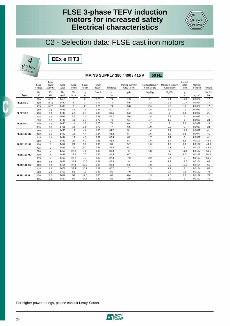
FLSE 3-phase TEFV inductionmotors for increased safety
Electrical characteristics
21
PAGES
2 poles - 3000 min–1 - EEx e II T3 ....................................................... 22
2 poles - 3000 min–1 - EEx e II T3 VIK* .............................................. 23
4 poles - 1500 min–1 - EEx e II T3 ....................................................... 24
4 poles - 1500 min–1 - EEx e II T3 VIK* .............................................. 25
6 poles - 1000 min–1 - EEx e II T3 ....................................................... 26
6 poles - 1000 min–1 - EEx e II T3 VIK* .............................................. 27
2 poles - 3000 min–1 - EEx e II T4 ....................................................... 28
4 poles - 1500 min–1 - EEx e II T4 ....................................................... 29
6 poles - 1000 min–1 - EEx e II T4 ....................................................... 30
* VIK: extension of EN 50019 requirements to particular specifications intendedfor German manufacturing companies:
- ranges with special power ratings according to frame size (DIN 42673)- increased duration tE (≥ 7 sec)
- 2nd nameplate in the terminal box- ISO M25 cable gland from frame size 80 mm upwards- oil-resistant seals- terminal blocks not split from frame size 160 mm upwards
Other polarities (1 or 2-speed): please consult Leroy-Somer.
C2 - Selection data: FLSE cast iron motors

FLSE 3-phase TEFV inductionmotors for increased safety
Electrical characteristics
22
C2 - Selection data: FLSE cast iron motors
For higher power ratings, please consult Leroy-Somer.
MAINS SUPPLY 380 / 400 / 415 V 50 Hz
Ratedvoltage
Rated power
at 50 HzRated speed
Ratedtorque
Rated current
Powerfactor Efficiency
Starting current / Rated current
Starting torque / Rated torque
Maximum torque / Rated torque
Lockedrotortime
Momentof inertia Weight
TypeUNV
PNkW
NN
min-1MNN.m
INA
Cos ϕ η%
ID/IN MD/MN MM/MN tEs
Jkg.m2
IM B3kg
380 0.75 2860 2.5 1.7 0.86 79.2 6.8 2.7 2.8 8.3 0.0007 15
FLSE 80 L 400 0.75 2872 2.5 1.6 0.84 79.4 7.1 2.9 3 7.6 0.0007 15
415 0.75 2890 2.5 1.6 0.81 79.5 7.4 3.1 3.2 7 0.0007 15
380 1.1 2860 3.75 2.4 0.89 78 7.1 2.9 2.8 12.6 0.0009 18
FLSE 80 L 400 1.1 2870 3.75 2.3 0.86 78.5 7.5 3.2 3.1 11.1 0.0009 18
415 1.1 2885 3.75 2.3 0.84 78.7 7.9 3.4 3.3 10 0.0009 18
380 1.5 2845 5 3.1 0.90 82.3 7 2.8 2.8 11.6 0.00175 23.5
FLSE 90 S 400 1.5 2860 5 2.9 0.88 83.6 7.5 3.1 3.1 10.2 0.00175 23.5
415 1.5 2880 5 2.9 0.87 83.5 8.2 3.5 3.5 8.5 0.00175 23.5
380 2.2 2869 7.5 4.4 0.89 85.5 6.2 2.1 2.7 11 0.0023 27.7
FLSE 90 L 400 2.2 2884 7.5 4.2 0.87 85.7 6.7 2.4 3.1 9.4 0.0023 27.7
415 2.2 2895 7.5 4.1 0.87 85.8 7.5 2.6 3.3 7.5 0.0023 27.7
380 3 2887 10.1 5.8 0.92 85.7 5.5 1.6 2.3 13.3 0.0069 42
FLSE 100 LK 400 3 2900 10.1 5.5 0.91 86.2 6.1 1.8 2.5 10.8 0.0069 42
415 3 2910 10.1 5.3 0.91 86.4 6.7 2 2.8 9 0.0069 42
380 4 2920 13.5 7.4 0.92 88.5 6.9 1.8 2.7 9.9 0.0099 54
FLSE 112 MU 400 4 2928 13.5 7.1 0.92 88.6 7.5 2 3 8.4 0.0099 54
415 4 2935 13.5 6.9 0.91 88.6 8.2 2.2 3.2 7 0.0099 54
380 5.5 2916 18.6 10.2 0.92 89.4 5.9 1.5 2.4 10.4 0.0263 71
FLSE 132 SM 400 5.5 2926 18.6 9.7 0.91 89.8 6.5 1.7 2.6 8.6 0.0263 71
415 5.5 2933 18.6 9.4 0.90 89.9 7.2 1.8 2.8 7 0.0263 71
380 7.5 2921 25.4 13.6 0.92 90.2 6.3 1.6 2.4 10.2 0.031 75
FLSE 132 SM 400 7.5 2929 25.4 13.1 0.92 90.4 6.9 1.7 2.6 8.5 0.031 75
415 7.5 2936 25.4 12.6 0.91 90.6 7.6 1.9 2.9 7 0.031 75
EEx e II T32poles3000 min-1

FLSE 3-phase TEFV inductionmotors for increased safety
Electrical characteristics
23
C2 - Selection data: FLSE cast iron motors
For higher power ratings, please consult Leroy-Somer.
MAINS SUPPLY 380 / 400 / 420 V 50 Hz
Ratedvoltage
Rated power
at 50 HzRated speed
Ratedtorque
Rated current
Powerfactor Efficiency
Starting current / Rated current
Starting torque / Rated torque
Maximum torque / Rated torque
Lockedrotortime
Momentof inertia Weight
TypeUNV
PNkW
NN
min-1MNN.m
INA
Cos ϕ η%
ID/IN MD/MN MM/MN tEs
Jkg.m2
IM B3kg
380 1.1 2860 3.75 2.4 0.89 78 7.1 2.9 2.8 12.6 0.0009 19
FLSE 80 L 400 1.1 2875 3.75 2.4 0.85 78.2 7.5 3.2 3.1 11.4 0.0009 19
420 1.1 2890 3.75 2.3 0.83 78.4 8 3.7 3.6 10 0.0009 19
380 1.5 2845 5 3.1 0.90 82.3 7 2.8 2.8 12 0.00175 23.5
FLSE 90 S 400 1.5 2865 5 3 0.87 82.8 7.5 3.1 3.1 10.4 0.00175 23.5
420 1.5 2886 5 2.9 0.85 83.4 8.3 3.6 3.6 8.5 0.00175 23.5
380 1.85 2881 6.3 3.7 0.88 86.1 6.4 2.2 2.6 9.3 0.0023 27.7
FLSE 90 L 400 1.85 2890 6.3 3.6 0.86 86.2 6.5 2.4 3 9 0.0023 27.7
420 1.85 2903 6.3 3.5 0.85 86.2 6.7 2.7 3.5 8.5 0.0023 27.7
380 2.5 2896 8.5 4.8 0.91 86.1 5.8 1.7 2.4 11.1 0.0069 42
FLSE 100 LK 400 2.5 2905 8.5 4.6 0.90 86.5 6.2 1.9 2.7 9.7 0.0069 42
420 2.5 2920 8.5 4.4 0.90 86.7 7.3 2.1 3 7 0.0069 42
380 3.3 2915 11.2 6.5 0.95 82.1 8.9 2.9 3.8 11.4 0.0084 48
FLSE 112 M 400 3.3 2925 11.2 6.2 0.93 82.5 9.3 3.2 4.1 10.4 0.0084 48
420 3.3 2935 11.2 6 0.91 82.7 10 3.5 4.6 9 0.0084 48
380 4.6 2925 15.6 8.5 0.91 89.8 6.2 1.6 2.4 11.7 0.0263 71
FLSE 132 SM 400 4.6 2932 15.6 8.2 0.90 90 6.8 1.7 2.6 9.7 0.0263 71
420 4.6 2939 15.6 7.9 0.90 90.2 7.5 1.9 2.9 8 0.0263 71
380 5.5 2929 18.6 10.1 0.91 90.2 6.35 1.5 2.4 13 0.031 75
FLSE 132 SM 400 5.5 2940 18.6 9.9 0.89 90 7.2 1.9 3 10.1 0.031 75
420 5.5 2957 18.6 9.7 0.87 89.8 8.1 2.4 3.7 8 0.031 75
2poles3000 min-1
EEx e II T3 VIK
FLSE 3-phase TEFV inductionmotors for increased safety
Electrical characteristics
24
C2 - Selection data: FLSE cast iron motors
EEx e II T3
For higher power ratings, please consult Leroy-Somer.
MAINS SUPPLY 380 / 400 / 415 V 50 Hz
Ratedvoltage
Rated power
at 50 HzRated speed
Ratedtorque
Rated current
Powerfactor Efficiency
Starting current / Rated current
Starting torque / Rated torque
Maximum torque / Rated torque
Lockedrotortime
Momentof inertia Weight
TypeUNV
PNkW
NN
min-1MNN.m
INA
Cos ϕ η%
ID/IN MD/MN MM/MN tEs
Jkg.m2
IM B3kg
380 0.75 1415 5 2 0.76 74 5.32 2 2.1 11.9 0.0024 17
FLSE 80 L 400 0.75 1430 5 2 0.72 74 5.6 2.2 2.3 10.7 0.0024 17
415 0.75 1430 5 2 0.70 74 5.8 2.4 2.6 10 0.0024 17
380 1.1 1435 7.5 2.5 0.84 80.7 4.7 1.5 1.8 10 0.0032 21
FLSE 90 S 400 1.1 1443 7.5 2.4 0.83 81.5 5.2 1.6 2 8.1 0.0032 21
415 1.1 1449 7.5 2.3 0.81 81.7 5.6 1.8 2.2 7 0.0032 21
380 1.5 1445 10 3.7 0.79 78 6.1 1.7 1.9 8 0.0037 23
FLSE 90 L 400 1.5 1450 10 3.7 0.75 78 6.4 1.7 2 7.2 0.0037 23
415 1.5 1455 10 3.8 0.72 77 6.5 1.9 2.2 7 0.0037 23
380 2.2 1455 15 4.6 0.85 84.7 5.1 1.4 1.7 11.8 0.0077 41
FLSE 100 LK 400 2.2 1460 15 4.4 0.84 85.2 5.7 1.5 1.9 9.5 0.0077 41
415 2.2 1464 15 4.3 0.82 85.4 6.2 1.7 2.1 8 0.0077 41
380 3 1452 20 6.2 0.86 85.4 5.1 1.5 1.7 8.6 0.0107 43.6
FLSE 100 LK 400 3 1457 20 5.9 0.85 86 5.7 1.6 1.9 6.9 0.0107 43.6
415 3 1462 20 5.7 0.84 86.5 6.1 1.7 2.1 6 0.0107 43.6
380 4 1453 27.2 7.9 0.88 86.9 6 1.8 2 11.8 0.0137 51.5
FLSE 112 MU 400 4 1458 27.2 7.7 0.86 86.9 6.7 2 2.1 9.5 0.0137 51.5
415 4 1466 27.2 7.7 0.82 87.4 7.3 2.2 2.4 8 0.0137 51.5
380 5.5 1451 37.4 10.5 0.91 87.9 6 1.6 2.2 12.2 0.0154 65
FLSE 132 SM 400 5.5 1464 37.4 10.3 0.87 88.4 6.5 1.8 2.5 10.5 0.0154 65
415 5.5 1471 37.4 10.7 0.81 87.7 7 1.9 2.7 9 0.0154 65
380 7.5 1455 50 15 0.88 86 7.9 1.7 2.4 7.6 0.0192 70
FLSE 132 M 400 7.5 1457 50 14.8 0.85 86 8.4 1.9 2.6 6.7 0.0192 70
415 7.5 1460 50 14.6 0.83 86 8.9 2.1 2.8 6 0.0192 70
4poles1500 min-1

FLSE 3-phase TEFV inductionmotors for increased safety
Electrical characteristics
25
For higher power ratings, please consult Leroy-Somer.
MAINS SUPPLY 380 / 400 / 420 V 50 Hz
Ratedvoltage
Rated power
at 50 HzRated speed
Ratedtorque
Rated current
Powerfactor Efficiency
Starting current / Rated current
Starting torque / Rated torque
Maximum torque / Rated torque
Lockedrotortime
Momentof inertia Weight
TypeUNV
PNkW
NN
min-1MNN.m
INA
Cos ϕ η%
ID/IN MD/MN MM/MN tEs
Jkg.m2
IM B3kg
380 1 1444 6.8 2.3 0.83 81.6 5.2 1.7 2 11.7 0.0032 21
FLSE 90 S 400 1 1450 6.8 2.2 0.81 81.8 5.9 1.9 2.3 9.1 0.0032 21
420 1 1456 6.8 2.2 0.78 81.9 6.3 2.1 2.5 8 0.0032 21
380 1.35 1444 9.2 3 0.83 83.5 6.3 1.9 2.2 10.5 0.0037 23
FLSE 90 L 400 1.35 1450 9.2 2.9 0.81 83.5 6.5 2.2 2.4 9.9 0.0037 23
420 1.35 1456 9.2 2.9 0.78 83.5 6.8 2.4 2.7 9 0.0037 23
380 1.85 1460 12.6 3.9 0.84 85.3 5.6 1.5 1.9 8.8 0.0077 41
FLSE 100 LK 400 1.85 1465 12.6 3.8 0.83 85.5 6.1 1.7 2.1 7.5 0.0077 41
420 1.85 1470 12.6 3.7 0.81 85.8 6.8 1.8 2.3 6 0.0077 41
380 2.5 1464 16.9 5.2 0.84 86.7 6.3 1.7 2.1 11.9 0.0107 43.6
FLSE 100 LK 400 2.5 1467 16.9 5.1 0.82 86.8 7 1.9 2.4 9.7 0.0107 43.6
420 2.5 1471 16.9 4.9 0.80 86.8 7.7 2.2 2.6 8 0.0107 43.6
380 3.6 1450 24.4 7.3 0.87 86.3 6.6 1.9 2.7 13.6 0.0137 51.5
FLSE 112 MU 400 3.6 1455 24.4 7.1 0.85 86.4 7.1 2 2.8 11.8 0.0137 51.5
420 3.6 1460 24.4 7 0.82 86.5 7.7 2.1 3 10 0.0137 51.5
380 5 1450 33.9 10 0.89 85.4 8 2.3 2.8 13.2 0.0154 65
FLSE 132 SM 400 5 1457 33.9 9.7 0.87 85.5 8.6 2.5 3.1 11.4 0.0154 65
420 5 1462 33.9 9.4 0.85 85.6 9.2 2.8 3.4 10 0.0154 65
380 6.8 1445 46.2 13.5 0.90 84.8 7.3 2.8 2.6 12.2 0.0192 70
FLSE 132 M 400 6.8 1455 46.2 13.1 0.88 84.9 7.8 3.1 2.8 10.7 0.0192 70
420 6.8 1460 46.2 12.6 0.87 85 8.5 3.4 3 9 0.0192 70
C2 - Selection data: FLSE cast iron motors
4poles1500 min-1
EEx e II T3 VIK
FLSE 3-phase TEFV inductionmotors for increased safety
Electrical characteristics
26
EEx e II T3
For higher power ratings, please consult Leroy-Somer.
MAINS SUPPLY 380 / 400 / 415 V 50 Hz
Ratedvoltage
Rated power
at 50 HzRated speed
Ratedtorque
Rated current
Powerfactor Efficiency
Starting current / Rated current
Starting torque / Rated torque
Maximum torque / Rated torque
Lockedrotor time
Momentof inertia Weight
TypeUNV
PNkW
NN
min-1MNN.m
INA
Cos ϕ η%
ID/IN MD/MN MM/MN tEs
Jkg.m2
IM B3kg
380 0.37 941 3.7 1.2 0.70 65.2 3.3 1.4 1.7 14 0.0032 15
FLSE 80 L 400 0.37 948 3.7 1.2 0.68 65.3 3.7 1.6 2 11.1 0.0032 15
415 0.37 955 3.7 1.2 0.65 65.1 3.9 1.8 2.2 10 0.0032 15
380 0.55 950 5.5 1.8 0.68 69.9 4.1 1.9 2.2 10 0.0042 16
FLSE 80 L 400 0.55 955 5.5 1.8 0.64 68.6 4.5 2.1 2.4 8.4 0.0042 16
415 0.55 959 5.5 1.9 0.60 66.3 4.6 2.4 2.7 8 0.0042 16
380 0.75 928 7.5 2.1 0.71 75.4 4.3 2.4 2.4 11.9 0.0039 19
FLSE 90 S 400 0.75 935 7.5 2.2 0.67 75 4.6 2.6 2.6 10.5 0.0039 19
415 0.75 942 7.5 2.2 0.63 74.3 4.7 2.9 2.9 10 0.0039 19
380 1.1 907 11 3 0.76 74.7 3.9 2.1 2.1 11.5 0.0048 21
FLSE 90 L 400 1.1 918 11 3 0.72 75.2 4.1 2.2 2.2 10.4 0.0048 21
415 1.1 926 11 3 0.68 74.8 4.4 2.5 2.5 9 0.0048 21
380 1.5 939 15 3.9 0.73 79.7 4.3 2 2 8.8 0.0136 41
FLSE 100 LK 400 1.5 947 15 3.8 0.71 80.4 4.8 2.2 2.2 7 0.0136 41
415 1.5 953 15 3.7 0.69 80.7 5.2 2.4 2.4 6 0.0136 41
380 2.2 928 22 5.6 0.75 78.8 4.2 1.9 1.8 8 0.0152 45
FLSE 112 M 400 2.2 938 22 5.4 0.74 80.1 4.3 2 2 7.5 0.0152 45
415 2.2 945 22 5.3 0.72 80.6 4.8 2.2 2.2 6 0.0152 45
380 3 958 30 7.2 0.75 84.2 3.8 1.1 1.5 8.8 0.026 72
FLSE 132 SM 400 3 963 30 7 0.74 84.6 4.3 1.2 1.6 7 0.026 72
415 3 967 30 6.9 0.72 84.7 4.6 1.3 1.7 6 0.026 72
380 4 962 40 9.5 0.75 85.5 4.2 1.2 1.5 8.5 0.034 76
FLSE 132 M 400 4 966 40 9.1 0.74 85.9 4.6 1.3 1.6 7.1 0.034 76
415 4 970 40 9 0.72 85.8 5 1.5 1.8 6 0.034 76
380 5.5 958 55 12.8 0.76 86 4.2 1.3 1.5 8.9 0.043 88
FLSE 132 MU 400 5.5 963 55 12.3 0.75 86.4 4.7 1.4 1.6 7.1 0.043 88
415 5.5 968 55 12 0.73 86.5 5.1 1.6 1.8 6 0.043 88
6poles1000 min-1
C2 - Selection data: FLSE cast iron motors

FLSE 3-phase TEFV inductionmotors for increased safety
Electrical characteristics
27
For higher power ratings, please consult Leroy-Somer.
MAINS SUPPLY 380 / 400 / 420 V 50 Hz
Ratedvoltage
Rated power
at 50 HzRated speed
Ratedtorque
Rated current
Powerfactor Efficiency
Starting current / Rated current
Starting torque / Rated torque
Maximum torque / Rated torque
Lockedrotortime
Momentof inertia Weight
TypeUNV
PNkW
NN
min-1MNN.m
INA
Cos ϕ η%
ID/IN MD/MN MM/MN tEs
Jkg.m2
IM B3kg
380 0.65 931 6.5 1.8 0.72 75.6 4.6 2.3 2.4 10.2 0.0039 19
FLSE 90 S 400 0.65 938 6.5 1.8 0.68 75.1 4.8 2.6 2.7 9.4 0.0039 19
420 0.65 945 6.5 1.9 0.63 74.6 4.9 2.9 3 9 0.0039 19
380 0.95 909 9.5 2.5 0.77 75.1 4 2.2 2.2 10.9 0.0048 21
FLSE 90 L 400 0.95 917 9.5 2.5 0.73 75.4 4.2 2.3 2.3 9.9 0.0048 21
420 0.95 931 9.5 2.5 0.69 75.8 4.4 2.5 2.5 9 0.0048 21
380 1.3 941 13 3.4 0.72 79.3 4.3 1.9 1.9 10.2 0.0136 41
FLSE 100 LK 400 1.3 948 13 3.3 0.71 79.8 4.7 2.2 2.2 8.6 0.0136 41
420 1.3 956 13 3.3 0.68 80.4 5.2 2.5 2.5 7 0.0136 41
380 1.9 929 19 4.9 0.75 78.7 3.8 1.6 1.6 11.6 0.0152 45
FLSE 112 M 400 1.9 940 19 4.7 0.73 79.7 4.2 1.9 1.9 9.5 0.0152 45
420 1.9 948 19 4.5 0.71 80.7 4.9 2.2 2.2 7 0.0152 45
380 2.6 959 26 6.2 0.75 84.5 3.7 1.1 1.4 11.3 0.026 72
FLSE 132 SM 400 2.6 964 26 6 0.74 84.7 4.2 1.2 1.6 8.8 0.026 72
420 2.6 969 26 5.8 0.72 85.1 4.7 1.3 1.7 7 0.026 72
380 3.5 962 35 8.3 0.75 85.3 4.1 1.2 1.5 10.4 0.034 76
FLSE 132 M 400 3.5 967 35 8 0.74 85.5 4.5 1.3 1.7 8.6 0.034 76
420 3.5 971 35 7.8 0.72 85.8 5 1.4 1.8 7 0.034 76
380 4.8 963 48 11.2 0.75 86.6 4.5 1.4 1.6 12 0.043 88
FLSE 132 MU 400 4.8 967 48 10.8 0.74 86.8 5 1.5 1.7 9.7 0.043 88
420 4.8 971 48 10.6 0.72 86.8 5.5 1.7 2 8 0.043 88
EEx e II T3 VIK
C2 - Selection data: FLSE cast iron motors
6poles1000 min-1

FLSE 3-phase TEFV inductionmotors for increased safety
Electrical characteristics
28
C2 - Selection data: FLSE cast iron motors
For higher power ratings, please consult Leroy-Somer.
MAINS SUPPLY 380 / 400 / 415 V 50 Hz
Ratedvoltage
Rated power
at 50 HzRated speed
Ratedtorque
Rated current
Powerfactor Efficiency
Starting current / Rated current
Starting torque / Rated torque
Maximum torque / Rated torque
Lockedrotortime
Momentof inertia Weight
TypeUNV
PNkW
NN
min-1MNN.m
INA
Cos ϕ η%
ID/IN MD/MN MM/MN tEs
Jkg.m2
IM B3kg
380 0.75 2868 2.5 1.6 0.86 83.2 5.9 2.2 2.5 8.5 0.0009 18
FLSE 80 L 400 0.75 2879 2.5 1.5 0.84 83.2 6.4 2.5 3 7.2 0.0009 18
415 0.75 2894 2.5 1.5 0.83 82.9 7 2.7 3.3 6 0.0009 18
380 1.1 2845 3.7 2.2 0.91 83.1 5.2 1.9 2.4 9.1 0.0021 25.5
FLSE 90 L 400 1.1 2865 3.7 2.1 0.91 83.9 5.8 2.1 2.7 7.3 0.0021 25.5
415 1.1 2880 3.7 2 0.90 84.2 6.4 2.3 2.9 6 0.0021 25.5
380 1.5 2850 5 3.1 0.89 83.8 5.3 1.9 2.4 9 0.0024 28.3
FLSE 90 LU 400 1.5 2867 5 2.9 0.88 84.4 5.9 2.2 2.7 7.3 0.0024 28.3
415 1.5 2882 5 2.8 0.88 84.9 6.5 2.4 3 6 0.0024 28.3
380 2.2 2909 7.5 4.2 0.92 86.9 7.1 2.3 2.9 8.6 0.0069 42
FLSE 100 LK 400 2.2 2919 7.5 4 0.91 87.2 7.8 2.5 3.2 7.1 0.0069 42
415 2.2 2926 7.5 3.9 0.90 87.4 8.5 2.8 3.5 6 0.0069 42
380 3 2914 10.1 5.5 0.95 86.5 7.7 2.5 3.1 8.4 0.0099 54
FLSE 112 MU 400 3 2924 10.1 5.3 0.94 86.7 8.5 2.7 3.4 6.9 0.0099 54
415 3 2930 10.1 5.2 0.93 86.9 9.1 3 3.7 6 0.0099 54
380 4 2938 13.5 7.8 0.88 88.4 7.4 1.9 2.9 8.3 0.0263 71
FLSE 132 SM 400 4 2944 13.5 7.5 0.87 88.4 8.1 2.1 3.2 7 0.0263 71
415 4 2949 13.5 7.3 0.86 88.3 8.7 2.3 3.5 6 0.0263 71
380 5.5 2947 18.6 10 0.93 89.4 6.4 1.6 2.5 8.7 0.031 75
FLSE 132 SM 400 5.5 2953 18.6 9.7 0.92 89.5 7 1.7 2.7 7.3 0.031 75
415 5.5 2958 18.6 9.4 0.91 89.7 7.7 1.9 2.9 6 0.031 75
380 7.5 2924 25.4 13.6 0.94 89.4 5.3 1.3 2 9 0.038 81
FLSE 132 MU 400 7.5 2933 25.4 12.9 0.94 89.9 5.9 1.4 2.2 7.3 0.038 81
415 7.5 2943 25.4 12.4 0.93 90.4 6.5 1.6 2.4 6 0.038 81
EEx e II T42poles3000 min-1
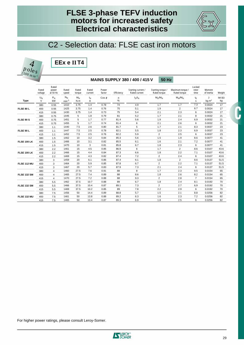
FLSE 3-phase TEFV inductionmotors for increased safety
Electrical characteristics
29
C2 - Selection data: FLSE cast iron motors
EEx e II T4
For higher power ratings, please consult Leroy-Somer.
MAINS SUPPLY 380 / 400 / 415 V 50 Hz
Ratedvoltage
Rated power
at 50 HzRated speed
Ratedtorque
Rated current
Powerfactor Efficiency
Starting current / Rated current
Starting torque / Rated torque
Maximum torque / Rated torque
Lockedrotortime
Momentof inertia Weight
TypeUNV
PNkW
NN
min-1MNN.m
INA
Cos ϕ η%
ID/IN MD/MN MM/MN tEs
Jkg.m2
IM B3kg
380 0.55 1410 3.75 1.4 0.78 74 4.9 1.7 1.7 7.3 0.0024 17
FLSE 80 L 400 0.55 1425 3.75 1.4 0.76 75 5.1 1.9 2 6.7 0.0024 17
415 0.55 1430 3.75 1.4 0.73 75 5.4 2.1 2.3 6 0.0024 17
380 0.75 1445 5 1.8 0.79 81 5.2 1.7 2.1 8 0.0032 21
FLSE 90 S 400 0.75 1451 5 1.7 0.77 81.4 5.6 1.9 2.4 6.9 0.0032 21
415 0.75 1455 5 1.7 0.74 81.4 6 2.1 2.6 6 0.0032 21
380 1.1 1440 7.5 2.6 0.80 81.7 5 1.7 2.1 8.3 0.0037 23
FLSE 90 L 400 1.1 1447 7.5 2.5 0.78 82.1 5.5 1.8 2.3 6.9 0.0037 23
415 1.1 1452 7.5 2.5 0.76 82.2 5.9 2 2.5 6 0.0037 23
380 1.5 1462 10 3.2 0.84 85.3 5.6 1.5 1.9 8.6 0.0077 41
FLSE 100 LK 400 1.5 1466 10 3.1 0.82 85.5 6.1 1.6 2.1 7.2 0.0077 41
415 1.5 1470 10 3 0.81 85.8 6.7 1.8 2.3 6 0.0077 41
380 2.2 1461 15 4.5 0.85 86.9 6 1.7 2 8.6 0.0107 43.6
FLSE 100 LK 400 2.2 1466 15 4.4 0.84 87.3 6.6 1.8 2.2 7.1 0.0107 43.6
415 2.2 1469 15 4.3 0.82 87.4 7.2 2 2.4 6 0.0107 43.6
380 3 1459 20 6.1 0.86 87.4 6.1 1.8 2 8.6 0.0137 51.5
FLSE 112 MU 400 3 1464 20 5.9 0.85 87.8 6.7 2 2.2 7.1 0.0137 51.5
415 3 1467 20 5.7 0.83 87.9 7.3 2.1 2.4 6 0.0137 51.5
380 4 1460 27.5 7.6 0.91 88 8 1.7 2.3 9.5 0.0154 65
FLSE 132 SM 400 4 1465 27.5 7.4 0.89 88 8.6 1.8 2.6 8.2 0.0154 65
415 4 1470 27.5 7.2 0.88 88 9.3 2 2.8 7 0.0154 65
380 5.5 1462 37.5 10.7 0.88 89 6.7 1.8 2.4 8.1 0.0192 70
FLSE 132 SM 400 5.5 1466 37.5 10.4 0.87 89.1 7.3 2 2.7 6.9 0.0192 70
415 5.5 1469 37.5 10.2 0.85 89 7.8 2.2 2.9 6 0.0192 70
380 7.5 1456 50 14.4 0.89 88.8 5.7 1.5 2.1 8.8 0.0256 82
FLSE 132 MU 400 7.5 1461 50 13.8 0.88 89.2 6.3 1.6 2.3 7.2 0.0256 82
415 7.5 1465 50 13.4 0.87 89.3 6.9 1.8 2.5 6 0.0256 82
4poles1500 min-1

FLSE 3-phase TEFV inductionmotors for increased safety
Electrical characteristics
30
For higher power ratings, please consult Leroy-Somer.
MAINS SUPPLY 380 / 400 / 415 V 50 Hz
Ratedvoltage
Rated power
at 50 HzRated speed
Ratedtorque
Rated current
Powerfactor Efficiency
Starting current / Rated current
Starting torque / Rated torque
Maximum torque / Rated torque
Lockedrotortime
Momentof inertia Weight
TypeUNV
PNkW
NN
min-1MNN.m
INA
Cos ϕ η%
ID/IN MD/MN MM/MN tEs
Jkg.m2
IM B3kg
380 0.25 947 2.5 0.9 0.67 66.2 3.5 1.5 1.8 11.7 0.0032 15
FLSE 80 L 400 0.25 953 2.5 0.9 0.64 66.3 3.8 1.7 2.1 10 0.0032 15
415 0.25 958 2.5 0.9 0.62 65.9 4 1.9 2.3 9 0.0032 15
380 0.37 954 3.7 1.3 0.64 68.8 4.1 1.9 2.2 10 0.0042 16
FLSE 80 L 400 0.37 960 3.7 1.3 0.61 68.3 4.3 2.1 2.5 9 0.0042 16
415 0.37 963 3.7 1.3 0.59 67.6 4.6 2.3 2.7 8 0.0042 16
380 0.55 940 5.5 1.6 0.68 76.5 4.8 2.7 2.7 10.6 0.0039 19
FLSE 90 S 400 0.55 947 5.5 1.6 0.65 76.2 5 3 3 9.8 0.0039 19
415 0.55 952 5.5 1.7 0.61 75.5 5.2 3.3 3.3 9 0.0039 19
380 0.75 918 7.5 2 0.76 76.2 3.8 2 2 11.7 0.0048 21
FLSE 90 L 400 0.75 927 7.5 1.9 0.73 76.7 4.3 2.3 2.3 9.2 0.0048 21
415 0.75 935 7.5 1.9 0.70 76.9 4.6 2.5 2.6 8 0.0048 21
380 1.1 941 11 2.9 0.72 79.3 4.2 1.9 1.9 8.5 0.0136 41
FLSE 100 LK 400 1.1 948 11 2.8 0.70 80 4.6 2.1 2.1 7.1 0.0136 41
415 1.1 954 11 2.8 0.68 80.5 5 2.4 2.4 6 0.0136 41
380 1.5 934 15 3.9 0.74 79.3 3.8 1.7 1.7 9.6 0.0152 45
FLSE 112 M 400 1.5 943 15 3.8 0.72 80.2 4.4 1.9 1.9 7.1 0.0152 45
415 1.5 949 15 3.7 0.70 80.7 4.8 2.2 2.2 6 0.0152 45
380 2.2 963 22 5.4 0.73 84.7 4 1.1 1.5 9 0.026 72
FLSE 132 SM 400 2.2 968 22 5.2 0.72 85.1 4.4 1.3 1.6 7.5 0.026 72
415 2.2 971 22 5.1 0.71 85.1 4.9 1.4 1.8 6 0.026 72
380 3 964 30 7.2 0.74 85.9 4.2 1.2 1.5 8.8 0.034 76
FLSE 132 M 400 3 968 30 7 0.72 86.1 4.7 1.4 1.7 7.1 0.034 76
415 3 972 30 6.8 0.71 86.2 5.1 1.5 1.8 6 0.034 76
380 4 964 40 9.4 0.75 86.4 4.4 1.3 1.5 8.7 0.043 88
FLSE 132 MU 400 4 968 40 9.2 0.73 86.6 4.9 1.5 1.7 7 0.043 88
415 4 971 40 8.9 0.72 86.7 5.3 1.6 1.9 6 0.043 88
EEx e II T46poles1000 min-1
C2 - Selection data: FLSE cast iron motors
LSE 3-phase TEFV inductionmotors for increased safety
Dimensions
31
PAGES
Dimensions of shaft extensions
..........................................................
32
Foot mounting
IM B3 (IM 1001)
...................................................................
33
Foot and flange mounting
IM B35 (IM 2001)
.............................................
34
Flange mounting
IM B5 (IM 3001)
..............................................................
35
Foot and face mounting
IM B34 (IM 2101)
................................................
36
Face mounting
IM B14 (IM 3601)
................................................................
37
Optional features
....................................................................................
38
D1 - Dimensions: LSE aluminium motors

LSE 3-phase TEFV inductionmotors for increased safety
Dimensions
32
D1 - Dimensions: LSE aluminium motors
Dimensions of shaft extensions
For frame sizes 63, 71, 250 and 280: please consult Leroy-Somer.
Type
Main shaft extensions
4, 6 and 8 poles 2 poles and 2/4 poles
F GD D G E O p L LO F GD D G E O p L LO
LSE 80 L
6 6 19j6 15.5 40 6 16 30 6 6 6 19j6 15.5 40 6 16 30 6
LSE 90 S/L
8 7 24j6 20 50 8 19 40 6 8 7 24j6 20 50 8 19 40 6
LSE 100 L
8 7 28j6 24 60 10 22 50 6 8 7 28j6 24 60 10 22 50 6
LSE 112 MG/MU
8 7 28j6 24 60 10 22 50 6 8 7 28j6 24 60 10 22 50 6
LSE 132 S/M/SM
10 8 38k6 33 80 12 28 63 10 10 8 38k6 33 80 12 28 63 10
LSE 160 M/L/MP/LU/MR
12 8 42k6 37 110 16 36 100 6 12 8 42k6 37 110 16 36 100 6
LSE 180 MT/L/LU/MR
14 9 48k6 42.5 110 16 36 98 12 14 9 48k6 42.5 110 16 36 98 12
LSE 200 LT/L
16 10 55m6 49 110 20 42 97 13 16 10 55m6 49 110 20 42 97 13
LSE 225 ST/MR/SR/MT
18 11 60m6 53 140 20 42 126 14 16 10 55m6 49 110 20 42 97 13
Type
Secondary shaft extensions
4, 6 and 8 poles 2 poles and 2/4 poles
FA GF DA GB EA OA pA L‘ LO‘ FA GF DA GB EA OA pA L‘ LO‘
LSE 80 L
5 5 14j6 11 30 5 15 25 3.5 5 5 14j6 11 30 5 15 25 3.5
LSE 90 S/L
6 6 19j6 15.5 40 6 16 30 6 6 6 19j6 15.5 40 6 16 30 6
LSE 100 L
8 7 24j6 20 50 8 19 40 6 8 7 24j6 20 50 8 19 40 6
LSE 112 MG/MU
8 7 24j6 20 50 8 19 40 6 8 7 24j6 20 50 8 19 40 6
LSE 132 S/M
8 7 28j6 24 60 10 22 50 6 8 7 28j6 24 60 10 22 50 6
LSE 160 MP/MR
10 8 38k6 33 80 12 28 63 10 10 8 38k6 33 80 12 28 63 10
LSE 160 M/L
12 8 42k6 37 110 16 36 100 6 12 8 42k6 37 110 16 36 100 6
LSE 180 MT/L/LU/MR
14 9 48k6 42.5 110 16 36 98 12 14 9 48k6 42.5 110 16 36 98 12
LSE 200 LT/L
16 10 55m6 49 110 20 42 97 13 16 10 55m6 49 110 20 42 97 13
LSE 225 ST/MR/SR/MT
18 11 60m6 53 140 20 42 126 14 16 10 55m6 49 110 20 42 97 13
E
D
M.O x p
EA
DA
L' LO'
MOA x pA
F
GD G
FA
GF GB
LLO
Dimensions in millimetres

LSE 3-phase TEFV inductionmotors for increased safety
Dimensions
33
D1 - Dimensions: LSE aluminium motors
Foot mounting
IM B3 (IM 1001)
For frame sizes 63, 71, 250 and 280: please consult Leroy-Somer.
Type
Main dimensions
A AB B BB C X AA K HA H AC HD LB LJ J I II CA
LSE 80 L
125 157 100 120 50 10 29 9 10 80 170 225 215 15 160 55 55 68
LSE 90 S
140 172 100 120 56 10 37 10 11 90 190 244 218 15 160 55 55 66
LSE 90 L
140 172 125 162 56 28 37 10 11 90 190 244 245 15 160 55 55 68
LSE 100 L
160 196 140 165 63 12 40 12 13 100 200 259 290 15 160 55 55 93
LSE 112 MG
190 220 140 165 70 12 52 12 14 112 235 280 315 24 160 55 55 110
LSE 112 MU
190 220 140 165 70 12 52 12 14 112 235 280 334 24 160 55 55 130
LSE 132 S
216 250 140 170 89 16 50 12 15 132 235 300 350 41 160 55 55 128
LSE 132 SM/M
216 250 178 208 89 16 59 12 18 132 280 319 387 25 160 55 55 126
LSE 132 MU
216 250 178 208 89 16 59 12 18 132 280 319 410 25 160 55 55 148
LSE 160 MP
254 294 210 294 108 20 64 14.5 25 160 315 357 468 55.5 160 55 55 154
LSE 160 M
254 294 210 294 108 20 60 14.5 25 160 310 408 495 45 205 100 95 182
LSE 160 MR
254 294 254 294 108 20 64 14.5 25 160 315 357 495 55.5 134 92 63 138
LSE 160 L
254 294 254 294 108 20 60 14.5 25 160 310 408 495 45 205 100 95 138
LSE 180 MT
279 324 241 316 121 20 79 14.5 28 180 310 453 495 39 217 103 145 138
LSE 180 MR
279 324 241 316 121 20 79 14.5 28 180 310 453 520 39 217 103 145 163
LSE 180 L
279 339 279 329 121 25 86 14.5 25 180 350 460 552 48 217 103 145 159
LSE 180 LU
279 339 279 329 121 25 86 14.5 25 180 350 460 593 48 217 103 145 199
LSE 200 LT
318 378 305 365 133 30 108 18.5 32 200 350 480 599 54 217 103 145 167
LSE 200 L
318 388 305 375 133 35 103 18.5 36 200 390 505 621 62 217 103 145 194
LSE 225 MT
356 431 311 386 149 50 127 18.5 36 225 390 525 628 68 217 103 145 178
LSE 225 SR
356 431 286 386 149 50 127 18.5 36 225 390 525 676 68 217 103 145 253
LSE 225 MR
356 431 311 386 149 50 127 18.5 36 225 390 525 676 68 217 103 145 228
J LJ
LB
Ø AC
x
B C
BB
CAA
HD
H HA
AB
AA4 Ø K
I II
Dimensions in millimetres

LSE 3-phase TEFV inductionmotors for increased safety
Dimensions
34
D1 - Dimensions: LSE aluminium motors
Foot and flange mounting
IM B35 (IM 2001)
For frame sizes 63, 71, 250 and 280: please consult Leroy-Somer.
Dimension CA and shaft extensions are identical to those for foot mounted motors (page 32).
Type
Main dimensions
A AB B BB C X AA K HA H AC HD LB LJ J I II Sym.
LSE 80 L
125 157 100 120 50 10 29 9 10 80 170 225 215 15 160 55 55 FF 165
LSE 90 S
140 172 100 120 76 10 37 10 11 90 190 244 238 35 160 55 55 FF 165
LSE 90 L
140 172 125 162 76 8 37 10 11 90 190 244 265 35 160 55 55 FF 165
LSE 100 L
160 196 140 165 63 12 40 12 13 100 200 259 290 15 160 55 55 FF 215
LSE 112 MG
190 220 140 165 70 12 52 12 14 112 235 280 315 24 160 55 55 FF 215
LSE 112 MU
190 220 140 165 70 12 52 12 14 112 235 280 334 24 160 55 55 FF 215
LSE 132 S
216 250 140 170 89 16 50 12 15 132 235 300 350 41 160 55 55 FF 265
LSE 132 SM/M
216 250 178 208 89 16 59 12 18 132 280 319 387 25 160 55 55 FF 265
LSE 132 MU
216 250 178 208 89 16 59 12 18 132 280 319 410 25 160 55 55 FF 265
LSE 160 MP
254 294 210 294 108 20 64 14.5 25 160 315 357 468 55.5 160 55 55 FF 300
LSE 160 M
254 294 210 294 108 20 60 14.5 25 160 310 408 495 45 205 100 95 FF 300
LSE 160 MR
254 294 254 294 108 20 64 14.5 25 160 315 357 495 55.5 134 92 63 FF 300
LSE 160 L
254 294 254 294 108 20 60 14.5 25 160 310 408 495 45 205 100 95 FF 300
LSE 180 MT
279 324 241 316 121 20 79 14.5 28 180 310 453 495 39 217 103 145 FF 300
LSE 180 MR
279 324 241 316 121 20 79 14.5 28 180 310 453 520 39 217 103 145 FF 300
LSE 180 L
279 339 279 329 121 25 86 14.5 25 180 350 460 552 48 217 103 145 FF 300
LSE 180 LU
279 339 279 329 121 25 86 14.5 25 180 350 460 593 48 217 103 145 FF 300
LSE 200 LT
318 378 305 365 133 30 108 18.5 32 200 350 480 599 54 217 103 145 FF 350
LSE 200 L
318 388 305 375 133 35 103 18.5 36 200 390 500 621 62 217 103 145 FF 350
LSE 225 MT
356 431 311 386 149 50 127 18.5 36 225 390 525 628 68 217 103 145 FF 400
LSE 225 SR
356 431 286 386 149 50 127 18.5 36 225 390 525 676 68 217 103 145 FF 400
LSE 225 MR
356 431 311 386 149 50 127 18.5 36 225 390 525 676 68 217 103 145 FF 400
A
HD
H
I IIH
A
AB
AA
M
n Ø S
4 Ø K
LA
J LJ
LB
T
x
CA B C
N PJ6
Ø AC
BB
α
Dimensions in millimetres

LSE 3-phase TEFV inductionmotors for increased safety
Dimensions
35
D1 - Dimensions: LSE aluminium motors
Flange mounting
IM B5 (IM 3001)
For frame sizes 63, 71, 250 and 280: please consult Leroy-Somer.
Dimensions of shaft extensions identical to those for foot mounted motors (page 32).
IECsymbol
Flange dimensions
Type
Main dimensions
M N P T n
α
S LA AC LB HJ LJ J I II
FF 165
165 130 200 3.5 4 45 12 10
LSE 80 L
170 215 145 15 160 55 55
FF 165
165 130 200 3.5 4 45 12 10
LSE 90 S
190 238 154 35 160 55 55
FF 165
165 130 200 3.5 4 45 12 10
LSE 90 L
190 265 154 35 160 55 55
FF 215
215 180 250 4 4 45 14.5 12
LSE 100 L
200 290 154 15 160 55 55
FF 215
215 180 250 4 4 45 14.5 12
LSE 112 MG
235 315 168 24 160 55 55
FF 215
215 180 250 4 4 45 14.5 12
LSE 112 MU
235 334 168 24 160 55 55
FF 265
265 230 300 4 4 45 14.5 14
LSE 132 S
235 350 168 41 160 55 55
FF 265
265 230 300 4 4 45 14.5 14
LSE 132 SM/M
280 387 187 25 160 55 55
FF 265
265 230 300 4 4 45 14.5 14
LSE 132 MU
280 410 187 25 160 55 55
FF 300
300 250 350 5 4 45 18.5 14
LSE 160 MP
315 468 197 55.5 160 55 55
FF 300
300 250 350 5 4 45 18.5 14
LSE 160 M
316 495 248 45 205 100 95
FF 300
300 250 350 5 4 45 18.5 14
LSE 160 MR
315 495 197 55.5 134 92 63
FF 300
300 250 350 5 4 45 18.5 14
LSE 160 L
316 495 248 45 205 100 95
FF 300
300 250 350 5 4 45 18.5 14
LSE 180 MT
316 495 273 39 217 103 145
FF 300
300 250 350 5 4 45 18.5 14
LSE 180 MR
316 520 273 39 217 103 145
FF 300
300 250 350 5 4 45 18.5 14
LSE 180 L
350 552 280 48 217 103 145
FF 300
300 250 350 5 4 45 18.5 14
LSE 180 LU
350 593 280 48 217 103 145
FF 350
350 300 400 5 4 45 18.5 15 LSE 200 LT 350 599 280 54 217 103 145
FF 350 350 300 400 5 4 45 18.5 15 LSE 200 L 390 621 300 62 217 103 145
FF 400 400 350 450 5 8 22.5 18.5 16 LSE 225 MT 390 628 300 68 217 103 145
FF 400 400 350 450 5 8 22.5 18.5 16 LSE 225 SR 390 676 300 68 217 103 145
FF 400 400 350 450 5 8 22.5 18.5 16 LSE 225 MR 390 676 300 68 217 103 145
HJ
I II
M
n Ø S LA
J LJ
LB
T
N PJ6
Ø AC
α
Dimensions in millimetres

LSE 3-phase TEFV inductionmotors for increased safety
Dimensions
36
D1 - Dimensions: LSE aluminium motors
Foot and face mounting IM B34 (IM 2101)
For frame sizes 63, 71: please consult Leroy-Somer.
Dimension CA and shaft extensions are identical to those for foot mounted motors (page 32).
TypeMain dimensions
A AB B BB C X AA K HA H AC HD LB LJ J I II Sym.
LSE 80 L 125 157 100 120 50 10 29 9 10 80 170 225 215 15 160 55 55 FT 100
LSE 90 S 140 172 100 120 56 10 37 10 11 90 190 244 218 15 160 55 55 FT 115
LSE 90 L 140 172 125 162 56 28 37 10 11 90 190 244 245 15 160 55 55 FT 115
LSE 100 L 160 196 140 165 63 12 40 12 13 100 200 259 290 15 160 55 55 FT 130
LSE 112 MG 190 220 140 165 70 12 52 12 14 112 235 280 315 24 160 55 55 FT 130
LSE 112 MU 190 220 140 165 70 12 52 12 14 112 235 280 334 24 160 55 55 FT 130
LSE 132 S 216 250 140 170 89 16 50 12 15 132 235 300 350 41 160 55 55 FT 215
LSE 132 SM/M 216 250 178 208 89 16 59 12 18 132 280 319 387 25 160 55 55 FT 215
LSE 132 MU 216 250 178 208 89 16 59 12 18 132 280 319 410 25 160 55 55 FT 215
LSE 160 MP 254 294 210 250 108 20 112 14 25 160 315 357 425 55.5 160 55 55 FT 215
LSE 160 MR 254 294 254 294 108 20 112 14 25 160 315 357 495 55.5 160 55 55 FT 215
A
HD
H HA
AB
AA4 Ø K
I
M
n Ø M.S II
J LJ
LB
T
N PJ6
Ø AC
x
B C
BB
CA
α
Dimensions in millimetres
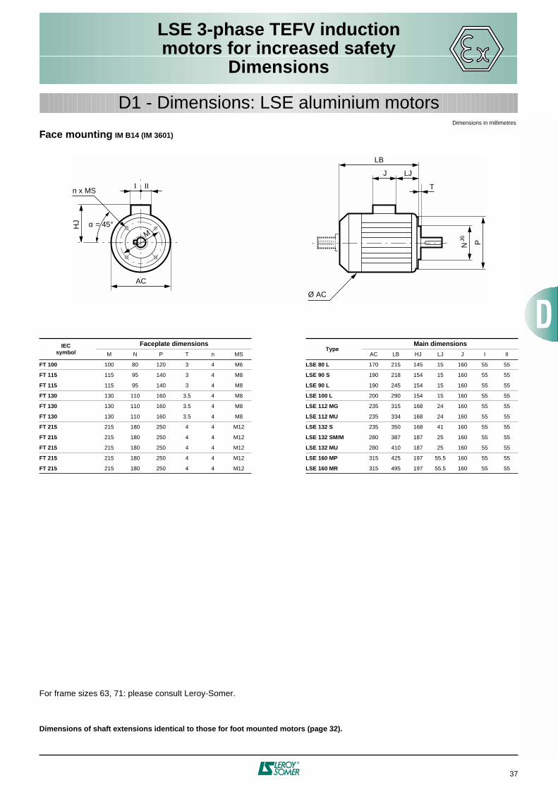
LSE 3-phase TEFV inductionmotors for increased safety
Dimensions
37
D1 - Dimensions: LSE aluminium motors
Face mounting IM B14 (IM 3601)
For frame sizes 63, 71: please consult Leroy-Somer.
Dimensions of shaft extensions identical to those for foot mounted motors (page 32).
IECsymbol
Faceplate dimensionsType
Main dimensions
M N P T n MS AC LB HJ LJ J I II
FT 100 100 80 120 3 4 M6 LSE 80 L 170 215 145 15 160 55 55
FT 115 115 95 140 3 4 M8 LSE 90 S 190 218 154 15 160 55 55
FT 115 115 95 140 3 4 M8 LSE 90 L 190 245 154 15 160 55 55
FT 130 130 110 160 3.5 4 M8 LSE 100 L 200 290 154 15 160 55 55
FT 130 130 110 160 3.5 4 M8 LSE 112 MG 235 315 168 24 160 55 55
FT 130 130 110 160 3.5 4 M8 LSE 112 MU 235 334 168 24 160 55 55
FT 215 215 180 250 4 4 M12 LSE 132 S 235 350 168 41 160 55 55
FT 215 215 180 250 4 4 M12 LSE 132 SM/M 280 387 187 25 160 55 55
FT 215 215 180 250 4 4 M12 LSE 132 MU 280 410 187 25 160 55 55
FT 215 215 180 250 4 4 M12 LSE 160 MP 315 425 197 55.5 160 55 55
FT 215 215 180 250 4 4 M12 LSE 160 MR 315 495 197 55.5 160 55 55
J LJ
LB
T
N PJ6
Ø AC
HJ
I
AC
M
n x MSII
α = 45°
Dimensions in millimetres

LSE 3-phase TEFV inductionmotors for increased safety
Dimensions
38
Optional features
Non-standard flanges
● Standard B3 ❍ Adapted shaft ✱ Adaptable without shaft modifications
Drip cover for operation in vertical position, shaft end facing down
For frame sizes 63, 71, 250 and 280: please consult Leroy-Somer.
Flange mounted (FF) Face mounted (FT)
Flangetype
Motortype F
F 1
15
FF
130
FF
165
FF
215
FF
265
FF
300
FF
350
FF
400
FF
500
FT
85
FT
100
FT
115
FT
130
FT
165
FT
215
FT
265
LSE 80 ❍ ❍ ● ✱ ✱ ● ✱ ✱ ✱
LSE 90 ✱ ✱ ● ✱ ✱ ● ✱ ❍
LSE 90 (Foot) ❍ ❍ ❍ ❍ ✱ ● ✱ ❍
LSE 100 ❍ ❍ ❍ ● ✱ ● ✱ ✱
LSE 112 MG/MU ❍ ❍ ● ✱ ✱ ● ✱ ✱
LSE 132 S ❍ ✱ ● ✱ ✱ ● ✱
LSE 132 SM/M/MU ❍ ❍ ● ❍ ✱ ● ✱
LSE 160 MP/L/MR/M ✱ ✱ ● ✱ ✱ ●
LSE 180 ● ✱
LSE 200 ✱ ● ✱
LSE 225 ● ✱
Type LB' Ø
80 LB +20 145
90 LB +20 185
100 LB +20 185
112 MG/MU LB +25 210
132 S LB +25 210
132 SM/M LB +30 240
160 MP/MR LB +30 240
160 M/L LB +36.5 265
180 MT/MR LB +36.5 265
180 L/LU LB +36.5 305
200 LT LB +36.5 305
200 L LB +36.5 350
225 MR/ST/SR LB +36.5 350
LB LB'
Ø
Dimensions in millimetres

FLSE 3-phase TEFV inductionmotors for increased safety
Dimensions
39
PAGES
Dimensions of shaft extensions .......................................................... 40
Foot mounting IM B3 (IM 1001)................................................................... 41
Foot and flange mounting IM B35 (IM 2001) ............................................. 42
Flange mounting IM B5 (IM 3001) .............................................................. 43
Foot and face mounting IM B34 (IM 2101) ................................................ 44
Face mounting IM B14 (IM 3601) ................................................................ 45
Optional features.................................................................................... 46
D2 - Dimensions: FLSE cast iron motors
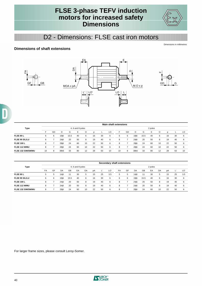
FLSE 3-phase TEFV inductionmotors for increased safety
Dimensions
40
D2 - Dimensions: FLSE cast iron motors
Dimensions of shaft extensions
For larger frame sizes, please consult Leroy-Somer.
Type
Main shaft extensions
4, 6 and 8 poles 2 poles
F GD D G E O p L LO F GD D G E O p L LO
FLSE 80 L 6 6 19j6 15.5 40 6 16 30 6 6 6 19j6 15.5 40 6 16 30 6
FLSE 90 S/L/LU 8 7 24j6 20 50 8 19 40 6 8 7 24j6 20 50 8 19 40 6
FLSE 100 L 8 7 28j6 24 60 10 22 50 6 8 7 28j6 24 60 10 22 50 6
FLSE 112 M/MU 8 7 28j6 24 60 10 22 50 6 8 7 28j6 24 60 10 22 50 6
FLSE 132 S/M/SM/MU 10 8 38k6 33 80 12 28 63 10 10 8 38k6 33 80 12 28 63 10
Type
Secondary shaft extensions
4, 6 and 8 poles 2 poles
FA GF DA GB EA OA pA L‘ LO‘ FA GF DA GB EA OA pA L‘ LO‘
FLSE 80 L 5 5 14j6 11 30 5 15 25 3.5 5 5 14j6 11 30 5 15 25 3.5
FLSE 90 S/L/LU 6 6 19j6 15.5 40 6 16 30 6 6 6 19j6 15.5 40 6 16 30 6
FLSE 100 L 8 7 24j6 20 50 8 19 40 6 8 7 24j6 20 50 8 19 40 6
FLSE 112 M/MU 8 7 24j6 20 50 8 19 40 6 8 7 24j6 20 50 8 19 40 6
FLSE 132 S/M/SM/MU 8 7 28j6 24 60 10 22 50 6 8 7 28j6 24 60 10 22 50 6
E
D
M.O x p
EA
DA
L' LO'
MOA x pA
F
GD G
FA
GF GB
LLO
Dimensions in millimetres

FLSE 3-phase TEFV inductionmotors for increased safety
Dimensions
41
D2 - Dimensions: FLSE cast iron motors
Foot mounting IM B3 (IM 1001)
For larger frame sizes, please consult Leroy-Somer.
TypeMain dimensions
A AB B BB C X AA K HA H AC HD LB LJ J I II CA
FLSE 80 L 125 157 100 130 50 20 32 9 10 80 160 230 214 27 126 63 63 68
FLSE 90 S 140 172 100 160 56 22 34 9 11 90 185 250 243 22 126 63 63 93
FLSE 90 L 140 172 125 160 56 22 34 9 11 90 185 250 243 22 126 63 63 68
FLSE 90 LU 140 172 125 160 56 22 34 9 11 90 185 250 263 22 126 63 63 88
FLSE 100 L 160 200 140 174 63 22 42 12 12 100 226 293 323 37 150 75 75 125
FLSE 112 M 190 230 140 174 70 22 45 12 12 112 226 305 323 37 150 75 75 119
FLSE 112 MU 190 230 140 174 70 22 45 12 12 112 226 305 342 37 150 75 75 138
FLSE 132 S 216 255 140 223 89 31 58 12 15 132 264 345 387 28 150 75 75 164
FLSE 132 M 216 255 178 223 89 31 58 12 15 132 264 345 387 28 150 75 75 126
FLSE 132 MU 216 255 178 223 89 31 58 12 15 132 264 345 410 28 150 75 75 149
J LJ
LB
Ø AC
x
B C
BB
CAA
HD
H HA
AB
AA4 Ø K
I II
Dimensions in millimetres

FLSE 3-phase TEFV inductionmotors for increased safety
Dimensions
42
D2 - Dimensions: FLSE cast iron motors
Foot and flange mounting IM B35 (IM 2001)
For larger frame sizes, please consult Leroy-Somer.
Dimension CA and shaft extensions are identical to those for foot mounted motors (page 40).
TypeMain dimensions
A AB B BB C X AA K HA H AC HD LB LJ J I II Sym.
FLSE 80 L 125 157 100 130 50 20 32 9 10 80 160 230 214 27 126 63 63 FF 165
FLSE 90 S 140 172 100 160 76 22 34 9 11 90 185 250 263 22 126 63 63 FF 165
FLSE 90 L 140 172 125 160 76 22 34 9 11 90 185 250 263 22 126 63 63 FF 165
FLSE 90 LU 140 172 125 160 76 22 34 9 11 90 185 250 283 22 126 63 63 FF 165
FLSE 100 L 160 200 140 174 63 22 42 12 12 100 226 293 323 37 150 75 75 FF 215
FLSE 112 M 190 230 140 174 70 22 45 12 12 112 226 305 323 37 150 75 75 FF 215
FLSE 112 MU 190 230 125 160 76 22 45 12 12 112 226 305 342 37 150 75 75 FF 215
FLSE 132 S 216 255 140 223 89 31 58 12 15 132 264 345 387 28 150 75 75 FF 265
FLSE 132 M 216 255 178 223 89 31 58 12 15 132 264 345 387 28 150 75 75 FF 265
FLSE 132 MU 216 255 178 223 89 31 58 12 15 132 264 345 410 28 150 75 75 FF 265
A
HD
H
I IIH
A
AB
AA
M
n Ø S
4 Ø K
LA
J LJ
LB
T
x
CA B C
N PJ6
Ø AC
BB
α
Dimensions in millimetres
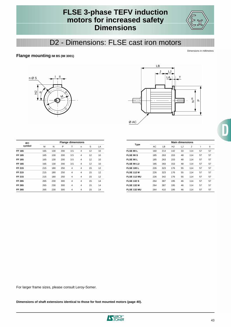
FLSE 3-phase TEFV inductionmotors for increased safety
Dimensions
43
Flange mounting IM B5 (IM 3001)
For larger frame sizes, please consult Leroy-Somer.
Dimensions of shaft extensions identical to those for foot mounted motors (page 40).
IECsymbol
Flange dimensionsType
Main dimensions
M N P T n S LA AC LB HJ LJ J I II
FF 165 165 130 200 3.5 4 12 10 FLSE 80 L 160 214 142 33 114 57 57
FF 165 165 130 200 3.5 4 12 10 FLSE 90 S 185 263 153 48 114 57 57
FF 165 165 130 200 3.5 4 12 10 FLSE 90 L 185 263 153 48 114 57 57
FF 165 165 130 200 3.5 4 12 10 FLSE 90 LU 185 283 153 48 114 57 57
FF 215 215 180 250 4 4 15 12 FLSE 100 L 226 323 176 55 114 57 57
FF 215 215 180 250 4 4 15 12 FLSE 112 M 226 323 176 55 114 57 57
FF 215 215 180 250 4 4 15 12 FLSE 112 MU 226 342 176 55 114 57 57
FF 265 265 230 300 4 4 15 14 FLSE 132 S 264 387 195 46 114 57 57
FF 265 265 230 300 4 4 15 14 FLSE 132 M 264 387 195 46 114 57 57
FF 265 265 230 300 4 4 15 14 FLSE 132 MU 264 410 195 46 114 57 57
HJ
I II
M
n Ø S LA
J LJ
LB
T
N PJ6
Ø AC
α
Dimensions in millimetres
D2 - Dimensions: FLSE cast iron motors

FLSE 3-phase TEFV inductionmotors for increased safety
Dimensions
44
D2 - Dimensions: FLSE cast iron motors
Foot and face mounting IM B34 (IM 2101)
Dimension CA and shaft extensions are identical to those for foot mounted motors (page 40).
TypeMain dimensions
A AB B BB C X AA K HA H AC HD LB LJ J I II Sym.
FLSE 80 L 125 157 100 130 50 20 32 9 10 80 160 230 214 27 126 63 63 FT 100
FLSE 90 S 140 172 100 160 56 22 34 9 11 90 185 250 243 22 126 63 63 FT 115
FLSE 90 L 140 172 125 160 56 22 34 9 11 90 185 250 243 22 126 63 63 FT 115
FLSE 90 LU 140 172 125 160 56 22 34 9 11 90 185 250 263 22 126 63 63 FT 115
FLSE 100 L 160 200 140 174 63 22 42 12 12 100 226 293 323 37 150 75 75 FT 130
FLSE 112 M 190 230 140 174 70 22 45 12 12 112 226 305 323 37 150 75 75 FT 130
FLSE 112 MU 190 230 140 174 70 22 45 12 12 112 226 305 342 37 150 75 75 FT 130
FLSE 132 S 216 255 140 223 89 31 58 12 15 132 264 345 387 28 150 75 75 FT 215
FLSE 132 M 216 255 178 223 89 31 58 12 15 132 264 345 387 28 150 75 75 FT 215
FLSE 132 MU 216 255 178 223 89 31 58 12 15 132 264 345 410 28 150 75 75 FT 215
A
HD
H HA
AB
AA4 Ø K
I
M
n Ø M.S II
J LJ
LB
T
N PJ6
Ø AC
x
B C
BB
CA
α
Dimensions in millimetres

FLSE 3-phase TEFV inductionmotors for increased safety
Dimensions
45
D2 - Dimensions: FLSE cast iron motors
Face mounting IM B14 (IM 3601)
Dimensions of shaft extensions identical to those for foot mounted motors (page 40).
IECsymbol
Faceplate dimensionsType
Main dimensions
M N P T n MS AC LB HJ LJ J I II
FT 100 100 80 120 3 4 M6 FLSE 80 L 160 214 150 27 126 63 63
FT 115 115 95 140 3 4 M8 FLSE 90 S 185 243 162 22 126 63 63
FT 115 115 95 140 3 4 M8 FLSE 90 L 185 243 162 22 126 63 63
FT 115 115 95 140 3 4 M8 FLSE 90 LU 185 263 162 22 126 63 63
FT 130 130 110 160 3.5 4 M8 FLSE 100 L 226 323 193 37 150 75 75
FT 130 130 110 160 3.5 4 M8 FLSE 112 M 226 323 193 37 150 75 75
FT 130 130 110 160 3.5 4 M8 FLSE 112 MU 226 342 193 37 150 75 75
FT 215 215 180 250 4 4 M12 FLSE 132 S 264 387 213 28 150 75 75
FT 215 215 180 250 4 4 M12 FLSE 132 M 264 387 213 28 150 75 75
FT 215 215 180 250 4 4 M12 FLSE 132 MU 264 410 213 28 150 75 75
J LJ
LB
T
N PJ6
Ø AC
HJ
I
AC
M
n x MSII
α = 45°
Dimensions in millimetres
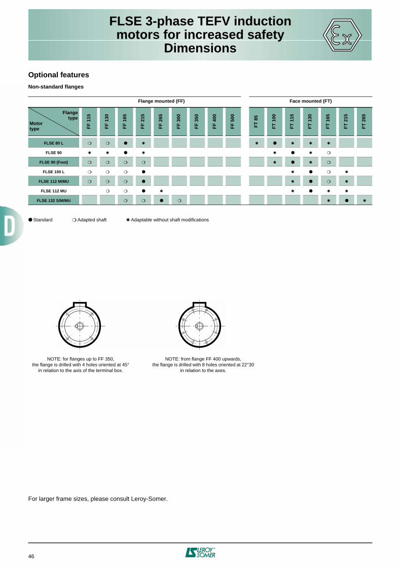
FLSE 3-phase TEFV inductionmotors for increased safety
Dimensions
46
Optional features
Non-standard flanges
● Standard ❍ Adapted shaft ✱ Adaptable without shaft modifications
For larger frame sizes, please consult Leroy-Somer.
Flange mounted (FF) Face mounted (FT)
Flangetype
Motortype F
F 1
15
FF
130
FF
165
FF
215
FF
265
FF
300
FF
350
FF
400
FF
500
FT
85
FT
100
FT
115
FT
130
FT
165
FT
215
FT
265
FLSE 80 L ❍ ❍ ● ✱ ✱ ● ✱ ✱ ✱
FLSE 90 ✱ ✱ ● ✱ ✱ ● ✱ ❍
FLSE 90 (Foot) ❍ ❍ ❍ ❍ ✱ ● ✱ ❍
FLSE 100 L ❍ ❍ ❍ ● ✱ ● ❍ ✱
FLSE 112 M/MU ❍ ❍ ❍ ● ✱ ● ❍ ✱
FLSE 112 MU ❍ ❍ ● ✱ ✱ ● ✱ ✱
FLSE 132 S/M/MU ❍ ❍ ● ❍ ✱ ● ✱
NOTE: for flanges up to FF 350,the flange is drilled with 4 holes oriented at 45°
in relation to the axis of the terminal box.
NOTE: from flange FF 400 upwards,the flange is drilled with 8 holes oriented at 22°30
in relation to the axes.
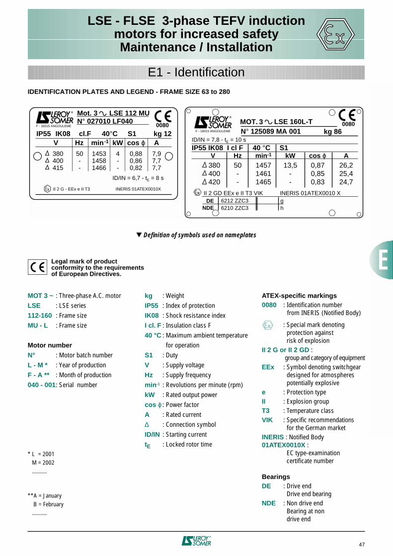
47
LSE - FLSE 3-phase TEFV inductionmotors for increased safetyMaintenance / Installation
E1 - Identification
IDENTIFICATION PLATES AND LEGEND - FRAME SIZE 63 to 280
▼
Definition of symbols used on nameplates
Legal mark of productconformity to the requirementsof European Directives.
MOT.
V Hz min-1 kW cos ϕ A
N° 125089 MA 001 kg 86
DENDE
0080
II 2 GD EEx e II T3 VIK
F - 16015 ANGOULEME
INERIS 01ATEX0010 X
380400420
13,5--
145714611465
0,870,850,83
50--
26,225,424,7
6212 ZZC36210 ZZC3
gh
LSE 160L-T3Mot. 3 LSE 112 MU N° 027010 LF040
IP55 IK08
IP55 IK08 I cl F 40 °C S1
cl.F 40°C S1 kg 12V Hz min-1 kW cos ϕ A
380400415
ID/IN = 6,7 - tE = 8 s
ID/IN = 7,8 - tE = 10 s
50--
145314581466
4--
0,880,860,82
7,97,77,7
II 2 G - EEx e II T3
F - 16015 ANGOULEME 0080
INERIS 01ATEX0010X
MOT 3 ~
: Three-phase A.C. motor
LSE
: LSE series
112-160
: Frame size
MU - L
: Frame size
Motor number
N°
: Motor batch number
L - M *
: Year of production
F - A **
: Month of production
040 - 001
: Serial number
* L = 2001M = 2002
..........
**A = January B = February
..........
kg
: Weight
IP55
: Index of protection
IK08
: Shock resistance index
I cl. F
: Insulation class F
40 °C
: Maximum ambient temperature for operation
S1
: Duty
V
: Supply voltage
Hz
: Supply frequency
min
-1
: Revolutions per minute (rpm)
kW
: Rated output power
cos
ϕ
: Power factor
A
: Rated current
∆
: Connection symbol
ID/IN
: Starting current
t
E
: Locked rotor time
ATEX-specific markings
0080
: Identification number from INERIS (Notified Body)
: Special mark denoting protection against risk of explosion
II 2 G or II 2 GD
: group and category of equipment
EEx
: Symbol denoting switchgear designed for atmospheres potentially explosive
e
: Protection type
II
: Explosion group
T3
: Temperature class
VIK
: Specific recommendations for the German market
INERIS
: Notified Body
01ATEX0010X
: EC type-examination certificate number
Bearings
DE
: Drive end Drive end bearing
NDE
: Non drive end Bearing at non drive end

48
LSE - FLSE 3-phase TEFV inductionmotors for increased safetyMaintenance / Installation
E2 - Documentation - Manuals
Warning:
unless the manufacturer’s agreement has been obtained in writing, any intervention which might affect the motor protection
type is the responsibility of the person carrying out the work.
Each motor is supplied with accompanying documentswhich must be handed to the END USER:- the EC Declaration of Conformity and Incorporation- the Instruction Manual consisting of:• Recommendations for storing and installing
induction motors.• Special manual for 3-phase induction motors
for explosive gas-filled atmospheres (2G)or gas-filled dusty atmospheres (2GD).
If lost, these documentswill be supplied on request.
LEROY-SOMER manufactures, in itsISO 9001 - Edition 2000 qualifiedproduction units, products certified byNotified Bodies: INERIS, LCIE, etc
Notes

Ref. : 3090 - 4.4 / a - 12.98 - 091298 -
GENERAL CONDITIONS OF SALE
LEROY-SOMER
I - APPLICATION AREA
Acceptance of our tenders or the placing of any order with usimplies acceptance of the following conditions without exceptionor reservation. These conditions of sale shall prevail over allstipulations appearing on the customer's purchase order, hisgeneral conditions of purchase or any other documentemanating from him and / or a third party.A dispensation from these General Conditions of Sale appliesto sales concerning foundry parts, which are subject to theEuropean Foundries General Conditions of Sale, latest edition.
II - ORDERS
All orders, including those taken by our agents andrepresentatives, by whatever mode of transmission, becomevalid only after we have accepted them in writing.We reserve the right to modify the characteristics of our goodswithout prior warning. However, the customer reserves thepossibility to specify technical specifications in the order. Unlesssuch requirements have been notified in writing, the customerwill not be able to refuse delivery of new modified goods.Our company will not accept responsibility for an incorrectchoice of goods if this incorrect choice results from incompleteand / or erroneous conditions of use, or conditions that have notbeen conveyed to the vendor by the customer.Unless otherwise specified, our tenders and estimates are onlyvalid for thirty days from the date of issue.When the goods have to satisfy standards, particularregulations and / or be inspected by standards or controlorganisations, the price request must be accompanied by fullspecifications with which we must comply with. This ismentioned in the estimate. All test and inspection fees are thecustomer's responsibility.
III - PRICE
Our prices and price lists are shown exclusive of tax and maybe revised without prior notice.Our prices are either firm for the duration specified on theestimate, or subject to revision according to a formulaaccompanying the tender which, depending on the regulations,covers a change in the cost of raw materials, products, variousservices and salaries, an index of which is published in theB.O.C.C.R.F. ("Bulletin Officiel de la Concurrence, de laConsommation et de la Répression des Fraudes").For any order of goods not found in our catalogue, requiringspecial manufacture, the invoice will include a minimum fixedsum of 600 FRF (six hundred French Francs) exclusive of tax,to cover start - up costs. Any tax due will be charged to thecustomer.All related costs, such as customs clearance and specialinspections, will be added on.Customers should remember that the French Franc (or othercurrency) is being replaced by the Single European Currency(EURO) according to a European Community ruling. Inaccordance with the general principles of monetary law,references to the French Franc will then as of right beconsidered to refer to the Euro. This substitution will beenforced on the date and in accordance with the conditionsdefined by the European Community ruling.
IV - DELIVERY
Our export sales are governed by the INCOTERMS publishedby the International Chamber of Commerce ("I.C.C.INCOTERMS"), latest edition.Goods are despatched in accordance with the conditionsindicated on our order acknowledgement, sent out in responseto any order for goods and / or services.Unless otherwise specified, our prices refer to goods put atcustomer's disposal in our factories, and include standardpackaging.Unless otherwise specified, goods are always transported at theconsignee's risk. Without exception, it is up to the purchaser toraise with the transporter, in the legal form and time limits, anyclaim concerning the condition or the number of packagesreceived and also to send us at the same time a copy of thisdeclaration. Failure to respect this procedure will relieve us of allresponsibility.In the case of CIF (Cost, Insurance & Freight) or CIP (Carriage& Insurance Paid to) sales, etc…, in the event of damage, ourresponsibility will only be engaged if any reservations andrequired declarations have been notified in the required timeperiod, and will not in any case exceed the indemnity sumreceived from our insurers.If the arrangements for despatch are modified, we reserve theright to invoice any additional costs arising from such changes.Packages cannot be returned.Should the delivery of goods be delayed for a reason notattributable to the vendor, goods will be stored on the vendor'spremises, at the own risk of the customer, at a charge forstorage of 1% (one per cent) of the total order sum per week,beginning, without a grace period, on the day after thescheduled date of delivery indicated in the contract. After thirtydays from this date, the vendor has the right to dispose of thesegoods as he wishes and arrange a new delivery date for the saidgoods with the customer. In all instances, all down paymentsreceived remain the property of the vendor as indemnity,without prejudice to other claims for damages that the vendormay wish to bring.
V - DELIVERY DATES
Delivery times are stated for information only, and do notinclude the month of August.Delivery dates are counted from the issue date of the orderacknowledgement from the vendor and are subject tocompliance with the provisions indicated on the orderacknowledgement, notably receipt of the down payment for theorder, notification of the issuance of an irrevocable letter ofcredit conforming to all vendor requirements (especially asregards the amount, currency, validity, licence, etc.) andacceptance of the terms of payment with any guarantees whichmay be required, etc…In no case does late delivery automatically entitle the customerto damages and / or penalties.Unless otherwise specified, we reserve the right to make partialdeliveries.Delivery dates are automatically suspended without formalnotice, and the vendor shall have no responsibility in cases ofForce Majeure, or events beyond the control of the vendor or hissuppliers such as delays, saturation, or unavailability of theplanned transport methods, energy, raw materials etc., serious
accidents such as fires, explosions, strikes, lock out, oremergency measures taken by the Authorities occurring afterthe conclusion of the order and preventing its normal execution.Similarly, delivery dates are automatically suspended withoutformal notice in all cases of failure to perform or late payment bythe customer.
VI - TESTS
All goods manufactured by the vendor are tested before leavingthe factory in accordance with vendor's ISO 9001 certifications.Customers may attend these tests : they simply have to conveythe wish to do so in writing when the order is placed.Specific tests and acceptance tests requested by the customer,whether conducted on the customer's premises, in our factories,on-site, or by inspection organisations, must be noted on theorder and are to be paid for by the customer.Goods specially developed for a customer will have to beapproved by the latter before any delivery of mass - producedgoods, notified by signing and returning to us the ProductApproval Schedule reference Q1. T. 034.In the event of the customer's insistence on delivery withouthaving signed this form beforehand, the goods will then still beconsidered as prototypes and the customer will assume soleresponsibility for using it or supplying it to his own customers.
VII -TERMS OF PAYMENT
All our sales are considered as carried out and payable at theregistered office of the vendor, without exception, whatever themethod of payment, the place of conclusion of the sale anddelivery.When the customer is based in France, our invoices arepayable on receipt in cash, by banker's draft, or by L.C.R.("Lettre de Change - Relevé"), within thirty days from the end ofthe month following the invoice date, net and without discount.When the customer is based outside France, our invoices arepayable in cash against delivery of the dispatching documentsor by irrevocable documentary credit confirmed by a first classFrench bank with all bank charges payable by the customer.Payments must be made in the currency of the invoice.In accordance with French Law N° 92.1442 dated December31,1992, non-payment of an invoice by its due date will giverise, after formal notice, to a penalty equal to one and a halftimes (1.5) the official rate of interest, and to late paymentinterest at the bank base rate plus five per cent. If the invoicecarries V.A.T. (Value Added Tax), this is calculated on theamount, inclusive of tax, of the remaining sum due and comesinto force from the due date.Should steps have to be taken to recover the said amount, asurcharge of 15% (fifteen per cent) of the sum demanded will bepayable.Moreover, as a consequence of non - payment of an invoice orany term of payment, whatever the method of paymentenvisaged, the customer shall pay immediately for the whole ofthe outstanding amount owed to the vendor (including hissubsidiaries, sister or parent companies, whether in France oroverseas) for all deliveries or services, whatever their initial duedate.Notwithstanding any particular terms of payment arrangedbetween the parties concerned, the vendor reserves the right todemand :
– payment in cash, before the goods leave the factory, for allorders in the process of manufacture, in the event of a problemwith payment, or if the customer's financial situation justifies it,– a down payment for the order.
Unless we are at fault, all down payments are non - returnable,without prejudice to our right to claim damages.Any payment made in advance of the fixed payment date willlead to a discount of 0.2 % (zero point two per cent) per monthof the amount concerned.
VIII - COMPENSATION CLAUSE
Unless prohibited by law, the vendor and the customerexpressly agree between one another to compensate theirrespective debts arising from their commercial relationship,even if the conditions defined by law for legal compensation arenot all satisfied.In applying this clause, by vendor we mean any company in theLEROY SOMER group.
IX - TRANSFER OF RISKS - TRANSFERT OF TITLE
Transfer of risks occurs upon the handing over of the goods,according to the delivery conditions agreed at the time ofordering.THE TRANSFER OF TITLE OF THE GOODS SOLD TO THECUSTOMER OCCURS UPON PAYMENT OF THE WHOLEPRINCIPAL SUM AND INTEREST.The provision of a document creating an obligation to pay (bankdraft or similar) does not constitute payment.So long as the price has not been paid in full, the customer isobliged to inform the vendor, within twenty - four hours, of theseizure, requisition or confiscation of goods to the benefit of athird party, and to take all safety measures to acquaint otherswith and respect our right of title in the event of intervention bycreditors.Failure to pay the amount due, whether total or partial, on thedue date, for whatever reason and on whatever grounds,authorises the vendor to demand as of right and without formalnotice, the return of the goods, wherever they may be, at thecustomer's expense and risk.Return of the goods does not imply to cancellation of the sale.However, we reserve the option to apply the cancellationclause contained in these General Conditions of Sale.
X - CONFIDENTIALITY
The vendor and the customer undertake to maintainconfidentiality of information of a technical, commercial or othernature, obtained during negotiations and / or the execution ofany order.
XI - INDUSTRIAL AND INTELLECTUAL PROPERTY RIGHTS
The results, data, studies and information (whether patentableor not), or software developed by the vendor during executionof any order, and delivered to the customer, are the soleproperty of the vendor.Apart from the instructions for use, servicing and maintenance,reports and documents of any type that we deliver to ourcustomers remain our property and must be returned to us on
request, even when design fees have been charged for them,and they shall not be communicated to third parties or usedwithout the prior written agreement of the vendor.
XII - CANCELLATION CLAUSE
We reserve the right to cancel immediately, as of right andwithout formal notice, the sale of our goods in case of non-payment of any part of the price by the due date, or in case ofany breach in the contractual obligations of the customer. In thiscase, the goods will have to be returned to us immediately, atthe customer's own risk and expense, subject to a penalty of10% (ten per cent) of its value per week of delay. All paymentsalready received shall remain our property as indemnity, withoutprejudice to our rights to claim damages.
XIII -WARRANTY
The vendor warrants the goods against any defect, arising froma default in material or in workmanship, for twelve monthsstarting from the date on which they are made available,according to the conditions defined below.The warranty for goods with special applications, or goods used24 hours a day, is automatically reduced by half.On the other hand, parts or accessories of other origin, whichbear their own brand name, are included in our warranty only tothe extent of the warranty conditions granted by the suppliers ofthese parts.The vendor's warranty will only apply insofar as the goods havebeen stored, used and maintained in accordance with thevendor's instructions and documentation. It cannot be invokedwhen the default results from :
– failure to monitor, maintain or store the goods correctly,– normal wear and tear of goods,– intervention on or modification to the goods without thevendor's prior authorisation in writing,– abnormal use, or use not conforming to the intended purpose, – defective installation at the customer's and / or the final user'spremises,– non-communication, by the customer, of the intended purposeor the conditions of use of the goods,– failure to use original manufacturer's spare parts,– Force Majeure or any event beyond the control of the vendor,– etc …
In all cases, the warranty is limited to the replacement or therepair of parts or goods recognised as defective by our technicaldepartments. If the repair is entrusted to a third party, it shouldonly be carried out after acceptance by the vendor of theestimate for repair.No goods should be returned without the vendor's priorauthorisation in writing .Goods to be repaired should be sent prepaid, to the addressindicated by the vendor. If the goods have not been repairedunder warranty, the cost of dispatching it back will be invoicedto the customer or to the end purchaser.This warranty applies to our goods in accessible form andtherefore does not cover the cost of dismantling andreinstallation of the said goods in the equipment in which theyare integrated .Repair, modification, or replacement of spare parts or goodsduring the warranty period will not extend the duration of thewarranty.The provisions of this article constitute the only obligation on thepart of the vendor concerning the warranty for the goodssupplied.
XIV -LIABILITY
The vendor will be liable for bodily injury caused by his goods orpersonnel.The repair of property damages attributable to the vendor isexpressly limited to a sum which may not exceed the amount ofthe goods found as defective.It is expressly agreed that the vendor and the customer eachwaive any right to claim for indirect, consequential and / orpunitive damages of any kind, such as loss of production, lossof profit, costs of withdrawal from the market or costs of recall,costs of dismantling and reinstallation of goods, loss ofcontracts, etc.
XV - SPARE PARTS AND ACCESSORIES
Spare parts and accessories are provided on request insofar asthey are available. Related costs (carriage and any other costs)are always added to the invoice.We reserve the right to demand a minimum quantity or invoicea minimum per order.
XVI - PARTIAL INVALIDITY
If any provision of these General Conditions of Sale is held to beunenforceable for any reason, it shall be adjusted rather thanvoided, if possible, in order to achieve the intent of the parties tothe extent possible. In any event, all other provisions shall bedeemed valid and enforceable to the full extent possible.
XVII -DISPUTESTHESE GENERAL CONDITIONS OF SALE ARE GOVERNEDBY FRENCH LAW.ANY DISPUTE RELATING TO OUR SALES, EVEN IN THECASE OF MULTIPLE DEFENDANTS, SHALL BE, IN THEABSENCE OF AMICABLE SETTLEMENT ANDNOTWITHSTANDING ANY CLAUSE TO THE CONTRARY,SUBJECT TO THE JURISDICTION OF THE COURTS OFANGOULEME (France).

LEROY-SOMER 16015 ANGOULÊME CEDEX - FRANCE
RCS ANGOULÊME N° B 671 820 223S.A. au capital de 62 779 000
€
www.leroy-somer.com