3-phase tefv induction motors atex gas - zones 1 & 2
TRANSCRIPT

3-phase TEFV induction motorsATEX GAS - Zones 1 & 2
Technical catalogue
4428
en
- 201
0.11
/ a

2
With its 10,000-strong workforce, Leroy-Somer has created an
international network of 470 centres of expertise and service centres
capable of offering you the technical support you need, 24 hours a day,
7 days a week throughout the world.
To strengthen our commitment to the Oil and Chemicals market,
Leroy-Somer has assembled a multidisciplinary team of highly
qualified engineers to undertake global project management. Our
R&D departments are directly involved in creating standard solutions
dedicated to the new standards relating to potentially explosive
atmospheres.
A WORLDWIDE GROUP AT YOUR SERVICE

3
3-phase TEFV induction motorsATEX GAS - Zones 1 & 2
4P1500 min-1 FLSD 100 L 3 kW IM 1001
IM B3230 /400 V 50 Hz IP 55
Ex d II B T4II 2 G
2
1
3
Designation
The complete motor reference described below will enable you to order the desired equipment.
The selection method consists of following the terms in the designation.
No. of polesSpeed(s)
Series designation
Frame sizeIEC 60072-1
Housing designation
Number and type of cable glands
Description of cables
Rated output power
Mounting arrangementIEC 60034-7
Mains voltage
Mains frequency
IEC 60034-5 protection

4
3-phase TEFV induction motorsATEX GAS - Zones 1 & 2
FLSDCast iron frame0.18 to 400 kWEx d (or de) II B T4 - Ex d (or de) II C T4Flameproof induction motors
EN 60079-0Complies with EN 60079-1
EN 60079-7
Zone 1: II 2 G Category 2
Other versions can also be selected:
Ex d II B T5
Ex d II C T5
Example of marking:Ex
Distinctive community mark
Symbol for equipment designed to comply with European standards
Symbol specifying the protection type
Explosion group
Gas subdivision
Temperature class
EC type-examination certificate number
d II B T4 INERIS 01 ATEX 0001X
Versions also available with type "e" terminal box.
(F)LSECast iron or aluminium frame0.75 to 55 kWEx e II T3Increased safety induction motors
EN 60079-0EN 60079-7
Other versions can also be selected:Ex e II T3 VIKEx e II T4
Complies with

5
3-phase TEFV induction motorsATEX GAS - Zones 1 & 2
(F)LSNCast iron or aluminium frame0.37 to 675 kWEx nA II T3Non-sparking induction motors
EN 60079-0EN 60079-15
Zone 2: II 3 G Category 3
Gas and Dust dual environment
EN 60079-0/EN 60079-1/EN 60079-7/EN 60079-15EN 61241-0/EN 61241-1
Zone 1 + 21: II 2 GD Dual marking
FLSD Ex d (or de) IIB T4 Ex tD A21 IP65 T125°CFLSD Ex d (or de) IIB T5 Ex tD A21 IP65 T100°C(F)LSE Ex e II T3 Ex tD A21 IP65 T125°C
Zone 2 + 22: II 3 GD Dual marking
(F)LSN Ex nA II T3 Ex tD A22 IP55 T125°C
An nA II T3 VIK version is also available
Complies with
Complies with

6
3-phase TEFV induction motorsATEX GAS - Zones 1 & 2
PAGE
- GENERAL INFORMATION
Quality assurance ................................................................ 9
General standardization ................................................... 10
Tolerance on main performance parameters .................. 12
Definition of atmospheres and zones ............................. 13Atmospheres at risk of explosion ........................................ 13Definition of hazardous areas ............................................. 13Explosion group classification ............................................. 13Temperature classes........................................................... 13
Classification of common gases (indicative values) ..... 14
Definition of equipment .................................................... 15Types of protection.............................................................. 15Comparison of USA/European standards ........................... 15
Installation rules for surface industries .......................... 16Regulation relating to zones at risk of explosion caused by gas and vapours ............................................................. 16Choice of equipment depending on the zone ...................... 16Installation technologies ..................................................... 16
Conditions of use .............................................................. 17Normal operating conditions ............................................... 17Motor used with frequency inverter ..................................... 17Power correction ................................................................. 17Severe environment............................................................ 17V.I.K. version for German heavy industry ............................ 17
- ENVIRONMENT
Definition of “Index of Protection” (IP/IK) ........................ 18
Heaters .............................................................................. 19Space heaters..................................................................... 19D.C. injection ...................................................................... 19A.C. injection....................................................................... 19
External finish ................................................................... 20
PAGE
- CONSTRUCTION
Description of FLSD flameproof motors: Ex d II B T4 ..... 21
Other descriptions of FLSD flameproof motors ............. 22Variants: FLSD cast iron motors with increased safety terminal box Ex d e IIB ........................................................ 22FLSD cast iron motors in version Ex d IIC and Ex d e IIC .... 22
Description of (F)LSE increased safety motors: Ex "e" and (F)LSN non-sparking motors: Ex "nA" ......... 23
Mounting arrangements ................................................... 24
Bearings and lubrication .................................................. 25Lubrication of bearings........................................................ 25Grease life .......................................................................... 27Standard bearing fitting arrangements ................................ 27
Axial load of FLSD motors ............................................... 28Permissible axial load (in daN) on main shaft extension for standard bearing assemblyin FLSD flameproof motors ................................................. 28
Axial load of LSE/LSN motors .......................................... 31Permissible axial load (in daN) on main shaft extension for standard bearing assemblyin LSE/LSN increased safety and non-sparking motors with aluminium frame .............................................. 31
Axial load of FLSE/FLSN motors ..................................... 34Permissible axial load (in daN) on main shaft extension for standard bearing assemblyin FLSE/FLSN increased safety and non-sparking motors with cast iron frame ................................................. 34
Mains connection ............................................................. 37Positions of the terminal box and cable gland ..................... 37Power supply cables ........................................................... 38Number and type of adaptable cable glands on type “d” terminal box for FLSD flameproof motors............................ 38Type of adaptable cable glands on type “e” terminal box for FLSD flameproof - (F)LSE increased safety - (F)LSN non-sparking motors ........................................................... 38Power supply terminals - direction of rotation ...................... 39Wiring diagrams .................................................................. 39Earth terminals.................................................................... 39
Contents
Copyright 2010: MOTEURS LEROY-SOMER
Leroy-Somer reserves the right to modify the characteristics of its products at any time in order to incorporate the latest technological developments.The information contained in this document may therefore be changed without notice.

7
3-phase TEFV induction motorsATEX GAS - Zones 1 & 2
PAGE
- OPERATION
Weighted sound level [dB(A)] ........................................... 40
Motor vibration levels - Balancing ................................... 41
- ELECTROMECHANICAL CHARACTERISTICSFLSD FLAMEPROOF - ZONE 1
Selection data .................................................................... 442 poles - 3000 min-1 ............................................................. 444 poles - 1500 min-1 ............................................................. 456 poles - 1000 min-1 ............................................................. 468 poles - 750 min-1 .............................................................. 47
Dimensions ....................................................................... 48Shaft extensions ................................................................. 48Foot mounted IM B3 (IM 1001)............................................ 49Foot and flange mounted IM B35 (IM 2001) ........................ 50Flange mounted IM B5 (IM 3001) IM V1 (IM 3011) .............. 51Foot and face mounted IM B34 (IM 2101) ........................... 52Face mounted IM B14 (IM 3601) ......................................... 53
- ELECTROMECHANICAL CHARACTERISTICSFLSE INCREASED SAFETY - ZONE 1FLSN NON-SPARKING - ZONE 2
Selection data for FLSE increased safety - zone 1 .......... 562 poles - 3000 min-1 - Ex e II T3 ........................................... 564 poles - 1500 min-1 - Ex e II T3 ........................................... 576 poles - 1000 min-1 - Ex e II T3 ........................................... 582 poles - 3000 min-1 - Ex e II T4 ........................................... 594 poles - 1500 min-1 - Ex e II T4 ........................................... 60
Selection data for FLSN non-sparking - zone 2 ............... 622 poles - 3000 min-1 - Ex nA II T3 ......................................... 624 poles - 1500 min-1 - Ex nA II T3 ......................................... 636 poles - 1000 min-1 - Ex nA II T3 ......................................... 648 poles - 750 min-1 - Ex nA II T3 .......................................... 65
FLSE - FLSN dimensions .................................................. 66Shaft extensions ................................................................. 66Foot mounted IM B3 (IM 1001)............................................ 67Foot and flange mounted IM B35 (IM 2001) ........................ 68Flange mounted IM B5 (IM 3001) ........................................ 69Foot and face mounted IM B34 (IM 2101) ........................... 70Face mounted IM B14 (IM 3601) ......................................... 71
PAGE
- ELECTROMECHANICAL CHARACTERISTICSLSE INCREASED SAFETY - ZONE 1LSN NON-SPARKING - ZONE 2
Selection data for LSE increased safety - zone 1 ............ 742 poles - 3000 min-1 - Ex e II T3 ........................................... 744 poles - 1500 min-1 - Ex e II T3 ........................................... 756 poles - 1000 min-1 - Ex e II T3 ........................................... 762 poles - 3000 min-1 - Ex e II T4 ........................................... 774 poles - 1500 min-1 - Ex e II T4 ........................................... 78
Selection data for LSN non-sparking - zone 2 ................. 802 poles - 3000 min-1 - Ex nA II T3 ......................................... 804 poles - 1500 min-1 - Ex nA II T3 ......................................... 816 poles - 1000 min-1 - Ex nA II T3 ......................................... 828 poles - 750 min-1 - Ex nA II T3 .......................................... 83
LSE - LSN dimensions ....................................................... 84Shaft extensions ................................................................. 84Foot mounted IM B3 (IM 1001)............................................ 85Foot and flange mounted IM B35 (IM 2001) ........................ 86Flange mounted IM B5 (IM 3001) ........................................ 87Foot and face mounted IM B34 (IM 2101) ........................... 88Face mounted IM B14 (IM 3601) ......................................... 89
- OPTIONAL FEATURES
Electrical options .............................................................. 90Thermal protection .............................................................. 90
Mechanical options .......................................................... 91Terminal box ....................................................................... 91Adaptation for vibration sensor ........................................... 92Draining of condensation .................................................... 92Tapped holes for positioning ............................................... 92Radial seal .......................................................................... 92Forced ventilation ............................................................... 93Encoders ............................................................................ 93Roller bearings.................................................................... 93Flying leads......................................................................... 93Non-standard flanges ......................................................... 94Drip cover ........................................................................... 97
Contents

8
3-phase TEFV induction motorsATEX GAS - Zones 1 & 2
PAGE
Altitude .............................................................................. 17Ambient temperature ......................................................... 17Auxiliary terminal box ......................................................... 91
Balancing...................................................................... 41-42Bearings ............................................................................ 26
Cable glands ...................................................................... 38Cables ............................................................................... 38Certification.......................................................................... 9Condensation .................................................................... 92Connection ........................................................................ 37Connection ........................................................................ 39
Degree of protection .......................................................... 18Dimensions .................................... 48 to 53-66 to 71-84 to 89Direction of rotation ............................................................ 39Drip cover .......................................................................... 97
Earth terminals................................................................... 39Earthing ............................................................................. 39Electrical and mechanical characteristics ................. 43 to 89Encoder ............................................................................. 93Environment ...................................................................... 17Explosion groups ............................................................... 14
Fan cover .................................................................. 21 to 23Flameproof casing ........................................................ 15-21Flanges ..................................................................... 94 to 96Flying leads........................................................................ 93Forced ventilation .............................................................. 93Frequency control .............................................................. 17
Gas .................................................................................... 14Greasing ............................................................................ 26
Identification ........................................................................ 3Ignition temperature ...................................................... 13-14Increased safety ..................................................... 15-22-23
Lifting rings ................................................................... 21-23Lubrication .................................................................... 25-26
Marking ............................................................................. 4-5Mounting arrangements ..................................................... 24
NEC ................................................................................... 15NEMA ................................................................................ 15Noise ................................................................................. 40
Official accreditation laboratories ......................................... 9Operating positions ............................................................ 24
PAGE
Paint .................................................................................. 20Permissible axial load ............................................... 28 to 36Potentially explosive atmospheres..................................... 13
Quality assurance ................................................................ 9
Responsibility of the person carrying out the work ............. 16
Space heaters.................................................................... 19Standards ..................................................................... 10-11Surface temperature .......................................................... 13
Tapped holes for positioning .............................................. 92Terminal blocks .................................................................. 39Terminal box ........................................................ 21 to 23-37Thermal protection ............................................................. 90Tolerances ......................................................................... 12Types of protection............................................................. 15
Variable speed ................................................................... 17Vibration ....................................................................... 41-42Vibration sensor ................................................................. 92VIK ..................................................................................... 17
Zones............................................................................ 13-16
Index

9
ISO 9001 : 2000
3-phase TEFV induction motorsATEX GAS - Zones 1 & 2
General information
A1 - Quality assuranceLEROY-SOMER's quality management system is based on:- Control of procedures right from the initial sales offering until delivery to the customer, including design, manufacturing start-up and production- A total quality policy based on making continuous progress in improving operational procedures, involving all departments in the company in order to give customer
satisfaction as regards delivery times, conformity and cost
- Indicators used to monitor procedure performance.
- Corrective actions and advancements with tools such as FMECA, QFD, MAVP, MSP/MSQ and Hoshin type improvement workshops on flows, process re-engineering, plus Lean Manufacturing and Lean Office.
- Annual surveys, opinion polls and regular visits to customers in order to ascertain and detect their expectations.Personnel are trained and take part in the analyses and actions for continuously improving the procedures.
CERTIFICATIONThe ATEX motors presented in this catalogue comply with the national and/or international standards governing the construction of this type of equipment.EC type-examination certificates are drawn up by notified bodies, in accordance with the European Community Council Directive 94/9/EC known as ATEX.Approval is obtained when descriptive documents have been examined and validated, and tests performed. These include tests involving heating and explosion of the equipment.EC-type examination certificates granted by the bodies listed opposite are recognized by all EC countries.Approved equipment is authorized to carry the CE mark or the distinctive community mark
LEROY-SOMER has entrusted the certification of its expertise to various international organisations.Certification is granted by independent professional auditors, and recognises the high standards of the company's quality assurance procedures.All activities resulting in the final version of the machine have therefore received official certification ISO 9001: 2000 from the DNV.Similarly, our environmental approach has enabled us to obtain certification ISO 14001: 2004.Products for particular applications or those designed to operate in specific environments are also approved or certified by the following organisations: INERIS, LCIE, DNV, BSRIA, TUV, CCC, GOST, which check their technical performance against the various standards or recommendations.

10
3-phase TEFV induction motorsATEX GAS - Zones 1 & 2
General information
ORGANIZATION OF STANDARDS AUTHORITIES
International bodies
Worldwide General standardization
ISOInternational Standards
Organisation
Electronics/electrotechnical standardization
IECInternational Electrotechnical
Commission
European CENEuropean Committee
for Standards
ECISSEuropean Committee for
Iron and Steel Standardization
CENELECEuropean Committee for Electrotechnical
Standardization
A2 - General standardization
TCCommittees
technical
SCSub-
committees
WGWorking groups
TCCommittees
technical
SCSub-
committees
WGWorking groups
TCTechnical
committees
SCSub-
committees
AHGAd hoc groups
TCTechnical committees

11
3-phase TEFV induction motorsATEX GAS - Zones 1 & 2
General information
List of standards quoted in this document
References International standards
IEC/EN 60034-1 Electrical rotating machines: ratings and operating characteristics.
IEC/EN 60034-5 Electrical rotating machines: classification of degrees of protection provided by casings of rotating machines.
IEC/EN 60034-6 Electrical rotating machines (except traction): cooling methods.
IEC/EN 60034-7 Electrical rotating machines (except traction): symbols for mounting positions and assembly layouts.
IEC 60034-8 Electrical rotating machines: terminal markings and direction of rotation.
IEC/EN 60034-9 Electrical rotating machines: noise limits.
IEC/EN 60034-12 Starting characteristics for single-speed three-phase cage induction motors for supply voltages less than or equal to 660 V.
IEC/EN 60034-14 Electrical rotating machines: mechanical vibrations of certain machines with a frame size above or equal to 56 mm. Measurement, evaluation and limits of vibrational intensity.
IEC 60034-2 Electrical rotating machines: methods for determining losses and efficiency from tests (additional losses added as a fixed percentage).
IEC 60034-2-1 Electrical rotating machines: methods for determining losses and efficiency from tests (measured additional losses).
IEC 60034-30 Electrical rotating machines: efficiency classes for single-speed three-phase cage induction motors(IE code).
IEC 60038 IEC standard voltages.
IEC 60072-1 Dimensions and power series for electrical rotating machines: designation of casings between 56 and 400 and flanges between 55 and 1080.
IEC 60085 Evaluation and thermal classification of electrical insulation.
IEC/EN 60529 Degrees of protection provided by enclosures.
IEC 60721-2-1 Classification of natural environment conditions. Temperature and humidity.
IEC 60892 Effects of an imbalance in the voltage system on the characteristics of three-phase squirrel-cage induction motors.
IEC/EN 61000-2-2 Electromagnetic compatibility (EMC): environment.
IEC guide 106 Guidelines on the specification of environmental conditions for the determination of operating characteristics of equipment.
ISO 281 Bearings - Basic dynamic loadings and nominal bearing life.
ISO/EN ISO 1680 Acoustics - Test code for measuring airborne noise emitted by electrical rotating machines: a method for establishing an expert opinion for free field conditions over a reflective surface.
ISO 8821 Mechanical vibration - Balancing. Conventions on shaft keys and related parts.
EN 60529 Degree of protection provided by electrical enclosures against extreme mechanical impacts.
New Ref. Old Ref.
EN 60079-0 EN 50014 Electrical equipment for explosive atmospheres: general regulations.
EN 60079-1 EN 50018 Electrical equipment for explosive atmospheres: "d" flameproof casings.
EN 60079-7 EN 50019 Electrical equipment for potentially explosive atmospheres: "e" increased safety.
EN 60079-14 Electrical installations in hazardous areas.
EN 60079-15 EN 50021 Electrical equipment for explosive atmospheres: "n" non-sparking.
EN 61241-0 & 1 EN 50281-1-1 Electrical apparatus for use in the presence of combustible dust.
A2 - General standardization

12
E/2
10
10
3-phase TEFV induction motorsATEX GAS - Zones 1 & 2
General information
Tolerances on electromechanical characteristicsIEC 60034-1 specifies standard tolerances for electromechanical characteristics.
Parameters Tolerances
Efficiency machines P ≤ 150 kW machines P > 150 kW
– 15% (1 – η)– 10% (1 – η)
Cos ϕ – 1/6 (1 – cos ϕ)(min 0.02 - max 0.07)
Slip machines P < 1 kW machines P ≥ 1 kW
± 30%± 20%
Locked rotor torque – 15%, + 25% of rated torqueStarting current + 20%Run-up torque – 15% of rated torqueMaximum torque – 10% of rated torque
> 1.6 MN
Moment of inertia ± 10%Noise + 3 dB (A)Vibration + 10% of the guaranteed class
Note: - IEC 60034-1 does not specify tolerances for current - the tolerance is ± 10% in NEMA-MG1
Tolerances and adjustmentsThe standard tolerances shown below are applicable to the mechanical characteristics given in our catalogues. They comply fully with the requirements of IEC standard 60072-1.
Characteristics Tolerances
Frame size H ≤ 250 ≥ 280Diameter ∅ of the shaft extension:- 11 to 28 mm- 32 to 48 mm- 55 mm and over
0, — 0.5 mm0, — 1 mm
j6k6m6
Diameter N of flange spigots j6 up to FF 500,js6 for FF 600 and over
Key width h9
Width of drive shaft keyway (normal keying)
N9
Key depth:- square section- rectangular section
h9h11
jEccentricity of shaft in flanged motorsflanged (standard class)- diameter > 10 up to 18 mm- diameter > 18 up to 30 mm- diameter > 30 up to 50 mm- diameter > 50 up to 80 mm- diameter > 80 up to 120 mm
0.035 mm0.040 mm0.050 mm0.060 mm0.070 mm
kConcentricity of spigot diameter andlperpendicularity of mating surface of flange in relation to shaft (standard class)Flange (FF) or Faceplate (FT):- F 55 to F 115- F 130 to F 265- FF 300 to FF 500- FF 600 to FF 740- FF 940 to FF 1080
0.08 mm0.10 mm
0.125 mm0.16 mm0.20 mm
A3 - Tolerance on main performance parameters
j Eccentricity of shaft in flanged motors
k Concentricity of spigot diameter
l Perpendicularity of mating surface of flange in relation to shaft

13
12
0
L
i
L
i
L
i
A B C
3-phase TEFV induction motorsATEX GAS - Zones 1 & 2
General information
A4 - Definition of atmospheres and zonesA4.1 - ATMOSPHERES AT RISK OF EXPLOSIONThis includes all explosive and potentially explosive conditions, the explosion character being permanent or potential.
Explosive atmospheres:An explosive atmosphere is an atmosphere containing a mixture of air and inflammable substances (in the form of gas, vapour, fog or mist) in such proportions thatexcessive temperature, arcs or sparks cause it to explode. The danger is permanent.
Potentially explosive atmospheres:A potentially explosive atmosphere is an atmosphere which may become explosive due to the particular local conditions. The danger is potential.
A4.2 - DEFINITION OF ZONES AT RISK OF EXPLOSIONThe international standard EN 60079-10 defines the danger zones according to the risk of encountering an explosive atmosphere as shown in the diagram opposite:
Note: Each country has similar and comple-mentary publications giving instructions on the classification of dangerous areas.
Zone 0: location where an explosive gaseous atmosphere is permanently present for long periods.
Zone 1: location where an explosive gaseous atmosphere is likely to develop during normal operation.
Zone 2: location where an explosive gaseous atmosphere is not likely to form during normal operation, and where such a development, should it occur, only lasts for a short period of time.
Note: Zone classification is the responsibility of the manager of the company where the equipment is installed.
A4.3 - EXPLOSION GROUP CLASSIFICATION A4.3.1 - Area levelsThe areas presenting explosion risks are divided into 2 groups:- Group I: Gas-prone mines.- Group II: Areas other than gas-prone mines (surface industries).This catalogue only concerns equipment in group II.
A4.3.2 - Gas classification- Group I: Only applies to mine gas (methane in mines).- Group II: The gases present are classified in 3 subdivisions A, B and C.
The A, B, C classification is defined according to the MESG (Maximum Experimental Safe Gap) which characterises the ability of a gas not to propagate ignition through a standard joint. The risks following an explosion increase from subdivision A to subdivision C.Therefore, equipment certified for use in the presence of a type C gas can also be used in the presence of a type A or B gas.
A4.4 - TEMPERATURE CLASSES A4.4.1 - Definition of temperature classes according to IEC 60079-0The temperature class is based on the maximum temperature rise in the equipment and on the ambient operating temperature.The maximum surface temperature of an electrical appliance must always be lower than the ignition temperature of the mix of gases or vapour in which it will be used.
A4.4.2 - Definition of temperature classes according to IEC 60079-7 for Ex e- T°c = temperature- DT at PN = temperature at rated power- tS = time- tE = locked rotor time- = temperature rise in normal duty- = temperature rise during locked rotor testIn the event of rotor failure and locking, an actuator must be able to disconnect the mo-tor from the supply in a period t < tE.
In order to be able to select various appliances according to their surface temperature, six temperature classes have been created.
Temperature class T1 T2 T3 T4 T5 T6
Ignition temperature > 450°C > 300°C > 200°C > 135°C > 100°C > 85°C
Max. permissible surface temperature for the equipment
450°C 300°C 200°C 135°C 100°C 85°C
tstE
Ambienttemp.
∆T at PN
Markedtemp.
T°c
B
A
PERMANENT DANGER
POTENTIAL DANGERMINIMAL DANGER
A
B

14
3-phase TEFV induction motorsATEX GAS - Zones 1 & 2
General information
Gas Ignition temperature °C Equipment temperature class Explosion group
Acetic acid 464 T1 IIA
Acetic anhydride 316 T2 IIA
Acetone 465 T1 IIA
Acetylene 305 T2 IIC
Ammonia solution 630 T1 IIA
Amyl acetate 380 T2 IIA
Benzene (pure) 498 T1 IIA
Butane n 365 T2 IIA
Butanol n 343 T2 IIA
Carbon disulphide 95 T6 IIC
Carbon monoxide 605 T1 IIB
Cyclohexanon 420 T2 IIA
Dichlorethylene 460 T1 IIA
Diesel oil DIN 51601/04.78 220 to 300 T3 IIA
Ethanal 140 T4 IIA
Ethane 472 T2 - T1 IIA
Ethyl acetate 427 T2 IIA
Ethyl alcohol 425 T2 IIA - IIB
Ethyl chloride 510 T1 IIA
Ethylene 425 T2 IIB
Ethylene glycol 235 T3 IIB
Ethylene oxide 440 T2 IIB
Ethylic ether 180 T4 IIB
Fuel EL DIN 51 603 section 1/12.81 220 to 300 T3 IIA
Fuel L DIN 51 603 section 2/10.76 220 to 300 T3 IIA
Fuels M and S DIN 51 603 section 2/10.76 220 to 300 T3 IIA
Hexane n 225 T3 IIA
Hydrogen 560 T1 IIC
Hydrosulphuric acid 270 T3 IIB
Kerosene (or fuel oil no. 1) 220 to 300 T3 IIA
Methane 537 T1 IIA
Methanol 385 T2 IIA
Methylene chloride 625 T1 IIA
Naphthalene 520 T1 IIA
Oils for motors with boiling point < 135°C 220 to 300 T3 IIA
Oleic acid 360 T2 IIB
Phenol 595 T1 IIA
Propane 450 T2 IIA
Propylene alcohol 405 T2 IIB
Special oils with boiling point < 135°C 220 to 300 T3 IIA
Tetraline (tetrahydronaphthalene) 425 T2 IIB
Toluene 482 T1 IIA
Town gas 560 T1 IIB
A5 - Classification of common gases (indicative values)

15
3-phase TEFV induction motorsATEX GAS - Zones 1 & 2
General information
A6 - Definition of equipmentA6.1 - TYPES OF PROTECTIONEuropean standards define, according to the selected type of protection, construction rules for electrical equipment which can be used in potentially explosive conditions.These protection methods each form a specific standard in addition to the EN 60079-0 standard (general rules) and are indicated by a lower case letter.These are:- d: Flameproof enclosure- e: Increased safety- nA: Non-sparking- p: Pressurized enclosure- q: Powder filling- o: Immersion in oil- i: Fail safe- m: Encapsulating
A6.1.1 - Electric motors protected by type "d" flameproof enclosure (EN 60079-1)They must satisfy, among others, the following requirements:- Resist an internal explosion of the air/gas mixture without damage to or permanent distortion of the enclosure.- Ensure that the ignition inside the enclosure cannot be transmitted to the ambient explosive atmosphere.- Present a surface temperature lower than the ignition temperature of the gas.These three conditions require:- Very robust construction of the enclosure.- Minimum joint lengths and reduced gaps so that explosion of the air/gas mixture that is present inside the enclosure is not transmitted to the ambient potentially
explosive atmosphere (end shield/housing recesses, shaftways, etc).- Limited temperature rise, taking into account unfavourable operating conditions (voltage limits) ensuring, depending on the ambient temperature, a surface temperature that is lower than the temperature class required by the type of gas present.
A6.1.2 - Electric motors protected by type "e" increased safety enclosure (EN 60079-7)The type "e" protection method concerns equipment which does not produce arcs, sparks or hot spots during normal operation. This excludes in particular all rotating machines with a commutator.This requires, amongst others, the following design features:- Special precautions to avoid the production of arcs and sparks: air distances, and minimum creepage distances between items which are powered up and, with regard to earths, absence of mechanical friction, insulation, minimum distances in ventilation systems, special materials for fans, etc.- Temperature at all points in the motor lower than the ignition temperature of the gas. This temperature must include a period with the rotor locked as defined in standard EN 60079-7.
A6.1.3 - "nA" non-sparking electric motors (EN 60079-15)The type "nA" protection method concerns equipment which generates no sparks, arcs, or hot spots, which operates in an exceptionally explosive atmosphere.
A6.2 - COMPARISON OF USA/EUROPEAN STANDARDSThe installation regulations which apply in the USA are those specified in the NEC (National Electrical Code).There is no mutual recognition between NEC and EN standards.However, American firms in Europe or the Middle East often refer to the NEC, and it is therefore important to be able to translate these standards:
NEC CENELEC
Class I Gas Group/Category II
Class II Dust Group/Category II
Class III Fibre No specific standard
Division (DIV) I Zone 0, 1 or 21
Division (DIV) II Zone 2 or 22
Group A Acetylene II C
Group B Hydrogen II C
Group C II B
Group D II A
Motors which have been granted ATEX certification by INERIS cannot be used in the USA and Canada.

16
3-phase TEFV induction motorsATEX GAS - Zones 1 & 2
General information
A7.1 - REGULATION RELATING TO ZONES AT RISK OF EXPLOSION CAUSED BY GAS AND VAPOURSIn zones at risk of explosion, electrical installations must be reduced to what is essential to the operating needs. Equipment, motors, ducting, necessary communication devices must, as far as possible, be placed outside the danger zones.European Directive ATEX 94/9/EC, concerning electrical installations of plant classified as being likely to present risks of explosion, requires in particular that the worker in an establishment:- Defines the zones where explosive atmospheres may appear.- Selects electrical equipment suitable for the previously defined zones.- Checks the conditions of installation, operation and maintenance of this equipment.The standard EN 60079-10 can be used to determine dangerous regions.
A7.2 - CHOICE OF EQUIPMENT DEPENDING ON THE ZONEAlthough harmonised construction standards exist, there is no coordinated regulation for the choice of equipment according to the zone (0, 1, 2) where it is installed, even though there is an EN 60079-0 recommendation.
Nevertheless it can be said that:
Zone 0: The entire installation must be built with fail safe category “ia”. Only control or measurement equipment can be installed there.
Zone 1:All electrical equipment used in zone 1 must be “safe”, in other words it must conform to standard 60079.This equipment should be installed in accordance with the current rules and regulations. If "d" flameproof equipment is authorized for all countries, "e" increased safety equipment may be either totally or partially accepted.
In particular:- France, Germany, Holland = totally accepted- Belgium: partially (mains box but not motors)
Zone 2:The equipment which can be used in zone 2 must be equipment that satisfies one of the two following conditions:- Meets the rules for zone 1 equipment- Conforms with the construction rules of a recognized standard for industrial electrical equipment which, during normal operation, does not generate arcs, sparks or hot surfaces which may cause ignition or an explosion. It can for instance conform to the English standard BS 5000 part 16 or to IEC 79.15. In this case, the equipment can be accompanied by a document issued by an official laboratory, or by a declaration of conformity from the manufacturer.
In all cases it is necessary to take account of the particular specifications and the internal safety rules for each industry in each country.
A7.3 - INSTALLATION TECHNOLOGIESFor installing electrical motors protected by "d" flameproof enclosures in zones at risk of explosion, there are three types of connection.1. Direct entry of cables into the "d" flameproof enclosure via cable inlets of an approved type.2. Indirect entry of cables via an "e" increased safety junction box.3. Direct entry of cables into the "d" flameproof enclosure via tubes of an approved type ("conduit" system mainly used in the United States).See EN 60079-14.
A7 - Installation rules for surface industries

17
3-phase TEFV induction motorsATEX GAS - Zones 1 & 2
General information
A8.1 - NORMAL OPERATING CONDITIONSa/ According to IEC 60034-1, motors can operate in the following normal conditions:• ambient temperature within the range -16 to +40°C• altitude less than 1000 m• atmospheric pressure: 1050 hPa (mbar)Standard EN 60079-0 concerning electrical equipment in a potentially explosive atmosphere extends the range of ambient temperatures from -20 to +40°C as standard. In this case, no additional marking is necessary on the certified equipment.Temperatures outside this range may be considered when the equipment is certified. An additional mark must therefore be added. These extensions involve special consultation.b/ FLSD motors are designed to operate in atmospheres where the relative humidity can reach 95% at 40°C.
A8.2 - MOTOR USED WITH FREQUENCY INVERTERThe certification of our safety motors makes them suitable for use with frequency inverters, as long as all necessary precautions are taken to comply with the temperature class for which they were certified, in all circumstances.Drive control by a frequency inverter can in fact result in an increase in the machine temperature rise, mainly due to the reduction in speed of the cooling fan and a significantly lower supply voltage than on the mains.To ensure safety, the motors must be fitted with thermal winding probes and a DE end shield probe for frame sizes of 160 mm or higher. In addition, the motor rated power should usually be reduced. Derating tables have been drawn up by our design offices on the basis of on-load tests conducted on a test bed and by the specifications of IEC 60034-17. Depending on the application, the desired speed range and the torque profile of the driven machine, Leroy-Somer will select the most suitable safety motor. Inverters of a type not designed for operation in a potentially explosive zone must be placed in a non-explosive zone.
For (F)LSE increased safety and (F)LSN non-sparking protection modes, a motor, of exactly the same type, must be tested on-load with a frequency inverter with identical characteristics and marks to the one it will be used with.
In some cases, it may prove necessary to use an ATEX-approved forced ventilation unit. For small motors (frame size below 160), the self-cooled standard cooling method (IC411) is nonetheless to be preferred.A device to measure the actual motor speed, using an ATEX-certified incremental or absolute encoder, can also be installed at the non-drive end of most of our safety motors.
A8.3 - POWER CORRECTIONThe power ratings of our motors are given for continuous duty (S1) at rated voltage and frequency, at up to 1000 m altitude and at a maximum ambient temperature of 40°C as standard.By derating their rated power, it is possible to use our ATEX motors in temperature conditions above 40°C (max. 60°C) and at higher altitudes than 1000 m.
Table of correction coefficients*
Alt 1000 mAlt 2 000 m
Alt 3 000 m
Alt 4 000 m
1
P1 / P
605040
1.1
0,8
0,9
T amb (°C)
* For FLSD Ex d(e) IIB or IIC T4, (F)LSN Ex nA II T3 and (F)LSE Ex e II T3 motors.
For (F)LSE Ex e II T4 motors as well as for FLSD Ex d(e) IIB and IIC T5 motors, please consult Leroy-Somer on a case-by-case basis.
A8.4 - SEVERE ENVIRONMENTSome operating conditions require special finishes for the environment: very dusty, humid, or harsh atmospheres.The essential criteria for anti-corrosion protection apply to custom components meeting the requirements of the ATEX Directive (screws and bolts, plates, cover), metal cable glands, protection of working parts (stator and rotor), special finishes.
A8.5 - V.I.K. VERSION FOR THE GERMAN HEAVY INDUSTRYATEX Ex d e IIC T4, Ex e II T3 and Ex nA II T3 motors can be built to comply with the V.I.K. recommendations issued by German
heavy industry which apply to equipment for potentially explosive atmospheres. The main characteristics with which motors manufactured in accordance with this recommendation must comply are:- Finish for corrosive environment (paint, screws and bolts, etc).- Two stainless steel nameplates, one located inside the terminal box.- Terminal box seal glued to the lid.- Drip cover if motor placed in vertical position, shaft end facing down.- For increased safety motors, a permissible locked rotor time, defined in the recommendation, longer than the standard.
A8 - Operating conditions

18
3-phase TEFV induction motorsATEX GAS - Zones 1 & 2
Environment
B1 - Definition of "Index of Protection" (IP/IK)
IP0
1
2
3
4
5
Tests Definition IP Tests Definition IK Tests Definition
1st number:Protection against solid objects Mechanical protection
∅ 50 µµ
∅ 12 µµ
No protection
Protected against solid objects larger than 12 mm(e.g. a finger)
Protected against solid objects larger than 50 mm(e.g. accidental contact with the hand)
Protected against solid objects larger than 2.5 mm(e.g. tools, wires)
∅ 2.5 µµ
Protected against solid objects larger than 1 mm(e.g. thin tools, small wires)
∅ 1 µµ
2nd number:Protection against liquids
0 No protection 00 No protection
1
15°
2
3
4
60°
5
6
7
8 ..m
0.15 m
1 m
Protected against dust (no deposits of harmful material)
Totally protected against any dust penetration
Protected against prolonged effects of immersion under pressure
Protected against the effects of immersion between 0.15 and 1 m
Protected against projected water comparable to big waves
Projected against jets of water from all directions from a hose
Protected against projected water from all directions
Protected against rain falling at up to 60° from the vertical
Protected against water drops falling at up to 15° from the vertical
Protected against water drops falling vertically(condensation)
01 Impact energy:0.15 J
02 Impact energy:0.20 J
03 Impact energy:0.37 J
05 Impact energy:0.70 J
07 Impact energy:2 J
09 Impact energy:10 J
150 g
10 cm
250 g
15 cm
250 g
20 cm
250 g40 cm
0.5 kg40 cm
2.5 kg40 cm
. . m
6
200 g
10 cm
350 g
20 cm
04
06
081.25 kg
40 cm
10 Impact energy:20 J
5 kg40 cm
Impact energy:5 J
Impact energy:1 J
Impact energy:0.50 J
Indices of protection of electrical equipment enclosuresIn accordance with IEC 60034-5 - EN 60034-5 (IP) - EN 50102 (IK)
Example:
Example of a machine IP 55
IP: Index of protection
5. : Machine protected against dust and accidental contact. Testresult:no dust entersinharmfulquantities,noriskofdirectcontactwithrotatingparts.Thetest
willlastfor2hours.
.5 : Machine protected against jets of water from all directions from hoses at 3 m distance with a flow rate of 12.5 l/min at 0.3 bar.
The test will last for 3 minutes.Testresult:no damage from water projectedontothemachine.
In standard configuration Leroy-Somer
ATEX motors are IP 55 and IK 08 *
* Other versions available: IP65 (GD), IP56, IP66, IK10 with prior consultation.

19
3-phase TEFV induction motorsATEX GAS - Zones 1 & 2
Environment
B2.1 - SPACE HEATERSSevere climatic conditions, e.g. T amb < - 40°C, RH > 95% etc, may require the use of space heaters (fitted to the motor windings) which serve to maintain the average temperature of the motor, provide trouble-free starting, and eliminate problems caused by condensation (loss of insulation).
The heater supply wires are brought out to a terminal block in the motor terminal box. The heaters must be switched off while the motor is running.
Frame sizePower (W)
Non-sparking Increased safety FlameproofLSN FLSN LSE FLSE FLSD
80 10 25 10 25 25
90 to 132 25 25 25 25 25
160 MP/LR 25 - 25 - -
160 M/L to 200 50 50 50 - 50
225 ST/MT 50 50 50 50 -
225 MR/MG 50 - 50 - -
225 S/M - 80 - 80 100
250 MZ 50 - 50 - -
250 ME 80 - 80 - -
250 M - 80 - - 100
280 SC/MC/MD 80 - 80 - -
280 S/M - 100 - - 100
315 S/ST/M/L (A,B) - 100 - - 100
355 L (A,B,C,D) - 150 - - 150
B2.2 - D.C. INJECTIONAn alternative to the use of space heaters is to inject direct current into two of the phases wired in series from a D.C. voltage source which can give the total power indicated in the table above. This method can only be used on motors rated less than 10 kW.This is easily calculated: if R is the resistance of the windings in series, the D.C. voltagewill be given by the equation (Ohm's law):
U V( ) P W( ) R Ω( ).=
Resistance should be measured with a micro-ohmmeter.
B2.3 - A.C. INJECTIONA single-phase A.C. voltage (10 to 15% of rated voltage) can be used between 2 phases placed in series.This method can be used on the whole ATEX range.
B2 - Heaters

20
3-phase TEFV induction motorsATEX GAS - Zones 1 & 2
Environment
B3 - External finishLEROY-SOMER motors are protected with a range of surface finishes.The surfaces receive appropriate special treatments, as shown below.
The polyvinyl butyral undercoat acts as a primer and base coat from frame size 160 mm.
Surface Surface treatment
Cast ironSA 2.5 shot blasting
Application of a primer (25 to 30 μm) or a coat of polyvinyl 20 μm or epoxy ester
Steel Phosphatization + Primer
Electrostatic painting or epoxy powder
Aluminium alloy Shot blasting
Definition of atmospheresAn atmosphere is said to be harsh when components are attacked by bases, acids or salts. It is said to be corrosive when components are attacked by oxygen.
Paint systems
Products Environment System ApplicationsCorrosivity
category acc. to ISO 12944-2
Increased safety - Non-sparking
Aluminium frame: LSE - LSN
Non-harsh and not very harsh(indoors, rural or industrial) Ia 1 polyurethane top coat, 20/30 μm C3L
Substantial chemical attack: frequent contactwith bases, acids, alkalis
neutral environment (not in contact withchlorinated or sulphurous products)
IIIb1 Epoxy base coat, 30/40 μm
1 Epoxy intermediate coat, 30/40 μm1 Epoxy top coat, 25/35 μm
C4H
Increased safety - Non-sparking- Flameproof
Aluminium frame: LSE - LSN
Cast iron frame:FLSE - FLSN - FLSD
Moderately corrosive: damp and outdoors(temperate climate) IIa 1 Epoxy base coat, 30/40 μm
1 polyurethane top coat, 20/30 μm C3M
Corrosive: coastal, very humid(tropical climate) IIIa
1 Epoxy base coat, 30/40 μm1 Epoxy intermediate coat, 30/40 μm1 polyurethane top coat, 20/30 μm
C4M
Special conditionsVery harsh, polluted with
chlorinated or sulphurous products
IVb1 base coat, 20/30 μm
2 Epoxy intermediate coats, each 35/40 μm1 Epoxy top coat, 35/40 μm
C5I
161a/b1 base coat, 50 μm
2 Epoxy intermediate coats, each 80 μm1 Epoxy top coat, 50 μm
C5M
System Ia as standard for motors with aluminium frame: LSN - LSE
System IIa as standard for motors with cast iron frame: FLSN - FLSE - FLSD
Some application conditions require special finishes for the environment:- extremely harsh environments (chemical industries, refineries, etc):paint system IIIa, steel screws with anti-corrosion coating, stainless steel cover (optional).
The standard paint colour for the ATEX Gas range is: RAL 2004

21
10
74
5 1
3
2
8
9
6
3-phase TEFV induction motorsATEX GAS - Zones 1 & 2
Construction
Component Materials Remarks
Finned housing Cast iron - with integral feet or without feet • 4, 6 or 8 fixing holes for foot mounting • lifting rings for frame size ≥ 90- external earth terminal
Stator Insulated low-carbon magnetic steel laminationsInsulated electroplated copper
- low carbon content guarantees long-term lamination pack stability- semi-enclosed slots- class F insulation
Rotor Insulated low-carbon magnetic steel laminationsAluminium (A5L) or copper
- squirrel cage with inclined cage bars- rotor cage pressure die-cast in aluminium (or alloy for special applications) or soldered
in copper- shrink-fitted to shaft or keyed- rotor balanced dynamically, class A - 1/2 key
Shaft Steel - for frame size ≤ 132: • tapped shaft end • closed keyway- for frame size ≥ 160: • tapped shaft end • open keyway
End shields Cast iron
Bearings and lubrication - bearings preloaded at NDE from 80 to 315 ST and preloaded at DE from 315 M upwards
Labyrinth seal Lipseals
Plastic or steelSynthetic rubber
- lipseal or labyrinth seal at drive end and seal at non drive end for frame sizes up to 225 inclusive and 280
- decompression grooves for frame sizes 250 - 315 and 355
Fan Composite material up to frame size 225 inclusive, metal for larger models
- 2 directions of rotation: straight blades
Fan cover Pressed steel - fitted with a drip cover for operation in vertical position outdoors, shaft end facing down
Terminal box Cast ironSteel for frame size 280
- type "d" in standard version and type "e" as an option (section C2.1)- fitted with a flameproof cable gland (cable Ø must be specified at time of ordering)- can be turned: 4 positions- internal earth terminal- terminal plate
C1 - Description of FLSD flameproof motors: Ex d II B
1
2
3
4
5
6
7
8
9
10

22
3-phase TEFV induction motorsATEX GAS - Zones 1 & 2
Construction
C2 - Other descriptions of FLSD flameproof motorsC2.1 - VARIANTS: FLSD CAST IRON MOTORS WITH INCREASED SAFETY TERMINAL BOX Ex d e IIBThese motors have a type "d" flameproof casing and a type "e" increased safety terminal box.
Terminal box Cast iron - type "e" increased safety- type "d" separation between motor casing and type "e" terminal box- safety terminal block
C2.2 - FLSD CAST IRON MOTORS IN Ex d IIC and Ex d e IIC VERSION (for FRAME SIZE ≤ 250)These motors are specially machined to comply with the Maximum Experimental Safe Gap (MESG) for group IIC (see sections A4 and A4.5).
s Flameproof motor - Type "d" terminal box s Flameproof motor - Type "e" terminal box

23
10
74
5
1
3
28
9
6
3-phase TEFV induction motorsATEX GAS - Zones 1 & 2
ConstructionC3 - Description of (F)LSE increased safety motors: Ex "e"
and (F)LSN non-sparking motors: Ex "nA"Component Materials Remarks
Finned housing Aluminium alloy or cast iron LSE/LSN FLSE/FLSN
- with integral or screw-on feet, or without feet • 4 or 6 fixing holes for housings with feet • lifting rings for frame size ≥ 132 M (LSE/LSN) or ≥ 90 (FLSE/FLSN)- earth terminal
Stator Insulated low-carbon magnetic steel laminationsInsulated electroplated copper
- low carbon content guarantees long-term lamination pack stability- welded laminations- semi-enclosed slots- class F insulation
Rotor Insulated low-carbon magnetic steel laminationsAluminium
- inclined cage bars- rotor cage pressure die-cast in aluminium (or alloy for special applications)- shrink-fitted or keyed to shaft- rotor balanced dynamically, class A - 1/2 key
Shaft Steel - for frame size ≤ 132: • shaft end fitted with screw and washer • closed keyway- for frame size ≥ 160: • tapped hole • open keyway
End shields
Aluminium alloy - LSN-LSE series non drive end frame sizes 80 - 90
Cast iron - LSN-LSE series frame sizes 80 - 90 drive end (optional for 80 and 90 at non drive end)- LSN-LSE series frame size ≥ 100- FLSN-FLSE series all frame sizes
Bearings - bearings preloaded at NDE from 80 to 315 and at DE for FLSN ≥ 315 M
Labyrinth seal Lipseals
Plastic or steelSynthetic rubber
- sealed with gaskets- labyrinth seals, deflector or decompression grooves
Fan Composite materialor metal
- 2 directions of rotation: straight blades
Fan cover Pressed steel - fitted, on request, with a drip cover for operation in vertical position, shaft end facing down
Terminal box Aluminium alloyor cast iron
- IP 55 or IP 65 for "GD" applications- can be turned, opposite the feet- equipped with a block with 6 certified Ex e safety terminals for frame size ≤ 132 and
isolators thereafter- terminal box supplied fitted with certified Ex e safety cable anchor glands- 1 earth terminal in each terminal box (2 from (F)LSN 160 upwards)
1
2
3
4
5
6
7
8
9
10

24
3-phase TEFV induction motorsATEX GAS - Zones 1 & 2
Construction
C4 - Mounting arrangementsMountings and positions (IEC standard 60034-7)
Foot mounted motors
IM 1001 (IM B3)- Horizontal shaft- Feet on floor
IM 1071 (IM B8)- Horizontal shaft- Feet on ceiling
IM 1051 (IM B6)- Horizontal shaft- Wall mounted with feet on left when viewed from drive end
IM 1011 (IM V5)*- Vertical shaft facing down- Feet on wall
IM 1061 (IM B7)- Horizontal shaft- Wall mounted with feet on right when viewed from drive end
IM 1031 (IM V6)- Vertical shaft facing up- Feet on wall
(FF) flange mounted motors• All frame sizes (except IM 3001, which is limited to frame size 225)
IM 3001 (IM B5)- Horizontal shaft
IM 2001 (IM B35)- Horizontal shaft- Feet on floor
IM 3011 (IM V1)*- Vertical shaft facing down
IM 2011 (IM V15)*- Vertical shaft facing down- Feet on wall
IM 3031 (IM V3)- Vertical shaft facing up
IM 2031 (IM V36)- Vertical shaft facing up- Feet on wall
(FT) face mounted motors• All frame sizes ≤ 132 mm All positions are allowed
IM 3601 (IM B14)- Horizontal shaft
IM 2101 (IM B34)- Horizontal shaft- Feet on floor
IM 3611 (IM V18)*- Vertical shaft facing down
IM 2111 (IM V58)*- Vertical shaft facing down- Feet on wall
IM 3631 (IM V19)- Vertical shaft facing up
IM 2131 (IM V69)- Vertical shaft facing up- Feet on wall
* All positions with shaft end facing down in an outdoor location require the addition of a drip cover up to frame size 225 (for larger motors, on request).
Frame size
Mounting positionsIM 1001 IM 1051 IM 1061 IM 1071 IM 1011 IM 1031 IM 3001 IM 3011 IM 3031 IM 2001 IM 2011 IM 2031
80 to 200 l l l l l l l l l l l l
225 and 250 l l l l l l m l l l l l
280 and 315 l m m m m m m l l l l m
355 l m m m m m o l m l l m
l : possible positions o : positions not availablem : please consult Leroy-Somer specifying the coupling method and the axial and radial loads if applicable

25
3-phase TEFV induction motorsATEX GAS - Zones 1 & 2
Construction
C5 - Bearings and lubricationC5.1 - LUBRICATION OF BEARINGS
C5.1.1 - Permanently greased bearingsFor motors of frame size ≤ 132 mm, the type and size of the bearings make for long grease life and therefore lubrication for the lifetime of the machine.
The grease life L10h according to speed of rotation and ambient temperature is shown on the chart opposite.
C5.1.2 - Bearings without grease nipples only for LSE and LSNLSE and LSN motors of frame size 160 to 200 are supplied as standard without grease nipples but with permanently greased bearings.Lubricant lifetime (L10h) under normal operating conditions is given in the table below for a machine with horizontal shaft operating at 50 Hz and 60 Hz in ambient temperatures of 25°C or less.
t Grease life L10h in 000’s of hours, for frame sizes ≤ 132
10
0
20
30
40
50
60
T amb (°C)
3010 20
N = 750 min -1
N = 1500 min -1N = 1000 min -1
5 15 25
N = 3000 min -1
Life L10h in 000’s of hours
t Lubricant lifetime
SpeedFrame size 3600 3000 1800 1500
160 ≥ 40,000 ≥ 40,000 ≥ 40,000 ≥ 40,000
180 ≥ 40,000 ≥ 40,000 ≥ 40,000 ≥ 40,000
200 16,000 24,000 32,000 ≥ 40,000
Note: On request, motors of frame size 90 to 200 mm can be fitted with grease nipples, and motors of frame size 225 and 250 can be supplied without grease nipples.
C5.1.3 - Bearings with grease nipplesFLSD and FLSN motors of frame size ≥ 160 mm and also LSE/LSN motors size ≥ 225 mm are fitted with grease nipples. The table in section 5.1.3.1 (on the next page) indicates the type of ball bearing, the quantity of grease and the regreasing intervals according to the type of motor, for an ambient temperature of 25°C.For vertical shaft machines used in an ambient temperature of 25°C, the regreasing intervals will be approximately 80% of the values stated.
Motors operating in an ambient temperature of 40°C need more frequent lubrication. The regreasing intervals will be around 50% of the values stated (in all cases, comply with the requirements on the motor nameplates).Grease references: see instructions on nameplate.
The table on the next page is valid for LS motors lubricated with ESSO UNIREX N3 grease, which is used as standard, and also KLUBER BQ72-72 grease for FLSD and FLSN 315 ST/M/L and 355 L, 2-pole versions only.

26
3-phase TEFV induction motorsATEX GAS - Zones 1 & 2
Construction
C5 - Bearings and lubricationC5.1.3.1 - Type of bearing - Quantity of grease - Regreasing intervals for an ambient temperature of 25°C et 40°C
Type Frame size No. of polesPermanently greased
bearingsN.D.E. D.E.
Ex d(e)
80 2 ; 4 ; 6 ; 8 6204 ZZ C3 6204 ZZ C390 2 ; 4 ; 6 ; 8 6205 ZZ C3 6205 ZZ C3
100 2 ; 4 ; 6 ; 8 6206 ZZ C3 6206 ZZ C3112 2 ; 4 ; 6 ; 8 6206 ZZ C3 6206 ZZ C3132 2 ; 4 ; 6 ; 8 6308 ZZ C3 6308 ZZ C3
Type of bearing for bearings with grease nipples
Quantity of grease
Regreasing intervals in hours3000 rpm 1500 rpm 1000 rpm 750 rpm
N.D.E. D.E. g 25°C 40°C 25°C 40°C 25°C 40°C 25°C 40°C160 - 180 2 ; 4 ; 6 ; 8 6310 C3 6310 C3 15 9200 4600 22000 11000 19500 9750 19500 9750
200 2 ; 4 ; 6 ; 8 6312 C3 6312 C3 19 7200 3600 19400 9700 18000 9000 18000 9000225 2 ; 4 ; 6 ; 8 6312 C3 6313 C3 22 6400 3200 18000 9000 16500 8250 16500 8250250 2 ; 4 ; 6 ; 8 6314 C3 6314 C3 25 5600 2800 16600 8300 16000 8000 16000 8000280 2 6317 C3 6317 C3 36 3400 1700 - - -280 4 ; 6 ; 8 6318 C3 6318 C3 39 - 12400 6200 16000 8000 16000 8000315 2 6317 C4 6317 C4 36 3400 1700 - - -315 4 ; 6 ; 8 6320 C3 6320 C3 49 - 10800 5400 16000 8000 16000 8000355 2 6317 C4 6317 C4 36 3400 1700 - - -355 4 ; 6 ; 8 6322 C3 6322 C3 58 - 9000 4500 16000 8000 16000 8000
1 cm3=0.97 g
Type Frame size No. of polesPermanently greased
bearingsN.D.E. D.E.
Ex e II T3FLSE
&Ex nA II T3
FLSN
80 2 ; 4 ; 6 ; 8 6203 ZZ C3 6204 ZZ C390 2 ; 4 ; 6 ; 8 6204 ZZ C3 6205 ZZ C3
100 2 ; 4 ; 6 ; 8 6205 ZZ C3 6206 ZZ C3112 2 ; 4 ; 6 ; 8 6205 ZZ C3 6206 ZZ C3132 2 ; 4 ; 6 ; 8 6207 ZZ C3 6308 ZZ C3
Type of bearing for bearings with grease nipples
Quantity of grease
Regreasing intervals in hours3000 rpm 1500 rpm 1000 rpm 750 rpm
N.D.E. D.E. g 25°C 40°C 25°C 40°C 25°C 40°C 25°C 40°C160 2 ; 4 ; 6 ; 8 6210 Z C3 6309 Z C3 13 11600 5800 17000 8500 21000 10500 21000 10500
180 M 2 ; 4 6210 Z C3 6310 Z C3 15 9400 4700 15500 7750 - -180 L 4 ; 6 ; 8 6212 Z C3 6310 Z C3 15 - 15500 7750 19500 9750 19500 9750200 L 2 ; 4 ; 6 ; 8 6313 C3 6313 C3 25 6600 3300 12500 6250 16500 8250 16500 8250225 S 4 ; 6 ; 8 6313 C3 6313 C3 25 - 12500 6250 16500 8250 16500 8250
225 MT 2 6313 C3 6313 C3 25 6600 3300 - - -225 M 4 ; 6 ; 8 6314 C3 6314 C3 25 - 12000 6000 16000 8000 16000 8000250 M 2 ; 4 ; 6 ; 8 6314 C3 6314 C3 25 6000 3000 12000 6000 16000 8000 16000 8000
280 S/M 2 ; 4 ; 6 ; 8 6314 C3 6316 C3 32 4000 2000 14400 7200 16000 8000 16000 8000315 S 2 6317 C4 6317 C4 36 3400 1700 - - -315 S 4 ; 6 ; 8 6318 C4 6318 C3 39 - 12400 6200 16000 8000 16000 8000
315 M / L 2 6317 C4 6317 C4 36 3400 1700 - - -315 M / L 4 ; 6 ; 8 6320 C3 6320 C3 49 - 10800 5400 16000 8000 16000 8000
355 L 2 6317 C4 6317 C4 36 3400 1700 - - -355 L 4 ; 6 ; 8 6322 C3 6322 C3 58 - 9000 4500 16000 8000 16000 8000
355 LK 4 ; 6 ; 8 6324 C3 6324 C4 70 - 7400 3700 16000 8000 16000 8000 1 cm3=0.97 g
Type Frame size No. of polesPermanently greased
bearingsN.D.E. D.E.
Ex e II T3LSE
&Ex nA II T3
LSN
80 L 2 ; 4 ; 6 ; 8 6203 ZZ CN 6204 ZZ C390 S - SL - L 2 ; 4 ; 6 ; 8 6204 ZZ C3 6205 ZZ C3
100 L 2 ; 4 ; 6 ; 8 6205 ZZ C3 6206 ZZ C3112 M - MR - MG 2 ; 4 ; 6 ; 8 6205 ZZ C3 6206 ZZ C3
112 MU 2 ; 4 ; 6 ; 8 6206 ZZ C3 6206 ZZ C3132 S 2 ; 4 ; 6 ; 8 6206 ZZ C3 6208 ZZ C3
132 M - SM - MU 2 ; 4 ; 6 ; 8 6207 ZZ C3 6308 ZZ C3160 MP 2 ; 4 6208 ZZ C3 6309 ZZ C3160 M 6 ; 8 6210 ZZ C3 6309 ZZ C3160 LR 4 6308 ZZ C3 6309 ZZ C3160 L 2 ; 4 ; 6 ; 8 6210 ZZ C3 6309 ZZ C3
180 MT - LR 2 ; 4 6210 ZZ C3 6310 ZZ C3180 L - LU 4 ; 6 ; 8 6212 Z C3 6310 Z C3
200 LT 2 ; 4 ; 6 6212 Z C3 6312 C3200 L 2 ; 6 ; 8 6214 Z C3 6312 C3
Type of bearing for bearings with grease nipples
Quantity of grease
Regreasing intervals in hours3000 rpm 1500 rpm 1000 rpm 750 rpm
N.D.E. D.E. g 25°C 40°C 25°C 40°C 25°C 40°C 25°C 40°C225 ST - MT 2 ; 4 ; 6 ; 8 6214 Z C3 6313 C3 25 6600 3300 12500 6250 16500 8250 16500 8250225 SR - MR 2 ; 4 ; 6 ; 8 6312 C3 6313 C3 25 6600 3300 12500 6250 16500 8250 16500 8250
250 MZ 2 6312 C3 6313 C3 25 6600 3300 - - -250 ME 4 ; 6 ; 8 6216 C3 6314 C3 25 - 12000 6000 16000 8000 16000 8000
280 SC - MC 2 6216 C3 6314 C3 25 6000 3000 - - -280 SC 4 ; 6 ; 8 6216 C3 6316 C3 35 - 10500 5250 14500 7250 14500 7250280 MD 4 ; 8 6218 C3 6313 C3 25 - 10500 5250 14500 7250 14500 7250

27
3-phase TEFV induction motorsATEX GAS - Zones 1 & 2
Construction
C5 - Bearings and lubricationC5.2 - GREASE LIFEThe lifetime of a lubricating grease depends on:- the characteristics of the grease (type of soap and base oil, etc)- service stress (type and size of bearing, speed of rotation, operating temperature, etc)- contamination
C5.3 - STANDARD BEARING FITTING ARRANGEMENTS
Increased safety/Non-sparkingLSE/LSN with aluminium frame
Horizontal shaft Vertical shaft
Shaft facing down Shaft facing up
Mounting arrangement B3 / B6 / B7 / B8 V5 V6
Foot mounted motors
standard mountingThe DE bearing is:- located at DE for frame ≤ 180- locked for frame ≥ 200
The DE bearing is:- located at DE for frame ≤ 180- locked for frame ≥ 200
The DE bearing is:- locked for frame ≥ 100
on request DE bearing locked DE bearing locked
Mounting arrangement B5 / B35 / B14 / B34 V1 / V15 / V18 / V58 V3 / V36 / V19 / V69
Flange mounted motors
(or foot and flange)standard mounting The DE bearing is locked The DE bearing is locked The DE bearing is locked
Increased safety/Non-sparkingFLSE/FLSN/FLSD with cast iron
frame
Horizontal shaft Vertical shaft
Shaft facing down Shaft facing up
Mounting arrangement B3 / B6 / B7 / B8 V5 V6
Foot mounted motors
standard mounting
The DE bearing is:- located at DE for frame ≤ 132- locked for 160 ≤ frame ≤ 315 SThe NDE bearing is locked on frames 315 M to 450.
The DE bearing is:- located at DE for frame ≤ 132- locked for 160 ≤ frame ≤ 315 SThe NDE bearing is locked on frames 315 M to 450.
The DE bearing is:- located at DE for frame ≤ 90- locked for 100 ≤ frame ≤ 315 SThe NDE bearing is locked on frames 315 M to 450.
on request DE bearing locked for frame ≤ 132 DE bearing locked for frame ≤ 132 DE bearing locked for frame ≤ 90
Mounting arrangement B5 / B35 / B14 / B34 V1 / V15 / V18 / V58 V3 / V36 / V19 / V69
Flange mounted motors
(or foot and flange)standard mounting
The DE bearing is lockedfor frames 80 to 315 S.The NDE bearing is locked on frames 315 M to 450.
The DE bearing is locked on frames 80 to 315 S.The NDE bearing is locked on frames 315 M to 450.
The DE bearing is locked on frames 80 to 315 S.The NDE bearing is locked on frames 315 M to 450.

28
3-phase TEFV induction motorsATEX GAS - Zones 1 & 2
Construction
C6 - Axial load of FLSD motorsC6.1 - Permissible axial load (in daN) on main shaft extension for standard bearing assembly in FLSD flameproof motors
Horizontal motor
Nominal bearing lifetime L10h: 25,000 hours
Motor 2 polesN = 3000 min-1
4 polesN = 1500 min-1
6 polesN = 1000 min-1
8 polesN = 750 min-1
Framesize Type IM B3 / B6IM B7 / B8IM B5 / B35IM B14 / B34
IM B3 / B6IM B7 / B8IM B5 / B35IM B14 / B34
IM B3 / B6IM B7 / B8
IM B5 / B35IM B14 / B34
IM B3 / B6IM B7 / B8
IM B5 / B35IM B14 / B34
IM B3 / B6IM B7 / B8
IM B5 / B35IM B14 / B34
IM B3 / B6IM B7 / B8
IM B5 / B35IM B14 / B34
IM B3 / B6IM B7 / B8
IM B5 / B35IM B14 / B34
IM B3 / B6IM B7 / B8IM B5 / B35IM B14 / B34
80 FLSD 80 L 21.4 61.4 37.6 77.6 63 63 65 65
90 FLSD 90 S 20.6 (70.6)* 37.3 (87.3)* 82 (110)* 91 (120)*
90 FLSD 90 L 20 (70)* 35.2 (85.2)* 82 (110)* 91 (120)*
100 FLSD 100 L 30.1 (90.1)* 49.6 (109.6)* 103 (138)* 114 (150)*
112 FLSD 112 M 32.1 (92.1)* 32.8 (92.8)* 101 (140)* 112 (150)*
132 FLSD 132 S 93.5 183.5 131.8 221.8 181 230 201 250
132 FLSD 132 M 95 185 136.3 226.3 181 230 201 250
160 FLSD 160 M 160 268 216 324 256 364 286 395
160 FLSD 160 L 160 268 216 324 256 364 286 395
180 FLSD 180 M 160 268 216 324 - - - -
180 FLSD 180 L - - 216 324 256 364 286 395
200 FLSD 200 L 230 338 303 411 357 465 396 504
225 FLSD 225 S - - 353 461 - - 458 566
225 FLSD 225 M 269 377 353 461 413 521 458 566
250 FLSD 250 M 334 414 460 540 559 639 638 718
280 FLSD 280 S 358 518 526 686 642 802 713 873
280 FLSD 280 M 505 345 494 654 595 755 685 805
315 FLSD 315 S/M 486 326 746 546 905 705 963 763
315 FLSD 315 LA 504 344 728 528 886 686 940 740
315 FLSD 315 LB 487 327 733 533 847 647 890 690
355 FLSD 355 LA 453 293 788 587 934 694 1006 770
355 FLSD 355 LB 448 288 771 531 892 652 945 705
355 FLSD 355 LC 443 285 751 512 - - - -
355 FLSD 355 LD 440 280 736 496 805 565 871 631
( )* The axial loads in brackets are the permissible axial loads for locked DE bearings (non-standard assembly, special order).

29
3-phase TEFV induction motorsATEX GAS - Zones 1 & 2
Construction
C6.2 - Permissible axial load (in daN) on main shaft extension for standard bearing assembly in FLSD flameproof motors
Vertical motorShaft facing down
Nominal bearing lifetime L10h: 25,000 hours
Motor 2 polesN = 3000 min-1
4 polesN = 1500 min-1
6 polesN = 1000 min-1
8 polesN = 750 min-1
Framesize TypeIM V5
IM V1 / V15IM V18 / V58..
IM V5IM V1 / V15
IM V18 / V69..
IM V5IM V1 / V15
IM V18 / V69..
IM V5IM V1 / V15
IM V18 / V69..
IM V5IM V1 / V15
IM V18 / V69..
IM V5IM V1 / V15
IM V18 / V69..
IM V5IM V1 / V15
IM V18 / V69..
IM V5IM V1 / V15
IM V18 / V69..
80 FLSD 80 L 19.8 64.1 35.1 81.7 59 68 60 69
90 FLSD 90 S 18 (74.9)* 34.7 (92)* 76 (117)* 85 (126)*
90 FLSD 90 L 17.3 (74.8)* 32.1 (90.5)* 75 (117)* 84 (126)*
100 FLSD 100 L 26.7 (95.9)* 44.5 (118.3)* 95 (146)* 106 (157)*
112 FLSD 112 M 26.9 (100.9)* 25.2 (105)* 89 (152)* 100 (163)*
132 FLSD 132 S 84.9 199.3 119.2 242.8 156 255 184 267
132 FLSD 132 M 84.1 202.7 122.5 248.7 156 255 180 271
160 FLSD 160 M 133 295 184 355 222 400 251 428
160 FLSD 160 L 128 300 177 363 214 406 247 433
180 FLSD 180 M 121 307 171 368 - - - -
180 FLSD 180 L - - 166 373 203 417 236 443
200 FLSD 200 L 168 400 238 477 281 540 311 590
225 FLSD 225 S - - 275 538 - - 369 655
225 FLSD 225 M 195 450 265 548 319 615 357 667
250 FLSD 250 M 268 481 376 627 460 740 538 620
280 FLSD 280 S 424 493 552 727 676 831 726 941
280 FLSD 280 M 400 500 504 734 616 824 639 926
315 FLSD 315 S/M 361 545 582 861 764 976 800 1084
315 FLSD 315 LA 344 572 546 876 726 988 756 1090
315 FLSD 315 LB 306 596 514 909 644 1018 680 1100
355 FLSD 355 LA 244 648 512 1050 684 1175 720 1340
355 FLSD 355 LB 222 667 475 1067 605 1199 618 1367
355 FLSD 355 LC 195 692 425 1081 - - - -
355 FLSD 355 LD 175 707 391 1107 432 1259 494 1397
( )* The axial loads in brackets are the permissible axial loads for locked DE bearings (non-standard assembly, special order).
C6 - Axial load of FLSD motors

30
3-phase TEFV induction motorsATEX GAS - Zones 1 & 2
Construction
C6.3 - Permissible axial load (in daN) on main shaft extension for standard bearing assembly in FLSD flameproof motors
Vertical motorShaft facing up
Nominal bearing lifetime L10h: 25,000 hours
Motor 2 polesN = 3000 min-1
4 polesN = 1500 min-1
6 polesN = 1000 min-1
8 polesN = 750 min-1
Framesize TypeIM V6
IM V3 / V36IM V19 / V69..
IM V6IM V3 / V36
IM V19 / V69..
IM V6IM V3 / V36
IM V19 / V69..
IM V6IM V3 / V36
IM V19 / V69..
IM V6IM V3 / V36
IM V19 / V69..
IM V6IM V3 / V36
IM V19 / V69..
IM V6IM V3 / V36
IM V19 / V69..
IM V6IM V3 / V36
IM V19 / V69..
80 FLSD 80 L 24.1 59.8 35.1 81.7 59 68 60 69
90 FLSD 90 S (24.9)* 68 (42)* 84.7 (105)* 87 (115)* 97
90 FLSD 90 L (24.8)* 67.3 (40.5)* 82.1 (105)* 88 (114)* 97
100 FLSD 100 L (35.9)* 86.7 (58.3)* 104.5 (130)* 110 (142)* 122
112 FLSD 112 M (40.9)* 86.9 (45)* 85.2 (128)* 112 (140)* 123
132 FLSD 132 S 107.3 175.5 152.8 209.2 205 206 233 218
132 FLSD 132 M 114.2 175.6 158.7 212.5 205 206 230 222
160 FLSD 160 M 240 187 292 247 330 290 360 320
160 FLSD 160 L 236 192 285 255 322 300 355 325
180 FLSD 180 M 229 200 280 260 - - - -
180 FLSD 180 L - - 275 265 310 310 344 335
200 FLSD 200 L 277 286 346 370 390 432 420 481
225 FLSD 225 S - - 383 430 - - 477 547
225 FLSD 225 M 303 343 373 440 427 507 466 560
250 FLSD 250 M 348 400 456 547 540 660 618 740
280 FLSD 280 S 424 493 552 727 676 831 726 941
280 FLSD 280 M 401 502 504 735 616 824 639 926
315 FLSD 315 S/M 361 545 582 861 764 976 800 1084
315 FLSD 315 LA 344 572 546 876 726 988 756 1091
315 FLSD 315 LB 306 596 514 909 644 1018 681 1098
355: prior consultation
( )* The axial loads in brackets are the permissible axial loads for locked DE bearings (non-standard assembly, special order).
C6 - Axial load of FLSD motors

31
3-phase TEFV induction motorsATEX GAS - Zones 1 & 2
Construction
C7.1 - Permissible axial load (in daN) on main shaft extension for standard bearing assembly in LSE/LSN increased safety and non-sparking motors with aluminium frame
Horizontal motor
Nominal bearing lifetime L10h: 25,000 hours
Motor 2 polesN = 3000 min-1
4 polesN = 1500 min-1
6 polesN = 1000 min-1
8 polesN = 750 min-1
Framesize Type IM B3 / B6IM B7 / B8IM B5 / B35IM B14 / B34
IM B3 / B6IM B7 / B8IM B5 / B35IM B14 / B34
IM B3 / B6IM B7 / B8
IM B5 / B35IM B14 / B34
IM B3 / B6IM B7 / B8
IM B5 / B35IM B14 / B34
IM B3 / B6IM B7 / B8
IM B5 / B35IM B14 / B34
IM B3 / B6IM B7 / B8
IM B5 / B35IM B14 / B34
IM B3 / B6IM B7 / B8
IM B5 / B35IM B14 / B34
IM B3 / B6IM B7 / B8IM B5 / B35IM B14 / B34
80 LSE/LSN 80 L 23 (61)* 37 (75)* 45 (83)* 55 (93)*
90 LSE/LSN 90 SR 19 (69)* 35 (85)* 44 (94)* 55 (105)*
90 LSE/LSN 90 S 19 (69)* 35 (85)* 44 (94)* 55 (105)*
90 LSE/LSN 90 L 19 (69)* 35 (85)* 44 (94)* 55 (105)*
100 LSE/LSN 100 L 34 (90)* 57 (113)* 68 (124)* 83 (139)*
112 LSE/LSN 112 M* 32 (88)* 46 (102)* 63 (119)* 78 (134)*
132 LSE/LSN 132 S 59 (137)* 92 (170)* 114 (192)* - -
132 LSE/LSN 132 M 86 (188)* 125 (227)* 159 (261)* 192 (294)*
160 LSE/LSN 160 M - - - - 237 (337)* 268 (368)*
160 LSE/LSN 160 MP 147 (227)* 197 (277)* - - - -
160 LSE/LSN 160 LR - - 188 (278)* - - - -
160 LSE/LSN 160 L 131 (231)* - - 219 (319)* 249 (349)*
180 LSE/LSN 180 MT 159 (259)* 207 (307)* - - - -
180 LSE/LSN 180 LR - - 193 (293)* - - - -
180 LSE/LSN 180 L - - - - 270 (318)* 318 (366)*
200 LSE/LSN 200 LT 255 303 312 360 372 420 - -
200 LSE/LSN 200 L 247 313 - - 366 432 455 521
225 LSE/LSN 225 ST - - 366 432 - - 501 567
225 LSE/LSN 225 MT 278 344 - - - - - -
225 LSE/LSN 225 MR - - 350 413 370 433 477 540
250 LSE/LSN 250 MZ 275 338 - - - - - -
250 LSE/LSN 250 ME - - 392 462 451 521 523 593
280 LSE/LSN 280 SC 294 364 464 534 538 608 627 697
280 LSE/LSN 280 MC 291 361 - - 524 594 - -
280 LSE/LSN 280 MD - - 437 507 - - 569 657
( )* The axial loads shown above for IM B3/B6/B7/B8 forms with frame size ≤ 180 are the permissible axial loads for locked DE bearings (non-standard assembly, special order).
* Also applies to 112 MG and MU.
C7 - Axial load of LSE/LSN motors

32
3-phase TEFV induction motorsATEX GAS - Zones 1 & 2
Construction
C7.2 - Permissible axial load (in daN) on main shaft extension for standard bearing assembly in LSE/LSN increased safety and non-sparking motors with aluminium frame
Vertical motorShaft facing down
Nominal bearing lifetime L10h: 25,000 hours
Motor 2 polesN = 3000 min-1
4 polesN = 1500 min-1
6 polesN = 1000 min-1
8 polesN = 750 min-1
Framesize TypeIM V5
IM V1 / V15IM V18 / V58..
IM V5IM V1 / V15
IM V18 / V69..
IM V5IM V1 / V15
IM V18 / V69..
IM V5IM V1 / V15
IM V18 / V69..
IM V5IM V1 / V15
IM V18 / V69..
IM V5IM V1 / V15
IM V18 / V69..
IM V5IM V1 / V15
IM V18 / V69..
IM V5IM V1 / V15
IM V18 / V69..
80 LSE/LSN 80 L 22 (63)* 35 (79)* 42 (89)* 52 (99)*
90 LSE/LSN 90 SR 17 (73)* 31 (91)* 41 (100)* 52 (111)*
90 LSE/LSN 90 S 17 (73)* 31 (91)* 41 (100)* 52 (111)*
90 LSE/LSN 90 L 17 (73)* 31 (91)* 41 (100)* 52 (111)*
100 LSE/LSN 100 L 32 (94)* 54 (119)* 64 (131)* 79 (146)*
112 LSE/LSN 112 M* 29 (93)* 41 (111)* 57 (129)* 72 (144)*
132 LSE/LSN 132 S 51 (149)* 83 (185)* 105 (207)* - -
132 LSE/LSN 132 M 73 (207)* 110 (251)* 140 (291)* 176 (321)*
160 LSE/LSN 160 M - - - - 213 (376)* 245 (408)*
160 LSE/LSN 160 MP 129 (245)* 177 (297)* - - - -
160 LSE/LSN 160 LR - - 165 (301)* - - - -
160 LSE/LSN 160 L 111 (261)* - - 191 (370)* 224 (397)*
180 LSE/LSN 180 MT 136 (293)* 182 (353)* - - - -
180 LSE/LSN 180 LR - - 166 (345)* - - - -
180 LSE/LSN 180 L - - - - 232 (385)* 279 (438)*
200 LSE/LSN 200 LT 222 352 276 429 329 504 - -
200 LSE/LSN 200 L 209 370 - - 314 521 403 606
225 LSE/LSN 225 ST - - 314 517 - - 443 670
225 LSE/LSN 225 MT 236 408 - - - - - -
225 LSE/LSN 225 MR - - 292 514 310 553 414 661
250 LSE/LSN 250 MZ 225 414 - - - - - -
250 LSE/LSN 250 ME - - 311 607 363 687 424 778
280 LSE/LSN 280 SC 224 481 360 707 436 795 511 904
280 LSE/LSN 280 MC 209 492 - - 406 804 - -
280 LSE/LSN 280 MD - - 315 718 - - 439 908
( )* The axial loads shown above for IM V5 form with frame size ≤ 180 are the permissible axial loads for locked DE bearings (non-standard assembly, special order).* Also applies to 112 MG and MU.
C7 - Axial load of LSE/LSN motors

33
3-phase TEFV induction motorsATEX GAS - Zones 1 & 2
Construction
C7.3 - Permissible axial load (in daN) on main shaft extension for standard bearing assembly in LSE/LSN increased safety and non-sparking motors with aluminium frame
Vertical motorShaft facing up
Nominal bearing lifetime L10h: 25,000 hours
Motor 2 polesN = 3000 min-1
4 polesN = 1500 min-1
6 polesN = 1000 min-1
8 polesN = 750 min-1
Framesize TypeIM V6
IM V3 / V36IM V19 / V69..
IM V6IM V3 / V36
IM V19 / V69..
IM V6IM V3 / V36
IM V19 / V69..
IM V6IM V3 / V36
IM V19 / V69..
IM V6IM V3 / V36
IM V19 / V69..
IM V6IM V3 / V36
IM V19 / V69..
IM V6IM V3 / V36
IM V19 / V69..
IM V6IM V3 / V36
IM V19 / V69..
80 LSE/LSN 80 L 60 25 73 41 80 51 90 61
90 LSE/LSN 90 SR 67 23 81 41 91 50 102 61
90 LSE/LSN 90 S 67 23 81 41 91 50 102 61
90 LSE/LSN 90 L 67 23 81 41 91 50 102 61
100 LSE/LSN 100 L 88 38 110 63 120 75 135 90
112 LSE/LSN 112 M* 85 37 97 55 113 73 128 88
132 LSE/LSN 132 S 129 71 161 107 183 129 - -
132 LSE/LSN 132 M 175 105 212 149 242 189 278 219
160 LSE/LSN 160 M - - - - 313 276 345 308
160 LSE/LSN 160 MP 209 165 257 217 - - - -
160 LSE/LSN 160 LR - - (255)* 211 - - - -
160 LSE/LSN 160 L 211 161 - - 291 270 324 297
180 LSE/LSN 180 MT 236 193 282 253 - - - -
180 LSE/LSN 180 LR - - 266 245 - - - -
180 LSE/LSN 180 L - - - - 280 337 327 390
200 LSE/LSN 200 LT 270 304 324 381 377 456 - -
200 LSE/LSN 200 L 275 304 - - 380 455 469 540
225 LSE/LSN 225 ST - - 380 451 - - 509 604
225 LSE/LSN 225 MT 302 342 - - - - - -
225 LSE/LSN 225 MR - - 355 451 373 490 477 598
250 LSE/LSN 250 MZ 288 351 - - - - - -
250 LSE/LSN 250 ME - - 381 537 433 617 494 708
280 LSE/LSN 280 SC 294 411 430 637 506 725 834 581
280 LSE/LSN 280 MC 279 422 - - 476 734 - -
280 LSE/LSN 280 MD - - 385 648 - - 820 527
( )* The axial loads shown above for IM V6 form with frame size ≤ 180 are the permissible axial loads for locked DE bearings (non-standard assembly, special order).
* Also applies to 112 MG and MU.
C7 - Axial load of LSE/LSN motors

34
3-phase TEFV induction motorsATEX GAS - Zones 1 & 2
Construction
C8 - Axial load of FLSE/FLSN motorsC8.1 - Permissible axial load (in daN) on main shaft extension for standard bearing assembly in FLSE/FLSN increased safety and non-sparking motors with cast iron frame
Horizontal motor
Nominal bearing lifetime L10h: 25,000 hours
Motor 2 polesN = 3000 min-1
4 polesN = 1500 min-1
6 polesN = 1000 min-1
8 polesN = 750 min-1
Framesize Type IM B3 / B6IM B7 / B8IM B5 / B35IM B14 / B34
IM B3 / B6IM B7 / B8IM B5 / B35IM B14 / B34
IM B3 / B6IM B7 / B8
IM B5 / B35IM B14 / B34
IM B3 / B6IM B7 / B8
IM B5 / B35IM B14 / B34
IM B3 / B6IM B7 / B8
IM B5 / B35IM B14 / B34
IM B3 / B6IM B7 / B8
IM B5 / B35IM B14 / B34
IM B3 / B6IM B7 / B8
IM B5 / B35IM B14 / B34
IM B3 / B6IM B7 / B8IM B5 / B35IM B14 / B34
80 FLSE/FLSN 80 23 (61)* 37 (75)* 45 (83)* 55 (93)*
90 FLSE/FLSN 90 S/L 19 (69)* 35 (85)* 44 (94)* 55 (105)*
100 FLSE/FLSN 100 LK 32 (88)* 46 (102)* 63 (119)* 78 (134)*
112 FLSE/FLSN 112 M 32 (88)* 46 (102)* 63 (119)* 78 (134)*
132 FLSE/FLSN 132 S/M 86 (188)* 125 (227)* 159 (261)* 192 (294)*
160 FLSN 160 M/MA/MB 163 195 224 256 272 304 299 331
160 FLSN 160 L 154 186 210 242 253 285 282 314
180 FLSN 180 MR 188 220 240 272 - - - -
180 FLSN 180 L - - 241 287 276 322 313 359
200 FLSN 200 L/LA/LB 270 342 370 442 424 496 483 555
225 FLSN 225 ST/MT 261 333 355 427 - - 456 528
225 FLSN 225 M - - 400 480 468 548 533 613
250 FLSN 250 M 296 376 400 480 468 548 533 613
280 FLSN 280 S 343 423 461 541 532 612 579 659
280 FLSN 280 M 325 405 423 503 455 535 526 606
315 FLSN 315 ST 492 332 461 621 546 706 570 730
315 FLSN 315 M 486 326 746 546 905 705 963 763
315 FLSN 315 LA 504 344 728 528 886 686 938 738
315 FLSN 315 LB 487 327 733 533 847 647 890 690
355 FLSN 355 LA 453 293 788 587 934 694 1006 766
355 FLSN 355 LB 448 288 771 531 892 652 945 705
355 FLSN 355 LC 443 285 751 512 - - - -
355 FLSN 355 LD 440 280 736 496 805 565 871 631
( )* The axial loads shown above for IM B3/B6/B7/B8 forms with frame size ≤ 132 are the permissible axial loads for locked DE bearings (non-standard assembly, special order).

35
3-phase TEFV induction motorsATEX GAS - Zones 1 & 2
Construction
C8.2 - Permissible axial load (in daN) on main shaft extension for standard bearing assembly in FLSE/FLSN increased safety and non-sparking motors with cast iron frame
Vertical motorShaft facing down
Nominal bearing lifetime L10h: 25,000 hours
Motor 2 polesN = 3000 min-1
4 polesN = 1500 min-1
6 polesN = 1000 min-1
8 polesN = 750 min-1
Framesize TypeIM V5
IM V1 / V15IM V18 / V58..
IM V5IM V1 / V15
IM V18 / V69..
IM V5IM V1 / V15
IM V18 / V69..
IM V5IM V1 / V15
IM V18 / V69..
IM V5IM V1 / V15
IM V18 / V69..
IM V5IM V1 / V15
IM V18 / V69..
IM V5IM V1 / V15
IM V18 / V69..
IM V5IM V1 / V15
IM V18 / V69..
80 FLSE/FLSN 80 L 22 (63)* 35 (79)* 42 (89)* 52 (99)*
90 FLSE/FLSN 90 S/L 17 (73)* 31 (91)* 41 (100)* 52 (111)*
100 FLSE/FLSN 100 LK 29 (93)* 41 (111)* 57 (129)* 72 (144)*
112 FLSE/FLSN 112 M 29 (93)* 41 (111)* 57 (129)* 72 (144)*
132 FLSE/FLSN 132 S/M 73 (207)* 110 (251)* 140 (291)* 176 (321)*
160 FLSN 160 M/MA/MB 145 223 204 287 249 339 278 369
160 FLSN 160 L 134 220 187 281 226 332 259 359
180 FLSN 180 MR 164 257 214 320 - - - -
180 FLSN 180 L - - 208 342 240 384 276 426
200 FLSN 200 L/LA/LB 230 402 324 517 374 581 432 646
225 FLSN 225 ST/MT 218 402 303 515 - - 401 634
225 FLSN 225 M - - 324 600 382 689 449 753
250 FLSN 250 M 238 465 324 600 382 689 449 753
280 FLSN 280 S 265 545 362 699 491 790 463 869
280 FLSN 280 M 281 507 307 701 347 761 389 869
315 FLSN 315 ST 380 509 457 737 554 814 551 903
315 FLSN 315 M 361 545 582 861 764 976 800 1084
315 FLSN 315 LA 344 572 546 876 726 988 756 1091
315 FLSN 315 LB 306 596 514 909 644 1018 681 1098
355 FLSN 355 LA 244 648 512 1050 684 1175 721 1341
355 FLSN 355 LB 222 667 475 1067 605 1199 618 1367
355 FLSN 355 LC 195 692 425 1081 - - - -
355 FLSN 355 LD 175 707 391 1107 432 1259 494 1397
( )* The axial loads shown above for IM V6 forms with frame size ≤ 132 are the permissible axial loads for locked DE bearings (non-standard assembly, special order).
C8 - Axial load of FLSE/FLSN motors

36
3-phase TEFV induction motorsATEX GAS - Zones 1 & 2
Construction
C8 - Axial load of FLSE/FLSN motorsC8.3 - Permissible axial load (in daN) on main shaft extension for standard bearing assembly in FLSE/FLSN increased safety and non-sparking motors with cast iron frame
Vertical motorShaft facing up
Nominal bearing lifetime L10h: 25,000 hours
Motor 2 polesN = 3000 min-1
4 polesN = 1500 min-1
6 polesN = 1000 min-1
8 polesN = 750 min-1
Framesize TypeIM V6
IM V3 / V36IM V19 / V69..
IM V6IM V3 / V36
IM V19 / V69..
IM V6IM V3 / V36
IM V19 / V69..
IM V6IM V3 / V36
IM V19 / V69..
IM V6IM V3 / V36
IM V19 / V69..
IM V6IM V3 / V36
IM V19 / V69..
IM V6IM V3 / V36
IM V19 / V69..
IM V6IM V3 / V36
IM V19 / V69..
80 FLSE/FLSN 80 L (60)* 25 (73)* 41 (80)* 51 (90)* 51
90 FLSE/FLSN 90 S/L (67)* 23 (81)* 41 (91)* 50 (102)* 61
100 FLSE/FLSN 100 LK 85 37 97 55 113 73 128 88
112 FLSE/FLSN 112 M 85 37 97 55 113 73 128 88
132 FLSE/FLSN 132 S/M 175 105 212 149 242 189 278 219
160 FLSN 160 M/MA/MB 177 191 236 255 281 307 310 337
160 FLSN 160 L 166 188 219 249 258 300 291 327
180 FLSN 180 MR 196 225 246 288 - - - -
180 FLSN 180 L - - 254 296 286 338 322 380
200 FLSN 200 L/LA/LB 302 330 396 445 446 509 504 574
225 FLSN 225 ST/MT 290 330 375 443 - - 493 562
225 FLSN 225 M - - 404 520 462 609 529 673
250 FLSN 250 M 318 385 404 520 462 609 529 673
280 FLSN 280 S 345 465 442 619 511 710 543 789
280 FLSN 280 M 321 467 387 621 427 681 469 789
315 FLSN 315 ST 380 509 457 737 554 814 551 903
315 FLSN 315 M 361 545 582 861 764 976 800 1084
315 FLSN 315 LA 344 572 546 876 726 988 756 1091
315 FLSN 315 LB 306 596 514 909 644 1018 681 1098
355 to 450: prior consultation
( )* The axial loads shown above for IM V6 forms with frame size ≤ 90 are the permissible axial loads for locked DE bearings (non-standard assembly, special order).

37
3-phase TEFV induction motorsATEX GAS - Zones 1 & 2
Construction
C9 - Mains connection
Terminal box position A B D
LSN - LSE l l l
FLSE l - -
FLSN 80 to 225 MT l - -
FLSN 225 M to 355 l l * l *
FLSD 80 to 280 l - -
FLSD 315 to 355 l m m
* except the FLSN 315 ST
l standard l fixed-price option m please consult Leroy-Somer - not possible
Cable gland position 1 2* 3 4
(F)LSN - (F)LSE l l l l
FLSD l - l l
* not recommended (impossible on (FF) flange mounted motors and on the FLSN 355 LK
l standard l possible by simply turning round the terminal box1 - not possible
1 Important: Take the necessary precautions when dismantling and re-assembling the terminal box, in order to maintain safety of the equipment. This is the responsibility of the person carrying out the operation.
2
4
13
A
BD
Standard position
Standard position on delivery(can be turned)
C9.1 - TERMINAL BOX AND CABLE GLAND POSITIONSPlaced as standard on the top of the motor, the terminal box has IP 55 protection and is fitted with a cable gland C9.3 and C9.4.The standard position of the cable gland is on the right, seen from the drive end (position A1) but, owing to the symmetrical construction of the box, it can usually be placed in any of the 4 directions (see table below).
s Type "d" terminal box for FLSDframe size 80 to 355 mm
s Type "e" terminal box for FLSD/FLSE/FLSN frame size 80 to 132 mm
s Type "e" terminal box for LSE*/LSN*FLSN frame size 160 to 355 mm
* except 160 MP and 160 LR
s Type "e" terminal box for LSE*/LSN*frame size 80 to 160 mm
* except 160 M and 160 L
t Positions of the terminal box in relation to the drive end
(motor in IM 1001 position)
t Positions of the cable gland in relation to the motor drive shaft
Type of terminal box used on ATEX motors

38
3-phase TEFV induction motorsATEX GAS - Zones 1 & 2
Construction
C9.2 - POWER SUPPLY CABLES (diameters to be supplied for selection of the cable gland)
The sheath seal diameter of the power supply cable is compressed by an approved cable gland ring, thus creating the flameproof seal. Anchoring generally affects the external diameter of the cable.
The sheath seal diameter must correspond to a permissible diameter for the cable gland.THIS CONDITION IS ESSENTIAL FOR MAINTAINING THE FLAMEPROOF PROPERTIES OF THE MOTOR.
C9.3 - NUMBER AND TYPE OF ADAPTABLE CABLE GLANDS ON TYPE “d” terminal box FOR FLSD FLAMEPROOF MOTORS The following table indicates for standard terminal boxes:- the cable gland normally supplied- the largest size of cable gland which can be supplied for connecting a single cable- the largest size of cable gland which can be supplied for connecting two cables
Terminal box for frame size
Standard cable gland Largest size for 1 cable gland Largest size for 2 cable glands
Type Permissible cable Ø(mm) Type Permissible cable Ø
(mm) Type Permissible cable Ø(mm)
FLSD 80 - 90 - 100 ISO M20 x 1.5 8.5 to 16 ISO M25 x 1.5 12 to 20.5 ISO M25 x 1.5 12 to 20.5
FLSD 112 - 132 ISO M25 x 1.5 8.5 to 16 ISO M25 x 1.5 12 to 20.5 ISO M25 x 1.5 12 to 20.5
FLSD 160 - 180 ISO M32 x 1.5 16 to 27.5 ISO M50 x 1.5 27 to 41 ISO M50 x 1.5 27 to 41
FLSD 200 - 225 ISO M40 x 1.5 21 to 34 ISO M50 x 1.5 27 to 41 ISO M50 x 1.5 27 to 41
FLSD 250 ISO M40 x 1.5 21 to 34 ISO M75 x 1.5 47 to 65 ISO M75 x 1.5 47 to 65
FLSD 280 ISO M50 x 1.5 27 to 41 ISO M75 x 1.5 47 to 65 ISO M75 x 1.5 47 to 65
FLSD 315 S/M ISO M63 x 1.5 33 to 48 ISO M75 x 1.5 47 to 65 ISO M75 x 1.5 47 to 65
FLSD 315 L ISO M75 x 1.5 47 to 65 ISO M75 x 1.5 47 to 65 ISO M75 x 1.5 47 to 65
FLSD 355 2 x M63 x 1.5 33 to 48 ISO M75 x 1.5 47 to 65 ISO M75 x 1.5 47 to 65
Cable gland for accessories (PTC, Pt100, heating resistors): ISO M20 x 1.5 for sheath seal cable diameter between 8.5 and 16 mm.The cable glands supplied are made of brass and certified Ex d.
C9.4 - TYPE OF ADAPTABLE CABLE GLANDS ON TYPE “e” TERMINAL BOX FOR FLSD FLAMEPROOF - (F)LSE INCREASED SAFETY - (F)LSN NON-SPARKING MOTORS
Terminal box for
frame size
Standard cable gland
Type Permissible cable Ø(mm)
(F)LSE - (F)LSN 80 - 90 - 100 - 112 ISO M20 x 1.5 7.5 to 13
(F)LSE - (F)LSN 132 - LSE - (F)LSN 160 ISO M25 x 1.5 12.5 to 18
LSE - (F)LSN 180 - 200 ISO M32 x 1.5 17.5 to 25
LSE - (F)LSN 225 ISO M40 x 1.5 24.5 to 33.5
LSE - (F)LSN 250 ISO M40 x 1.5 21 to 34
LSE - (F)LSN 250 - 315 ISO M50 x 1.5 33 to 43
FLSN 355 CMA 3’’ GC 40 to 62
The cable glands supplied are made of brass and cable anchor type certified Ex e* LSE-LSN up to 280
C9 - Mains connection
Non-armoured cable(used in conjunction with cable gland type 1F)
Armoured cable(used in conjunction with cable gland
type 4F)
Diameter including sheath seal
Diameterincluding sheath seal
External diameter
Diameter including sheath seal
External diameter
Diameter including armouring

39
3-phase TEFV induction motorsATEX GAS - Zones 1 & 2
Construction
C9 - Mains connection
W2 U2 V2 W2 U2 V2
L1 L2 L3 L1 L2 L3
U1 V1 W1 U1 V1 W1
L1 - L2 - L3
MOTEUR TRIPHASÉDREHSTROMMOTORTHREE PHASE MOTOR
2 VITESSES2 DREHZAHLEN2 SPEEDS
1 TENSION1 SPANNUNG1 VOLTAGE
L1 - L2 - L3
MOTEUR TRIPHASÉDREHSTROMMOTORTHREE PHASE MOTOR
1 VITESSE1 DREHZAHL1 SPEED
2 TENSIONS2 SPANNUNGEN2 VOLTAGES
PETITE VITESSENIEDRIGE DREHZAHL
LOW SPEED
2W 2U 2V
L1 L2 L3
1U 1V 1WGRANDE VITESSEHOHE DREHZAHL
HIGH SPEED
TENSION INFERIEURENIEDRIGE SPANNUNG
LOW VOLTAGE
TENSION SUPERIEUREHOHE SPANNUNG
HIGH VOLTAGE
DAHLANDER∆ /YY & Y/YY
2W 2U 2V
L1 L2 L3
1U 1V 1W
C9.5 - POWER SUPPLY TERMINALS - DIRECTION OF ROTATIONThe motors have a block of 6 terminals or isolators.The terminal markings comply with IEC 60034-8 (or NFC 51 118). When the motor is powered by U1, V1, W1 or 1U, 1V, 1W from a direct mains supply L1, L2, L3, it turns clockwise when seen from the drive shaft end.If 2 phases of the power supply are changed over, the motor will run in an anti-clockwise direction (make sure the motor has been designed to run in both directions of rotation).If the motor is fitted with thermal protection or space heaters, these are connected in the main terminal box to auxiliary terminal blocks compatible with the box protection type.
C9.5.1 - Terminal blockThe terminal blocks are selected according to the motor rated current, the supply voltage and the protection method («d» or «e»), «n» motors being fitted with type «e» boxes.
The terminals must be tightened sufficiently with a torque wrench to avoid any risk of electric arcs or mechanical breakdown, as indicated in the table below.
FLSD with "d" or "e" terminal box
Frame size Terminals Material Tightening torque(Nm)
80L to 112M M5 steel 3.5132S & 132M M6 steel 5160M to 225M M8 steel 10250M & 280M M10 steel 20315S & 355L M12 steel 35
FLSE-FLSN
Frame size Terminals Material Tightening torque(Nm)
80 to 112 M5 steel 3.2132 M6 steel 5
160 to 225 M8 steel 10225 to 250 M10 steel 20
280 S to 355 L M12 steel 35355 LK M14 steel 50
C9.6 - WIRING DIAGRAMSAll motors are supplied with a wiring diagram in the terminal box.
The diagrams normally used are shown opposite.
C9.7 - EARTH TERMINALSIn accordance with general safety standards for machines, the motors are fitted with one earth terminal inside the terminal box and
another on the outside, on one of the motor feet, flange or casing.
They are marked:

40
3-phase TEFV induction motorsATEX GAS - Zones 1 & 2
Operation
D1 - Weighted sound level [dB(A)]Under IEC 60034-9, the guaranteed values are given for a machine operating at no-load under normal supply conditions (IEC 60034-1), in the actual operating position, or sometimes in the direction of rotation as specified in the design.
This being the case, standardized sound power level limits are shown for the values obtained for the machines described in this catalogue.
(Measurements were taken in conformity with standard ISO 1680).
Expressed as sound power level (Lw) according to the standard, the level of sound is also shown as sound pressure level (Lp) in the selection data.
The maximum standard tolerance for all these values is + 3 dB(A).
The noise levels of the motors in this catalogue are indicated in the pages relating to the technical characteristics in selection data.

41
3-phase TEFV induction motorsATEX GAS - Zones 1 & 2
Operation
D2 - Motor vibration levels - BalancingInaccuracies due to construction (magneti c, mechanical and air-flow) lead to sinusoidal (or pseudo sinusoidal) vibrations over a wide range of frequencies. Other sources of vibration can also affect motor operation: such as poor mounting, incorrect drive coupling, end shield misalignment, etc.We shall first of all look at the vibrations emitted at the operating frequency, corresponding to an unbalanced load, whose amplitude swamps all other frequencies and on which the dynamic balancing of the mass in rotation has a decisive effect.Under standard ISO 8821, rotating machines can be balanced with or without a key or with a half-key on the shaft extension.Standard ISO 8821 requires the balancing method to be marked on the shaft extension as follows:- Half-key balancing: letter H- Full key balancing: letter F- No-key balancing: letter N
Measured parametersThe vibration speed can be chosen as the variable to be measured. This is the speed at which the machine moves either side of its static position. It is measured in mm/s.As the vibratory movements are complex and non-harmonic, it is the root mean square (rms) value of the speed of vibration which is used to express the vibration level.Other variables that could also be measured are the vibratory displacement amplitude (in µm) or vibratory acceleration (in m/s2).If the vibratory displacement is measured against frequency, the measured value decreases with the frequency: high-frequency vibrations cannot be measured.If the vibratory acceleration is measured, the measured value increases with the frequency: low-frequency vibrations (unbalanced loads) cannot be measured here. The rms speed of vibration is the variable chosen by the standards. However, if preferred, the table of vibration amplitudes may still be used (for measuring sinusoidal and similar vibrations).
The machines in this catalogue are classed as level A balancing - level B is available on request.
1
4
5
2
3
1
4
5
2
3
Measuring system for suspended machines
Measuring system for machines on flexible mountings
The measurement points quoted in the standards are indicated in the drawings above.At each point, the results should be lower than those given in the tables below for each balancing class and only the highest value is to be taken as the " vibration level".
0.04
0.10
0.25
0.63
1.6
40
mms
12.5 25 50 100 200 400 800 1600 3200 6400 HzFrequency
Vrms
Vibration speed
0.10
0.25
0.63
1.6
4.0
10µµ
12.5 25 50 100 200 400 800 1600 3200 6400 HzFrequency
Srms
Vibration amplitude
0.10
0.25
0.63
1.6
4.0
10
12.5 25 50 100 200 400 800 1600 3200 6400 HzFréquence
ms2
Arms
Vibration acceleration

42
3-phase TEFV induction motorsATEX GAS - Zones 1 & 2
Operation
D2 - Motor vibration levels - BalancingMaximum vibration magnitude limits (rms values) in terms of displacement, speed and acceleration for a frame size H (IEC 60034-14)
Vibration level
Frame size H (mm)
56 < H ≤ 132 132 < H ≤ 280 H > 280
Displacementµm
Speed mm/s
Accelerationm/s2
Displacementµm
Speed mm/s
Accelerationm/s2
Displacementµm
Speed mm/s
Accelerationm/s2
A 25 1.6 2.5 35 2.2 3.5 45 2.8 4.4
B 11 0.7 1.1 18 1.1 1.7 29 1.8 2.8
For large machines and special requirements with regard to vibration, balancing can be carried out in situ (finished assembly).Prior consultation is essential, as the machine dimensions may be modified by the necessary addition of balancing disks mounted on the shaft extensions.

43
TEFV induction motorsFLSD flameproof - Zone 1
Electromechanical characteristicsPAGE
E1.1 - 2 poles - 3000 min–1 ........................................................................ 44
E1.2 - 4 poles - 1500 min–1 ........................................................................ 45
E1.3 - 6 poles - 1000 min–1 ........................................................................ 46
E1.4 - 8 poles - 750 min–1 .......................................................................... 47
E2.1 - Shaft extensions ............................................................................. 48
E2.2 - Foot mounted IM B3 (IM 1001) ............................................................ 49
E2.3 - Foot and flange mounted IM B35 (IM 2001) ......................................... 50
E2.4 - Flange mounted IM B5 (IM 3001) IM V1 (IM 3011) .................................... 51
E2.5 - Foot and face mounted IM B34 (IM 2101) ............................................ 52
E2.6 - Face mounted IM B14 (IM 3601) .......................................................... 53
E1 - Selection data
E2 - Dimensions

44
TEFV induction motorsFLSD flameproof - Zone 1
Selection data
E1.1 - 2 poles - 3000 min-1
MAINS SUPPLY D 230 / Υ 400 V or D 400 V 50 Hz
Type
Rated power
Rated speed
Rated torque
Rated current
Power factor
Efficiency IEC 60034-2; 1996
Starting current/ Rated current
Starting torque/ Rated torque
Maximum torque/ Rated torque
Moment of inertia Weight Noise
PN NN MN IN (400V) Cos φ η Id/In Md/Mn MM/Mn J IM B3 LP
kW min-1 N.m A 4/4 3/4 2/4 4/4 3/4 2/4 kg.m2 kg db(A)
FLSD 80 L 0.75 2860 2.51 1.6 0.89 0.84 0.75 78.4 78.5 75.4 5.4 2.9 2.6 0.00087 23 61
FLSD 80 L 1.1 2850 3.67 2.4 0.84 0.77 0.64 77.8 77.9 75.5 6.1 3.4 3.1 0.00087 23 61
FLSD 90 S 1.5 2867 4.99 3 0.88 0.84 0.74 80.9 81.1 77.3 7.4 3.5 3.3 0.00171 31 64
FLSD 90 L 2.2 2849 7.37 4.4 0.88 0.84 0.74 81.4 81.6 79.2 7.8 3.9 2.9 0.00199 32 64
FLSD 100 L 3 2865 10 6.2 0.85 0.81 0.67 81.26 80.5 77.8 7.6 4.3 4.8 0.00227 38 66
FLSD 112 M 4 2891 13.2 8 0.86 0.8 0.7 82.9 82.6 79.7 7.0 2.3 3.9 0.00652 47 69
FLSD 132 S 5.5 2898 18.1 10.9 0.87 0.86 0.83 86.1 86.2 84 8.1 2.3 3.4 0.01191 76 72
FLSD 132 S 7.5 2920 24.5 14.8 0.84 0.81 0.73 86.3 86.6 85.03 7.5 2.1 3.5 0.01443 81 72
FLSD 132 M 9 2938 29.3 16.8 0.89 0.82 0.73 87.2 86.8 84.1 8.3 2.9 3.5 0.01847 88 72
FLSD 132 M 11 2934 35.8 21 0.85 0.79 0.69 87.1 86.5 84 8.2 3.5 3.4 0.01847 88 72
FLSD 160 M 11 2940 35.7 21 0.87 0.85 0.81 86 86 84.1 7.6 3.3 3.2 0.044 125 84
FLSD 160 M 15 2930 49 28 0.88 0.86 0.82 88 88 85.4 7.9 3.4 3.3 0.0515 137 84
FLSD 160 L 18.5 2930 60 34 0.88 0.86 0.82 88.5 88.2 85.3 8.3 3.4 3.4 0.059 170 84
FLSD 180 M 22 2935 72 40 0.88 0.85 0.82 89 89.1 87 9.1 4.1 3.8 0.075 180 85
FLSD 200 L 30 2960 97 53 0.9 0.87 0.82 91 89.8 87.2 9.1 3.0 3.5 0.142 305 85
FLSD 200 L 37 2960 119 65 0.9 0.88 0.81 91.5 91.5 88 8.7 2.9 3.3 0.163 325 85
FLSD 225 M 45 2949 145 77 0.91 0.88 0.82 92.5 92.4 91 8.8 2.9 3.4 0.204 365 83
FLSD 250 M 55 2951 177 99 0.85 0.83 0.77 94.6 94.5 93.9 7.7 2.6 2.7 0.223 490 82
FLSD 280 S 75 2970 241 127 0.9 0.85 0.81 94.5 93.1 94.5 6.8 2.2 2.4 0.75 760 76
FLSD 280 M 90 2975 289 152 0.9 0.86 0.8 95 94.9 94 7.4 2.3 2.5 0.85 800 76
FLSD 315 S 110 2970 353 188 0.89 0.86 0.8 95.2 94.9 94 8.0 2.1 2.6 1.5 1070 84
FLSD 315 M 132 2955 427 229 0.87 0.84 0.79 95.5 94.9 94.1 8.7 2.4 2.7 1.5 1070 84
FLSD 315 LA 160 2955 517 279 0.87 0.85 0.81 95.4 94.8 93.5 7.0 1.9 2.6 1.8 1120 84
FLSD 315 LB 200 2960 645 345 0.88 0.85 0.79 95.3 94.6 93.4 8.0 2.3 2.6 2.1 1220 84
FLSD 355 LA 250 2957 807 421 0.9 0.86 0.81 95.2 94.5 93.3 7.8 1.7 2.5 3.3 1470 84
FLSD 355 LB 315 2960 1016 530 0.9 0.86 0.8 95.5 94.9 94.2 7.2 1.6 2.5 3.85 1570 84
FLSD 355 LC 355 2982 1137 605 0.88 0.86 0.8 96.3 96 95 7.9 1.9 2.6 4.2 1985 84
FLSD 355 LD 400 2980 1282 676 0.89 0.85 0.8 96.3 95.9 94.8 7.8 2.0 2.7 4.2 1995 84
The values described also apply to the Ex d IIC T4 finish.For T5 applications, please consult Leroy-Somer.
2 poles3000 min-1
Ex d II B T4IP 55Cl. F - DT 80K400 V ± 10%

45
TEFV induction motorsFLSD flameproof - Zone 1
Selection data
E1.2 - 4 poles - 1500 min-1
MAINS SUPPLY D 230 / Υ 400 V or D 400 V 50 Hz
Type
Rated power
Rated speed
Rated torque
Rated current
Power factor
Efficiency IEC 60034-2; 1996
Starting current/ Rated current
Starting torque/ Rated torque
Maximum torque/ Rated torque
Moment of inertia Weight Noise
PN NN MN IN (400V) Cos φ η Id/In Md/Mn MM/Mn J IM B3 LP
kW min-1 N.m A 4/4 3/4 2/4 4/4 3/4 2/4 kg.m2 kg db(A)
FLSD 80 L 0.55 1430 3.67 1.45 0.7 0.61 0.5 74 72.8 68.3 5.0 2.9 3.3 0.00167 22 44
FLSD 80 L 0.75 1420 5 2 0.74 0.66 0.54 75.1 74.1 69.7 5.4 3.1 3.6 0.00212 24 44
FLSD 90 S 1.1 1427 7.4 2.4 0.86 0.79 0.67 76.1 76.4 73.4 5.0 1.8 2.3 0.00264 28 50
FLSD 90 L 1.5 1432 10 3.23 0.86 0.79 0.65 77.8 77.9 75 5.4 2.0 2.7 0.00321 30 50
FLSD 100 L 2.2 1435 14.6 4.6 0.85 0.78 0.65 80.5 80.4 77.6 6.1 2.5 3.1 0.00432 38 52
FLSD 100 L 3 1439 20 6.8 0.806 0.74 0.61 81.2 81.2 78.7 6.6 2.7 3.1 0.00557 41 52
FLSD 112 M 4 1458 26.2 8.5 0.81 0.76 0.67 84.6 84.3 82 7.5 2.3 3.2 0.01226 51 52
FLSD 132 S 5.5 1450 36.2 10 0.89 0.87 0.81 86.8 87.3 86.2 7.0 2.3 2.4 0.02507 89 59
FLSD 132 M 7.5 1460 49.1 14.7 0.85 0.84 0.8 87.8 88.2 87.2 7.7 2.3 3.1 0.02776 93 59
FLSD 160 M 11 1450 73 21 0.85 0.79 0.71 87.5 87.7 86.5 6.2 2.4 2.5 0.0666 130 66
FLSD 160 L 15 1450 99 29 0.85 0.82 0.72 88.5 88.6 87.7 6.9 2.3 2.4 0.0913 155 66
FLSD 180 M 18.5 1450 122 35 0.85 0.83 0.74 89.5 89.5 88.7 7.2 3.0 3.1 0.1053 175 68
FLSD 180 L 22 1455 145 42 0.85 0.81 0.71 89.5 89.5 88.9 7.6 3.0 3.1 0.1205 195 68
FLSD 200 L 30 1470 195 56 0.84 0.79 0.67 91.5 91.6 90.2 7.5 2.8 2.9 0.2147 305 74
FLSD 225 S 37 1470 241 69 0.84 0.78 0.69 92 91.4 89.7 7.7 2.9 2.8 0.2613 330 73
FLSD 225 M 45 1470 293 84 0.84 0.8 0.7 92.5 92.5 91.2 7.8 3.0 2.8 0.3136 365 73
FLSD 250 M 55 1480 355 101 0.85 0.79 0.69 92.5 92.6 91.6 7.8 2.5 2.6 0.399 540 80
FLSD 280 S 75 1487 484 141 0.81 0.75 0.65 95.2 94.8 93.5 8.2 3.3 2.6 1.45 780 70
FLSD 280 M 90 1488 581 169 0.81 0.75 0.65 95 94.5 93 10.0 3.3 2.6 1.75 830 70
FLSD 315 S 110 1482 710 199 0.84 0.81 0.73 95 94.5 93 7.7 2.7 2.6 2.7 1070 73
FLSD 315 M 132 1483 850 238 0.84 0.8 0.72 95.2 94.8 93.7 7.4 2.8 2.6 2.7 1070 73
FLSD 315 LA 160 1483 1032 286 0.85 0.82 0.72 95 94.4 93 7.0 2.0 2.4 3.2 1120 73
FLSD 315 LB 200 1485 1291 357 0.85 0.8 0.69 95.2 94.8 93.6 9.0 2.8 3.0 4.1 1220 73
FLSD 355 LA 250 1483 1611 420 0.9 0.86 0.78 95.5 95.2 94 7.8 2.0 2.4 6.9 1580 80
FLSD 355 LB 300 1489 1930 520 0.87 0.84 0.77 95.7 95.4 94.2 6.7 1.6 2.4 8 1630 80
FLSD 355 LC 355 1489 2279 610 0.87 0.84 0.78 96.5 96.3 95.1 6.8 1.8 2.4 8.4 1870 80
FLSD 355 LD 400 1489 2564 688 0.87 0.83 0.77 96.5 96.3 95 7.4 2.1 2.4 8.7 1990 80
The values described also apply to the Ex d IIC T4 finish.For T5 applications, please consult Leroy-Somer.
4poles1500 min-1
Ex d II B T4IP 55Cl. F - DT 80K400 V ± 10%

46
TEFV induction motorsFLSD flameproof - Zone 1
Selection data
E1.3 - 6 poles - 1000 min-1
MAINS SUPPLY D 230 / Υ 400 V or D 400 V 50 Hz
Type
Rated power
Rated speed
Rated torque
Rated current
Power factor
Efficiency IEC 60034-2; 1996
Starting current/ Rated current
Starting torque/ Rated torque
Maximum torque/ Rated torque
Moment of inertia Weight Noise
PN NN MN IN (400V) Cos φ η Id/In Md/Mn MM/Mn J IM B3 LP
kW min-1 N.m A 4/4 3/4 2/4 4/4 3/4 2/4 kg.m2 kg db(A)
FLSD 80 L 0.25 950 2.51 0.8 0.74 0.68 0.55 60.3 58.2 54.0 3.6 2.0 1.9 0.0022 22 40
FLSD 80 L 0.37 940 3.76 1.2 0.74 0.68 0.55 61.0 59.9 55.2 3.8 1.9 2.1 0.0028 24 40
FLSD 80 L 0.55 955 5.5 1.8 0.67 0.59 0.46 65.1 64.0 59.0 4.4 2.5 2.6 0.0036 24 40
FLSD 90 S 0.75 940 7.62 2.1 0.8 0.75 0.65 70.5 69.3 63.5 3.5 2.0 2.2 0.0031 28 45
FLSD 90 L 1.1 940 11.2 2.7 0.81 0.76 0.66 70.7 71.0 66.7 4.8 1.8 2.2 0.0037 30 45
FLSD 100 L 1.5 955 15 3.5 0.78 0.72 0.61 75.7 76.4 75.2 6.3 2.2 2.8 0.0056 38 48
FLSD 112 M 2.2 960 21.9 5.2 0.77 0.71 0.59 77.7 78.2 76.3 5.5 2.3 2.4 0.012 51 48
FLSD 132 S 3 953 30.1 6.9 0.76 0.74 0.63 79.7 81.0 79.7 5.3 2.2 2.4 0.0199 89 55
FLSD 132 M 4 970 39.4 9 0.78 0.72 0.61 82.4 83.3 81.9 6.7 2.8 2.7 0.0275 93 55
FLSD 132 M 5.5 970 54.1 12.2 0.79 0.74 0.63 83.1 84.0 82.7 7.1 3.2 2.7 0.0343 93 55
FLSD 160 M 7.5 965 75 17 0.76 0.70 0.58 86.0 85.7 83.6 5.5 2.0 2.6 0.085 125 58
FLSD 160 L 11 970 109 24 0.77 0.72 0.59 87.0 86.7 84.5 6.1 2.1 2.8 0.118 145 58
FLSD 180 L 15 970 148 34 0.74 0.67 0.53 87.0 86.1 84.0 6.8 2.2 2.4 0.158 180 60
FLSD 200 L 18.5 975 182 37 0.8 0.75 0.5 90.0 90.1 85.6 7.5 1.9 2.7 0.305 305 66
FLSD 200 L 22 970 217 45 0.79 0.73 0.62 90.0 90.2 89.9 7.5 2.2 3.2 0.305 305 66
FLSD 225 M 30 970 295 60 0.8 0.73 0.6 90.0 89.5 87.3 7.7 2.3 3.1 0.394 350 65
FLSD 250 M 37 982 360 74.5 0.78 0.73 0.6 92.0 91.9 90.4 7.2 2.4 2.2 0.56 530 71
FLSD 280 S 45 987 440 83 0.87 0.84 0.76 93.9 94.0 93.0 6.1 1.9 2.3 1.1 780 72
FLSD 280 M 55 987 536 100 0.84 0.8 0.71 95.0 94.9 94.0 6.4 2.1 2.4 1.25 830 72
FLSD 315 S 75 987 731 130 0.87 0.83 0.77 95.0 95.0 94.1 7.2 1.7 2.3 3.1 1080 76
FLSD 315 M 90 983 875 161 0.86 0.83 0.75 94.0 93.9 92.5 7.1 1.5 2.5 3.1 1080 76
FLSD 315 LA 110 985 1067 197 0.86 0.82 0.74 94.3 93.0 86.0 6.8 1.6 2.5 4 1130 76
FLSD 315 LB 132 986 1280 234 0.86 0.83 0.74 94.9 94.7 93.3 7.5 1.7 2.5 4.4 1195 76
FLSD 315 LB 150 985 1454 265 0.86 0.82 0.72 94.7 94.4 93.0 6.8 1.5 2.4 4.4 1215 76
FLSD 355 LA 185 991 1783 329 0.86 0.83 0.74 94.2 94.2 93.1 7.5 1.7 2.7 5 1485 78
FLSD 355 LB 220 987 2129 384 0.87 0.84 0.75 95.0 95.0 93.7 7.5 1.8 2.7 6 1610 78
FLSD 355 LD 300 993 2885 553 0.82 0.79 0.71 95.5 95.3 94.0 7.6 1.6 2.6 8 1995 78
The values described also apply to the Ex d IIC T4 finish.For T5 applications, please consult Leroy-Somer.
6poles1000 min-1
Ex d II B T4IP 55Cl. F - DT 80K400 V ± 10%

47
TEFV induction motorsFLSD flameproof - Zone 1
Selection data
E1.4 - 8 poles - 750 min-1
MAINS SUPPLY D 230 / Υ 400 V or D 400 V 50 Hz
Type
Rated power
Rated speed
Rated torque
Rated current
Power factor
Efficiency IEC 60034-2; 1996
Starting current/ Rated current
Starting torque/ Rated torque
Maximum torque/ Rated torque
Moment of inertia Weight Noise
PN NN MN IN (400V) Cos φ η Id/In Md/Mn MM/Mn J IM B3 LP
kW min-1 N.m A 4/4 3/4 2/4 4/4 3/4 2/4 kg.m2 kg db(A)
FLSD 80 L 0.18 710 2.42 0.8 0.64 0.58 0.46 52.3 51 45 3 1.7 1.7 0.0028 22 40
FLSD 80 L 0.25 720 3.32 1.1 0.6 0.55 0.44 54.5 54 46 3.18 2.0 2.4 0.0036 24 40
FLSD 90 S 0.37 685 5.16 1.2 0.71 0.57 0.45 64 63 59 3.5 1.6 1.6 0.0031 28 48
FLSD 90 L 0.55 695 7.56 1.7 0.72 0.59 0.46 63 58 54 3.29 1.8 1.8 0.0037 30 48
FLSD 100 L 0.75 720 9.95 2.3 0.68 0.6 0.47 70.9 70 66 4.09 1.9 1.9 0.0085 38 46
FLSD 100 L 1.1 720 14.6 3.8 0.62 0.56 0.44 68 66 60 4.11 1.8 2.4 0.0117 41 46
FLSD 112 M 1.5 725 19.8 4.8 0.63 0.57 0.45 72.5 72 68 4 2.1 2.2 0.0150 51 49
FLSD 132 S 2.2 715 29.4 7.2 0.6 0.55 0.44 74 74 72 3.19 1.4 1.8 0.0253 89 56
FLSD 132 M 3 705 40.6 9.1 0.63 0.57 0.46 76 76 73 3.1 1.3 1.9 0.0334 93 56
FLSD 160 M 4 724 54 11 0.65 0.58 0.46 82.0 81.7 80.2 3.7 2.1 2.0 0.0761 140 58
FLSD 160 M 5.5 710 75 15 0.65 0.58 0.47 82 82.1 80.6 3.6 2.0 1.9 0.0761 140 58
FLSD 160 L 7.5 710 102 21 0.63 0.56 0.45 82.0 82.4 81.0 3.8 2.2 2.0 0.0913 155 58
FLSD 180 L 11 710 148 31 0.63 0.54 0.43 82.0 82.5 81.0 3.9 1.9 2.0 0.1205 195 60
FLSD 200 L 15 725 198 34 0.72 0.65 0.52 89.0 88.3 86.5 5.4 1.9 2.4 0.39 305 66
FLSD 225 S 18.5 725 244 43 0.7 0.64 0.53 88.5 88.5 86.9 5.5 2.0 2.5 0.393 320 65
FLSD 225 M 22 725 290 50 0.71 0.67 0.57 88.5 88.7 87.2 5.3 1.9 2.4 0.466 350 65
FLSD 250 M 30 733 391 61 0.78 0.74 0.64 91.3 91.4 90.5 5.5 1.6 2.0 0.57 530 71
FLSD 280 S 37 740 480 72 0.8 0.73 0.63 93.9 94.2 93.7 7.0 1.8 2.3 1.6 780 72
FLSD 280 M 45 741 585 90 0.77 0.72 0.63 94.0 93.2 91.4 7.5 2.0 2.3 1.75 810 72
FLSD 315 S 55 743 715 108 0.78 0.72 0.63 94.8 94.8 94.1 7.3 2.0 2.5 3.1 1070 78
FLSD 315 M 75 737 972 140 0.83 0.74 0.65 93.5 93.8 93.2 7.4 2.0 2.6 3.1 1070 78
FLSD 315 LA 90 735 1169 167 0.83 0.74 0.64 94.0 94.2 93.5 7.3 2.0 2.5 4.2 1100 78
FLSD 315 LB 110 740 1420 204 0.82 0.74 0.63 94.2 94.1 93.3 7.2 1.6 2.2 5.1 1195 78
FLSD 355 LA 132 740 1703 244 0.83 0.75 0.64 94.2 94.3 93.4 6.7 1.7 2.7 5.5 1485 78
FLSD 355 LB 160 740 2065 296 0.82 0.74 0.63 95.2 95.0 93.5 6.9 1;8 2.7 6 1605 78
FLSD 355 LD 200 740 2581 360 0.84 0.75 0.65 95.4 95.2 93.6 6.7 1.6 2.6 6.5 1995 78
The values described also apply to the Ex d IIC T4 finish.For T5 applications, please consult Leroy-Somer.
8poles750 min-1
Ex d II B T4IP 55Cl. F - DT 80K400 V ± 10%

48
E
D
M.O x p
EA
DA
MOA x pA
F
GD G
FA
GF GB
TEFV induction motorsFLSD flameproof - Zone 1
Dimensions
E2.1 - Shaft extensions
Type
Main shaft extensions4, 6 and 8 poles 2 poles
F GD D G E O p F GD D G E O p
FLSD 80 L 6 6 19j6 15.5 40 6 16 6 6 19j6 15.5 40 6 16
FLSD 90 S/L 8 7 24j6 20 50 8 19 8 7 24j6 20 50 8 19
FLSD 100 L 8 7 28j6 24 60 10 22 8 7 28j6 24 60 10 22
FLSD 112 M 8 7 28j6 24 60 10 22 8 7 28j6 24 60 10 22
FLSD 132 S/M 10 8 38k6 33 80 12 28 10 8 38k6 33 80 12 28
FLSD 160 M/L 12 8 42k6 37 110 16 36 12 8 42k6 37 110 16 36
FLSD 180 M/L 14 9 48k6 42.5 110 16 36 14 9 48k6 42.5 110 16 36
FLSD 200 L 16 10 55m6 49 110 20 42 16 10 55m6 49 110 20 42
FLSD 225 S/M 18 11 60m6 53 140 20 42 16 10 55m6 49 110 20 42
FLSD 250 M 18 11 65m6 58 140 20 42 18 11 60m6 53 140 20 42
FLSD 280 S/M 20 12 75m6 67.5 140 20 53 18 11 65m6 58 140 20 53
FLSD 315 S/M 22 14 80m6 71 170 20 53 18 11 65m6 58 140 20 53
FLSD 315 L 25 14 90m6 81 170 24 53 20 12 70m6 62.5 140 20 53
FLSD 355 L 28 16 100m6 90 210 24 53 22 14 80m6 71 170 20 53
Type
Secondary shaft extensions4, 6 and 8 poles 2 poles
FA GF DA GB EA OA pA FA GF DA GB EA OA pA
FLSD 80 L 5 5 16j6 13 40 5 12 5 5 16j6 13 40 5 12
FLSD 90 S/L 8 7 24j6 20 50 8 19 8 7 24j6 20 50 8 19
FLSD 100 L 8 7 24j6 20 50 8 19 8 7 24j6 20 50 8 19
FLSD 112 M 8 7 28j6 24 60 10 22 8 7 28j6 24 60 10 22
FLSD 132 S/M 10 8 38k6 33 80 12 28 10 8 38k6 33 80 12 28
FLSD 160 M/L 12 8 42k6 37 110 16 36 12 8 42k6 37 110 16 36
FLSD 180 M/L 14 9 48k6 42.5 110 16 36 14 9 48k6 42.5 110 16 36
FLSD 200 L 16 10 55m6 49 110 20 42 16 10 55m6 49 110 20 42
FLSD 225 S/M 16 10 55m6 49 110 20 42 16 10 55m6 49 110 20 42
FLSD 250 M 18 11 60m6 58 140 20 42 18 11 60m6 53 140 20 42
FLSD 280 S/M 20 12 60m6 67.5 140 20 53 18 11 65m6 58 140 20 53
FLSD 315 S/M 22 14 80m6 71 170 20 53 18 11 65m6 58 140 20 53
FLSD 315 L 25 14 90m6 81 170 24 53 20 12 70m6 62.5 140 20 53
FLSD 355 L 28 16 100m6 90 210 24 53 22 14 80m6 71 170 20 53
Dimensions in millimetres

49
J LJ
LB
Ø AC
x
B C
BB
CAA
HD
H HA
AB
AA4 Ø K
I II
TEFV induction motorsFLSD flameproof - Zone 1
Dimensions
E2.2 - Foot mounted IM B3 (IM 1001)Dimensions in millimetres
TypeMain dimensions
A AB B BB C X AA K HA H AC HD LB LJ J I II*
FLSD 80 L 125 157 100 132 50 10 34 9 10 80 167 283 258 26 142 71 77
FLSD 90 S 140 170 100 155 56 11 33 12 10 90 184 306 297 32 142 71 77
FLSD 90 L 140 170 125 155 56 11 33 12 10 90 184 306 297 32 142 71 77
FLSD 100 L 160 196 140 201 63 19 40 12 13 100 195 316 345 32 142 71 77
FLSD 112 M 190 230 140 186 70 14 47 12 14 112 220 357 346 34 142 71 77
FLSD 132 S 216 255 140 243 89 14 63 12 16 132 264 371 462 56 142 71 77
FLSD 132 M 216 256 178 243 89 14 63 12 16 132 264 371 462 56 142 71 77
FLSD 160 M 254 310 210 322 108 30 75 15 18 160 310 490 549 19 250 125 145
FLSD 160 L 254 310 254 322 108 30 75 15 18 160 310 490 549 19 250 125 145
FLSD 180 M 279 340 241 364 121 30 80 15 20 180 310 510 617 19 250 125 145
FLSD 180 L 279 340 279 364 121 30 80 15 20 180 310 510 617 19 250 125 145
FLSD 200 L 318 380 305 385 133 40 90 19 24 200 385 565 648 33 250 125 145
FLSD 225 S 356 445 286 400 149 44 90 19 30 225 385 590 718 33 250 125 145
FLSD 225 M 356 445 311 400 149 44 90 19 30 225 385 590 718 33 250 125 145
FLSD 250 M 406 510 349 455 168 43 105 22 40 250 465 720 827 173 360 208 208
FLSD 280 S 457 537 368 499 190 40 80 22 40 280 540 768 1065 77 330 165 271
FLSD 280 M 457 537 419 499 190 40 80 22 40 280 540 768 1065 77 330 165 271
FLSD 315 S 508 600 406 598 216 45 100 27 38 315 624 952 1203 96 400 195 340
FLSD 315 M 508 600 457 598 216 45 100 27 38 315 624 952 1203 96 400 195 340
FLSD 315 LA/LB 508 600 508 598 216 45 100 27 38 315 624 952 1203 96 400 195 340
FLSD 355 LA/LB 610 710 630 710 254 40 110 27 38 355 700 1027 1302 88 400 195 340
FLSD 355 LC/LD 610 710 630 710 254 40 110 27 38 355 700 1027 1426 88 400 195 340
* Dimensions not including cable gland

50
A
HD
H
I II
HA
AB
AA
M
n Ø S
4 Ø K
LA
J LJ
LB
T
x
CA B C
N Pj6
Ø AC
BB
α
TEFV induction motorsFLSD flameproof - Zone 1
Dimensions
E2.3 - Foot and flange mounted IM B35 (IM 2001)
TypeMain dimensions
A AB B BB C X AA K HA H AC HD LB LJ J I II* Symbol
FLSD 80 L 125 157 100 132 50 10 34 9 10 80 167 283 258 26 142 71 77 FF165
FLSD 90 S 140 170 100 155 56 11 33 12 10 90 184 306 297 32 142 71 77 FF165
FLSD 90 L 140 170 125 155 56 11 33 12 10 90 184 306 297 32 142 71 77 FF165
FLSD 100 L 160 196 140 201 63 19 40 12 13 100 195 316 345 32 142 71 77 FF215
FLSD 112 M 190 230 140 186 70 14 47 12 14 112 220 357 346 34 142 71 77 FF215
FLSD 132 S 216 255 140 243 89 14 63 12 16 132 264 371 462 56 142 71 77 FF265
FLSD 132 M 216 256 178 243 89 14 63 12 16 132 264 371 462 56 142 71 77 FF265
FLSD 160 M 254 310 210 322 108 30 75 15 18 160 310 490 549 19 250 125 145 FF300
FLSD 160 L 254 310 254 322 108 30 75 15 18 160 310 490 549 19 250 125 145 FF300
FLSD 180 M 279 340 241 364 121 30 80 15 20 180 310 510 617 19 250 125 145 FF300
FLSD 180 L 279 340 279 364 121 30 80 15 20 180 310 510 617 19 250 125 145 FF300
FLSD 200 L 318 380 305 385 133 40 90 19 24 200 385 565 648 33 250 125 145 FF350
FLSD 225 S 356 445 286 400 149 44 90 19 30 225 385 590 718 33 250 125 145 FF400
FLSD 225 M 356 445 311 400 149 44 90 19 30 225 385 590 718 33 250 125 145 FF400
FLSD 250 M 406 510 349 455 168 43 105 22 40 250 465 720 827 173 360 208 208 FF500
FLSD 280 S 457 537 368 499 190 40 80 22 40 280 540 768 1065 77 330 165 271 FF500
FLSD 280 M 457 537 419 499 190 40 80 22 40 280 540 768 1065 77 330 165 271 FF500
FLSD 315 S 508 600 406 598 216 45 100 27 38 315 624 952 1203 96 400 195 340 FF600
FLSD 315 M 508 600 457 598 216 45 100 27 38 315 624 952 1203 96 400 195 340 FF600
FLSD 315 LA/LB 508 600 508 598 216 45 100 27 38 315 624 952 1203 96 400 195 340 FF600
FLSD 355 LA/LB 610 710 630 710 254 40 110 27 38 355 700 1027 1302 88 400 195 340 FF740
FLSD 355 LC/LD 610 710 630 710 254 40 110 27 38 355 700 1027 1426 88 400 195 340 FF740
* Dimensions not including cable gland
Dimensions in millimetres

51
HJ
I II
M
n Ø S LA
J LJ
LB
T
N Pj6
Ø AC
α
TEFV induction motorsFLSD flameproof - Zone 1
Dimensions
E2.4 - Flange mounted IM B5 (IM 3001) IM V1 (IM 3011)Dimensions in millimetres
IEC symbolFlange dimensions Main dimensions
M N P T n α° S LA Type AC LB HJ LJ J I II*
FF 165 165 130 200 3.5 4 45 12 10 FLSD 80 L 167 258 203 26 142 71 77
FF 165 165 130 200 3.5 4 45 12 10 FLSD 90 S 184 297 216 32 142 71 77
FF 165 165 130 200 3.5 4 45 12 10 FLSD 90 L 184 297 216 32 142 71 77
FF 215 215 180 250 4 4 45 15 11 FLSD 100 L 195 345 216 32 142 71 77
FF 215 215 180 250 4 4 45 15 11 FLSD 112 M 220 346 225 34 142 71 77
FF 265 265 230 300 4 4 45 14.5 13 FLSD 132 S 264 462 239 56 142 71 77
FF 265 265 230 300 4 4 45 14.5 13 FLSD 132 M 264 462 239 56 142 71 77
FF 300 300 250 350 5 4 45 18.5 13 FLSD 160 M 310 549 330 19 250 125 145
FF 300 300 250 350 5 4 45 18.5 13 FLSD 160 L 310 549 330 19 250 125 145
FF 300 300 250 350 5 4 45 18.5 13 FLSD 180 M 310 617 330 19 250 125 145
FF 300 300 250 350 5 4 45 18.5 13 FLSD 180 L 310 617 330 19 250 125 145
FF 350 350 300 400 5 4 45 19 15 FLSD 200 L 385 648 365 33 250 125 145
FF 400 400 350 450 5 8 22.3 19 16 FLSD 225 S 385 718 365 33 250 125 145
FF 400 400 350 450 5 8 22.3 19 16 FLSD 225 M 385 718 365 33 250 125 145
FF 500 500 450 550 5 8 22.3 18 18 FLSD 250 M 465 827 470 173 360 208 208
FF 500 500 450 550 5 8 22.3 18 22 FLSD 280 S 540 1065 547 77 330 165 271
FF 500 500 450 550 5 8 22.3 18 22 FLSD 280 M 540 1065 547 77 330 165 271
FF 600 600 550 660 6 8 22.3 22 25 FLSD 315 S 624 1203 637 96 400 195 340
FF 600 600 550 660 6 8 22.3 22 25 FLSD 315 M 624 1203 637 96 400 195 340
FF 600 600 550 660 6 8 22.3 22 25 FLSD 315 LA/LB 624 1203 637 96 400 195 340
FF 740 740 680 800 6 8 22.3 22 25 FLSD 355 LA/LB 700 1302 672 88 400 195 340
FF 740 740 680 800 6 8 22.3 22 25 FLSD 355 LC/LD 700 1426 672 88 400 195 340
* Dimensions not including cable gland
Flange mounted motors FF in position IM 3001 are only available up to frame size 225.See section C4 for mounting arrangements.

52
A
HD
H HA
AB
AA4 Ø K
I
M
n x MS II
J LJ
LB
T
N Pj6
Ø AC
x
B C
BB
α
TEFV induction motorsFLSD flameproof - Zone 1
Dimensions
E2.5 - Foot and face mounted IM B34 (IM 2101)
TypeMain dimensions
A AB B BB C X AA K HA H AC HD LB LJ J I II* Symbol
FLSD 80 L 125 157 100 132 50 10 34 9 10 80 167 283 258 26 142 71 77 FT100
FLSD 90 S 140 170 100 155 56 11 33 12 10 90 184 306 297 32 142 71 77 FT115
FLSD 90 L 140 170 125 155 56 11 33 12 10 90 184 306 297 32 142 71 77 FT115
FLSD 100 L 160 196 140 201 63 19 40 12 13 100 195 316 345 32 142 71 77 FT130
FLSD 112 M 190 230 140 186 70 14 47 12 14 112 220 357 346 34 142 71 77 FT130
FLSD 132 S 216 255 140 243 89 14 63 12 16 132 264 371 462 56 142 71 77 FT215
FLSD 132 M 216 256 178 243 89 14 63 12 16 132 264 371 462 56 142 71 77 FT215
* Dimensions not including cable gland
Dimensions in millimetres

53
J LJ
LB
T
N Pj6
Ø AC
HJ
I
AC
M
n x MS II
α = 45°
TEFV induction motorsFLSD flameproof - Zone 1
Dimensions
E2.6 - Face mounted IM B14 (IM 3601)Dimensions in millimetres
IEC symbolFaceplate dimensions Main dimensions
M N P T n α° Thread x length Type AC LB HJ LJ J I II*
FT 100 100 80 120 3 4 45 M6 x 13 FLSD 80 L 167 258 203 26 142 71 77
FT 115 115 95 140 3 4 45 M8 x 13 FLSD 90 S 184 297 216 32 142 71 77
FT 115 115 95 140 3 4 45 M8 x 13 FLSD 90 L 184 297 216 32 142 71 77
FT 130 130 110 160 3.5 4 45 M8 x 13 FLSD 100 L 195 345 216 32 142 71 77
FT 130 130 110 160 3.5 4 45 M8 x 13 FLSD 112 M 220 346 225 34 142 71 77
FT 215 215 180 250 4 4 45 M12 x 20 FLSD 132 S 264 462 239 56 142 71 77
FT 215 215 180 250 4 4 45 M12 x 20 FLSD 132 M 264 462 239 56 142 71 77
* Dimensions not including cable gland
IEC symbolFaceplate dimensions
M N P T n α° Thread x length
FT 165 165 130 200 3.5 4 45 M10 x 20

54
3-phase TEFV induction motorsATEX GAS - Zones 1 & 2

55
TEFV induction motors - Cast iron frameFLSE increased safety - FLSN non-sparking
Electromechanical characteristicsPAGE
F1.1 - 2 poles - 3000 min–1 - Ex e II T3 ....................................................... 56
F1.2 - 4 poles - 1500 min–1 - Ex e II T3 ....................................................... 57
F1.3 - 6 poles - 1000 min–1 - Ex e II T3 ....................................................... 58
F1.4 - 2 poles - 3000 min–1 - Ex e II T4 ....................................................... 59
F1.5 - 4 poles - 1500 min–1 - Ex e II T4 ....................................................... 60
F2.1 - 2 poles - 3000 min–1 - Ex nA II T3 ..................................................... 62
F2.2 - 4 poles - 1500 min–1 - Ex nA II T3 ..................................................... 63
F2.3 - 6 poles - 1000 min–1 - Ex nA II T3 ..................................................... 64
F2.4 - 8 poles - 750 min–1 - Ex nA II T3 ....................................................... 65
F3.1 - Shaft extensions ............................................................................. 66
F3.2 - Foot mounted IM B3 (IM 1001) ............................................................. 67
F3.3 - Foot and flange mounted IM B35 (IM 2001) .......................................... 68
F3.4 - Flange mounted IM B5 (IM 3001) ......................................................... 69
F3.5 - Foot and face mounted IM B34 (IM 2101) ............................................. 70
F3.6 - Face mounted IM B14 (IM 3601) .......................................................... 71
F1 - Selection data - FLSE increased safety - Zone 1
F2 - Selection data - FLSN non-sparking - Zone 2
F3 - Dimensions

56
TEFV induction motors - Cast iron frameFLSE increased safety - Zone 1
Selection data
F1.1 - 2 poles - 3000 min-1
MAINS SUPPLY D 230 / Υ 400 V or D 400 V 50 Hz
Type
Rated power
Rated speed
Rated torque
Rated current
Power factor
Efficiency IEC 60034-2; 1996
Starting current/ Rated current
Starting torque/ Rated torque
Maximum torque/ Rated torque
Locked rotor time
Moment of inertia Weight Noise
PN NN MN IN (400V) Cos φ η Id/In Md/Mn MM/Mn tE J IM B3 LP
kW min-1 N.m A % s kg.m2 kg db(A)
FLSE 80 L 0.75 2872 2.5 1.6 0.84 79.4 6.8 2.9 3.0 7.6 0.0007 15 61
FLSE 80 L 1.1 2870 3.75 2.3 0.86 78.5 7.9 3.2 3.1 7.5 0.0009 16 61
FLSE 90 L 1.5 2860 5 2.9 0.88 83.6 7.8 3.1 3.1 7 0.0019 25 64
FLSE 90 L 2.2 2884 7.5 4.2 0.87 85.7 8.5 2.4 3.1 6 0.0019 25 64
FLSE 100 LK 3 2900 10.1 5.5 0.91 86.2 7.6 1.8 2.5 8 0.0069 42 66
FLSE 112 MU 4 2928 13.5 7.1 0.92 88.6 9.6 2.0 3.0 7 0.0099 54 69
FLSE 132 SM 5.5 2926 18.6 9.7 0.91 89.8 7.7 1.7 2.6 8.6 0.0263 71 72
FLSE 132 SM 7.5 2929 25.4 13.1 0.92 90.4 8.5 1.7 2.6 8.5 0.031 75 72
2 poles3000 min-1
Ex e II T3IP 55Cl. F - DT 80K400 V ± 10%

57
TEFV induction motors - Cast iron frameFLSE increased safety - Zone 1
Selection data
F1.2 - 4 poles - 1500 min-1
MAINS SUPPLY D 230 / Υ 400 V or D 400 V 50 Hz
Type
Rated power
Rated speed
Rated torque
Rated current
Power factor
Efficiency IEC 60034-2; 1996
Starting current/ Rated current
Starting torque/ Rated torque
Maximum torque/ Rated torque
Locked rotor time
Moment of inertia Weight Noise
PN NN MN IN (400V) Cos φ η Id/In Md/Mn MM/Mn tE J IM B3 LP
kW min-1 N.m A % s kg.m2 kg db(A)
FLSE 80 L 0.75 1430 5 2 0.72 74 5.3 2.2 2.3 10 0.0024 17 44
FLSE 90 L 1.1 1440 7.5 2.5 0.83 78.8 6.0 2.2 2.6 8.1 0.0032 22 50
FLSE 90 L 1.5 1450 10 3.7 0.75 78 6.2 1.7 2.0 7.2 0.0037 23 50
FLSE 100 LK 2.2 1460 15 4.4 0.84 85.2 6.0 1.5 1.9 9.5 0.0077 41 52
FLSE 100 LK 3 1457 20 5.9 0.85 86 6.4 1.6 1.9 8 0.0107 44 52
FLSE 112 MU 4 1458 27.2 7.7 0.86 86.9 7.6 2.0 2.1 8.4 0.0137 52 52
FLSE 132 SM 5.5 1464 37.4 10.3 0.87 88.4 7.9 1.8 2.5 9 0.0196 66 59
FLSE 132 M 7.5 1457 50 14.8 0.85 86 7.9 1.9 2.6 5.5 0.023 71 59
4poles1500 min-1
Ex e II T3IP 55Cl. F - DT 80K400 V ± 10%

58
TEFV induction motors - Cast iron frameFLSE increased safety - Zone 1
Selection data
F1.3 - 6 poles - 1000 min-1
MAINS SUPPLY D 230 / Υ 400 V or D 400 V 50 Hz
Type
Rated power
Rated speed
Rated torque
Rated current
Power factor
Efficiency IEC 60034-2; 1996
Starting current/ Rated current
Starting torque/ Rated torque
Maximum torque/ Rated torque
Locked rotor time
Moment of inertia Weight Noise
PN NN MN IN (400V) Cos φ η Id/In Md/Mn MM/Mn tE J IM B3 LP
kW min-1 N.m A % s kg.m2 kg db(A)
FLSE 80 L 0.37 948 3.7 1.2 0.68 65.3 3.7 1.6 2.0 12 0.0028 16 40
FLSE 80 L 0.55 955 5.5 1.8 0.64 68.6 4.5 2.1 2.4 8.4 0.0036 18 40
FLSE 90 L 0.75 935 7.5 2.2 0.67 75 4.6 2.6 2.6 10.5 0.0037 23 45
FLSE 90 LU 1.1 915 11.5 2.9 0.79 72.8 5.6 2.8 2.9 9 0.0048 25 45
FLSE 100 LK 1.5 947 15 3.8 0.71 80.4 5.0 2.2 7.0 8.5 0.0136 41 48
FLSE 112 M 2.2 960 22.7 5.3 0.76 81 6.2 2.2 2.7 7.3 0.012 44 48
FLSE 132 SM 3 963 30 7 0.74 84.6 4.3 1.2 1.6 6.9 0.023 68 55
FLSE 132 M 4 966 40 9.1 0.74 85.9 4.6 1.3 1.6 7.1 0.0275 72 55
FLSE 132 MU 5.5 963 55 12.3 0.75 86.4 4.7 1.4 1.6 7.1 0.0343 78 55
6poles1000 min-1
Ex e II T3IP 55Cl. F - DT 80K400 V ± 10%

59
TEFV induction motors - Cast iron frameFLSE increased safety - Zone 1
Selection data
F1.4 - 2 poles - 3000 min-1
MAINS SUPPLY D 230 / Υ 400 V or D 400 V 50 Hz
Type
Rated power
Rated speed
Rated torque
Rated current
Power factor
Efficiency IEC 60034-2; 1996
Starting current/ Rated current
Starting torque/ Rated torque
Maximum torque/ Rated torque
Locked rotor time
Moment of inertia Weight Noise
PN NN MN IN (400V) Cos φ η Id/In Md/Mn MM/Mn tE J IM B3 LP
kW min-1 N.m A % s kg.m2 kg db(A)
FLSE 80 L 0.75 2879 2.5 1.5 0.84 83.2 7.3 2.5 3.0 5 0.0007 15 61
FLSE 90 L 1.1 2865 3.7 2.1 0.91 83.9 7.6 2.1 2.7 5 0.0019 25 64
FLSE 90 L 1.5 - - - - - 8.6 2.3 2.3 5 0.0021 25 64
FLSE 100 LK 2.2 2919 7.5 4 0.91 87.2 8.8 2.5 3.2 5 0.0069 42 66
FLSE 112 MU 3 2924 10.1 5.3 0.94 86.7 9.1 2.7 3.4 5 0.0099 54 69
FLSE 132 SM 4 2944 13.5 7.5 0.87 88.4 9.7 2.1 3.2 5 0.0263 71 72
FLSE 132 SM 5.5 2953 18.6 9.7 0.92 89.5 8.9 1.7 2.7 5 0.031 75 72
- Please consult Leroy-Somer
2 poles3000 min-1
Ex e II T4IP 55Cl. F - DT 80K400 V ± 10%

60
TEFV induction motors - Cast iron frameFLSE increased safety - Zone 1
Selection data
F1.5 - 4 poles - 1500 min-1
MAINS SUPPLY D 230 / Υ 400 V or D 400 V 50 Hz
Type
Rated power
Rated speed
Rated torque
Rated current
Power factor
Efficiency IEC 60034-2; 1996
Starting current/ Rated current
Starting torque/ Rated torque
Maximum torque/ Rated torque
Locked rotor time
Moment of inertia Weight Noise
PN NN MN IN (400V) Cos φ η Id/In Md/Mn MM/Mn tE J IM B3 LP
kW min-1 N.m A % s kg.m2 kg db(A)
FLSE 80 L 0.55 1425 3.75 1.4 0.76 75 5.2 1.9 2.2 9 0.0024 17 44
FLSE 90 L 0.75 1450 5 1.7 0.81 80.5 6.5 2.0 2.7 6 0.0032 22 50
FLSE 90 L 1.1 1447 7.5 2.5 0.78 82.1 6.7 1.8 2.3 5.5 0.0037 23 50
FLSE 100 LK 1.5 1466 10 3.1 0.82 85.5 6.6 1.6 2.1 6 0.0077 41 52
FLSE 100 LK 2.2 1466 15 4.4 0.84 87.3 7.3 1.8 2.2 5 0.0107 44 52
FLSE 112 MU 3 1464 20 5.9 0.85 87.8 7.6 2.0 2.2 5 0.0137 52 52
FLSE 132 SM 4 1465 27.5 7.4 0.89 88 7.7 1.8 2.6 5 0.0154 65 59
FLSE 132 SM 5.5 1466 37.5 10.4 0.87 89.1 8.1 2.0 2.7 5 0.0196 68 59
FLSE 132 MU 7.5 1461 50 13.8 0.88 89.2 7.4 1.6 2.3 5 0.0256 79 62
4poles1500 min-1
Ex e II T4IP 55Cl. F - DT 80K400 V ± 10%

61
TEFV induction motors - Cast iron frameFLSE increased safety - Zone 1
Selection data

62
TEFV induction motors - Cast iron frameFLSN non-sparking - Zone 2
Selection data
F2.1 - 2 poles - 3000 min-1
MAINS SUPPLY D 230 / Υ 400 V or D 400 V 50 Hz
Type
Rated power
Rated speed
Rated torque
Rated current
Power factor
Efficiency IEC 60034-2; 1996
Starting current/ Rated current
Starting torque/ Rated torque
Maximum torque/ Rated torque
Moment of inertia Weight Noise
PN NN MN IN (400V) Cos φ η Id/In Md/Mn MM/Mn J IM B3 LP
kW min-1 N.m A 4/4 3/4 2/4 4/4 3/4 2/4 kg.m2 kg db(A)
FLSN 80 L 0.75 2840 2.5 1.6 0.86 0.84 0.76 75.4 75.4 72.3 5.9 2.4 2.2 0.0007 15 61
FLSN 80 L 1.1 2837 3.7 2.4 0.84 0.77 0.65 78.3 78.1 76.1 5.6 2.7 2.4 0.0009 16 61
FLSN 90 S 1.5 2870 5.0 3.3 0.81 0.75 0.64 80.8 79.8 75.7 7.3 3.0 3.1 0.0014 22 64
FLSN 90 L 2.2 2862 7.3 4.3 0.88 0.82 0.71 83.3 83.9 82.3 8.1 3.8 3.6 0.0019 25 64
FLSN 100 L 3 2925 9.8 5.5 0.91 0.89 0.85 82.6 82.3 79.5 8.4 2.5 3.1 0.0022 30 66
FLSN 112 M 4 2940 13.0 7.5 0.89 0.87 0.81 84.3 84.0 81.6 8.7 3.0 3.5 0.0065 40 69
FLSN 132 S 5.5 2940 17.9 10.6 0.86 0.84 0.79 86.3 86.7 85.3 7.6 2.4 3.0 0.0117 61 72
FLSN 132 S 7.5 2950 24.3 14.1 0.87 0.85 0.81 87.2 87.7 86.6 8.9 2.7 3.5 0.0142 66 72
FLSN 160 MA 11 2948 35.8 20 0.90 0.88 0.82 88.9 88.8 87.2 8.4 2.8 2.4 0.037 97 74
FLSN 160 MB 15 2940 48.8 27 0.90 0.88 0.82 90.1 90.0 88.4 8.1 2.8 2.3 0.043 108 74
FLSN 160 L 18.5 2939 60.1 33 0.90 0.88 0.82 90.8 90.6 89.0 7.7 2.6 2.2 0.057 126 74
FLSN 180 MR 22 2941 71.5 40 0.87 0.87 0.80 90.5 90.3 88.4 8.6 3.5 2.6 0.065 135 75
FLSN 200 LA 30 2950 97.1 52 0.90 0.91 0.89 91.5 91.4 90.0 7.7 2.5 2.0 0.13 245 75
FLSN 200 LB 37 2954 119 63.3 0.90 0.89 0.84 93 92.9 91.9 8.0 2.9 2.3 0.16 265 75
FLSN 225 MT 45 2950 145 77.1 0.90 0.89 0.85 93.6 93.5 92.6 7.8 2.7 2.2 0.19 290 76
FLSN 250 M 55 2966 177 95 0.89 0.87 0.81 93.7 93.7 92.8 7.9 2.5 2.3 0.44 405 77
FLSN 280 S 75 2961 245 127.5 0.90 0.89 0.81 94.2 93.7 92.2 8.3 2.6 3.0 0.47 505 77
FLSN 280 M 90 2961 290 147.3 0.92 0.91 0.88 94.9 95 94.4 7.7 2.6 2.4 0.53 560 77
FLSN 315 ST 110 2974 353 178.5 0.93 0.91 0.86 95.5 95.3 94.5 8.7 2.8 3.0 1.08 850 77
FLSN 315 M 132 2962 426 221 0.90 0.89 0.87 95.4 95.4 94.7 6.9 1.8 2.1 1.71 1000 84
FLSN 315 LA 160 2969 515 272 0.89 0.87 0.85 95.4 94.9 92.8 7.4 2.0 2.3 1.71 1050 84
FLSN 315 LB 200 2967 644 342 0.88 0.86 0.80 95.3 95.1 93.8 7.9 2.3 2.2 1.99 1150 84
FLSN 355 LA 250 2978 802 421 0.89 0.87 0.85 95.2 94.9 94 7.3 2.1 2.3 3.39 1400 84
FLSN 355 LB 275 2980 881 466 0.89 0.90 0.86 95.8 95.6 94.6 8.3 2.3 2.9 3.39 1500 84
FLSN 355 LB 315 2976 1011 529 0.90 0.89 0.89 95 94.7 94.7 7.1 1.8 2.1 3.39 1500 84
FLSN 355 LC 330 2980 1058 562 0.88 0.86 0.81 96.3 96 95.1 7.9 1.9 2.6 3.39 1915 84
FLSN 355 LC 355 2979 1138 593 0.90 0.88 0.83 95.4 95.1 95.1 8.4 2.3 2.4 4.03 1915 84
FLSN 355 LD 400 2977 1283 669 0.89 0.87 0.82 95.9 95.6 95.6 7.3 2.0 2.1 4.03 1915 84
Class F temperature riseFor power ratings above 400 kW, please consult Leroy-Somer.
2 poles3000 min-1
Ex nA II T3IP 55Cl. F - DT 80K400 V ± 10%

63
TEFV induction motors - Cast iron frameFLSN non-sparking - Zone 2
Selection data
F2.2 - 4 poles - 1500 min-1
MAINS SUPPLY D 230 / Υ 400 V or D 400 V 50 Hz
Type
Rated power
Rated speed
Rated torque
Rated current
Power factor
Efficiency IEC 60034-2; 1996
Starting current/ Rated current
Starting torque/ Rated torque
Maximum torque/ Rated torque
Moment of inertia Weight Noise
PN NN MN IN (400V) Cos φ η Id/In Md/Mn MM/Mn J IM B3 LP
kW min-1 N.m A 4/4 3/4 2/4 4/4 3/4 2/4 kg.m2 kg db(A)
FLSN 80 L 0.55 1410 3.7 1.6 0.74 0.69 0.56 69.2 69.4 65.0 4.4 2.1 2.3 0.0013 15 44
FLSN 80 L 0.75 1425 5.0 2 0.75 0.70 0.58 75.4 73.9 68.8 5.7 3.0 2.8 0.0016 16 44
FLSN 90 S 1.1 1429 7.4 2.5 0.83 0.77 0.68 76.9 78.5 76.7 4.9 1.6 2.0 0.0026 21 50
FLSN 90 L 1.5 1428 10.0 3.3 0.82 0.74 0.62 79.1 79.5 77.0 5.3 1.8 2.3 0.0032 22 50
FLSN 90 L 1.8 1438 12.0 4 0.82 0.75 0.63 79.6 79.9 77.3 5.9 2.2 3.3 0.0037 24 50
FLSN 100 L 2.2 1457 14.4 4.6 0.83 0.78 0.67 80.4 81.0 79.0 6.3 2.0 2.5 0.0043 30 52
FLSN 100 L 3 1454 19.7 6.2 0.82 0.76 0.64 82.7 83.1 81.3 6.5 2.1 2.6 0.0055 33 52
FLSN 112 M 4 1462 26.1 8.4 0.81 0.74 0.62 85.1 84.9 82.8 7.4 2.6 3.1 0.012 45 52
FLSN 132 S 5.5 1467 35.8 10.9 0.84 0.78 0.66 86.9 86.8 85.1 8.0 2.8 3.8 0.0196 66 59
FLSN 132 M 7.5 1450 49.4 14.3 0.87 0.82 0.75 86.7 87.3 86.3 7.3 1.9 2.9 0.023 71 59
FLSN 132 M 9 1449 59.3 16.8 0.88 0.80 0.72 87.9 88.6 87.9 7.6 2.9 3.0 0.025 74 59
FLSN 160 M 11 1464 72.2 21.4 0.83 0.79 0.68 88.9 88.9 87.3 7.8 2.6 3.3 0.06 103 65
FLSN 160 L 15 1467 98.4 29.6 0.82 0.75 0.64 89.5 89.3 87.5 7.9 2.6 3.2 0.079 120 65
FLSN 180 MR 18.5 1461 121 35.5 0.83 0.78 0.67 90.6 90.9 89.7 8.8 3.3 2.7 0.095 135 64
FLSN 180 L 22 1466 143 41 0.86 0.82 0.72 91.8 92.0 91.1 7.0 3.0 3.0 0.137 184 64
FLSN 200 L 30 1471 195 55 0.85 0.80 0.70 91.8 91.1 89.7 6.5 2.8 2.3 0.24 260 66
FLSN 225 ST 37 1476 239 69.5 0.82 0.76 0.64 93 93.3 92.8 7.1 3.2 3.3 0.28 290 66
FLSN 225 M 45 1483 290 78.6 0.87 0.83 0.74 93.8 93.8 93.2 7.0 2.6 2.9 0.7 388 68
FLSN 250 M 55 1479 355 102 0.82 0.80 0.71 94 93.8 93.4 6.6 2.4 2.0 0.7 395 68
FLSN 280 S 75 1483 482.9 142.4 0.82 0.79 0.66 94.4 94.5 93.8 7.7 3.0 3.0 0.815 475 68
FLSN 280 M 90 1478 581.5 163.6 0.85 0.81 0.72 94.2 93.7 93.1 7.4 2.9 2.5 1.015 565 68
FLSN 315 ST 110 1482 708.8 205.0 0.83 0.79 0.71 94.3 96.3 96.5 7.3 2.9 2.7 1.83 850 70
FLSN 315 M 132 1489 846.5 250.2 0.81 0.75 0.65 93.8 93.1 91.6 8.5 3.2 2.7 2.91 1000 73
FLSN 315 LA 160 1489 1026.1 300.8 0.81 0.76 0.64 95.1 94.9 93.9 8.3 2.5 3.2 3.4 1050 73
FLSN 315 LB 200 1486 1285.2 379.8 0.80 0.74 0.66 95.2 95 94.5 8.2 2.3 3.5 3.4 1150 73
FLSN 355 LA 250 1490 1602.2 436.2 0.88 0.85 0.78 95.4 95.1 94.1 8.2 1.9 3.2 6.2 1510 80
FLSN 355 LB 300 1490 1922.7 519.1 0.88 0.87 0.81 95.5 95.3 94.6 7.4 1.8 2.9 6.2 1550 80
FLSN 355 LC 315 1491 2017.5 593.4 0.81 0.75 0.63 95 94.5 93.1 9.7 2.2 3.7 6.5 1800 80
FLSN 355 LC 355 1491 2273.6 661.9 0.82 0.76 0.65 94.7 94.2 92.7 8.9 2.0 3.3 6.5 1800 80
FLSN 355 LD 400 1491 2561.9 705.9 0.86 0.84 0.77 96 95.7 95 7.0 2.1 2.3 7.4 1930 80
Class F temperature riseFor power ratings above 400 kW, please consult Leroy-Somer.
4poles1500 min-1
Ex nA II T3IP 55Cl. F - DT 80K400 V ± 10%

64
TEFV induction motors - Cast iron frameFLSN non-sparking - Zone 2
Selection data
F2.3 - 6 poles - 1000 min-1
MAINS SUPPLY D 230 / Υ 400 V or D 400 V 50 Hz
Type
Rated power
Rated speed
Rated torque
Rated current
Power factor
Efficiency IEC 60034-2; 1996
Starting current/ Rated current
Starting torque/ Rated torque
Maximum torque/ Rated torque
Moment of inertia Weight Noise
PN NN MN IN (400V) Cos φ η Id/In Md/Mn MM/Mn J IM B3 LP
kW min-1 N.m A 4/4 3/4 2/4 4/4 3/4 2/4 kg.m2 kg db(A)
FLSN 80 L 0.25 950 2.5 0.8 0.74 0.68 0.55 60.3 58.0 54.0 3.6 2.0 1.9 0.0022 14 40
FLSN 80 L 0.37 940 3.8 1.2 0.74 0.68 0.55 61.0 59.0 55.0 3.8 1.9 2.1 0.0028 16 40
FLSN 80 L 0.55 955 5.5 1.8 0.67 0.59 0.46 65.0 64.0 60.0 4.4 2.5 2.6 0.0036 18 40
FLSN 90 S 0.75 940 7.6 2.1 0.80 0.75 0.65 70.4 69.1 63.1 3.5 2.0 2.2 0.0031 22 45
FLSN 90 L 1.1 940 11.2 2.7 0.81 0.76 0.66 70.2 69.9 65.1 4.8 1.8 2.2 0.0037 23 45
FLSN 100 L 1.5 955 15.0 3.5 0.78 0.72 0.61 77.9 78.0 76.0 6.3 2.2 2.8 0.0056 30 48
FLSN 112 M 2.2 960 21.9 5.2 0.77 0.71 0.59 79.7 79.6 76.9 5.5 2.3 2.4 0.012 44 48
FLSN 132 S 3 953 30.1 6.9 0.76 0.74 0.63 81.9 82.2 80.0 5.3 2.2 2.4 0.0199 61 55
FLSN 132 M 4 970 39.4 9 0.78 0.72 0.61 84.0 83.9 81.5 6.7 2.8 2.7 0.0275 72 55
FLSN 132 MU 5.5 970 54.1 12.2 0.79 0.74 0.63 83.5 83.5 81.1 7.1 3.2 2.7 0.0343 78 55
FLSN 160 M 7.5 968 74.0 16 0.79 0.72 0.59 85.0 84.6 82.0 4.3 1.5 2.3 0.085 100 56
FLSN 160 L 11 966 109 23 0.80 0.74 0.63 85.4 85.4 83.4 5.0 1.5 2.3 0.12 128 56
FLSN 180 L 15 975 147 30 0.81 0.78 0.69 88.5 88.7 87.8 6.8 2.1 3.1 0.2 170 63
FLSN 200 LA 18.5 975 181 36 0.83 0.77 0.68 90.1 90.2 89.0 7.0 2.2 2.4 0.29 240 65
FLSN 200 LB 22 973 216 44 0.81 0.74 0.65 90.7 89.6 88.3 6.7 2.5 1.7 0.31 260 65
FLSN 225 M 30 984 293 59 0.80 0.74 0.62 92.9 92.9 91.7 7.2 2.5 2.6 0.94 392 66
FLSN 250 M 37 983 362 73 0.79 0.74 0.62 92.7 92.8 91.6 7.0 2.4 2.5 0.94 394 66
FLSN 280 S 45 979 438.9 87.4 0.81 0.76 0.67 92.4 92.8 92.1 6.2 2.3 2.1 1.13 455 66
FLSN 280 M 55 983 534.3 106.0 0.81 0.75 0.64 93.1 93.0 92.1 7.3 2.5 2.6 1.26 532 66
FLSN 315 ST 75 987 725.6 135.9 0.86 0.85 0.79 94.5 94.7 94.2 6.3 2.4 2.3 1.8 850 76
FLSN 315 M 90 987 870.8 165.4 0.85 0.80 0.73 95.1 95.0 94.6 6.6 1.8 2.7 2.6 1000 76
FLSN 315 LA 110 983 1068.6 200.2 0.85 0.83 0.73 94.0 94.2 93.4 5.9 1.6 2.5 2.6 1050 76
FLSN 315 LB 132 988 1275.8 244.5 0.83 0.77 0.67 95.4 95.3 94.6 7.3 2.0 3.4 3.5 1125 76
FLSN 315 LB 150 992 1443.9 295.3 0.78 0.73 0.60 95.2 94.9 93.7 7.8 1.8 3.0 3.5 1125 76
FLSN 355 LA 185 987 1789.9 349.2 0.81 0.77 0.65 95.6 95.5 94.9 7.2 2.0 3.6 5.4 1415 78
FLSN 355 LB 220 988 2126.4 417.1 0.81 0.76 0.66 95.1 94.8 93.8 7.2 2.0 2.6 6.3 1535 78
FLSN 355 LD 250 993 2404.2 465.7 0.82 0.79 0.72 96.1 96.0 95.3 7.2 1.8 2.3 8.6 1935 78
FLSN 355 LD 300 992 2887.9 558.8 0.82 0.79 0.71 95.7 95.6 94.7 6.1 1.6 2.1 8.6 1935 78
For power ratings above 300 kW, please consult Leroy-Somer.
6poles1000 min-1
Ex nA II T3IP 55Cl. F - DT 80K400 V ± 10%

65
TEFV induction motors - Cast iron frameFLSN non-sparking - Zone 2
Selection data
F2.4 - 8 poles - 750 min-1
MAINS SUPPLY D 230 / Υ 400 V or D 400 V 50 Hz
Type
Rated power
Rated speed
Rated torque
Rated current
Power factor
Efficiency IEC 60034-2; 1996
Starting current/ Rated current
Starting torque/ Rated torque
Maximum torque/ Rated torque
Moment of inertia Weight Noise
PN NN MN IN (400V) Cos φ η Id/In Md/Mn MM/Mn J IM B3 LP
kW min-1 N.m A 4/4 3/4 2/4 4/4 3/4 2/4 kg.m2 kg db(A)
FLSN 80 L 0.18 710 2.42 0.8 0.64 0.58 0.46 52.3 51 45 3.0 1.7 1.7 0.0028 15.5 40
FLSN 80 L 0.25 720 3.32 1.1 0.6 0.55 0.44 54.5 54 46 3.2 2.0 2.4 0.0036 17 40
FLSN 90 S 0.37 685 5.16 1.2 0.71 0.57 0.45 64 63 59 3.5 1.6 1.6 0.00314 22 45
FLSN 90 L 0.55 695 7.56 1.7 0.72 0.59 0.46 63 58 54 3.3 1.8 1.8 0.0037 23 45
FLSN 100 LK 0.75 720 9.95 2.3 0.68 0.6 0.47 70.9 70 66 4.1 1.9 1.9 0.0085 41 48
FLSN 100 LK 1.1 720 14.6 3.8 0.62 0.56 0.44 68 66 60 4.1 1.8 2.4 0.0117 43 48
FLSN 112 M 1.5 725 19.8 4.8 0.63 0.57 0.45 72.5 72 68 4.0 2.1 2.2 0.015 45 49
FLSN 132 S 2.2 715 29.4 7.2 0.6 0.55 0.44 74 74 72 3.2 1.4 1.8 0.0253 71 54
FLSN 132 M 3 705 40.6 9.1 0.63 0.57 0.46 76 76 73 3.1 1.3 1.9 0.0334 81 54
FLSN 160 MA 4 710 53.8 11.3 0.63 0.56 0.44 81.5 82 80.1 3.8 1.4 1.7 0.062 105 56
FLSN 160 MB 5.5 710 74 15 0.65 0.58 0.46 82 82.5 80.6 3.8 1.4 1.7 0.071 111 56
FLSN 160 L 7.5 715 100 20 0.65 0.58 0.46 83 93.5 81.6 3.8 1.5 1.8 0.086 128 56
FLSN 180 L 11 724 145 27 0.7 0.63 0.51 85.1 84.9 82.4 3.9 1.4 1.7 0.21 175 62
FLSN 200 L 15 729 197 34 0.72 0.66 0.53 88.1 88 86.2 5.0 1.8 2.6 0.32 265 62
FLSN 225 ST 18.5 727 243 41 0.73 0.67 0.54 89 88.9 87.1 5.0 1.6 2.3 0.38 285 65
FLSN 225 M 22 732 287 48 0.72 0.68 0.58 92.1 92.6 91.7 5.9 1.8 2.5 0.83 388 65
FLSN 250 M 30 729 393 61 0.78 0.74 0.64 91.2 91.7 90.8 6.2 1.8 2.5 0.83 393 65
FLSN 280 S 37 723 489 75 0.78 0.74 0.64 92 92.1 91 4.5 1.3 1.8 1.4 472 65
FLSN 280 M 45 730 589 102 0.7 0.66 0.55 91.7 91.8 90.7 6.0 2.3 3.2 1.75 563 65
FLSN 315 ST 55 738 712 102 0.83 0.8 0.71 94.2 94.5 94 7.4 2.1 3.0 2.7 850 75
FLSN 315 M 75 743 964 147 0.78 0.76 0.68 94.8 95 94.3 7.4 2.0 2.2 3.1 1000 78
FLSN 315 LA 90 742 1158 177 0.78 0.76 0.68 94.7 94.9 94.2 6.7 1.9 2.1 4.2 1030 78
FLSN 315 LB 110 742 1416 222 0.76 0.74 0.66 94.8 95 94.3 7.2 2.0 2.2 5.1 1125 78
FLSN 355 LA 132 741 1701 258 0.78 0.75 0.68 95.3 95.2 94.2 6.7 2.0 2.2 5.5 1415 78
FLSN 355 LB 160 741 2062 312 0.78 0.75 0.68 95.3 95.2 94.2 6.9 2.0 2.2 6 1535 78
FLSN 355 LD 200 741 2577 364 0.84 0.81 0.74 95 94.9 93.9 6.7 1.6 1.7 6.5 1935 78
For power ratings above 200 kW, please consult Leroy-Somer.
8poles750 min-1
Ex nA II T3IP 55Cl. F - DT 80K400 V ± 10%

66
E
D
M.O x p
EA
DA
MOA x pA
F
GD G
FA
GF GB
TEFV induction motors - Cast iron frameFLSE increased safety - FLSN non-sparking
Dimensions
F3.1 - Shaft extensions
Type
Main shaft extension4, 6 and 8 poles 2 poles
F GD D G E O p L LO F GD D G E O p L LO
FLSE/FLSN 80 L 6 6 19j6 15.5 40 6 16 30 6 6 6 19j6 15.5 40 6 16 30 6
FLSE/FLSN 90 S/L/LU 8 7 24j6 20 50 8 19 40 6 8 7 24j6 20 50 8 19 40 6
FLSE/FLSN 100 L/LK 8 7 28j6 24 60 10 22 50 6 8 7 28j6 24 60 10 22 50 6
FLSE/FLSN 112 M/MU 8 7 28j6 24 60 10 22 50 6 8 7 28j6 24 60 10 22 50 6
FLSE/FLSN 132 S/SM/M/MR/MU 10 8 38k6 33 80 12 28 63 10 10 8 38k6 33 80 12 28 63 10
FLSN 160 M/L 12 8 42k6 37 110 16 36 90 20 12 8 42k6 37 110 16 36 90 20
FLSN 180 MR/L 14 9 48k6 42.5 110 16 36 90 20 14 9 48k6 42.5 110 16 36 90 20
FLSN 200 L 16 10 55m6 49 110 20 42 90 20 16 10 55m6 49 110 20 42 90 20
FLSN 225 ST/MT/M 18 11 60m6 53 140 20 42 125 15 16 10 55m6 49 110 20 42 90 20
FLSN 250 M 18 11 65m6 58 140 20 42 125 15 18 11 60m6 53 140 20 42 125 15
FLSN 280 S/M 20 12 75m6 67.5 140 20 42 125 15 18 11 65m6 58 140 20 42 125 15
FLSN 315 ST/M 22 14 80m6 71 170 20 42 140 30 18 11 65m6 58 140 20 42 125 15
FLSN 315 L 25 14 90m6 81 170 24 50 140 30 20 12 70m6 62.5 140 20 42 125 15
FLSN 355 L 28 16 100m6 90 210 24 50 180 30 22 14 80m6 71 170 20 42 140 30
Type
Secondary shaft extension4, 6 and 8 poles 2 poles
FA GF DA GB EA OA pA L’ LO’ FA GF DA GB EA OA pA L’ LO’
FLSE/FLSN 80 L 5 5 14j6 11 30 5 15 25 3.5 5 5 14j6 11 30 5 15 25 3.5
FLSE/FLSN 90 S/L/LU 6 6 19j6 15.5 40 6 16 30 6 6 6 19j6 15.5 40 6 16 30 6
FLSE/FLSN 100 L/LK 8 7 24j6 20 50 8 19 40 6 8 7 24j6 20 50 8 19 40 6
FLSE/FLSN 112 M/MU 8 7 24j6 20 50 8 19 40 6 8 7 24j6 20 50 8 19 40 6
FLSE/FLSN 132 S/SM/M/MR/MU 8 7 28k6 24 60 10 22 50 6 8 7 28j6 24 60 10 22 50 6
FLSN 160 M/L 12 8 42k6 37 110 16 36 90 20 12 8 42k6 37 110 16 36 90 20
FLSN 180 MR/L 14 9 48k6 42.5 110 16 36 90 20 14 9 48k6 42.5 110 16 36 90 20
FLSN 200 L 16 10 55m6 49 110 20 42 90 20 16 10 55m6 49 110 20 42 90 20
FLSN 225 ST/MT/M 18 11 60m6 53 140 20 42 125 15 16 10 55m6 49 110 20 42 90 20
FLSN 250 M 18 11 60m6 53 140 20 42 125 15 18 11 60m6 53 140 20 42 125 15
FLSN 280 S/M 20 12 60m6 53 140 20 42 125 15 18 11 60m6 53 140 20 42 125 15
FLSN 315 ST/M 22 14 80m6 71 170 20 42 140 30 18 11 65m6 58 140 20 42 125 15
FLSN 315 L 25 14 90m6 81 170 24 50 140 30 20 12 70m6 62.5 140 20 42 125 15
FLSN 355 L 28 16 100m6 90 210 24 50 180 30 22 14 80m6 71 170 20 42 140 30
Dimensions in millimetres

67
J LJ
LB
Ø AC
x
B C
BB
CAA
HD
H HA
AB
AA4 Ø K
I II
TEFV induction motors - Cast iron frameFLSE increased safety - FLSN non-sparking
Dimensions
F3.2 - Foot mounted IM B3 (IM 1001)Dimensions in millimetres
TypeMain dimensions
A AB B BB C X AA K HA H AC HD LB LJ J I II* CA
FLSE/FLSN 80 L 125 157 100 130 50 20 32 9 11 80 170 231 216 7 136 68 68 83
FLSE/FLSN 90 S 140 170 100 162 37 27 26 9 10 90 185 251 251 9 136 68 68 126
FLSE/FLSN 90 L 140 170 125 162 52 27 26 9 10 90 185 251 251 9 136 68 68 110
FLSE 90 LU 140 172 125 160 52 27 26 9 11 90 185 251 271 9 136 68 68 130
FLSE/FLSN 100 L 160 196 140 185 63 29 40 12 12 100 204 258 300 8 136 68 68 -
FLSE/FLSN 100 LK 160 200 140 174 63 22 42 12 12 100 226 288 323 55 114 57 57 119
FLSE/FLSN 112 M 190 230 140 185 70 32 48 12 12 112 231 294 309 18 136 68 68 -
FLSE/FLSN 112 MU 190 230 140 185 70 32 48 12 12 112 231 294 328 18 136 68 68 -
FLSE/FLSN 132 S 216 255 140 240 89 50 63 12 16 132 264 347 385 22 136 68 68 170
FLSE/FLSN 132 M 216 255 178 240 89 50 63 12 16 132 264 347 385 22 136 68 68 170
FLSE/FLSN 132 MU 216 255 178 240 89 50 63 12 16 132 264 347 412 22 136 68 68 170
FLSN 160 M 254 294 210 294 108 20 65 14 20 160 310 440 495 30 246 126 147 182
FLSN 160 L 254 294 254 294 108 20 65 14 20 160 310 440 495 30 246 126 147 138
FLSN 180 MR 279 324 241 295 121 25 80 14 25 180 310 460 515 30 246 126 147 158
FLSN 180 L 279 330 279 335 121 28 70 14 28 180 350 481 555 42 246 126 147 160
FLSN 200 L 318 374 305 361 133 28 80 18 44 200 394 530 681 51 246 126 147 248
FLSN 225 ST 356 420 286 367 149 28 100 18 35 225 394 555 681 51 246 126 147 251
FLSN 225 MT 356 420 311 367 149 28 100 18 35 225 394 555 681 51 246 126 147 226
FLSN 225 M 356 426 311 375 149 32 80 18 27 225 540 656 780 70 352 173 210 326
FLSN 250 M 406 476 349 413 168 32 80 22 27 250 540 681 780 70 352 173 210 269
FLSN 280 S 457 527 368 432 190 32 80 22 27 280 540 711 860 70 352 173 210 302
FLSN 280 M 457 527 419 483 190 32 80 22 27 280 540 711 960 70 352 173 210 357
FLSN 315 ST 508 598 406 547 216 45 90 27 45 315 556 761 1068 68 352 173 210 452
FLSN 315 M 508 600 457 598 216 45 100 27 45 315 624 835 1203 70 452 217 269 536
FLSN 315 L 508 600 508 598 216 45 100 27 45 315 632 835 1203 70 452 217 269 485
FLSN 355 LA/LB 610 710 630 710 254 40 110 27 35 355 700 910 1305 61 452 217 269 427
FLSN 355 LC/LD 610 710 630 710 254 40 110 27 35 355 700 910 1430 61 452 217 269 552
* Dimensions not including cable gland

68
A
HD
H
I II
HA
AB
AA
M
n Ø S
4 Ø K
LA
J LJ
LB
T
x
CA B C
N Pj6
Ø AC
BB
α
TEFV induction motors - Cast iron frameFLSE increased safety - FLSN non-sparking
Dimensions
F3.3 - Foot and flange mounted IM B35 (IM 2001)
TypeMain dimensions
A AB B BB C X AA K HA H AC HD LB LJ J I II* CA Symbol
FLSE/FLSN 80 L 125 157 100 130 50 20 32 9 11 80 170 231 216 7 136 68 68 83 FF165
FLSE/FLSN 90 S 140 170 100 162 37 27 26 9 10 90 185 251 251 9 136 68 68 126 FF165
FLSE/FLSN 90 L 140 170 125 162 52 27 26 9 10 90 185 251 251 9 136 68 68 110 FF165
FLSE 90 LU 140 172 125 160 52 27 26 9 11 90 185 251 271 9 136 68 68 130 FF165
FLSE/FLSN 100 L 160 196 140 185 63 29 40 12 12 100 204 258 300 8 136 68 68 - FF215
FLSE/FLSN 100 LK 160 200 140 174 63 22 42 12 12 100 226 288 323 55 114 57 57 119 FF215
FLSE/FLSN 112 M 190 230 140 185 70 32 48 12 12 112 231 294 309 18 136 68 68 - FF215
FLSE/FLSN 112 MU 190 230 140 185 70 32 48 12 12 112 231 294 328 18 136 68 68 - FF215
FLSE/FLSN 132 S 216 255 140 240 89 50 63 12 16 132 264 347 385 22 136 68 68 170 FF265
FLSE/FLSN 132 M 216 255 178 240 89 50 63 12 16 132 264 347 385 22 136 68 68 170 FF265
FLSE/FLSN 132 MU 216 255 178 240 89 50 63 12 16 132 264 347 412 22 136 68 68 170 FF265
FLSN 160 M 254 294 210 294 108 20 65 14 20 160 310 440 495 30 246 126 147 182 FF300
FLSN 160 L 254 294 254 294 108 20 65 14 20 160 310 440 495 30 246 126 147 138 FF300
FLSN 180 MR 279 324 241 295 121 25 80 14 25 180 310 460 515 30 246 126 147 158 FF300
FLSN 180 L 279 330 279 335 121 28 70 14 28 180 350 481 555 42 246 126 147 160 FF300
FLSN 200 L 318 374 305 361 133 28 80 18 44 200 394 530 681 51 246 126 147 248 FF350
FLSN 225 ST 356 420 286 367 149 28 100 18 35 225 394 555 681 51 246 126 147 251 FF400
FLSN 225 MT 356 420 311 367 149 28 100 18 35 225 394 555 681 51 246 126 147 226 FF400
FLSN 225 M 356 426 311 375 149 32 80 18 27 225 540 656 780 70 352 173 210 326 FF400
FLSN 250 M 406 476 349 413 168 32 80 22 27 250 540 681 780 70 352 173 210 269 FF500
FLSN 280 S 457 527 368 432 190 32 80 22 27 280 540 711 860 70 352 173 210 302 FF500
FLSN 280 M 457 527 419 483 190 32 80 22 27 280 540 711 960 70 352 173 210 357 FF500
FLSN 315 ST 508 598 406 547 216 45 90 27 45 315 556 761 1068 68 352 173 210 452 FF600
FLSN 315 M 508 600 457 598 216 45 100 27 45 315 624 835 1203 70 452 217 269 536 FF600
FLSN 315 L 508 600 508 598 216 45 100 27 45 315 632 835 1203 70 452 217 269 485 FF600
FLSN 355 LA/LB 610 710 630 710 254 40 110 27 35 355 700 910 1305 61 452 217 269 427 FF740
FLSN 355 LC/LD 610 710 630 710 254 40 110 27 35 355 700 910 1430 61 452 217 269 552 FF740
* Dimensions not including cable gland
Dimensions in millimetres

69
HJ
I II
M
n Ø S LA
J LJ
LB
T
N Pj6
Ø AC
α
TEFV induction motors - Cast iron frameFLSE increased safety - FLSN non-sparking
Dimensions
F3.4 - Flange mounted IM B5 (IM 3001)Dimensions in millimetres
IEC symbolFlange dimensions Main dimensions
M N P T n α° S LA Type AC LB HJ LJ J I II*
FF 165 165 130 200 3.5 4 45 12 10 FLSE/FLSN 80 L 170 216 152 7 136 68 68
FF 165 165 130 200 3.5 4 45 12 10 FLSE/FLSN 90 S 185 251 158 9 136 68 68
FF 165 165 130 200 3.5 4 45 12 10 FLSE/FLSN 90 L 185 251 158 9 136 68 68
FF 165 165 130 200 3.5 4 45 12 10 FLSE 90 LU 185 271 158 9 136 68 68
FF 215 215 180 250 4 4 45 15 11 FLSE/FLSN 100 L 204 300 158 8 136 68 68
FF 215 215 180 250 4 4 45 15 11 FLSE/FLSN 100 LK 226 323 176 55 114 57 57
FF 215 215 180 250 4 4 45 15 11 FLSE/FLSN 112 M 231 309 182 18 136 68 68
FF 215 215 180 250 4 4 45 15 11 FLSE/FLSN 112 MU 231 328 182 18 136 68 68
FF 265 265 230 300 5 4 45 18.5 13 FLSE/FLSN 132 S 264 385 205 22 136 68 68
FF 265 265 230 300 5 4 45 18.5 13 FLSE/FLSN 132 M 264 385 205 22 136 68 68
FF 265 265 230 300 5 4 45 18.5 13 FLSE/FLSN 132 MU 264 412 205 22 136 68 68
FF 300 300 250 350 5 4 45 18.5 13 FLSN 160 M 310 495 280 30 246 126 147
FF 300 300 250 350 5 4 45 18.5 13 FLSN 160 L 310 495 280 30 246 126 147
FF 300 300 250 350 5 4 45 18.5 13 FLSN 180 MR 310 515 280 30 246 126 147
FF 300 300 250 350 5 4 45 18.5 13 FLSN 180 L 350 555 301 42 246 126 147
FF 350 350 300 400 5 4 45 19 15 FLSN 200 L 394 681 330 51 246 126 147
FF 400 400 350 450 5 8 22.3 19 16 FLSN 225 ST 394 681 330 51 246 126 147
FF 400 400 350 450 5 8 22.3 19 16 FLSN 225 MT 394 681 330 51 246 126 147
FF 400 400 350 450 5 8 22.3 19 16 FLSN 225 M 540 780 431 70 352 173 210
FF 500 500 450 550 5 8 22.3 18 18 FLSN 250 M 540 780 431 70 352 173 210
FF 500 500 450 550 5 8 22.3 18 22 FLSN 280 S 540 860 431 70 352 173 210
FF 500 500 450 550 5 8 22.3 18 22 FLSN 280 M 540 960 431 70 352 173 210
FF 600 600 550 660 6 8 22.3 22 25 FLSN 315 ST 556 1068 446 68 352 173 210
FF 600 600 550 660 6 8 22.3 22 25 FLSN 315 M 624 1203 520 70 452 217 269
FF 600 600 550 660 6 8 22.3 22 25 FLSN 315 L 632 1203 555 70 452 217 269
FF 740 740 680 800 6 8 22.3 22 25 FLSN 355 LA/LB 700 1305 555 61 452 217 269
FF 740 740 680 800 6 8 22.3 22 25 FLSN 355 LC/LD 700 1430 555 61 452 217 269
* Dimensions not including cable gland
Flange mounted motors FF in position IM 3001 are only available up to frame size 225.See section C4 for mounting arrangements.
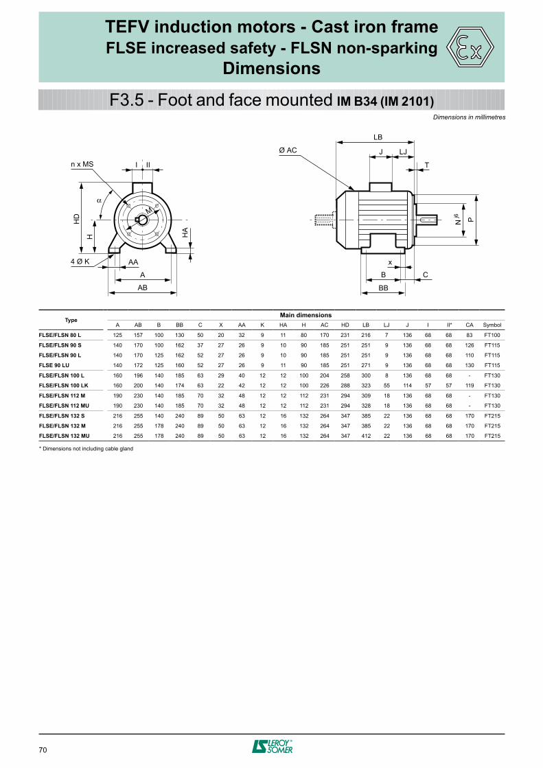
70
A
HD
H HA
AB
AA4 Ø K
I
M
n x MS II
J LJ
LB
T
N Pj6
Ø AC
x
B C
BB
α
TEFV induction motors - Cast iron frameFLSE increased safety - FLSN non-sparking
Dimensions
F3.5 - Foot and face mounted IM B34 (IM 2101)
TypeMain dimensions
A AB B BB C X AA K HA H AC HD LB LJ J I II* CA Symbol
FLSE/FLSN 80 L 125 157 100 130 50 20 32 9 11 80 170 231 216 7 136 68 68 83 FT100
FLSE/FLSN 90 S 140 170 100 162 37 27 26 9 10 90 185 251 251 9 136 68 68 126 FT115
FLSE/FLSN 90 L 140 170 125 162 52 27 26 9 10 90 185 251 251 9 136 68 68 110 FT115
FLSE 90 LU 140 172 125 160 52 27 26 9 11 90 185 251 271 9 136 68 68 130 FT115
FLSE/FLSN 100 L 160 196 140 185 63 29 40 12 12 100 204 258 300 8 136 68 68 - FT130
FLSE/FLSN 100 LK 160 200 140 174 63 22 42 12 12 100 226 288 323 55 114 57 57 119 FT130
FLSE/FLSN 112 M 190 230 140 185 70 32 48 12 12 112 231 294 309 18 136 68 68 - FT130
FLSE/FLSN 112 MU 190 230 140 185 70 32 48 12 12 112 231 294 328 18 136 68 68 - FT130
FLSE/FLSN 132 S 216 255 140 240 89 50 63 12 16 132 264 347 385 22 136 68 68 170 FT215
FLSE/FLSN 132 M 216 255 178 240 89 50 63 12 16 132 264 347 385 22 136 68 68 170 FT215
FLSE/FLSN 132 MU 216 255 178 240 89 50 63 12 16 132 264 347 412 22 136 68 68 170 FT215
* Dimensions not including cable gland
Dimensions in millimetres

71
J LJ
LB
T
N Pj6
Ø AC
HJ
I
AC
M
n x MS II
α = 45°
TEFV induction motors - Cast iron frameFLSE increased safety - FLSN non-sparking
Dimensions
F3.6 - Face mounted IM B14 (IM 3601)Dimensions in millimetres
IEC symbolFaceplate dimensions Main dimensions
M N P T n α° MS Type AC LB HJ LJ J I II*
FT 100 100 80 120 3 4 45 M6 FLSE/FLSN 80 L 170 216 152 7 136 68 68
FT 115 115 95 140 3 4 45 M8 FLSE/FLSN 90 S 185 251 158 9 136 68 68
FT 115 115 95 140 3 4 45 M8 FLSE/FLSN 90 L 185 251 158 9 136 68 68
FT 115 115 95 140 3 4 45 M8 FLSE 90 LU 185 271 158 9 136 68 68
FT 130 130 110 160 3.5 4 45 M8 FLSE/FLSN 100 L 204 300 158 8 136 68 68
FT 130 130 110 160 3.5 4 45 M8 FLSE/FLSN 100 LK 226 323 176 55 114 57 57
FT 130 130 110 160 3.5 4 45 M8 FLSE/FLSN 112 M 231 309 182 18 136 68 68
FT 130 130 110 160 3.5 4 45 M8 FLSE/FLSN 112 MU 231 328 182 18 136 68 68
FT 215 215 180 250 4 4 45 M12 FLSE/FLSN 132 S 264 385 205 22 136 68 68
FT 215 215 180 250 4 4 45 M12 FLSE/FLSN 132 M 264 385 205 22 136 68 68
FT 215 215 180 250 4 4 45 M12 FLSE/FLSN 132 MU 264 412 205 22 136 68 68
* Dimensions not including cable gland

72
3-phase TEFV induction motorsATEX GAS - Zones 1 & 2

73
TEFV induction motors - Aluminium frameLSE increased safety - LSN non-sparking
Electromechanical characteristicsPAGE
G1.1 - 2 poles - 3000 min–1 - Ex e II T3 ....................................................... 74
G1.2 - 4 poles - 1500 min–1 - Ex e II T3 ....................................................... 75
G1.3 - 6 poles - 1000 min–1 - Ex e II T3 ....................................................... 76
G1.4 - 2 poles - 3000 min–1 - Ex e II T4 ....................................................... 77
G1.5 - 4 poles - 1500 min–1 - Ex e II T4 ....................................................... 78
G2.1 - 2 poles - 3000 min–1 - Ex nA II T3 .................................................... 80
G2.2 - 4 poles - 1500 min–1 - Ex nA II T3 .................................................... 81
G2.3 - 6 poles - 1000 min–1 - Ex nA II T3 .................................................... 82
G2.4 - 8 poles - 750 min–1 - Ex nA II T3 ...................................................... 83
G3.1 - Shaft extensions ............................................................................. 84
G3.2 - Foot mounted IM B3 (IM 1001) ............................................................ 85
G3.3 - Foot and flange mounted IM B35 (IM 2001) ......................................... 86
G3.4 - Flange mounted IM B5 (IM 3001) ........................................................ 87
G3.5 - Foot and face mounted IM B34 (IM 2101) ............................................ 88
G3.6 - Face mounted IM B14 (IM 3601) .......................................................... 89
G1 - Selection data - LSE increased safety - Zone 1
G2 - Selection data - LSN non-sparking - Zone 2
G3 - Dimensions

74
TEFV induction motors - Aluminium frameLSE increased safety - Zone 1
Selection data
G1.1 - 2 poles - 3000 min-1
MAINS SUPPLY D 230 / Υ 400 V or D 400 V 50 Hz
Type
Rated power
Rated speed
Rated torque
Rated current
Power factor
Efficiency IEC 60034-2; 1996
Starting current/ Rated current
Starting torque/ Rated torque
Maximum torque/ Rated torque
Locked rotor time
Moment of inertia Weight Noise
PN NN MN IN (400V) Cos φ η Id/In Md/Mn MM/Mn tE J IM B3 LP
kW min-1 N.m A % s kg.m2 kg db(A)
LSE 80 L 0.75 2872 2.5 1.6 0.84 79.4 6.8 2.9 3.0 7.6 0.0009 9.7 61
LSE 80 L 1.1 2870 3.75 2.3 0.86 78.5 7.9 3.2 3.1 7.5 0.0011 11.3 61
LSE 90 L 1.5 2860 5 2.9 0.88 83.6 7.8 3.1 3.1 7 0.0017 14 64
LSE 90 L 2.2 2884 7.5 4.2 0.87 85.7 8.5 2.4 3.1 6 0.0022 17.8 64
LSE 100 L 3 2887 10.1 5.6 0.89 86.2 9.9 2.3 2.3 6 0.0029 24 66
LES 112 MU 4 2928 13.5 7.1 0.92 88.6 9.6 2.0 3.0 7 0.0088 39 66
LSE 132 SM 5.5 2926 18.6 9.7 0.91 89.8 7.7 1.7 2.6 8.6 0.016 49 72
LSE 132 SM 7.5 2929 25.4 13.1 0.92 90.4 8.5 1.7 2.6 8.5 0.018 54 72
LSE 160 MP 11 2935 36 19.1 0.92 90.5 9.8 1.7 2.6 6 0.023 72 72
LSE 160 L 15 2933 48.8 26.7 0.89 91 7.8 2.6 3.1 5 0.044 88 72
LSE 180 MT 18.5 2939 60.1 32.7 0.89 91.7 8.3 2.8 3.1 7 0.052 99 72
LSE 200 LT 22 2946 71.3 36.8 0.92 93.7 8.5 2.6 3.3 9 0.089 154 73
LSE 200 L 30 2956 96.9 50.9 0.91 93.5 7.8 2.7 3.1 7 0.12 180 73
LSE 225MT 37 2951 120 62.7 0.91 93.6 7.8 2.7 3.1 6 0.14 200 73
LSE 250 MZ 45 2959 145 76.8 0.9 94 8.5 3.1 3.4 8 0.173 235 78
LSE 280 SC 55 2970 177 92 0.91 94.8 8.5 2.7 3.3 12 0.39 330 79
LSE 280 SC 75 2968 241 129 0.90 94.4 8.5 2.6 3.4 8 0.39 330 79
LSE 280 MC 90 2968 290 154 0.90 94.7 8.4 2.6 3.3 10 0.47 375 79
2 poles3000 min-1
Ex e II T3IP 55Cl. F - DT 80K400 V ± 10%

75
TEFV induction motors - Aluminium frameLSE increased safety - Zone 1
Selection data
G1.2 - 4 poles - 1500 min-1
MAINS SUPPLY D 230 / Υ 400 V or D 400 V 50 Hz
Type
Rated power
Rated speed
Rated torque
Rated current
Power factor
Efficiency IEC 60034-2; 1996
Starting current/ Rated current
Starting torque/ Rated torque
Maximum torque/ Rated torque
Locked rotor time
Moment of inertia Weight Noise
PN NN MN IN (400V) Cos φ η Id/In Md/Mn MM/Mn tE J IM B3 LP
kW min-1 N.m A % s kg.m2 kg db(A)
LSE 80 L 0.75 1430 5 2 0.72 74 5.3 2.2 2.3 10 0.0024 10.9 47
LSE 90 L 1.1 1440 7.5 2.5 0.83 78.8 6.0 2.2 2.6 8.1 0.0032 13.5 48
LSE 90 L 1.5 1450 10 3.7 0.75 78 6.2 1.7 2.0 7.2 0.0032 13.5 48
LSE 100 L 2.2 1444 15 4.5 0.85 83.5 6.5 2.1 2.2 7.5 0.0055 22.5 48
LSE 100 L 3 1423 20 6.2 0.85 83 6.8 2.0 2.1 7 0.0055 22.5 48
LSE 112 MU 4 1458 27.2 7.7 0.86 86.9 7.6 2.0 2.1 8.4 0.014 36.5 49
LSE 132 SM 5.5 1464 37.4 10.3 0.87 88.4 7.9 1.8 2.5 9 0.019 54.7 62
LSE 132 M 7.5 1457 50 14.8 0.85 86 7.9 1.9 2.6 5.5 0.023 59.9 62
LSE 160 MR 11 1468 74.7 22 0.82 89 9.8 2.4 3.1 5 0.035 78 62
LSE 160 L 15 1460 98.5 28.2 0.85 90.3 7.8 2.8 3.3 7 0.085 100 62
LSE 180 MR 18.5 1456 121 33.7 0.87 91.2 8.3 3.0 3.4 6 0.096 112 64
LSE 180 LU 22 1464 144 39.7 0.87 91.9 7.1 3.0 3.0 6 0.151 165 64
LSE 200 L 30 1472 195 54.8 0.85 93 6.6 2.7 2.6 6 0.24 205 64
LSE 225 SR 37 1471 240 68.2 0.84 93.2 6.6 3.0 2.9 12 0.29 235 64
LSE 250 ME 45 1480 290 81.3 0.85 94 7.3 2.7 2.6 12 0.63 320 66
LSE 250 ME 55 1478 355 102 0.84 93.6 7.0 2.7 2.8 10 0.63 320 66
LSE 280 SC 56 1478 485 138 0.84 94.2 7.2 2.8 2.9 6 0.83 380 69
LSE 280 MD 90 1479 581 162 0.85 95 8.0 3.2 3.0 8 1.03 450 69
4poles1500 min-1
Ex e II T3IP 55Cl. F - DT 80K400 V ± 10%

76
TEFV induction motors - Aluminium frameLSE increased safety - Zone 1
Selection data
G1.3 - 6 poles - 1000 min-1
MAINS SUPPLY D 230 / Υ 400 V or D 400 V 50 Hz
Type
Rated power
Rated speed
Rated torque
Rated current
Power factor
Efficiency IEC 60034-2; 1996
Starting current/ Rated current
Starting torque/ Rated torque
Maximum torque/ Rated torque
Locked rotor time
Moment of inertia Weight Noise
PN NN MN IN (400V) Cos φ η Id/In Md/Mn MM/Mn tE J IM B3 LP
kW min-1 N.m A % s kg.m2 kg db(A)
LSE 80 L 0.37 948 3.7 1.2 0.68 65.3 3.7 1.6 2.0 12 0.0032 9.7 41
LSE 80 L 0.55 955 5.5 1.8 0.64 68.6 4.5 2.1 2.4 8.4 0.0042 11 41
LSE 90 L 0.75 935 7.5 2.2 0.67 75 4.6 2.6 2.6 10.5 0.0039 13.5 51
LSE 90 LU 1.1 915 11.5 2.9 0.79 72.8 5.6 2.8 2.9 9 0.0051 17 51
LSE 100 L 1.5 928 15 4.2 0.67 76.8 5.0 2.7 2.7 8.5 0.0069 20 50
LSE 112 M 2.2 960 22.7 5.3 0.76 81 6.2 2.2 2.7 7.3 0.0087 24.2 51
LSE 132 SM 3 963 30 7 0.74 84.6 4.3 1.2 1.6 6.9 0.026 43.4 55
LSE 132 M 4 966 40 9.1 0.74 85.9 4.6 1.3 1.6 7.1 0.034 59.4 55
LSE 132 MU 5.5 963 55 12.3 0.75 86.4 4.7 1.4 1.6 7.1 0.043 66.5 55
LSE 160 M 7.5 965 74.2 15.9 0.79 86 5.0 1.7 2.4 12 0.084 81 56
LSE 160 L 11 963 109 23.6 0.78 86.2 6.0 1.8 2.5 12 0.126 105 56
LSE 180 L 15 971 140 30.6 0.8 88.5 6.4 2.4 2.7 6 0.191 135 60
LSE 200 LT 18.5 972 172 38.9 0.77 89.2 6.5 2.5 2.8 6 0.237 160 62
LSE 200 L 22 974 216 44.1 0.8 90.1 6.2 2.0 2.7 10 0.287 190 62
LSE 225 MR 30 976 294 61.9 0.77 90.8 6.7 2.7 3.0 8 0.38 235 63
LSE 250 ME 37 978 361 71.1 0.81 68.0 6.2 2.3 2.5 12 0.85 305 65
LSE 280 SC 45 978 439 86.5 0.81 68.0 6.2 2.3 2.5 12 0.99 340 65
LSE 280 MC 55 978 537 106 0.81 68.0 6.0 2.4 2.5 12 1.19 385 65
6poles1000 min-1
Ex e II T3IP 55Cl. F - DT 80K400 V ± 10%

77
TEFV induction motors - Aluminium frameLSE increased safety - Zone 1
Selection data
G1.4 - 2 poles - 3000 min-1
MAINS SUPPLY D 230 / Υ 400 V or D 400 V 50 Hz
Type
Rated power
Rated speed
Rated torque
Rated current
Power factor
Efficiency IEC 60034-2; 1996
Starting current/ Rated current
Starting torque/ Rated torque
Maximum torque/ Rated torque
Locked rotor time
Moment of inertia Weight Noise
PN NN MN IN (400V) Cos φ η Id/In Md/Mn MM/Mn tE J IM B3 LP
kW min-1 N.m A % s kg.m2 kg db(A)
LSE 80 L 0.75 2879 2.5 1.5 0.84 83.2 7.3 2.5 3.0 5 0.0011 11.3 61
LSE 90 L 1.1 2865 3.7 2.1 0.91 83.9 7.6 2.1 2.7 5 0.0021 16 64
LSE 90 L 1.5 2865 5 2.9 0.92 84 8.6 3.2 3.1 5 0.0021 16 64
LSE 100 L 2.2 2850 7.4 4.2 0.93 84.5 8.8 2.8 3.4 5 0.0029 24 66
LSE 112 MU 3 2924 10.1 5.3 0.94 86.7 9.1 2.7 3.4 5 0.0088 39 66
LES 132 SM 4 2944 13.5 7.5 0.87 88.4 9.7 2.1 3.2 5 0.016 49 72
LSE 132 SM 5.5 2953 18.6 9.7 0.92 89.5 8.9 1.7 2.7 5 0.018 54 72
LSE 160 MP 7.5 2933 25.4 12.9 0.94 89.9 5.9 1.4 2.2 7.3 0.023 68 72
2 poles3000 min-1
Ex e II T4IP 55Cl. F - DT 80K400 V ± 10%

78
TEFV induction motors - Aluminium frameLSE increased safety - Zone 1
Selection data
G1.5 - 4 poles - 1500 min-1
MAINS SUPPLY D 230 / Υ 400 V or D 400 V 50 Hz
Type
Rated power
Rated speed
Rated torque
Rated current
Power factor
Efficiency IEC 60034-2; 1996
Starting current/ Rated current
Starting torque/ Rated torque
Maximum torque/ Rated torque
Locked rotor time
Moment of inertia Weight Noise
PN NN MN IN (400V) Cos φ η Id/In Md/Mn MM/Mn tE J IM B3 LP
kW min-1 N.m A % s kg.m2 kg db(A)
LSE 80 L 0.55 1425 3.75 1.4 0.76 75 5.2 1.9 2.2 9 0.0024 10.9 47
LSE 90 L 0.75 1450 5 1.7 0.81 80.5 6.5 2.0 2.7 6 0.0032 13.5 48
LSE 90 L 1.1 1447 7.5 2.5 0.78 82.1 6.7 1.8 2.3 5.5 0.0037 15.2 48
LSE 100 L 1.5 1442 10 3.3 0.8 82.8 6.3 1.8 2.2 6 0.0064 25.5 48
LSE 100 LG 2.2 1466 15 4.4 0.84 87.3 7.3 1.8 2.2 5 0.0109 30.5 48
LSE 112 MU 3 1464 20 5.9 0.85 87.8 7.6 2.0 2.2 5 0.014 36.5 49
LSE 132 SM 4 1465 27.5 7.4 0.89 88 7.7 1.8 2.6 5 0.019 54.7 62
LSE 132 SM 5.5 1466 37.5 10.4 0.87 89.1 8.1 2.0 2.7 5 0.023 59.9 62
LSE 132 MU 7.5 1461 50 13.8 0.88 89.2 7.4 1.6 2.3 5 0.0306 65.5 62
4poles1500 min-1
Ex e II T4IP 55Cl. F - DT 80K400 V ± 10%

79
TEFV induction motors - Aluminium frameLSE increased safety - Zone 1
Selection data

80
TEFV induction motors - Aluminium frameLSN non-sparking - Zone 2
Selection data
G2.1 - 2 poles - 3000 min-1
MAINS SUPPLY D 230 / Υ 400 V or D 400 V 50 Hz
Type
Rated power
Rated speed
Rated torque
Rated current
Power factor
Efficiency IEC 60034-2; 1996
Starting current/ Rated current
Starting torque/ Rated torque
Maximum torque/ Rated torque
Moment of inertia Weight Noise
PN NN MN IN (400V) Cos φ η Id/In Md/Mn MM/Mn J IM B3 LP
kW min-1 N.m A 4/4 3/4 2/4 4/4 3/4 2/4 kg.m2 kg db(A)
LSN 80 L 0.75 2840 2.5 1.64 0.87 0.8 0.68 76 76.5 74 5.9 2.4 2.2 0.0007 8.2 61
LSN 80 L 1.1 2837 3.7 2.4 0.84 0.77 0.65 78 78.5 76.6 5.8 2.7 2.4 0.0009 9.7 61
LSN 80 L 1.5 2859 5.01 3.2 0.83 0.76 0.62 80.3 80.4 78 7.0 3.2 2.8 0.0011 11.3 61
LSN 90 S 1.5 2870 4.99 3.4 0.81 0.72 0.58 79.6 78.9 75.1 8.0 3.9 4.0 0.0014 12 64
LSN 90 L 1.8 2865 6 3.6 0.86 0.8 0.69 83.1 83.4 81.7 8.0 3.6 3.6 0.0017 14 64
LSN 90 L 2.2 2862 7.34 4.3 0.88 0.83 0.73 83.6 84 82.9 7.7 3.7 3.3 0.0021 16 64
LSN 100 L 3 2868 9.99 6.3 0.81 0.73 0.59 83.9 83.8 80.8 7.5 3.8 3.9 0.0022 20 66
LSN 112 M 4 2877 13.3 7.9 0.85 0.78 0.65 86 86.1 84.4 7.8 2.9 2.9 0.0029 24.4 66
LSN 112 MG 5.5 2916 18 10.5 0.88 0.81 0.71 86.6 87.2 85.6 9.0 3.1 3.5 0.0076 33 66
LSN 132 S 5.5 2916 18 10.5 0.88 0.81 0.71 86.6 87.2 85.6 9.0 3.1 3.5 0.0076 34.4 72
LSN 132 S 7.5 2905 24.5 14.7 0.85 0.78 0.63 86.5 86.4 84.5 8.7 3.4 3.6 0.0088 39 72
LSN 132 M 9 2910 29.5 17.3 0.85 0.8 0.71 88.1 88.4 87.5 8.6 2.5 3.5 0.016 49 72
LSN 132 M 11 2944 35.7 20.7 0.86 0.81 0.69 89.4 89.4 87.7 7.5 2.7 3.4 0.018 54 72
LSN 160 MP 11 2944 35.7 20.7 0.86 0.81 0.69 89.4 89.4 87.7 7.5 2.7 3.4 0.019 62 72
LSN 160 MP 15 2935 48.8 28.4 0.85 0.79 0.71 90 90.1 85.1 8.1 3.0 3.5 0.023 72 72
LSN 160 L 18.5 2934 60.2 33.7 0.87 0.83 0.75 91 91.2 90.4 8.0 3.0 3.3 0.044 88 72
LSN 180 MT 22 2938 71.5 39.9 0.87 0.84 0.76 91.5 91.8 91.2 8.1 3.1 3.1 0.052 99 72
LSN 200 LT 30 2946 97.2 52.1 0.9 0.87 0.82 92.4 92.7 92.1 8.6 2.7 3.4 0.089 154 73
LSN 200 L 37 2950 120 64.6 0.89 0.87 0.82 92.9 93 92.2 7.4 2.6 3.0 0.12 180 73
LSN 225 MT 45 2950 146 78 0.9 0.87 0.82 93.3 93.4 93.1 7.5 2.8 3.1 0.14 200 73
LSN 250 MZ 55 2956 178 95.2 0.89 0.86 0.8 93.7 93.7 93.1 8.3 3.1 3.4 0.173 235 78
LSN 280 SC 75 2968 241 127 0.9 0.87 0.82 94.4 94.4 93.8 8.5 2.6 3.4 0.39 330 79
LSN 280 MC 90 2968 290 152 0.9 0.88 0.83 94.7 94.7 94.1 8.4 2.6 3.3 0.47 375 79
2 poles3000 min-1
Ex nA II T3IP 55Cl. F - DT 80K400 V ± 10%

81
TEFV induction motors - Aluminium frameLSN non-sparking - Zone 2
Selection data
G2.2 - 4 poles - 1500 min-1
MAINS SUPPLY D 230 / Υ 400 V or D 400 V 50 Hz
Type
Rated power
Rated speed
Rated torque
Rated current
Power factor
Efficiency IEC 60034-2; 1996
Starting current/ Rated current
Starting torque/ Rated torque
Maximum torque/ Rated torque
Moment of inertia Weight Noise
PN NN MN IN (400V) Cos φ η Id/In Md/Mn MM/Mn J IM B3 LP
kW min-1 N.m A 4/4 3/4 2/4 4/4 3/4 2/4 kg.m2 kg db(A)
LSN 80 L 0.55 1410 3.72 1.42 0.76 0.68 0.55 73.4 69.3 62 4.5 2.0 2.3 0.0013 8.2 47
LSN 80 L 0.75 1400 5.12 2.01 0.77 0.71 0.59 70 70 66 4.5 2.0 2.2 0.0018 9.3 47
LSN 80 L 0.9 1425 6.03 2.44 0.73 0.67 0.54 73 73 70 5.8 3.0 3.0 0.0024 10.9 47
LSN 90 S 1.1 1429 7.35 2.5 0.84 0.77 0.64 76.8 78.4 77.1 4.8 1.6 2.0 0.0026 11.5 48
LSN 90 L 1.5 1428 10 3.4 0.82 0.74 0.6 78.5 79.4 77.5 5.3 1.8 2.3 0.0032 13.5 48
LSN 90 L 1.8 1438 12 4 0.82 0.75 0.61 80.1 80.8 79 6.0 2.1 3.2 0.0037 15.2 48
LSN 100 L 2.2 1436 14.6 4.8 0.81 0.73 0.59 81 81.5 79.8 5.9 2.1 2.5 0.0043 20 48
LSN 100 L 3 1437 19.9 6.5 0.81 0.72 0.59 82.6 82.6 80.8 6.0 2.5 2.8 0.0055 22.5 48
LSN 112 M 4 1438 26.6 8.3 0.83 0.76 0.57 84.2 84.2 83.4 7.1 2.5 3.0 0.0067 24.9 49
LSN 132 S 5.5 1447 36.7 11.1 0.83 0.79 0.67 85.7 86.4 85.8 6.3 2.4 2.8 0.014 36.5 62
LSN 132 M 7.5 1451 49.4 15.2 0.82 0.74 0.61 87 86.4 84.9 7.0 2.4 2.9 0.019 54.7 62
LSN 132 M 9 1455 59.1 18.1 0.82 0.74 0.62 87.7 87.6 86.2 6.9 2.2 3.1 0.023 59.9 62
LSN 160 MP 11 1454 72.2 21 0.86 0.79 0.67 88.4 88.6 87.4 7.7 2.3 3.2 0.03 70 62
LSN 160 LR 15 1453 98.6 28.8 0.84 0.78 0.69 89.4 89.8 88.4 7.5 2.9 3.6 0.036 86 62
LSN 180 MT 18.5 1456 121 35.2 0.84 0.79 0.67 90.3 90.8 90.3 7.6 2.7 3.2 0.085 100 64
LSN 180 LR 22 1456 144 41.7 0.84 0.79 0.68 90.7 91.2 90.9 7.9 3.0 3.3 0.096 112 64
LSN 200 LT 30 1460 196 56.3 0.84 0.8 0.69 91.5 92 91.5 6.6 2.9 2.9 0.151 165 64
LSN 225 ST 37 1468 241 68.7 0.84 0.8 0.7 92.5 93.1 92.9 6.3 2.7 2.6 0.24 205 64
LSN 225 MR 45 1468 293 83.3 0.84 0.8 0.7 92.8 93.3 93 6.3 2.7 2.6 0.29 235 64
LSN 250 ME 55 1478 355 101 0.84 0.8 0.71 93.6 93.8 93.2 7.0 2.7 2.8 0.63 320 66
LSN 280 SC 75 1478 485 137 0.84 0.8 0.71 94.2 94.4 93.8 7.2 2.8 2.9 0.83 380 69
LSN 280 MD 90 1478 582 164 0.84 0.8 0.71 94.4 94.5 93.8 7.6 3.0 3.0 1.03 450 69
4poles1500 min-1
Ex nA II T3IP 55Cl. F - DT 80K400 V ± 10%

82
TEFV induction motors - Aluminium frameLSN non-sparking - Zone 2
Selection data
G2.3 - 6 poles - 1000 min-1
MAINS SUPPLY D 230 / Υ 400 V or D 400 V 50 Hz
Type
Rated power
Rated speed
Rated torque
Rated current
Power factor
Efficiency IEC 60034-2; 1996
Starting current/ Rated current
Starting torque/ Rated torque
Maximum torque/ Rated torque
Moment of inertia Weight Noise
PN NN MN IN (400V) Cos φ η Id/In Md/Mn MM/Mn J IM B3 LP
kW min-1 N.m A 4/4 3/4 2/4 4/4 3/4 2/4 kg.m2 kg db(A)
LSN 80 L 0.25 955 2.5 0.85 0.67 0.64 0.48 63.1 63 56 3.9 1.6 1.8 0.0024 8.4 41
LSN 80 L 0.37 950 3.72 1.1 0.72 0.67 0.57 66 61 59 4.3 1.7 2.2 0.0032 9.7 41
LSN 80 L 0.55 950 5.53 1.8 0.64 0.6 0.47 68 63 55 4.9 2.1 2.6 0.0042 11 41
LSN 90 S 0.75 930 7.7 2.1 0.77 0.66 0.54 68.5 65 60 4.2 2.4 2.6 0.0039 13.5 51
LSN 90 L** 1.1 915 11.5 3 0.76 0.67 0.55 70 70 66 4.7 2.4 2.5 0.0048 15.2 51
LSN 100 L** 1.5 905 15.8 4.2 0.74 0.62 0.52 69 69 65 4.5 2.5 2.7 0.0058 20 50
LSN 112 M** 2.2 905 23.2 5.8 0.76 0.66 0.53 72 72 68 5.6 2.8 2.7 0.0087 24.2 51
LSN 132 M** 3 957 30.3 6.8 0.75 0.66 0.53 81.1 78 75 6.0 2.0 2.6 0.018 38.3 51
LSN 132 M 4 961 39.7 9.3 0.75 0.66 0.56 83.6 83 78 5.9 2.5 2.9 0.034 53.3 55
LSN 132 M** 5.5 960 54.7 13.3 0.71 0.65 0.52 84.1 83.5 80 5.5 2.5 2.8 0.039 59.4 55
LSN 160 M 7.5 969 73.9 16.3 0.79 0.74 0.63 85.2 84.8 82.6 5.2 1.7 2.5 0.089 77 56
LSN 160 L 11 968 109 23.4 0.78 0.71 0.64 86.3 86.5 85 5.3 1.8 2.6 0.105 85 56
LSN 180 L 15 972 147 30.1 0.81 0.76 0.65 87.1 87.3 86.1 6.8 2.3 2.8 0.192 135 60
LSN 200 LT 18.5 970 182 37 0.81 0.76 0.65 89 89.3 88.1 6.4 2.4 2.8 0.236 160 62
LSN 200 L 22 972 216 43.6 0.81 0.76 0.65 89.9 90.1 89 6.0 2.0 2.7 0.295 190 62
LSN 225 MR 30 968 296 59.5 0.81 0.79 0.72 89.9 90.3 89.2 6.0 2.2 2.5 0.39 235 63
LSN 250 ME 37 978 361 71.1 0.81 0.79 0.69 92.7 93.2 92.9 6.2 2.3 2.5 0.85 305 65
LSN 280 SC 45 978 439 86.5 0.81 0.79 0.69 92.7 93.2 92.9 6.2 2.3 2.5 0.99 340 65
LSN 280 MC 55 978 537 106 0.81 0.79 0.72 92.6 93.3 93.1 6.0 2.4 2.5 1.19 385 65
6poles1000 min-1
Ex nA II T3IP 55Cl. F - DT 80K400 V ± 10%

83
TEFV induction motors - Aluminium frameLSN non-sparking - Zone 2
Selection data
G2.4 - 8 poles - 750 min-1
MAINS SUPPLY D 230 / Υ 400 V or D 400 V 50 Hz
Type
Rated power
Rated speed
Rated torque
Rated current
Power factor
Efficiency IEC 60034-2; 1996
Starting current/ Rated current
Starting torque/ Rated torque
Maximum torque/ Rated torque
Moment of inertia Weight Noise
PN NN MN IN (400V) Cos φ η Id/In Md/Mn MM/Mn J IM B3 LP
kW min-1 N.m A 4/4 3/4 2/4 4/4 3/4 2/4 kg.m2 kg db(A)
LSN 80 L 0.18 705 2.44 0.79 0.63 0.54 0.45 52 48 43 2.9 1.5 1.9 0.0031 9.7 41
LSN 80 L 0.25 700 3.41 0.98 0.68 0.6 0.51 54 52 45 2.8 1.7 1.9 0.0041 11.3 41
LSN 90 L 0.37 685 5.16 1.2 0.72 0.63 0.52 62 62 56 3.8 1.7 1.8 0.0038 13.5 43
LSN 90 S 0.37 685 5.16 1.2 0.72 0.63 0.52 62 62 56 3.8 1.7 1.8 0.0038 13.5 43
LSN 90 L 0.55 670 7.84 1.7 0.72 0.61 0.52 63.5 62 59 3.5 1.7 1.7 0.0047 15.2 43
LSN 100 L 0.75 670 10.7 2.4 0.71 0.58 0.47 63.5 61.5 55 3.5 1.8 2.2 0.0047 18 43
LSN 100 L 1.1 670 15.7 3.7 0.68 0.6 0.49 63 62.5 58 3.7 2.0 2.2 0.0068 21.8 43
LSN 112 MG 1.5 710 20.2 4.7 0.64 0.55 0.43 72 69 62.5 3.8 2.0 2.1 0.015 24 49
LSN 132 SM 2.2 713 29.5 6.1 0.68 0.56 0.45 77.1 77.5 71 4.0 1.7 2.0 0.025 45.6 54
LSN 132 M 3 712 40.2 8 0.65 0.56 0.45 79.8 82.9 79 4.3 1.9 2.2 0.033 53.9 54
LSN 160 M 4 718 53.2 11 0.63 0.55 0.43 83.3 83.4 81.3 3.9 1.7 2.3 0.068 84 66
LSN 160 M 5.5 716 73.4 15.1 0.63 0.55 0.43 83.3 83.5 81.8 3.9 1.7 2.3 0.071 89 66
LSN 160 L 7.5 714 100 20.6 0.63 0.55 0.43 83.4 84 82.6 3.9 1.9 2.3 0.09 101 66
LSN 180 L 11 720 146 25.6 0.72 0.68 0.57 86 86.3 84.2 3.8 1.4 1.9 0.205 140 68
LSN 200 L 15 725 198 32.9 0.75 0.7 0.57 87.7 87.9 86.3 4.4 1.6 2.1 0.27 185 65
LSN 225 ST 18.5 725 244 42.4 0.72 0.66 0.54 87.5 87.7 86.2 4.2 1.6 2.1 0.33 210 65
LSN 225 MR 22 725 290 51.9 0.7 0.63 0.51 87.4 87.2 85.1 4.4 1.9 2.3 0.4 240 65
LSN 250 ME 30 730 392 60.3 0.79 0.73 0.63 90.9 91.2 90.1 5.8 1.9 2.7 0.99 330 65
LSN 280 SC 37 730 484 74.3 0.79 0.73 0.63 91 91.4 90.7 5.6 1.8 2.6 1.19 370 65
LSN 280 MD 45 728 590 91.4 0.78 0.73 0.63 91.1 91.7 91.1 5.4 1.8 2.6 1.39 430 65
8poles750 min-1
Ex nA II T3IP 55Cl. F - DT 80K400 V ± 10%

84
E
D
M.O x p
EA
DA
MOA x pA
F
GD G
FA
GF GB
TEFV induction motors - Aluminium frameLSE increased safety - LSN non-sparking
Dimensions
G3.1 - Shaft extensions
Type
Main shaft extensions4, 6 and 8 poles 2 poles
F GD D G E O p L LO F GD D G E O p L LO
LSE/LSN 80 L 6 6 19j6 15.5 40 6 16 30 6 0 6 6 19j6 15.5 40 6 16 30 6
LSE/LSN 90 S/L 8 7 24j6 20 50 8 19 40 6 0 8 7 24j6 20 50 8 19 40 6
LSE/LSN 100 L 8 7 28j6 24 60 10 22 50 6 0 8 7 28j6 24 60 10 22 50 6
LSE/LSN 112 M/MG/MU 8 7 28j6 24 60 10 22 50 6 0 8 7 28j6 24 60 10 22 50 6
LSE/LSN 132 S/SM/M 10 8 38k6 33 80 12 28 63 10 0 10 8 38k6 33 80 12 28 63 10
LSE/LSN 160 M/MP/MR/L/LR 12 8 42k6 37 110 16 36 100 6 0 12 8 42k6 37 110 16 36 100 6
LSE/LSN 180 MR/MT/L/LR/LU 14 9 48k6 42.5 110 16 36 98 12 0 14 9 48k6 42.5 110 16 36 98 12
LSE/LSN 200 L/LT 16 10 55m6 49 110 20 42 97 13 0 16 10 55m6 49 110 20 42 97 13
LSE/LSN 225 SR/ST/MG/MR/MT 18 11 60m6 53 140 20 42 126 14 0 16 10 55m6 49 110 20 42 97 13
LSE/LSN 250 ME/MF/MZ 18 11 65m6 58 140 20 42 126 14 0 18 11 60m6 53 140 20 42 126 14
LSE/LSN 280 SC/SD/MC/MD 20 12 75m6 67.5 140 20 42 125 15 0 18 11 65m6 58 140 20 42 125 14
Type
Secondary shaft extensions4, 6 and 8 poles 2 poles
FA GF DA GB EA OA pA L’ LO’ FA GF DA GB EA OA pA L’ LO’
LSE/LSN 80 L 5 5 14j6 11 30 5 15 25 3.5 0 5 5 14j6 11 30 5 15 25 3.5
LSE/LSN 90 S/SL/L/LU 6 6 19j6 15.5 40 6 16 30 6 0 6 6 19j6 15.5 40 6 16 30 6
LSE/LSN 100 L 8 7 24j6 20 50 8 19 40 6 0 8 7 24j6 20 50 8 19 40 6
LSE/LSN 112 M/MG/MU 8 7 24j6 20 50 8 19 40 6 0 8 7 24j6 20 50 8 19 40 6
LSE/LSN 132 S/SM/M 8 7 28k6 24 60 10 22 50 6 0 8 7 28k6 24 60 10 22 50 6
LSE/LSN 160 M/MP/MR/L/LR/LU 12 8 38k6 37 80 16 36 100 6 0 12 8 38k6 37 80 16 36 100 6
LSE/LSN 180 MR/MT/L/LR/LU 14 9 48k6 42.5 110 16 36 98 12 0 14 9 48k6 42.5 110 16 36 98 12
LSE/LSN 200 L/LT/LU 16 10 55m6 49 110 20 42 97 13 0 16 10 55m6 49 110 20 42 97 13
LSE/LSN 225 SR/ST/MG/MR/MT 18 11 60m6 53 140 20 42 126 14 0 16 10 55m6 49 110 20 42 97 13
LSE/LSN 250 ME/MF/MZ 18 11 60m6 53 140 20 42 126 14 0 18 11 60m6 53 140 20 42 126 14
LSE/LSN 280 SC/SD/MC/MD 18 11 65m6 58 140 20 42 126 14 0 18 11 65m6 58 140 20 42 126 14
Dimensions in millimetres

85
J LJ
LB
Ø AC
x
B C
BB
CAA
HD
H HA
AB
AA4 Ø K
I II
TEFV induction motors - Aluminium frameLSE increased safety - LSN non-sparking
Dimensions
G3.2 - Foot mounted IM B3 (IM 1001)Dimensions in millimetres
TypeMain dimensions
A AB B BB C X AA K HA H AC HD LB LJ J I II* CA
LSE/LSN 80 L 125 157 100 120 50 10 29 9 10 80 170 227 215 7 124 62 62 68
LSE/LSN 90 S 140 172 100 120 56 10 37 10 11 90 190 247 218 7 124 62 62 66
LSE/LSN 90 SL/L 140 172 125 162 56 28 37 10 11 90 190 247 245 7 124 62 62 68
LSE/LSN 100 L 160 196 140 165 63 12 40 12 13 100 200 262 290 7 124 62 62 93
LSE/LSN 112 M 190 220 140 165 70 12 45 12 14 112 200 274 290 16 124 62 62 86
LSE/LSN 112 MG 190 220 140 165 70 12 52 12 14 112 235 284 315 16 124 62 62 110
LSE/LSN 112 MU 190 220 140 165 70 12 52 12 14 112 235 284 334 16 124 62 62 130
LSE/LSN 132 S 216 250 140 170 89 16 50 12 15 132 235 304 350 33 124 62 62 128
LSE/LSN 132 SM/M 216 250 178 208 89 16 59 12 18 132 280 331 387 17 124 62 62 126
LSE/LSN 132 MU 216 250 178 208 89 16 59 12 18 132 280 331 410 17 124 62 62 148
LSE/LSN 160 MP 254 294 210 294 108 20 64 14.5 25 160 315 361 468 48.5 124 62 62 154
LSE/LSN 160 M 254 294 210 294 108 20 60 14.5 25 160 316 409 495 54.8 205 115 98 182
LSE/LSN 160 LR 254 294 254 294 108 20 64 14.5 25 160 315 361 495 48.5 124 62 62 138
LSE/LSN 160 MR 254 294 210 294 108 20 64 14.5 25 160 316 361 495 48.5 124 62 62 138
LSE/LSN 160 L 254 294 254 294 108 20 60 14.5 25 160 316 409 495 54.8 205 115 98 138
LSE/LSN 180 MT 279 324 241 316 121 20 79 14.5 28 180 316 453 495 39.2 217 103 145 138
LSE/LSN 180 MR 279 324 241 316 121 20 79 14.5 28 180 316 453 520 39.2 217 103 145 163
LSE/LSN 180 LR 279 324 279 316 121 20 79 14.5 28 180 316 460 520 39.2 217 103 145 125
LSE/LSN 180 L 279 339 279 329 121 25 86 14.5 25 180 350 460 552 48 217 103 145 159
LSE/LSN 180 LU 279 339 279 329 121 25 86 14.5 25 180 350 460 593 48 217 103 145 199
LSE/LSN 200 LT 318 378 305 365 133 30 108 18.5 30 200 350 480 599 54 217 103 145 167
LSE/LSN 200 L 318 388 305 375 133 35 103 18.5 36 200 390 505 621 62 217 103 145 194
LSE/LSN 225 ST 356 431 286 386 149 50 127 18.5 36 225 390 525 627 68 217 103 145 203
LSE/LSN 225 SR 356 431 286 386 149 50 127 18.5 36 225 390 525 676 68 217 103 145 253
LSE/LSN 225 MT 356 431 311 386 149 50 127 18.5 36 225 390 525 627 68 217 103 145 178
LSE/LSN 225 MR 356 431 311 386 149 50 127 18.5 36 225 390 525 676 68 217 103 145 228
LSE/LSN 225 MG 356 420 311 375 149 30 65 18.5 30 225 479 629 810 68 292 148 180 360
LSE/LSN 250 MZ 406 470 349 449 168 70 150 24 47 250 390 550 676 68 217 103 145 171
LSE/LSN 250 ME 406 470 349 420 168 35 90 24 36 250 479 655 810 68 292 148 180 303
LSE/LSN 250 MF 406 470 349 420 168 35 90 24 36 250 479 655 870 68 292 148 180 363
LSE/LSN 280 SC 457 520 368 478 190 35 90 24 35 280 479 685 810 68 292 148 180 262
LSE/LSN 280 SD 457 520 368 478 190 35 90 24 35 280 479 685 870 68 292 148 180 322
LSE/LSN 280 MC 457 520 419 478 190 35 90 24 35 280 479 685 810 68 292 148 180 211
LSE/LSN 280 MD 457 520 419 478 190 35 90 24 35 280 479 685 870 68 292 148 180 271
* Dimensions not including cable gland

86
A
HD
H
I II
HA
AB
AA
M
n Ø S
4 Ø K
LA
J LJ
LB
T
x
CA B C
N Pj6
Ø AC
BB
α
TEFV induction motors - Aluminium frameLSE increased safety - LSN non-sparking
Dimensions
G3.3 - Foot and flange mounted IM B35 (IM 2001)
TypeMain dimensions
A AB B BB C X AA K HA H AC HD LB LJ J I II* CA Symbol
LSE/LSN 80 L 125 157 100 120 50 10 29 9 10 80 170 227 215 7 124 62 62 68 FF 165
LSE/LSN 90 S 140 172 100 120 56 10 37 10 11 90 190 247 218 7 124 62 62 66 FF 165
LSE/LSN 90 SL/L 140 172 125 162 56 28 37 10 11 90 190 247 245 7 124 62 62 68 FF 165
LSE/LSN 100 L 160 196 140 165 63 12 40 12 13 100 200 262 290 7 124 62 62 93 FF 215
LSE/LSN 112 M 190 220 140 165 70 12 45 12 14 112 200 274 290 16 124 62 62 86 FF 215
LSE/LSN 112 MG 190 220 140 165 70 12 52 12 14 112 235 284 315 16 124 62 62 110 FF 215
LSE/LSN 112 MU 190 220 140 165 70 12 52 12 14 112 235 284 334 16 124 62 62 130 FF 215
LSE/LSN 132 S 216 250 140 170 89 16 50 12 15 132 235 304 350 33 124 62 62 128 FF 265
LSE/LSN 132 SM/M 216 250 178 208 89 16 59 12 18 132 280 331 387 17 124 62 62 126 FF 266
LSE/LSN 132 MU 216 250 178 208 89 16 59 12 18 132 280 331 410 17 124 62 62 148 FF 265
LSE/LSN 160 MP 254 294 210 294 108 20 64 14.5 25 160 315 361 468 48.5 124 62 62 154 FF 300
LSE/LSN 160 M 254 294 210 294 108 20 60 14.5 25 160 316 409 495 54.8 205 115 98 182 FF 300
LSE/LSN 160 LR 254 294 254 294 108 20 64 14.5 25 160 315 361 495 48.5 124 62 62 138 FF 300
LSE/LSN 160 L 254 294 254 294 108 20 60 14.5 25 160 316 409 495 54.8 205 115 98 138 FF 300
LSE/LSN 180 MT 279 324 241 316 121 20 79 14.5 28 180 316 453 495 39.2 217 103 145 138 FF 300
LSE/LSN 180 LR 279 324 279 316 121 20 79 14.5 28 180 316 460 520 39.2 217 103 145 125 FF 300
LSE/LSN 180 L 279 339 279 329 121 25 86 14.5 25 180 350 460 552 48 217 103 145 159 FF 300
LSE/LSN 180 LU 279 339 279 329 121 25 86 14.5 25 180 350 460 593 48 217 103 145 199 FF 300
LSE/LSN 200 LT 318 378 305 365 133 30 108 18.5 30 200 350 480 599 54 217 103 145 167 FF 350
LSE/LSN 200 L 318 388 305 375 133 35 103 18.5 36 200 390 505 621 62 217 103 145 194 FF 350
LSE/LSN 225 ST 356 431 286 386 149 50 127 18.5 36 225 390 525 627 68 217 103 145 203 FF 400
LSE/LSN 225 SR 356 431 286 386 149 50 127 18.5 36 225 390 525 676 68 217 103 145 253 FF 400
LSE/LSN 225 MT 356 431 311 386 149 50 127 18.5 36 225 390 525 627 68 217 103 145 178 FF 400
LSE/LSN 225 MR 356 431 311 386 149 50 127 18.5 36 225 390 525 676 68 217 103 145 228 FF 400
LSE/LSN 225 MG 356 420 311 375 149 30 65 18.5 30 225 479 629 810 68 292 148 180 360 FF 400
LSE/LSN 250 MZ 406 470 349 449 168 70 150 24 47 250 390 550 676 68 217 103 145 171 FF 500
LSE/LSN 250 ME 406 470 349 420 168 35 90 24 36 250 479 655 810 68 292 148 180 303 FF 500
LSE/LSN 250 MF 406 470 349 420 168 35 90 24 36 250 479 655 870 68 292 148 180 363 FF 500
LSE/LSN 280 SC 457 520 368 478 190 35 90 24 35 280 479 685 810 68 292 148 180 262 FF 500
LSE/LSN 280 SD 457 520 368 478 190 35 90 24 35 280 479 685 870 68 292 148 180 322 FF 500
LSE/LSN 280 MC 457 520 419 478 190 35 90 24 35 280 479 685 810 68 292 148 180 211 FF 500
LSE/LSN 280 MD 457 520 419 478 190 35 90 24 35 280 479 685 870 68 292 148 180 271 FF 500
* Dimensions not including cable gland
Dimensions in millimetres

87
HJ
I II
M
n Ø S LA
J LJ
LB
T
N Pj6
Ø AC
α
TEFV induction motors - Aluminium frameLSE increased safety - LSN non-sparking
Dimensions
G3.4 - Flange mounted IM B5 (IM 3001)Dimensions in millimetres
IEC symbolFlange dimensions Main dimensions
M N P T n α° S LA Type AC LB HJ LJ J I II*
FF 165 165 130 200 3.5 4 45 12 10 LSE/LSN 80 L 170 215 147 7 124 62 62
FF 165 165 130 200 3.5 4 45 12 10 LSE/LSN 90 S 190 218 157 7 124 62 62
165 130 200 3.5 4 45 12 10 LSE/LSN 90 SL/L 190 245 157 7 124 62 62
FF 215 215 180 250 4 4 45 14.5 12 LSE/LSN 100 L 200 290 162 7 124 62 62
FF 215 215 180 250 4 4 45 14.5 12 LSE/LSN 112 M 200 290 162 16 124 62 62
FF 215 215 180 250 4 4 45 14.5 12 LSE/LSN 112 MG 235 315 172 16 124 62 62
FF 215 215 180 250 4 4 45 14.5 11 LSE/LSN 112 MU 235 334 172 16 124 62 62
FF 265 265 230 300 4 4 45 14.5 12 LSE/LSN 132 S 235 350 172 33 124 62 62
FF 266 265 230 300 4 4 45 14.5 12 LSE/LSN 132 SM/M 280 387 199 17 124 62 62
FF 265 265 230 300 4 4 45 14.5 12 LSE/LSN 132 MU 280 410 199 17 124 62 62
FF 300 300 250 350 5 4 45 18.5 14 LSE/LSN 160 MP 315 468 201 48.5 124 62 62
FF 300 300 250 350 5 4 45 18.5 14 LSE/LSN 160 M 316 495 249 54.8 205 115 98
FF 300 300 250 350 5 4 45 18.5 14 LSE/LSN 160 LR 315 495 201 48.5 124 62 62
FF 300 300 250 350 5 4 45 18.5 14 LSE/LSN 160 L 316 495 249 54.8 205 115 98
FF 300 300 250 350 5 4 45 18.5 14 LSE/LSN 180 MT 316 495 273 39.2 217 103 145
FF 300 300 250 350 5 4 45 18.5 14 LSE/LSN 180 LR 316 520 280 39.2 217 103 145
FF 300 300 250 350 5 4 45 18.5 14 LSE/LSN 180 L 350 552 280 48 217 103 145
FF 300 300 250 350 5 4 45 18.5 14 LSE/LSN 180 LU 350 593 280 48 217 103 145
FF 350 350 300 400 5 4 45 18.5 15 LSE/LSN 200 LT 350 599 280 54 217 103 145
FF 350 350 300 400 5 4 45 18.5 15 LSE/LSN 200 L 390 621 305 62 217 103 145
400 350 450 5 8 22.5 18.5 16 LSE/LSN 225 ST 390 627 300 68 217 103 145
FF 400 400 350 450 5 8 22.5 18.5 16 LSE/LSN 225 SR 390 676 300 68 217 103 145
FF 400 400 350 450 5 8 22.5 18.5 16 LSE/LSN 225 MT 390 627 300 68 217 103 145
FF 400 400 350 450 5 8 22.5 18.5 16 LSE/LSN 225 MR 390 676 300 68 217 103 145
FF 400 400 350 450 5 8 22.5 18.5 16 LSE/LSN 225 MG 479 810 404 68 292 148 180
FF 500 500 450 550 5 8 22.5 18.5 18 LSE/LSN 250 MZ 390 676 300 68 217 103 145
FF 500 500 450 550 5 8 22.5 18.5 18 LSE/LSN 250 ME 479 810 405 68 292 148 180
FF 500 500 450 550 5 8 22.5 18.5 18 LSE/LSN 250 MF 479 870 405 68 292 148 180
FF 500 500 450 550 5 8 22.5 18.5 18 LSE/LSN 280 SC 479 810 405 68 292 148 180
FF 500 500 450 550 5 8 22.5 18.5 18 LSE/LSN 280 SD 479 870 405 68 292 148 180
FF 500 500 450 550 5 8 22.5 18.5 18 LSE/LSN 280 MC 479 810 405 68 292 148 180
FF 500 500 450 550 5 8 22.5 18.5 18 LSE/LSN 280 MD 479 870 405 68 292 148 180
* Dimensions not including cable gland
For a frame size ≥ 250 mm for IM 3001 use, please consult Leroy Somer.
Dimensions of shaft extensions identical to those for foot mounted motors.

88
A
HD
H HA
AB
AA4 Ø K
I
M
n x MS II
J LJ
LB
T
N Pj6
Ø AC
x
B C
BB
α
TEFV induction motors - Aluminium frameLSE increased safety - LSN non-sparking
Dimensions
G3.5 - Foot and face mounted IM B34 (IM 2101)
TypeMain dimensions
A AB B BB C X AA K HA H AC HD LB LJ J I II* CA Symbol
LSE/LSN 80 L 125 157 100 120 50 10 29 9 10 80 170 227 215 7 124 62 62 68 FT 100
LSE/LSN 90 S 140 172 100 120 56 10 37 10 11 90 190 247 218 7 124 62 62 66 FT 115
LSE/LSN 90 SL/L 140 172 125 162 56 28 37 10 11 90 190 247 245 7 124 62 62 68 FT 115
LSE/LSN 100 L 160 196 140 165 63 12 40 12 13 100 200 262 290 7 124 62 62 93 FT 130
LSE/LSN 112 M 190 220 140 165 70 12 45 12 14 112 200 274 290 16 124 62 62 86 FT 130
LSE/LSN 112 MG 190 220 140 165 70 12 52 12 14 112 235 284 315 16 124 62 62 110 FT 130
LSE/LSN 112 MU 190 220 140 165 70 12 52 12 14 112 235 284 334 16 124 62 62 130 FT 130
LSE/LSN 132 S 216 250 140 170 89 16 50 12 15 132 235 304 350 33 124 62 62 128 FT 215
LSE/LSN 132 SM/M 216 250 178 208 89 16 59 12 18 132 280 331 387 17 124 62 62 126 FT 215
LSE/LSN 132 MU 216 250 178 208 89 16 59 12 18 132 280 331 410 17 124 62 62 148 FT 215
LSE/LSN 160 MP 254 294 210 294 108 20 64 14.5 25 160 315 361 468 48.5 124 62 62 154 FT 215
LSE/LSN 160 LR 254 294 254 294 108 20 64 14.5 25 160 315 361 495 48.5 124 62 62 138 FT 215
* Dimensions not including cable gland
Dimensions in millimetres

89
J LJ
LB
T
N Pj6
Ø AC
HJ
I
AC
M
n x MS II
α = 45°
TEFV induction motors - Aluminium frameLSE increased safety - LSN non-sparking
Dimensions
G3.6 - Face mounted IM B14 (IM 3601)Dimensions in millimetres
IEC symbolFaceplate dimensions Main dimensions
M N P T n MS Type AC LB HJ LJ J I II*
FT 100 65 50 80 2.5 4 M5 LSE/LSN 80 L 170 215 147 7 124 62 62
FT 115 75 60 90 2.5 4 M5 LSE/LSN 90 S 190 218 157 7 124 62 62
FT 115 85 70 105 2.5 4 M6 LSE/LSN 90 SL/L 190 245 157 7 124 62 62
FT 130 100 80 120 3 4 M6 LSE/LSN 100 L 200 290 162 7 124 62 62
FT 130 100 80 120 3 4 M6 LSE/LSN 112 M 200 290 162 16 124 62 62
FT 130 115 95 140 3 4 M8 LSE/LSN 112 MG 235 315 172 16 124 62 62
FT 130 115 95 140 3 4 M8 LSE/LSN 112 MU 235 334 172 16 124 62 62
FT 215 115 95 140 3 4 M8 LSE/LSN 132 S 235 350 172 33 124 62 62
FT 215 130 110 160 3.5 4 M8 LSE/LSN 132 SM/M 280 387 199 17 124 62 62
FT 215 130 110 160 3.5 4 M8 LSE/LSN 132 MU 280 410 199 17 124 62 62
FT 215 130 110 160 3.5 4 M8 LSE/LSN 160 MP 315 468 201 48.5 124 62 62
215 180 250 4 4 M12 LSE/LSN 160 LR 315 495 201 48.5 124 62 62
* Dimensions not including cable gland

90
3-phase TEFV induction motorsATEX GAS - Zones 1 & 2
Optional features
H1 - Electrical optionsH1.1 - THERMAL PROTECTIONThese protection devices provide total protection of the motor against non-transient overloads. If a shorter reaction time is required, if you want to detect transient
overloads, or if you wish to monitor temperature rises at "hot spots" in the motor or at strategic points in the installation for maintenance purposes, it is advisable to install heat sensors at sensitive points. The various types are shown in the table below,
with a description of each. It must be emphasized that under no circumstances can these sensors be used to carry out direct regulation of the motor operating cycles.
Built-in indirect thermal protection
Type Operating principle
Operating curve Cut-off Protection
providedMounting
Number of devices*
Normally closed thermal protection
(closed when de-energized)
PTO**
Bimetallic strip, indirectly heated, with normally closed (NC) contact 2.5 A at 250 V
with Cos ϕ 0.4
General surveillance for non-transient
overloads
Mounted in control circuit
2 or 3 in series
Normally open thermal protection
(open when de-energized) PTF**
Bimetallic strip, indirectly heated, with normally
open (NO) contact 2.5 A at 250 Vwith Cos ϕ 0.4
General surveillance for non-transient
overloads
Mounted in control circuit
2 or 3 in parallel
Positive temperature coefficient thermistor
PTC
Variable non-linear resistance with indirect
heating 0 General surveillance for transient overloads
Mounted with associated relay in control circuit
3 in series
ThermocouplesT (T < 150°C)
Copper ConstantanK (T < 1000°C)Copper-nickel
Peltier effect 0Continuous surveillance of
hot spots at regular intervals
Mounted in control panels with associated reading equipment (or
recorder)
1 per hot spot
Platinum resistance thermometer
PT 100
Variable linear resistor with indirect heating 0
High accuracy continuous surveillance of key hot
spots
Mounted in control panels with associated reading equipment (or
recorder)
1 per hot spot
* The number of devices relates to the winding protection.** Only on FLSD motors
- NRT: nominal running temperature- The NRTs are chosen according to the position of the sensor in the motor and the temperature class.
I
O TNFT
I
F TNFT
R
TNFT
V
T
R
T
Fitting thermal protection- PTO or PTF, in the control circuits- PTC, with relay, in the control circuits- PT 100 or Thermocouples, with reading equipment or recorder, in the control panel of the installation for continuous surveillance
Alarm and safetyAll protective equipment can be backed up by another type of protection (with different NRTs): The first device will then act as an alarm (light or sound signals given without shutting down the power circuits), and the second device will be the safety system (shutting down the power circuits).
Accessory outputs on terminal blocks or terminals.

91
HJ
I II
J
3-phase TEFV induction motorsATEX GAS - Zones 1 & 2
Optional features
H2 - Mechanical optionsH2.1 - TERMINAL BOX Dimensions in millimetres
H2.1.1 - Optional "e" increased safety terminal boxes
Type J HJ I II
FLSD 80 158 196 79 79
FLSD 90 and 100 158 206 79 79
FLSD 112 158 218 79 79
FLSD 132 158 230 79 79
FLSD 160 and 180 223 311 113 156
FLSD 200 and 225 223 346 113 156
FLSD 250 360 470 208 205
FLSD 280 330 488 165 271
FLSD 315 S/M/L 452 540 220 269
FLSD 355 452 575 220 269
H2.1.2 - Auxiliary terminal boxesAll ATEX motors with frame size ≥ 160 mm can be fitted with one or two type "e" auxiliary terminal boxes to take the terminal blocks for connecting electrical options such as heat sensors and/or the heating resistor. These auxiliary terminal boxes are fixed on the body of the main terminal box.
Auxiliary terminal box
Main terminal box

92
3-phase TEFV induction motorsATEX GAS - Zones 1 & 2
Optional features
H2.3 - DRAININGCONDENSATION WATERTo drain off any moisture that may have accumulated inside during cooling of the machine, drain holes are provided at the lowest points of the enclosure, depending on the operating position (IM etc). The holes may be sealed in various ways:- standard: with plugs- on request: with screws or siphon
Opening the holes periodically should be part of the regular maintenance procedure.
Being specially designed for harsh environments, they are fitted with a PVC seal after undergoing the following surface treatments:
1 - zinc: 15 μm Zn2 - silver for very corrosive environments: 2 μm Cu + 30 μm Ag
H2.4 - TAPPED HOLES FORPOSITIONINGTapped holes for positioning can be made on the motor feet in order to make it easier to adjust and align the motor.
They have a metric thread which can also be created to suit another standard diameter on request.
H2.5 - RADIAL SEALWhen a motor needs to be mounted in the vertical position, shaft end facing up (position IM 1031, 2031 and 3031 for example) and its shaft end is not correctly protected by the dri-ven machine against rain or water splashes, it is advisable to use an optional radial seal on the drive end to avoid water getting into the motor around the shaft.
Frame size Non-sparkingLSN/FLSN
Increased safetyLSE/FLSE
FlameproofFLSD
80 to 132 mm l l -160 to 200 mm l l m
250 mm and above l l m
l available m please consult Leroy-Somer
H2 - Mechanical optionsH2.2 - VIBRATIONSENSOR ADAPTATIONOn request, our motors can be fitted with tapped holes (for SPM type sensor) on faceplates, to take the vibration sensors (not supplied).The adaptors form a connection with the snap-on transmitter.
Casing interior
Bearing housing
Bearing
ShaftRadial seal
Tapped holes for positioning

93
3-phase TEFV induction motorsATEX GAS - Zones 1 & 2
Optional features
H2.7 - ENCODERSAll our "d", "e" and "n" safety motors can be fitted with an ATEX-certified incremental encoder with a protection level II 2GD Ex d IIC.
This pulse generator supplies a number of pulses proportional to the motor speed. It can be supplied with a D.C. voltage of 5 V +/- 10% or 11-30 V regulated.
The drive encoder lines per revolution should be specified (at the time of ordering): 1024 or 4096 (for the incremental encoder) and 8192 (for the absolute encoder).
H2 - Mechanical optionsH2.6 - FORCED VENTILATIONThe ATEX motors described in this catalogue are approved to be supplied with frequency inverters.This type of application sometimes requires the mounting of a forced ventilation unit for use at low speed (temperature rise) or at high speed (noise), in addition to the thermal protection (winding and DE shield).The mounting of an axial forced ventilation unit is recommended for motors ≥ frame size 160.Safety conditions: The forced ventilation unit is controlled by the power supply and should have the same degree of flameproof protection as the FLSD motor.To adapt the motor to the application, it is necessary to inform the manufacturer of the operating characteristics (speed range, voltage, frequency, etc).
H2.9 - FLYING LEADSMotors can be fitted with flying leads consisting of multicore cables or single-core cables for high currents.The earthing is included in the sheathed cable output.Accessories (thermal protection, space heaters, etc) are usually connected using another multicore cable.
Caution: Motors with flying leads must be connected in an area with a protection type compatible with the installation zone.
H2.8 - ROLLER BEARINGSFor high radial forces, it is possible to adapt roller bearings to the motor DE shield from frame size 160 upwards.
Please consult Leroy-Somer.

94
LA T
N Pj6
M
n Ø S
LA T
N Pj6
M
n Ø S
M
n Ø M.ST
N Pj6
T
N Pj6M
n Ø M.S
3-phase TEFV induction motorsATEX GAS - Zones 1 & 2
Optional features
H2 - Mechanical optionsH2.10 - NON-STANDARD FLANGESOptionally, LEROY-SOMER motors can be fitted with flanges and faceplates that are larger or smaller than standard. This means that motors can be adapted to all types of situation without the need for costly and time-consuming modifications.
The tables below give the flange and faceplate dimensions and indicate flange/motor compatibility.The bearing and shaft extension for each frame size remain standard.
MAIN FLANGE DIMENSIONS
(FF) Flange with clearance holes Dimensions in millimetres
IEC symbolFlange dimensions
M N P T n S LA
FF 115 115 95 140 3 4 10 10FF 130 130 110 160 3.5 4 10 10FF 165 165 130 200 3.5 4 12 10FF 215 215 180 250 4 4 15 12FF 265 265 230 300 4 4 15 14FF 300 300 250 350 5 4 18 15FF 350 350 300 400 5 4 18 15FF 400 400 350 450 5 8 18 16FF 500 500 450 550 5 8 18 18**FF 600 600 550* 660 6 8 22 25FF 740 740 680* 800 6 8 22 25FF 940 940 880* 1000 6 8 28 28
FF 1080 1080 1000* 1150 6 8 28 30
* Tolerance Njs6 from FF 600 upwards** LA = 22 for frame size ≥ 280
(FT) Face with tapped holes Dimensions in millimetres
IEC symbolFaceplate dimensions
M N P T n M.S
FT 85 85 70 105 2.5 4 M6FT 100 100 80 120 3 4 M6FT 115 115 95 140 3 4 M8FT 130 130 110 160 3.5 4 M8FT 165 165 130 200 3.5 4 M10FT 215 215 180 250 4 4 M12FT 265 265 230 300 4 4 M12

95
3-phase TEFV induction motorsATEX GAS - Zones 1 & 2
Optional features
H2 - Mechanical optionsH2.10.1 - FLSD flameproof motorsSome FLSD motors can be fitted with faceplates with different dimensions from those specified by the IEC standard. The table below indicates the optional flanges available by motor type:
(FF) Flange mounted (FT) Face mounted
Flange type
Motor type FF 1
30
FF 1
65
FF 2
15
FF 2
65
FT 1
00
FT 1
15
FT 1
30
FT 1
65
FT 2
15
FLSD 80 m l l
FLSD 90 ¬ l l
FLSD 100 ¬ l l
FLSD 112 m l l
FLSD 132 l m l
l standard m modified bearing location ¬ adaptable without modification
H2.10.2 - LSE and LSN motorsThe LSE and LSN ranges of motors with aluminium frame can be fitted with numerous flanges and faceplates with different dimensions from those specified by the IEC standard. The table below indicates the optional flanges available by motor type:
(FF) Flange mounted (FT) Face mounted
Flange type
Motor type FF 1
00
FF 1
15
FF 1
30
FF 1
65
FF 2
15
FF 2
65
FF 3
00
FF 3
50
FF 4
00
FF 5
00
FF 6
00
FT 6
5
FT 7
5
FT 8
5
FT 1
00
FT 1
15
FT 1
30
FT 1
65
FT 2
15
FT 2
65
LSE/LSN 56 l l ¬ ¬ ¬
LSE/LSN 63 m l ¬ ¬ l ¬ ¬ ¬
LSE/LSN 71 m m l m ¬ ¬ l ¬ ¬ ¬
LSE/LSN 80 m m l ¬ ¬ l ¬ ¬ ¬
LSE/LSN 90 ¬ ¬ l ¬ ¬ l ¬
LSE/LSN 90 (Foot) m m m m ¬ l ¬ m
LSE/LSN 100 m m m l ¬ l ¬ ¬
LSE/LSN 112 M m m m l ¬ l ¬ ¬
LSE/LSN 112 MG m m l ¬ ¬ l ¬ ¬
LSE/LSN 132 S m ¬ l ¬ ¬ l ¬
LSE/LSN 132 SM/M/MU m m l m ¬ l ¬
LSE/LSN 160 MP/L/LR ¬ ¬ l ¬ l ¬
LSE/LSN 180 l ¬
LSE/LSN 200 ¬ l ¬
LSE/LSN 225 l ¬
LSE/LSN 250 ¬ l
LSE/LSN 280 l ¬
LSE/LSN 315 ¬ l
l standard m modified bearing location ¬ adaptable without modification : non-standard

96
3-phase TEFV induction motorsATEX GAS - Zones 1 & 2
Optional features
H2 - Mechanical optionsH2.10.3 - FLSE and FLSN motorsThe FLSE and FLSN ranges of motors with aluminium frame can be fitted with numerous flanges and faceplates with different dimensions from those specified by the IEC standard. The table below indicates the optional flanges available by motor type:
(FF) Flange mounted (FT) Face mounted
Flange type
Motor type FF 1
15
FF 1
30
FF 1
65
FF 2
15
FF 2
65
FF 3
00
FF 3
50
FF 4
00
FF 5
00
FF 6
00
FF 7
40
FF 6
00
FF 7
40
FT 5
8
FT 1
00
FT 1
15
FT 1
30
FT 1
65
FT 2
15
FT 2
65
FLSE/FLSN 80 L m m l ¬ ¬ l ¬ ¬ ¬
FLSE/FLSN 90 ¬ ¬ l ¬ ¬ l ¬ m
FLSE/FLSN 90 (Foot) m m m m ¬ l ¬ m
FLSE/FLSN 100 LK m m m l ¬ l m ¬
FLSE/FLSN 112 M m m m l ¬ l m ¬
FLSE/FLSN 112 MR m m l ¬ ¬ l ¬ ¬
FLSE/FLSN 132 S/M/MU m m l m ¬ l ¬
FLSN 160 M/L ¬ ¬ l ¬
FLSN 180 MR l ¬
FLSN 180 L l ¬
FLSN 200 L l ¬
FLSN 225 ST/MT ¬ l
FLSN 225 S/M l ¬
FLSN 250 M ¬ l
FLSN 280 S l
FLSN 280 M l
FLSN 315 S ¬ l
FLSN 315 M/L l
FLSN 355 L m l
FLSN 355 LK l ¬
FLSN 400 ¬ l
FLSN 400 LK l ¬
FLSE/FLSN 450 ¬ l
l standard m modified bearing location ¬ adaptable without modification

97
LB LB'
Ø
3-phase TEFV induction motorsATEX GAS - Zones 1 & 2
Optional features
H2 - Mechanical optionsH2.11 - DRIP COVERH2.11.1 - FLSD motors
Drip cover for operation in vertical position outdoors, shaft end facing down.
Type LB’ ØFLSD 80 LB + 22 145
FLSD 90 and 100 LB + 25 185FLSD 112 LB + 25 208FLSD 132 LB + 35 238
FLSD 160 and 180 LB + 65 298FLS 200 and 225 LB + 70 298
FLSD 250 - 280 and 315 LB + 130 420FLSD 355 LB + 135 500
H2.11.2 - LSE - LSN motorsType LB’ Ø
LSE-LSN 80 LB + 20 145LSE-LSN 90 LB + 20 185
LSE-LSN 100 LB + 20 185LSE-LSN 112 M LB + 20 185
LSE-LSN 112 MG LB + 25 210LSE-LSN 132 S LB + 25 210
LSE-LSN 132 SM and M LB + 30 240LSE-LSN 160 MP-LR LB + 30 240LSE-LSN 160 M-L-LU LB + 36.5 265LSE-LSN 180 MT-LR LB + 36.5 265LSE-LSN 180 L/LU LB + 36.5 305LSE-LSN 200 LT LB + 36.5 305
LSE-LSN 200 L-LU LB + 36.5 350LSE-LSN 225 ST-MT-MR LB + 36.5 350
LSE-LSN 225 MG LB + 55 420LSE-LSN 250 MZ LB + 36.5 350
LSE-LSN 250 ME-MF LB + 55 420LSE-LSN 280 SC/SD/MC/MD LB + 55 420
LSE-LSN 280 SK-MK LB + 76.5 505
H2.11.3 - FLSE - FLSN motorsType LB’ Ø
FLSE-FLSN 80 LB + 20 145FLSE-FLSN 90 and FLSE-FLSN 100 LB + 20 185
FLSE-FLSN 112 M LB + 20 185FLSE-FLSN 112 MU LB + 25 210
FLSE-FLSN 132 LB + 30 240FLSN 160 and FLSN 180 MR LB + 60 320
FLSN 180 L LB + 60 360FLSN 200 L LB + 75 400
FLS 225 ST/MT LB + 75 400FLSN 225 M and FLSN 250 M LB + 130 420
FLSN 280 and FLSN 315 LB + 130 420
FLSN 355 L LB + 135 500FLSN 355 LK LB + 160 650
Dimensions in millimetres

98
I - SCOPE OF APPLICATIONThese General Conditions of Sale («GCS») shall apply to the sale of all products, components, software and services (referred to as «Products») proposed or sold by the Seller to the Client. Said GCS shall also apply to all quotation or offers made by the Seller, and are an integral part of all orders. «Seller» is understood to mean all companies directly or indirectly controlled by LEROY-SOMER. As a complementary measure, orders are also subject to the latest version in force of the Inter-Union General Conditions of Sale for France of the F.I.E.E.C. (Fédération des Industries Electriques, Electroniques et de Communication [Federation of Electrical, Electronic and Communication Industries]), inasmuch as they are not contrary to the GCS.The acceptance of the Seller’s offers or quotations, or any order, entails the acceptance without reservation of these GCS and rules out all contrary provisions shown on all other documents and, in particular, on the Client’s order forms and the Client’s General Conditions of Purchase.If the sale concerns castings, by way of derogation to Paragraph 1 above, said castings shall be subject to the latest version in force of the Conditions Générales Contractuelles des Fonderies Européennes [General Contractual Conditions of European Foundries].The Products and services sold pursuant to these GCS may under no circumstances be used for applications in the nuclear field, as such sales expressly fall under technical specifications and specific contracts that the Seller reserves the right to refuse.
II - ORDERSAll orders, even those taken by the Seller’s agents and representatives, and regardless of the transmission method, shall only bind the Seller after written acceptance thereby of the order.The Seller reserves the option of modifying the characteristics of its Products without notice. However, the Client shall retain the possibility of specifying the characteristics on which its commitment is contingent. In the absence of any such express stipulation, the Client may not refuse delivery of new, modified Products.The Seller may not be held liable for an unsatisfactory selection of Products if said selection results from conditions of use that are incomplete and/or mistaken, or not disclosed to the Seller by the Client.Except in the event of a stipulation to the contrary, the offers and quotations remitted by the Seller shall only be valid for thirty days as from the date on which they are drawn up.Where the Products must comply with standards, specific regulations and/or be received by control and inspection agencies, the price request must be accompanied by the technical specification, all terms and conditions the Seller must comply with. Reference shall be made thereto on the quotation or offer. Approval and attendance costs shall always be borne by the Client.
III - PRICESTariffs are expressed exclusive of tax and may be revised without notice.Prices are either deemed to be firm for the period of validity specified on the quotation, or subject to a revision formula attached to the offer and which specifies, according to the regulations, parameters pertaining to the materials, products, various services and salaries for which the indices are published in the B.O.C.C.R.F. (Bulletin Officiel de la Concurrence, de la Consommation et de la Répression des Fraudes [French Official Journal of Competition and Consumer Matters, and Anti-Fraud Measures]).All additional costs, in particular approval costs, specific checks, etc., shall be invoiced in addition.
IV - DELIVERYSales are governed by the latest edition in force of the INCOTERMS published by the Internal Chamber of Commerce («I.C.C. INCOTERMS»).The Products shall be dispatched according to the conditions stated on the order acknowledgement issued by the Seller for all orders of Products.Except in the event of specific provisions, the prices correspond to Products that are made available in the Seller’s factories, including basic packaging.Except in the event of a provision to the contrary, the Products shall always be transported at the risk of the addressee. In all cases, it shall be the responsibility of the addressee to make any claims to the carrier, within the delivery time and in the forms specified by law, concerning the state or number of parcels received, and to concomitantly provide the Seller with a copy of such declaration. Failure to comply with said procedure shall exempt the Seller from any liability. In any event, the Seller’s liability may not exceed the amount of the indemnities received from its insurers.If the provisions concerning transportation are amended by the Client subsequent to the acceptance of the order, the Seller reserves the right to invoice any supplemental costs that may result therefrom.Except in the event of a contractual or statutory obligation to the contrary, packaging shall not be returnable.In the event that a delivery of Products is delayed for a reason not attributable to the Seller, the Products stored on the Seller’s premises shall be insured at the exclusive risk of the Client. Consideration for storage, costs will be invoiced at a rate of 1% (one per cent) of the total amount of the order, per week or partial week of storage, with no deductible or de minimis amount, as from the date of Products availability provided for in the contract. Upon expiration of a period of thirty days as from said date, the Seller may, at its discretion, either freely dispose of the Products and/or agree with the Client on a new delivery date for said Products, or invoice the Client in full for payment, according to the timeframes and amount provided for contractually. In any event, down payments shall inure to the Seller as indemnities, without prejudice to any other action the Seller may take.
V - DELIVERY TIMEThe Seller shall only be bound by the delivery time mentioned on its order acknowledgement. Said delivery time shall only start to run as from the date of issuance of the order acknowledgement by the Seller, and subject to the fulfilment of the conditions provided for on the confirmation receipt, in particular receipt of the down payment for the order, notification of the opening of an operative irrevocable and confirmed documentary credit that complies in all respects to the Seller’s request (in particular regarding the amount , currency, validity and licence), acceptance of the payment conditions accompanied by the implementation of any guarantees requested, etc. Exceeding delivery time shall not grant the Client entitlement to damages and/or penalties.Except in the event of a specific condition to the contrary, the Seller reserves the right to make partial deliveries.Delivery times shall be interrupted by right and without the need for any judicial formalities, by any failure to pay or late payment by the Client.
VI - TESTS - QUALIFICATIONThe Products manufactured by the Seller are checked and tested before leaving its factories. Clients may be present at said tests if specified on the order.Specific tests and/or trials, as well as approval of Products, requested by the Client, whether carried out on the Client’s premises or in the Seller’s factories, on site, or by control and inspection agencies, must be specified on the order and are always at Client’s expense.Prototypes for Products specially developed or adapted for a Client must be qualified by the Client before serial production in order to ensure that it is compatible with the other components that make up its equipment, and that it is adapted to the intended use. Said qualification will also enable the Client to ensure that the Products comply with the technical specification. In this respect, the Client and Seller shall sign a Product Approval Form in two original, one of which shall be retained by the Client and one by the Seller.
In the event that the Client requires delivery without having firstly qualified the Products, said Products shall be delivered as they stand and shall always be deemed to be prototypes ; the Client shall then be solely liable for using the Products or delivering them to its own clients. However, the Seller may also decide not to deliver the Products that have not received the Client’s prior approval.
VII - PAYMENT CONDITIONSAll sales shall be deemed to be completed and payable at the Seller’s registered office, without any possible derogation, regardless of the payment method, where the contract was concluded and where delivery was made.Where the Client is located out of French territory, invoices shall be payable in cash upon receipt, or by a bank draft or a bill of exchange, within 30 (thirty) days net.All early payment compared to the deadline fixed shall give right to a discount of 0.2% (nought point two per cent) per month, of the amount concerned of the invoice.Except in the event of provisions to the contrary, where the Client is located outside of French Territory, invoices shall be payable in cash against remittance of shipping documents, or by irrevocable documentary credit confirmed by a first rate French bank, at Client’s expense.Payment shall be understood to mean the funds being made available on the Seller’s bank account and must imperatively be made in the invoicing currency.Pursuant to French Law no. 2008-776 of 4 August 2008, failure to pay an invoice when due shall trigger, after service of formal notice that has remained without effect, payment to the Seller of a flat-rate penalty on the due date of the receivable, which shall be applied to amount inclusive of tax of monies owed if the invoice is liable to VAT (Value Added Tax), and the suspension of pending orders. Said penalty is equal to the European Central Bank interest rate on the main refinancing operations + 10 basis points.The collection of said monies via litigation shall trigger an increase of 15% (fifteen per cent) of the amount claimed, with a minimum of Euros 500 exclusive of tax (five hundred euros exclusive of tax), with tax in addition if due.Moreover, subject to compliance with the statutory provisions in force, in the event of total or partial failure to pay any invoice or instalment whatsoever, regardless of the payment method used, all amounts that remain owed to the Seller (including its subsidiaries, affiliated or allied companies, whether French or foreign) for all deliveries and services, regardless of the due date originally provided for, shall immediately become due.Notwithstanding any specific payment conditions provided for between the parties, the Seller reserves the right to require, in the event of a decline in the Client’s credit rating, a payment incident or bankruptcy of the Client :- the payment in cash, before the Products leave the factory, for all orders currently being fulfilled,- down payments to be made on all orders,- alternative or different payment guarantees.
VIII - PAYABLE AND RECEIVABLE BALANCEExcept where prohibited by law, the Seller and the Client expressly agree to balance their payables and receivables arising from their trade relations, even if all conditions defined by law for legal balancing are not met.For the application of said clause, the Seller shall mean any company of the LEROY-SOMER Group.
IX - TRANSFER OF RISK / RESERVE OF TITLERisk shall be transferred as soon as the Products are made available, according to the delivery conditions stipulated on the order acknowledgement.The transfer to the Client of title shall take place after payment in full. In the event that the restitution of the Products delivered is claimed by the Seller, the Seller is entitled to retain any down payment as compensation.Remittance of a bill that creates an obligation to pay (bill of exchange or other) shall not constitute payment and discharge.For as long as the price has not been paid in full, the Client is required to inform the Seller, within twenty-four hours, of the sequestration, requisition or confiscation of the Products for the benefit of a third party, and to take all protective measures to make known the Seller’s property right in the event of action by creditors, and to cause such right to be respected.
X - CONFIDENTIALITYEach of the parties undertakes to maintain the confidentiality of all technical, trade, financial or other information received from the other party, whether orally, in writing or by any other means of communication, when any order is negotiated and/or fulfilled.This confidentiality obligation shall apply throughout the period during which the order is fulfilled and for 5 (five) years subsequent to completion or cancellation thereof, regardless of the reasons therefor.
XI - INDUSTRIAL AND INTELLECTUAL PROPERTYData, studies, results, information or software, whether patentable or not obtained by the Seller when any order is fulfilled shall remain the exclusive property of the Seller.With the exception of instruction and maintenance manuals, documents of any nature remitted to the Client shall remain the exclusive property of the Seller and must be returned to it upon request, even if the Client was invoiced for part of the cost of the study, and said documents may not be disclosed to third parties or used without the Seller’s prior written agreement.
XII - CANCELLATION / TERMINATIONThe Seller reserves the right to cancel or terminate immediately, at the Seller’s discretion, by right and without the need for any judicial formalities, the contract in the event of failure to pay any portion whatsoever of the price, when due, or in the event of any breach of any of the Client’s contractual obligations. Down payments and any amount already paid shall remain in Seller’s hands in the form of indemnities, without prejudice to the Seller’s right to claim damages. In the event that the contract is cancelled, the Products must be returned to the Seller immediately, regardless of where the Products are located, at Client’s expense and risk, under penalty of 10% (ten per cent) of the value thereof, per week’s delay.
XIII - WARRANTYThe Seller warrants the Products against all operating defects caused by a material or manufacturing fault, for a period of twelve months as from the date on which the Products are made available, unless a different statutory provision subsequently applies, under the conditions defined below.The warranty may only be triggered insofar as the Products have been stored, used and maintained in accordance with the Seller’s instructions and manuals. The warranty does not apply where the defect results, in particular, from :- inadequate monitoring, maintenance or storage,- normal wear and tear on the Products,- servicing or modification of the Products without the Seller’s prior written authorisation,- abnormal use of the Products or use of the Products for a purpose other than that intended,- faulty installation of the Products on the premises of the Client and/or the end user,- failure by the Client to disclose the purpose or conditions of use of the Products,- failure to use genuine spare parts,- force majeure or any event that is beyond the control of the Seller.
In any case, the warranty is limited to the replacement or repair of the parts or Products deemed faulty by the Seller’s technical departments. If the repair is entrusted to a third party, the repair shall only be carried out once the Seller has agreed to the quotation for the repair.All Products returns must have been given the Seller’s prior, written authorisation.The Products to be repaired must be dispatched carriage paid, to the address given by the Seller. If the Products are not accepted under warranty, their return to the Client shall be invoiced to the Client or the end user.This warranty shall apply to the Seller’s Products that are made readily available and therefore does not cover the de-installation and re-installation of said Products in the equipment into which it is mounted.Repair, modification or replacement of any part or Product during the warranty period may not result in the warranty period being extended.The provisions of this article constitute the Seller’s sole obligation concerning the warranty of the Products delivered.
XIV - LIABILITYThe Seller’s liability is strictly limited to the obligations stipulated in these GCS and those expressly accepted by the Seller. All penalties and indemnities provided for therein constitute lump sum damages that include discharge for the Seller and are exclusive of any other penalty or indemnification.With the exception of the Seller’s gross negligence and the compensation of bodily injury, the Seller’s liability shall be limited, in total, to the contractual amount, exclusive of tax, of the Product(s) that give(s) right to compensation.The Seller may under no circumstances be required to indemnify consequential, indirect and / or punitive damages that the Client may use as the basis for a claim; as a result, the Seller may not be required to indemnify, in particular, production losses, operating losses or lost profit or, in general, any damage eligible for indemnification other than bodily injury or damage to property.The Client undertakes to hold harmless the Seller and / or its insurers from any and all claims made by its insurers and/or any third party in a contractual relation with the Client, in excess of the limit and for the exclusions listed above.
XV - SPARE PARTS AND ACCESSORIESSpare parts and accessories shall be supplied upon request, to the extent of their availability. Associated costs shall be invoiced in addition.The Seller reserves the right to require a minimum quantity or invoicing amount per order.
XVI - WASTE MANAGEMENTThe Products that form the purpose of the sale does not fall within the scope of the European Directive 2002/96/EC (WEEE) dated January 27th, 2003, and all related legislation of Member States of the European Union that result therefrom, on the composition of electrical and electronic equipment and the disposal of waste from such equipment.In accordance with Article L 541-2 of the French Environment Code, it is the responsibility of the waste holder to ensure the disposal thereof or to cause the disposal thereof at its own expense.
XVII - FORCE MAJEUREWith the exception of the Client’s obligation to pay the monies owed to the Seller in respect of an order, the Client and Seller may not be held liable for the total or partial failure to perform their contractual obligations if such failure results from the occurrence of a force majeure. Delays or disturbances in production that totally or partially result from war (whether declared or not), terrorist act, strikes, riots, accidents, fires, floods, natural disasters, transportation delays, shortage of components or materials, governmental decision or action (including prohibition on import/export or the withdrawal of an import/export licence) shall, in particular, be deemed a force majeure.If one of the parties is delayed or prevented from performing its obligations by reason of this Article for a period in excess of 180 consecutive days, each party may then terminate, by right and without any need for judicial formalities, the unperformed part of the order, by written notice to the other party, without liability. However, the Client shall be required to pay the price agreed pertaining to the Products already delivered on the date of termination.
XVIII - PROHIBITION ON UNLAWFUL PAYMENTSThe Client shall refrain from being engaged in any activity that would expose the Seller or any of its affiliates to a risk of penalties under laws and regulations of any relevant jurisdiction prohibiting improper payments, including but not limited to bribes or gifts of an obviously unreasonable amount, to any government or agency officials, to political parties or their officials or candidates for public office, or to any employee of any customer or supplier.
XIX - TRADE COMPLIANCE LAWSThe Client agrees that all applicable import, export control and sanctions laws, regulations, orders and requirements, as they may be amended from time to time, including without limitation those of the European Union, the United States of America, and the jurisdictions in which the Seller and the Client are established or from which Products may be supplied, and the requirements of any licences, authorisations, general licences or licence exceptions relating thereto (“Trade Compliance Laws”) will apply to its receipt and use of Products, as well as related services and technology. In no event shall the Client use, transfer, release, export or re-export the Products, related services or technology in violation of Trade Compliance Laws.Seller shall have no obligation to supply any Products, or services unless and until it has received any necessary licences or authorisations or has qualified for general licences or licence exceptions under Trade Compliance Laws.If for any reason any such licences, authorisations or approvals are denied or revoked, or if there is a change in any Trade Compliance Laws that would prohibit Seller from fulfilling the contract, or would in the reasonable judgement of Seller otherwise expose Seller and/or Seller’s Affiliate(s) to a risk of liability under Trade Compliance Laws, Seller shall be relieved without liability of all obligations under the contract.
XX - SEVERABILITYAll clauses and/or provisions of these General Conditions that are deemed or become null or void shall not cause the nullity or voidance of the contract, but solely the clause and/or provision concerned.
XXI - DISPUTESTHIS CONTRACT SHALL BE GOVERNED BY AND INTERPRETED IN ACCORDANCE WITH THE LAWS OF FRANCE.ANY DISPUTE IN RELATION TO THE INTERPRETATION OR THE EXECUTION OF THIS CONTRACT NOT AMICABLY SETTLED BETWEEN THE PARTIES WITHIN A 30 DAY PERIOD, SHALL BE SETTLED BY THE COMPETENT COURT OF ANGOULÊME (FRANCE), EVEN IN THE CASE OF INTRODUCTION OF THIRD PARTIES OR THE ENVOLVEMENT OF SEVERAL DEFENDANTS. HOWEVER, THE SUPPLIER RESERVES THE EXCLUSIVE RIGHT TO BRING THE DISPUTE TO THE COMPETENT COURTS OF THE SELLER OR THE CLIENT.
398 en - 2008.11 / LGENERAL CONDITIONS OF SALELEROY-SOMER

MOTEURS LEROY-SOMER - Boulevard Marce l l in Leroy - 16015 ANGOULEME Cedex - FRANCETél . (33) 05 45 64 45 64 - Fax (33) 05 45 64 45 04
www.leroy-somer.com2010.03 / L
ALTERNATORS - ASYNCHRONOUS GENERATORS - DC MACHINES
WORLD LEADERIN INDUSTRIAL DRIVE SYSTEMS
AND ALTERNATORS
39 PRODUCTION UNITS470 SALES & SERVICE CENTRES WORLDWIDE
ELECTRIC MOTORS - GEARBOXES - ELECTRONICS
3210 en -

w w w . l e r o y - s o m e r . c o m
2010
.11
/ a
I n t e r n a t i o n a l n e t w o r k
ALGERIALEROY-SOMER International Division
AUSTRALIALEROY-SOMER PTY LTD
AUSTRIALEROY-SOMER ELEKTROMOTOREN
BELGIUMLEROY-SOMER BELGIUM
BRAZILLEROY-SOMER DIVISIONEMERSON ELECTRIC DO BRASIL ltda.
CANADALEROY-SOMER / EMC
CHINALEROY-SOMER Division
CROATIAEmerson Network Power Ltd
CZECH REPUBLIC M.L.S. HOLICE S.R.O.
DENMARKLEROY-SOMER DENMARK A/S
EGYPTMOTEURS LEROY-SOMER
FRANCEMOTEURS LEROY-SOMER
GERMANYLEROY-SOMER Marbaise GmbH
GREECELEROY-SOMER Ltd
HUNGARYLEROY-SOMER I.M.I.
INDIALEROY-SOMER C/O EMERSON ELECTRIC CO.
ITALIALEROY-SOMER SPA
JAPANLEROY-SOMER DIVISIONEMERSON Japan Ltd.
KOREAEMERSON ELECTRIC KOREA
MOROCCOCARREFOUR INDUSTRIEL ET TECHNOLOGIQUE
NETHERLANDSLEROY-SOMER NEDERLAND B.V
POLANDFZN MARBAISE LS
ROMANIALEROY-SOMER REPRESENTATIVE OFFICE
RUSSIALEROY-SOMER DIVISION
SAUDI ARABIAABUNAYYAN TRADING CORPORATION
SINGAPORELEROY-SOMER SOUTHEAST ASIA Pte Ltd
SOUTH AFRICALEROY-SOMER PTY LTD
SPAINLEROY-SOMER IBERICA S.A.
SWEDENLEROY-SOMER NORDEN AB
SWITZERLANDLEROY-SOMER SA
TAIWANLEROY-SOMER LIAISON OFFICE
THAILANDLEROY-SOMER THAILAND
TUNISIAULYSSE SPARE PARTS
TURKEYELEKTROMEKANIK SISTEMLER
U.A.E.LEROY-SOMER DIVISIONEMERSON FZE
UNITED KINGDOMLEROY-SOMER LTD
USA LEROY-SOMER POWER AND DRIVES
VENEZUELALEROY SOMER C/O EMERSON ELECTRIC CA
4612
en
-