lpz standard & sidewall cleated belt conveyors parts ... · pdf fileconveyor. the belt...
TRANSCRIPT
851-158 Rev. D
Parts, Assembly & Maintenance
Manual
LPZ Standard & SidewallCleated Belt Conveyors
2 LPZ Standard & Sidewall Cleated-belt Conveyor Parts, Assembly and Maintenance Dorner Mfg. Corp.
Safe Practices 3. . . . . . . . . . . . . . . . . . . . . . . . . . . . . . . Foreword 3. . . . . . . . . . . . . . . . . . . . . . . . . . . . . . . . . . . . Installation Instructions
Introduction 4. . . . . . . . . . . . . . . . . . . . . . . . . . . . . . . . . .
General Instructions 4. . . . . . . . . . . . . . . . . . . . . . . . . . .
Conveyor Re-assembly for 14 ft (4.3m) and Shorter Units 4. . . . . . . . . . . . . . . . . . . . . . . . . . . .
Conveyor Re-assembly for Longer than 14 ft (4.3m) Units 4. . . . . . . . . . . . . . . . .
Initial Angle Adjustments 6. . . . . . . . . . . . . . . . . . . . . . .
Nose-over Configuration 6. . . . . . . . . . . . . . . . . . . .
Horizontal to Incline Configuration 7. . . . . . . . . . .
Drive Package Installation
Bottom Mount Installation & Initial Timing Belt Tension Adjustment 8. . . . . . . . . . . . . . . . . . . . . .
Top Mount Installation & Initial Timing Belt Tension Adjustment 9. . . . . . . . . . . . . . . . . .
Side Mount Installation 11. . . . . . . . . . . . . . . . . . . .
Horizontal Infeed Chutes & Backstop 12. . . . . . . . . . .
Start-up & Preliminary AdjustmentsConveyor Belt Tension 13. . . . . . . . . . . . . . . . . . . . . . . .
Conveyor Belt Tracking Adjustment Procedure 14. . .
Maintenance, Conveyor Belt 15. . . . . . . . . . . . . . Conveyor Belt Replacement & Adjustments
Conveyor Preparations 16. . . . . . . . . . . . . . . . . . . . . . .
Standard Cleated Belt Conveyor Guiding 16. . . .
Releasing Conveyor Belt Tension 16. . . . . . . . . . .
Conveyor Belt Guide Rollers 17. . . . . . . . . . . . . . .
Guide Roller Assembly for Nose-over Transitions 17. . . . . . . . . . . . . . . . . . . . . . . . . .
Guide Roller Assembly for Horizontal to Incline Transitions 17. . . . . . . . . . . . . . . . . . . .
Conveyor Belt Removal 18. . . . . . . . . . . . . . . . . . . . . . .
For Conveyor on Fully Adjustable Aluminum Support Stand 18. . . . . . . . . . . . . . . . . . . . . . . . . . .
For Conveyor on Aluminum or Steel Support Stand 18. . . . . . . . . . . . . . . . . . . . . . . . . . .
Conveyor Belt Replacement 19. . . . . . . . . . . . . . . . . . .
Troubleshooting GuideGearmotors 20. . . . . . . . . . . . . . . . . . . . . . . . . . . . . . . . .
Timing Belt 20. . . . . . . . . . . . . . . . . . . . . . . . . . . . . . . . . .
Conveyor Belt 20. . . . . . . . . . . . . . . . . . . . . . . . . . . . . . .
Replacement PartsStandard Duty Intermediate Assemblies 22. . . . . . . . .
Light Duty Intermediate Assemblies 24. . . . . . . . . . . .
Standard Drive End with Powered Pulley 25. . . . . . . .
Tail Assemblies
Drive End 26. . . . . . . . . . . . . . . . . . . . . . . . . . . . . . .
Tension End 28. . . . . . . . . . . . . . . . . . . . . . . . . . . . .
Transition Module Assemblies
Nose-over 30. . . . . . . . . . . . . . . . . . . . . . . . . . . . . . .
Horizontal to Incline 32. . . . . . . . . . . . . . . . . . . . . . .
Standard Cleated Belt Conveyor Guiding 34. . . . . . . .
Standard Gearmotor Packages
Cleated Belt Bottom Mounting 39. . . . . . . . . . . . . .
Cleated Belt Side Mounting 40. . . . . . . . . . . . . . . .
Cleated Belt Top Mounting 41. . . . . . . . . . . . . . . . .
Gearmotors and Variable Speed Motors & Controllers 42. . . . . . . . . . . . . . . . . . . . . . . . . . . . . . .
Chute Assemblies, Backstop Assemblies & Mounting Components 43. . . . . . . . . . . . . . . . . . . . .
Conveyor Belt 44. . . . . . . . . . . . . . . . . . . . . . . . Tool Kit 44. . . . . . . . . . . . . . . . . . . . . . . . . . . . . . . . . . . . . Numerical Index 45. . . . . . . . . . . . . . . . . . . . . . . . . . .
Table of Contents

Dorner Mfg. Corp. LPZ Standard & Sidewall Cleated-belt Conveyor Parts, Assembly and Maintenance 3
ÇÇÇÇ
ÇÇ
•The safety alert symbol, black triangle with white exclamation, is used to alert you to potential personal injuryhazards.
•Standing on a conveyor or transporting people is prohibited.•When conveyors are used in conjunction with other equipment or as part of a multiple conveyor system, check
for potential pinch points and other mechanical hazards before system start-up. Because Dorner Mfg. Corp.cannot control the physical installation and applications of multiple conveyor systems, taking protective mea-sures is the responsibility of the user.
•Operating Dorner conveyors in an explosive environment is prohibited.•NEVER operate equipment without guards or other protective devices properly secured in place. In addition,
to prevent injury, make sure all electrical and pneumatic power sources have been disconnected and locked-out before you perform any maintenance, make any adjustments or replace any components.
•Some gearmotors may operate at an elevated temperature which may cause people to be startled if they acci-dentally touch the motor housing.
•Before proceeding to loosen hardware that locks-in the selected stand height, be sure that all related Conveyorsections are securely supported to prevent them from moving suddenly and dropping-down which may pinchor strike you, causing serious personal injury.
•Although all potentially hazardous areas of the Cleated Belt conveyors are shielded by bolt-on guards and thereare no exposed pinch-point, the cleats themselves may create unforeseen catch points, especially when loose-fitting clothing is being worn. Exercise appropriate caution everywhere around the cleated belt.
ForewordBy following the maintenance and adjustment instructions inthis manual, you will prolong the life of your conveyor andmaintain its maximum efficiency.When ordering replacement parts, always give the model andserial number. These numbers are stamped on a nameplatelabel (Figure 1), located on conveyor side rail. Record thenumbers below for ready reference.
Model Number
(Fill In)
Serial Number
(Fill In)
NOTE:All technical data in this publication is based on the prod-uct information available at time of printing. All assem-blies are fastened with metric mounting hardware.Dorner reserves the right to make changes at any timewithout notice or obligation to install those changes onunits previously delivered.
For pictorial clarity, some illustrations in this manual mayshow guards or other protective devices open or removed.Under no circumstances should the conveyor be operatedwithout these devices securely in place.
Figure 1: Typical Model & Order Number Nameplate Label PZ01
Safe Practices
4 LPZ Standard & Sidewall Cleated-belt Conveyor Parts, Assembly and Maintenance Dorner Mfg. Corp.
Introduction LPZ Cleated Belt Conveyors are adjustable angle conveyorsdesigned to meet a variety of material handling applications.
These conveyors feature an adjustable frame that is easily setup and configured to meet a variety of manufacturing,assembly and bulk handling requirements. The three choicesof available configuration are: Nose-over, Horizontal toIncline and, Z-frame.
Two cleated conveyor belt styles are available: StandardCleated belt with a choice of any one of 8 different types ofcleats or Sidewall Cleated belt with a choice of either 1″ (25mm) or 1.4″ (35 mm) high sidewalls and cleats.
To compliment the feature and function of the LPZ cleated beltconveyors, all three adjustable angle configurations can becombined with fully adjustable aluminum support stands,standard aluminum support stands, or steel support stands. Allstands are available with casters.
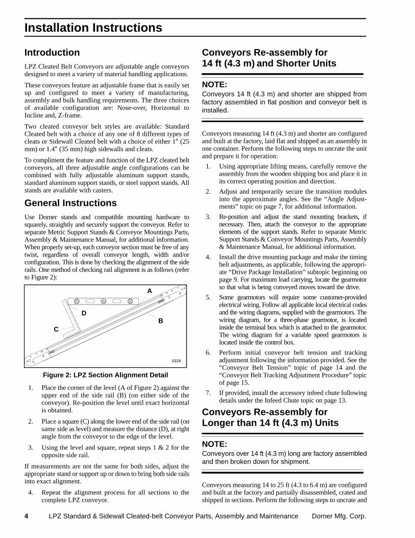
General Instructions Use Dorner stands and compatible mounting hardware tosquarely, straightly and securely support the conveyor. Refer toseparate Metric Support Stands & Conveyor Mountings Parts,Assembly & Maintenance Manual, for additional information.When properly set-up, each conveyor section must be free of anytwist, regardless of overall conveyor length, width and/orconfiguration. This is done by checking the alignment of the siderails. One method of checking rail alignment is as follows (referto Figure 2):
Figure 2: LPZ Section Alignment Detail
A
BC
D
0329
1. Place the corner of the level (A of Figure 2) against theupper end of the side rail (B) (on either side of theconveyor). Re-position the level until exact horizontalis obtained.
2. Place a square (C) along the lower end of the side rail (onsame side as level) and measure the distance (D), at rightangle from the conveyor to the edge of the level.
3. Using the level and square, repeat steps 1 & 2 for theopposite side rail.
If measurements are not the same for both sides, adjust theappropriate stand or support up or down to bring both side railsinto exact alignment.
4. Repeat the alignment process for all sections to thecomplete LPZ conveyor.
Conveyors Re-assembly for14 ft (4.3 m) and Shorter Units
NOTE:Conveyors 14 ft (4.3 m) and shorter are shipped fromfactory assembled in flat position and conveyor belt isinstalled.
Conveyors measuring 14 ft (4.3 m) and shorter are configuredand built at the factory, laid flat and shipped as an assembly inone container. Perform the following steps to uncrate the unitand prepare it for operation:
1. Using appropriate lifting means, carefully remove theassembly from the wooden shipping box and place it inits correct operating position and direction.
2. Adjust and temporarily secure the transition modulesinto the approximate angles. See the “Angle Adjust-ments” topic on page 7, for additional information.
3. Re-position and adjust the stand mounting brackets, ifnecessary. Then, attach the conveyor to the appropriateelements of the support stands. Refer to separate MetricSupport Stands & Conveyor Mountings Parts, Assembly& Maintenance Manual, for additional information.
4. Install the drive mounting package and make the timingbelt adjustments, as applicable, following the appropri-ate “Drive Package Installation” subtopic beginning onpage 9. For maximum load carrying, locate the gearmotorso that what is being conveyed moves toward the drive.
5. Some gearmotors will require some customer-providedelectrical wiring. Follow all applicable local electrical codesand the wiring diagrams, supplied with the gearmotors. Thewiring diagram, for a three-phase gearmotor, is locatedinside the terminal box which is attached to the gearmotor.The wiring diagram for a variable speed gearmotors islocated inside the control box.
6. Perform initial conveyor belt tension and trackingadjustment following the information provided. See the“Conveyor Belt Tension” topic of page 14 and the“Conveyor Belt Tracking Adjsutment Procedure” topicof page 15.
7. If provided, install the accessory infeed chute followingdetails under the Infeed Chute topic on page 13.
Conveyors Re-assembly forLonger than 14 ft (4.3 m) Units
NOTE:Conveyors over 14 ft (4.3 m) long are factory assembledand then broken down for shipment.
Conveyors measuring 14 to 25 ft (4.3 to 6.4 m) are configuredand built at the factory and partially disassembled, crated andshipped in sections. Perform the following steps to uncrate and
Installation Instructions
Dorner Mfg. Corp. LPZ Standard & Sidewall Cleated-belt Conveyor Parts, Assembly and Maintenance 5
re-assemble the sections into a ready-to-operate completeconveyor assembly:
1. Using appropriate lifting means, carefully remove thevarious sections, from their wooden shipping boxes,and position them into the correct position, sequenceand operating direction.
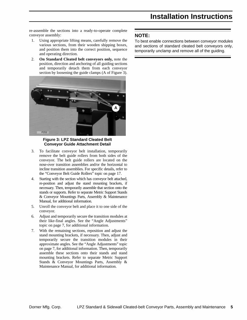
2. On Standard Cleated belt conveyors only, note theposition, direction and anchoring of all guiding sectionsand temporarily detach them from each conveyorsection by loosening the guide clamps (A of Figure 3).
Figure 3: LPZ Standard Cleated BeltConveyor Guide Attachment Detail
A
PZ02
3. To facilitate conveyor belt installation, temporarilyremove the belt guide rollers from both sides of theconveyor. The belt guide rollers are located on thenose-over transition assemblies and/or the horizontal toincline transition assemblies. For specific details, refer tothe “Conveyor Belt Guide Rollers” topic on page 17.
4. Starting with the section which has conveyor belt attached,re-position and adjust the stand mounting brackets, ifnecessary. Then, temporarily assemble that section onto thestands or supports. Refer to separate Metric Support Stands& Conveyor Mountings Parts, Assembly & MaintenanceManual, for additional information.
5. Unroll the conveyor belt and place it to one side of theconveyor.
6. Adjust and temporarily secure the transition modules attheir like-final angles. See the “Angle Adjustments”topic on page 7, for additional information.
7. With the remaining sections, reposition and adjust thestand mounting brackets, if necessary. Then, adjust andtemporarily secure the transition modules in theirapproximate angles. See the “Angle Adjustments” topicon page 7, for additional information. Then, temporarilyassemble these sections onto their stands and standmounting brackets. Refer to separate Metric SupportStands & Conveyor Mountings Parts, Assembly &Maintenance Manual, for additional information.
NOTE:To best enable connections between conveyor modulesand sections of standard cleated belt conveyors only,temporarily unclamp and remove all of the guiding.
Installation Instructions

6 LPZ Standard & Sidewall Cleated-belt Conveyor Parts, Assembly and Maintenance Dorner Mfg. Corp.
8. Refer to Figure 4 and connect adjoining LPZ sections inthe following manner:
a. Loosen (but not remove) the four (4) M6 x 12 mmcap screws (B of Figure 4), on both sides of theconveyor.
b. Bring both conveyor sections into close proxim-ity and align the T-bars (D) with the T-slots (C) inthe adjoining conveyor section.
c. While guiding the T-bars into the T-slots, slide thetransition module of the one conveyor sectioninto the open-end of the other conveyor section.
d. Continue to move the two sections together untilthe inner plates contact.
e. Tightly secure all four M6 x 12 mm cap screws,on both sides of the conveyor.
Figure 4: LPZ Section Connection Detail
B
D
C
PZ03
9. Install the conveyor belt around the sections. For theseprocedures, refer to the Conveyor Belt Replacementtopic on page 20.
After the conveyor belt has been slid into position, besure to reconnect and re-secure the same mountingbracket and attaching hardware to securely re-anchorthe stand to the conveyor.
10. On Standard Cleated belt conveyors only, replace theguiding, following details described under the “Stan-dard Cleated Belt Conveyor Guiding” topic on page 17.
11. Install drive mounting package and make the timing beltadjustments, as applicable, following the appropriate“Drive Package Installation” subtopic beginning onpage 9.
12. Perform initial conveyor belt tension and trackingadjustment following the information provided. See the“Conveyor Belt Tension” topic of page 14 and the“Conveyor Belt Tracking Adjustment Procedure” topicof page 15.
13. As applicable, install the accessory infeed chute follow-ing details on page 13.
Dorner Mfg. Corp. LPZ Standard & Sidewall Cleated-belt Conveyor Parts, Assembly and Maintenance 7
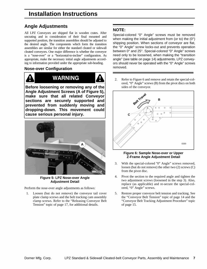
Angle AdjustmentsAll LPZ Conveyors are shipped flat in wooden crates. Afteruncrating and in consideration of their final mounted andsupported position, the transition assemblies should be adjusted tothe desired angle. The components which form the transitionassemblies are similar for either the standard cleated or sidewallcleated conveyors. One major difference is whether the conveyoris a “nose-over” or a “horizontal-to-incline” configuration. Asappropriate, make the necessary initial angle adjustments accord-ing to information provided under the appropriate sub-heading.
Nose-over Configuration
Before loosening or removing any of theAngle Adjustment Screws (A of Figure 5),make sure that all related Conveyorsections are securely supported andprevented from suddenly moving anddropping-down. This movement couldcause serious personal injury.
Ç Ç
PZ02
Figure 5: LPZ Nose-over AngleAdjustment Detail
A
Perform the nose-over angle adjustments as follows:
1. Loosen (but do not remove) the conveyor tail coverplate clamp screws and the belt tracking cam assemblyclamp screws. Refer to the “Releasing Conveyor BeltTension” topic of page 17, for additional details.
NOTE:Special-colored “0° Angle” screws must be removedwhen making the initial adjustment from (or to) the (0°)shipping position. When sections of conveyor are flat,the “0° Angle” screw locks-out and prevents operationbetween 0° and 25°. Special-colored “0° Angle” screwsneed only to be loosened, when making the “transitionangle” (see table on page 14) adjustments. LPZ convey-ors should never be operated with the “0° Angle” screwsremoved.
2. Refer to Figure 6 and remove and retain the special-col-ored, “0° Angle” screws (B) from the pivot discs on bothsides of the conveyor.
Figure 6: Sample Nose-over or UpperZ-Frame Angle Adjustment Detail
C
B
0330
3. With the special-colored “0° Angle” screws removed,loosen (but do not remove) the other two (2) screws (C)from the pivot disc.
4. Pivot the section to the required angle and tighten thetwo adjustment screws (loosened in the step 3). Also,replace (as applicable) and re-secure the special-col-ored, “0° Angle” screws.
5. Restore proper conveyor belt tension and tracking. Seethe “Conveyor Belt Tension” topic of page 14 and the“Conveyor Belt Tracking Adjustment Procedure” topicof page 15.
Installation Instructions
8 LPZ Standard & Sidewall Cleated-belt Conveyor Parts, Assembly and Maintenance Dorner Mfg. Corp.
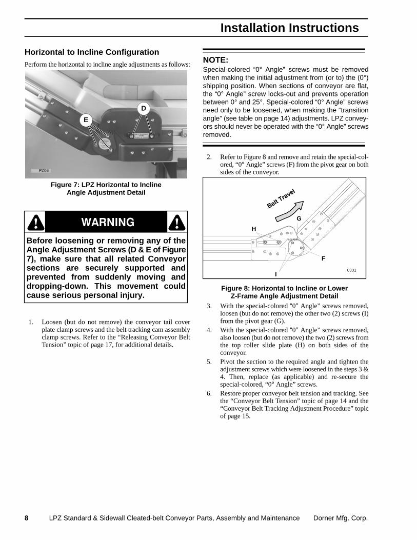
Horizontal to Incline ConfigurationPerform the horizontal to incline angle adjustments as follows:
Figure 7: LPZ Horizontal to InclineAngle Adjustment Detail
D
E
PZ05
Before loosening or removing any of theAngle Adjustment Screws (D & E of Figure7), make sure that all related Conveyorsections are securely supported andprevented from suddenly moving anddropping-down. This movement couldcause serious personal injury.
Ç Ç
1. Loosen (but do not remove) the conveyor tail coverplate clamp screws and the belt tracking cam assemblyclamp screws. Refer to the “Releasing Conveyor BeltTension” topic of page 17, for additional details.
NOTE:Special-colored “0° Angle” screws must be removedwhen making the initial adjustment from (or to) the (0°)shipping position. When sections of conveyor are flat,the “0° Angle” screw locks-out and prevents operationbetween 0° and 25°. Special-colored “0° Angle” screwsneed only to be loosened, when making the “transitionangle” (see table on page 14) adjustments. LPZ convey-ors should never be operated with the “0° Angle” screwsremoved.
2. Refer to Figure 8 and remove and retain the special-col-ored, “0° Angle” screws (F) from the pivot gear on bothsides of the conveyor.
Figure 8: Horizontal to Incline or LowerZ-Frame Angle Adjustment Detail
H
I
F
G
0331
3. With the special-colored “0° Angle” screws removed,loosen (but do not remove) the other two (2) screws (I)from the pivot gear (G).
4. With the special-colored “0° Angle” screws removed,also loosen (but do not remove) the two (2) screws fromthe top roller slide plate (H) on both sides of theconveyor.
5. Pivot the section to the required angle and tighten theadjustment screws which were loosened in the steps 3 &4. Then, replace (as applicable) and re-secure thespecial-colored, “0° Angle” screws.
6. Restore proper conveyor belt tension and tracking. Seethe “Conveyor Belt Tension” topic of page 14 and the“Conveyor Belt Tracking Adjustment Procedure” topicof page 15.
Installation Instructions

Dorner Mfg. Corp. LPZ Standard & Sidewall Cleated-belt Conveyor Parts, Assembly and Maintenance 9
Drive Package Installation
NOTE:For maximum load carrying, locate the gearmotor so thatwhat is being conveyed moves toward the drive.
Bottom Mount Installation & Initial TimingBelt Tension Adjustment The bottom mount package can be set up in either one of twopositions (A or Dof Figure 9).
Figure 9: Bottom Drive Mounting Detail
Position A
1
2
Position D
1
2
03420343
The conveyor belt can be driven in either one of two directions(1 or 2of Figure 9). Arrows show belt travel direction.
Belt travel direction must correspond toarrow decals located on transitionsections to prevent the creation of pinchpoints which could cause seriouspersonal injury.
Ç Ç
1. Refer to Figure 11 and attach the gearmotor (E) and themotor mounting plate (H) to the conveyor (F) using oneM6 x 30 mm socket head cap screw (I) in the topmounting hole of the mounting plate, two M6 x 16mm socket head cap screws (J) in middle holes andthree M6 x 20 mm socket head cap screws (K) inbottom holes.
NOTE:The lower set (of 4) gearmotor mounting plate holes (Gof of Figure 11) is only used when both gearmotor andconveyor shafts will have 16 tooth pulleys mounted tothem. All other pulley combinations, use the upper set ofmounting plate holes.
2. Assemble the drive and driven pulleys (M and/or L) and
timing belt (N). Place a square key (O of Figure 11) intothe keyway on the gearmotor and conveyor shafts. Installthe pulleys so that the timing belt is centered on the belttensioning roller assembly and the pulleys are in line witheach other. Tighten the pulley set screws (Q) or TaperLock� bushing screws (P), which fasten the pulleys to theshafts. Determine which direction the conveyor belt istraveling and position the tensioning roller assembly onslack side of the timing belt (Figure 10).
3. Adjust timing belt tension by loosening the M12 x 25 mmsocket head cap screw (R) and sliding the belt tensioningroller assembly against the belt. Tension should bemeasured at mid-point (C of Figure 10) on the tensionside of the timing belt. As a starting point for thetensioning process, there should be a 1/8″ (3 mm)deflection with 6 lb (3kg or 26 N) of force.
B
B
Figure 10: Bottom Drive Timing BeltAdjustment Detail
2
C
1
0294 0295
C
4. Every timing belt application exhibits its own individualoperating characteristics. The optimum timing belt tensionshould be determined experimentally.
If necessary, continue to slide the tensioning rollerassembly against the timing belt until the belt istensioned so as to prevent jumping of teeth under themost severe conditions which the drive will encounter.Tighten the M12 x 25 mm socket head cap screw aftertension requirements are achieved.
IMPORTANT:Do not over tension the timing belt. Over tensioning maycause reduced belt life or bearing and drive damage.
5. Attach the bottom drive cover (S of Figure 11) usingfour M4 x 10 mm button head cap screws (T).
Installation Instructions
10 LPZ Standard & Sidewall Cleated-belt Conveyor Parts, Assembly and Maintenance Dorner Mfg. Corp.
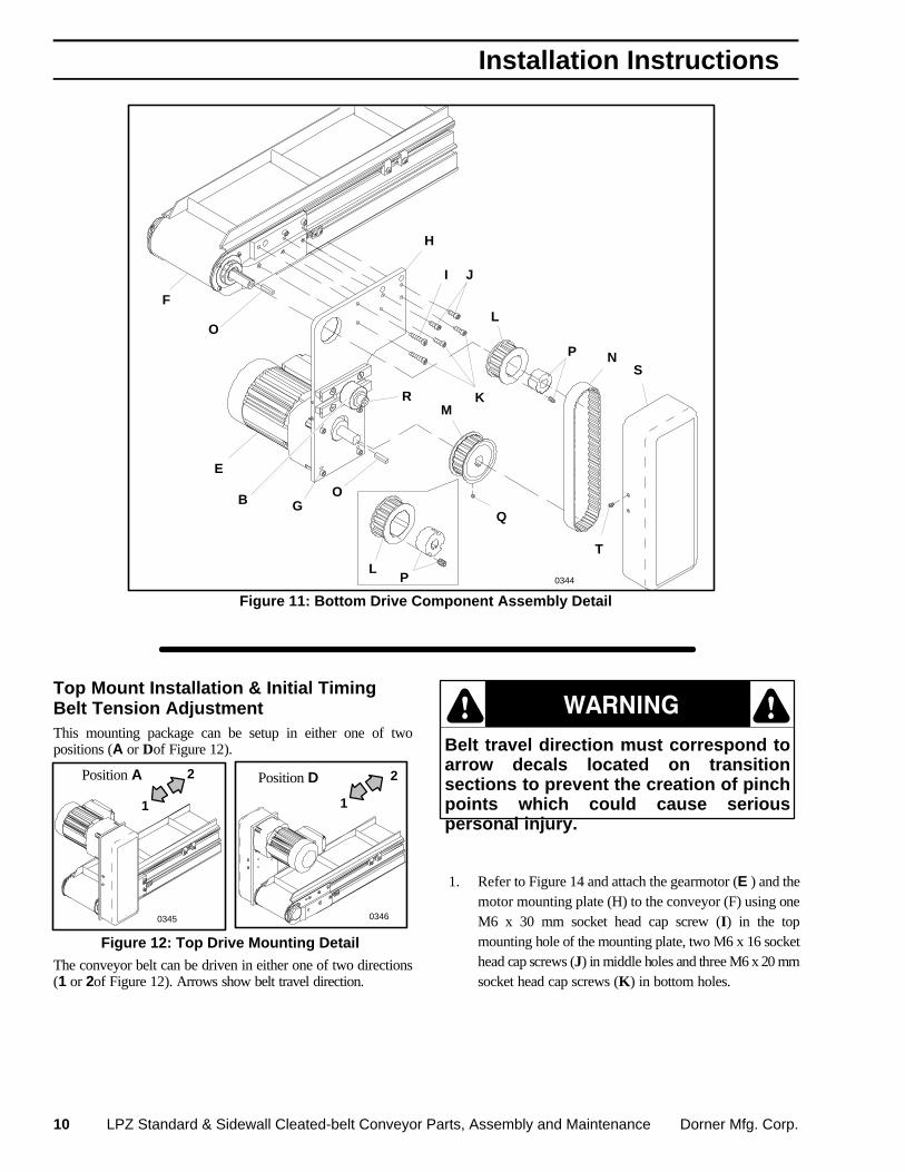
Figure 11: Bottom Drive Component Assembly Detail
E
F
I J
K
H
O
O
B
P
L
LP
M
Q
T
SN
G
R
0344
Top Mount Installation & Initial TimingBelt Tension AdjustmentThis mounting package can be setup in either one of twopositions (A or Dof Figure 12).
Position A
1
2 Position D
Figure 12: Top Drive Mounting Detail
1
2
0345 0346
The conveyor belt can be driven in either one of two directions(1 or 2of Figure 12). Arrows show belt travel direction.
Belt travel direction must correspond toarrow decals located on transitionsections to prevent the creation of pinchpoints which could cause seriouspersonal injury.
Ç ÇÇ
1. Refer to Figure 14 and attach the gearmotor (E ) and themotor mounting plate (H) to the conveyor (F) using oneM6 x 30 mm socket head cap screw (I) in the topmounting hole of the mounting plate, two M6 x 16 sockethead cap screws (J) in middle holes and three M6 x 20 mmsocket head cap screws (K) in bottom holes.
Installation Instructions

Dorner Mfg. Corp. LPZ Standard & Sidewall Cleated-belt Conveyor Parts, Assembly and Maintenance 11
NOTE:The upper set (of 4) gearmotor mounting plate holes (Gof of Figure 14) is only used when both gearmotor andconveyor shafts will have 16 tooth pulleys mounted tothem. All other pulley combinations, use the lower set ofmounting plate holes.
2. Assemble the drive and driven pulleys (M and/or L) andtiming belt (N). Place a square key (O) into the keywayon the gearmotor and conveyor shafts. Install the pulleysso that the timing belt is centered on the belt tensioningroller assembly and the pulleys are in line with each other.Tighten the pulley set screws (P) or Taper Lock� bushingscrews (Q), which fasten the pulleys to the shafts.Determine which direction the conveyor belt is travel-ing and position the tensioning roller assembly on theslack side of the timing belt (Figure 13).
3. Adjust timing belt tension by loosening the M12 x 25mm socket head cap screw (R of Figure 14) and slidingthe belt tensioning roller assembly against the belt.Tension should be measured at mid-point (C of Figure13) of on the tension side of the timing belt. As a startingpoint for the tensioning process, there should be a 1/8″(3 mm) deflection with 6 lb (3kg or 26 N) of force.
B
Figure 13: Top Drive Timing BeltAdjustment Detail
B
21C
0297 0296
C
4. Every timing belt application exhibits its own individualoperating characteristics. The optimum timing belt tensionshould be determined experimentally.If necessary, continue to slide the tensioning rollerassembly against the timing belt until the belt istensioned so as to prevent jumping of teeth under themost severe conditions which the drive will encounter.Tighten the M12 x 25 mm socket head cap screw aftertension requirements are achieved.
IMPORTANT:Do not over tension the timing belt. Over tensioning maycause reduced belt life or bearing and drive damage.
5. Attach the top drive cover (S of Figure 14) using four M4x 10 mm button head cap screws (T).
Figure 14: Top Drive Component Assembly Detail
H
M
TS
J
P
R
O
O
K
I
L
N
Q
L Q
F
E
G
B
0347
Installation Instructions
12 LPZ Standard & Sidewall Cleated-belt Conveyor Parts, Assembly and Maintenance Dorner Mfg. Corp.
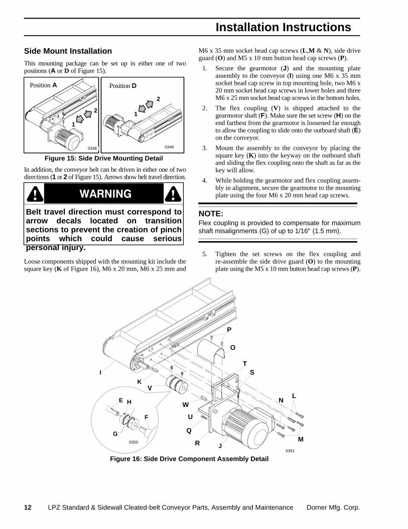
Side Mount InstallationThis mounting package can be set up in either one of twopositions (A or D of Figure 15).
Position A
1
2
Position D
1
2
Figure 15: Side Drive Mounting Detail
0348 0349
In addition, the conveyor belt can be driven in either one of twodirections (1 or 2 of Figure 15). Arrows show belt travel direction.
Belt travel direction must correspond toarrow decals located on transitionsections to prevent the creation of pinchpoints which could cause seriouspersonal injury.
Ç Ç
Loose components shipped with the mounting kit include thesquare key (K of Figure 16), M6 x 20 mm, M6 x 25 mm and
M6 x 35 mm socket head cap screws (L,M & N), side driveguard (O) and M5 x 10 mm button head cap screws (P).
1. Secure the gearmotor (J) and the mounting plateassembly to the conveyor (I) using one M6 x 35 mmsocket head cap screw in top mounting hole, two M6 x20 mm socket head cap screws in lower holes and threeM6 x 25 mm socket head cap screws in the bottom holes.
2. The flex coupling (V) is shipped attached to thegearmotor shaft (F). Make sure the set screw (H) on theend farthest from the gearmotor is loosened far enoughto allow the coupling to slide onto the outboard shaft (E)on the conveyor.
3. Mount the assembly to the conveyor by placing thesquare key (K) into the keyway on the outboard shaftand sliding the flex coupling onto the shaft as far as thekey will allow.
4. While holding the gearmotor and flex coupling assem-bly in alignment, secure the gearmotor to the mountingplate using the four M6 x 20 mm head cap screws.
NOTE:Flex coupling is provided to compensate for maximumshaft misalignments (G) of up to 1/16″ (1.5 mm).
5. Tighten the set screws on the flex coupling andre-assemble the side drive guard (O) to the mountingplate using the M5 x 10 mm button head cap screws (P).
Figure 16: Side Drive Component Assembly Detail
F
G
E
T
M
V
R
P
W
U
K
N
O
L
S
J
I
H
0350
0351
Q
Installation Instructions
Dorner Mfg. Corp. LPZ Standard & Sidewall Cleated-belt Conveyor Parts, Assembly and Maintenance 13
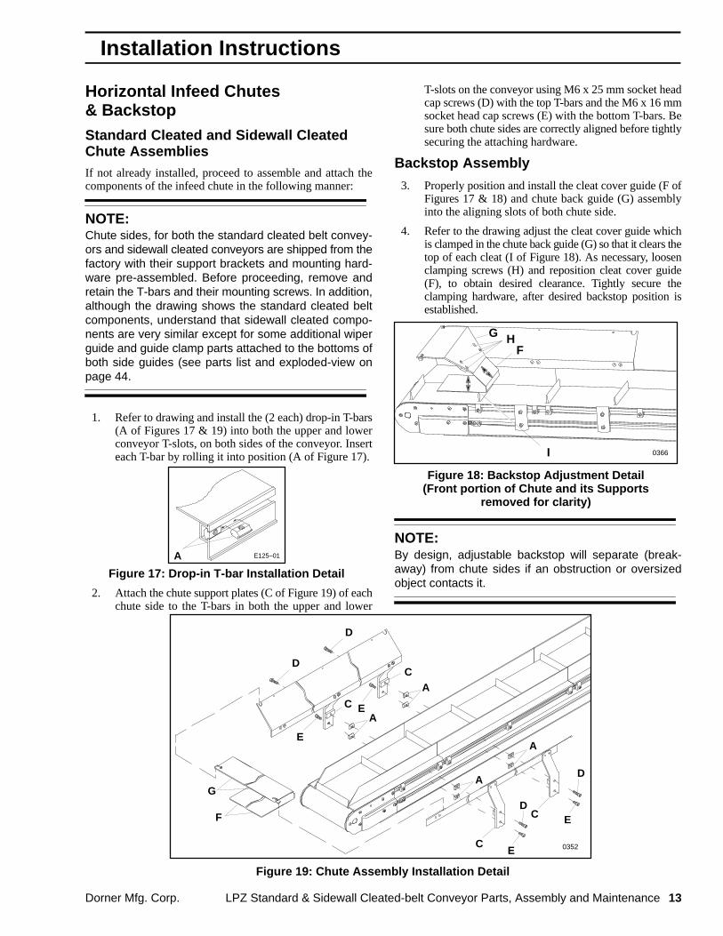
Horizontal Infeed Chutes& BackstopStandard Cleated and Sidewall CleatedChute AssembliesIf not already installed, proceed to assemble and attach thecomponents of the infeed chute in the following manner:
NOTE:Chute sides, for both the standard cleated belt convey-ors and sidewall cleated conveyors are shipped from thefactory with their support brackets and mounting hard-ware pre-assembled. Before proceeding, remove andretain the T-bars and their mounting screws. In addition,although the drawing shows the standard cleated beltcomponents, understand that sidewall cleated compo-nents are very similar except for some additional wiperguide and guide clamp parts attached to the bottoms ofboth side guides (see parts list and exploded-view onpage 44.
1. Refer to drawing and install the (2 each) drop-in T-bars(A of Figures 17 & 19) into both the upper and lowerconveyor T-slots, on both sides of the conveyor. Inserteach T-bar by rolling it into position (A of Figure 17).
Figure 17: Drop-in T-bar Installation Detail
E125–01A
2. Attach the chute support plates (C of Figure 19) of eachchute side to the T-bars in both the upper and lower
T-slots on the conveyor using M6 x 25 mm socket headcap screws (D) with the top T-bars and the M6 x 16 mmsocket head cap screws (E) with the bottom T-bars. Besure both chute sides are correctly aligned before tightlysecuring the attaching hardware.
Backstop Assembly
3. Properly position and install the cleat cover guide (F ofFigures 17 & 18) and chute back guide (G) assemblyinto the aligning slots of both chute side.
4. Refer to the drawing adjust the cleat cover guide whichis clamped in the chute back guide (G) so that it clears thetop of each cleat (I of Figure 18). As necessary, loosenclamping screws (H) and reposition cleat cover guide(F), to obtain desired clearance. Tightly secure theclamping hardware, after desired backstop position isestablished.
Figure 18: Backstop Adjustment Detail(Front portion of Chute and its Supports
removed for clarity)
0366
G
I
FH
NOTE:By design, adjustable backstop will separate (break-away) from chute sides if an obstruction or oversizedobject contacts it.
Figure 19: Chute Assembly Installation Detail
A
A
A
A
C
C
C
C
E
E
E
E
D
DG
F
0352
D
D
Installation Instructions

14 LPZ Standard & Sidewall Cleated-belt Conveyor Parts, Assembly and Maintenance Dorner Mfg. Corp.
IMPORTANT:
The cleated conveyor belt is the single most importantcomponent of an LPZ conveyor. Therefore, Dorner rec-ommends that both correct conveyor belt tension andproper belt tracking be correctly established before theconveyor is put into operation. Conveyor belt tensioningand tracking is not difficult, especially with the patentedDorner “rack and pinion” tensioning system and camtracking mechanism.
Conveyor Belt Tension
The following procedure is used to tension the conveyor belt.The conveyor uses a rack and pinion assembly (G of Figure 20)to take up conveyor belt slack and achieve proper conveyorbelt operating tension. To adjust the belt tension:
0353
DB
A
F
Figure 20
G
C
E
1. Locate the tension end (B) of the conveyor, identifiedwith a label (C).
2. If engaged, loosen and slide belt tracking cam assem-blies (D) towards the center of the conveyor on bothsides of the tension end.
3. Loosen tail cover plate clamping screws (E) on bothsides of the tension end.
4. Insert a 5 mm hex key wrench (F) into either end of thepinion (A).
Figure 21: Conveyor Belt Buckling Causedby Over-tensioning
DO NOT ATTEMPT TO RUN CONVEYOR WHENTHIS CONDITION EXISTS!
H
PZ06
5. Rotate the pinion to extend the tensioning end, and applya sufficient tension to eliminate drive pulley slippage.But, do not apply too much tension to cause the conveyorbelt to bow or buckle (H of Figure 21) or otherwise topop-out from under the guide rollers on either side of theconveyor, in the area of the transition modules.
NOTE:Refer to the table provided for maximum recommendedtension pinion torque values and maximum conveyorloads for different angles. Choose the appropriate valuewhich relates to your particular requirements.
StandardCleated Belt
SidewallCleated Belt
TransitionAngle
TensionPinionTorque
MaximumConveyor
Load
TensionPinionTorque
MaximumConveyor
Load
in-lb Nm lb kg in-lb Nm lb kg
25° * 25 2.8 25 11.3 50 5.6 75 34
30° * 35 3.9 50 22.7 60 6.8 100 45.4
35° 50 5.6 75 34 70 7.9 100 45.4
40° 75 8.5 100 45.4 80 9.0 100 45.4
45° 75 8.5 100 45.4 80 9.0 100 45.4
50° 75 8.5 100 45.4 80 9.0 100 45.4
55° 75 8.5 100 45.4 80 9.0 100 45.4
60° 75 8.5 100 45.4 80 9.0 100 45.4
* Not available on 18″ & 24″ (457 & 610 mm) width conveyors
6. While holding the pinion in the tensioned position, tightencover plate screws on both sides of the conveyor. Torque themounting screws to approximately 18 in-lb (2 Nm).
7. On Standard Cleated belt conveyors only, the guidingmust be in place before proceeding to adjust thetracking.
Start-up & Preliminary Adjustments
Dorner Mfg. Corp. LPZ Standard & Sidewall Cleated-belt Conveyor Parts, Assembly and Maintenance 15
Conveyor Belt TrackingAdjustment Procedure
Although all potentially hazardous areasof the Cleated Belt conveyors areshielded by bolt-on guards and there areno exposed pinch-point, the cleatsthemselves may create unforeseen catchpoints, especially when loose-fittingclothing is being worn. Exerciseappropriate caution everywhere aroundthe cleated belt.
Ç Ç
IMPORTANT:To avoid permanent damage to the conveyor belt duringinitial tracking adjustment, conveyor must only be jogged(started and stopped), instead of run continuously, untilthe following initial setting is established.
Make sure the belt is properly tensioned and that the conveyoris straight and level in all directions within the confines of theconveyor.
This conveyor is equipped with an articular linkage whichallows the pulley to be positioned at a slight angle to facilitatebelt tracking.
Check both ends of the conveyor for proper belt tracking. Thebelt should track centered between the tail plates on both endsof the conveyor. Conveyor belt tracking should always beadjusted on the discharge end of conveyor first. Then, checkthe tracking on the opposite (infeed) end of the conveyor andreadjust, if necessary.
To adjust belt tracking:
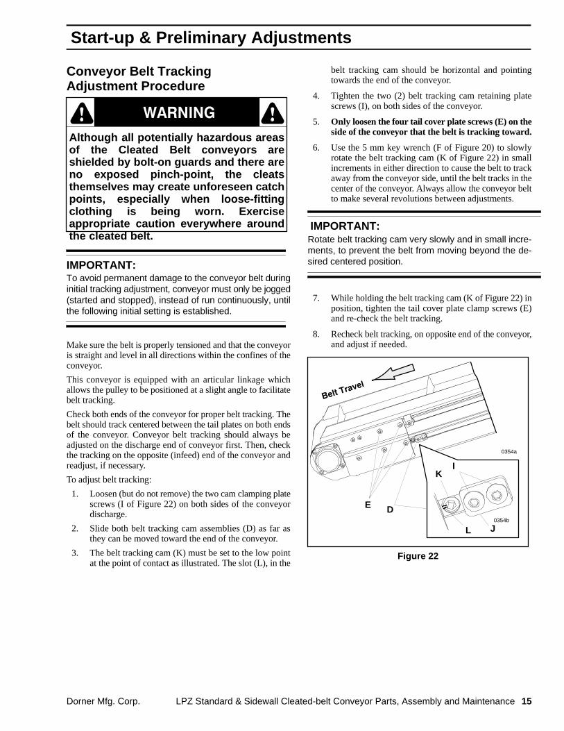
1. Loosen (but do not remove) the two cam clamping platescrews (I of Figure 22) on both sides of the conveyordischarge.
2. Slide both belt tracking cam assemblies (D) as far asthey can be moved toward the end of the conveyor.
3. The belt tracking cam (K) must be set to the low pointat the point of contact as illustrated. The slot (L), in the
belt tracking cam should be horizontal and pointingtowards the end of the conveyor.
4. Tighten the two (2) belt tracking cam retaining platescrews (I), on both sides of the conveyor.
5. Only loosen the four tail cover plate screws (E) on theside of the conveyor that the belt is tracking toward.
6. Use the 5 mm key wrench (F of Figure 20) to slowlyrotate the belt tracking cam (K of Figure 22) in smallincrements in either direction to cause the belt to trackaway from the conveyor side, until the belt tracks in thecenter of the conveyor. Always allow the conveyor beltto make several revolutions between adjustments.
IMPORTANT:Rotate belt tracking cam very slowly and in small incre-ments, to prevent the belt from moving beyond the de-sired centered position.
7. While holding the belt tracking cam (K of Figure 22) inposition, tighten the tail cover plate clamp screws (E)and re-check the belt tracking.
8. Recheck belt tracking, on opposite end of the conveyor,and adjust if needed.
Figure 22
I
JL
K
0354a
0354b
E D
Start-up & Preliminary Adjustments
16 LPZ Standard & Sidewall Cleated-belt Conveyor Parts, Assembly and Maintenance Dorner Mfg. Corp.
Inspection
Inspect the conveyor belt for:
� Surface cuts or wear
� Tracking problems
� Worn edges
� Stalling or slipping
� Stretching or breaking
� Belts that walk to one side
� Non-uniform movement of the conveyor belt
� Rough edges on belt
Problem Identification
Belts that walk to one side indicate:
� Belt tracking incorrectly. Refer to “Conveyor BeltTracking Adjustment” on page 15.
� Twisted or damaged conveyor frame
� Dirt accumulating on the outside diameter of thepulleys.
Non-uniform movement indicates:
� Excessive load on conveyor belt.
� Intermittent jam or drive train problems.When a problem is identified, perform correctivemaintenance on the conveyor.
� Conveyor or drive timing belt is not properlytensioned.
Rough edges on belt could indicate:
� Belt tracking incorrectly. Refer to “Conveyor BeltTracking Adjustment” on page 15.
� Foreign material inside the conveyor
NOTE:Refer to Troubleshooting Guide on page 21.
Cleaning
IMPORTANT:Do not use belt cleaners that contain alcohol, acetone,Methyl Ethyl Ketone (MEK) or other harsh chemicals.
Use Dorner Belt Cleaner, part number 625619, orequivalent. Mild soap and water may also be used. Donot soak the belt.
Maintenance - Conveyor Belt

Dorner Mfg. Corp. LPZ Standard & Sidewall Cleated-belt Conveyor Parts, Assembly and Maintenance 17
Conveyor Preparations
To prevent injury, make sure all electricalpower has been disconnected before youperform any maintenance, make any ad-justments or replace any components.In addition, the weight of the gearmotor isall on one end of the conveyor. This couldcause the conveyor and stand to tip overwhen the anchor components are re-moved. There should be some form ofextra support (O of Figure 29) for the gear-motor while the conveyor belt is beingchanged.
Ç Ç
1. Disconnect all electrical power sources.
2. To facilitate re-assembly, mark any critical locations foraccessory attachments along the entire side of theconveyor frame from which the belt is going to beremoved.
3. Wherever possible, conveyor belt should always beremoved from the side opposite the gearmotor, controls,stops or other attached accessories which could inter-fere with belt removal.
Standard Cleated Belt Conveyor Guiding
Figure 23: Standard Cleated Belt ConveyorGuiding Removal Detail
A
B0338
NOTE:Several guiding configurations are provided for the Stan-dard Cleated belt conveyors with respect to the length ofthe conveyor section, the type of transition module andthe direction of belt travel. See parts illustrations begin-ning on page 35.
The LPZ Standard Cleated belt conveyor is provided with guiding(A of Figure 23) on both sides of each section. When the conveyorbelt is going to be replaced, the guiding must be temporarilyremoved from the side opposite the gearmotor, so that the existingconveyor belt can be removed from that section and the new beltinstalled.
Be sure to mark (or make appropriate notations) of the anchorclamp positions and guide section locations. Then, removeguiding from the side of the conveyor opposite the gearmotor.
To remove the guiding, refer to Figure 23 and loosen, removeand retain the guide clamps (B). Guide replacement is inreverse sequence of removal.
Releasing Conveyor Belt Tension
The following procedure should be used to release theconveyor belt tension, before proceeding to remove the oldbelt. These same procedures apply to both Standard Cleatedbelt and Sidewall Cleated belt conveyors.
1. On a Standard Cleated belt conveyor only, removeand retain the tail guide sections (C of Figure 24), byloosening, removing and retaining the guide clamps(B), on both sides of the conveyor.
2. If engaged, loosen the belt tracking cam assemblies (D),on both sides of the tensioning end (E), identified bylabel (F). Then, slide the cam assemblies toward themiddle of the conveyor.
3. Loosen the tail cover plate screws (G), on both sides ofthe tensioning end.
4. Collapse the tensioning end (E) of the conveyor bypushing it back into the conveyor frame, using the heelof your hand. This will sufficiently loosen the belt forremoval.
0353
D
C
Figure 24
F
G
B
E
Conveyor Belt Replacement & Adjustmen
18 LPZ Standard & Sidewall Cleated-belt Conveyor Parts, Assembly and Maintenance Dorner Mfg. Corp.
Conveyor Belt Guide Rollers
LPZ cleated belt conveyors are provided with conveyor beltguide roller assemblies on all nose-over and horizontal to inclinetransition assemblies. When shipped, all guide rollers assembliesare attached to their respective sections.
The conveyor belt guide roller assemblies must be temporarilyremoved from the side opposite the gearmotor, so that the existingconveyor belt can be removed from that section and the new beltinstalled.
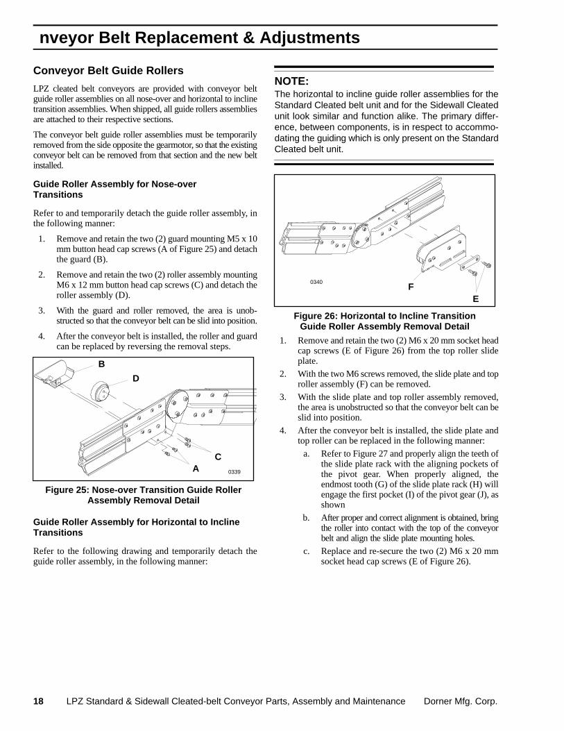
Guide Roller Assembly for Nose-overTransitions
Refer to and temporarily detach the guide roller assembly, inthe following manner:
1. Remove and retain the two (2) guard mounting M5 x 10mm button head cap screws (A of Figure 25) and detachthe guard (B).
2. Remove and retain the two (2) roller assembly mountingM6 x 12 mm button head cap screws (C) and detach theroller assembly (D).
3. With the guard and roller removed, the area is unob-structed so that the conveyor belt can be slid into position.
4. After the conveyor belt is installed, the roller and guardcan be replaced by reversing the removal steps.
Figure 25: Nose-over Transition Guide RollerAssembly Removal Detail
A
B
C
D
0339
Guide Roller Assembly for Horizontal to InclineTransitions
Refer to the following drawing and temporarily detach theguide roller assembly, in the following manner:
NOTE:The horizontal to incline guide roller assemblies for theStandard Cleated belt unit and for the Sidewall Cleatedunit look similar and function alike. The primary differ-ence, between components, is in respect to accommo-dating the guiding which is only present on the StandardCleated belt unit.
Figure 26: Horizontal to Incline TransitionGuide Roller Assembly Removal Detail
EF
0340
1. Remove and retain the two (2) M6 x 20 mm socket headcap screws (E of Figure 26) from the top roller slideplate.
2. With the two M6 screws removed, the slide plate and toproller assembly (F) can be removed.
3. With the slide plate and top roller assembly removed,the area is unobstructed so that the conveyor belt can beslid into position.
4. After the conveyor belt is installed, the slide plate andtop roller can be replaced in the following manner:
a. Refer to Figure 27 and properly align the teeth ofthe slide plate rack with the aligning pockets ofthe pivot gear. When properly aligned, theendmost tooth (G) of the slide plate rack (H) willengage the first pocket (I) of the pivot gear (J), asshown
b. After proper and correct alignment is obtained, bringthe roller into contact with the top of the conveyorbelt and align the slide plate mounting holes.
c. Replace and re-secure the two (2) M6 x 20 mmsocket head cap screws (E of Figure 26).
nveyor Belt Replacement & Adjustments

Dorner Mfg. Corp. LPZ Standard & Sidewall Cleated-belt Conveyor Parts, Assembly and Maintenance 19
Figure 27: Typical Standard Cleated BeltConveyor Horizontal to Incline Transition
Guide Roller Detail
F
I
H
J
0341
Conveyor Belt Removal
NOTE:Because conveyor belt removal and replacement in-volves temporarily disconnecting a section from a stand,it is recommended that the new conveyor belt bereplaced on each section right after the old belt isremoved. Always perform conveyor belt removal andreplacement “one section at a time” to prevent twistingthe conveyor frame or imposing undue stress on any ofthe stand attachment points.
NOTE:For additional details, refer to separate Metric SupportStands & Conveyor Mountings Parts, Assembly & Main-tenance Manual. As necessary, properly support thegearmotor end, when loosening and removing the standattachment components.
For Conveyor with Fully AdjustableAluminum Support Stands
1. Referring to Figure 28, safely and temporarily supportthe conveyor section with a sturdy support mechanism(K) (such as wooden blocks or a sawhorse).
Figure 28
M
0333
K
LN
2. Temporarily disconnect the adjustable stand by remov-ing the two (2) screws (L) which attach each adjustablestand sleeve assembly (M) to a T-bar (N) in the T-slot oneach side of the conveyor.
For Conveyors with Aluminum or SteelSupport Stand
To prevent injury from the support standtipping-over when the conveyor isuncoupled, be sure to anchor the stand tothe floor or otherwise properly stabilizethe stand before it is detached from theconveyor.
Ç Ç
1. Referring to Figure 29, safely and temporarily supportthe conveyor section with a sturdy support mechanism(O) (such as wooden blocks or a sawhorse).
2. Remove and retain the mounting clamp plate screw andclamp plate (P of Figure 29) from the conveyor.
3. Detach and retain the mounting clamp bracket (Q) fromthe top plate (R) on the side opposite the gearmotor.
Conveyor Belt Replacement & Adjustmen

20 LPZ Standard & Sidewall Cleated-belt Conveyor Parts, Assembly and Maintenance Dorner Mfg. Corp.
For All Conveyors1. Slide the old belt sideways and away from the conveyor
section (Figure 30).
2. Install the new conveyor belt on this section, followingthe information under the next topic, and replace thestand attaching hardware.
3. Continue to remove the old belt and install the new belton each conveyor section until the new belt is fullyinstalled.
Figure 29
O
PR
Q
0338
Conveyor Belt Replacement 1. Install the new belt by sliding it sideways onto the
conveyor frame opposite from the way the old belt wasremoved.
Figure 30: LPZ Conveyor Belt Being Slid OffConveyor Through Gap Created ByRemoving Aluminum or Steel Stand
Attachment Components
PZ04
2. Reverse the appropriate steps which were followedwhen removing original belt.
NOTE:On standard cleated belt conveyors, do not replace theguiding, at this time. Replace the guiding after properconveyor belt tension has been achieved.
3. Make sure all hardware, that was either removed orloosened, is replaced and properly tightened. Do not,tightly secure the tail cover plate screws, at this time.
4. Refer to Conveyor Belt Tension Adjustment informa-tion in the Start-up & Preliminary Adjustments sectionon page 14.
5. Refer to Conveyor Belt Tracking information in theStart-up & Preliminary Adjustments section on page 15.
6. After the proper belt tension and tracking is established,replace the controls, stops and other attached accesso-ries referring to the positions previously marked.
nveyor Belt Replacement & Adjustments
Dorner Mfg. Corp. LPZ Standard & Sidewall Cleated-belt Conveyor Parts, Assembly and Maintenance 21
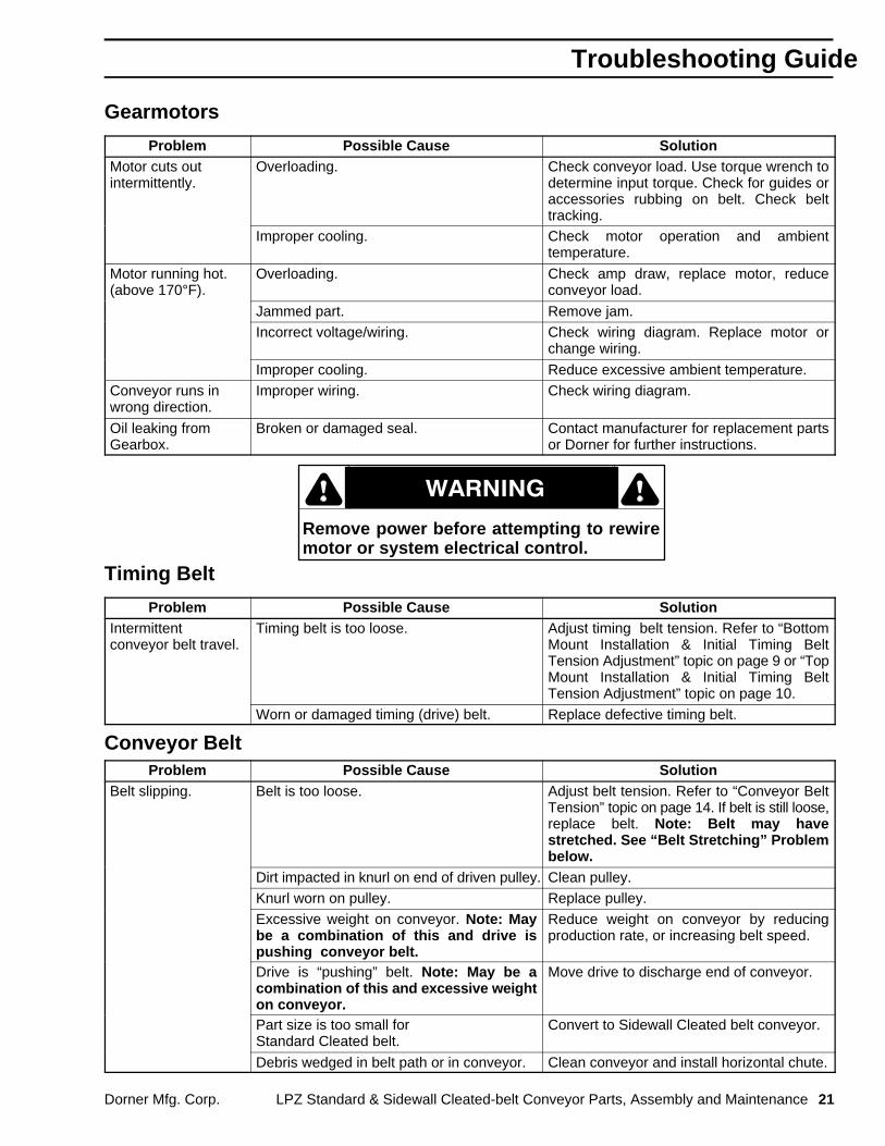
Gearmotors
Problem Possible Cause SolutionMotor cuts outintermittently.
Overloading. Check conveyor load. Use torque wrench todetermine input torque. Check for guides oraccessories rubbing on belt. Check belttracking.
Improper cooling. Check motor operation and ambienttemperature.
Motor running hot.(above 170°F).
Overloading. Check amp draw, replace motor, reduceconveyor load.
Jammed part. Remove jam.Incorrect voltage/wiring. Check wiring diagram. Replace motor or
change wiring.
Improper cooling. Reduce excessive ambient temperature.
Conveyor runs inwrong direction.
Improper wiring. Check wiring diagram.
Oil leaking fromGearbox.
Broken or damaged seal. Contact manufacturer for replacement partsor Dorner for further instructions.
Remove power before attempting to rewiremotor or system electrical control.
Ç Ç
Timing Belt
Problem Possible Cause SolutionIntermittentconveyor belt travel.
Timing belt is too loose. Adjust timing belt tension. Refer to “BottomMount Installation & Initial Timing BeltTension Adjustment” topic on page 9 or “TopMount Installation & Initial Timing BeltTension Adjustment” topic on page 10.
Worn or damaged timing (drive) belt. Replace defective timing belt.
Conveyor BeltProblem Possible Cause Solution
Belt slipping. Belt is too loose. Adjust belt tension. Refer to “Conveyor BeltTension” topic on page 14. If belt is still loose,replace belt. Note: Belt may havestretched. See “Belt Stretching” Problembelow.
Dirt impacted in knurl on end of driven pulley. Clean pulley.Knurl worn on pulley. Replace pulley.
Excessive weight on conveyor. Note: Maybe a combination of this and drive ispushing conveyor belt.
Reduce weight on conveyor by reducingproduction rate, or increasing belt speed.
Drive is “pushing” belt. Note: May be acombination of this and excessive weighton conveyor.
Move drive to discharge end of conveyor.
Part size is too small for Standard Cleated belt.
Convert to Sidewall Cleated belt conveyor.
Debris wedged in belt path or in conveyor. Clean conveyor and install horizontal chute.
Troubleshooting Guide

22 LPZ Standard & Sidewall Cleated-belt Conveyor Parts, Assembly and Maintenance Dorner Mfg. Corp.
Conveyor Belt (continued)
Problem Possible Cause SolutionBelt stretching. Solvent or chemical reaction with belt. Remove solvent. Test solvent with belt
sample.
Belt repeatedly stalled, causing pulley towear or “burn” in to backside of belt.
Replace belt and identify reason for stalling.
Cuts on belt surface. Sharp parts penetrating belt surface. Install baffle to reduce energy of falling part.
Guides or accessories rubbing on belt. Adjust as necessary.Worn belt edges. Debris impacted on pulleys can cause belt
tracking problems.Clean pulleys. Correct source ofcontamination. See Belt Tracking Incorrectlybelow.
Belt tracking incorrectly. Refer to “Conveyor Belt Tracking AdjustmentProcedure” topic on page 15.
Belt breaking atsplice.
Solvent or chemical reaction with belt. Remove solvent. Test solvent with beltsample.
Belt trackingincorrectly.
Pulleys not perpendicular to conveyor centerline.
Inspect and reposition pulleys, if necessary.
Frame misalignment. Note: Framemounting surface may be misaligned.
Frame mounting must be straight and withinthe same plane. Check with a straight edgeand level.
Frame distortion due to damage. Repair or replace frame components and/orbed plate. Check with a straight edge.
Top guide roller gear rack not in correctposition.
Re-adjust guide roller per details under“Conveyor Belt Guide Rollers” topic on page18.
Belt tracking cam incorrectly adjusted. Refer to “Conveyor Belt Tracking AdjustmentProcedure” topic on page 15.
Belt bulging orpopping-out at guiderollers.
Belt over-tensioned. Re-adjust belt tension. Refer to “ConveyorBelt Tension” topic on page 14.
Excessive weight on conveyor. Reduce weight on conveyor by reducingproduction rate, or increasing belt speed.
Belt slipping. Elevation angle too small for load. Increase elevation angle and readjust belttension and tracking, as required.
Troubleshooting Guide

Replacement PartsLPZ Cleated Belt Conveyors
Dorner Mfg. Corp. LPZ Standard & Sidewall Cleated-belt Conveyor Parts, Assembly and Maintenance 23
Item Part No. Part Description
1 See Chart Bedplate
2 300353MP Bedplate Screw, M4-0.70 x 10 mm
3 See Chart Rail Nut Strip
4 See Chart Center Rail, Tension End
5 See Chart Center Rail
6 910516M Button Head Cap Screw, M5-0.80 x 16 mm
7 930525M Flat Head Cap Screw, M5-0.80 x 25 mm
8 910525M Button Head Cap Screw, M5-0.80 x 25 mm
9 See Chart Side Rail, Non-tension End, (Standard Cltd.)
10 See Chart Side Rail, Non-tension End, (Sidewall Cltd.)
11 307201 Spacer, Nut Strip (see page 24)
SidewallCleatedConveyors
3
2
4
1
6
7 8 9
10
Standard Load Intermediate Assemblies
2
2
3
3
5
5
6
6
6
6
6
7
7
7
8
9
0316
StandardCleatedConveyors

Replacement Parts LPZ Cleated Belt Conveyors
24 LPZ Standard & Sidewall Cleated-belt Conveyor Parts, Assembly and Maintenance Dorner Mfg. Corp.
NOTE:Intermediate sections are available in standard nominal lengths and widths as shown below. The 18″ (457 mm)bedplate uses a combination of a 10″ (254 mm) and an 8″ (203 mm) bedplate (laid side by side) and, the 24″ (610mm) bedplate uses a combination of two 12″ (305 mm) bedplates (laid side by side). Each pair of nut strips, used tosecure the bedplates, are separated by a nut strip spacer (11).
3010LLBedplate
3008LLBedplate
3012LLBedplate
307210Nut Strip
307208Nut Strip
307212Nut Strip
307212Nut Strip
3012LLBedplate
11 11
24″(610 mm)
18″(457 mm)
BedplateItem 1
Length in ft (mm)
Width in″ (mm) 2 (610) 3 (915) 4 (1220) 5 (1525) 6 (1830) 7 (2135) 8 (2440) 9 (2745) 10 (2050) 11 (3355) 12 (3660)8 (203) 300802P 300803P 300804P 300805P 300806P 300807P 300808P 300809P 300810P 300811P 300812P10 (254) 301002P 301003P 301004P 301005P 301006P 301007P 301008P 301009P 301010P 301011P 301012P12 (305) 301202P 301203P 301204P 301205P 301206P 301207P 301208P 301209P 301210P 301211P 301212P
18 (457)300802P
& 301002P300803P
&301003P300804P
& 301004P300805P
& 301005P300806P
& 301006P300807P
& 301007P300808P
& 301008P300809P
& 301009P300810P
& 301010P300811P
&301011P300812P
&301012P
24 (610)301202P
& 301202P301203P
&301203P301204P
& 301204P301205P
& 301205P301206P
& 301206P301207P
& 301207P301208P
& 301208P301209P
&301209P301210P
&301210P301211P
& 301211P301212P
&301212P
Rail Nut StripItem 3
Width Part No.
8″ (203 mm) 307208M12″ (305 mm) 307212M18″ (457 mm) 307208 M
& 307210M24″ (610 mm) 307212M
& 307212M
Center Rail, TensionEndItem 4
Width Part No.
8″ (203 mm) 303308M12″ (305 mm) 303312M18″ (457 mm) 303318M24″ (610 mm) 303324M
Center RailItem 5
Width Part No.8″ (203 mm) 300208M12″ (305 mm) 300212M18″ (457 mm) 300218M24″ (610 mm) 300224M
Side Rails, Low Side(Standard CleatedConveyors)Items 9
Length Part No.
1 ft (305 mm) 3001012 ft (610 mm) 3001023 ft (915 mm) 3001034 (1220 mm) 3001045 (1525 mm) 3001056 (1830 mm) 3001067 (2135 mm) 300107
8 ft (2440 mm) 3001089 ft (2745 mm) 30010910 ft (2050 mm) 30011011 ft (3355 mm) 30011112 ft (3660 mm) 300112
Side Rails, High Side(Sidewall CleatedConveyors)Items 10
Length Part No.
1 ft (305 mm) 3000012 ft (610 mm) 3000023 ft (915 mm) 3000034 (1220 mm) 3000045 (1525 mm) 3000056 (1830 mm) 3000067 (2135 mm) 300007
8 ft (2440 mm) 3000089 ft (2745 mm) 30000910 ft (2050 mm) 30001011 ft (3355 mm) 30001112 ft (3660 mm) 300012

Replacement PartsLPZ Cleated Belt Conveyors
Dorner Mfg. Corp. LPZ Standard & Sidewall Cleated-belt Conveyor Parts, Assembly and Maintenance 25
3
1
Light Load Intermediate Assemblies
5
6
7
8 1
1
4
2
5
5
5
5
5
6
6
6
0317c
Sidewall CleatedRails
StandardCleatedRails
2
4
Item
Part No. Part Description
1 300684 Belt Support Strip 8″ (203 mm) Wide
300685 Belt Support Strip 12″ (305 mm) Wide
300686 Belt Support Strip 18″ (457 mm) Wide
300687 Belt Support Strip 24″ (610 mm) Wide
2 300208M Center Rail 8″ (203 mm) Wide
300212M Center Rail 12″ (305 mm) Wide
300218M Center Rail 18″ (457 mm) Wide
300224M Center Rail 24″ (610 mm) Wide
3 303308M Center Rail, Tension End 8″ (203 mm) Wide
303312M Center Rail, Tension End 12″ (305 mm) Wide
303318M Center Rail, Tension End 18″ (457 mm) Wide
303324M Center Rail, Tension End 24″ (610 mm) Wide
4 910525M Button Head Cap Screw M5-0.80 x 25 mm
5 910516M Button Head Cap Screw, M5-0.80 x 16 mm
6 930525M Flat Head Cap Screw, M5-0.80 x 25 mm
Item
Part No. Part Description
7 303501 Side Rail, Low Side 1 ft (305 mm) (Std. Cltd.)
303502 Side Rail, Low Side 2 ft (610 mm) (Std. Cltd.)
303503 Side Rail, Low Side 3 ft (915 mm) (Std. Cltd.)
303504 Side Rail, Low Side 4 ft (1220 mm) (Std. Cltd.)
303505 Side Rail, Low Side 5 ft (1525 mm) (Std. Cltd.)
303506 Side Rail, Low Side 6 ft (1830 mm) (Std. Cltd.)
303507 Side Rail, Low Side 7 ft (2135 mm) (Std. Cltd.)
303508 Side Rail, Low Side 8 ft (2440 mm) (Std. Cltd.)
303509 Side Rail, Low Side 9 ft (2745 mm) (Std. Cltd.)
303510 Side Rail, Low Side 10 ft (3050 mm) (Std.Cltd.)
303511 Side Rail, Low Side 11 ft (3355 mm) (Std.Cltd.)
303512 Side Rail, Low Side 12 ft (3660 mm) (Std.Cltd.)
8 303601 Side Rail, High Side 1 ft (305 mm) (Sdw. Cltd.)
303602 Side Rail, High Side 2 ft (610 mm) (Sdw. Cltd.)
303603 Side Rail, High Side 3 ft (915 mm) (Sdw. Cltd.)
303604 Side Rail, High Side 4 ft (1220 mm) (Sdw.Cltd.)
303605 Side Rail, High Side 5 ft (1525 mm) (Sdw.Cltd.)
303606 Side Rail, High Side 6 ft (1830 mm) (Sdw.Cltd.)
303607 Side Rail, High Side 7 ft (2135 mm) (Sdw.Cltd.)

Replacement Parts LPZ Cleated Belt Conveyors
26 LPZ Standard & Sidewall Cleated-belt Conveyor Parts, Assembly and Maintenance Dorner Mfg. Corp.
303608 Side Rail, High Side 8 ft (2440 mm) (Sdw.Cltd.)
303609 Side Rail, High Side 9 ft (2745 mm) (Sdw.Cltd.)
303610 Side Rail, High Side 10 ft (3050 mm) (Sdw.Cltd.)
303611 Side Rail, High Side 11 ft (3355 mm) (Sdw.Cltd.)
303612 Side Rail, High Side 12 ft (3660 mm) (Sdw.Cltd.)
Replacement PartsLPZ Cleated Belt Conveyors
Dorner Mfg. Corp. LPZ Standard & Sidewall Cleated-belt Conveyor Parts, Assembly and Maintenance 27
Tail Plate forStandard CleatedConveyor
15
19
18
16
17
18
16
15
19
Tail Bed Plate for18 & 24 (457 & 610 mm) widths
1
5
21
22
24
23
34
11
12
2
13
14
20
15
14
43
2
6
66
7
8 9
17
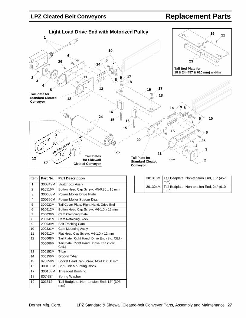
Light Load Drive End with Motorized Pulley
0311b
10
Tail Plate forStandard CleatedConveyor
Tail Platesfor Sidewall
Cleated Conveyor
1220
7
9 8
6 10
25
26
26
Item Part No. Part Description
1 300849M Switchbox Ass’y
2 910510M Button Head Cap Screw, M5-0.80 x 10 mm
3 300658M Power Moller Drive Plate
4 300660M Power Moller Spacer Disc
5 300032M Tail Cover Plate, Right Hand, Drive End
6 910612M Button Head Cap Screw, M6-1.0 x 12 mm
7 200038M Cam Clamping Plate
8 200341M Cam Retaining Block
9 200039M Belt Tracking Cam
10 200331M Cam Mounting Ass’y
11 930612M Flat Head Cap Screw, M6-1.0 x 12 mm
12 300068M Tail Plate, Right Hand, Drive End (Std. Cltd.)
300066M Tail Plate, Right Hand , Drive End (Sdw.Cltd.)
13 300152M T-bar
14 300150M Drop-In T-bar
15 920650M Socket Head Cap Screw, M6-1.0 x 50 mm
16 300155M Bed-Link Mounting Block
17 300158M Threaded Bushing
18 807-384 Spring Washer
19 301312 Tail Bedplate, Non-tension End, 12″ (305mm)
301318M Tail Bedplate, Non-tension End, 18″ (457mm)
301324M Tail Bedplate, Non-tension End, 24″ (610mm)
Replacement Parts LPZ Cleated Belt Conveyors
28 LPZ Standard & Sidewall Cleated-belt Conveyor Parts, Assembly and Maintenance Dorner Mfg. Corp.
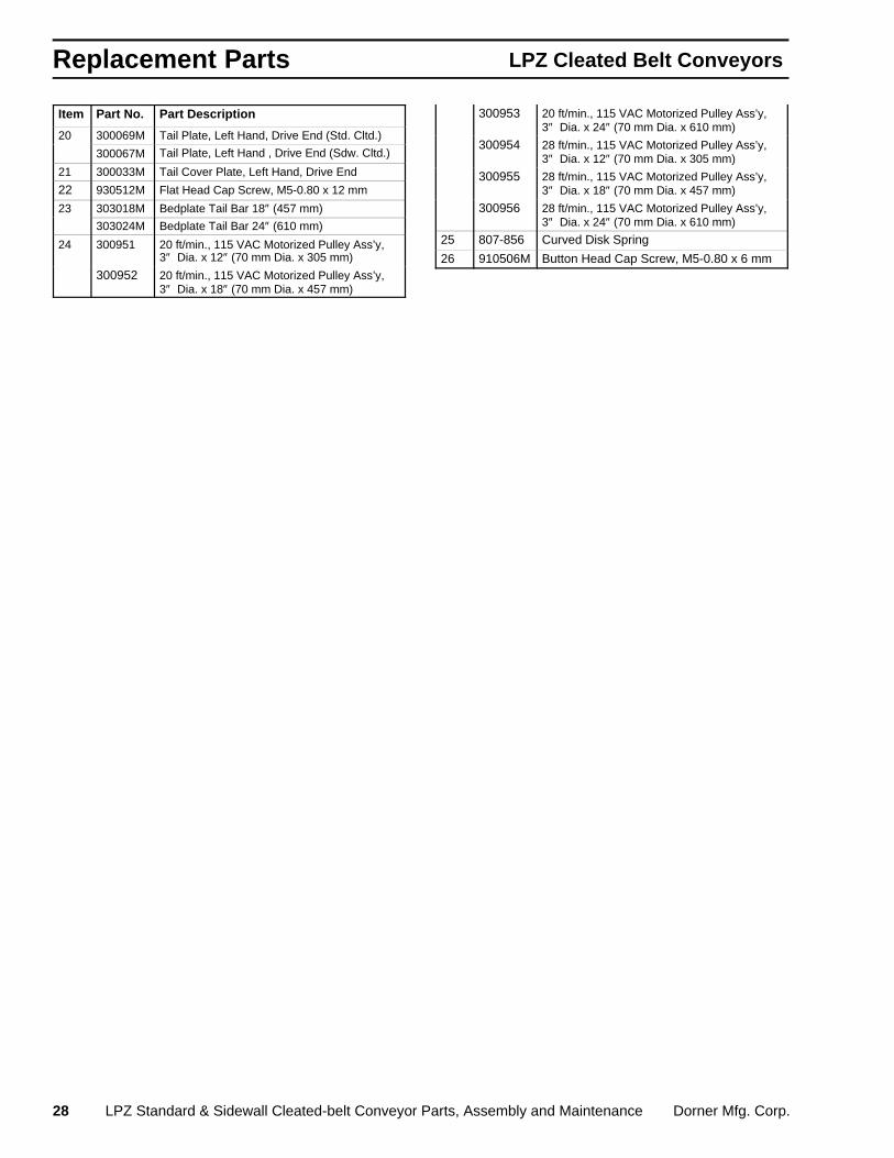
Item Part No. Part Description
20 300069M Tail Plate, Left Hand, Drive End (Std. Cltd.)
300067M Tail Plate, Left Hand , Drive End (Sdw. Cltd.)
21 300033M Tail Cover Plate, Left Hand, Drive End
22 930512M Flat Head Cap Screw, M5-0.80 x 12 mm
23 303018M Bedplate Tail Bar 18″ (457 mm)
303024M Bedplate Tail Bar 24″ (610 mm)
24 300951 20 ft/min., 115 VAC Motorized Pulley Ass’y,3″ Dia. x 12″ (70 mm Dia. x 305 mm)
300952 20 ft/min., 115 VAC Motorized Pulley Ass’y,3″ Dia. x 18″ (70 mm Dia. x 457 mm)
300953 20 ft/min., 115 VAC Motorized Pulley Ass’y,3″ Dia. x 24″ (70 mm Dia. x 610 mm)
300954 28 ft/min., 115 VAC Motorized Pulley Ass’y,3″ Dia. x 12″ (70 mm Dia. x 305 mm)
300955 28 ft/min., 115 VAC Motorized Pulley Ass’y,3″ Dia. x 18″ (70 mm Dia. x 457 mm)
300956 28 ft/min., 115 VAC Motorized Pulley Ass’y,3″ Dia. x 24″ (70 mm Dia. x 610 mm)
25 807-856 Curved Disk Spring
26 910506M Button Head Cap Screw, M5-0.80 x 6 mm

Replacement PartsLPZ Cleated Belt Conveyors
Dorner Mfg. Corp. LPZ Standard & Sidewall Cleated-belt Conveyor Parts, Assembly and Maintenance 29
Tail Plates forSidewall CleatedConveyor
1
2 3
4
5
6
3
7
910
11
12
13
14
1516
17
19
20
21
22
23
24
21 22
18
Drive End Tail Assembly
13
14
9
17
2016
9
Tail Bed Plate for18 & 24 (457 & 610 mm)widths
91011
12
PZ07
Tail Plates forStandard CleatedConveyor
8
8

Replacement Parts LPZ Cleated Belt Conveyors
30 LPZ Standard & Sidewall Cleated-belt Conveyor Parts, Assembly and Maintenance Dorner Mfg. Corp.
Item Part No. Part Description
1 300158M Threaded Bushing
2 807-384 Spring Washer
3 301308 Tail Bedplate, Non-tension End,8″ (203 mm)
301312 Tail Bedplate, Non-tension End,12″ (305 mm)
301318M Tail Bedplate, Non-tension End,18″ (457 mm)
301324M Tail Bedplate, Non-tension End,24″ (610 mm)
4 300155M Bed-Link Mounting Block
5 920650M Socket Head Cap Screw, M6-1.0 x 50 mm
6 930512M Flat Head Cap Screw, M5-0.80 x 12 mm
7 303018M Bedplate Tail Bar 18″ (457 mm)
303024M Bedplate Tail Bar 24″ (610 mm)
8 200331M Cam Mounting Ass’y
9 910612M Button Head Cap Screw, M6-1.0 x 12 mm
10 200038M Cam Clamping Plate
11 200341M Cam Retaining Block
12 200039M Belt Tracking Cam
13 300150M Drop-In T-bar
Item Part No. Part Description
14 300152M T-bar
15 300139M Drive Bearing Shaft Cover
16 910506M Button Head Cap Screw, M5-0.80 x 6 mm
17 930612M Flat Head Cap Screw, M6-1.0 x 12 mm
18 910508M Button Head Cap Screw, M5-0.80 x 8 mm
19 300032M Tail Cover Plate, Right Hand, Drive End
20 300146 Bearing Ass’y
21 300068M Tail Plate, Right Hand, Drive End, LowSide(Standard Cltd.)
300066M Tail Plate, Right Hand, Drive End, HighSide(Sidewall Cltd.)
22 300069M Tail Plate, Left Hand, Drive End, Low Side(Standard Cltd.)
300067M Tail Plate, Left Hand, Drive End, High Side(Sidewall Cltd.)
23 300033M Tail Cover Plate, Left Hand, Drive End
24 307308M Drive Pulley 8″ (203 mm) (19 mm Shaft)
307312M Drive Pulley 12″ (305 mm) (19 mm Shaft)
307318M Drive Pulley 18″ (457 mm) (19 mm Shaft)
307324M Drive Pulley 24″ (610 mm) (19 mm Shaft)

Replacement PartsLPZ Cleated Belt Conveyors
Dorner Mfg. Corp. LPZ Standard & Sidewall Cleated-belt Conveyor Parts, Assembly and Maintenance 31
Tension End Tail Assembly
1
171819
20
2
3
3
6
7
4
4
5
1718
19 2017
28
23
27
24
33
25
27
28
17
21
2221
22
8
8
15
9
10
11
12
13
14
Tail Plates for Sidewall Cleated Conveyors
Rack &PinionAssembly
24
25
9
26
PZ08
Tail Platesfor StandardCleated Conveyors
Tail Bed Plate for18 & 24 (457 & 610 mm)widths
16
16
29
30
31
32

Replacement Parts LPZ Cleated Belt Conveyors
32 LPZ Standard & Sidewall Cleated-belt Conveyor Parts, Assembly and Maintenance Dorner Mfg. Corp.
Item Part No. Part Description 1 300158M Threaded Bushing
2 807-384 Spring Washer
3 301708 Tail Bedplate, Tension End, 8″ (203 mm)
301712 Tail Bedplate, Tension End, 12″ (305 mm)
301718M Tail Bedplate, Tension End, 18″ (457 mm)
301724M Tail Bedplate, Tension End, 24″ (610 mm)
4 300155M Bed-Link Mounting Block
5 920650M Socket Head Cap Screw, M6-1.0 x 50 mm
6 930512M Flat Head Cap Screw, M5-0.80 x 12 mm
7 303018M Bedplate Tail Bar 18″ (457 mm)
303024M Bedplate Tail Bar 24″ (610 mm)
8 920508M Socket Head Cap Screw, M5-0.80 x 8 mm
9 300169M Rack and Pinion Housing Ass’y
10 200034 Pinion Wear Ring
11 200151 Back Bowed Spring
12 300166M Take-up Rack Housing
13 300167 Rack Gear
14 300168 Wear Rack Strip
15 203008M Pinion Gear 8″ (203 mm)
203012M Pinion Gear 12″ (305 mm)
203018M Pinion Gear 18″ (457 mm)
203024M Pinion Gear 24″ (610 mm)
16 200331M Cam Mounting Ass’y
17 910612M Button Head Cap Screw, M6-1.0 x 12 mm
18 200038M Cam Clamping Plate
19 200341M Cam Retaining Block
20 200039M Belt Tracking Cam
21 300150M Drop-In T-bar
Item Part No. Part Description
22 300152M T-bar
23 300028M Tail Cover Plate, Right Hand, 3″ (70 mm)
24 300060M Tail Plate, Right Hand, 3″ (70 mm), Low Side,(Standard Cleated)
300058M Tail Plate, Right Hand, 3″ (70 mm), High Side(Sidewall Cleated)
25 300061M Tail Plate, Left Hand, 3″ (70 mm), Low Side(Standard Cleated)
300059M Tail Plate, Left Hand, 3″ (70 mm), High Side(Sidewall Cleated)
26 300029M Tail Cover Plate, Left Hand, 3″ (70 mm)
27 930612M Flat Head Cap Screw, M6-1.0 x 12 mm
28 910506M Button Head Cap Screw, M5-0.80 x 6 mm
29 306708 Idler Pulley Ass’y 8″ (203 mm)
306712 Idler Pulley Ass’y 12″ (305 mm)
306718 Idler Pulley Ass’y 18″ (457 mm)
306724 Idler Pulley Ass’y 24″ (610 mm)
30 326608 Aluminum Pulley Tube, 8″ (203 mm)
326612 Aluminum Pulley Tube, 12″ (305 mm)
326618 Aluminum Pulley Tube, 18″ (457 mm)
326624 Aluminum Pulley Tube, 24″ (610 mm)
31 802-110 Ball Bearing (Set Screws Removed)
32 915-051 Retaining Ring
33 301908 Idler Shaft 8″ (203 mm) Wide
301912 Idler Shaft 12″ (305 mm) Wide
301918 Idler Shaft 18″ (457 mm) Wide
301924 Idler Shaft 24″ (610 mm) Wide
Replacement PartsLPZ Cleated Belt Conveyors
Dorner Mfg. Corp. LPZ Standard & Sidewall Cleated-belt Conveyor Parts, Assembly and Maintenance 33
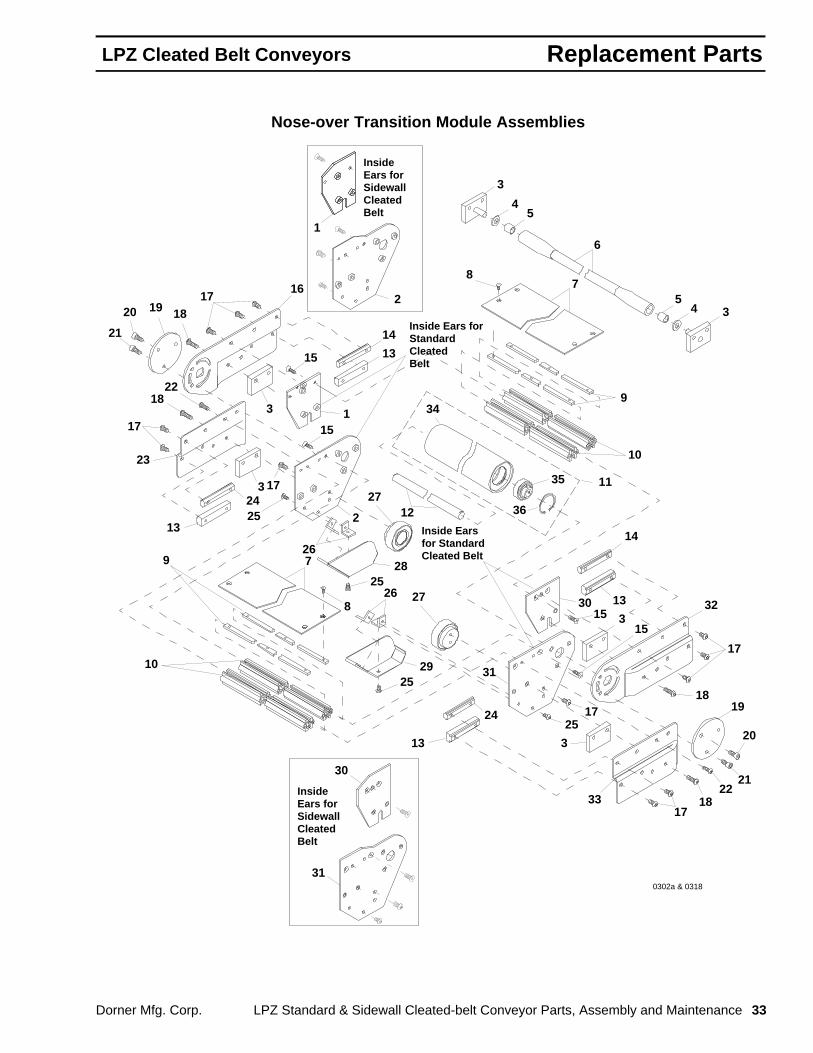
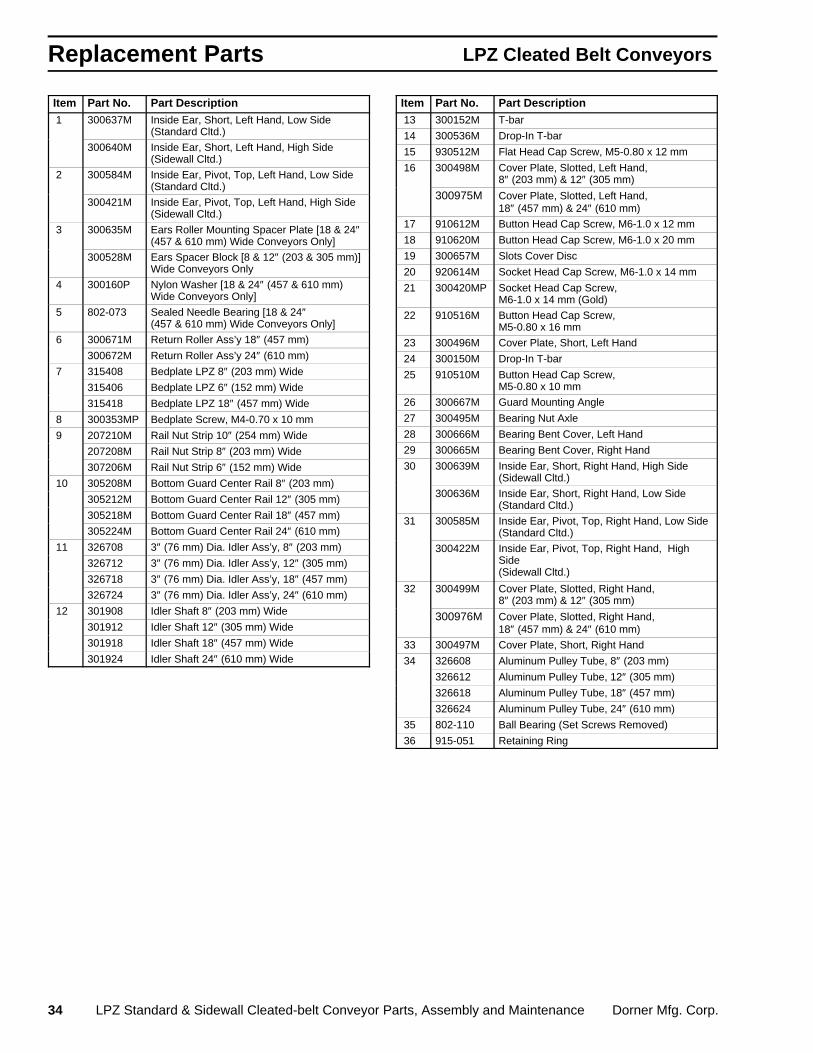
Nose-over Transition Module Assemblies
InsideEars forSidewallCleatedBelt
Inside Earsfor StandardCleated Belt
Inside Ears forStandardCleatedBelt
InsideEars forSidewallCleatedBelt
1
2 16
18 17
19 20
21
22 18
17
23
13
24 3
3
15
14
13
15
17
25
1
3
3
4 5
5 4
6
7
7 26
25
8
27 11
9
10
9
10
8
12
28
29 25
13
24
27 26
30
31
14
13 30 15
32
17
19 18
20
17
21 22
18
3
3
25 17
15
33
2
31
0302a & 0318
36
34
35
Replacement Parts LPZ Cleated Belt Conveyors
34 LPZ Standard & Sidewall Cleated-belt Conveyor Parts, Assembly and Maintenance Dorner Mfg. Corp.
Item Part No. Part Description 1 300637M Inside Ear, Short, Left Hand, Low Side
(Standard Cltd.)
300640M Inside Ear, Short, Left Hand, High Side(Sidewall Cltd.)
2 300584M Inside Ear, Pivot, Top, Left Hand, Low Side(Standard Cltd.)
300421M Inside Ear, Pivot, Top, Left Hand, High Side(Sidewall Cltd.)
3 300635M Ears Roller Mounting Spacer Plate [18 & 24″(457 & 610 mm) Wide Conveyors Only]
300528M Ears Spacer Block [8 & 12″ (203 & 305 mm)]Wide Conveyors Only
4 300160P Nylon Washer [18 & 24″ (457 & 610 mm)Wide Conveyors Only]
5 802-073 Sealed Needle Bearing [18 & 24″(457 & 610 mm) Wide Conveyors Only]
6 300671M Return Roller Ass’y 18″ (457 mm)
300672M Return Roller Ass’y 24″ (610 mm)
7 315408 Bedplate LPZ 8″ (203 mm) Wide
315406 Bedplate LPZ 6″ (152 mm) Wide
315418 Bedplate LPZ 18″ (457 mm) Wide
8 300353MP Bedplate Screw, M4-0.70 x 10 mm
9 207210M Rail Nut Strip 10″ (254 mm) Wide
207208M Rail Nut Strip 8″ (203 mm) Wide
307206M Rail Nut Strip 6″ (152 mm) Wide
10 305208M Bottom Guard Center Rail 8″ (203 mm)
305212M Bottom Guard Center Rail 12″ (305 mm)
305218M Bottom Guard Center Rail 18″ (457 mm)
305224M Bottom Guard Center Rail 24″ (610 mm)
11 326708 3″ (76 mm) Dia. Idler Ass’y, 8″ (203 mm)
326712 3″ (76 mm) Dia. Idler Ass’y, 12″ (305 mm)
326718 3″ (76 mm) Dia. Idler Ass’y, 18″ (457 mm)
326724 3″ (76 mm) Dia. Idler Ass’y, 24″ (610 mm)
12 301908 Idler Shaft 8″ (203 mm) Wide
301912 Idler Shaft 12″ (305 mm) Wide
301918 Idler Shaft 18″ (457 mm) Wide
301924 Idler Shaft 24″ (610 mm) Wide
Item Part No. Part Description 13 300152M T-bar
14 300536M Drop-In T-bar
15 930512M Flat Head Cap Screw, M5-0.80 x 12 mm
16 300498M Cover Plate, Slotted, Left Hand,8″ (203 mm) & 12″ (305 mm)
300975M Cover Plate, Slotted, Left Hand,18″ (457 mm) & 24″ (610 mm)
17 910612M Button Head Cap Screw, M6-1.0 x 12 mm
18 910620M Button Head Cap Screw, M6-1.0 x 20 mm
19 300657M Slots Cover Disc
20 920614M Socket Head Cap Screw, M6-1.0 x 14 mm
21 300420MP Socket Head Cap Screw,M6-1.0 x 14 mm (Gold)
22 910516M Button Head Cap Screw,M5-0.80 x 16 mm
23 300496M Cover Plate, Short, Left Hand
24 300150M Drop-In T-bar
25 910510M Button Head Cap Screw,M5-0.80 x 10 mm
26 300667M Guard Mounting Angle
27 300495M Bearing Nut Axle
28 300666M Bearing Bent Cover, Left Hand
29 300665M Bearing Bent Cover, Right Hand
30 300639M Inside Ear, Short, Right Hand, High Side(Sidewall Cltd.)
300636M Inside Ear, Short, Right Hand, Low Side(Standard Cltd.)
31 300585M Inside Ear, Pivot, Top, Right Hand, Low Side(Standard Cltd.)
300422M Inside Ear, Pivot, Top, Right Hand, HighSide(Sidewall Cltd.)
32 300499M Cover Plate, Slotted, Right Hand,8″ (203 mm) & 12″ (305 mm)
300976M Cover Plate, Slotted, Right Hand,18″ (457 mm) & 24″ (610 mm)
33 300497M Cover Plate, Short, Right Hand
34 326608 Aluminum Pulley Tube, 8″ (203 mm)
326612 Aluminum Pulley Tube, 12″ (305 mm)
326618 Aluminum Pulley Tube, 18″ (457 mm)
326624 Aluminum Pulley Tube, 24″ (610 mm)
35 802-110 Ball Bearing (Set Screws Removed)
36 915-051 Retaining Ring

Replacement PartsLPZ Cleated Belt Conveyors
Dorner Mfg. Corp. LPZ Standard & Sidewall Cleated-belt Conveyor Parts, Assembly and Maintenance 35
1
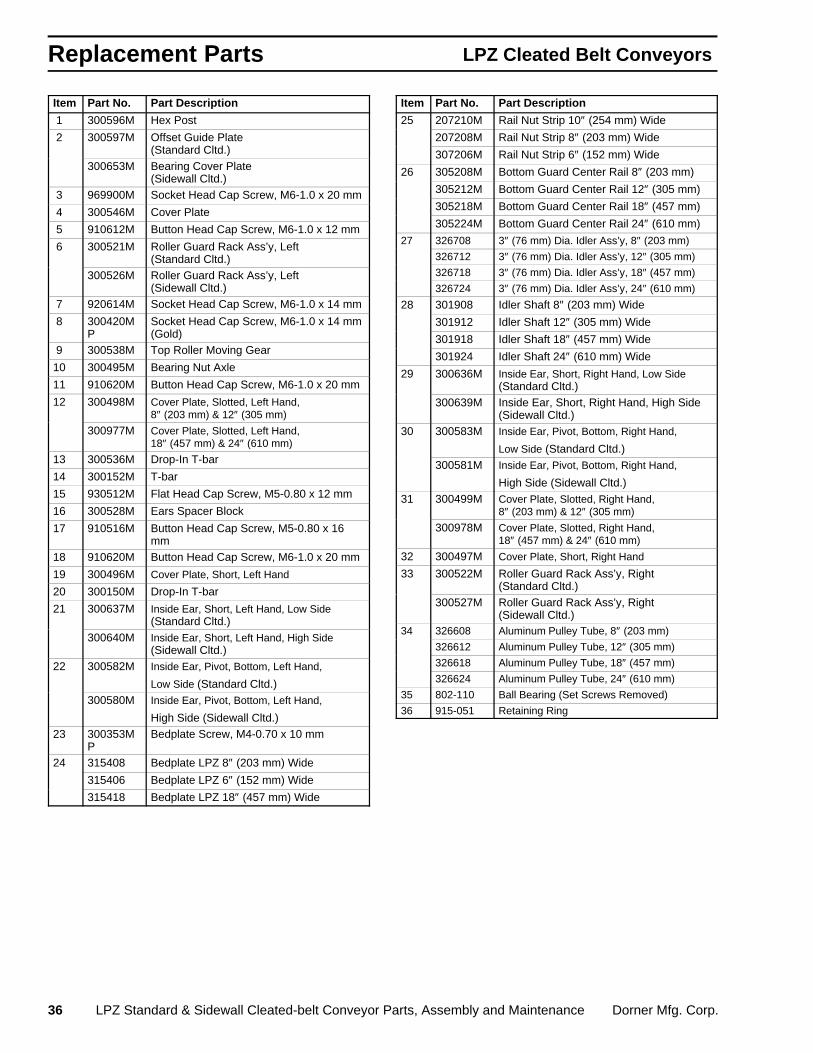
Horizontal to Incline Transition Module Assemblies
Parts forStandardCleatedBelt
Plates forSidewall
Cleated Belt
Parts forStandardCleatedBelt
Parts for Sidewall
Cleated Belt
Parts forStandard
Cleated Belt
Parts forStandard
Cleated Belt
1
1
1
1
1
3
3
5
5
6 7
8 9 10 11
5
12
2 23
1718
19
1620
15
1314
21
22
24
2325
26
20
30
32
31
2
2
2
3
4
5
5
4
5
5
5
6
7 8
9
1011
13
14
14
14
15
15
15
16
16
16
17
18
24
25
26
27
28
29
29
30
33
33
21
22
0303a & 0304a
36
34
35
Replacement Parts LPZ Cleated Belt Conveyors
36 LPZ Standard & Sidewall Cleated-belt Conveyor Parts, Assembly and Maintenance Dorner Mfg. Corp.
Item Part No. Part Description
1 300596M Hex Post
2 300597M Offset Guide Plate(Standard Cltd.)
300653M Bearing Cover Plate(Sidewall Cltd.)
3 969900M Socket Head Cap Screw, M6-1.0 x 20 mm
4 300546M Cover Plate
5 910612M Button Head Cap Screw, M6-1.0 x 12 mm
6 300521M Roller Guard Rack Ass’y, Left(Standard Cltd.)
300526M Roller Guard Rack Ass’y, Left(Sidewall Cltd.)
7 920614M Socket Head Cap Screw, M6-1.0 x 14 mm
8 300420MP
Socket Head Cap Screw, M6-1.0 x 14 mm(Gold)
9 300538M Top Roller Moving Gear
10 300495M Bearing Nut Axle
11 910620M Button Head Cap Screw, M6-1.0 x 20 mm
12 300498M Cover Plate, Slotted, Left Hand,8″ (203 mm) & 12″ (305 mm)
300977M Cover Plate, Slotted, Left Hand,18″ (457 mm) & 24″ (610 mm)
13 300536M Drop-In T-bar
14 300152M T-bar
15 930512M Flat Head Cap Screw, M5-0.80 x 12 mm
16 300528M Ears Spacer Block
17 910516M Button Head Cap Screw, M5-0.80 x 16mm
18 910620M Button Head Cap Screw, M6-1.0 x 20 mm
19 300496M Cover Plate, Short, Left Hand
20 300150M Drop-In T-bar
21 300637M Inside Ear, Short, Left Hand, Low Side(Standard Cltd.)
300640M Inside Ear, Short, Left Hand, High Side(Sidewall Cltd.)
22 300582M Inside Ear, Pivot, Bottom, Left Hand,
Low Side (Standard Cltd.)300580M Inside Ear, Pivot, Bottom, Left Hand,
High Side (Sidewall Cltd.)23 300353M
PBedplate Screw, M4-0.70 x 10 mm
24 315408 Bedplate LPZ 8″ (203 mm) Wide
315406 Bedplate LPZ 6″ (152 mm) Wide
315418 Bedplate LPZ 18″ (457 mm) Wide
Item Part No. Part Description
25 207210M Rail Nut Strip 10″ (254 mm) Wide
207208M Rail Nut Strip 8″ (203 mm) Wide
307206M Rail Nut Strip 6″ (152 mm) Wide
26 305208M Bottom Guard Center Rail 8″ (203 mm)
305212M Bottom Guard Center Rail 12″ (305 mm)
305218M Bottom Guard Center Rail 18″ (457 mm)
305224M Bottom Guard Center Rail 24″ (610 mm)
27 326708 3″ (76 mm) Dia. Idler Ass’y, 8″ (203 mm)
326712 3″ (76 mm) Dia. Idler Ass’y, 12″ (305 mm)
326718 3″ (76 mm) Dia. Idler Ass’y, 18″ (457 mm)
326724 3″ (76 mm) Dia. Idler Ass’y, 24″ (610 mm)
28 301908 Idler Shaft 8″ (203 mm) Wide
301912 Idler Shaft 12″ (305 mm) Wide
301918 Idler Shaft 18″ (457 mm) Wide
301924 Idler Shaft 24″ (610 mm) Wide
29 300636M Inside Ear, Short, Right Hand, Low Side(Standard Cltd.)
300639M Inside Ear, Short, Right Hand, High Side(Sidewall Cltd.)
30 300583M Inside Ear, Pivot, Bottom, Right Hand,
Low Side (Standard Cltd.)300581M Inside Ear, Pivot, Bottom, Right Hand,
High Side (Sidewall Cltd.)31 300499M Cover Plate, Slotted, Right Hand,
8″ (203 mm) & 12″ (305 mm)
300978M Cover Plate, Slotted, Right Hand,18″ (457 mm) & 24″ (610 mm)
32 300497M Cover Plate, Short, Right Hand
33 300522M Roller Guard Rack Ass’y, Right(Standard Cltd.)
300527M Roller Guard Rack Ass’y, Right(Sidewall Cltd.)
34 326608 Aluminum Pulley Tube, 8″ (203 mm)
326612 Aluminum Pulley Tube, 12″ (305 mm)
326618 Aluminum Pulley Tube, 18″ (457 mm)
326624 Aluminum Pulley Tube, 24″ (610 mm)
35 802-110 Ball Bearing (Set Screws Removed)
36 915-051 Retaining Ring

Replacement PartsLPZ Cleated Belt Conveyors
Dorner Mfg. Corp. LPZ Standard & Sidewall Cleated-belt Conveyor Parts, Assembly and Maintenance 37
Standard Cleated Belt Conveyor Guiding
A
B
C
C
D
E
Item X 910618M M6 x 18 mm Button Head Cap ScrewItem Y 200121 Guide Retaining ClipItem Z 639971M Single Drop-in T-bar
IncliningBelt
Travel
DecliningBelt
Travel
XX
YZY Z
0359
0313
Section LengthTail Section Intermediate
SectionTransition Section with
Inclining Belt TravelTransition Section withDeclining Belt Travel
“ L ” “ A ” “ B ” “ C ” “ D ” “ E ” “ D ” “ E ”
2 ft (610 mm) None None None 382041 382040 382158 3821593 ft (915 mm) 382015 382014 None 382019 382018 382020 3820214 ft (1220 mm) 382017 382016 None 382019 382018 382020 3820215 ft (1525 mm) 382015 382014 382074 382019 382018 382020 3820216 ft (1830 mm) 382017 382016 382074 382019 382018 382020 3820217 ft (2135 mm) 382015 382014 382075 382019 382018 382020 3820218 ft (2440 mm) 382017 382016 382075 382019 382018 382020 3820219 ft (2745 mm) 382015 382014 382076 382019 382018 382020 38202110 ft (3050 mm) 382017 382016 382076 382019 382018 382020 38202111 ft (3355 mm) 382015 382014 382077 382019 382018 382020 38202112 ft (3660 mm) 382017 382016 382077 382019 382018 382020 38202113 ft (3965 mm) 382015 382014 382078 382019 382018 382020 382021
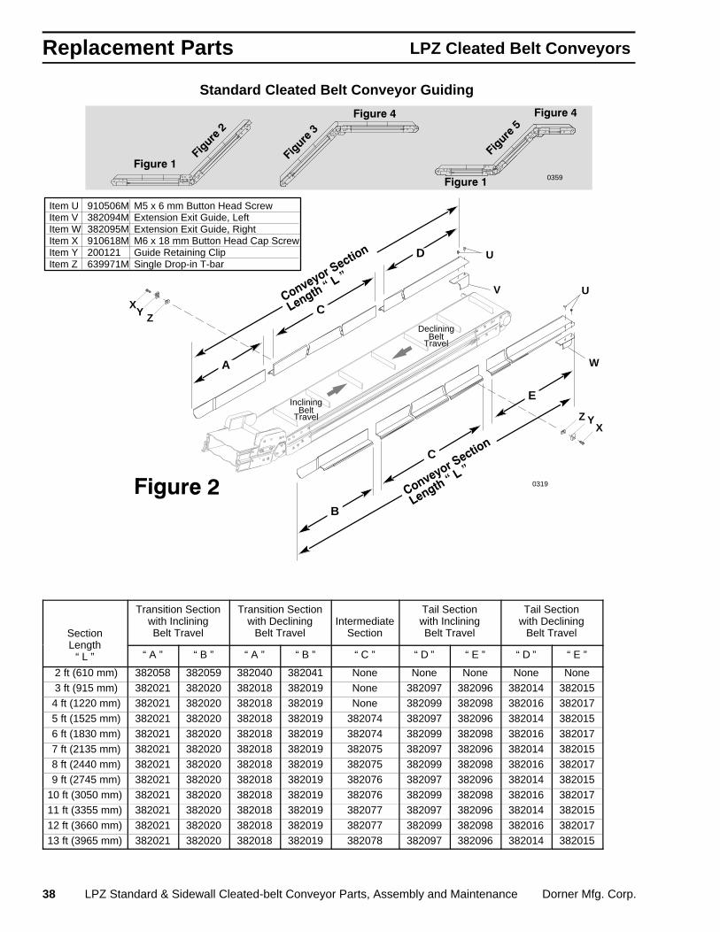
Replacement Parts LPZ Cleated Belt Conveyors
38 LPZ Standard & Sidewall Cleated-belt Conveyor Parts, Assembly and Maintenance Dorner Mfg. Corp.
Standard Cleated Belt Conveyor Guiding
A
B
C
C
D
E
X
XYZ
Y Z
U
V
W
U
Item U 910506M M5 x 6 mm Button Head ScrewItem V 382094M Extension Exit Guide, LeftItem W 382095M Extension Exit Guide, RightItem X 910618M M6 x 18 mm Button Head Cap ScrewItem Y 200121 Guide Retaining ClipItem Z 639971M Single Drop-in T-bar
IncliningBelt
Travel
DecliningBelt
Travel
0319
0359
Section
Transition Sectionwith IncliningBelt Travel
Transition Sectionwith Declining
Belt TravelIntermediate
Section
Tail Sectionwith IncliningBelt Travel
Tail Sectionwith Declining
Belt TravelLength
“ L ” “ A ” “ B ” “ A ” “ B ” “ C ” “ D ” “ E ” “ D ” “ E ”
2 ft (610 mm) 382058 382059 382040 382041 None None None None None 3 ft (915 mm) 382021 382020 382018 382019 None 382097 382096 382014 382015 4 ft (1220 mm) 382021 382020 382018 382019 None 382099 382098 382016 382017 5 ft (1525 mm) 382021 382020 382018 382019 382074 382097 382096 382014 382015 6 ft (1830 mm) 382021 382020 382018 382019 382074 382099 382098 382016 382017 7 ft (2135 mm) 382021 382020 382018 382019 382075 382097 382096 382014 382015 8 ft (2440 mm) 382021 382020 382018 382019 382075 382099 382098 382016 382017 9 ft (2745 mm) 382021 382020 382018 382019 382076 382097 382096 382014 38201510 ft (3050 mm) 382021 382020 382018 382019 382076 382099 382098 382016 38201711 ft (3355 mm) 382021 382020 382018 382019 382077 382097 382096 382014 38201512 ft (3660 mm) 382021 382020 382018 382019 382077 382099 382098 382016 38201713 ft (3965 mm) 382021 382020 382018 382019 382078 382097 382096 382014 382015

Replacement PartsLPZ Cleated Belt Conveyors
Dorner Mfg. Corp. LPZ Standard & Sidewall Cleated-belt Conveyor Parts, Assembly and Maintenance 39
Standard Cleated Belt Conveyor Guiding
A
B
C
C
D
E
Item X 910618M M6 x 18 mm Button Head Cap ScrewItem Y 200121 Guide Retaining ClipItem Z 639971M Single Drop-in T-bar
XY Z
XY
ZInclining
BeltTravel
DecliningBelt
Travel
0320
0359
Section LengthTail Section Intermediate
SectionTransition Section with
Inclining Belt TravelTransition Section withDeclining Belt Travel
“ L ”“ A ” “ B ” “ C ” “ D ” “ E ” “ D ” “ E ”
2 ft (610 mm) None None None 382060 382061 382054 382055 3 ft (915 mm) 382015 382014 None 382035 382034 382038 382039 4 ft (1220 mm) 382017 382016 None 382035 382034 382038 382039 5 ft (1525 mm) 382015 382014 382074 382035 382034 382038 382039 6 ft (1830 mm) 382017 382016 382074 382035 382034 382038 382039 7 ft (2135 mm) 382015 382014 382075 382035 382034 382038 382039 8 ft (2440 mm) 382017 382016 382075 382035 382034 382038 382039 9 ft (2745 mm) 382015 382014 382076 382035 382034 382038 38203910 ft (3050 mm) 382017 382016 382076 382035 382034 382038 38203911 ft (3355 mm) 382015 382014 382077 382035 382034 382038 38203912 ft (3660 mm) 382017 382016 382077 382035 382034 382038 38203913 ft (3965 mm) 382015 382014 382078 382035 382034 382038 382039

Replacement Parts LPZ Cleated Belt Conveyors
40 LPZ Standard & Sidewall Cleated-belt Conveyor Parts, Assembly and Maintenance Dorner Mfg. Corp.
D
E
C
C
A
B
Item X 910618M M6 x 18 mm Button Head Cap ScrewItem Y 200121 Guide Retaining ClipItem Z 639971M Single Drop-in T-bar
IncliningBelt
Travel
DecliningBelt
Travel
XYZ
XY Z
Standard Cleated Belt Conveyor Guiding
0321
0359
Section LengthTransition Section with
Inclining Belt TravelTransition Section withDeclining Belt Travel
IntermediateSection Tail Section
“ L ”“ A ” “ B ” “ A ” “ B ” “ C ” “ D ” “ E ”
2 ft (610 mm) 382055 382054 382061 382060 None None None 3 ft (915 mm) 382039 382038 382034 382035 None 382015 382014 4 ft (1220 mm) 382039 382038 382034 382035 None 382017 382016 5 ft (1525 mm) 382039 382038 382034 382035 382074 382015 382014 6 ft (1830 mm) 382039 382038 382034 382035 382074 382017 382016 7 ft (2135 mm) 382039 382038 382034 382035 382075 382015 382014 8 ft (2440 mm) 382039 382038 382034 382035 382075 382017 382016 9 ft (2745 mm) 382039 382038 382034 382035 382076 382015 38201410 ft (3050 mm) 382039 382038 382034 382035 382076 382017 38201611 ft (3355 mm) 382039 382038 382034 382035 382077 382015 38201412 ft (3660 mm) 382039 382038 382034 382035 382077 382017 38201613 ft (3965 mm) 382039 382038 382034 382035 382078 382015 382014
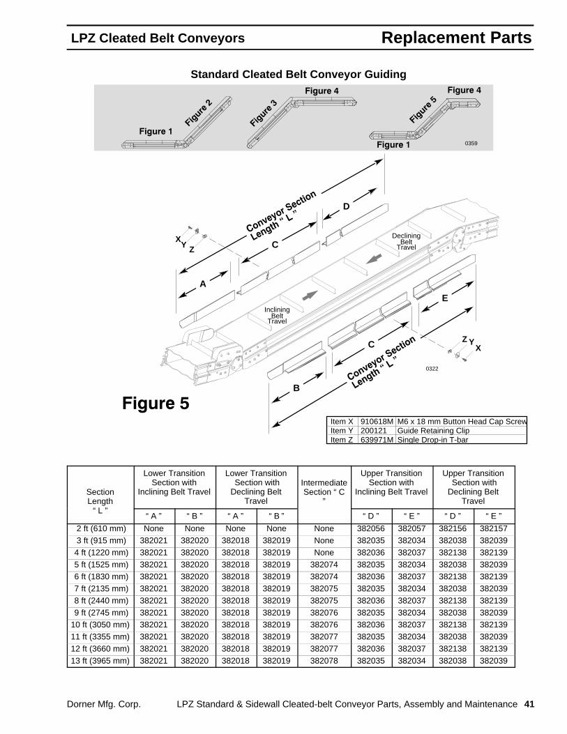
Replacement PartsLPZ Cleated Belt Conveyors
Dorner Mfg. Corp. LPZ Standard & Sidewall Cleated-belt Conveyor Parts, Assembly and Maintenance 41
A
B
C
C
D
E
Item X 910618M M6 x 18 mm Button Head Cap ScrewItem Y 200121 Guide Retaining ClipItem Z 639971M Single Drop-in T-bar
IncliningBelt
Travel
DecliningBelt
Travel
XYZ
XY Z
Standard Cleated Belt Conveyor Guiding
0322
0359
SectionLength
Lower TransitionSection with
Inclining Belt Travel
Lower Transition Section withDeclining Belt
Travel
IntermediateSection “ C
”
Upper TransitionSection with
Inclining Belt Travel
Upper Transition Section withDeclining Belt
Travel“ L ”
“ A ” “ B ” “ A ” “ B ” “ D ” “ E ” “ D ” “ E ”
2 ft (610 mm) None None None None None 382056 382057 382156 382157 3 ft (915 mm) 382021 382020 382018 382019 None 382035 382034 382038 382039 4 ft (1220 mm) 382021 382020 382018 382019 None 382036 382037 382138 382139 5 ft (1525 mm) 382021 382020 382018 382019 382074 382035 382034 382038 382039 6 ft (1830 mm) 382021 382020 382018 382019 382074 382036 382037 382138 382139 7 ft (2135 mm) 382021 382020 382018 382019 382075 382035 382034 382038 382039 8 ft (2440 mm) 382021 382020 382018 382019 382075 382036 382037 382138 382139 9 ft (2745 mm) 382021 382020 382018 382019 382076 382035 382034 382038 38203910 ft (3050 mm) 382021 382020 382018 382019 382076 382036 382037 382138 38213911 ft (3355 mm) 382021 382020 382018 382019 382077 382035 382034 382038 38203912 ft (3660 mm) 382021 382020 382018 382019 382077 382036 382037 382138 38213913 ft (3965 mm) 382021 382020 382018 382019 382078 382035 382034 382038 382039

Replacement Parts LPZ Cleated Belt Conveyors
42 LPZ Standard & Sidewall Cleated-belt Conveyor Parts, Assembly and Maintenance Dorner Mfg. Corp.
8 5
18
3
2
20
11
9
19
12
16
1 4
6
7
10
21
13
14
15
16
17
TaperLock
Assembly
17
14
Cleated Belt Bottom Mounting Package Exploded-view
0298
Note: Gearmotor is not in-cluded with mountingpackage. Square key isincluded with gearmo-tor. See page 45.
Item Part No. Part Description
1 980018M Square Key (Undersized), 6 mm x 18 mm
2 310046M Bottom Drive Cover (Cleated Belt)
3 910410M Button Head Cap Screw, M4-0.70 x 10 mm
4 300038M Spacer, 3/8 Thick
5 310035M Drive Bottom Mounting Plate (Cleated Belt)
6 300187 Idler Spacer Bar
7 300186M Idler Guide Bar
8 930625M Flat Head Cap Screw, M6-1.0 x 25 mm
9 628144M Cam Follower Nut
10 605284 Hard Washer, Black Oxide
11 802-059 Cam Follower Bearing
12 921250M Socket Head Cap Screw, M12-1.75 x 50mm
13 920625M Socket Head Cap Screw, M6-1.0 x 25 mm
14 920620M Socket Head Cap Screw, M6-1.0 x 20 mm
15 920630M Socket Head Cap Screw, M6-1.0 x 30 mm
Item Part No. Part Description
16 811-126 Pulley, 16 Tooth, Taper Lock , TL-1108 811-127 Pulley, 18 Tooth, Taper Lock , TL-1210 811-133 Pulley, 14 Tooth, Taper Lock , TL-1108 811-135 Pulley, 20 Tooth, Taper Lock , TL-1210 811-136 Pulley, 22 Tooth, Taper Lock , TL-1610 811-137 Pulley, 24 Tooth, Taper Lock , TL-161017 811-206 Taper Lock Bushing, TL-1610, 19 mm
Bore 811-205 Taper Lock Bushing, TL-1210, 19 mm
Bore 811-204 Taper Lock Bushing, TL-1108, 19 mm
Bore18 300049M Drive Pulley, 19 Tooth, 19 mm Bore19 970608M Socket Head Set Screw, M6-1.0 x 8 mm20 814-059 Timing Belt, 27″ (685 mm) Long 814-060 Timing Belt, 28″ (711 mm) Long21 920616M Socket Head Cap Screw, M6-1.0 x 16 mm
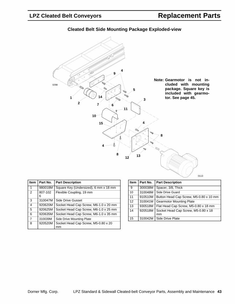
Replacement PartsLPZ Cleated Belt Conveyors
Dorner Mfg. Corp. LPZ Standard & Sidewall Cleated-belt Conveyor Parts, Assembly and Maintenance 43
Cleated Belt Side Mounting Package Exploded-view
7
5
2
12
11
4
1
9
13
14
15
6
10
4
8
4
8
3
0113
0298
Note: Gearmotor is not in-cluded with mountingpackage. Square key isincluded with gearmo-tor. See page 45.
Item Part No. Part Description
1 980018M Square Key (Undersized), 6 mm x 18 mm 2 807-102
6Flexible Coupling, 19 mm
3 310047M Side Drive Gusset 4 920620M Socket Head Cap Screw, M6-1.0 x 20 mm 5 920625M Socket Head Cap Screw, M6-1.0 x 25 mm 6 920635M Socket Head Cap Screw, M6-1.0 x 35 mm
7 310039M Side Drive Mounting Plate 8 920520M Socket Head Cap Screw, M5-0.80 x 20
mm
Item Part No. Part Description
9 300038M Spacer, 3/8, Thick10 310048M Side Drive Guard
11 910510M Button Head Cap Screw, M5-0.80 x 10 mm12 310041M Gearmotor Mounting Plate13 930518M Flat Head Cap Screw, M5-0.80 x 18 mm14 920518M Socket Head Cap Screw, M5-0.80 x 18
mm15 310042M Side Drive Plate

Replacement Parts LPZ Cleated Belt Conveyors
44 LPZ Standard & Sidewall Cleated-belt Conveyor Parts, Assembly and Maintenance Dorner Mfg. Corp.
Cleated Belt Top Mounting Package Exploded-view
8
5
18
3
2
20
11
9
19
12
17
Taper Lock Assembly
16
1 4
6
7
10
21
13
1415
16
17
14
0112
0298
Note: Gearmotor is not in-cluded with mountingpackage. Square key isincluded with gearmo-tor. See page 45.
Item Part No. Part Description
1 980018M Square Key (Undersided), 6 mm x 18 mm
2 310046M Top Drive Cover
3 910410M Button Head Cap Screw, M4-0.70 x 10 mm
4 300038M Spacer, 3/8 Thick
5 310045M Drive Top Mounting Plate
6 300187 Idler Spacer Bar
7 300186M Idler Guide Bar
8 930625M Flat Head Cap Screw, M5-1.0 x 25 mm
9 628144M Cam Follower Nut
10 605284 Hard Washer, Black Oxide
11 802-059 Cam Follower Bearing
12 921250M Socket Head Cap Screw, M12-1.75 x 50mm
13 920625M Socket Head Cap Screw, M6-1.0 x 25 mm
14 920620M Socket Head Cap Screw, M6-1.0 x 20 mm
15 920630M Socket Head Cap Screw, M6-1.0 x 30 mm
Item Part No. Part Description
16 811-126 Pulley, 16 Tooth, Taper Lock , TL-1108 811-127 Pulley, 18 Tooth, Taper Lock , TL-1210 811-133 Pulley, 14 Tooth, Taper Lock , TL-1108 811-135 Pulley, 20 Tooth, Taper Lock , TL-1210 811-136 Pulley, 22 Tooth, Taper Lock , TL-1610 811-137 Pulley, 24 Tooth, Taper Lock , TL-161017 811-206 Taper Lock Bushing, TL-1610, 19 mm
Bore 811-205 Taper Lock Bushing, TL-1210, 19 mm
Bore 811-204 Taper Lock Bushing, TL-1108, 19 mm
Bore18 300049M Drive Pulley, 19 Tooth, 19 mm Bore19 970608M Socket Head Set Screw, M6-1.0 x 8 mm20 814-059 Timing Belt, 27″ (685 mm) Long 814-060 Timing Belt, 28″ (711 mm) Long21 920616M Socket Head Cap Screw, M6-1.0 x 16 mm
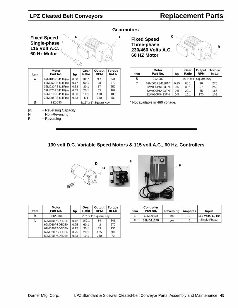
Replacement PartsLPZ Cleated Belt Conveyors
Dorner Mfg. Corp. LPZ Standard & Sidewall Cleated-belt Conveyor Parts, Assembly and Maintenance 45
Gearmotors
Fixed SpeedSingle-phase115 Volt A.C.60 Hz Motor
BA
ItemMotor
Part No. hpGearRatio
OutputRPM
TorqueIn-Lb
A 62M180PS411F(n) 0.08 180:1 9.4 34162M060PS411F(n) 0.17 60:1 28 27032M030PS411F(n) 0.33 30:1 57 25032M020PS411F(n) 0.33 20:1 85 16732M010PS411F(n) 0.33 10:1 170 10832M005PS411F(n) 0.33 5:1 340 56
B 912-080 3/16″ x 1″ Square Key
(n) = Reversing CapacityN = Non-ReversingR = Reversing
Fixed SpeedThree-phase230/460 Volts A.C.60 HZ Motor
B
C
ItemMotor
Part No. hpGearRatio
OutputRPM
TorqueIn-Lb
B 912-080 3/16″ x 1″ Square Key
C 62M060PS423FN* 0.25 60:1 28 27032M030PS423FN 0.5 30:1 57 25032M020PS423FN 0.5 20:1 85 16732M010PS423FN 0.5 10:1 170 108
* Not available in 460 voltage.
130 volt D.C. Variable Speed Motors & 115 volt A.C., 60 Hz. Controllers
BD
EF
ItemMotor
Part No. hpGearRatio
OutputRPM
TorqueIn-Lb
B 912-080 3/16″ x 1″ Square Key
D 62M180PSD3DEN 0.12 180:1 14 34162M060PSD3DEN 0.25 60:1 42 27062M030PSD3DEN 0.25 30:1 83 13562M020PSD3DEN 0.25 20:1 125 9062M010PSD3DEN 0.33 10:1 250 72
ItemControllerPart No. Reversing Amperes Input
E 62MD1134 no 3 115 Volts, 60 Hz
F 62MD1134R yes 5
115 Volts, 60 HzSingle Phase
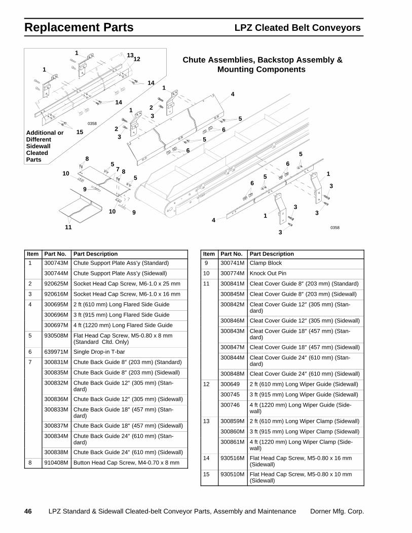
Replacement Parts LPZ Cleated Belt Conveyors
46 LPZ Standard & Sidewall Cleated-belt Conveyor Parts, Assembly and Maintenance Dorner Mfg. Corp.
5 7
Additional or DifferentSidewall CleatedParts
Chute Assemblies, Backstop Assembly &Mounting Components
1 4
2 3 5
6
5
10
9
11 4
910
8
6
5 3 2
3
3
3
3
1
1
1
6
6
5
5
1213
1
1
14
14
15
8
0358
0358
Item Part No. Part Description
1 300743M Chute Support Plate Ass’y (Standard)
300744M Chute Support Plate Ass’y (Sidewall)
2 920625M Socket Head Cap Screw, M6-1.0 x 25 mm
3 920616M Socket Head Cap Screw, M6-1.0 x 16 mm
4 300695M 2 ft (610 mm) Long Flared Side Guide
300696M 3 ft (915 mm) Long Flared Side Guide
300697M 4 ft (1220 mm) Long Flared Side Guide
5 930508M Flat Head Cap Screw, M5-0.80 x 8 mm(Standard Cltd. Only)
6 639971M Single Drop-in T-bar
7 300831M Chute Back Guide 8″ (203 mm) (Standard)
300835M Chute Back Guide 8″ (203 mm) (Sidewall)
300832M Chute Back Guide 12″ (305 mm) (Stan-dard)
300836M Chute Back Guide 12″ (305 mm) (Sidewall)
300833M Chute Back Guide 18″ (457 mm) (Stan-dard)
300837M Chute Back Guide 18″ (457 mm) (Sidewall)
300834M Chute Back Guide 24″ (610 mm) (Stan-dard)
300838M Chute Back Guide 24″ (610 mm) (Sidewall)
8 910408M Button Head Cap Screw, M4-0.70 x 8 mm
Item Part No. Part Description
9 300741M Clamp Block
10 300774M Knock Out Pin
11 300841M Cleat Cover Guide 8″ (203 mm) (Standard)
300845M Cleat Cover Guide 8″ (203 mm) (Sidewall)
300842M Cleat Cover Guide 12″ (305 mm) (Stan-dard)
300846M Cleat Cover Guide 12″ (305 mm) (Sidewall)
300843M Cleat Cover Guide 18″ (457 mm) (Stan-dard)
300847M Cleat Cover Guide 18″ (457 mm) (Sidewall)
300844M Cleat Cover Guide 24″ (610 mm) (Stan-dard)
300848M Cleat Cover Guide 24″ (610 mm) (Sidewall)
12 300649 2 ft (610 mm) Long Wiper Guide (Sidewall)
300745 3 ft (915 mm) Long Wiper Guide (Sidewall)
300746 4 ft (1220 mm) Long Wiper Guide (Side-wall)
13 300859M 2 ft (610 mm) Long Wiper Clamp (Sidewall)
300860M 3 ft (915 mm) Long Wiper Clamp (Sidewall)
300861M 4 ft (1220 mm) Long Wiper Clamp (Side-wall)
14 930516M Flat Head Cap Screw, M5-0.80 x 16 mm(Sidewall)
15 930510M Flat Head Cap Screw, M5-0.80 x 10 mm(Sidewall)
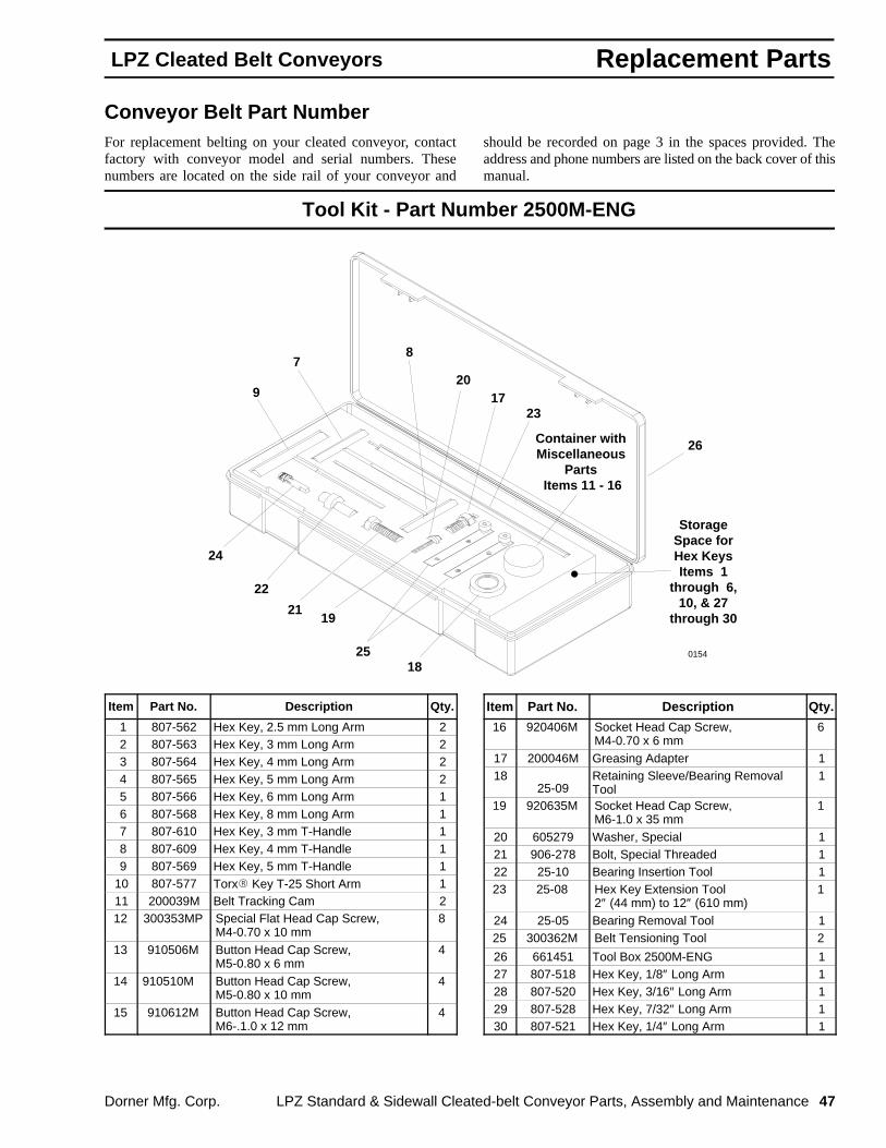
Replacement PartsLPZ Cleated Belt Conveyors
Dorner Mfg. Corp. LPZ Standard & Sidewall Cleated-belt Conveyor Parts, Assembly and Maintenance 47
Conveyor Belt Part NumberFor replacement belting on your cleated conveyor, contactfactory with conveyor model and serial numbers. Thesenumbers are located on the side rail of your conveyor and
should be recorded on page 3 in the spaces provided. Theaddress and phone numbers are listed on the back cover of thismanual.
Tool Kit - Part Number 2500M-ENG
0154
StorageSpace forHex KeysItems 1
through 6,10, & 27
through 30
7 8
9
22
23
24
25
26
17
18
19
20
21
Container withMiscellaneous
Parts Items 11 - 16
Item Part No. Description Qty.
1 807-562 Hex Key, 2.5 mm Long Arm 2 2 807-563 Hex Key, 3 mm Long Arm 2 3 807-564 Hex Key, 4 mm Long Arm 2 4 807-565 Hex Key, 5 mm Long Arm 2 5 807-566 Hex Key, 6 mm Long Arm 1 6 807-568 Hex Key, 8 mm Long Arm 1 7 807-610 Hex Key, 3 mm T-Handle 1 8 807-609 Hex Key, 4 mm T-Handle 1 9 807-569 Hex Key, 5 mm T-Handle 110 807-577 Torx� Key T-25 Short Arm 111 200039M Belt Tracking Cam 212 300353MP Special Flat Head Cap Screw,
M4-0.70 x 10 mm8
13 910506M Button Head Cap Screw,M5-0.80 x 6 mm
4
14 910510M Button Head Cap Screw,M5-0.80 x 10 mm
4
15 910612M Button Head Cap Screw,M6-.1.0 x 12 mm
4
Item Part No. Description Qty.
16 920406M Socket Head Cap Screw,M4-0.70 x 6 mm
6
17 200046M Greasing Adapter 118
25-09Retaining Sleeve/Bearing RemovalTool
1
19 920635M Socket Head Cap Screw,M6-1.0 x 35 mm
1
20 605279 Washer, Special 121 906-278 Bolt, Special Threaded 122 25-10 Bearing Insertion Tool 123 25-08 Hex Key Extension Tool
2″ (44 mm) to 12″ (610 mm)1
24 25-05 Bearing Removal Tool 125 300362M Belt Tensioning Tool 2
26 661451 Tool Box 2500M-ENG 127 807-518 Hex Key, 1/8″ Long Arm 128 807-520 Hex Key, 3/16″ Long Arm 129 807-528 Hex Key, 7/32″ Long Arm 130 807-521 Hex Key, 1/4″ Long Arm 1

Numerical Index LPZ Cleated Belt Conveyors
48 LPZ Standard & Sidewall Cleated-belt Conveyor Parts, Assembly and Maintenance Dorner Mfg. Corp.
Part # Page. . . . . . . . . . . . . . . . . . . . . .
200034 29. . . . . . . . . . . . . . . . . . . . . . . 200038M 25, 27, 29. . . . . . . . . . . . . . . 200039M 25, 27, 29, 44. . . . . . . . . . . . 200046M 44. . . . . . . . . . . . . . . . . . . . . . 200151 29. . . . . . . . . . . . . . . . . . . . . . . 200331M 25, 27, 29. . . . . . . . . . . . . . . . 200341M 25, 27, 29. . . . . . . . . . . . . . . 202809M 24. . . . . . . . . . . . . . . . . . . . . . 202819M 24. . . . . . . . . . . . . . . . . . . . . . 202825M 24. . . . . . . . . . . . . . . . . . . . . . 203008M 29. . . . . . . . . . . . . . . . . . . . . . 203012M 29. . . . . . . . . . . . . . . . . . . . . . 203018M 29. . . . . . . . . . . . . . . . . . . . . . 203024M 29. . . . . . . . . . . . . . . . . . . . . . 207206M 31, 33. . . . . . . . . . . . . . . . . . 207208M 31, 33. . . . . . . . . . . . . . . . . . 207210M 31, 33. . . . . . . . . . . . . . . . . . 25-05 44. . . . . . . . . . . . . . . . . . . . . . . . . 25-09 44. . . . . . . . . . . . . . . . . . . . . . . . . 25-10 44. . . . . . . . . . . . . . . . . . . . . . . . . 25-08 44. . . . . . . . . . . . . . . . . . . . . . . . . 300001 23. . . . . . . . . . . . . . . . . . . . . . . 300002 23. . . . . . . . . . . . . . . . . . . . . . . 300003 23. . . . . . . . . . . . . . . . . . . . . . . 300004 23. . . . . . . . . . . . . . . . . . . . . . . 300005 23. . . . . . . . . . . . . . . . . . . . . . . 300006 23. . . . . . . . . . . . . . . . . . . . . . . 300007 23. . . . . . . . . . . . . . . . . . . . . . . 300008 23. . . . . . . . . . . . . . . . . . . . . . . 300009 23. . . . . . . . . . . . . . . . . . . . . . . 300010 23. . . . . . . . . . . . . . . . . . . . . . . 300011 23. . . . . . . . . . . . . . . . . . . . . . . 300012 23. . . . . . . . . . . . . . . . . . . . . . . 300028M 29. . . . . . . . . . . . . . . . . . . . . . 300029M 29. . . . . . . . . . . . . . . . . . . . . . 300032M 25, 27. . . . . . . . . . . . . . . . . . 300033M 25, 27. . . . . . . . . . . . . . . . . . 300038M 39, 40, 41. . . . . . . . . . . . . . . 300049M 39, 41. . . . . . . . . . . . . . . . . . 300058M 29. . . . . . . . . . . . . . . . . . . . . . 300059M 29. . . . . . . . . . . . . . . . . . . . . . 300060M 29. . . . . . . . . . . . . . . . . . . . . . 300061M 29. . . . . . . . . . . . . . . . . . . . . . 300066M 25, 27. . . . . . . . . . . . . . . . . . 300067M 25, 27. . . . . . . . . . . . . . . . . . 300068M 25, 27. . . . . . . . . . . . . . . . . . 300069M 25, 27. . . . . . . . . . . . . . . . . . 300101 23. . . . . . . . . . . . . . . . . . . . . . . 300102 23. . . . . . . . . . . . . . . . . . . . . . . 300103 23. . . . . . . . . . . . . . . . . . . . . . . 300104 23. . . . . . . . . . . . . . . . . . . . . . . 300105 23. . . . . . . . . . . . . . . . . . . . . . .
Part # Page. . . . . . . . . . . . . . . . . . . . . .
300106 23. . . . . . . . . . . . . . . . . . . . . . . 300107 23. . . . . . . . . . . . . . . . . . . . . . . 300108 23. . . . . . . . . . . . . . . . . . . . . . . 300109 23. . . . . . . . . . . . . . . . . . . . . . . 300110 23. . . . . . . . . . . . . . . . . . . . . . . 300111 23. . . . . . . . . . . . . . . . . . . . . . . 300112 23. . . . . . . . . . . . . . . . . . . . . . . 300139M 27. . . . . . . . . . . . . . . . . . . . . . 300146 27. . . . . . . . . . . . . . . . . . . . . . . 300150M 25, 27, 29, 31, 33. . . . . . . . 300152M 25, 27, 29, 31, 33. . . . . . . . 300155M 25, 27, 29. . . . . . . . . . . . . . . 300158M 25, 27, 29. . . . . . . . . . . . . . . 300160P 31. . . . . . . . . . . . . . . . . . . . . . 300166M 29. . . . . . . . . . . . . . . . . . . . . . 300167 29. . . . . . . . . . . . . . . . . . . . . . . 300168 29. . . . . . . . . . . . . . . . . . . . . . . 300169M 29. . . . . . . . . . . . . . . . . . . . . . 300186M 39, 41. . . . . . . . . . . . . . . . . . 300187 39, 41. . . . . . . . . . . . . . . . . . . 300208M 23, 24. . . . . . . . . . . . . . . . . . 300212M 23, 24. . . . . . . . . . . . . . . . . . 300218M 23, 24. . . . . . . . . . . . . . . . . . 300224M 23, 24. . . . . . . . . . . . . . . . . . 300353MP 22, 31, 33, 44. . . . . . . . . . 300362M 44. . . . . . . . . . . . . . . . . . . . . . 300420MP 31, 33. . . . . . . . . . . . . . . . 300421M 31. . . . . . . . . . . . . . . . . . . . . . 300422M 31. . . . . . . . . . . . . . . . . . . . . . 300495M 31, 33. . . . . . . . . . . . . . . . . . 300496M 33. . . . . . . . . . . . . . . . . . . . . . 300497M 31, 33. . . . . . . . . . . . . . . . . . 300498M 31, 33. . . . . . . . . . . . . . . . . . 300499M 31, 33. . . . . . . . . . . . . . . . . . 300521M 33. . . . . . . . . . . . . . . . . . . . . . 300522M 33. . . . . . . . . . . . . . . . . . . . . . 300526M 33. . . . . . . . . . . . . . . . . . . . . . 300527M 33. . . . . . . . . . . . . . . . . . . . . . 300528M 31, 33. . . . . . . . . . . . . . . . . . 300536M 31, 33. . . . . . . . . . . . . . . . . . 300538M 33. . . . . . . . . . . . . . . . . . . . . . 300546M 33. . . . . . . . . . . . . . . . . . . . . . 300580M 33. . . . . . . . . . . . . . . . . . . . . . 300582M 33. . . . . . . . . . . . . . . . . . . . . . 300584M 31. . . . . . . . . . . . . . . . . . . . . . 300585M 31. . . . . . . . . . . . . . . . . . . . . . 300596M 33. . . . . . . . . . . . . . . . . . . . . . 300597M 33. . . . . . . . . . . . . . . . . . . . . . 300635M 31. . . . . . . . . . . . . . . . . . . . . . 300636M 31, 33. . . . . . . . . . . . . . . . . .
Part # Page. . . . . . . . . . . . . . . . . . . . . .
300637M 31, 33. . . . . . . . . . . . . . . . . . 300639M 31, 33. . . . . . . . . . . . . . . . . . 300640M 31, 33. . . . . . . . . . . . . . . . . . 300649 43. . . . . . . . . . . . . . . . . . . . . . . 300653M 33. . . . . . . . . . . . . . . . . . . . . . 300657M 31. . . . . . . . . . . . . . . . . . . . . . 300658M 25. . . . . . . . . . . . . . . . . . . . . . 300660M 25. . . . . . . . . . . . . . . . . . . . . . 300665M 31. . . . . . . . . . . . . . . . . . . . . . 300666M 31. . . . . . . . . . . . . . . . . . . . . . 300667M 31. . . . . . . . . . . . . . . . . . . . . . 300671M 31. . . . . . . . . . . . . . . . . . . . . . 300672M 31. . . . . . . . . . . . . . . . . . . . . . 300684 24. . . . . . . . . . . . . . . . . . . . . . . 300685 24. . . . . . . . . . . . . . . . . . . . . . . 300686 24. . . . . . . . . . . . . . . . . . . . . . . 300687 24. . . . . . . . . . . . . . . . . . . . . . . 300695M 43. . . . . . . . . . . . . . . . . . . . . . 300696M 43. . . . . . . . . . . . . . . . . . . . . . 300697M 43. . . . . . . . . . . . . . . . . . . . . . 300741M 43. . . . . . . . . . . . . . . . . . . . . . 300743M 43. . . . . . . . . . . . . . . . . . . . . . 300744M 43. . . . . . . . . . . . . . . . . . . . . . 300745 43. . . . . . . . . . . . . . . . . . . . . . . 300746 43. . . . . . . . . . . . . . . . . . . . . . . 300774M 43. . . . . . . . . . . . . . . . . . . . . . 300802P 23. . . . . . . . . . . . . . . . . . . . . . 300803P 23. . . . . . . . . . . . . . . . . . . . . . 300804P 23. . . . . . . . . . . . . . . . . . . . . . 300805P 23. . . . . . . . . . . . . . . . . . . . . . 300806P 23. . . . . . . . . . . . . . . . . . . . . . 300807P 23. . . . . . . . . . . . . . . . . . . . . . 300808P 23. . . . . . . . . . . . . . . . . . . . . . 300809P 23. . . . . . . . . . . . . . . . . . . . . . 300810P 23. . . . . . . . . . . . . . . . . . . . . . 300811P 23. . . . . . . . . . . . . . . . . . . . . . 300812P 23. . . . . . . . . . . . . . . . . . . . . . 300831M 43. . . . . . . . . . . . . . . . . . . . . . 300832M 43. . . . . . . . . . . . . . . . . . . . . . 300833M 43. . . . . . . . . . . . . . . . . . . . . . 300834M 43. . . . . . . . . . . . . . . . . . . . . . 300835M 43. . . . . . . . . . . . . . . . . . . . . . 300836M 43. . . . . . . . . . . . . . . . . . . . . . 300837M 43. . . . . . . . . . . . . . . . . . . . . . 300838M 43. . . . . . . . . . . . . . . . . . . . . . 300841M 43. . . . . . . . . . . . . . . . . . . . . . 300842M 43. . . . . . . . . . . . . . . . . . . . . .

Numerical IndexLPZ Cleated Belt Conveyors
Dorner Mfg. Corp. LPZ Standard & Sidewall Cleated-belt Conveyor Parts, Assembly and Maintenance 49
Part # Page. . . . . . . . . . . . . . . . . . . . . .
300843M 43. . . . . . . . . . . . . . . . . . . . . . 300844M 43. . . . . . . . . . . . . . . . . . . . . . 300845M 43. . . . . . . . . . . . . . . . . . . . . . 300846M 43. . . . . . . . . . . . . . . . . . . . . . 300847M 43. . . . . . . . . . . . . . . . . . . . . . 300848M 43. . . . . . . . . . . . . . . . . . . . . . 300849M 25. . . . . . . . . . . . . . . . . . . . . . 300859M 43. . . . . . . . . . . . . . . . . . . . . . 300860M 43. . . . . . . . . . . . . . . . . . . . . . 300861M 43. . . . . . . . . . . . . . . . . . . . . . 300951 25. . . . . . . . . . . . . . . . . . . . . . . 300952 25. . . . . . . . . . . . . . . . . . . . . . . 300953 25. . . . . . . . . . . . . . . . . . . . . . . 300954 25. . . . . . . . . . . . . . . . . . . . . . . 300955 25. . . . . . . . . . . . . . . . . . . . . . . 300956 25. . . . . . . . . . . . . . . . . . . . . . . 300975M 31. . . . . . . . . . . . . . . . . . . . . . 300976M 31. . . . . . . . . . . . . . . . . . . . . . 300977M 33. . . . . . . . . . . . . . . . . . . . . . 300978M 33. . . . . . . . . . . . . . . . . . . . . . 301002P 23. . . . . . . . . . . . . . . . . . . . . . 301003P 23. . . . . . . . . . . . . . . . . . . . . . 301004P 23. . . . . . . . . . . . . . . . . . . . . . 301005P 23. . . . . . . . . . . . . . . . . . . . . . 301006P 23. . . . . . . . . . . . . . . . . . . . . . 301007P 23. . . . . . . . . . . . . . . . . . . . . . 301008P 23. . . . . . . . . . . . . . . . . . . . . . 301009P 23. . . . . . . . . . . . . . . . . . . . . . 301010P 23. . . . . . . . . . . . . . . . . . . . . . 301011P 23. . . . . . . . . . . . . . . . . . . . . . 301012P 23. . . . . . . . . . . . . . . . . . . . . . 301201P 23. . . . . . . . . . . . . . . . . . . . . . 301202P 23. . . . . . . . . . . . . . . . . . . . . . 301203P 23. . . . . . . . . . . . . . . . . . . . . . 301204P 23. . . . . . . . . . . . . . . . . . . . . . 301205P 23. . . . . . . . . . . . . . . . . . . . . . 301206P 23. . . . . . . . . . . . . . . . . . . . . . 301207P 23. . . . . . . . . . . . . . . . . . . . . . 301208P 23. . . . . . . . . . . . . . . . . . . . . . 301209P 23. . . . . . . . . . . . . . . . . . . . . . 301210P 23. . . . . . . . . . . . . . . . . . . . . . 301211P 23. . . . . . . . . . . . . . . . . . . . . . 301212P 23. . . . . . . . . . . . . . . . . . . . . . 301308 27. . . . . . . . . . . . . . . . . . . . . . . 301312 25, 27. . . . . . . . . . . . . . . . . . . . 301318M 25, 27. . . . . . . . . . . . . . . . . . 301324M 25, 27. . . . . . . . . . . . . . . . . . 301708 29. . . . . . . . . . . . . . . . . . . . . . . 301712 29. . . . . . . . . . . . . . . . . . . . . . . 301718M 29. . . . . . . . . . . . . . . . . . . . . . 301724M 29. . . . . . . . . . . . . . . . . . . . . .
Part # Page. . . . . . . . . . . . . . . . . . . . . .
301908 29, 31, 33. . . . . . . . . . . . . . . . . 301912 29, 31, 33. . . . . . . . . . . . . . . . . 301918 29, 31, 33. . . . . . . . . . . . . . . . . 301924 29, 31, 33. . . . . . . . . . . . . . . . . 303018M 25, 27, 29. . . . . . . . . . . . . . . 303024M 25, 27, 29. . . . . . . . . . . . . . . 303308M 23, 24. . . . . . . . . . . . . . . . . . 303312M 23, 24. . . . . . . . . . . . . . . . . . 303318M 23, 24. . . . . . . . . . . . . . . . . . 303324M 23, 24. . . . . . . . . . . . . . . . . . 303501 24. . . . . . . . . . . . . . . . . . . . . . . 303502 24. . . . . . . . . . . . . . . . . . . . . . . 303503 24. . . . . . . . . . . . . . . . . . . . . . . 303504 24. . . . . . . . . . . . . . . . . . . . . . . 303505 24. . . . . . . . . . . . . . . . . . . . . . . 303506 24. . . . . . . . . . . . . . . . . . . . . . . 303507 24. . . . . . . . . . . . . . . . . . . . . . . 303508 24. . . . . . . . . . . . . . . . . . . . . . . 303509 24. . . . . . . . . . . . . . . . . . . . . . . 303510 24. . . . . . . . . . . . . . . . . . . . . . . 303511 24. . . . . . . . . . . . . . . . . . . . . . . 303512 24. . . . . . . . . . . . . . . . . . . . . . . 303601 24. . . . . . . . . . . . . . . . . . . . . . . 303602 24. . . . . . . . . . . . . . . . . . . . . . . 303603 24. . . . . . . . . . . . . . . . . . . . . . . 303604 24. . . . . . . . . . . . . . . . . . . . . . . 303605 24. . . . . . . . . . . . . . . . . . . . . . . 303606 24. . . . . . . . . . . . . . . . . . . . . . . 303607 24. . . . . . . . . . . . . . . . . . . . . . . 303608 24. . . . . . . . . . . . . . . . . . . . . . . 303609 24. . . . . . . . . . . . . . . . . . . . . . . 303610 24. . . . . . . . . . . . . . . . . . . . . . . 303611 24. . . . . . . . . . . . . . . . . . . . . . . 303612 24. . . . . . . . . . . . . . . . . . . . . . . 305208M 31, 33. . . . . . . . . . . . . . . . . . 305212M 31, 33. . . . . . . . . . . . . . . . . . 305218M 31, 33. . . . . . . . . . . . . . . . . . 305224M 31, 33. . . . . . . . . . . . . . . . . . 305581M 33. . . . . . . . . . . . . . . . . . . . . . 305583M 33. . . . . . . . . . . . . . . . . . . . . . 306708 29. . . . . . . . . . . . . . . . . . . . . . . 306712 29. . . . . . . . . . . . . . . . . . . . . . . 306718 29. . . . . . . . . . . . . . . . . . . . . . . 306724 29. . . . . . . . . . . . . . . . . . . . . . . 307201 22. . . . . . . . . . . . . . . . . . . . . . . 307208M 23. . . . . . . . . . . . . . . . . . . . . . 307210M 23. . . . . . . . . . . . . . . . . . . . . . 307212M 23. . . . . . . . . . . . . . . . . . . . . . 307308M 27. . . . . . . . . . . . . . . . . . . . . . 307312M 27. . . . . . . . . . . . . . . . . . . . . .
Part # Page. . . . . . . . . . . . . . . . . . . . . .
307318M 27. . . . . . . . . . . . . . . . . . . . . . 307324M 27. . . . . . . . . . . . . . . . . . . . . . 310035M 39. . . . . . . . . . . . . . . . . . . . . . 310039M 40. . . . . . . . . . . . . . . . . . . . . . 310041M 40. . . . . . . . . . . . . . . . . . . . . . 310042M 40. . . . . . . . . . . . . . . . . . . . . . 310045M 41. . . . . . . . . . . . . . . . . . . . . . 310046M 39, 41. . . . . . . . . . . . . . . . . . 310047M 40. . . . . . . . . . . . . . . . . . . . . . 310048M 40. . . . . . . . . . . . . . . . . . . . . . 315406 31, 33. . . . . . . . . . . . . . . . . . . . 315408 31, 33. . . . . . . . . . . . . . . . . . . . 315418 31, 33. . . . . . . . . . . . . . . . . . . . 326608 29, 31, 33. . . . . . . . . . . . . . . . . 326612 29, 31, 33. . . . . . . . . . . . . . . . . 326618 29, 31, 33. . . . . . . . . . . . . . . . . 326624 29, 31, 33. . . . . . . . . . . . . . . . . 326708 31, 33. . . . . . . . . . . . . . . . . . . . 326712 31, 33. . . . . . . . . . . . . . . . . . . . 326718 31, 33. . . . . . . . . . . . . . . . . . . . 326724 31, 33. . . . . . . . . . . . . . . . . . . . 32M005PS411F (R or N) 42. . . . . . . . 32M010PS411F (R or N) 42. . . . . . . . 32M010PS423FN 42. . . . . . . . . . . . . . 32M020PS411F (R or N) 42. . . . . . . . 32M020PS423FN 42. . . . . . . . . . . . . . 32M030PS411F (R or N) 42. . . . . . . . 32M030PS423FN 42. . . . . . . . . . . . . . 382014 34, 35, 36, 37. . . . . . . . . . . . . 382015 34, 35, 36, 37. . . . . . . . . . . . . 382016 34, 35, 36, 37. . . . . . . . . . . . . 382017 34, 35, 36, 37. . . . . . . . . . . . . 382018 34, 35, 38. . . . . . . . . . . . . . . . . 382019 34, 35, 38. . . . . . . . . . . . . . . . . 382020 34, 35, 38. . . . . . . . . . . . . . . . . 382021 34, 35, 38. . . . . . . . . . . . . . . . . 382034 36, 37, 38. . . . . . . . . . . . . . . . . 382035 36, 37, 38. . . . . . . . . . . . . . . . . 382036 38. . . . . . . . . . . . . . . . . . . . . . . 382037 38. . . . . . . . . . . . . . . . . . . . . . . 382038 36, 37, 38. . . . . . . . . . . . . . . . . 382039 36, 37, 38. . . . . . . . . . . . . . . . . 382040 34, 35. . . . . . . . . . . . . . . . . . . . 382041 34, 35. . . . . . . . . . . . . . . . . . . . 382054 36, 37. . . . . . . . . . . . . . . . . . . . 382055 36, 37. . . . . . . . . . . . . . . . . . . . 382056 38. . . . . . . . . . . . . . . . . . . . . . . 382057 38. . . . . . . . . . . . . . . . . . . . . . .

Numerical Index LPZ Cleated Belt Conveyors
50 LPZ Standard & Sidewall Cleated-belt Conveyor Parts, Assembly and Maintenance Dorner Mfg. Corp.
Part # Page. . . . . . . . . . . . . . . . . . . . . .
382058 35. . . . . . . . . . . . . . . . . . . . . . . 382059 35. . . . . . . . . . . . . . . . . . . . . . . 382060 36, 37. . . . . . . . . . . . . . . . . . . . 382061 36, 37. . . . . . . . . . . . . . . . . . . . 382074 34, 35, 36, 37, 38. . . . . . . . . . 382075 34, 35, 36, 37, 38. . . . . . . . . . 382076 34, 35, 36, 37, 38. . . . . . . . . . 382077 34, 35, 36, 37, 38. . . . . . . . . . 382078 34, 35, 36, 37, 38. . . . . . . . . . 382096 35. . . . . . . . . . . . . . . . . . . . . . . 382097 35. . . . . . . . . . . . . . . . . . . . . . . 382098 35. . . . . . . . . . . . . . . . . . . . . . . 382099 35. . . . . . . . . . . . . . . . . . . . . . . 382138 38. . . . . . . . . . . . . . . . . . . . . . . 382139 38. . . . . . . . . . . . . . . . . . . . . . . 382156 38. . . . . . . . . . . . . . . . . . . . . . . 382157 38. . . . . . . . . . . . . . . . . . . . . . . 382158 34. . . . . . . . . . . . . . . . . . . . . . . 382159 34. . . . . . . . . . . . . . . . . . . . . . . 605279 44. . . . . . . . . . . . . . . . . . . . . . . 605284 39, 41. . . . . . . . . . . . . . . . . . . 62M010PSD3DEN 42. . . . . . . . . . . . . 62M020PSD3DEN 42. . . . . . . . . . . . . 62M030PSD3DEN 42. . . . . . . . . . . . . 62M060PS411F (R or N) 42. . . . . . . . 62M060PS423FN 42. . . . . . . . . . . . . . 62M060PSD3DEN 42. . . . . . . . . . . . . 62M180PS411F (R or N) 42. . . . . . . . 62M180PSD3DEN 42. . . . . . . . . . . . . 62MD1134 42. . . . . . . . . . . . . . . . . . . . 62MD1134R 42. . . . . . . . . . . . . . . . . . . 625619 15. . . . . . . . . . . . . . . . . . . . . . . 628144M 39, 41. . . . . . . . . . . . . . . . . .
Part # Page. . . . . . . . . . . . . . . . . . . . . .
639971M 43. . . . . . . . . . . . . . . . . . . . . . 661451 44. . . . . . . . . . . . . . . . . . . . . . . 802-059 39, 41. . . . . . . . . . . . . . . . . . . 802-073 31. . . . . . . . . . . . . . . . . . . . . . . 802-110 29, 31, 33. . . . . . . . . . . . . . . . . 807-521 44. . . . . . . . . . . . . . . . . . . . . . . 807-562 44. . . . . . . . . . . . . . . . . . . . . . . 807-563 44. . . . . . . . . . . . . . . . . . . . . . . 807-564 44. . . . . . . . . . . . . . . . . . . . . . . 807-565 44. . . . . . . . . . . . . . . . . . . . . . . 807-566 44. . . . . . . . . . . . . . . . . . . . . . . 807-568 44. . . . . . . . . . . . . . . . . . . . . . . 807-569 44. . . . . . . . . . . . . . . . . . . . . . . 807-577 44. . . . . . . . . . . . . . . . . . . . . . . 807-609 44. . . . . . . . . . . . . . . . . . . . . . . 807-610 44. . . . . . . . . . . . . . . . . . . . . . . 807-384 25, 27, 29. . . . . . . . . . . . . . . . . 807-518 44. . . . . . . . . . . . . . . . . . . . . . . 807-520 44. . . . . . . . . . . . . . . . . . . . . . . 807-528 44. . . . . . . . . . . . . . . . . . . . . . . 807-584 40. . . . . . . . . . . . . . . . . . . . . . . 807-856 25. . . . . . . . . . . . . . . . . . . . . . . 811-126 39, 41. . . . . . . . . . . . . . . . . . . . 811-127 39, 41. . . . . . . . . . . . . . . . . . . . 811-133 39, 41. . . . . . . . . . . . . . . . . . . . 811-135 39, 41. . . . . . . . . . . . . . . . . . . . 811-136 39, 41. . . . . . . . . . . . . . . . . . . . 811-137 39, 41. . . . . . . . . . . . . . . . . . . . 811-204 39, 41. . . . . . . . . . . . . . . . . . . . 811-205 39, 41. . . . . . . . . . . . . . . . . . . . 811-206 39, 41. . . . . . . . . . . . . . . . . . . . 814-059 39, 41. . . . . . . . . . . . . . . . . . . . 814-060 39, 41. . . . . . . . . . . . . . . . . . . . 906-278 44. . . . . . . . . . . . . . . . . . . . . . . 910408M 43. . . . . . . . . . . . . . . . . . . . . .
Part # Page. . . . . . . . . . . . . . . . . . . . . .
910410M 39, 41. . . . . . . . . . . . . . . . . . 910506M 25, 27, 29, 44. . . . . . . . . . . . 910508M 27. . . . . . . . . . . . . . . . . . . . . . 910510M 25, 31, 40, 44. . . . . . . . . . . . 910516M 22, 24, 31, 33. . . . . . . . . . . . 910525M 22. . . . . . . . . . . . . . . . . . . . . . 910612M 25, 27, 29, 31, 33, 44. . . . . 910620M 31, 33. . . . . . . . . . . . . . . . . . 915-051 29, 31, 33. . . . . . . . . . . . . . . . 920406M 44. . . . . . . . . . . . . . . . . . . . . . 920508M 29. . . . . . . . . . . . . . . . . . . . . . 920518M 40. . . . . . . . . . . . . . . . . . . . . . 920520M 40. . . . . . . . . . . . . . . . . . . . . . 920614M 31, 33. . . . . . . . . . . . . . . . . . 920616M 39, 41, 43. . . . . . . . . . . . . . . 920620M 39, 40, 41. . . . . . . . . . . . . . . 920625M 39, 40, 41, 43. . . . . . . . . . . . 920630M 39, 41. . . . . . . . . . . . . . . . . . 920635M 40, 44. . . . . . . . . . . . . . . . . . 920650M 25, 27, 29. . . . . . . . . . . . . . . 921250M 39, 41. . . . . . . . . . . . . . . . . . 930508M 43. . . . . . . . . . . . . . . . . . . . . . 930510M 43. . . . . . . . . . . . . . . . . . . . . . 930512M 25, 27, 29, 31, 33. . . . . . . . 930516M 43. . . . . . . . . . . . . . . . . . . . . . 930518M 40. . . . . . . . . . . . . . . . . . . . . . 930525M 22, 24. . . . . . . . . . . . . . . . . . 930612M 25, 27, 29. . . . . . . . . . . . . . . 930625M 39, 41. . . . . . . . . . . . . . . . . . 969900M 33. . . . . . . . . . . . . . . . . . . . . . 970606M 41. . . . . . . . . . . . . . . . . . . . . . 970608M 39. . . . . . . . . . . . . . . . . . . . . . 980018M 39, 40, 41, 42. . . . . . . . . . . .

851-158 Rev. D Printed in U.S.A. 1-CCI-899
RETURN POLICYNo returns will be accepted without prior written factory authorization. When calling for authorization,
please have the following information ready for the Dorner Factory representative or your local distributor:
1. Name and address of customer.
2. Item(s) being returned.
3. Reason for return.
4. Customer’s original order number used when ordering the item(s).
5. Dorner or distributor invoice number.
A representative will discuss action to be taken on the Returned items and provide a Returned Goods
Authorization Number to reference.
There will be a 15% restocking charge on all new items returned for credit where Dorner was not at fault.
These will not be accepted after 60 days from original invoice date. The restocking charge covers
inspection, cleaning, disassembly, and reissuing to inventory.
If a replacement is needed prior to evaluation of returned item, a purchase order must be issued. Credit
(if any) is issued only after return and evaluation is complete.
� Dorner has representatives throughout the world. Feel free to contact Dorner for the name of your local
representative. Our technical sales and service staff will gladly help with your questions on Dorner
products.
580 Industrial Drive, PO Box 20Hartland, WI 53029-0020 USA
Dorner Mfg. Corp. reserves the right to change ordiscontinue products without notice. All products andservices are covered in accordance with our standardwarranty. All rights reserved. Dorner Mfg. Corp. 1999
DORNERArnold-Sommerfeld-Ring 2D-52499 Baesweiler
USATEL 1-800-397-8664 (USA) FAX 1-800-369-2440 (USA)
GermanyTEL (02401) 80 52 90FAX (02401) 80 52 93
Internet: www.dorner.comOutside the USA:TEL 1-414-367-7600, FAX 1-414-367-5827
DORNER MFG. CORP.
For replacement parts, contact an authorizedDorner Service Center or the factory.