technical handbook for the paddy rice postharvest industry ... · pdf fileconveyor corp.) 48...
TRANSCRIPT
In the paddy postharvest system, paddy is moved, transported, or conveyed from
place to place. Traditionally, these have been hand operations. After harvest the
paddy is placed in gunny bags and transported several times through storage and
processing before the milled rice finally reaches the consumer. Paddy is often
handled too much, resulting in high handling costs and excessive losses.
More and more paddy is being handled by mechanical conveyors. Some convey-
ors replace hand labor; others supplement it or enable the same labor to move or
handle more paddy. Different types of conveyors are used. Screw and belt conveyors
move paddy horizontally or up small inclines. In some cases, chain and vibrating
conveyors are used. Bucket elevators are most common for lifting paddy vertically,
but occasionally inclined screw conveyors are used.
Paddy is a highly abrasive material and causes excessive and rapid wear on screw,
chain, and pneumatic conveyors. For this reason, bucket elevators and belt convey-
ors (both using rubber-covered belts) are preferred. They wear longer and are thus
usually the most economical. Vibrating conveyors have been used in certain parboil-
ing systems — mainly to permit excess water from the parboiling tanks to drain off
before the paddy enters the drying system.
When bulk paddy is handled, mechanical conveyors instead of hand labor are
required. In Sri Lanka in 1978, the conveying equipment for a 3,000-ton bulk store
cost $17,420. It replaced labor, which cost $2,630 a year. Therefore, the investment
cost of the mechanical conveyors was paid off in less than 7 years. Although there are
many other factors to consider, this illustrates the cost of mechanical conveyors vs
labor.
This chapter deals with the more popular and economical types of paddy convey-
ors. They include bucket elevators, belt and screw conveyors, and associated equip-
ment such as grain valves and spouting.
BUCKET ELEVATORS
General description
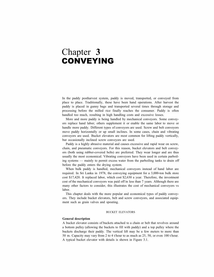
A bucket elevator consists of buckets attached to a chain or belt that revolves around
a bottom pulley (allowing the buckets to fill with paddy) and a top pulley where the
buckets discharge their paddy. The vertical lift may be a few meters to more than
50 m. Capacity may vary from 2 to 4 t/hour to as much as 25, 50, or even 100 t/hour.
A typical bucket elevator with details is shown in Figure 3.1.
Chapter 3CONVEYING
46 POSTHARVEST INDUSTRY HANDBOOK
3.1. Typical bucket eleva-
tor.

3.2. Elevators discharging
paddy: A, centrifugal; B,gravity; C, direct gravity.
3.3. Loading paddy into the boot of an elevator.
47 CONVEYING
TypesBucket elevators are available in several designs to handle many products. They are
classified according to the type of discharge used and are identified as centrifugal,
positive (gravity), and continuous (direct gravity). The three types are shown in
Figure 3.2. The centrifugal discharge type is most commonly used with grains. It is
designed and engineered to conform with general practice in handling grain. Head
and boot shafts are provided with roller bearings. Takeups are generally screw-type
except on tall high-capacity units where gravity-type take-ups are more common.
Buckets are usually made of steel or plastic and are bolted onto the belt. Casings or
legs are also made of steel, are welded or bolted together, and are dusttight. The
curved hood is designed for proper centrifugal discharge of the paddy grain. The
boot can be loaded from the front or back or both (Fig. 3.3). In larger, high-capacity
installations the head section is often vented and connected to an aspiration system.
Bucket types and capacities
Buckets are made of different materials and come in different shapes and sizes,
depending on requirements. Figure 3.4 shows a typical bucket used with centrifugal
discharge elevators. The buckets are uniform, smooth, and proportioned for fast
filling and quick, clean discharge. Figure 3.5 shows the correct method of bolting the
bucket to the belt.
Dimensions and capacities of different buckets are given in Table 3.1. The
carrying capacity is based on the angle of repose of paddy, which is normally 36° (see
line x - x in Fig. 3-4.) Because of the difficulty of loading all buckets to 100% of rated
capacity and the desirability of having a small reserve capacity in the elevator,
designers calculate carrying capacity on the basis of buckets being filled to 85 to 90%
of rated capacity.
Bucket spacing or the minimum vertical spacing between bolt holes of elevator
buckets is also shown in Table 3.1. Buckets may be as far apart as the required
capacity permits. lnstalling buckets closer than the minimum will probably result in
reduced carrying capacity because they will not fill properly at the recommended belt
speed.
Elevator capacities
The bucket elevator's capacity in tons of paddy per hour depends on bucket size and
spacing and on belt speed. Speed is the first critical factor to consider. The speed of
3.4. Bucket used for cen-
trifugal discharge eleva- tor. (Courtesy of Screw
Conveyor Corp.)

48 POSTHARVEST INDUSTRY HANDBOOK
3.5. Correct method of bolting the bucket to the
belt.
the belt in meters per minute depends on the head pulley speed. The recommended
head pulley speed depends on the pulley diameter. A properly designed bucket
elevator driven at the correct speed will make a clean discharge directly into the
throat of the head liner ensuring only slight paddy damage and little or no back-
legging or downlegging. If the head pulley speed is too slow, the buckets spill the
paddy into the legs. Paddy breakage occurs when the paddy is tumbled within the
pulley and re-elevated, as shown in Figure 3.6(A).
The optimum speed is shown in Figure 3.6(B). The buckets fill and carry optimally
and discharge the paddy directly into the throat — no spillage, no breakage.
If the head pulley speed is too fast, paddy is damaged by rough and fast handling
and the buckets will not fill properly. The buckets lose all their holding and discharge
control (Fig. 3.6(C)). The result is inefficient operation as well as excessive breakage
and undue head wear of the elevator top.
For optimum centrifugal discharge, the speed of the head pulley is calculated by
where R is the radius of the wheel plus one-half the projection of the bucket in
meters. Experience has shown that for paddy and most lightweight grains, a more
Table 3.1. Dimensions and capacities of elevator buckets.
Bucket size Capacity (cm 3)
(mm) when filled to
Length Projection Depth in Figure 3.4 line x-x
Normalspacingon belt (mm)
76102127152178203229254279305305
647089
102114127152152152152178
647695
114127140159159159159184
142283
566850
1416198231153398368139645380
102102127152165178203203203203229

49 CONVEYING
3.6. Elevator discharge at
different bucket speeds:
A, too slow; B, optimum,
C, too fast.
satisfactory operational speed is 80 to 85% of the theoretical speed. Table 3.2 shows
the recommended elevator speeds for different pulleys.
Thus, elevator capacity may be calculated from 1) bucket capacity and recom-
mended spacing found in Table 3.1, and 2) belt speed found in Table 3.2 as follows:
Elevator capacity (m 3/h) = (bucket capacity in m 3 /1,000,000) × (number of
buckets per meter of belt) × (belt speed in
meters/ minute) × (60 minutes/ h);
Pulleydiameter
(cm)
Table 3.2. Recommended elevator speeds for different size head pulleys.
Pulley Average circum-
Head pulley rpm bucket
ference projection Cal- Recom-
(cm) (cm) culated mended
30 94 10 66 41 129 10 60 51 160 10 54 61 192 13 49 76 239 15 44 91 286 18 40
122 383 20 36
56514642313431
Recommendedbelt
speeda
(m/min)
536513808998
119
aBelt speed (m/min) = (3.1416) × (pulley diameter in meters) × (recommended rpm).

50 POSTHARVEST INDUSTRY HANDBOOK
then using 576 kg/m3 for paddy and one metric ton as 1,000 kg:
Elevator capacity (t/h) = (elevator capacity in m3/h) × (576 kg/m3) ÷
For example, take a 0.41 m head pulley with 127 × 89 mm buckets on 127 mm
(1,000 kg/t).
spacing:
m3/h = (.00056 cm) 1000/127 (65 m/minute) (60) = 17.2 m3/h
t/h = (17.2) (576) ÷ 1000 = 10
Table 3.3 shows representative capacities for various head pulleys at various
rpm's.
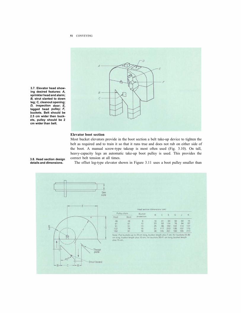
Elevator head section
Elevator heads should be of the proper shape and size with smooth contours. Figure
3.7 illustrates many of the design features that should be considered. The discharge
side of the head should be shaped so that material thrown from the buckets will not
be deflected into the downleg. The throat should be considerably below the head
shaft to catch materials that are slow leaving the buckets. Head section dimensions
for different size head pulleys are shown in Figure 3.8.
Lagging on the elevator head pulley (Fig. 3.9) is needed in pulling heavy loads.
Proper lagging increases the coefficient of friction between the pulley and belt. On
tall legs a backstop device is recommended to prevent the belt from running
backwards when elevator cups are loaded and power is cut off. A simple mechanical
rachet device serves well as a backstop.
The strut board at a 45° angle under the head pulley (Fig. 3.8) prevents the
accumulation of paddy and dust.
The throat plate should be easily replaceable so that it can be changed after it
wears out. The head shaft must be heavy enough to resist bending and to provide the
required torque carrying capacity. It must stay level and properly lined up. Antifric-
tion bearings, properly lubricated, are recommended.
Table 3.3. Average capacities of certain elevators with different speeds and bucket sizes.
Head pulley diameter
(mm)
Bucket
Size Spacing
(mm) (mm)
Capacity (t/h) with head pulley speed of
56
mm mm rpm rpm
46 31 34 51
mm
42
mm
31
rpm
30 89 × 64 102 × 70
41 102 × 70 127 × 89 152 × 102
51 152 × 102 178 × 114 203 × 127
61 203 × 127 229 × 152 254 × 152
76 254 × 152 279 × 152 305 × 178
91 305 × 178 356 × 178
122 356 × 178 356 × 203
102102
102127152152165178178203203203203229229229229254
2.65.2–––––––––––––
–––
––––
14.221.828.3
–
––––––––––
– – – – – – – – – –
6.310.012.5
– – – –
– – – – – – – –
– – – – –
– – – – – – – – – – – 31.0 – – – – 42.7 – – – – 46.6 – – –
– 51.3 – –
– – 55.6 – – – – 72.2 – – – – – 79.4 – – – – 96.2 –
– – – – 117.2 – – 137.6
–
– –
51 CONVEYING
3.7. Elevator head show-
ing desired features: A,
sprinkler head and alarm;
B, strut slanted to down
leg; C, cleanout opening;
lagged head pulley; F,D, inspection door; E,
buckets. Belt should be
2.5 cm wider then buck-
ets, pulley should be 2
cm wider than belt.
3.8. Head section design
details and dlmensions.
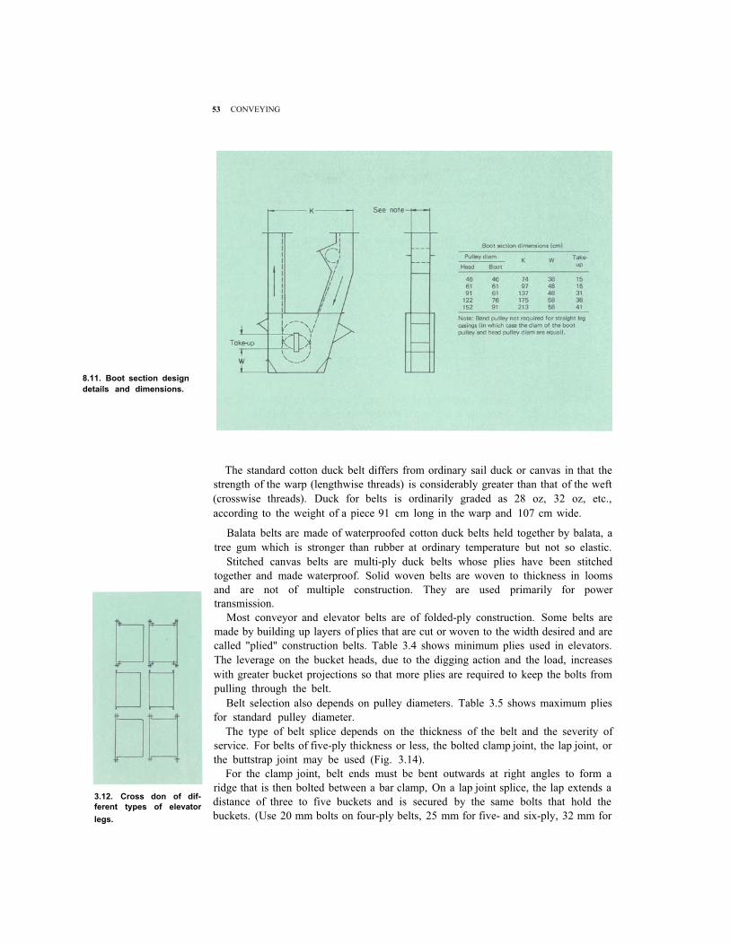
Elevator boot section
Most bucket elevators provide in the boot section a belt take-up device to tighten the
belt as required and to train it so that it runs true and does not rub on either side of
the boot. A manual screw-type takeup is most often used (Fig. 3.10). On tall,
heavy-capacity legs an automatic take-up boot pulley is used. This provides the
correct belt tension at all times.
The offset leg-type elevator shown in Figure 3.11 uses a boot pulley smaller than

52 POSTHARVEST INDUSTRY HANDBOOK
3.9. Pulley lagging.
3.10. Elevator boot sec-
tion with screw take-up
adjustment.
the head pulley, mainly to conserve space around the elevator boot. It should be no
smaller than two-thirds of the diameter of the head pulley.
Grain entry may be on either side of the boot (Fig. 3.11). However, when grain
enters on the downleg, additional power is required for the “dredging effect” of
pulling the buckets through the grain in the boot.
Cleanouts should always be included on both sides of the boot to permit fast and
easy cleaning. They are usually placed at an angle (Fig. 3.10 and 3.11) and should
slide easily.
Elevator legs
Elevator legs are constructed as all welded, bolted, or riveted units. Cross sections of
different types are shown in Figure 3.12. They are manufactured in standard lengths
of 2.4 m, but could be manufactured in any length desired. The economics of local
manufacturing cost should determine which type of leg construction to use. Some
manufacturers find it more economical to employ singlebox construction that
includes both legs, as shown in Figure 3.13.
Belts for bucket elevator
Four types of belts are used for bucket elevators and belt conveyors: 1) duck, 2)
balata, 3) stitched canvas, and 4) solid woven cotton. Any of these belts may be
treated with special preparations or covered with natural or synthetic rubber.
53 CONVEYING
8.11. Boot section design
details and dimensions.
3.12. Cross don of dif-
ferent types of elevator
legs.
The standard cotton duck belt differs from ordinary sail duck or canvas in that the
strength of the warp (lengthwise threads) is considerably greater than that of the weft
(crosswise threads). Duck for belts is ordinarily graded as 28 oz, 32 oz, etc.,
according to the weight of a piece 91 cm long in the warp and 107 cm wide.
Balata belts are made of waterproofed cotton duck belts held together by balata, a
tree gum which is stronger than rubber at ordinary temperature but not so elastic.
Stitched canvas belts are multi-ply duck belts whose plies have been stitched
together and made waterproof. Solid woven belts are woven to thickness in looms
and are not of multiple construction. They are used primarily for power
transmission.
Most conveyor and elevator belts are of folded-ply construction. Some belts are
made by building up layers of plies that are cut or woven to the width desired and are
called "plied" construction belts. Table 3.4 shows minimum plies used in elevators.
The leverage on the bucket heads, due to the digging action and the load, increases
with greater bucket projections so that more plies are required to keep the bolts from
pulling through the belt.
Belt selection also depends on pulley diameters. Table 3.5 shows maximum plies
for standard pulley diameter.
The type of belt splice depends on the thickness of the belt and the severity of
service. For belts of five-ply thickness or less, the bolted clamp joint, the lap joint, or
the buttstrap joint may be used (Fig. 3.14).
For the clamp joint, belt ends must be bent outwards at right angles to form a
ridge that is then bolted between a bar clamp, On a lap joint splice, the lap extends a
distance of three to five buckets and is secured by the same bolts that hold the
buckets. (Use 20 mm bolts on four-ply belts, 25 mm for five- and six-ply, 32 mm for

3.13. Singlebox type ele- vator leg.
3.14. Splicing elevator
belts.
54 POSTHARVEST INDUSTRY HANDBOOK
Table 3.4. Minimum plies for bucket projections
Grain Minimum plies when bucket projection is Belt
elevator 8 cm 10 cm 13 cm 15 cm 18 cm 20 cm fabric
5
5
28 oz or 32 oz
32 oz Low-speed 4 4 5 6 6
High-speed – – – 6 6
Table 3.5. Maximum belt plies vs diameter pulleys.
Head pulley Maximum Minimum foot
diam (cm) plies pulley diam (cm)
5161717691
56789
107 10 122 12
38465356667691
seven- and eight-ply.) This splice is not suitable for belts more than seven plies thick
because it is too stiff to pass tightly over the pulleys.
The butt-strap joint may be used on belts of eight or more plies. Place one bolt for
each 25 mm of belt width, 10 mm bolts for belts less than 10 plies, and 15 mm bolts
for those more than 10 plies.
Belt widths should be the bucket width, plus 25 mm. The pulley width should be
the belt width, plus 25 mm or more.
Accessories
For servicing the elevator head section, particularly the drive mechanism, a platform
for working is needed. Access to this platform is usually by ladder equipped with a
safety cage. A typical elevator with platform is shown in Figure 3.15. In some
installations, joint or common ladders are used for two or more elevators or other
machines.

55 CONVEYING
3.15. Elevator with plat-
form, ladder, and safety
cage. (Courtesy of Car-
dinal Division, LML
Corp.)
Power requirements
The theoretical horsepower (hp) requirements for bucket elevators may be obtained
from the equation:
where Q = capacity in kilograms per minute, H = lift in meters, and F = 1.5 for
elevators loaded on the down side of the boot, 1.2 for elevators loaded on the up side
of the boot. Actual horsepower requirements are 10 to 15% higher than this
theoretical value because of friction, power transmission, and drive losses. For
example, horsepower requirements for a bucket elevator with 1,600 bu/h of paddy
and a lift of 10.7 m loaded on the up side would be: (1,600 bu/h = 545 kg/minute)
Therefore the next larger standard size electric motor should be selected.

56 POSTHARVEST INDUSTRY HANDBOOK
SCREW CONVEYORS
General infomation
Figure 3.16 shows a typical screw conveyor. It consists of a conveyor screw in a
trough supported by end and hanger bearings. The screw rotation pushes the grain
along the trough. The pitch (distance from the center of one thread to the center of
the next thread) of a standard conveyor screw is equal to its diameter. A 15-cm
diameter conveyor screw has a pitch of 15 cm. For each revolution of a standard
screw conveyor the paddy is advanced a distance equal to the pitch. The screw
conveyor is used to move paddy horizontally. It can also be used at any angle up to
90° from horizontal although there will be a corresponding reduction in capacity.
The helicoid screw (Fig. 3.17A) is a continuous one-piece helix shaped from a flat
strip of steel and attached to a pipe or shaft. Its thickness decreases from the inner
edge to the outer edge because of the strength necessary to form the helix (Fig.
3.17B). Smoothness of the helix is most important. Capacities and power require-
3.16. Typical screw con-
veyor.
3.17. Hellcoid conveyor
screw section.

57 CONVEYING
ments vary with segmented or welded sections.
Paddy is much more abrasive than most other grains and causes excessive wear on
the flights as well as the trough. To reduce wear, flights (helicoid section minus the shaft) may be fabricated from various materials such as stainless steel, monel, or
copper alloys. But because these materials are generally too expensive, a high-
carbon steel or other less expensive abrasive-resistant alloy is used.
A number of other conveyor flights are designed for special purposes. The ribbon
screw conveyors convey sticky materials. Another special type is a short-pitch
conveyor — pitch may be one-half of screw diameter or less — generally used in
feeders (Fig. 3.18). The short-pitch conveyor is used under a dump pit where full
loading of the screw is expected.
Screw conveyors may be designed for clockwise or counterclockwise rotation
without change in capacity. The screw conveyor carries the material as seen in Figure
3.19, on opposite sides (right-hand or left-hand). This characteristic may be consid-
ered in certain installations, such as feeding an elevator or machine.
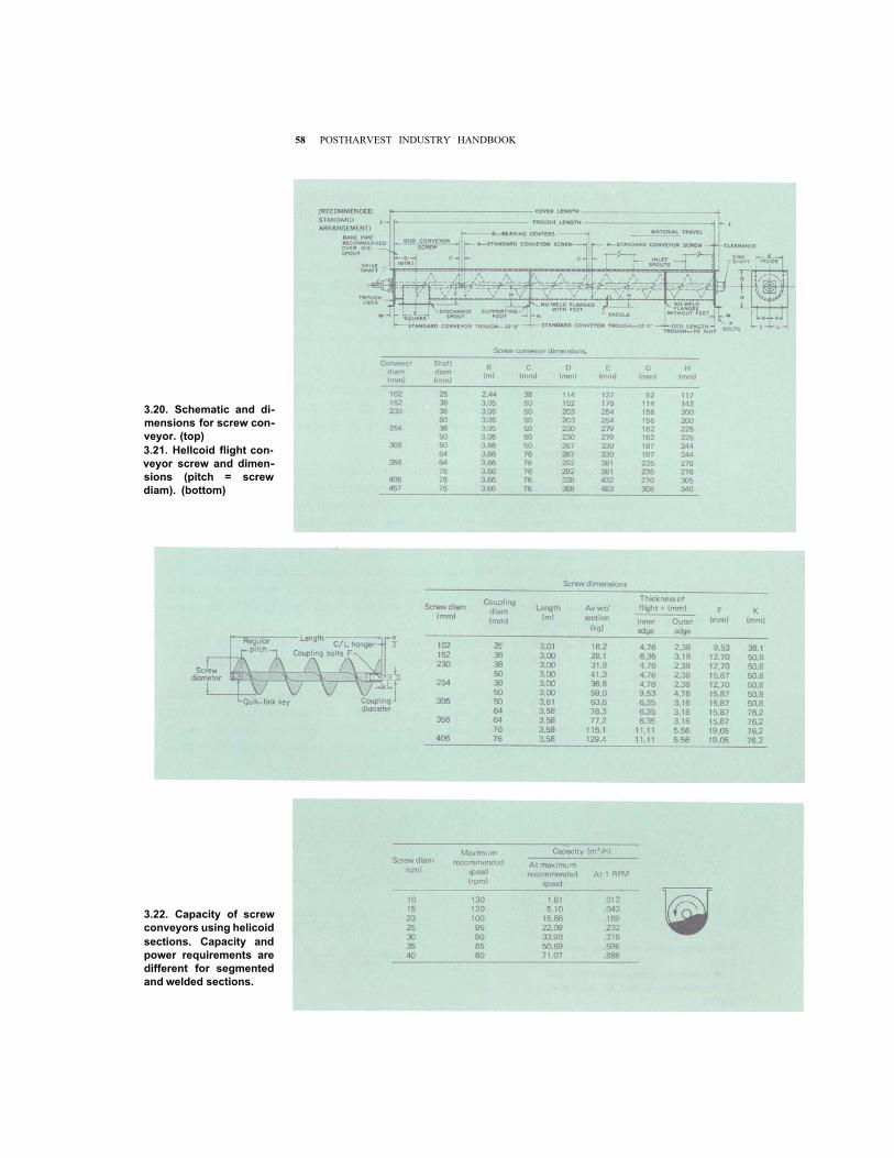
Sizes and capacities
Screw conveyor components, in addition to the screw, include end bearings, hanger
bearings, inlet openings, and discharge openings (see Fig. 3.20 for details and general
dimensions). The dimensions of the helicoid screw are given in Figure 3.21.
Paddy assumes a cross section loading of 30% during operation of a screw
conveyor as shown in Figure 3.22. Based on this loading factor, screw diameter, and
rpm, the capacity for standard size screw conveyors is shown in Figure 3.22. For
screw conveyors of standard construction, the capacity chart should always be
followed for recommended maximum speeds. Speeds selected below the maximum
recommended are conservative. Speeds above that should be referred to the manu-
facturer before they are used.
From Figure 3.22 for example, a 15-cm conveyor at maximum speed of 120 rpm
has a capacity of 5.10 m 3/hour. With paddy of 576 kg/m 3, this is 2,937 kg or about 3.0 t/ hour.
(This is 39% of the theoretical calculated capacity based on the formula
Q= (D2 – d 2)/ 36.6 × P × rpm, where Q is in ft 3/ hour, D = screw diameter in inches,
d = shaft diameter in inches, and P = pitch in inches. Because of screw housing
clearance and the loading factor, the actual capacity is less than the theoretical
capacity.)
3.18. Short pitch conveyor section.
3.19. Conveyor screw sections: A and
B, right-hand; C and D, left-hand.
(top)
(right)
58 POSTHARVEST INDUSTRY HANDBOOK
3.20. Schematic and di-
mensions for screw con-
veyor. (top)
3.21. Hellcoid flight con-
veyor screw and dimen-
sions (pitch = screw
diam). (bottom)
3.22. Capacity of screw
conveyors using helicoid
sections. Capacity and
power requirements are
different for segmented
and welded sections.

59 CONVEYING
Horsepower requirements may be determined by using the following formulas.
The determination does not consider power loss in drive equipment (belts, chains, or
gear reducers), imperfect alignment, or the power required for starting under load.
Additional power is therefore required for the average installation to overcome drive
losses and imperfect alignment.
(DS + QK)
1,000,000(1) H= L
Where L = overall length in feet
D = factor depending on type
S = speed in rpm
Q = quantity of paddy in
pounds per hour
K = material factor, for
paddy = 0.4
of bearings (Table 3.6)
(2)H×P
0.85hp=
Where P = 2 when H is less than 1
P = 1.5 when H is between 1
and 2
P = 1.25 when H is between 2
and 4
P = 1.1 when H is between 4
and 5
P = 1 when H is greater than
5 and 0.85 is estimated
efficiency of the drive
A sample problem:
paddy/ hour over a distance of 24 m.
Solution:
From Figure 3.22 (20 t/ h × 1,000 kg/ t) ÷ 576 kg/ m3 = 34.72 m3/ h), a 30-cm
screw at 92 rpm would be adequate. Then, assuming self-lubricating bronze
bearings from Table 3.6, D = 96, H = (24 × 3.281) × (171 × 150 + 44,080 × 0.4) ÷
1,000,000 = 3.41 then:
Determine conveyor size, speed, and horsepower requirements to move 20 t
3.41 × 1.25
0.85hp = =5.01
Table 3.6. “D” factors in computing horsepower for screw conveyors.
Conveyor
diam
(cm)
“D” factor for type of hanger bearings
Ball or roller
Wood, babbitt, bronze or moldedfabric
Self- lubricating
bronze
Whiteiron or
manganesesteel
7.5101523
25303540
10121832385578
106
152133546696
135186
24335496
114171255336
355080
130160250350480

60 POSTHARVEST INDUSTRY HANDBOOK
The next standard size electric motor above 5 hp should be used. The following
specifications apply: Conveyor size: 30 cm
Conveyor speed: 92 rpm
Conveyor horsepower: 7.5
Screw conveyors can be operated in an inclined position with the flow of materials
upward. However, the allowable capacity rapidly decreases as the angle of inclina-
tion increases. A standard conveyor inclined 15 degrees will carry about 75% of its
rated horizontal capacity. At an incline of 25 degrees it will carry about 50% of its
rated horizontal capacity.
The additional horsepower required over the horizontal horsepower require-
ments is roughly 25% for a 15° inclined conveyor and 50% for a 25° inclined
conveyor. For a screw conveyor operated at an incline greater than 25°, a tubular
casing or a shrouded U trough should be used. It also becomes necessary at this angle
to use shorter-than-standard pitch flights.
Hangers and end bearings
The end thrust on a conveyor screw is against the direction of material flow. An end
thrust bearing assembly absorbs this force and prevents excessive wear of the
operating parts. A number of thrust arrangements are possible. One of the most
frequently used is an outside-type thrust bearing (Fig. 3.23). Preferably, the con-
veyor drive should be installed to drive through the end thrust because the shaft is
fixed in position and cannot “float” in the end bearing. However, the drive is often
installed on the feed end of the conveyor because of space or other limitations.
A standard-type hanger bearing used for screw conveyors designed for paddy is
illustrated in Figure 3.24. The 3.175 mm pipe tap provides a connection for a grease
fitting and is most often used with a pressure-type grease cup. Additional life can be
obtained by using ball bearings with dust seals in the hanger. Shields should be
placed on the upstream side of the bearing to protect it from grain pressure and wear.
Inlets and discharge openings
Generally, inlet openings may be cut into the conveyor trough cover wherever
needed. Figure 3.20 shows inlet spouts at two locations. Inlet openings should be
kept at a sufficient distance from hanger bearings to prevent clogging or choking at
3.23. Outside type thrust bearing for heavy duty service.

61 CONVEYING
3.24. Standard hanger
bearing.
3.25. Screw conveyor dis- charge openings and
spouts.
that point. For general use, the inlet opening is square and of the same dimensions as
the inside width of the trough. The opening may be flared or an inlet spout may be
designed to meet specific needs. Special side opening inlets can also be designed to
control the depth of material fed to the trough at that point.
Discharge spouts may be flared or made longer to meet special machinery needs.
A standard opening is square and equal to the inside width of the trough. Several
types of discharge openings and spouts are illustrated in Figure 3.25.
Troughs and covers
A variety of screw conveyor troughs exist. Two types common to paddy require-
ments are shown in Figure 3.26: the flanged type with flanged cover installed (A) and
the angle flanged type without cover (B). Most troughs for handling paddy are made
of high carbon steel or abrasive-resistaat alloys to withstand the severe wear.
Other types of trough covers are illustrated in Figure 3.27. The flat cover is used
indoors where waterproofing is not necessary. For most outdoor conveyors where

62 POSTHARVEST INDUSTRY HANDBOOK
3.26. Screw conveyor
troughs. (top) 3.27. Trough covers and
clamps.
waterproofing is essential, the flanged-hip roof cover is used. Screw cover clamps are
most often used with both types of covers.
Drive arrangements
Because most screw conveyors are operated at relatively low speeds and electric
motors operate at relatively high speeds, a speed reducer is essential. Drives can be
direct coupled, or belt or chain connected as shown in Figure 3.28.

63 CONVEYING
3.28. Drive arrangements
for screw conveyors: A,
speed reducer mounted
on conveyor shaft, motor
mounted with V belt con-
nection to slde or top; B,
self-contained unit with
standard speed reducer
mounted on the shaft,
motor attached and driven
by V belt; C, gear motor
with built-in speed redu-
cer, chain drlve to screw
shaft,
3.29. Auger systems: A,portable; B, installed-in-
bin.
Portable and bin augers
The previous section on screw conveyors provides design data on heavy-duty,
continuous-operation screw conveyors, the type which would be used in a paddy
storage-processing plant.
In many small storage installations, however, it may be necessary to load and
unload bins only a few times per year. This type of operation does not require the
type of screw conveyors just described. A number of manufacturers produce special
screw conveyors for occasional use. They are generally known as augers. Figure 3.29
shows portable augers A used on an incline to move paddy from a tractor-trailer into
a dryer and from the dryer into a storage bin, and a horizontal unloading auger B
under the floor of a storage bin and a vertical auger to move paddy from the storage
bin to a truck or into a rice mill. These light-duty augers (fewer operating hours per
year) are housed in lightweight closed tubes instead of an open U trough.
Most often they are operated at higher rpm’s than those recommended for
heavy-duty screw conveyors shown in Figure 3.22. Thus they achieve higher capaci-
ties than small-diameter screw conveyors. Generally these augers are less expensive
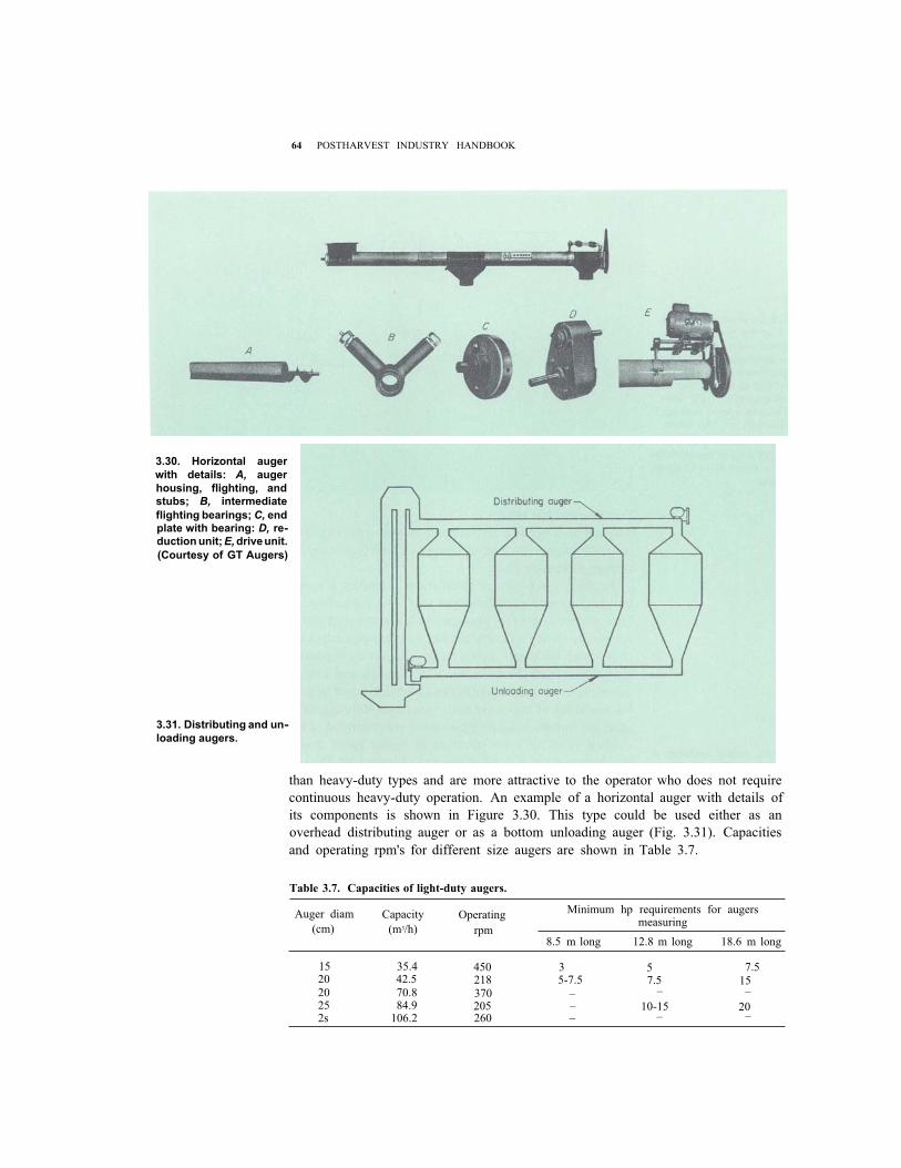
64 POSTHARVEST INDUSTRY HANDBOOK
3.30. Horizontal auger
with details: A, auger
housing, flighting, and
stubs; B, intermediate
flighting bearings; C, end
plate with bearing: D, re-
duction unit; E,drive unit.
(Courtesy of GT Augers)
3.31. Distributing and un-
loading augers.
than heavy-duty types and are more attractive to the operator who does not require
continuous heavy-duty operation. An example of a horizontal auger with details of
its components is shown in Figure 3.30. This type could be used either as an
overhead distributing auger or as a bottom unloading auger (Fig. 3.31). Capacities
and operating rpm's for different size augers are shown in Table 3.7.
Table 3.7. Capacities of light-duty augers.
Auger diam
(cm)
Capacity
(m3/h)
Operating
rpm
Minimum hp requirements for augers measuring
8.5 m long 12.8 m long 18.6 m long
15 35.4 450 3 520 42.5 218 5-7.5 7.520 70.8 370 – –
25 84.9 205 – 10-152s 106.2 260 – –
15
20
7.5
–
–

65 CONVEYING
When the auger is operated in a vertical position, the capacity is greatly reduced.
For example, when the 15-cm auger in Table 3.7 is operated vertically it has only 20
m3 /hour capacity at 620 rpm; the 20-cm auger, only 35.4 m3 / hour capacity at 620
rpm. Capacities vary with manufacturers.
Portable augers are designed with the same type trough and screw flight construc-
tion as the horizontal augers, but they need extra outside reinforcement because of
their long lengths (Fig. 3.32). They are adjustable in height or angle to meet the needs
of different size bins or dryers. They may be powered by electric motors or gasoline
engines, or be driven by a tractor power takeoff. They are available in 15-cm, 20-cm,
or 25-cm diameters. Their capacities vary considerably; for example, a 20-cm auger
operating at an angle of 20° may have a capacity of 70 m3 / hour. But the same size
auger operating at 45° may have a reduced capacity of only 50 m3 / hour.
Minimum electrical horsepower requirements could increase by 1/3 with wet
paddy if the same capacity in cubic meters per hour is maintained.
Other portable augers are available in smaller diameters, in varying lengths, and
for different operational needs.
BELT CONVEYORS
A belt conveyor (Fig. 3.33) is an endless belt operating between two pulleys with its
load supported on idlers. It may be flat for moving bags of paddy, or V-shaped for
3.32. Portable auger.
(Courtesy of GT Augers)
3.33. Typical belt con-
veyor.
66 POSTHARVEST INDUSTRY HANDBOOK
moving bulk paddy. The belt conveyor consists of a belt, drive and end pulleys,
idlers, a drive and tension mechanism, and loading and discharge devices. Its
carrying capacity depends on the belt width, angle of trough, and belt speed.
Belt conveyors have a high mechanical efficiency because the load is carried on
antifriction bearings. Damage to paddy is virtually nil because there is no relative
motion between the paddy grains and the belt. Carrying capacity is high because
relatively high speeds are possible. Paddy can be conveyed a long distance. A
properly designed and maintained belt system has long service life and low operating
cost. The initial cost is high for short distance belts and relatively low for long
distance belts compared to other types of horizontal conveyors. For these reasons,
belt conveyors are widely used to move paddy in many installations. They range
from 30-100 cm in width, and may be up to several hundred meters in length.
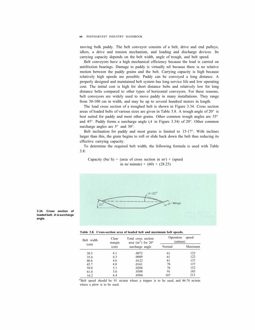
The load cross section of a troughed belt is shown in Figure 3.34. Cross section
areas of loaded belts of various sizes are given in Table 3.8. A trough angle of 20° is
best suited for paddy and most other grains. Other common trough angles are 35°
and 45°. Paddy forms a surcharge angle ( A in Figure 3.34) of 20°. Other common
surcharge angles are 5° and 30°.
Belt inclination for paddy and most grains is limited to 15-17°. With inclines
larger than this, the grain begins to roll or slide back down the belt thus reducing its
effective carrying capacity.
To determine the required belt width, the following formula is used with Table
3.8:
Capacity (bu/ h) = (area of cross section in m2) × (speed
in m/ minute) × (60) × (28.25)
3.34. Cross section of
loaded belt: A is surcharge
angle.
Table 3.8. Cross-section area of loaded belt and maximum belt speeds.
Belt width
(cm)
Clear Total cross section Operation speeda
margin area (m 2) for 20° (mlmin)
(cm) surcharge angle Normal Maximum
30.535.640.645.750.861.016.2
4.14.34.64.85.15.66.4
.0072
.0089
.0122
.0161
.0204
.0308
.0504
616161767691
107
122122137137152183213
aBelt speed should be 91 m/min where a tripper is to be used, and 46-76 m/min
where a plow is to be used.
67 CONVEYING
Example: Determine belt width and speed to convey 1,200 bu of paddy/ hour. Using
the cross sections from Table 3.8, a 35.6 cm belt traveling at 81 m/ minute would give:
.0089 × 81 × 60 × 28.25 = 1,221 bu/ hour
and a 30.5 cm belt traveling at 99 m/minute would give:
.0072 × 99 × 60 × 28.25 = 1,208 bu/ hour.
In this example the 35.6-cm-wide belt at 81 m/ minute is adequate, unless a tripper is
to be used (minimum of 91 m/minute for tripper use). Then the 30.5-cm belt at 99
m/minute should be used.
The top idler spacing should be 1.5 m for belts up to 0.5 m wide and 1.4 m for belts
0.6-0.9 m wide. The return idler spacing for belts up to 0.9 m wide should not exceed
3 m. After belt speed in meters per minute has been determined, then rpm of the head
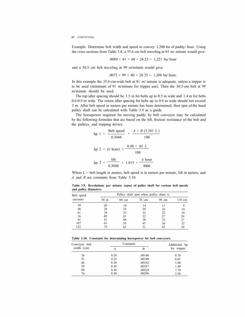
pulley shaft can be calculated with Table 3.9 as a guide.
The horsepower required for moving paddy by belt conveyor may be calculated
by the following formulas that are based on the lift, friction resistance of the belt and
the pulleys, and tripping device.
Belt speed A + B (3.281 L )hp 1 =
0.3048×
100
hp 2 = (t/ hour) × 0.48 + .01 L
100
lift t/ hour hp 3 = × 1.015 ×
0.3048 l000
Where L = belt length in meters, belt speed is in meters per minute, lift in meters, and
A and B are constants from Table 3.10.
Table 3.9. Revolutions per minute (rpm) of pulley shaft for various belt speeds
and pulley diameters.
Belt speed
(m/min)
Pulley shaft rpm when pulley diam is
50 m 60 cm 76 cm 90 cm 110 cm
3046611691
107122
20283848556575
16243241485565
1420
2532384551
11162227323843
9141824273236
Table 3.10. Constants for determining horsepower for belt conveyors.
Conveyor belt width (cm)
Constants
A B
Additional hp for tripper
3641
46506076
0.20 .00140 0.25 .00140 0.30 .00162 0.30 .00187 0.36 .00224 0.48 .00298
0.700.851.001.401.702.50

68 POSTHARVEST INDUSTRY HANDBOOK
3.35. Cross section of belt
conveyor: A, drive pulley;
B, idler; C, tripper, D, feed
hopper; E, adjustable belt-
tensioning pulley. (below) 3.36. Belt loading arrange-
ment showing metal or wood frame with rubber
skirt and extra set of
idlers. (bottom)
The total horsepower required is the sum of the powers calculated from the three
equations, plus that required for the tripper from Table 3.10.
For example: A belt carrying 18 t/hour, 41 cm wide, traveling at 110 m/minute for a
distance of 90 m, with a 3-m lift:
110 0.25 + (.0014) (3.281) (90) hp 1 =
0.3048×
100= 2.39
.048 + (.10) (90)
100hp 2 = 18 ×
hp 3 = 3
0.3048
18× 1.015 ×
1000
= 0.25
= 0.18
Plus for the tripper (from Table 3.10) = 0.70
Total hp = 3.52
A cross section of a belt conveyor with its major parts is shown in Figure 3.35.
Note that the feed hopper is installed near the upper end of the belt. It has guides on
the side to prevent the paddy from splashing off as it feeds onto the belt. These guides
may be metal or wood, 60-90 cm long, installed slightly above the belt surface to
prevent wear on the belt. Details are shown in Figure 3.36.
In Figure 3.35, the belt moves along the top idlers, which are spaced close together
to carry the load. The tail pulley is adjustable to maintain the correct belt tension.
Paddy is discharged by a belt tripper, which is movable along the length of the belt
and incorporates a two-way discharge valve so that the paddy can be discharged on
69 CONVEYING
either side of the belt.
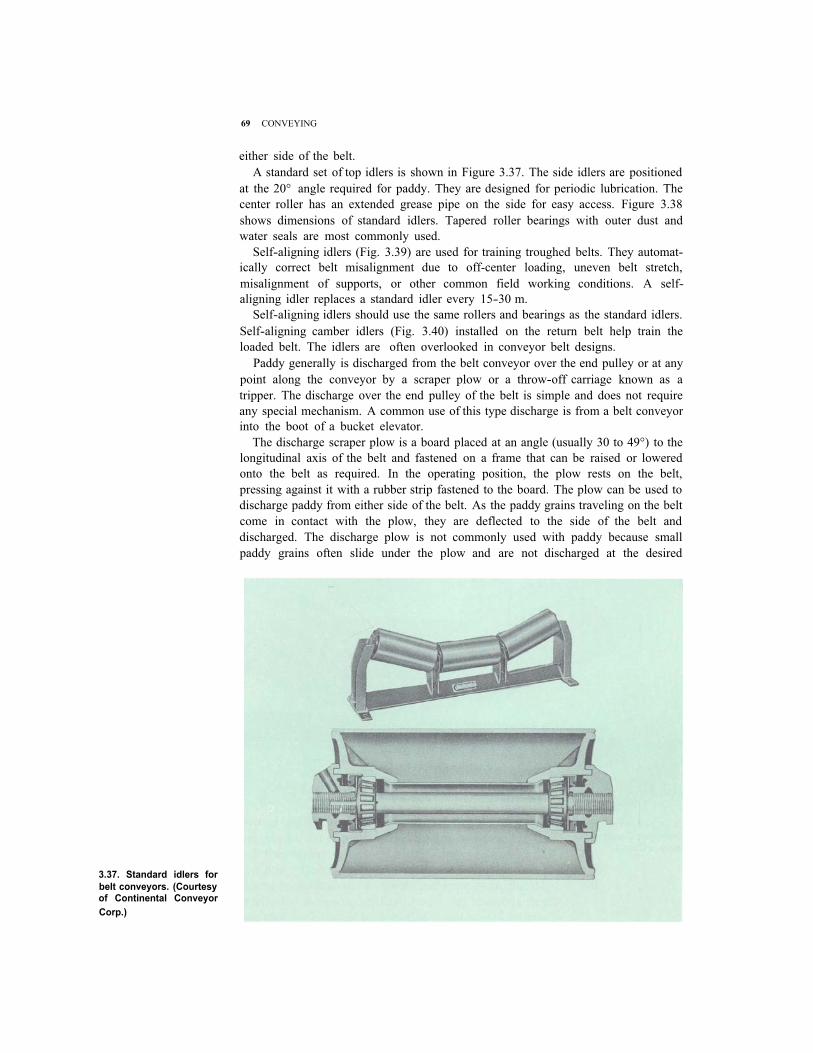
A standard set of top idlers is shown in Figure 3.37. The side idlers are positioned
at the 20° angle required for paddy. They are designed for periodic lubrication. The
center roller has an extended grease pipe on the side for easy access. Figure 3.38
shows dimensions of standard idlers. Tapered roller bearings with outer dust and
water seals are most commonly used.
Self-aligning idlers (Fig. 3.39) are used for training troughed belts. They automat-
ically correct belt misalignment due to off-center loading, uneven belt stretch,
misalignment of supports, or other common field working conditions. A self-
aligning idler replaces a standard idler every 15-30 m.
Self-aligning idlers should use the same rollers and bearings as the standard idlers.
Self-aligning camber idlers (Fig. 3.40) installed on the return belt help train the
loaded belt. The idlers are often overlooked in conveyor belt designs.
Paddy generally is discharged from the belt conveyor over the end pulley or at any
point along the conveyor by a scraper plow or a throw-off carriage known as a
tripper. The discharge over the end pulley of the belt is simple and does not require
any special mechanism. A common use of this type discharge is from a belt conveyor
into the boot of a bucket elevator.
The discharge scraper plow is a board placed at an angle (usually 30 to 49°) to the
longitudinal axis of the belt and fastened on a frame that can be raised or lowered
onto the belt as required. In the operating position, the plow rests on the belt,
pressing against it with a rubber strip fastened to the board. The plow can be used to
discharge paddy from either side of the belt. As the paddy grains traveling on the belt
come in contact with the plow, they are deflected to the side of the belt and
discharged. The discharge plow is not commonly used with paddy because small
paddy grains often slide under the plow and are not discharged at the desired
3.37. Standard idlers for
belt conveyors. (Courtesy of Continental Conveyor
Corp.)

3.38. Dimensions of stand-
ard idlers using 12.7 em
center rollers.
3.39. Self-aligning idlers.
(Courtesy of Continental
Conveyor Corp.)
location. Also, some grains are crushed or cracked between the plow and the belt
surface. If the plow is adjusted too close to the belt, excess belt wear results.
Trippers are available as hand-propelled, self-propelled, or automatic. The choice
depends on the particular installation, its capacity, and system operation. A simple
light-duty hand-propelled tripper and its dimensions are shown in Figure 3.41. Note
the direction of belt travel. As the belt passes over the top pulley, the paddy is
discharged immediately and spouted to the left or right as desired. The hand crank
70 POSTHARVEST INDUSTRY HANDBOOK

3.40. Self-aligning cam-
ber return idlers. (Cour-
tesy of Continental Con-
veyor Corp.)
3.41. Schematic and di-
mensions of light-duty,
hand-propelled tripper
for various belt widths.
(Courtesy of Continental
Conveyor Corp.)
71 CONVEYING
with chain drive on the side permits the operator to move the tripper in either
direction along the belt. A tripper normally is installed on two I-beams running the
length of the belt conveyor and becomes part of the conveyor's frame.
Note the two-way flip-flop valve in Figure 3.41, which permits the grain to be
discharged on either side of the belt as desired. This is a simple arrangement used in

3.42. Vertical automatic
gravity belt tensioner.
(below)
3.43. Rubber lagged pul-
ley. (right)
72 POSTHARVEST INDUSTRY HANDBOOK
most installations.
The tripper also has a locking device that keeps it from moving when the belt is
carrying paddy. The device is usually a vertical pin, dropped through a fixed opening
to keep the tripper in the locked position during operation.
For heavy-duty installations and when the tripper is to be moved often, a
self-propelled or automatic tripper is often preferred. The self-popelled tripper
involves an extra set of pulleys which are used to drive the tripper.
Automatic gravity take-ups are recommended for the longer belt conveyors to
properly maintain the required driving tension at the head pulley. Where the proper
tension has been obtained by this type of take-up, it will be maintained for the life of
the belt, independent of operating conditions. Figure 3.42 shows a vertical unit. The
take-up frame slides up and down on pipe guides. The minimum take-up pulley
diameter in inches equals four times the number of belt plies. Minimum bend pulley
diameter in inches equals three times the number of belt plies.
Figure 3.35 shows a horizontal, adjustable tail pulley for belt tension adjustment.
This may be a simple screw adjustment for short, low-capacity conveyors (the same
type used for belt tension in bucket elevators in Fig. 3.11). Or it may be similar to that
in Figure 3.42, where the weight is suspended over a set of pulleys for gravity control.
Pulleys with rubber lagging are recommended when additional traction between
belt and pulley is required and when pulleys are operated under wet conditions.
Lagging may be vulcanized to the pulley (Fig. 3.43) or bolted on (Fig. 3.9). Wing-
type pulleys are usually heavy-duty, all-welded construction. The sloping wing plates
automatically shed the material to each side of the pulley to prevent buildup on the
pulley face, which can cause considerable damage to the belt. Welded steel wing
pulleys (Fig. 3.44) are recommended for tail shafts of belt conveyors and boot shafts
of bucket elevators. For pulleys with diameter of 30-34 cm, 9 wings are provided;
40-cm pulleys have 10 wings; 44-60 cm have 12 wings; and 66-91 cm have 16 wings.
Belt conveyor drives can be of several designs; the choice depends on the economy
of available materials. The most common are the gear motor type directly connected
or connected with a chain drive. V-belts are used from motor to a countershaft or
connected with a chain drive. V-belts are also used from motor to a directly
connected speed reducer (Fig. 3.45).

73 CONVEYING
3.44. Wing-type pulley.
3.45. Belt conveyor drives
A, simple chain drive from
power source; B, direct
gear motor; C, gear motor
with chain reduction to
shaft; D, V-belt drive to
countershaft with gear to
head shaft; E, V-belt to
speed reducer (direct
connected); F, motor to
head shaft.
speed reducer coupled to
OTHER PADDY CONVEYORS
Several other type conveyors are occasionally used to move paddy. They include
shaker (vibrating), chain (drag), and pneumatic conveyors. The major disadvantage
of the shaker conveyor is its limited capacity. The major disadvantage of chain and
pneumatic conveyors is their short life due to the extreme abrasiveness of paddy

74 POSTHARVEST INDUSTRY HANDBOOK
compared to other grains. Because these conveyors are seldom used for moving
paddy, their discussion is limited.
Shaker conveyor
Shaker (also called vibrating, oscillating, or grasshopper) conveyors move paddy in
a uniform, continuous flow by the upward and forward oscillating motion of a
continuous trough that is mounted on sturdy inclined reactor legs (Fig. 3.46). The
conveyor consists of a steel or wood trough mounted on flat spring, resilient support
legs with a positive action drive. The drive consists of a motor turning a shaft on
which an eccentric provides the oscillating action to the trough.
The shaker conveyor is designed for horizontal conveying. It is particularly suited
for moving wet paddy from the parboiling tanks to the dryer. In this case, the bottom
of the trough is perforated to permit excess water from the parboiled paddy to drain
before reaching the elevator leg.
The carrying capacity of the shaker is small. A trough 30 cm wide by 10 cm deep
would be limited to about 5 t/ hour. A 46- × 10-cm trough would have a capacity of
about 7.5 t/ hour. Horsepower requirements are low. A 5-t/ hour shaker conveyor
would be limited to a maximum length of 21 m and would require 1 hp.
Chain conveyor
Chain conveyors are inexpensive, slow, noisy, and mechanically inefficient. To move
paddy, scrapers or drags used with the chain operating in a closed container or
trough incur excessive wear due to the abrasive paddy. Figure 3.47 shows the cross
section of the conveyor trough and the normal movement of paddy as it is dragged
by the conveyor chain. Horsepower requirements for chain conveyors are more than
for belt or shaker conveyors of the same capacity. Because of the highly abrasive
nature of paddy, the expected life of the chain conveyor is considerably less than that
of the belt conveyor.
3.46. Shaker or vibrating-
type conveyor showing spring mounting and
power drive.

75 CONVEYING
3.47. Cross section of
chain-drag conveyor.
Pneumatic conveyor
Pneumatic conveyors move material in a closed-duct system by a high-velocity air
stream. The system uses a material feeder or collector, an air blower, ducts, and a
cyclone for collection or discharge. Figure 3.48 illustrates a common use of the
pneumatic system — unloading ships or railcars and conveying the grain into a
storage or another handling system.
The power requirements for a pneumatic conveyor are high. A larger problem is
the excessive wear on the equipment caused by the highly abrasive paddy. Therefore,
the pneumatic system is seldom used for moving paddy.
The pneumatic conveying system is most useful in handling less dense paddy husk
and other by-products such as bran and fine brokens. It is hard to beat for handling
husk and bran. Wear is minimized by the proper duct design, velocity considerations
(not too fast, not too slow), and matching the system to the requirements.
3.48. Typical pneumatic
conveying system.

3.49. Portable conveyor. (Courtesy of Cardinal
Division, LML Corp.)
76 POSTHARVEST INDUSTRY HANDBOOK
Portable conveyor
Another type of portable loader or inclined elevator is shown in Figure 3.49. It is
chain driven with paddles attached to the chain, which operates in a metal trough. It
is used to move bulk paddy and gunny bags of paddy to higher sites. It may be 9-21 m
long and is most useful as a supplement to labor in stacking bags of paddy in large
storage facilities.
GRAIN VALVES AND SPOUTING
In most paddy-handling installations, grain valves and grain spouting are used with
bucket elevators and screw conveyors. Paddy moves by gravity through these grain
valves and spouting. Because the angle of repose for paddy is 36-37° all spouting is
installed at a minimum angle of 45°. Discharge valves are designed for this minimum
angle and as long as that angle is maintained, paddy should flow freely.

77 CONVEYING
Most spouting is straight steel pipe with flanged or unflanged ends, depending on
installation requirements. Spouting 15 cm in diameter is usually available in 14 or 12
ga; 20 cm is available in 10, 12, or 14 ga. Standard 22.5°, 45°, and 60° elbows are
available. Adjustable elbows that make installation much easier are also available.
For capacities of 1,500 bu/hour (30 t/hour) or less, 15-cm spouting and valves are
adequate. For capacities from 1,500 to 3,000 bu/hour (60 t), 20-cm spouting is used.
From 3,000 bu to 4,500 bu/hour (90 t), 25-cm spouting is used.
The impact of falling paddy is extremely abrasive and rapidly wears out spouting
and elbows. A grain trap such as that shown in Figure 3.50 is used where falling
paddy would cause excessive wear on the elbow. The abrasive action of the paddy is
absorbed by the trapped grain and saves wear on the elbow.
3.50. Grain trap used to
reduce wear on elbows.
3.51. Two-way valve with bucket-type gate.

78 POSTHARVEST INDUSTRY HANDBOOK
Two- and three-way grain valves are the most common. They operate on either
the bucket-type gate as shown in Figure 3.51 or the flop gate as shown in Figure 3.52.
Spring tension enables the valve to open in either direction, The internal gate is
fabricated of abrasive-resistant steel. The valve may be operated by chain or cable.
Normal dimensions for these valves are given below:
Valve dimensions (cm)
A B C D E
15-cm spouting
20-cm spouting
21.6
26.7
25-cm spouting 31.8
15.2
20.3
25.4
38.1
45.7
54.6
31.7
36.8
40.6
50.8
57.2
61.0
Two- and three-way valves are also available with round inlets and outlets. They
come in different styles (Fig. 3.53) depending on the installation requirements. The
same general dimensions given for gates with square inlets and outlets apply.
Many installations require multiple distribution valves. An elevator in a drying
system may be connected to six tempering bins and one dryer. For more than three
outlets, distributors are used. Typical distributors are shown in Figure 3.54. Note
that the inside of each turns to make connections with the desired opening or spout.
Distributors can be made with many spouts and usually contain one spout as an
overflow. Dimensions of a typical distributor are shown in Figure 3.55.
3.52 Three-way valve with
flop gate. (top) 3.53. Two-way and three-
way valve arrangements.
(right)

79 CONVEYING
3.54. Five-way distributor.
(top)3.55. Schematic and di-
mensions for two sizes of
distributors. (upper right)
3.56. Schematic of eleva-
tor. A, total height; B,
head clearance; C, nor-
mally quoted effective ele-
vating height; D, headloss due to distributor or
valves;E, effective elevat-
ing height with distribu-
tor; F, hopper height up leg feed; G, hopper height
down leg feed. (lower
right)
80 POSTHARVEST INDUSTRY HANDBOOK
The distributor is controlled by either cable or steel rod from an indicator at
ground level. Note the control rod at the bottom of the distributor in Figure 3.55.
Dimensions of grain valves and distributors are important in determining the
required elevator height. Because grain spouting from an elevator to a dryer or a bin
must be kept at 45° angle, the height of the valve or distributor is added to the height
of the elevator.
Figure 3.56 shows the effective elevator height as the total height minus 1) head
clearance, 2) head loss due to the distributor, and 3) hopper height. The normal
quoted effective elevating height is the total height minus only the head clearance
and the hopper height.