low-speed wind-tunnel investigation of the stability and ...mln/ltrs-pdfs/nasa-95-tm4671.pdf ·...
TRANSCRIPT
National Aeronautics and Space AdministrationLangley Research Center • Hampton, Virginia 23681-0001
NASA Technical Memorandum 4671
Low-Speed Wind-Tunnel Investigation of theStability and Control Characteristics of a Seriesof Flying Wings With Sweep Angles of 70°Holly M. RossLangley Research Center • Hampton, Virginia
Scott P. FearsLockheed Engineering & Sciences Company • Hampton, Virginia
Thomas M. MoulLangley Research Center • Hampton, Virginia
September 1995
Printed copies available from the following:
NASA Center for AeroSpace Information National Technical Information Service (NTIS)800 Elkridge Landing Road 5285 Port Royal RoadLinthicum Heights, MD 21090-2934 Springfield, VA 22161-2171(301) 621-0390 (703) 487-4650
Available electronically at the following URL address: http://techreports.larc.nasa.gov/ltrs/ltrs.html
Summary
A wind-tunnel investigation was conducted in theLangley 12-Foot Low-Speed Tunnel to study the low-speed stability and control characteristics of a series offour flying wings over an extended range of angle ofattack (−8° to 48°). Because of the current emphasis onreducing the radar cross section (RCS) of new militaryaircraft, the planform of each wing was composed oflines swept at a relatively high angle of 70°, and all thetrailing edges and control surface hinge lines werealigned with one of the two leading edges. Three arrowplanforms with different aspect ratios and one diamondplanform were tested. The models incorporated leading-edge flaps for improved longitudinal characteristics andlateral stability and had three sets of trailing-edge flapsthat were deflected differentially for roll control, sym-metrically for pitch control, and in a split fashion for yawcontrol. Three top body widths and two sizes of twin ver-tical tails were also tested on each model. A large aero-dynamic database was compiled that could be used toevaluate some of the trade-offs involved in the design ofa configuration with a reduced RCS and good flightdynamic characteristics.
The results of the investigation indicate that thearrow wings experienced a pitch-up that became moresevere as aspect ratio was increased. This pitch-up wasreduced or delayed by deflecting the leading-edge flaps.When deflected symmetrically, the inboard and middletrailing-edge flaps produced small increments in pitchingmoment, especially in the nose-down direction. Despitethis limited control, each of the wings could be staticallytrimmed over a large angle-of-attack range, but addi-tional pitch control power would likely be needed to pro-vide these wings with sufficient control margin fordynamic situations such as maneuvering or counteringturbulence. An additional limit on the pitch control pro-vided by the flaps may be imposed by the need to budgetthe amount of flap deflection available for each type ofcontrol (pitch, roll, or yaw). For these reasons, thesewings would probably require redesigned flaps or addi-tional pitch control devices to achieve desired levels ofpitch control.
When the vertical tails were not used, each of thewings exhibited neutral or unstable directional stabilityand was laterally stable for angles of attack below maxi-mum lift. However, directional and lateral stability weresignificantly reduced near maximum lift on each of thewings. Increases in aspect ratio reduced lateral stabilitythroughout the test angle-of-attack range. Lateral anddirectional stability were reduced by adding top bodies ordeflecting the leading-edge flaps. Directional stabilitywas improved by adding twin vertical tails.
For each of the wings, differential deflections of thetrailing-edge flaps provided small levels of roll controlthat were relatively invariant with angle of attack, andsplit deflections of these flaps produced small yawingmoments on some of the configurations. On the forward-swept outboard flaps, the side force produced a yawing-moment increment that opposed the yawing moment pro-duced by the drag on the flap. In contrast, the side forcegenerated by split deflection of the rearward-swept mid-dle flaps produced yawing-moment increments in thesame direction as the drag, and the middle flaps thereforeprovided more effective yaw control than the outboardflaps. Supplemental yaw control could be obtained fromdeflections of the twin vertical tails.
Introduction
Recent advances in low-observables technology,which increase the effectiveness and survivability of mil-itary aircraft, have strongly influenced most new designs.When attempting to achieve low observability, some orall of the aircraft signatures (radar, infrared, visual, oracoustic) may be considered, depending on missionrequirements. One primary method of reducing radarobservability is to decrease the radar cross section (RCS)of the aircraft by appropriately tailoring the external con-tours of the configuration. However, when thesereduced-RCS shaping constraints are emphasized, theresulting aircraft may have an unconventional forebodyshape, wing planform, or tail geometry. Each of thesedesign features can have a large influence on the stabilityand control characteristics of the configuration; thus, apotential conflict exists between achieving a reducedRCS and achieving good flight dynamic characteristics.If the aircraft is a fighter, the goal to maneuver effec-tively during close-in engagements will require good sta-bility and control characteristics for angles of attack up toand beyond maximum lift. As a result, designers will berequired to balance the attributes of maneuverability andlow observability to create a fighter that will be success-ful in both close-in and beyond-visual-range engage-ments. For other types of aircraft, the stability andcontrol requirements may be less stringent, and thedesigns may be more strongly influenced by low-observability considerations.
This study consists of an investigation of flying wingcandidates for aircraft with reduced RCS. The wingplanforms have highly swept leading and trailing edges,with the trailing edges and control surface hinge linesaligned with one of the two leading edges. The wingswere divided into three groups corresponding to thesweep angles of the leading and trailing edges (50°, 60°,and 70°). Each group consisted of a diamond planformand three arrow planforms of different aspect ratio. As a
2
result of the high sweep angles, some of the planformswere somewhat unconventional in appearance.
This report presents the results of a static low-speedwind-tunnel investigation of the group of flying wingswith sweep angles of 70°. The results for the wings withsweep angles of 60° and 50° are reported in references 1and 2, respectively. Tests were conducted to determinethe low-speed stability and control characteristics of thebasic wing planforms over a wide range of angle ofattack and angle of sideslip. In addition, several controlconcepts, a broad matrix of control settings, differencesin top body width, and two sizes of twin vertical tailswere also tested. The data obtained on these wing plan-forms contribute to an aerodynamic database that couldbe used in defining some of the trade-offs associated withdesigning for both reduced RCS and good stability andcontrol characteristics.
Symbols
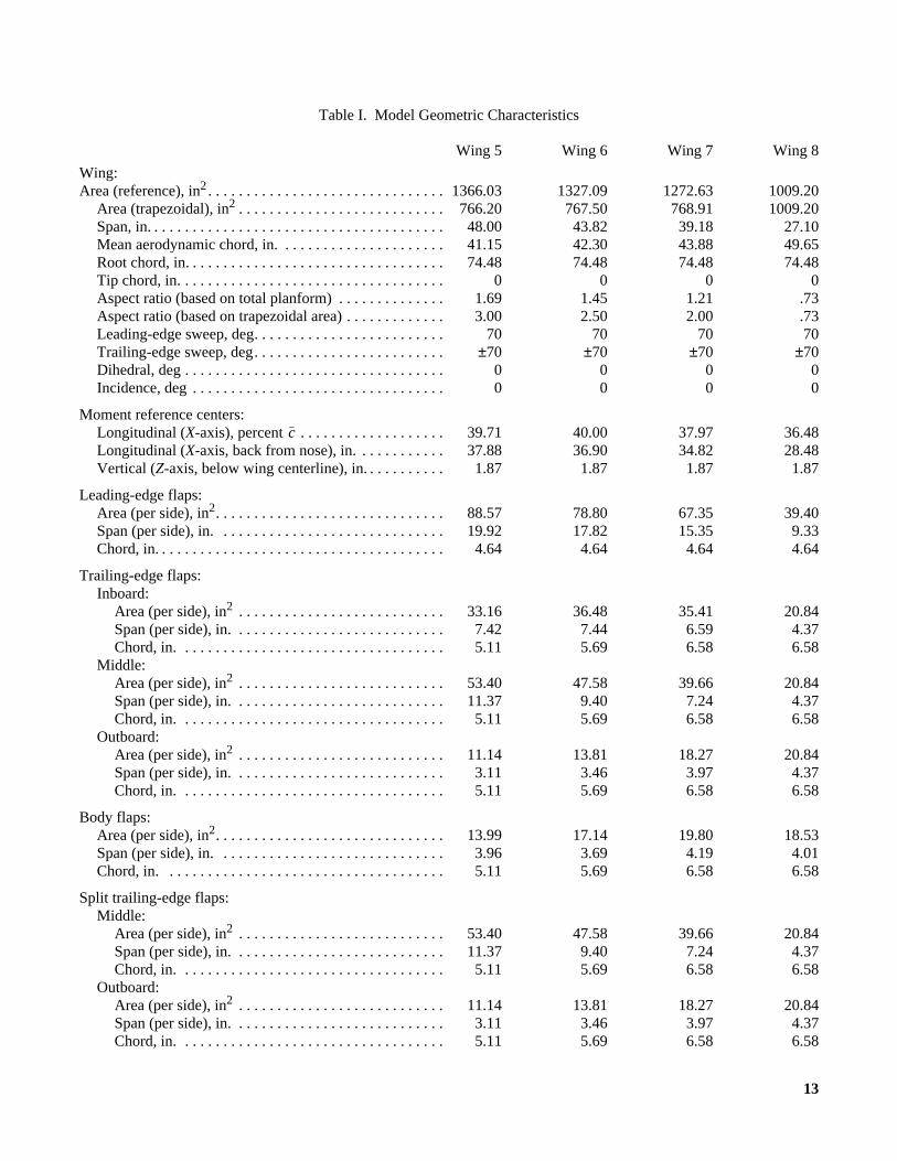
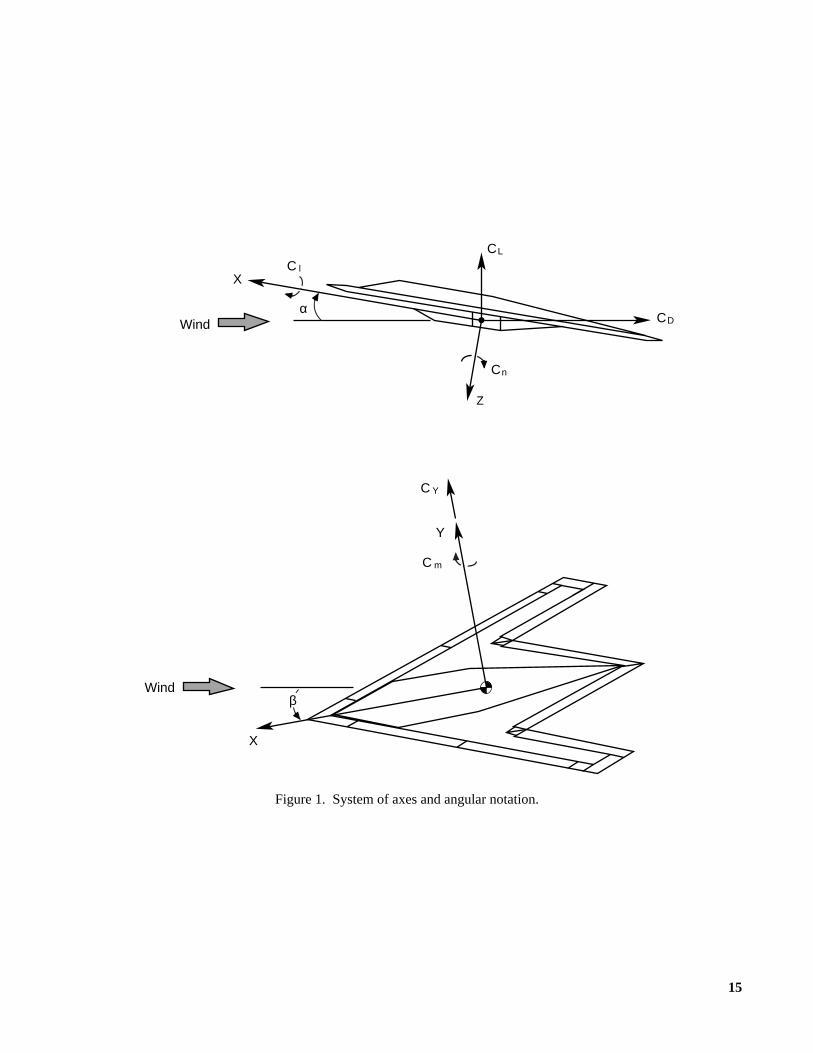
All longitudinal forces and moments are referredto the stability-axis system, and all lateral-directionalforces and moments are referred to the body-axis system(fig. 1). The longitudinal location of the moment refer-ence center (MRC) varied among the different wings.This position was chosen such that each configurationwould have neutral longitudinal stability at angles ofattack near 0° when all the controls were undeflected(table I). The MRC vertical position was fixed at 1.87 in.(2.51 percent of root chord) below the wing horizontalplane on all the configurations. The total planform area(table I) was used to nondimensionalize the force andmoment data.
b wingspan, ft
CD drag coefficient,
CL lift coefficient,
Cl rolling-moment coefficient,
Cm pitching-moment coefficient,
Cn yawing-moment coefficient,
CY side-force coefficient,
mean aerodynamic chord (based on entire plan-form), ft
free-stream dynamic pressure, lb/ft2
S reference area (based on entire planform), ft2
Drag forceqS
-------------------------
Lift forceqS
------------------------
Rolling momentqSb
---------------------------------------
Pitching momentqSc
-----------------------------------------
Yawing momentqSb
----------------------------------------
Side forceqS
------------------------
c
q
X, Y, Z longitudinal, lateral, and vertical body axis,respectively
α angle of attack, deg
β angle of sideslip, deg
∆Cl incremental rolling-moment coefficient,Cl,control deflected− Cl,control undeflected
∆Cn incremental yawing-moment coefficient,Cn,control deflected− Cn,control undeflected
∆CY incremental side-force coefficient,CY,control deflected− CY,control undeflected
δa,IB differential deflection angle of inboardtrailing-edge flaps based on equal and oppo-site deflection, positive with trailing edgedown on right wing, measured normal tohinge line, deg
δa,MID differential deflection angle of middle trailing-edge flaps based on equal and opposite deflec-tion, positive with trailing edge down on rightwing, measured normal to hinge line, deg
δa,OB differential deflection angle of outboardtrailing-edge flaps based on equal and oppo-site deflection, positive with trailing edgedown on right wing, measured normal tohinge line, deg
δbf symmetric deflection angle of body flaps, pos-itive with trailing edge down, measured nor-mal to hinge line, deg
δf,IB symmetric deflection angle of inboardtrailing-edge flaps, positive with trailing edgedown, measured normal to hinge line, deg
δf,MID symmetric deflection angle of middle trailing-edge flaps, positive with trailing edge down,measured normal to hinge line, deg
δf,OB symmetric deflection angle of outboardtrailing-edge flaps, positive with trailing edgedown, measured normal to hinge line, deg
δLEF leading-edge flap deflection angle, positivewith leading edge down, measured normal tohinge line, deg
δr symmetric vertical tail deflection angle, posi-tive with trailing edge left, deg
δs,MID split deflection angle of middle trailing-edgeflaps, positive when deployed on left wing,measured normal to hinge line, deg
3
δs,OB split deflection angle of outboard trailing-edgeflaps, positive when deployed on left wing,measured normal to hinge line, deg
Derivatives:
lateral stability parameter, ,
, per deg
directional stability parameter, ,
, per deg
side-force parameter, ,
, per deg
Abbreviations:
MRC moment reference center
RCS radar cross section
Model Description
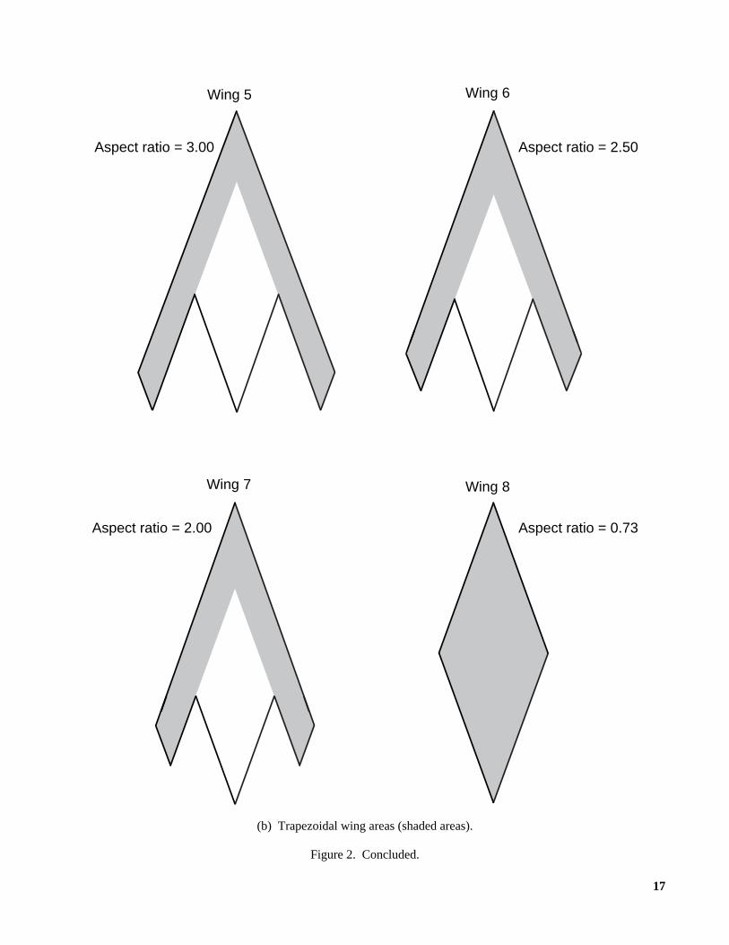
Four flying-wing models (three arrow-wing plan-forms and one diamond planform) that each had leadingedges, trailing edges, and control surface hinge linesswept at 70° (fig. 2) were tested. Given the relativelyhigh sweep angle, initial sizing analysis indicated thatarrow wings with aspect ratios between 2.0 and 3.0 couldproduce viable configurations. As a result, aspect ratiosof 3.0 (Wing 5), 2.5 (Wing 6), and 2.0 (Wing 7) werechosen for the arrow planforms (figs. 3 to 5). A set ofarrow wings swept 60° (Wings 1, 2, and 3) and a set ofarrow wings swept 50° (Wings 9, 10, and 11) with thesesame aspect ratios were tested previously (refs. 1 and 2,respectively). Unlike the aerodynamic data that werenondimensionalized with the entire planform area, theseaspect ratios were computed by using the trapezoidalareas shown in figure 2(b). For Wing 5, the three aftmostpoints on the planform extended back the same distance(fig. 3). During formulation of the remaining planforms,the overall length was held constant, and the trapezoidalareas of Wings 6 and 7 were made approximately equalto that of Wing 5. Consequently, as aspect ratio wasdecreased on the arrow wings, the span was reduced andthe tip chord was increased to maintain approximatelythe same trapezoidal area. The dimensions of the dia-
Clβ
Cl∂β∂
--------
Cl( )β 5=
Cl( )β 5–=
–
10°--------------------------------------------------------
Cnβ
Cn∂β∂
---------
Cn( )β 5=
Cn( )β 5–=
–
10°----------------------------------------------------------
CYβ
CY∂β∂
---------
CY( )β 5=
CY( )β 5–=
–
10°----------------------------------------------------------
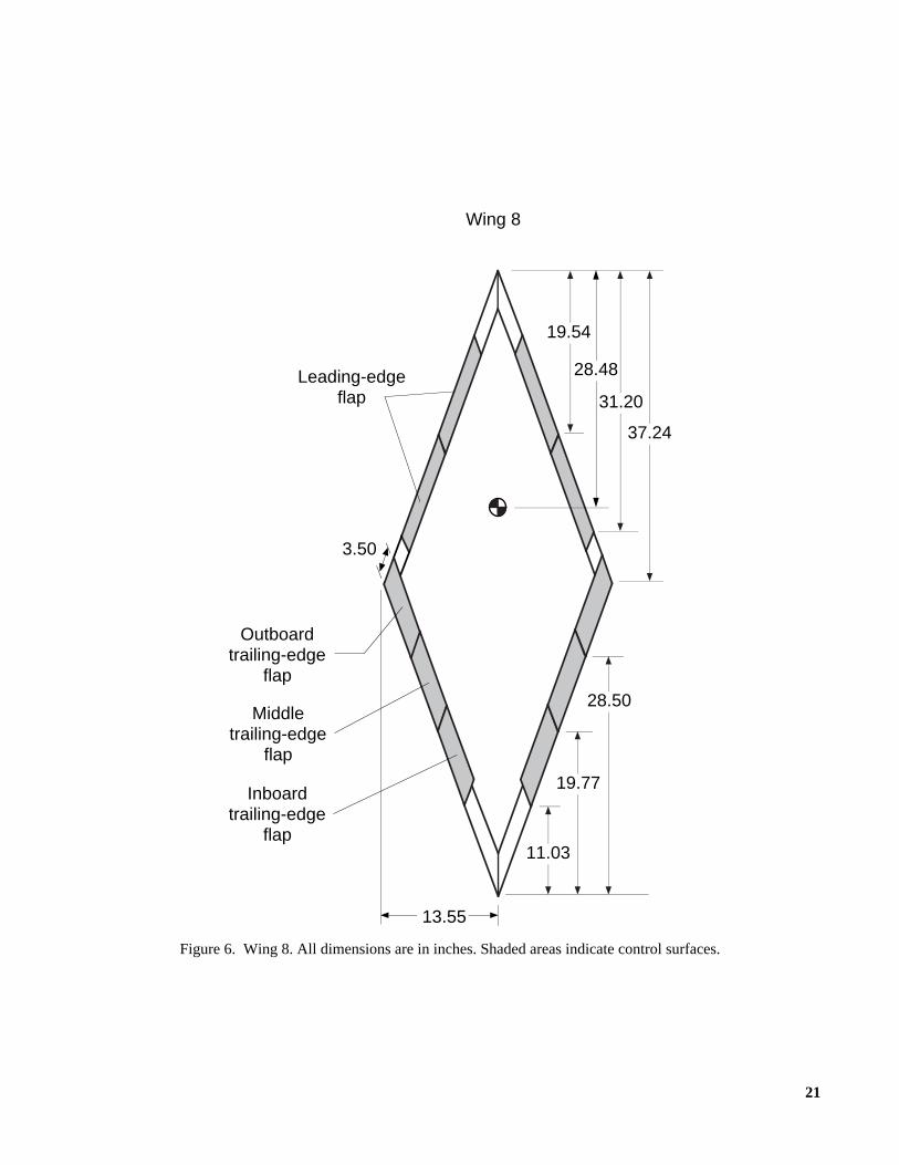
mond wing (fig. 6) were dictated by the overall lengthand the leading- and trailing-edge sweep angles andresulted in an aspect ratio of 0.73. From a geometricpoint of view, the arrow planforms can be considered tobe built up from the diamond planform by the addition ofoutboard panels having the same sweep angles as the dia-mond planform (fig. 2). Flat plate models of the basicplanforms were constructed from 3/4-in. plywood, andthe leading and trailing edges were beveled at a 13° half-angle. Table I shows the geometric characteristics foreach wing.
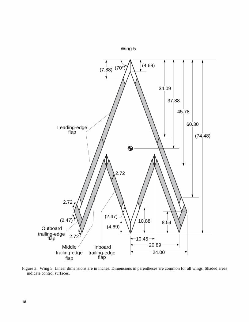
All four wings incorporated leading-edge flaps forimproved longitudinal characteristics and increased rollstability at high angles of attack. The chord length ofthese flaps was the same on all the wings, and the hingeline was located along the wing leading-edge bevel line(fig. 2). These flaps were tested at deflection angles of15°, 30°, 45°, and 60°. There were three sets of trailing-edge flaps, designated inboard (IB), middle (MID), andoutboard (OB), on each wing for roll, pitch, and yawcontrol (figs. 3 to 6). For the arrow wings, the chordlength of the trailing-edge flaps was 30 percent of thedistance between the leading and trailing edges on theoutboard section of the wing. For the diamond wing, thetrailing-edge flaps had the same chord length as those onthe low-aspect-ratio arrow wing (Wing 7). The trailing-edge flaps were deflected symmetrically (−30°, −15°,15°, and 30°) for pitch control and differentially (−30°)for roll control. Split deflection of these flaps (to be dis-cussed subsequently) was tested as a means to provideyaw control.
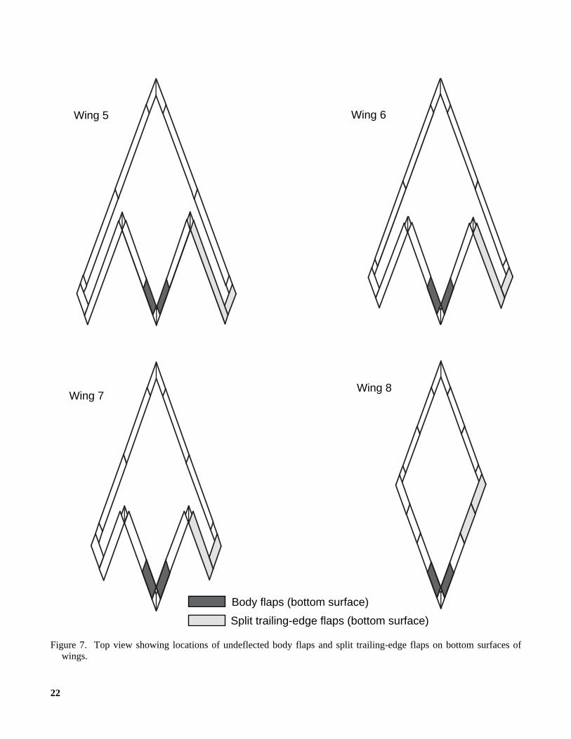
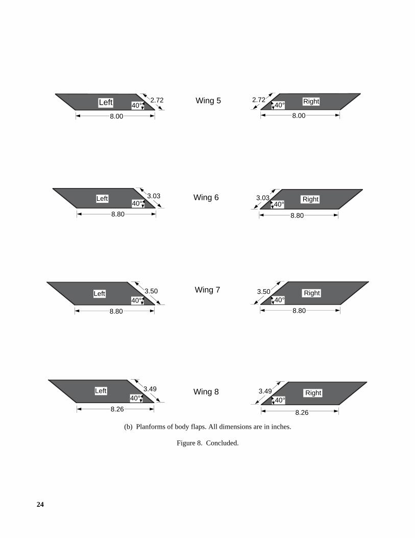
To provide supplemental nose-down pitch control,body flaps were tested by using model parts constructedof sheet metal (fig. 7). The body flaps were mounted onthe underside of the wing inboard of the trailing-edgeflaps. The inboard corners of the undeflected body flapswere positioned on the centerline with their hinge linecoinciding with the hinge line of the trailing-edge flaps(fig. 7). Symmetric downward deflections of 58° and 73°were tested on each wing. The sheet metal part modeledthe bottom surface of a beveled body flap (fig. 8).Because these models had a trailing-edge bevel half-angle of 13°, the 60° bend in the sheet metal part repre-sented a 73° deflection of the simulated beveled flap(fig. 8).
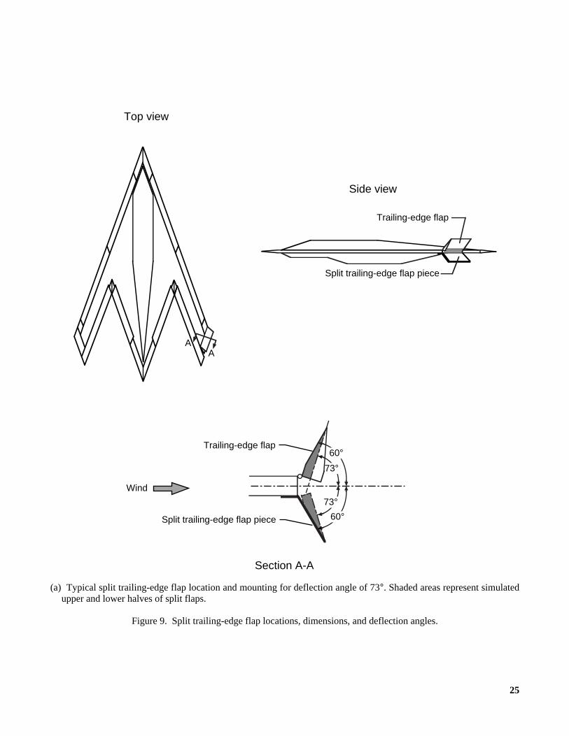
As noted previously, to provide yaw control splitdeflections of the trailing-edge flaps were tested. Thisconcept involves a given flap separating into top and bot-tom halves such that the top half deflects upward and thebottom half deflects downward. These deflections wouldbe made on the right or left wing only, thereby creatingan unbalanced drag force and an associated yawingmoment. During these tests, sheet metal pieces were
4
mounted on the underside of the wing beneath the middleor outboard trailing-edge flaps to represent the lowerhalf of a split deflection. The upper half was simulatedby deflecting the trailing-edge flap upward at the sameangle (fig. 9). The tested deflections (43° and 73°) weremeasured similar to the body flap deflections. For thesetests, the split trailing-edge flaps were tested on the rightwing.
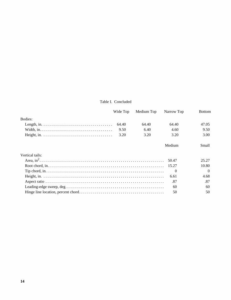
Three top body shapes were tested on the upper sur-face of each wing in conjunction with a single bottombody that covered the balance (fig. 10). Some testing wasdone without a top body, but the bottom body wasalways on the wing to shield the balance from the air-flow. The length and height of the top bodies were keptconstant, but the width was varied to obtain the three topshapes (wide, medium, and narrow). The resulting cross-sectional shapes were semielliptical for the wide andnarrow bodies and semicircular for the medium body(fig. 10). When installed, the front tip of the top bodieswas 5 in. (6.7 percent of root chord) aft of the leadingedge of the wing, and the rear tip was the same distanceforward of the wing trailing edge. The front tip of thebottom body was also 5 in. behind the leading edge, andthe rear tip was 22.43 in. (30.1 percent of root chord) for-ward of the wing trailing edge.
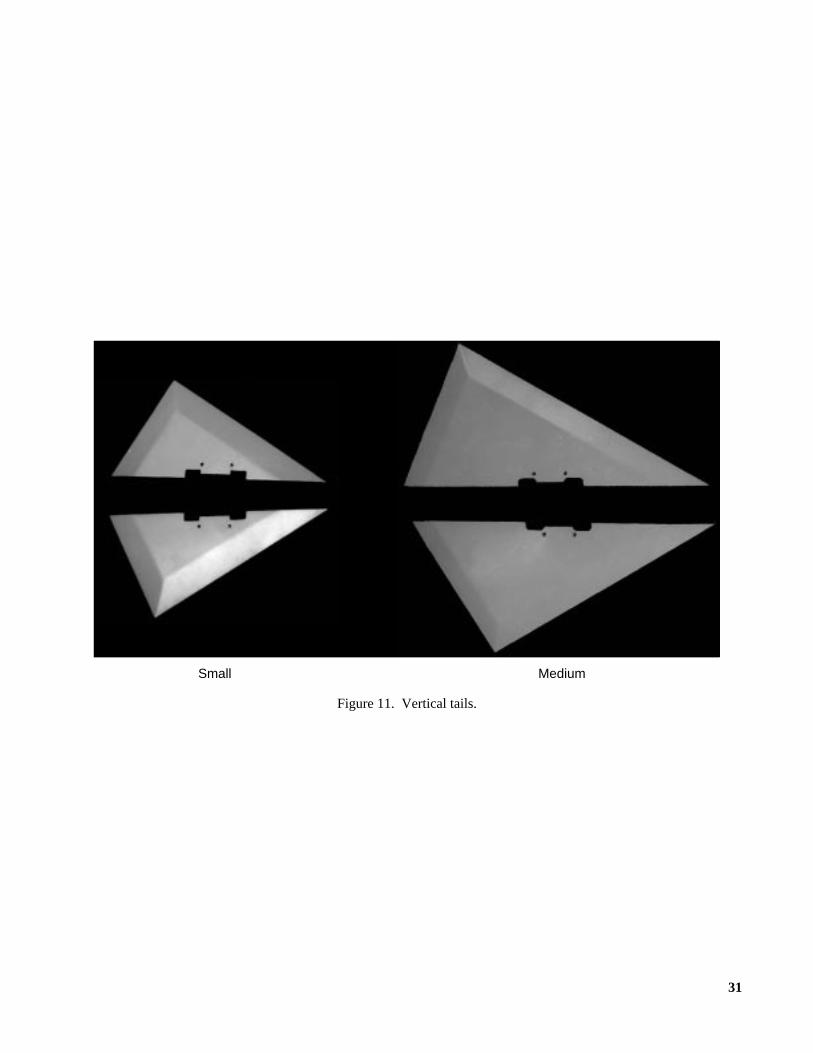
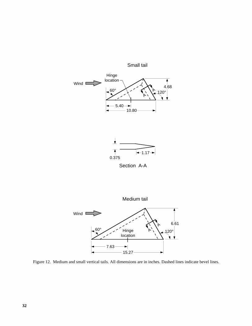
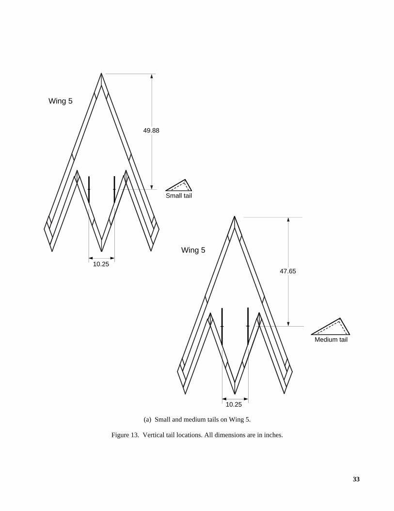
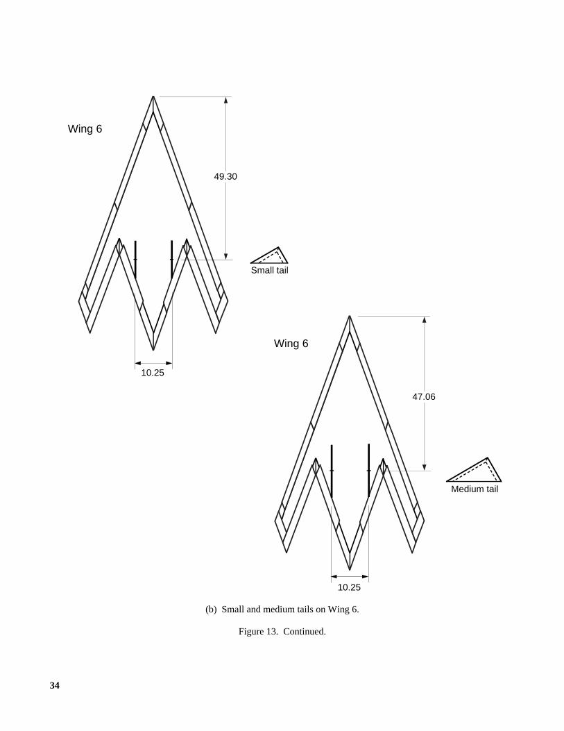
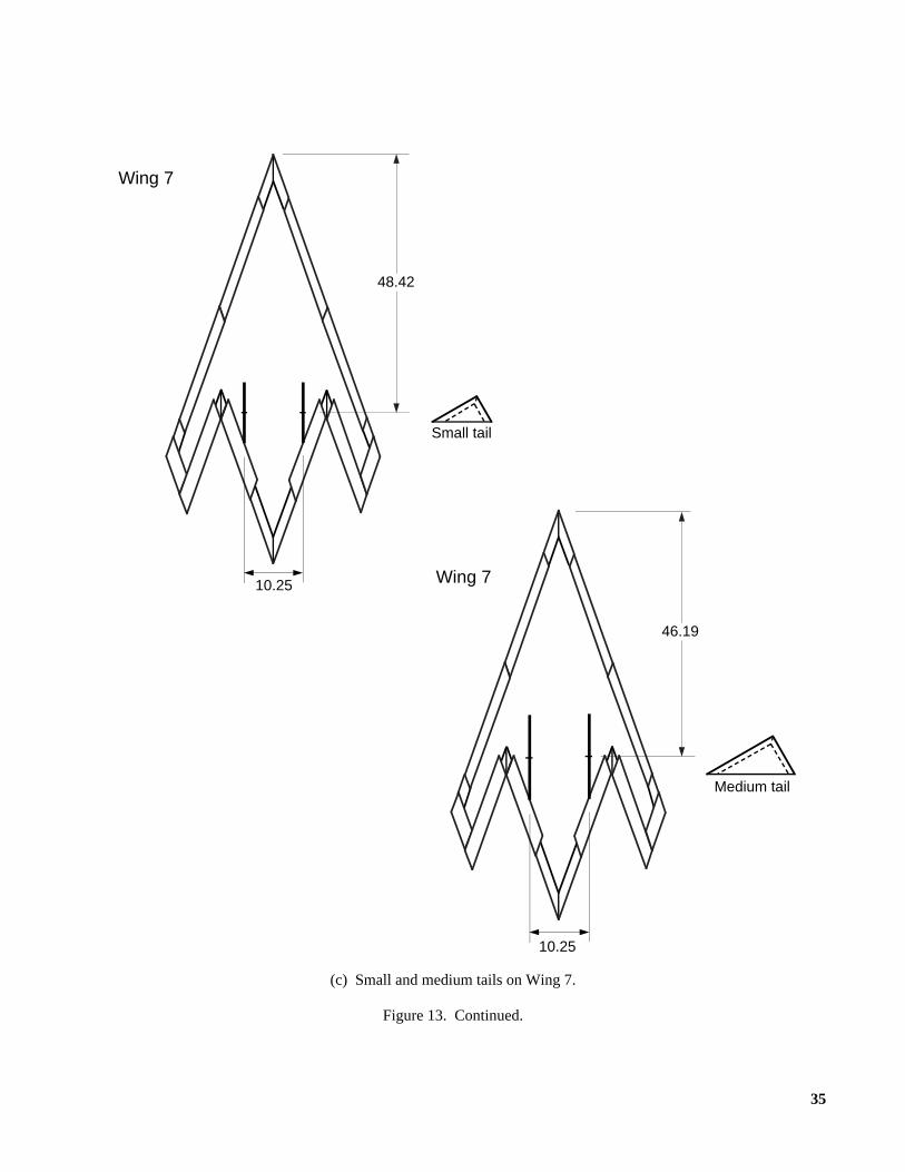
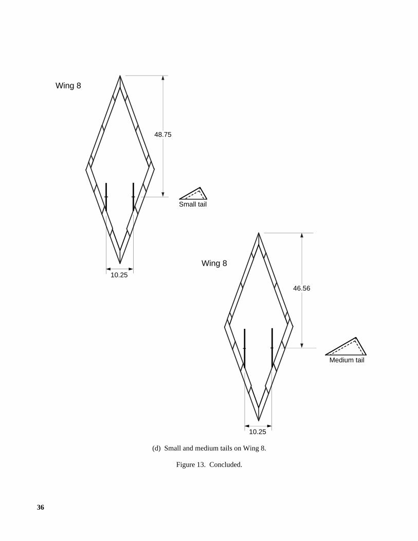
Two sets of vertical tails (small and medium) weretested (fig. 11). The planform of the tails was a 30°-60°-90° triangle with the leading edge swept 60° (fig. 12).The tails were sized such that the medium tail had twicethe area of the small tail (table I). They were mounted ina twin tail configuration with zero cant and toe angle andwere deflected as all-moving tails for directional controlabout a vertical axis located at one-half the vertical tailroot chord. On many existing reduced-RCS aircraft(F-117, YF-22, and YF-23), the tails are canted to reducetheir contributions to the total aircraft RCS from certainaspects. However, during this study, the tails wereuncanted so that the maximum levels of directional sta-bility and control available from the triangular planformscould be determined. The vertical tails were longitudi-nally positioned on the wing so that the aftmost points ofthe undeflected tails were at the wing trailing edge(fig. 13).
Test Techniques and Conditions
The aerodynamic testing was performed in theLangley 12-Foot Low-Speed Tunnel. The model andbalance were mounted in the test section on a sting andC-strut arrangement (fig. 14). The tests were conductedat a free-stream dynamic pressure of 4 lb/ft2, which cor-
responds to a test Reynolds number of 1.26× 10⁶ forWing 5, 1.29× 10⁶ for Wing 6, 1.34× 10⁶ for Wing 7,and 1.52× 10⁶ for Wing 8 based on the mean aero-dynamic chord of each wing. A six-component, inter-nally mounted strain gauge balance was used to measurethe aerodynamic loads. The static force and moment datawere measured over an angle-of-attack range of−8° to48° and over a sideslip range of−15° to 15°. The data atsideslip angles of−5° and 5° were used to calculate thelateral-directional stability derivatives ( , , and
) by means of a linear fit between these two angles.Flow upwash corrections were included during the angle-of-attack calibration, but no corrections for flow side-wash were needed. Corrections for wall effects or testsection blockage were not included.
Results and Discussion
Longitudinal Stability Characteristics
The longitudinal stability characteristics of the fourflying wings are presented in the following figures.
FigureWing planform:
Top body off,δLEF = 0° . . . . . . . . . . . . . . . . . . . . . 15Top body off,δLEF = 45° . . . . . . . . . . . . . . . . . . . . 16Wide top body on,δLEF = 0° . . . . . . . . . . . . . . . . . 17Wide top body on,δLEF = 45° . . . . . . . . . . . . . . . . 18
Top bodies:δLEF = 0°:
Wing 5 . . . . . . . . . . . . . . . . . . . . . . . . . . . . . . . . 19Wing 6 . . . . . . . . . . . . . . . . . . . . . . . . . . . . . . . . 20Wing 7 . . . . . . . . . . . . . . . . . . . . . . . . . . . . . . . . 21Wing 8 . . . . . . . . . . . . . . . . . . . . . . . . . . . . . . . . 22
δLEF = 45°:Wing 5 . . . . . . . . . . . . . . . . . . . . . . . . . . . . . . . . 23Wing 6 . . . . . . . . . . . . . . . . . . . . . . . . . . . . . . . . 24Wing 7 . . . . . . . . . . . . . . . . . . . . . . . . . . . . . . . . 25Wing 8 . . . . . . . . . . . . . . . . . . . . . . . . . . . . . . . . 26
Leading-edge flap deflections:Top body off:
Wing 5 . . . . . . . . . . . . . . . . . . . . . . . . . . . . . . . . 27Wing 6 . . . . . . . . . . . . . . . . . . . . . . . . . . . . . . . . 28Wing 7 . . . . . . . . . . . . . . . . . . . . . . . . . . . . . . . . 29Wing 8 . . . . . . . . . . . . . . . . . . . . . . . . . . . . . . . . 30
Wide top body on:Wing 5 . . . . . . . . . . . . . . . . . . . . . . . . . . . . . . . . 31Wing 6 . . . . . . . . . . . . . . . . . . . . . . . . . . . . . . . . 32Wing 7 . . . . . . . . . . . . . . . . . . . . . . . . . . . . . . . . 33Wing 8 . . . . . . . . . . . . . . . . . . . . . . . . . . . . . . . . 34
ClβCnβ
CYβ
5
Vertical tails:Narrow top body on,δLEF = 45°:
Wing 5. . . . . . . . . . . . . . . . . . . . . . . . . . . . . . . . . 35Wing 6. . . . . . . . . . . . . . . . . . . . . . . . . . . . . . . . . 36Wing 7. . . . . . . . . . . . . . . . . . . . . . . . . . . . . . . . . 37Wing 8. . . . . . . . . . . . . . . . . . . . . . . . . . . . . . . . . 38
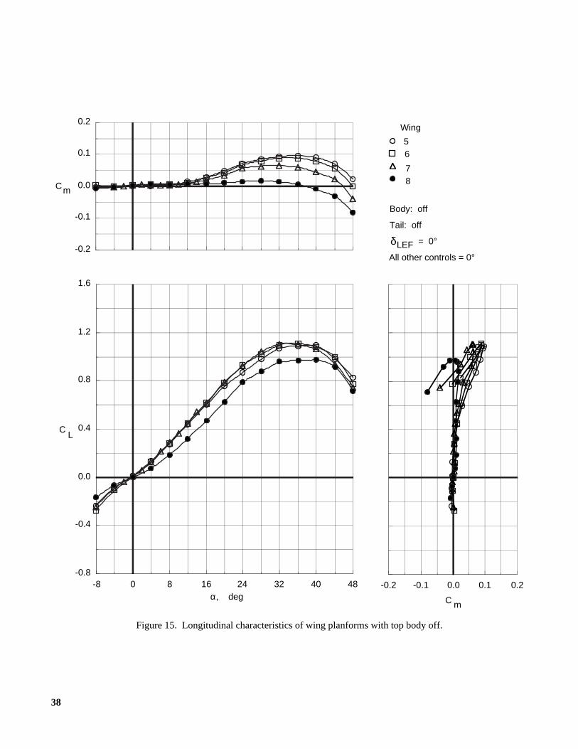
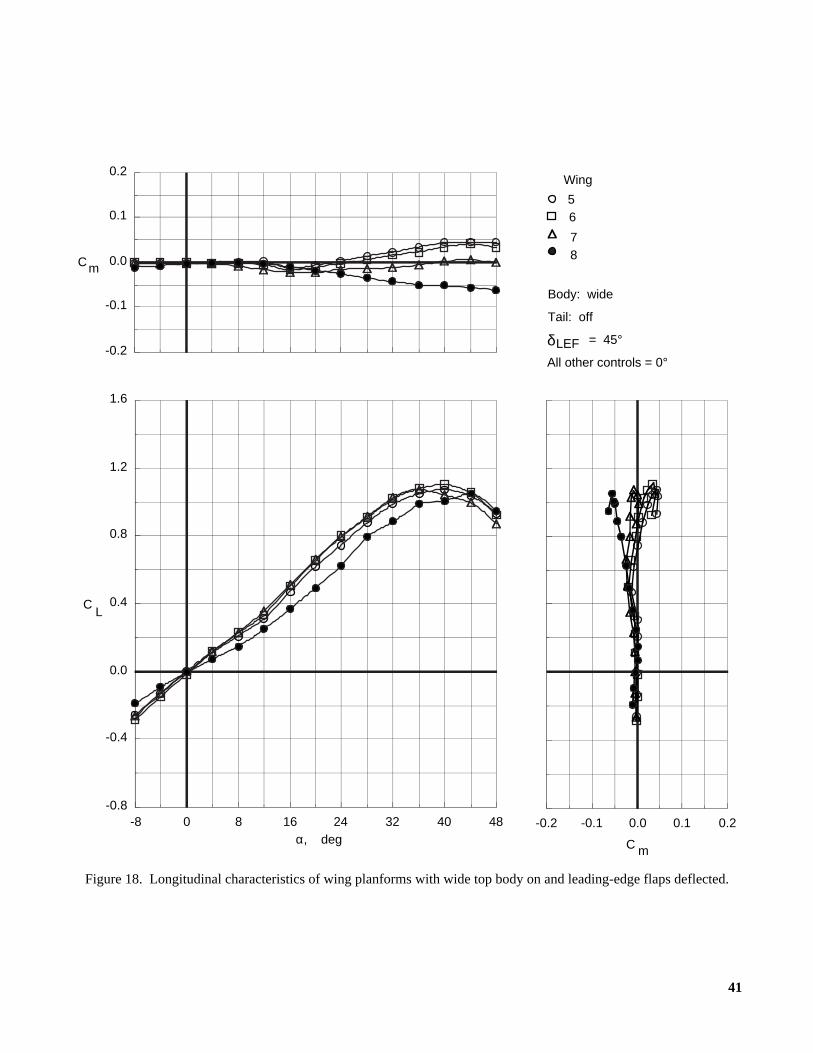
Wing planform.Comparisons of the longitudinalcharacteristics of the four wings with the leading-edgeflaps deflected and undeflected with the wide top bodyon and off are presented in figures 15 to 18. In general,the maximum lift coefficient was about 1.1 for the arrowwings (α ≈ 36°) and about 1.0 for the diamond wing(α ≈ 40°). The lift curve slopes of the arrow wings (trap-ezoidal aspect ratios of 3.0, 2.5, and 2.0, which corre-spond to Wings 5, 6, and 7, respectively) were fairlysimilar. However, the lift curve slope of the diamondwing (aspect ratio of 0.73, Wing 8) was considerablylower at angles of attack below 8°. Therefore, the dia-mond wing yielded a lower lift coefficient at a givenangle of attack than the arrow wings for angles of attackbelow maximum lift.
As mentioned previously, the moment reference cen-ters (figs. 3 to 6 and table I) were chosen so that eachconfiguration with the wide top body on (fig. 17) wouldhave neutral longitudinal stability at angles of attacknear 0° when all the controls were undeflected. Thearrow wings experienced a pitch-up for angles of attackbetween 10° and 18° (depending on planform andleading-edge flap deflection), and the effects of pitch-upbecame larger as the aspect ratio increased. For theseplanforms, larger aspect ratios were obtained by addingoutboard wing panels of increasing size to the basic dia-mond shape. Previous studies have shown that the onsetof separation on the outboard portions of swept wingscontributes to a reduction in longitudinal stability that issometimes called pitch-up (refs. 3 and 4). For this reason,the wings with the higher aspect ratios were more sus-ceptible to pitch-up effects because the outboard portionsof the wings were larger and farther aft (behind theMRC). In contrast, the diamond wing, which did nothave these outboard wing panels, actually experienced aslight pitch-down at comparable angles of attack.
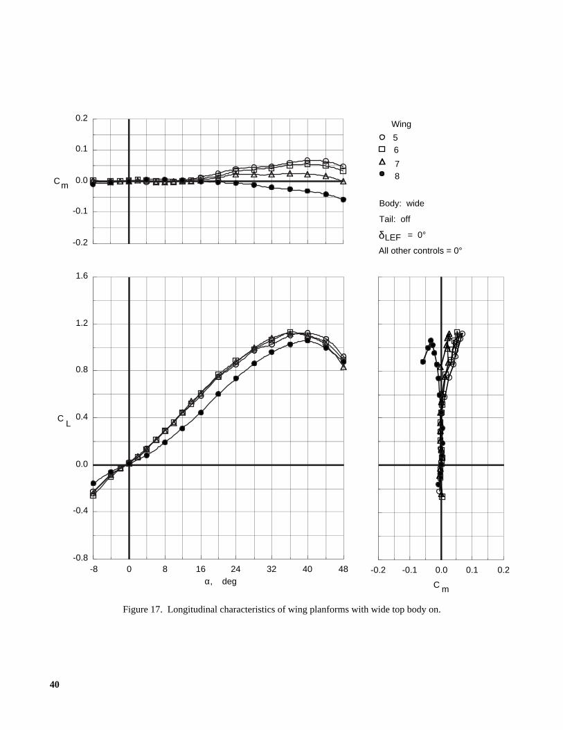
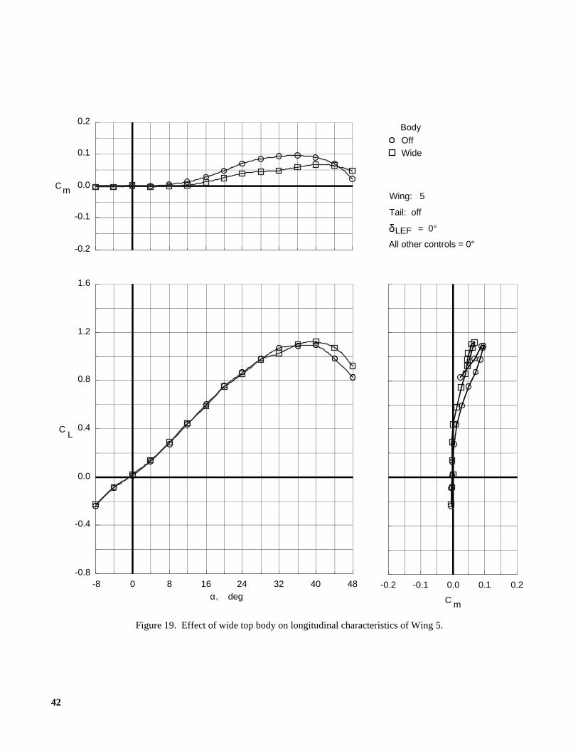
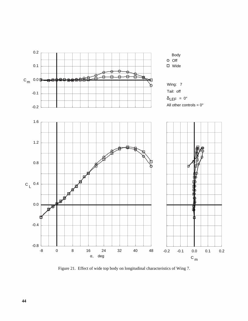
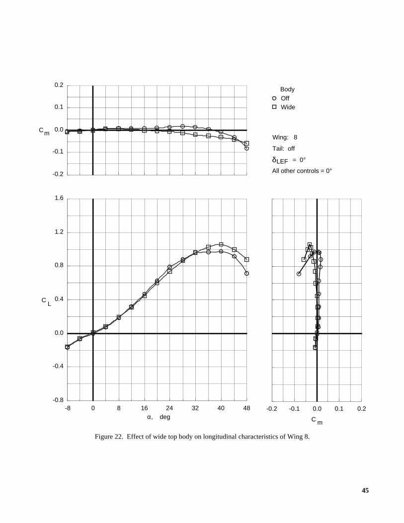
Top bodies.The effect of the various top bodies(fig. 10) on the longitudinal characteristics of the differ-ent wings is shown in figures 19 to 26. With the leading-edge flaps undeflected, the models were tested with thetop body off and with the wide body on (figs. 19 to 22).Adding the wide top body generally reduced lift at anglesof attack below and near maximum lift. Above maximumlift, lift was increased by adding the wide top body. Theangle of attack for maximum lift was also slightly
increased when the wide top body was used. Adding ofthe wide top body resulted in a nose down increment inpitching moment for each of the wings. As a result, theonset of the pitch-up of the arrow wings was delayed,and the magnitude of the resulting pitching moment wasdecreased.
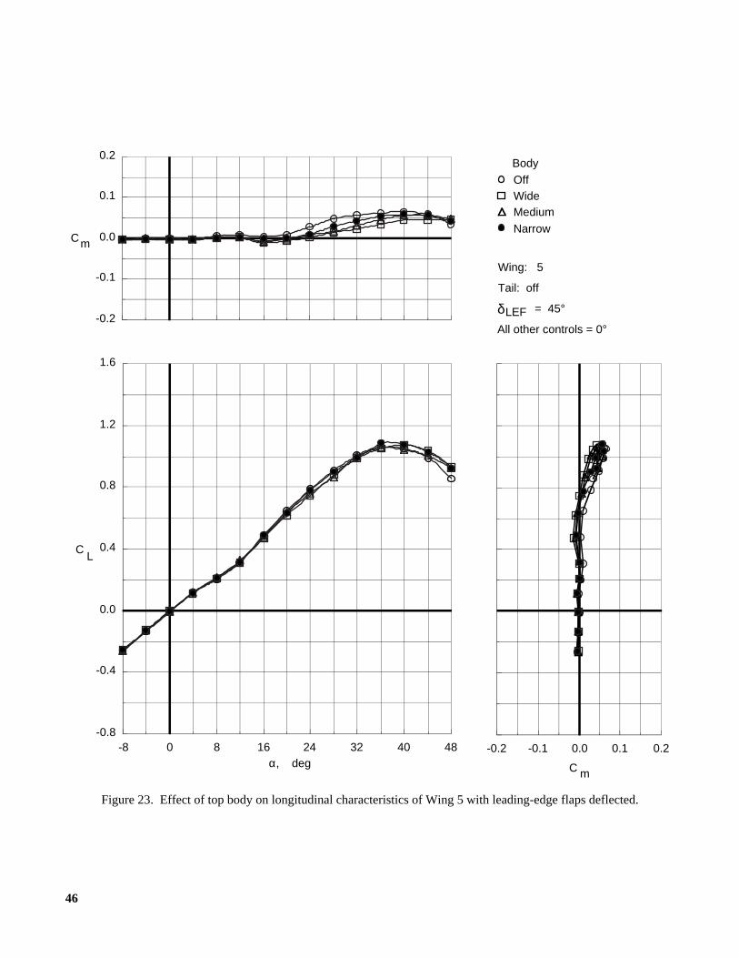
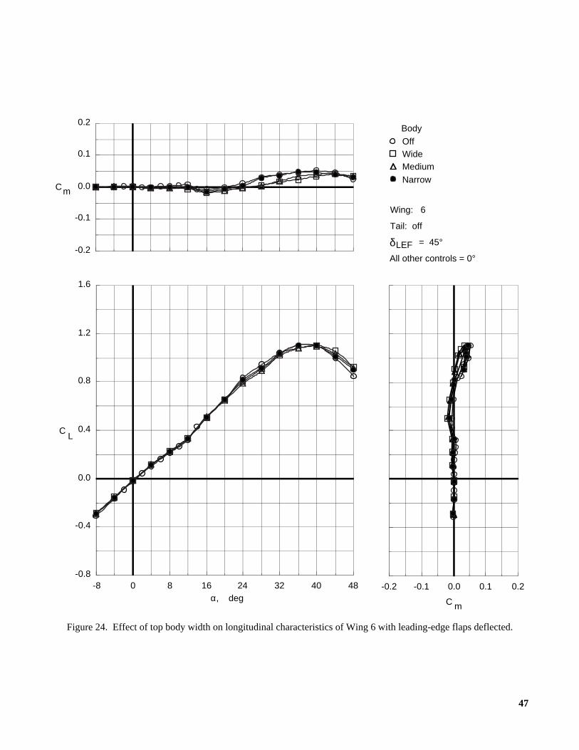
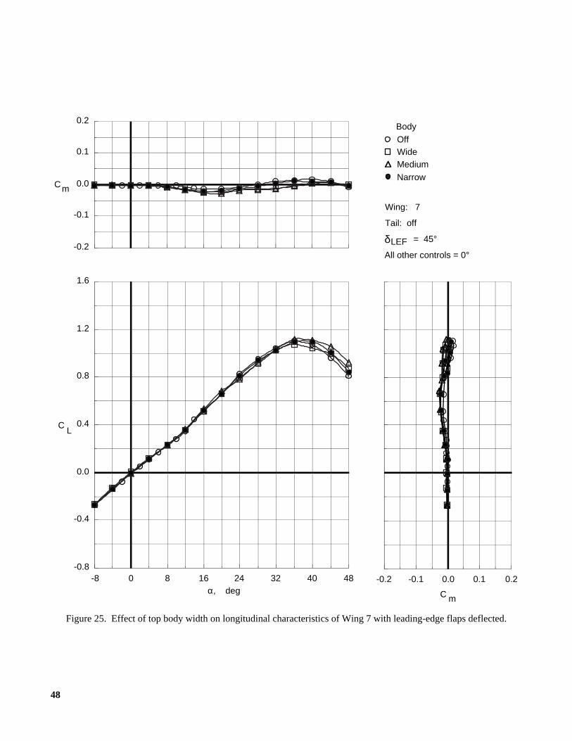
With the leading-edge flaps deflected 45°, the mod-els were tested with the top body removed and with eachof the three top bodies (figs. 23 to 26). In general, theeffect of the bodies on lift and pitching moment weresimilar to, but smaller in magnitude than, the effects thatoccurred when the leading-edge flaps were undeflected.As the body width was increased, the magnitude of thenose-down pitching-moment increment increased.
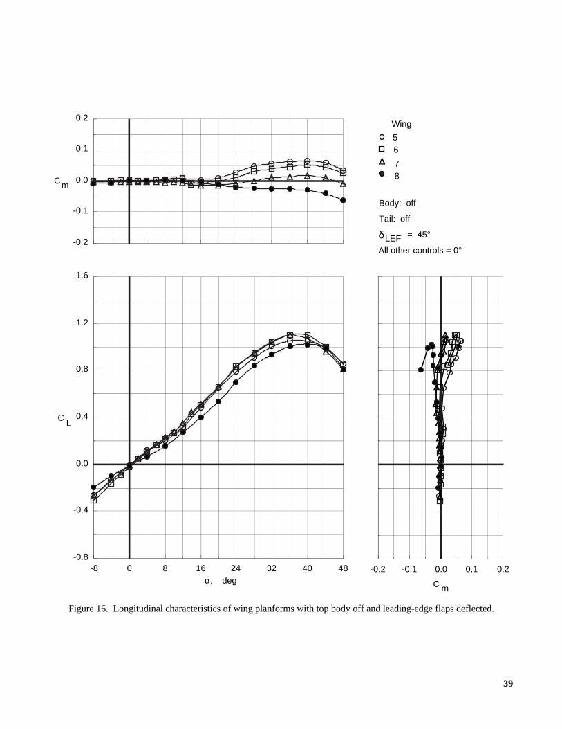
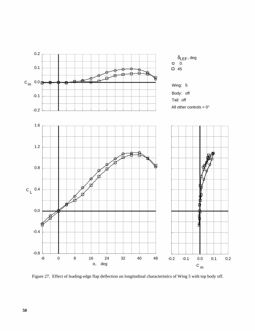
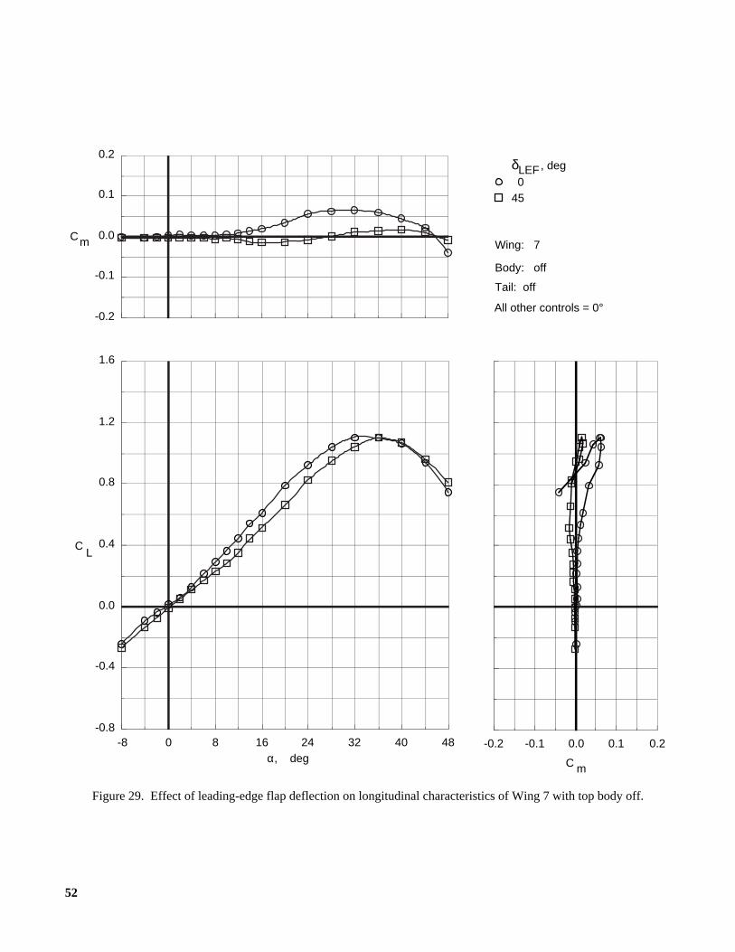
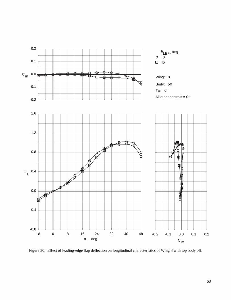
Leading-edge flap deflections.The effect of deflec-tions of the leading-edge flaps on the longitudinal char-acteristics of the different wings is shown in figures 27to 34. Data are shown for the four planforms with the topbody removed in figures 27 to 30 (δLEF = 0° and 45°)and with the wide top body on in figures 31 to 34(δLEF = 0°, 15°, 30°, 45°, and 60°). The data show a typ-ical effect of leading-edge flap deflections on very highlyswept wings (ref. 4). For most of the configurations,deflecting these flaps reduced the lift coefficient atangles of attack below maximum lift. A nose-downpitching-moment increment was associated with thesereductions in lift, reducing the effects of the pitch-up onthe arrow wings. This pitching-moment increment alsoincreased the angle of attack at which the arrow wingsbegan to experience pitch-up effects by about 8°. Theeffects of leading-edge flap deflections on both lift andpitching moment were increased by using larger deflec-tion angles.
Vertical tails.Figures 35 to 38 show the effect of thetwin vertical tails (figs. 11 to 13) on the longitudinalcharacteristics of the four configurations with the narrowtop body on and the leading-edge flaps deflected 45°.Adding the vertical tails reduced lift coefficient nearmaximum lift for each of the wings. This lift reductionwas possibly due to the tails interfering with the leading-edge vortical flow on the upper surfaces of the wings,causing these vortices to burst prematurely at the higherangles of attack. A flow field investigation (flow visual-ization, laser Doppler velocimeter, pressure measure-ments, etc.) would be required to make this determi-nation. The lift was further reduced as the size of thevertical tails was increased.
Longitudinal Control Characteristics
The longitudinal control characteristics of the fourflying wings are presented in the following figures.

6
FigureInboard trailing-edge flaps:
Wide top body on,δLEF = 45°:Wing 5. . . . . . . . . . . . . . . . . . . . . . . . . . . . . . . . . 39Wing 6. . . . . . . . . . . . . . . . . . . . . . . . . . . . . . . . . 40Wing 7. . . . . . . . . . . . . . . . . . . . . . . . . . . . . . . . . 41Wing 8. . . . . . . . . . . . . . . . . . . . . . . . . . . . . . . . . 42
Middle trailing-edge flaps:Wide top body on,δLEF = 45°:
Wing 5. . . . . . . . . . . . . . . . . . . . . . . . . . . . . . . . . 43Wing 6. . . . . . . . . . . . . . . . . . . . . . . . . . . . . . . . . 44Wing 7. . . . . . . . . . . . . . . . . . . . . . . . . . . . . . . . . 45Wing 8. . . . . . . . . . . . . . . . . . . . . . . . . . . . . . . . . 46
Inboard and middle trailing-edge flaps:Wide top body on:
Wing 5,δLEF = 0° . . . . . . . . . . . . . . . . . . . . . . . . 47Wing 5,δLEF = 45° . . . . . . . . . . . . . . . . . . . . . . . 48Wing 6,δLEF = 45° . . . . . . . . . . . . . . . . . . . . . . . 49Wing 7,δLEF = 0° . . . . . . . . . . . . . . . . . . . . . . . . 50Wing 7,δLEF = 45° . . . . . . . . . . . . . . . . . . . . . . . 51Wing 8,δLEF = 0° . . . . . . . . . . . . . . . . . . . . . . . . 52Wing 8,δLEF = 45° . . . . . . . . . . . . . . . . . . . . . . . 53
Maximum nose-down control:Wide top body on,δLEF = 45°:
Wing 5. . . . . . . . . . . . . . . . . . . . . . . . . . . . . . . . . 54Wing 6. . . . . . . . . . . . . . . . . . . . . . . . . . . . . . . . . 55Wing 7. . . . . . . . . . . . . . . . . . . . . . . . . . . . . . . . . 56Wing 8. . . . . . . . . . . . . . . . . . . . . . . . . . . . . . . . . 57
Inboard trailing-edge flaps.The longitudinal con-trol effectiveness of symmetric deflections of the inboardtrailing-edge flaps is shown in figures 39 to 42. At anglesof attack below 8°, these flaps were essentially ineffec-tive for longitudinal control. Above this angle of attack,these flaps produced small nose-up control increments onthe arrow wings and small amounts of nose-up and nose-down control on the diamond wing. These results indi-cated a potential pitch-up problem for these configura-tions. The lack of nose-down control effectiveness couldlimit the maximum trim angle of attack if nose-downcontrol was required for trim at the higher angles ofattack, depending on the longitudinal stability level ofthe final design. The aforementioned insufficient controlpower combined with a stable, deep stall trim conditioncould result in a hung stall (fig. 41).
Middle trailing-edge flaps.Figures 43 to 46 showthe longitudinal control effectiveness of symmetricdeflections of the middle trailing-edge flaps. As with theinboard flaps, the middle flaps were essentially ineffec-tive for longitudinal control at low angles of attack, butsmall amounts of nose-up control were produced by neg-ative deflections at the higher angles of attack. These
control increments were smaller than those produced bythe marginally effective inboard flaps on the arrowwings, despite the fact that the middle flaps were largerthan the inboard flaps and had a longer longitudinalmoment arm. For the diamond wing, the middle flapsproduced slightly more lift than the inboard flaps, butthere was less longitudinal control because the longitudi-nal moment arm of the middle flaps was shorter than thatof the inboard flaps.
Inboard and middle trailing-edge flaps.The longi-tudinal control effectiveness produced when the inboardand middle trailing-edge flaps were deflected symmetri-cally is shown in figures 47 to 53. As with the individualdeflections, these combined flap deflections producedminimal effectiveness at the lower angles of attack andmoderate nose-up control effectiveness at the higherangles of attack. Nose-up control effectiveness at theintermediate deflections tested was relatively linear overmost of the angle-of-attack range. For Wings 5, 7, and 8,multiple trailing-edge flap deflections were tested withthe leading-edge flaps undeflected and deflected 45°.Deflecting the leading-edge flaps 45° did not signifi-cantly affect the control effectiveness produced by multi-ple deflections of the inboard and middle trailing-edgeflaps.
Multiple symmetric deflections of the inboard andmiddle trailing-edge flaps involved moving a significantportion of the total wing area allocated for control.Despite this large area, the longitudinal control effective-ness was very small, especially in the nose-down direc-tion. It should be noted that each of the wings could bestatically trimmed over a large angle-of-attack rangewhen the effect of the pitch-up was reduced by leading-edge flap deflections. However, additional pitch controlpower would likely be needed to provide these wingswith sufficient control margin for situations such asmaneuvering or countering turbulence (ref. 5). An addi-tional limit on the pitch control provided by the flapsmay be imposed by the need to budget the amount of flapdeflection available for each type of control (pitch, roll,or yaw). If some portion of the total flap travel must bereserved for roll or yaw control, the remaining amountavailable for pitch control will be less than the maxi-mum. For these reasons, these configurations wouldprobably require redesigned flaps or additional pitch con-trol devices to achieve desired levels of pitch control.
Maximum nose-down control.In addition to thetrailing-edge flaps, each configuration also had bodyflaps on the bottom surface of the wing (fig. 8) that wereintended to provide supplemental nose-down pitch con-trol. The body flaps were deflected in combination withnose-down deflections of the trailing-edge flaps, and the
7
data are presented in figures 54 to 57. Deflections ofthe body flaps provided a small nose-down pitchingincrement that was relatively constant throughout theangle-of-attack range. Deflecting the body flaps from 58°to 73° did not produce any additional nose-down control.Symmetric deflections of the relatively small outboardtrailing-edge flaps did not significantly increase the over-all level of longitudinal control.
Lateral-Directional Stability Characteristics
The lateral-directional aerodynamics and stabilitycharacteristics of the four flying wings are presented inthe following figures.
FigureSideslip:
Wing 5, wide top body on:δLEF = 0°, low angles of attack . . . . . . . . . . . . . . 58δLEF = 0°, high angles of attack . . . . . . . . . . . . . 59δLEF = 45°, low angles of attack . . . . . . . . . . . . . 60δLEF = 45°, high angles of attack . . . . . . . . . . . . 61
Wing 6, wide top body on:δLEF = 0°, low angles of attack . . . . . . . . . . . . . . 62δLEF = 0°, high angles of attack . . . . . . . . . . . . . 63δLEF = 45°, low angles of attack . . . . . . . . . . . . . 64δLEF = 45°, high angles of attack . . . . . . . . . . . . 65
Wing 7, wide top body on:δLEF = 0°, low angles of attack . . . . . . . . . . . . . . 66δLEF = 0°, high angles of attack . . . . . . . . . . . . . 67δLEF = 45°, low angles of attack . . . . . . . . . . . . . 68δLEF = 45°, high angles of attack . . . . . . . . . . . . 69
Wing 8, wide top body on:δLEF = 0°, low angles of attack . . . . . . . . . . . . . . 70δLEF = 0°, high angles of attack . . . . . . . . . . . . . 71δLEF = 45°, low angles of attack . . . . . . . . . . . . . 72δLEF = 45°, high angles of attack . . . . . . . . . . . . 73
Wing planform:Top body off,δLEF = 0°. . . . . . . . . . . . . . . . . . . . . . 74Top body off,δLEF = 45°. . . . . . . . . . . . . . . . . . . . . 75Wide top body on,δLEF = 0° . . . . . . . . . . . . . . . . . . 76Wide top body on,δLEF = 45° . . . . . . . . . . . . . . . . . 77
Top bodies:δLEF = 0°:
Wing 5. . . . . . . . . . . . . . . . . . . . . . . . . . . . . . . . . 78Wing 6. . . . . . . . . . . . . . . . . . . . . . . . . . . . . . . . . 79Wing 7. . . . . . . . . . . . . . . . . . . . . . . . . . . . . . . . . 80Wing 8. . . . . . . . . . . . . . . . . . . . . . . . . . . . . . . . . 81
δLEF = 45°:Wing 5. . . . . . . . . . . . . . . . . . . . . . . . . . . . . . . . . 82Wing 6. . . . . . . . . . . . . . . . . . . . . . . . . . . . . . . . . 83Wing 7. . . . . . . . . . . . . . . . . . . . . . . . . . . . . . . . . 84Wing 8. . . . . . . . . . . . . . . . . . . . . . . . . . . . . . . . . 85
Leading-edge flap deflections:Top body off:
Wing 5 . . . . . . . . . . . . . . . . . . . . . . . . . . . . . . . . 86Wing 6 . . . . . . . . . . . . . . . . . . . . . . . . . . . . . . . . 87Wing 7 . . . . . . . . . . . . . . . . . . . . . . . . . . . . . . . . 88Wing 8 . . . . . . . . . . . . . . . . . . . . . . . . . . . . . . . . 89
Wide top body on:Wing 5 . . . . . . . . . . . . . . . . . . . . . . . . . . . . . . . . 90Wing 6 . . . . . . . . . . . . . . . . . . . . . . . . . . . . . . . . 91Wing 7 . . . . . . . . . . . . . . . . . . . . . . . . . . . . . . . . 92Wing 8 . . . . . . . . . . . . . . . . . . . . . . . . . . . . . . . . 93
Vertical tails:Narrow top body on,δLEF = 45°:
Wing 5 . . . . . . . . . . . . . . . . . . . . . . . . . . . . . . . . 94Wing 6 . . . . . . . . . . . . . . . . . . . . . . . . . . . . . . . . 95Wing 7 . . . . . . . . . . . . . . . . . . . . . . . . . . . . . . . . 96Wing 8 . . . . . . . . . . . . . . . . . . . . . . . . . . . . . . . . 97
Sideslip.The lateral-directional force and momentcoefficients of the four wings with the wide top body onare presented in figures 58 to 73 as a function of sideslipat various angles of attack and leading-edge flap deflec-tions. In general, for each of the wings the coefficientsvaried linearly with sideslip for angles between−5°and 5°. At sideslip angles outside of this range, the varia-tion in the lateral-directional coefficients became less lin-ear on many of the configurations, especially at thehigher angles of attack where some portion of the wingswas most likely experiencing extensive flow separation.These trends were not significantly affected by leading-edge flap deflections.
Wing planform. Comparisons of the lateral-directional stability characteristics (computed betweensideslip angles of−5° and 5°) of the four wings with theleading-edge flaps deflected and undeflected with thewide top body on and off are presented in figures 74to 77. Note that the data are for the configurationswithout vertical tails, and therefore each of these wingspossessed unstable or essentially neutral values of direc-tional stability ( ) at angles of attack below maximumlift. At angles of attack near maximum lift, a region ofdirectional instability of larger magnitude occurred oneach of the wings.
Each of these wings was laterally stable (negative) for most of the angles of attack tested. However, the
lateral stability was reduced at angles of attack near max-imum lift, and configurations with leading-edge flapdeflections of 45° were laterally unstable for part of thisrange of angle of attack. This phenomenon is a well-documented characteristic of highly swept wings thatis due primarily to asymmetric breakdown of the wingleading-edge vortices at sideslip (ref. 6). Changes in
Cnβ
Clβ
8
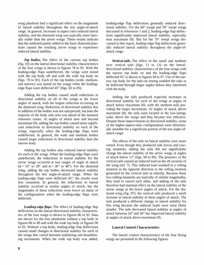
wing planform had a significant effect on the magnitudeof lateral stability throughout the test angle-of-attackrange. In general, increases in aspect ratio reduced lateralstability, and the diamond wing was typically more later-ally stable than the arrow wings. These results indicatethat the outboard panels added to the basic diamond plan-form caused the resulting arrow wings to experiencereduced lateral stability.
Top bodies.The effect of the various top bodies(fig. 10) on the lateral-directional stability characteristicsof the four wings is shown in figures 78 to 85. With theleading-edge flaps undeflected, the wings were testedwith the top body off and with the wide top body on(figs. 78 to 81). Each of the top bodies (wide, medium,and narrow) was tested on the wings when the leading-edge flaps were deflected 45° (figs. 82 to 85).
Adding the top bodies caused small reductions indirectional stability on all of the wings at the lowerangles of attack, with the largest reduction occurring onthe diamond wing. Reduction of directional stability dueto addition of the bodies was not unexpected, because themajority of the body side area was ahead of the momentreference center. At angles of attack near and beyondmaximum lift, adding the top bodies caused more signifi-cant reductions in directional stability on each of thewings, especially when the leading-edge flaps wereundeflected. In general, the wide and medium bodiescaused larger reductions in directional stability than thenarrow body.
Adding the top bodies also reduced lateral stabilityfor each of the wings. When the leading-edge flaps wereundeflected, the reductions in lateral stability for thearrow wings occurred at two ranges of angle of attack(α = 16° to 28° and α = 36° to 48°). For the diamondwing, adding the top bodies decreased lateral stabilitythroughout the test angle-of-attack range. When theleading-edge flaps were deflected 45°, the results wereless consistent. In general, the reductions in lateralstability occurred at similar angles of attack, but themagnitudes of these reductions were lower on many ofthe configurations when the leading-edge flaps weredeflected.
Leading-edge flaps.The effect of leading-edge flapdeflections on the lateral-directional stability characteris-tics of the four wings is shown in figures 86 to 93. Dataare shown for the four planforms without a top body infigures 86 to 89 and with the wide top body in figures 90to 93. Without a top body, leading-edge flap deflectionscaused small changes in directional stability for each ofthe wings that varied between stabilizing and destabiliz-ing increments. When the wide top body was added,
leading-edge flap deflections generally reduced direc-tional stability. For the 60° swept and 50° swept wingsdiscussed in references 1 and 2, leading-edge flap deflec-tions significantly improved lateral stability, especiallynear maximum lift. But for the 70° swept wings dis-cussed in this report, leading-edge flap deflections gener-ally reduced lateral stability throughout the angle-of-attack range.
Vertical tails.The effect of the small and mediumtwin vertical tails (figs. 11 to 13) on the lateral-directional stability characteristics of the four wings withthe narrow top body on and the leading-edge flapsdeflected 45° is shown in figures 94 to 97. Use of the nar-row top body for the tails-on testing enabled the tails tobe deflected through larger angles before they interferedwith the body.
Adding the tails produced expected increases indirectional stability for each of the wings at angles ofattack below maximum lift, with the medium tails pro-viding the larger increments. At angles of attack abovemaximum lift, the tails were located in the low-energywake above the wings and thus became less effective.Despite these improvements in directional stability, someof the higher-aspect-ratio configurations were direction-ally unstable for a significant portion of the test angle-of-attack range.
The effects of the tails on lateral stability were morevaried. Even though they produced side forces and yaw-ing moments, adding the tails did not significantlychange the lateral stability of the arrow wings at anglesof attack below 12° (figs. 94 to 96). The presence of thevertical tails caused an induced load on the aft sections ofthe wing (ref. 7). This induced load resulted in a rollingmoment in the opposite direction to the rolling momentgenerated by the vertical tails in sideslip. Because thesetwo rolling moments are typically of similar magnitudes,they tend to cancel each other, and adding of the tailstherefore had minimal effect on the lateral stability of thearrow wings at the lower angles of attack. For the dia-mond wing (fig. 97), the vertical tails produced a smallincrease in lateral stability at these angles of attack. Thetails produced a different change in lateral stability forthis wing because the induced loads were most likelysmaller. The tails decreased lateral stability at angles ofattack between 24° and 36° but improved lateral stabilityat angles of attack above maximum lift.
Lateral Control Characteristics
The lateral control characteristics of the four flyingwings are presented in the following figures.

9
FigureInboard, middle, and outboard trailing-edge flaps:
Wide top body on,δLEF = 45°:Wing 5. . . . . . . . . . . . . . . . . . . . . . . . . . . . . . . . . 98Wing 6. . . . . . . . . . . . . . . . . . . . . . . . . . . . . . . . . 99Wing 7. . . . . . . . . . . . . . . . . . . . . . . . . . . . . . . . 100Wing 8. . . . . . . . . . . . . . . . . . . . . . . . . . . . . . . . 101
The lateral controls tested consisted of differentialdeflections of the inboard, middle, and outboard trailing-edge flaps. On each of the wings, the middle andoutboard flaps were tested deflected separately and incombination. The inboard flaps were deflected separatelyon Wings 5 and 8, and deflected with the middle flaps onWings 5, 6, and 7. Figures 98 to 101 show the lateralcontrol effectiveness of various differential flap deflec-tions on each of the wings with the leading-edge flapsdeflected 45° and the wide top body on.
Differential deflections of the trailing-edge flaps oneach of the wings produced small rolling-moment incre-ments that were fairly invariant with changes in angle ofattack. Comparison of the control effectiveness gener-ated by the various flaps showed that the roll-controleffectiveness did not vary significantly among the flaps,despite the relatively large differences in flap area andlateral moment arm. In general, for high angles of attackthe total roll control available from multiple flap deflec-tions was equal to or less than that required to trim outthe adverse rolling moments induced by vertical taildeflections. As a result, the lateral-directional maneuver-ing capability of these wings could possibly be limitedby this relatively low level of total roll-control effective-ness. More in-depth dynamic analysis, which wasbeyond the scope of this study, would be required tomake this determination.
For the arrow wings, differential deflections of theinboard and outboard trailing-edge flaps yielded negligi-ble yawing moments. But beginning at an angle of attackof approximately 4°, deflections of the middle flapsproduced adverse yawing moments that became quitelarge at the higher angles of attack. For the diamondwing, all the differential deflections produced smallproverse yawing moments. These results show that theflaps with a forward-swept hinge line (inboard and out-board flaps on the arrow wings and all the flaps on thediamond wing) produced predominantly small proverseyawing moments, but flaps with a rearward-swept hingeline (middle flaps on the arrow wings) produced signifi-cant adverse yawing moments.
Directional Control Characteristics
The directional control characteristics of the four fly-ing wings are presented in the following figures.
FigureSplit trailing-edge flaps:
Wide top body on,δLEF = 45°:Outboard flaps:
Wing 5 . . . . . . . . . . . . . . . . . . . . . . . . . . . . . 102Wing 6 . . . . . . . . . . . . . . . . . . . . . . . . . . . . . 103Wing 8 . . . . . . . . . . . . . . . . . . . . . . . . . . . . . 104
Middle flaps:Wing 5 . . . . . . . . . . . . . . . . . . . . . . . . . . . . . 105Wing 6 . . . . . . . . . . . . . . . . . . . . . . . . . . . . . 106Wing 7 . . . . . . . . . . . . . . . . . . . . . . . . . . . . . 107Wing 8 . . . . . . . . . . . . . . . . . . . . . . . . . . . . . 108
Small vertical tails:Narrow top body on,δLEF = 45°:
Wing 5 . . . . . . . . . . . . . . . . . . . . . . . . . . . . . . . 109Wing 6 . . . . . . . . . . . . . . . . . . . . . . . . . . . . . . . 110Wing 7 . . . . . . . . . . . . . . . . . . . . . . . . . . . . . . . 111Wing 8 . . . . . . . . . . . . . . . . . . . . . . . . . . . . . . . 112
Medium vertical tails:Narrow top body on,δLEF = 45°:
Wing 5 . . . . . . . . . . . . . . . . . . . . . . . . . . . . . . . 113Wing 6 . . . . . . . . . . . . . . . . . . . . . . . . . . . . . . . 114Wing 7 . . . . . . . . . . . . . . . . . . . . . . . . . . . . . . . 115Wing 8 . . . . . . . . . . . . . . . . . . . . . . . . . . . . . . . 116
Two types of directional controls, split trailing-edgeflaps (figs. 7 and 9) and vertical tail deflections (figs. 12and 13), were tested on these models. As discussed in thesection “Model Description” (p. 3), the split trailing-edge flaps were designed to separate into a top half thatwould deflect upward and a bottom half that woulddeflect downward at the same angle, and they would bedeflected on only one wing at a time. The resultinggeometry would result in an unbalanced incremental dragforce on the wing that would produce an associated yaw-ing moment. The all-moving twin vertical tails weredeflected about an unswept hinge post located at the mid-point of the tail root chord.
Split trailing-edge flaps.The control effectivenessof split deflections of the right outboard trailing-edgeflaps for Wings 5, 6, and 8 with the wide top body onand a leading-edge flap deflection of 45° is shown in fig-ures 102 to 104. Split deflections of the outboard flapsproduced small yawing moments that were opposite tothose that would be expected to be generated by the dragon the split flaps. This result was due to the strong contri-bution of side force to the net yawing moments producedby these deflections (fig. 117). The forward sweep of thehinge lines on the outboard flaps and their location aft ofthe moment reference center caused these surfaces tofunction as a left rudder deflection when deflected on theright wing. For this reason, split deflections of a surfacewith a forward-swept hinge line produced rudder-like

10
side forces that generated yawing moments in the oppo-site direction to the yawing moments generated by thedrag on the device, resulting in the observed yawingmoments (fig. 117). The data for different deflectionangles showed that the−73° deflection produced largeryawing moments than the−43° deflection, but this con-trol effectiveness was not linear with deflection angle.For the highest-aspect-ratio wing (Wing 5), split deflec-tions of the outboard flaps produced negligible rollingmoments. For the other wings, these deflections pro-duced rolling moments towards the wing on which theflap was split that were due to a spoiler-like loss of lift onthe wing containing the split flap.
Figures 105 to 108 show the control effectiveness ofsplit deflections of the middle trailing-edge flaps for eachof the wings with the wide top body on and a leading-edge flap deflection of 45°. As with the outboard flaps,the middle flaps were deflected on the right wing. Splitdeflections of the middle flaps on the arrow wings pro-duced yawing moments in the opposite direction to thoseproduced by split deflections of the outboard flapsbecause of the difference in the sweep of the hinge linesbetween the middle and outboard flaps. In contrast to theforward sweep on the outboard flaps, the rearward sweepof the middle flaps on the arrow wings caused splitdeflections of these flaps to produce side forces in theopposite direction to those produced by comparabledeflections of the outboard flaps. These side forces pro-duced yawing moments in the same direction as the yaw-ing moments produced by the drag forces, resulting inhigher net yawing moments for many of the angles ofattack (fig. 117).
For the diamond wing, the forward-swept middleflaps produced larger yawing moments than those pro-duced by the outboard flaps because the middle flaps hada longer side-force moment arm. As with the outboardflaps, the data for different deflection angles showed thatthe −73° deflection produced larger yawing momentsthan the−43° deflection at some of the angles of attacktested, but this control effectiveness was not linear withdeflection angle. Also, these deflections produced prov-erse rolling moments towards the wing on which the flapwas split because of a spoiler-like loss of lift on thatwing.
Despite the improved effectiveness relative to theoutboard flaps, the levels of yaw control produced bysplit deflections of the middle flaps were relatively small,especially at the lower angles of attack. Because of thislow level of yaw-control effectiveness, the lateral-directional maneuvering potential of these configurationscould be limited. More in-depth dynamic analysis, whichwas beyond the scope of this study, would be required to
determine whether these configurations could obtain ade-quate yaw control from split deflections of the trailing-edge flaps.
Vertical tails.Figures 109 to 112 show the controleffectiveness of the small twin vertical tails for each ofthe wings when the narrow top body was used and theleading-edge flaps were deflected 45°. For each of thewings, deflections of the small tails produced yaw-control effectiveness that was relatively invariant atangles of attack below maximum lift. Above maximumlift, the yaw-control effectiveness decreased withincreasing angle of attack as the tails became located inthe low-energy wake behind the stalled wing. The−30°deflection of the small tails produced approximatelytwice the yaw-control effectiveness of the−10° deflec-tion on many of the configurations. This shows that theyaw-control effectiveness of the small tails was not linearwith deflection angle for deflections between 10°and 30°. The rolling moments produced by deflections ofthe small tails were negligible at low angles of attack onthe arrow wings, but adverse rolling moments were gen-erated at these same angles of attack on the diamondwing. For each of the wings, larger adverse rollingmoments occurred near maximum lift.
The control effectiveness of deflections of themedium twin vertical tails for each of the wings with thenarrow top body on and the leading-edge flaps deflected45° is shown in figures 113 to 116. The yaw-controleffectiveness produced by deflections of the mediumtails was generally larger than that generated by the smalltails. As with the small tails, the level of effectivenessgenerated on a given arrow wing was relatively invariantat angles of attack below maximum lift, and this effec-tiveness decayed at angles of attack above maximum lift.For the diamond wing, the medium tails began to loseeffectiveness at a lower angle of attack (approximately20°) than the small tails. The data for deflection anglesof −10° and−21° (the lower maximum deflection anglefor the medium tails resulted from body interference)indicate that the yaw-control effectiveness of the mediumtails was linear with deflection angle for deflectionangles below approximately 21°. The rolling momentsproduced by deflections of the medium tails were alsosimilar in character to, but larger in magnitude than, therolling moments produced by deflections of the smalltails. For the arrow wings, negligible rolling momentswere produced at the lower angles of attack, and signifi-cant adverse rolling moments were produced near maxi-mum lift. For the diamond wing, adverse rollingmoments were produced throughout the angle-of-attackrange with larger moments occurring near maximum lift.

11
Conclusions
A wind-tunnel investigation was conducted in theLangley 12-Foot Low-Speed Tunnel to study the low-speed stability and control characteristics of a series offour flying wings over an extended range of angle ofattack. Because of the current emphasis on reducing theradar cross section (RCS) of new military aircraft, theplanform of each wing was composed of lines swept at arelatively high angle of 70°, and all the trailing edges andcontrol surface hinge lines were aligned with one of thetwo leading edges. Three arrow planforms with differentaspect ratios and one diamond planform were tested. Themodels incorporated leading-edge flaps for improvedlongitudinal characteristics and lateral stability and hadthree sets of trailing-edge flaps that were deflected sym-metrically for pitch control, differentially for roll control,and in a split fashion for yaw control. Three top bodywidths and two sizes of twin vertical tails were alsotested on each model. A large aerodynamic database wascompiled that could be used to evaluate some of thetrade-offs involved in the design of a configuration witha reduced RCS and good flight dynamic characteristics.The results of this investigation may be summarized asfollows:
1. The maximum lift coefficient was approximately1.1 for the three arrow wings and about 1.0 for the dia-mond wing. This value occurred at an angle of attack of36° for the arrow wings and 40° for the diamond wing.
2. Without vertical tails, the configurations exhibitedneutral or unstable directional stability at most of theangles of attack tested. Each of these wings was laterallystable for most of the angles of attack tested. However,the lateral stability was reduced at angles of attack nearmaximum lift, and some of the configurations were later-ally unstable for part of this range of angle of attack. Ingeneral, the diamond wing was the most laterally stableof the four wings.
3. The onset of separation on the outboard wingpanels that were added to the basic diamond planform tocreate the arrow wings caused the arrow wings toexperience a pitch-up. These planform additions alsosignificantly reduced lateral stability.
4. Adding top bodies to the wings resulted in a nose-down pitching-moment increment that increased as topbody width increased. The top bodies reduced directionalstability over most of the test angle-of-attack range.When the leading-edge flaps were not deflected, lateralstability was decreased by adding the wide body. Thesereductions in lateral-directional stability were largest forthe diamond wing.
5. For the arrow wings, leading-edge flap deflectionsimproved the pitching-moment characteristics by reduc-
ing or delaying the pitch-up but reduced lift coefficientover most of the angle-of-attack range. One reason forincluding leading-edge flaps in these designs was toimprove lateral stability, but deflections of these flapsactually degraded the lateral stability.
6. The addition of vertical tails provided expectedincreases in directional stability.
7. The inboard and middle trailing-edge flaps weredeflected symmetrically for pitch control on each wing.The longitudinal control effectiveness produced was verysmall, especially in the nose-down direction. Despite thislimited control, each of the wings could be staticallytrimmed over a large angle-of-attack range, but addi-tional pitch control power would likely be needed toprovide these wings with sufficient control margin fordynamic situations such as maneuvering or counteringturbulence. An additional limit on the pitch control pro-vided by the flaps may be imposed by the need to budgetthe amount of flap deflection available for each type ofcontrol (pitch, roll, or yaw). For these reasons, theseconfigurations would probably require redesigned flapsor additional pitch control devices to achieve the desiredlevels of pitch control.
8. Differential deflections of the trailing-edge flaps forroll control produced rolling moments that were rela-tively invariant with angle of attack. The total levels ofroll control generated by multiple deflections of morethan one set of flaps were small, and this ineffectivenessmay limit the lateral-directional maneuvering capabilitiesof these wings.
9. Split deflections of the middle and outboardtrailing-edge flaps were tested for yaw control. Theforward-swept outboard trailing-edge flaps were noteffective at providing yaw control when split. This isbecause the yawing moment developed by the drag onthese flaps was in the opposite direction to the yawingmoment developed by the side force. For the arrowwings, the middle trailing-edge flaps were swept aft, andthe yawing moment due to side force on these flaps actedin the same direction as the drag force. Therefore, thesummation of the yawing moments due to the drag andside forces on these flaps resulted in larger net yawingmoments. Despite this effect, the levels of yaw controlproduced by split deflections of the middle flaps weresmall, especially at the lower angles of attack. Because ofa spoiler-like loss of lift, these deflections caused rollingmoments towards the wing on which the flap was split.
10. Deflection of all-moving twin vertical tails waseffective for yaw control below maximum lift but inef-fective at angles of attack above maximum lift, wherethey became immersed in the low-energy wake of thestalled wing. Significant adverse rolling moments were
12
created near maximum lift by deflection of the verticaltail.
NASA Langley Research CenterHampton, VA 23681-0001May 26, 1995
References
1. Moul, Thomas M.; Fears, Scott P.; Ross, Holly M.; and Foster,John V.:Low-Speed Wind-Tunnel Investigation of the Stabilityand Control Characteristics of a Series of Flying Wings WithSweep Angles of 60˚. NASA TM-4649, 1995.
2. Fears, Scott P.; Ross, Holly M.; and Moul, Thomas M.: Low-Speed Wind-Tunnel Investigation of the Stability and ControlCharacteristics of a Series of Flying Wings With Sweep Anglesof 50 .̊ NASA TM-4640, 1995.
3. Hom, K. W.; Morris, O. A.; and Hahne, D. E.: Low-SpeedInvestigation of the Maneuver Capability of SupersonicFighter Wings. AIAA-83-0426, Jan. 1983.
4. Freeman, Delma C., Jr.:Low Subsonic Flight and Force Inves-tigation of a Supersonic Transport Model With a Highly SweptArrow Wing. NASA TN D-3887, 1967.
5. Ogburn, Marilyn E.; Foster, John V.; Nguyen, Luat T.;Breneman, Kevin P.; McNamara, William G.; Clark,Christopher M.; Rude, Dennis D.; Draper, Marjorie G.; Wood,Craig A.; and Hynes, Marshall S.: High-Angle-of-AttackNose-Down Pitch Control Requirements for Relaxed StaticStability Combat Aircraft.High-Angle-of-Attack Technology,Volume I, Joseph R. Chambers, William P. Gilbert, and Luat T.Nguyen, eds., NASA CP-3149, Part 2, 1992, pp. 639–658.
6. Johnson, Joseph L., Jr.; Grafton, Sue B.; and Yip, Long P.:Exploratory Investigation of the Effects of Vortex Burstingon the High-Angle-of-Attack Lateral-Directional StabilityCharacteristics of Highly-Swept Wings.A Collection of Tech-nical Papers—AIAA 11th Aerodynamic Testing Conference,Mar. 1980, pp. 282–297. (Available as AIAA-80-0463.)
7. Queijo, M. J.; and Riley, Donald R.: Calculated Subsonic SpanLoads and Resulting Stability Derivatives of Unswept and 45˚Sweptback Tail Surfaces in Sideslip and in Steady Roll. NACATN 3245, 1954.
13
Table I. Model Geometric Characteristics
Wing 5 Wing 6 Wing 7 Wing 8
Wing:Area (reference), in2. . . . . . . . . . . . . . . . . . . . . . . . . . . . . . . 1366.03 1327.09 1272.63 1009.20
Area (trapezoidal), in2 . . . . . . . . . . . . . . . . . . . . . . . . . . . 766.20 767.50 768.91 1009.20Span, in. . . . . . . . . . . . . . . . . . . . . . . . . . . . . . . . . . . . . . . 48.00 43.82 39.18 27.10Mean aerodynamic chord, in. . . . . . . . . . . . . . . . . . . . . . 41.15 42.30 43.88 49.65Root chord, in. . . . . . . . . . . . . . . . . . . . . . . . . . . . . . . . . . 74.48 74.48 74.48 74.48Tip chord, in. . . . . . . . . . . . . . . . . . . . . . . . . . . . . . . . . . . 0 0 0 0Aspect ratio (based on total planform) . . . . . . . . . . . . . . 1.69 1.45 1.21 .73Aspect ratio (based on trapezoidal area) . . . . . . . . . . . . . 3.00 2.50 2.00 .73Leading-edge sweep, deg. . . . . . . . . . . . . . . . . . . . . . . . . 70 70 70 70Trailing-edge sweep, deg. . . . . . . . . . . . . . . . . . . . . . . . .±70 ±70 ±70 ±70Dihedral, deg . . . . . . . . . . . . . . . . . . . . . . . . . . . . . . . . . . 0 0 0 0Incidence, deg . . . . . . . . . . . . . . . . . . . . . . . . . . . . . . . . . 0 0 0 0
Moment reference centers:Longitudinal (X-axis), percent . . . . . . . . . . . . . . . . . . . 39.71 40.00 37.97 36.48Longitudinal (X-axis, back from nose), in. . . . . . . . . . . . 37.88 36.90 34.82 28.48Vertical (Z-axis, below wing centerline), in. . . . . . . . . . . 1.87 1.87 1.87 1.87
Leading-edge flaps:Area (per side), in2. . . . . . . . . . . . . . . . . . . . . . . . . . . . . . 88.57 78.80 67.35 39.40Span (per side), in. . . . . . . . . . . . . . . . . . . . . . . . . . . . . . 19.92 17.82 15.35 9.33Chord, in. . . . . . . . . . . . . . . . . . . . . . . . . . . . . . . . . . . . . . 4.64 4.64 4.64 4.64
Trailing-edge flaps:Inboard:
Area (per side), in2 . . . . . . . . . . . . . . . . . . . . . . . . . . . 33.16 36.48 35.41 20.84Span (per side), in. . . . . . . . . . . . . . . . . . . . . . . . . . . . 7.42 7.44 6.59 4.37Chord, in. . . . . . . . . . . . . . . . . . . . . . . . . . . . . . . . . . . 5.11 5.69 6.58 6.58
Middle:Area (per side), in2 . . . . . . . . . . . . . . . . . . . . . . . . . . . 53.40 47.58 39.66 20.84Span (per side), in. . . . . . . . . . . . . . . . . . . . . . . . . . . . 11.37 9.40 7.24 4.37Chord, in. . . . . . . . . . . . . . . . . . . . . . . . . . . . . . . . . . . 5.11 5.69 6.58 6.58
Outboard:Area (per side), in2 . . . . . . . . . . . . . . . . . . . . . . . . . . . 11.14 13.81 18.27 20.84Span (per side), in. . . . . . . . . . . . . . . . . . . . . . . . . . . . 3.11 3.46 3.97 4.37Chord, in. . . . . . . . . . . . . . . . . . . . . . . . . . . . . . . . . . . 5.11 5.69 6.58 6.58
Body flaps:Area (per side), in2. . . . . . . . . . . . . . . . . . . . . . . . . . . . . . 13.99 17.14 19.80 18.53Span (per side), in. . . . . . . . . . . . . . . . . . . . . . . . . . . . . . 3.96 3.69 4.19 4.01Chord, in. . . . . . . . . . . . . . . . . . . . . . . . . . . . . . . . . . . . . 5.11 5.69 6.58 6.58
Split trailing-edge flaps:Middle:
Area (per side), in2 . . . . . . . . . . . . . . . . . . . . . . . . . . . 53.40 47.58 39.66 20.84Span (per side), in. . . . . . . . . . . . . . . . . . . . . . . . . . . . 11.37 9.40 7.24 4.37Chord, in. . . . . . . . . . . . . . . . . . . . . . . . . . . . . . . . . . . 5.11 5.69 6.58 6.58
Outboard:Area (per side), in2 . . . . . . . . . . . . . . . . . . . . . . . . . . . 11.14 13.81 18.27 20.84Span (per side), in. . . . . . . . . . . . . . . . . . . . . . . . . . . . 3.11 3.46 3.97 4.37Chord, in. . . . . . . . . . . . . . . . . . . . . . . . . . . . . . . . . . . 5.11 5.69 6.58 6.58
c
14
Table I. Concluded
Wide Top Medium Top Narrow Top Bottom
Bodies:Length, in. . . . . . . . . . . . . . . . . . . . . . . . . . . . . . . . . . . . 64.40 64.40 64.40 47.05Width, in. . . . . . . . . . . . . . . . . . . . . . . . . . . . . . . . . . . . . 9.50 6.40 4.60 9.50Height, in. . . . . . . . . . . . . . . . . . . . . . . . . . . . . . . . . . . . 3.20 3.20 3.20 3.00
Medium Small
Vertical tails:Area, in2. . . . . . . . . . . . . . . . . . . . . . . . . . . . . . . . . . . . . . . . . . . . . . . . . . . . . . . . . . . . . . . 50.47 25.27Root chord, in. . . . . . . . . . . . . . . . . . . . . . . . . . . . . . . . . . . . . . . . . . . . . . . . . . . . . . . . . . . 15.27 10.80Tip chord, in. . . . . . . . . . . . . . . . . . . . . . . . . . . . . . . . . . . . . . . . . . . . . . . . . . . . . . . . . . . . 0 0Height, in. . . . . . . . . . . . . . . . . . . . . . . . . . . . . . . . . . . . . . . . . . . . . . . . . . . . . . . . . . . . . . 6.61 4.68Aspect ratio . . . . . . . . . . . . . . . . . . . . . . . . . . . . . . . . . . . . . . . . . . . . . . . . . . . . . . . . . . . . .87 .87Leading-edge sweep, deg. . . . . . . . . . . . . . . . . . . . . . . . . . . . . . . . . . . . . . . . . . . . . . . . . . 60 60Hinge line location, percent chord. . . . . . . . . . . . . . . . . . . . . . . . . . . . . . . . . . . . . . . . . . . 50 50
15
Figure 1. System of axes and angular notation.
Wind
X
Y
C Y
C m
Wind
XC l
α
C L
C D
C n
Z
β

16
(a) Control surfaces (shaded areas) and bevel lines (dashed lines).
Figure 2. Wing planforms.
AA
Wing 5 Wing 6
Wing 7 Wing 8
AA
AA
AA
1.59
0.75
Section A-A
Aspect ratio = 3.00 Aspect ratio = 2.50
Aspect ratio = 2.00 Aspect ratio = 0.73
17
(b) Trapezoidal wing areas (shaded areas).
Figure 2. Concluded.
Wing 5 Wing 6
Wing 7 Wing 8
Aspect ratio = 3.00 Aspect ratio = 2.50
Aspect ratio = 2.00 Aspect ratio = 0.73
18
Figure 3. Wing 5. Linear dimensions are in inches. Dimensions in parentheses are common for all wings. Shaded areasindicate control surfaces.
(70°)
37.88
(74.48)
(4.69)
10.45 20.89
24.00
8.54
45.78
(2.47)
2.72
(4.69)(7.88)
34.09
60.30
10.88(2.47)
2.72
Wing 5
2.72
Leading-edgeflap
Outboard trailing-edge
flap
Middle trailing-edge
flap
Inboard trailing-edge
flap

19
Figure 4. Wing 6. All dimensions are in inches. Shaded areas indicate control surfaces.
31.20
54.52
46.75
60.20
9.51
10.09
18.45 21.91
10.133.03
3.03
36.90
Wing 6
3.03
Leading-edge flap
Outboard trailing-edge
flap
Middle trailing-edge
flap
Inboard trailing-edge
flap

20
Figure 5. Wing 7. All dimensions are in inches. Shaded areas indicate control surfaces.
27.81
47.74
48.19
10.92
11.50
9.58 15.62
19.59
3.50
53.84
3.50
Wing 7
34.82
3.50
Leading-edge flap
Outboard trailing-edge
flap
Middle trailing-edge
flap
Inboard trailing-edge
flap
21
Figure 6. Wing 8. All dimensions are in inches. Shaded areas indicate control surfaces.
37.24
31.20
19.54
11.03
19.77
28.50
13.55
3.50
Wing 8
28.48Leading-edge flap
Outboard trailing-edge
flap
Middle trailing-edge
flap
Inboard trailing-edge
flap
22
Figure 7. Top view showing locations of undeflected body flaps and split trailing-edge flaps on bottom surfaces ofwings.
Body flaps (bottom surface)
Split trailing-edge flaps (bottom surface)
Wing 5 Wing 6
Wing 7Wing 8

23
(a) Typical body flap location and mounting for deflection angle of 73°. Shaded area represents simulated flap.
Figure 8. Body flap locations, dimensions, and deflection angles.
Section A-A
Top view
Side view
AA
Body flap piece73°
Body flap piece
Wind
60°
24
(b) Planforms of body flaps. All dimensions are in inches.
Figure 8. Concluded.
3.49 Right
8.26
3.50 Right
8.80
3.50
3.03 Right
8.80
2.72 Wing 5
Wing 6
Wing 7
Wing 8
Left
Left
8.00
2.72 Right
8.00
3.03Left
8.80
8.80
3.49Left
8.26
40° 40°
40°40°
40°
40°
40°
40°
25
(a) Typical split trailing-edge flap location and mounting for deflection angle of 73°. Shaded areas represent simulatedupper and lower halves of split flaps.
Figure 9. Split trailing-edge flap locations, dimensions, and deflection angles.
AA
Section A-A
Top view
Side view
Split trailing-edge flap piece
73°
60°
60°
73°
Split trailing-edge flap piece
Trailing-edge flap
Wind
Trailing-edge flap

26
(b) Planforms of split trailing-edge flaps. All dimensions are in inches.
Figure 9. Concluded.
3.50
Wing 5
Wing 6
Wing 7
Wing 8
30.54
Middle
Middle
2.72Middle 2.72Outboard
6.37
24.43
3.03 3.03
7.09
17.63
Middle
8.12
3.50
3.49
9.29
9.29
3.49 Outboard
40°
40°
40°40°
40°
Outboard
40°
Outboard
40°40°

27
(a) Wide top body.
Figure 10. Top bodies and bottom balance cover. All dimensions are in inches.
Wide body
13.05
19.15
32.2032.20
23.40
8.8070°
9.50
3.20
5.00
5.00
A A
Section A-A

28
(b) Medium top body.
Figure 10. Continued.
Medium body
32.20
23.40
8.8070°
32.20
23.40
8.80
6.40
3.20
5.00
5.00
A A
Section A-A

29
(c) Narrow top body.
Figure 10. Continued.
Narrow body
32.20
23.40
8.8075°
8.80
23.40
32.20
3.20
4.60
5.00
5.00
A A
Section A-A

30
(d) Bottom balance cover.
Figure 10. Concluded.
Balance cover(Bottom body)
Bottom view
13.10
15.40
5.50
10.30
2.75
13.05
20.90
13.10
70°
5.00
1.00
A A
3.00
9.50
Section A-A
B B
1.00
9.50
Section B-B
31
Figure 11. Vertical tails.
Small Medium
32
Figure 12. Medium and small vertical tails. All dimensions are in inches. Dashed lines indicate bevel lines.
Section A-A
0.3751.17
7.63 15.27
6.61
AA
Medium tail
5.40 10.80
4.68
AA 120°60°
Small tail
Hinge location
Hinge location
120°60°
Wind
Wind
33
(a) Small and medium tails on Wing 5.
Figure 13. Vertical tail locations. All dimensions are in inches.
49.88
10.25
Small tail
Wing 5
Medium tail
47.65
10.25
Wing 5
34
(b) Small and medium tails on Wing 6.
Figure 13. Continued.
Wing 6
49.30
10.25
Small tail
47.06
10.25
Medium tail
Wing 6
35
(c) Small and medium tails on Wing 7.
Figure 13. Continued.
Wing 7
48.42
10.25
Small tail
46.19
10.25
Medium tail
Wing 7
36
(d) Small and medium tails on Wing 8.
Figure 13. Concluded.
Wing 8
48.75
10.25
Small tail
46.56
10.25
Medium tail
Wing 8

37
Figure 14. Typical configuration mounted on sting and C-strut arrangement in wind-tunnel test section. Not to scale.
Wind
C-strut
Sting
25° wedgeBalance
38
Figure 15. Longitudinal characteristics of wing planforms with top body off.
Wing
5 6
7 8
δLEF = 0°
Body: off
Tail: off
All other controls = 0°
484032241680-8-0.8
-0.4
0.0
0.4
0.8
1.2
1.6
LC
α, deg
-0.2
-0.1
0.0
0.1
0.2
Cm
0.20.10.0-0.1-0.2
C m
39
Figure 16. Longitudinal characteristics of wing planforms with top body off and leading-edge flaps deflected.
Wing
5 6
7 8
δ LEF = 45°
Body: off
Tail: off
All other controls = 0°
484032241680-8-0.8
-0.4
0.0
0.4
0.8
1.2
1.6
LC
α, deg
-0.2
-0.1
0.0
0.1
0.2
Cm
0.20.10.0-0.1-0.2
C m
40
Figure 17. Longitudinal characteristics of wing planforms with wide top body on.
Wing
5 6
7 8
δLEF = 0°
Body: wide
Tail: off
All other controls = 0°
484032241680-8-0.8
-0.4
0.0
0.4
0.8
1.2
1.6
LC
α, deg
-0.2
-0.1
0.0
0.1
0.2
Cm
0.20.10.0-0.1-0.2
C m
41
Figure 18. Longitudinal characteristics of wing planforms with wide top body on and leading-edge flaps deflected.
Wing
5 6
7 8
δLEF = 45°
Body: wide
Tail: off
All other controls = 0°
484032241680-8-0.8
-0.4
0.0
0.4
0.8
1.2
1.6
LC
α, deg
-0.2
-0.1
0.0
0.1
0.2
Cm
0.20.10.0-0.1-0.2
C m
42
Figure 19. Effect of wide top body on longitudinal characteristics of Wing 5.
Body
OffWide
Wing: 5
δLEF = 0°
Tail: off
All other controls = 0°
484032241680-8-0.8
-0.4
0.0
0.4
0.8
1.2
1.6
LC
α, deg
-0.2
-0.1
0.0
0.1
0.2
Cm
0.20.10.0-0.1-0.2
C m

43
Figure 20. Effect of wide top body on longitudinal characteristics of Wing 6.
Body
OffWide
Wing: 6
δLEF = 0°
Tail: off
All other controls = 0°
484032241680-8-0.8
-0.4
0.0
0.4
0.8
1.2
1.6
LC
α, deg
-0.2
-0.1
0.0
0.1
0.2
Cm
0.20.10.0-0.1-0.2
C m
44
Figure 21. Effect of wide top body on longitudinal characteristics of Wing 7.
Body
OffWide
Wing: 7
δLEF = 0°
Tail: off
All other controls = 0°
484032241680-8-0.8
-0.4
0.0
0.4
0.8
1.2
1.6
LC
α, deg
-0.2
-0.1
0.0
0.1
0.2
Cm
0.20.10.0-0.1-0.2
C m
45
Figure 22. Effect of wide top body on longitudinal characteristics of Wing 8.
Body
OffWide
Wing: 8
δLEF = 0°
Tail: off
All other controls = 0°
484032241680-8-0.8
-0.4
0.0
0.4
0.8
1.2
1.6
LC
α, deg
-0.2
-0.1
0.0
0.1
0.2
Cm
0.20.10.0-0.1-0.2
C m
46
Figure 23. Effect of top body on longitudinal characteristics of Wing 5 with leading-edge flaps deflected.
Body
OffWideMedium
Narrow
Wing: 5
δLEF = 45°
Tail: off
All other controls = 0°
484032241680-8-0.8
-0.4
0.0
0.4
0.8
1.2
1.6
LC
α, deg
-0.2
-0.1
0.0
0.1
0.2
Cm
0.20.10.0-0.1-0.2
C m
47
Figure 24. Effect of top body width on longitudinal characteristics of Wing 6 with leading-edge flaps deflected.
Body
OffWideMedium
Narrow
Wing: 6
δLEF = 45°
Tail: off
All other controls = 0°
484032241680-8-0.8
-0.4
0.0
0.4
0.8
1.2
1.6
LC
α, deg
-0.2
-0.1
0.0
0.1
0.2
Cm
0.20.10.0-0.1-0.2
C m
48
Figure 25. Effect of top body width on longitudinal characteristics of Wing 7 with leading-edge flaps deflected.
Body
OffWideMedium
Narrow
Wing: 7
δLEF = 45°
Tail: off
All other controls = 0°
484032241680-8-0.8
-0.4
0.0
0.4
0.8
1.2
1.6
LC
α, deg
-0.2
-0.1
0.0
0.1
0.2
Cm
0.20.10.0-0.1-0.2
C m

49
Figure 26. Effect of top body width on longitudinal characteristics of Wing 8 with leading-edge flaps deflected.
Body
OffWideMedium
Narrow
Wing: 8
δLEF = 45°
Tail: off
All other controls = 0°
484032241680-8-0.8
-0.4
0.0
0.4
0.8
1.2
1.6
LC
α, deg
-0.2
-0.1
0.0
0.1
0.2
Cm
0.20.10.0-0.1-0.2
C m
50
Figure 27. Effect of leading-edge flap deflection on longitudinal characteristics of Wing 5 with top body off.
, deg
045
δLEF
Wing: 5
Body: off
Tail: off
All other controls = 0°
484032241680-8-0.8
-0.4
0.0
0.4
0.8
1.2
1.6
LC
α, deg
-0.2
-0.1
0.0
0.1
0.2
Cm
0.20.10.0-0.1-0.2
C m

51
Figure 28. Effect of leading-edge flap deflection on longitudinal characteristics of Wing 6 with top body off.
, deg
045
δLEF
Wing: 6
Body: off
Tail: off
All other controls = 0°
484032241680-8-0.8
-0.4
0.0
0.4
0.8
1.2
1.6
LC
α, deg
-0.2
-0.1
0.0
0.1
0.2
Cm
0.20.10.0-0.1-0.2
C m
52
Figure 29. Effect of leading-edge flap deflection on longitudinal characteristics of Wing 7 with top body off.
, deg
045
δLEF
Wing: 7
Body: off
Tail: off
All other controls = 0°
484032241680-8-0.8
-0.4
0.0
0.4
0.8
1.2
1.6
LC
α, deg
-0.2
-0.1
0.0
0.1
0.2
Cm
0.20.10.0-0.1-0.2
C m
53
Figure 30. Effect of leading-edge flap deflection on longitudinal characteristics of Wing 8 with top body off.
, deg
045
δLEF
Wing: 8
Body: off
Tail: off
All other controls = 0°
484032241680-8-0.8
-0.4
0.0
0.4
0.8
1.2
1.6
LC
α, deg
-0.2
-0.1
0.0
0.1
0.2
Cm
0.20.10.0-0.1-0.2
C m

54
Figure 31. Effect of leading-edge flap deflections on longitudinal characteristics of Wing 5 with wide top body on.
, deg
01530
45
δLEF
Wing: 5
Body: wide
Tail: off
All other controls = 0°
60
484032241680-8-0.8
-0.4
0.0
0.4
0.8
1.2
1.6
LC
α, deg
-0.2
-0.1
0.0
0.1
0.2
Cm
0.20.10.0-0.1-0.2
C m
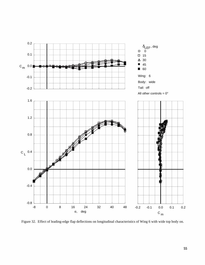
55
Figure 32. Effect of leading-edge flap deflections on longitudinal characteristics of Wing 6 with wide top body on.
, deg
01530
45
δLEF
Wing: 6
Body: wide
Tail: off
All other controls = 0°
60
484032241680-8-0.8
-0.4
0.0
0.4
0.8
1.2
1.6
LC
α, deg
-0.2
-0.1
0.0
0.1
0.2
Cm
0.20.10.0-0.1-0.2
C m

56
Figure 33. Effect of leading-edge flap deflections on longitudinal characteristics of Wing 7 with wide top body on.
, deg
01530
45
δLEF
Wing: 7
Body: wide
Tail: off
All other controls = 0°
60
484032241680-8-0.8
-0.4
0.0
0.4
0.8
1.2
1.6
LC
α, deg
-0.2
-0.1
0.0
0.1
0.2
Cm
0.20.10.0-0.1-0.2
C m
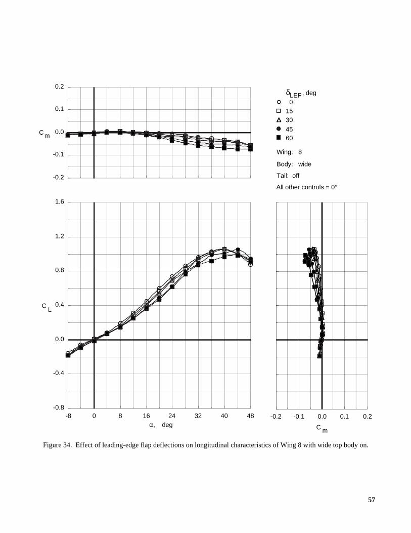
57
Figure 34. Effect of leading-edge flap deflections on longitudinal characteristics of Wing 8 with wide top body on.
, deg
01530
45
δLEF
Wing: 8
Body: wide
Tail: off
All other controls = 0°
60
484032241680-8-0.8
-0.4
0.0
0.4
0.8
1.2
1.6
LC
α, deg
-0.2
-0.1
0.0
0.1
0.2
Cm
0.20.10.0-0.1-0.2
C m

58
Figure 35. Effect of vertical tail size on longitudinal characteristics of Wing 5 with narrow top body on and leading-edge flaps deflected.
Vertical tail
OffSmall
Medium
Wing: 5
δLEF = 45°
Body: narrow
All other controls = 0°
484032241680-8-0.8
-0.4
0.0
0.4
0.8
1.2
1.6
LC
α, deg
-0.2
-0.1
0.0
0.1
0.2
Cm
0.20.10.0-0.1-0.2
C m

59
Figure 36. Effect of vertical tail size on longitudinal characteristics of Wing 6 with narrow top body on and leading-edge flaps deflected.
Vertical tail
OffSmall
Medium
Wing: 6
δLEF = 45°
Body: narrow
All other controls = 0°
484032241680-8-0.8
-0.4
0.0
0.4
0.8
1.2
1.6
LC
α, deg
-0.2
-0.1
0.0
0.1
0.2
Cm
0.20.10.0-0.1-0.2
C m
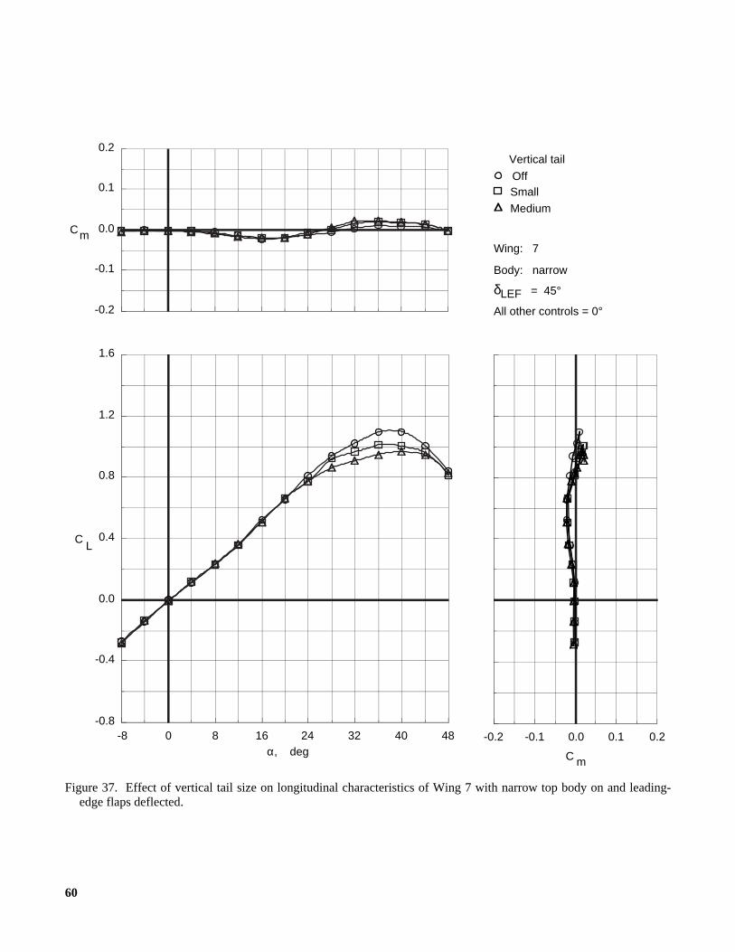
60
Figure 37. Effect of vertical tail size on longitudinal characteristics of Wing 7 with narrow top body on and leading-edge flaps deflected.
Vertical tail
OffSmall
Medium
Wing: 7
δLEF = 45°
Body: narrow
All other controls = 0°
484032241680-8-0.8
-0.4
0.0
0.4
0.8
1.2
1.6
LC
α, deg
-0.2
-0.1
0.0
0.1
0.2
Cm
0.20.10.0-0.1-0.2
C m

61
Figure 38. Effect of vertical tail size on longitudinal characteristics of Wing 8 with narrow top body on and leading-edge flaps deflected.
Vertical tail
OffSmall
Medium
Wing: 8
δLEF = 45°
Body: narrow
All other controls = 0°
484032241680-8-0.8
-0.4
0.0
0.4
0.8
1.2
1.6
LC
α, deg
-0.2
-0.1
0.0
0.1
0.2
Cm
0.20.10.0-0.1-0.2
C m

62
Figure 39. Control effectiveness of symmetric deflections of inboard trailing-edge flaps on Wing 5 with wide top bodyon and leading-edge flaps deflected.
δf,IB, deg
All other controls = 0°
Wing: 5
= 45°Body: wide
Tail: off
δLEF
0-30-15
1530
484032241680-8-0.8
-0.4
0.0
0.4
0.8
1.2
1.6
LC
α, deg
-0.2
-0.1
0.0
0.1
0.2
Cm
0.20.10.0-0.1-0.2
C m
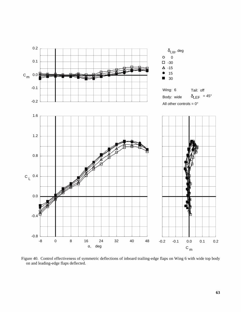
63
Figure 40. Control effectiveness of symmetric deflections of inboard trailing-edge flaps on Wing 6 with wide top bodyon and leading-edge flaps deflected.
All other controls = 0°
Wing: 6
= 45°Body: wide
Tail: off
δLEF
0-30-15
1530
484032241680-8-0.8
-0.4
0.0
0.4
0.8
1.2
1.6
LC
α, deg
-0.2
-0.1
0.0
0.1
0.2
Cm
0.20.10.0-0.1-0.2
C m
δf,IB, deg
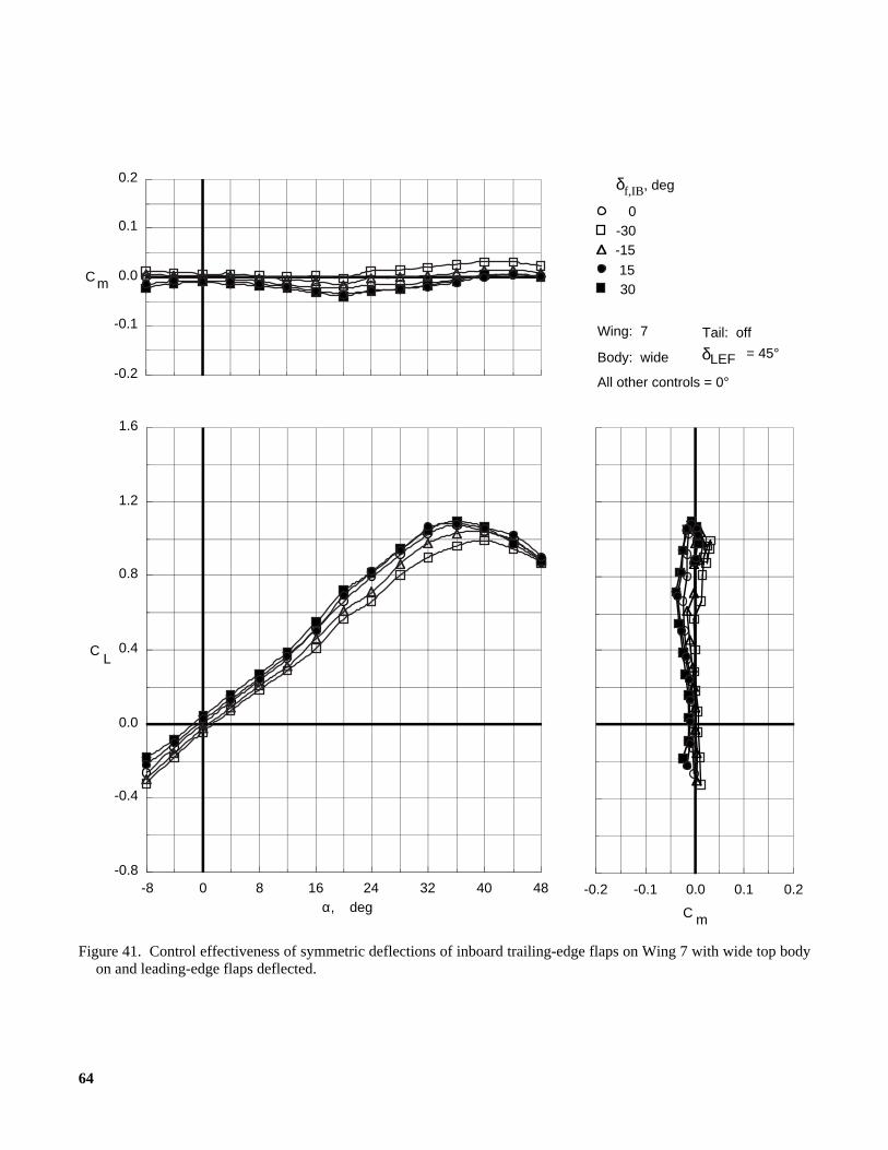
64
Figure 41. Control effectiveness of symmetric deflections of inboard trailing-edge flaps on Wing 7 with wide top bodyon and leading-edge flaps deflected.
All other controls = 0°
Wing: 7
= 45°Body: wide
Tail: off
δLEF
0-30-15
1530
484032241680-8-0.8
-0.4
0.0
0.4
0.8
1.2
1.6
LC
α, deg
-0.2
-0.1
0.0
0.1
0.2
Cm
0.20.10.0-0.1-0.2
C m
δf,IB, deg

65
Figure 42. Control effectiveness of symmetric deflections of inboard trailing-edge flaps on Wing 8 with wide top bodyon and leading-edge flaps deflected.
All other controls = 0°
Wing: 8
= 45°Body: wide
Tail: off
δLEF
0-30-15
1530
484032241680-8-0.8
-0.4
0.0
0.4
0.8
1.2
1.6
LC
α, deg
-0.2
-0.1
0.0
0.1
0.2
Cm
0.20.10.0-0.1-0.2
C m
δf,IB, deg

66
Figure 43. Control effectiveness of symmetric deflections of middle trailing-edge flaps on Wing 5 with wide top bodyon and leading-edge flaps deflected.
0-30-15
1530
All other controls = 0°
Wing: 5
= 45°Body: wide
Tail: off
δLEF
484032241680-8-0.8
-0.4
0.0
0.4
0.8
1.2
1.6
LC
α, deg
-0.2
-0.1
0.0
0.1
0.2
Cm
0.20.10.0-0.1-0.2
C m
δf,MID, deg

67
Figure 44. Control effectiveness of symmetric deflections of middle trailing-edge flaps on Wing 6 with wide top bodyon and leading-edge flaps deflected.
0-30-15
1530
All other controls = 0°
Wing: 6
= 45°Body: wide
Tail: off
δLEF
484032241680-8-0.8
-0.4
0.0
0.4
0.8
1.2
1.6
LC
α, deg
-0.2
-0.1
0.0
0.1
0.2
Cm
0.20.10.0-0.1-0.2
C m
δf,MID, deg

68
Figure 45. Control effectiveness of symmetric deflections of middle trailing-edge flaps on Wing 7 with wide top bodyon and leading-edge flaps deflected.
0-30-15
1530
All other controls = 0°
Wing: 7
= 45°Body: wide
Tail: off
δLEF
484032241680-8-0.8
-0.4
0.0
0.4
0.8
1.2
1.6
LC
α, deg
-0.2
-0.1
0.0
0.1
0.2
Cm
0.20.10.0-0.1-0.2
C m
δf,MID, deg
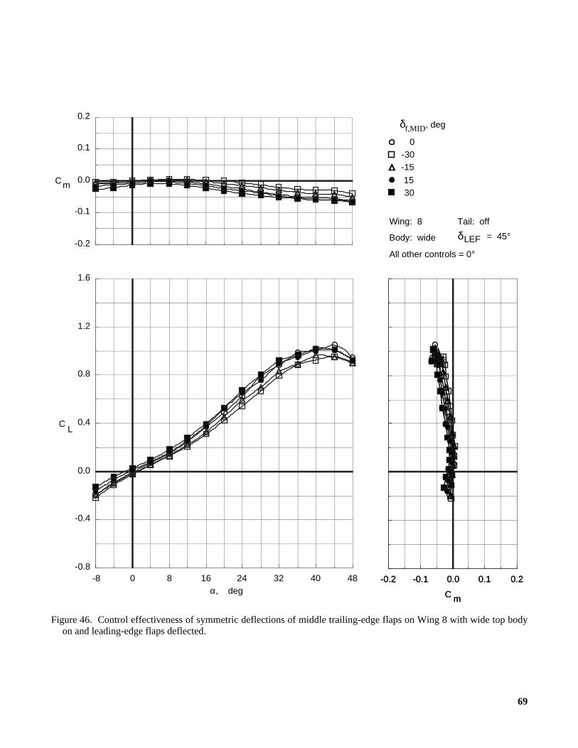
69
Figure 46. Control effectiveness of symmetric deflections of middle trailing-edge flaps on Wing 8 with wide top bodyon and leading-edge flaps deflected.
0-30-15
1530
All other controls = 0°
Wing: 8
= 45°Body: wide
Tail: off
δLEF
484032241680-8-0.8
-0.4
0.0
0.4
0.8
1.2
1.6
LC
α, deg
-0.2
-0.1
0.0
0.1
0.2
Cm
0.20.10.0-0.1-0.2
C m
0.20.10.0-0.1-0.2
C m
δf,MID, deg
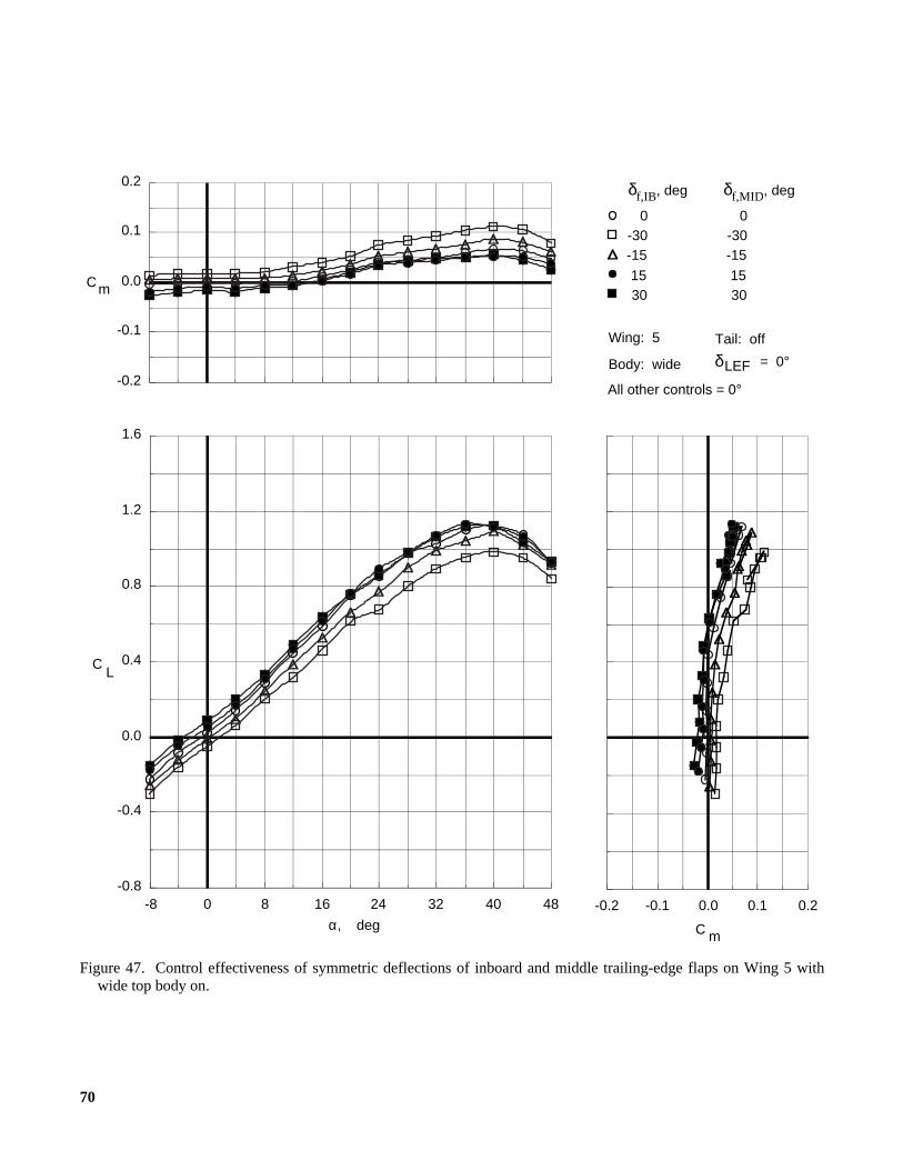
70
Figure 47. Control effectiveness of symmetric deflections of inboard and middle trailing-edge flaps on Wing 5 withwide top body on.
All other controls = 0°
Wing: 5
= 0°Body: wide
Tail: off
δLEF
0-30-15
1530
0-30-15
1530
484032241680-8-0.8
-0.4
0.0
0.4
0.8
1.2
1.6
LC
α, deg
-0.2
-0.1
0.0
0.1
0.2
Cm
0.20.10.0-0.1-0.2
C m
δf,IB, deg δf,MID, deg
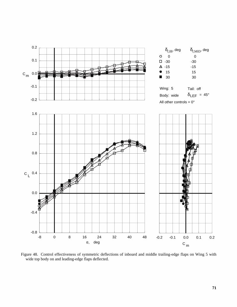
71
Figure 48. Control effectiveness of symmetric deflections of inboard and middle trailing-edge flaps on Wing 5 withwide top body on and leading-edge flaps deflected.
All other controls = 0°
Wing: 5
= 45°Body: wide
Tail: off
δLEF
0-30-15
1530
0-30-15
1530
484032241680-8-0.8
-0.4
0.0
0.4
0.8
1.2
1.6
LC
α, deg
-0.2
-0.1
0.0
0.1
0.2
Cm
0.20.10.0-0.1-0.2
C m
δf,IB, deg δf,MID, deg

72
Figure 49. Control effectiveness of symmetric deflections of inboard and middle trailing-edge flaps on Wing 6 withwide top body on and leading-edge flaps deflected.
All other controls = 0°
Wing: 6
= 45°Body: wide
Tail: off
δLEF
0-30-15
1530
0-30-15
1530
484032241680-8-0.8
-0.4
0.0
0.4
0.8
1.2
1.6
LC
α, deg
-0.2
-0.1
0.0
0.1
0.2
Cm
0.20.10.0-0.1-0.2
C m
δf,IB, deg δf,MID, deg
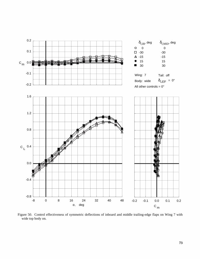
73
Figure 50. Control effectiveness of symmetric deflections of inboard and middle trailing-edge flaps on Wing 7 withwide top body on.
All other controls = 0°
Wing: 7
= 0°Body: wide
Tail: off
δLEF
0-30-15
1530
0-30-15
1530
484032241680-8-0.8
-0.4
0.0
0.4
0.8
1.2
1.6
LC
α, deg
-0.2
-0.1
0.0
0.1
0.2
Cm
0.20.10.0-0.1-0.2
C m
δf,IB, deg δf,MID, deg

74
Figure 51. Control effectiveness of symmetric deflections of inboard and middle trailing-edge flaps on Wing 7 withwide top body on and leading-edge flaps deflected.
All other controls = 0°
Wing: 7
= 45°Body: wide
Tail: off
δLEF
0-30-15
1530
0-30-15
1530
484032241680-8-0.8
-0.4
0.0
0.4
0.8
1.2
1.6
LC
α, deg
-0.2
-0.1
0.0
0.1
0.2
Cm
0.20.10.0-0.1-0.2
C m
δf,IB, deg δf,MID, deg
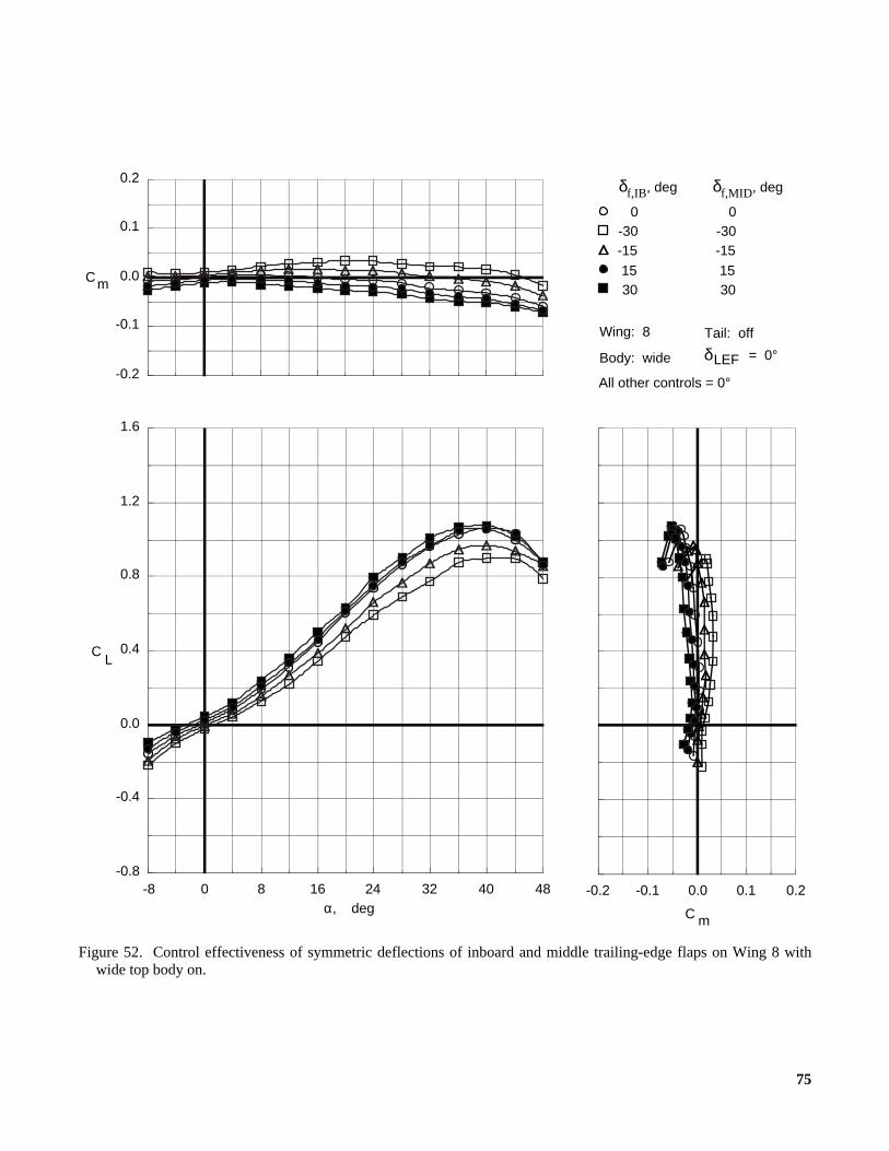
75
Figure 52. Control effectiveness of symmetric deflections of inboard and middle trailing-edge flaps on Wing 8 withwide top body on.
All other controls = 0°
Wing: 8
= 0°Body: wide
Tail: off
δLEF
0-30-15
1530
0-30-15
1530
484032241680-8-0.8
-0.4
0.0
0.4
0.8
1.2
1.6
LC
α, deg
-0.2
-0.1
0.0
0.1
0.2
Cm
0.20.10.0-0.1-0.2
C m
δf,IB, deg δf,MID, deg
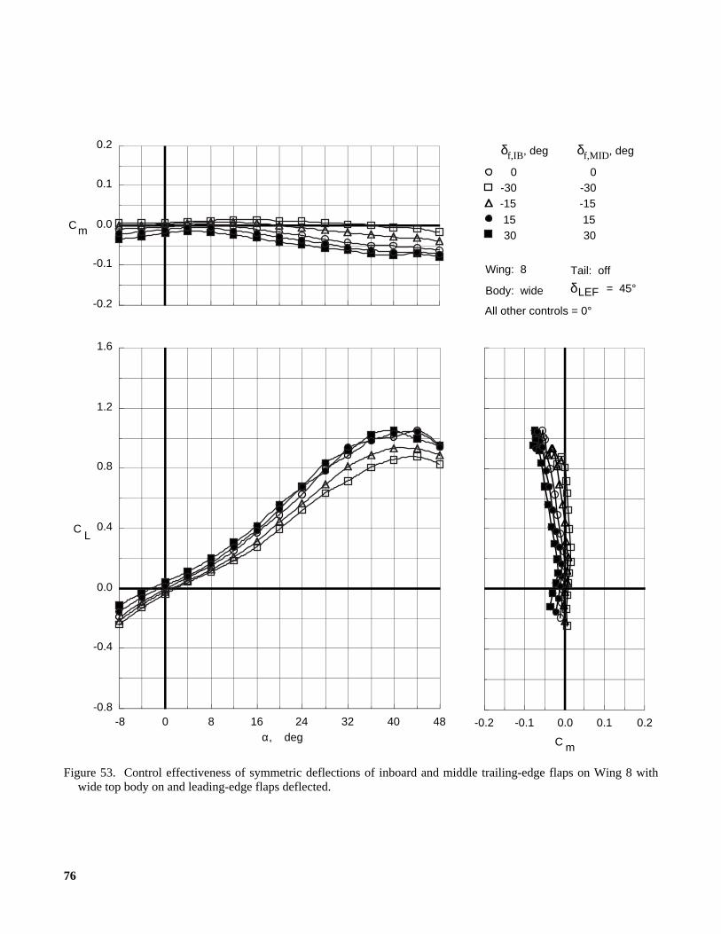
76
Figure 53. Control effectiveness of symmetric deflections of inboard and middle trailing-edge flaps on Wing 8 withwide top body on and leading-edge flaps deflected.
All other controls = 0°
Wing: 8
= 45°Body: wide
Tail: off
δLEF
0-30-15
1530
0-30-15
1530
484032241680-8-0.8
-0.4
0.0
0.4
0.8
1.2
1.6
LC
α, deg
-0.2
-0.1
0.0
0.1
0.2
Cm
0.20.10.0-0.1-0.2
C m
δf,IB, deg δf,MID, deg

77
Figure 54. Control effectiveness of symmetric deflections of trailing-edge flaps and body flaps on Wing 5 with wide topbody on and leading-edge flaps deflected.
All other controls = 0°
Wing: 5 δLEF = 45°
Body: wide Tail: off
0303030
0 0 0 0 0 0
303030 0
5873
30 30 30 73
484032241680-8-0.8
-0.4
0.0
0.4
0.8
1.2
1.6
LC
α, deg
-0.2
-0.1
0.0
0.1
0.2
Cm
0.20.10.0-0.1-0.2
C m
δf,IB,
deg
δf,MID,
deg
δf,OB,
deg
δbf,
deg
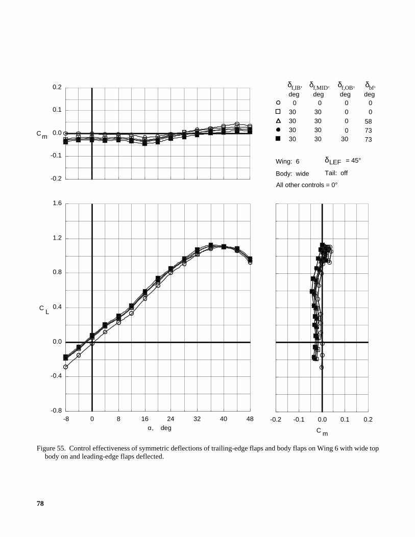
78
Figure 55. Control effectiveness of symmetric deflections of trailing-edge flaps and body flaps on Wing 6 with wide topbody on and leading-edge flaps deflected.
All other controls = 0°
Wing: 6 δLEF = 45°
Body: wide Tail: off
0303030
0 0 0 0 0 0
303030 0
5873
30 30 30 73
484032241680-8-0.8
-0.4
0.0
0.4
0.8
1.2
1.6
LC
α, deg
-0.2
-0.1
0.0
0.1
0.2
Cm
0.20.10.0-0.1-0.2
C m
δf,IB,
deg
δf,MID,
deg
δf,OB,
deg
δbf,
deg
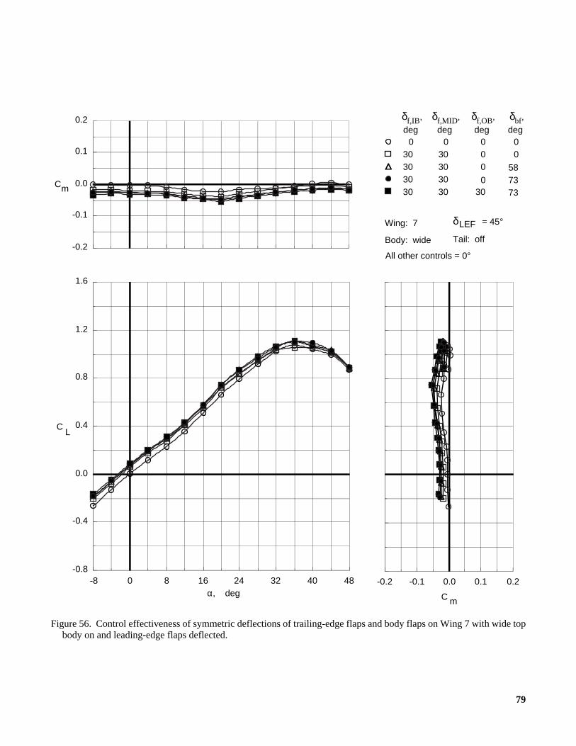
79
Figure 56. Control effectiveness of symmetric deflections of trailing-edge flaps and body flaps on Wing 7 with wide topbody on and leading-edge flaps deflected.
All other controls = 0°
Wing: 7 δLEF = 45°
Body: wide Tail: off
0303030
0 0 0 0 0 0
303030 0
5873
30 30 30 73
484032241680-8-0.8
-0.4
0.0
0.4
0.8
1.2
1.6
LC
α, deg
-0.2
-0.1
0.0
0.1
0.2
Cm
0.20.10.0-0.1-0.2
C m
δf,IB,
deg
δf,MID,
deg
δf,OB,
deg
δbf,
deg

80
Figure 57. Control effectiveness of symmetric deflections of trailing-edge flaps and body flaps on Wing 8 with wide topbody on and leading-edge flaps deflected.
All other controls = 0°
Wing: 8 δLEF = 45°
Body: wide Tail: off
0303030
0 0 0 0 0 0
303030 0
5873
30 30 30 73
484032241680-8-0.8
-0.4
0.0
0.4
0.8
1.2
1.6
LC
α, deg
-0.2
-0.1
0.0
0.1
0.2
Cm
0.20.10.0-0.1-0.2
C m
δf,IB,
deg
δf,MID,
deg
δf,OB,
deg
δbf,
deg
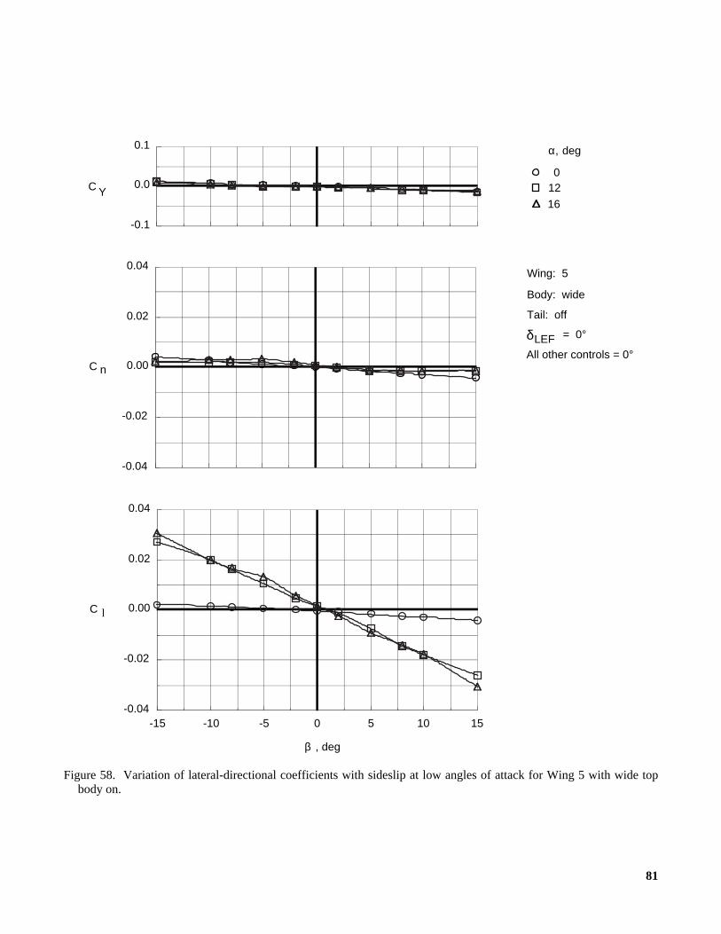
81
Figure 58. Variation of lateral-directional coefficients with sideslip at low angles of attack for Wing 5 with wide topbody on.
α, deg
012
16
Wing: 5
δLEF = 0°
Body: wide
Tail: off
All other controls = 0°
-0.04
-0.02
0.00
0.02
0.04
C n
-0.1
0.0
0.1
C Y
C l
151050-5-10-15-0.04
-0.02
0.00
0.02
0.04
, degβ
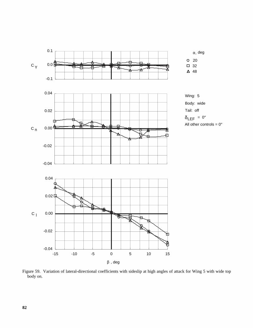
82
Figure 59. Variation of lateral-directional coefficients with sideslip at high angles of attack for Wing 5 with wide topbody on.
α, deg
203248
Wing: 5
δLEF = 0°
Body: wide
Tail: off
All other controls = 0°
C l
151050-5-10-15-0.04
-0.02
0.00
0.02
0.04
, degβ
-0.04
-0.02
0.00
0.02
0.04
C n
-0.1
0.0
0.1
C Y
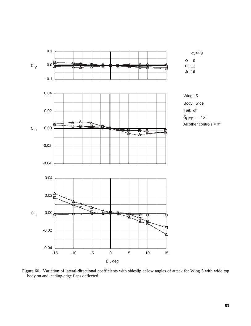
83
Figure 60. Variation of lateral-directional coefficients with sideslip at low angles of attack for Wing 5 with wide topbody on and leading-edge flaps deflected.
α, deg
012
16
Wing: 5
δLEF = 45°
Body: wide
Tail: off
All other controls = 0°
C l
151050-5-10-15-0.04
-0.02
0.00
0.02
0.04
, degβ
-0.04
-0.02
0.00
0.02
0.04
C n
-0.1
0.0
0.1
C Y

84
Figure 61. Variation of lateral-directional coefficients with sideslip at high angles of attack for Wing 5 with wide topbody on and leading-edge flaps deflected.
α, deg
203248
Wing: 5
δLEF = 45°
Body: wide
Tail: off
All other controls = 0°
C l
151050-5-10-15-0.04
-0.02
0.00
0.02
0.04
, degβ
-0.04
-0.02
0.00
0.02
0.04
C n
-0.1
0.0
0.1
C Y

85
Figure 62. Variation of lateral-directional coefficients with sideslip at low angles of attack for Wing 6 with wide topbody on.
α, deg
012
16
Wing: 6
δLEF = 0°
Body: wide
Tail: off
All other controls = 0°
C l
151050-5-10-15-0.04
-0.02
0.00
0.02
0.04
, degβ
-0.04
-0.02
0.00
0.02
0.04
C n
-0.1
0.0
0.1
C Y
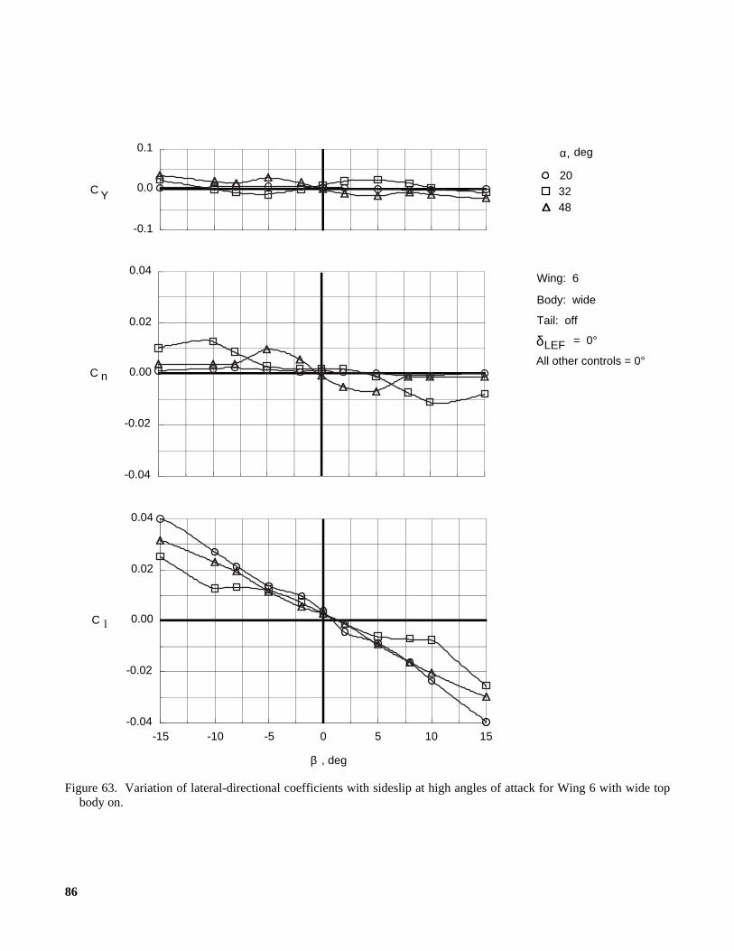
86
Figure 63. Variation of lateral-directional coefficients with sideslip at high angles of attack for Wing 6 with wide topbody on.
α, deg
203248
Wing: 6
δLEF = 0°
Body: wide
Tail: off
All other controls = 0°
C l
151050-5-10-15-0.04
-0.02
0.00
0.02
0.04
, degβ
-0.04
-0.02
0.00
0.02
0.04
C n
-0.1
0.0
0.1
C Y
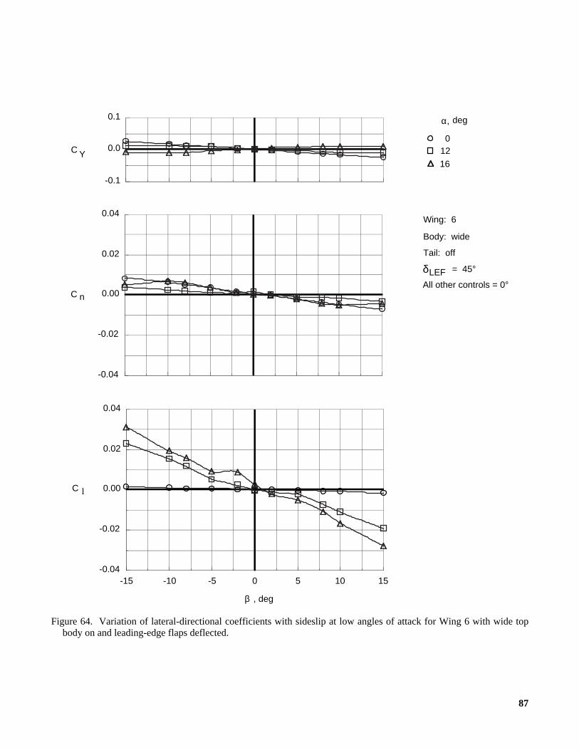
87
Figure 64. Variation of lateral-directional coefficients with sideslip at low angles of attack for Wing 6 with wide topbody on and leading-edge flaps deflected.
α, deg
012
16
Wing: 6
δLEF = 45°
Body: wide
Tail: off
All other controls = 0°
C l
151050-5-10-15-0.04
-0.02
0.00
0.02
0.04
, degβ
-0.04
-0.02
0.00
0.02
0.04
C n
-0.1
0.0
0.1
C Y
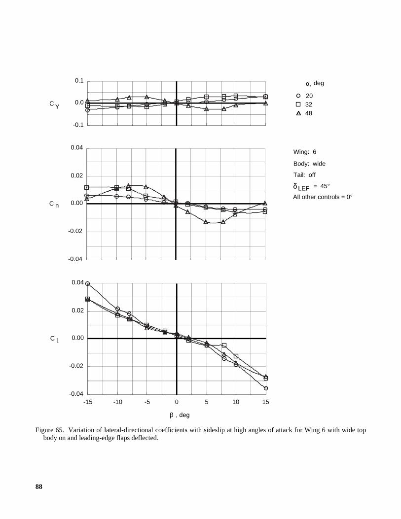
88
Figure 65. Variation of lateral-directional coefficients with sideslip at high angles of attack for Wing 6 with wide topbody on and leading-edge flaps deflected.
α, deg
203248
Wing: 6
δ LEF = 45°
Body: wide
Tail: off
All other controls = 0°
C l
151050-5-10-15-0.04
-0.02
0.00
0.02
0.04
, degβ
-0.04
-0.02
0.00
0.02
0.04
C n
-0.1
0.0
0.1
C Y

89
Figure 66. Variation of lateral-directional coefficients with sideslip at low angles of attack for Wing 7 with wide topbody on.
α, deg
012
16
Wing: 7
δLEF = 0°
Body: wide
Tail: off
All other controls = 0°
C l
151050-5-10-15-0.04
-0.02
0.00
0.02
0.04
, degβ
-0.04
-0.02
0.00
0.02
0.04
C n
-0.1
0.0
0.1
C Y

90
Figure 67. Variation of lateral-directional coefficients with sideslip at high angles of attack for Wing 7 with wide topbody on.
α, deg
203248
Wing: 7
δLEF = 0°
Body: wide
Tail: off
All other controls = 0°
C l
151050-5-10-15-0.06
-0.04
-0.02
0.00
0.02
0.04
0.06
, degβ
-0.04
-0.02
0.00
0.02
0.04
C n
-0.1
0.0
0.1
C Y

91
Figure 68. Variation of lateral-directional coefficients with sideslip at low angles of attack for Wing 7 with wide topbody on and leading-edge flaps deflected.
α, deg
012
16
Wing: 7
δLEF = 45°
Body: wide
Tail: off
All other controls = 0°
C l
151050-5-10-15-0.04
-0.02
0.00
0.02
0.04
, degβ
-0.04
-0.02
0.00
0.02
0.04
C n
-0.1
0.0
0.1
C Y
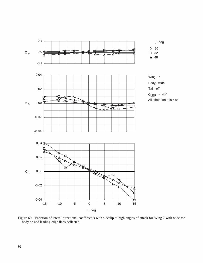
92
Figure 69. Variation of lateral-directional coefficients with sideslip at high angles of attack for Wing 7 with wide topbody on and leading-edge flaps deflected.
α, deg
203248
Wing: 7
δLEF = 45°
Body: wide
Tail: off
All other controls = 0°
C l
151050-5-10-15-0.04
-0.02
0.00
0.02
0.04
, degβ
-0.04
-0.02
0.00
0.02
0.04
C n
-0.1
0.0
0.1
C Y
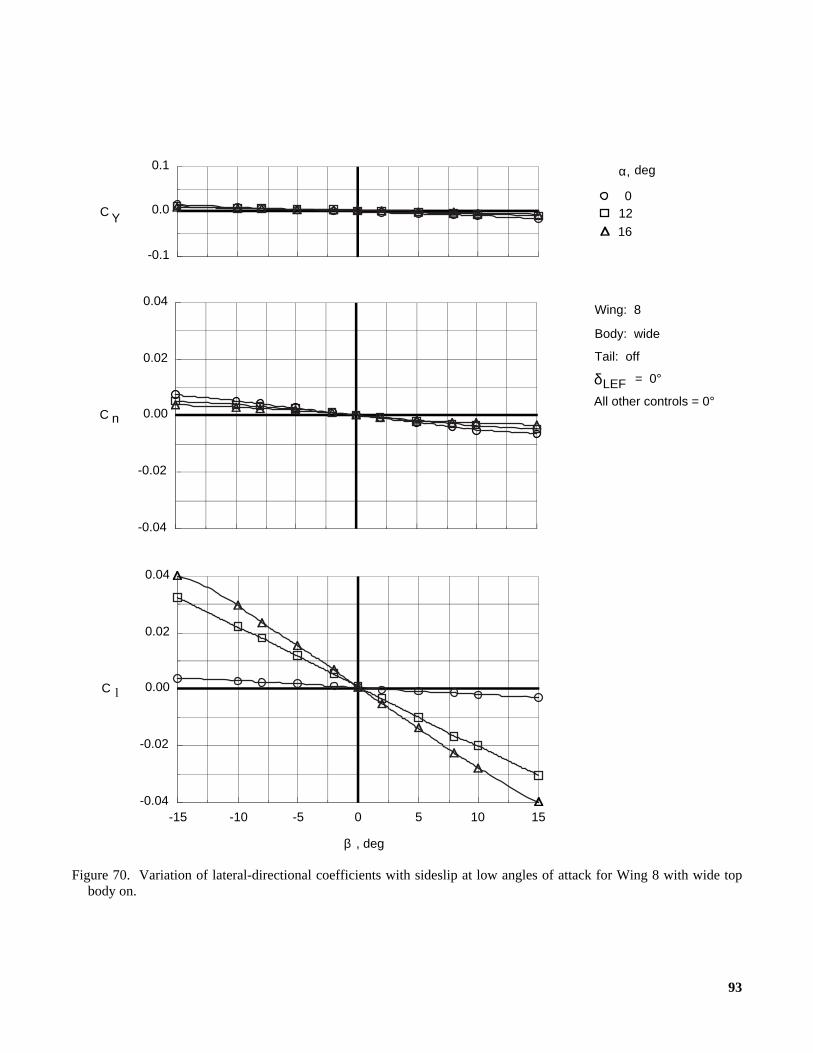
93
Figure 70. Variation of lateral-directional coefficients with sideslip at low angles of attack for Wing 8 with wide topbody on.
α, deg
012
16
Wing: 8
δLEF = 0°
Body: wide
Tail: off
All other controls = 0°
-0.04
-0.02
0.00
0.02
0.04
C n
-0.1
0.0
0.1
C Y
C l
151050-5-10-15-0.04
-0.02
0.00
0.02
0.04
, degβ
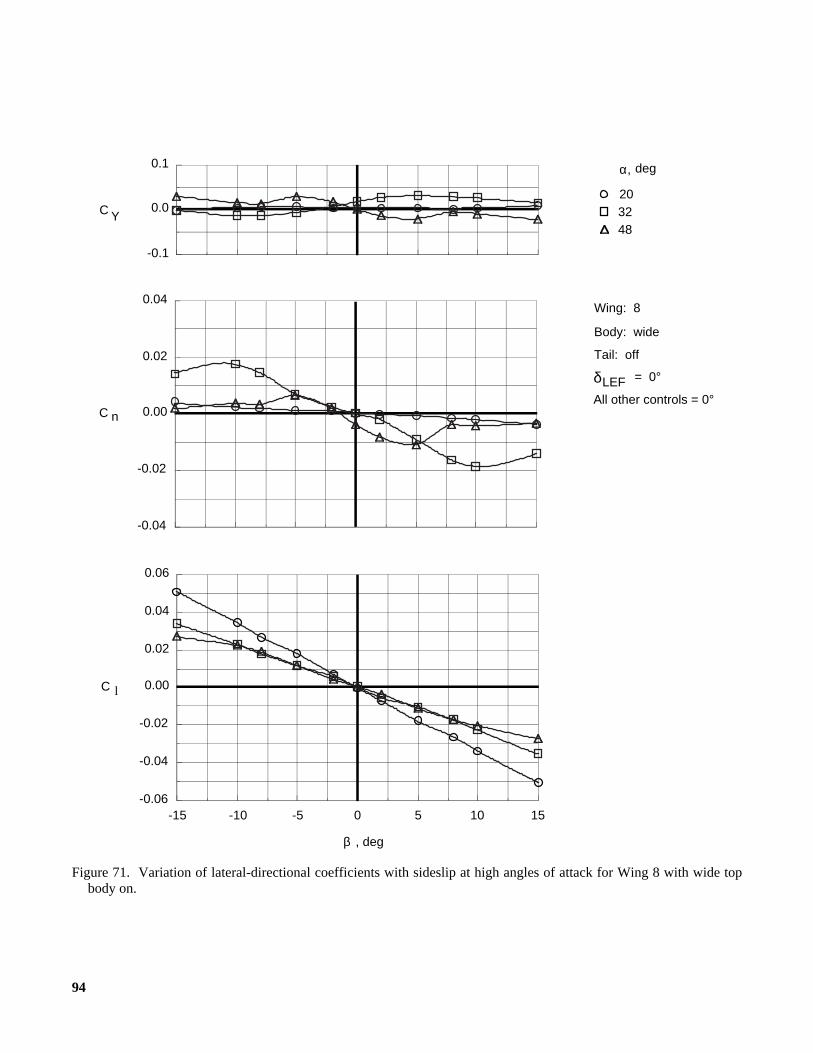
94
Figure 71. Variation of lateral-directional coefficients with sideslip at high angles of attack for Wing 8 with wide topbody on.
α, deg
203248
Wing: 8
δLEF = 0°
Body: wide
Tail: off
All other controls = 0°
C l
151050-5-10-15-0.06
-0.04
-0.02
0.00
0.02
0.04
0.06
, degβ
-0.04
-0.02
0.00
0.02
0.04
C n
-0.1
0.0
0.1
C Y
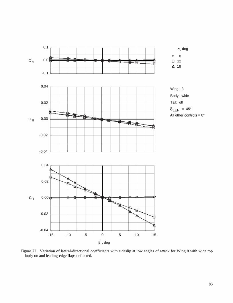
95
Figure 72. Variation of lateral-directional coefficients with sideslip at low angles of attack for Wing 8 with wide topbody on and leading-edge flaps deflected.
α, deg
012
16
Wing: 8
δLEF = 45°
Body: wide
Tail: off
All other controls = 0°
C l
151050-5-10-15-0.04
-0.02
0.00
0.02
0.04
, degβ
-0.04
-0.02
0.00
0.02
0.04
C n
-0.1
0.0
0.1
C Y

96
Figure 73. Variation of lateral-directional coefficients with sideslip at high angles of attack for Wing 8 with wide topbody on and leading-edge flaps deflected.
α, deg
203248
Wing: 8
δLEF = 45°
Body: wide
Tail: off
All other controls = 0°
C l
151050-5-10-15-0.06
-0.04
-0.02
0.00
0.02
0.04
0.06
, degβ
-0.04
-0.02
0.00
0.02
0.04
C n
-0.1
0.0
0.1
C Y

97
Figure 74. Lateral-directional stability characteristics of wing planforms with top body off.
Stable
Unstable
Unstable
Stable
Wing
5 6 7
8
δLEF = 0°
Body: off
Tail: off
All other controls = 0°
-0.004
-0.002
0.000
0.002
0.004
C n β
C l β
484032241680-8-0.005
-0.003
-0.001
0.001
0.003
α, deg
-0.01
0.00
0.01
C Yβ
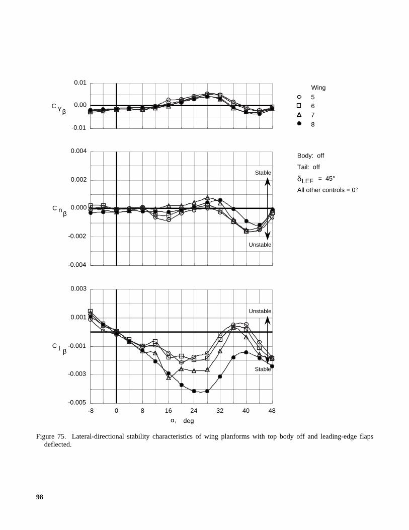
98
Figure 75. Lateral-directional stability characteristics of wing planforms with top body off and leading-edge flapsdeflected.
Stable
Unstable
Unstable
Stable
Wing
5 6 7
8
δLEF = 45°
Body: off
Tail: off
All other controls = 0°
-0.004
-0.002
0.000
0.002
0.004
C n β
C l β
484032241680-8-0.005
-0.003
-0.001
0.001
0.003
α, deg
-0.01
0.00
0.01
C Yβ
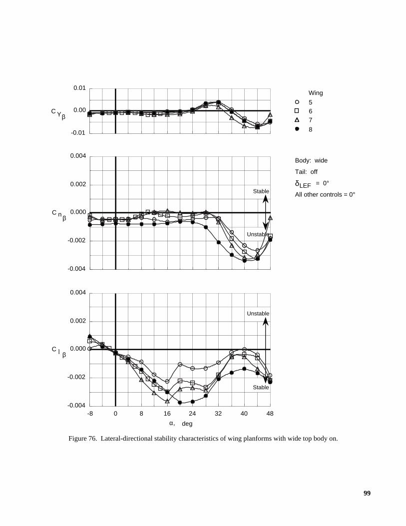
99
Figure 76. Lateral-directional stability characteristics of wing planforms with wide top body on.
Stable
Unstable
Unstable
Stable
Wing
5 6 7
8
δLEF = 0°
Body: wide
Tail: off
All other controls = 0°
-0.004
-0.002
0.000
0.002
0.004
C n β
C l β
484032241680-8-0.004
-0.002
0.000
0.002
0.004
α, deg
-0.01
0.00
0.01
C Yβ
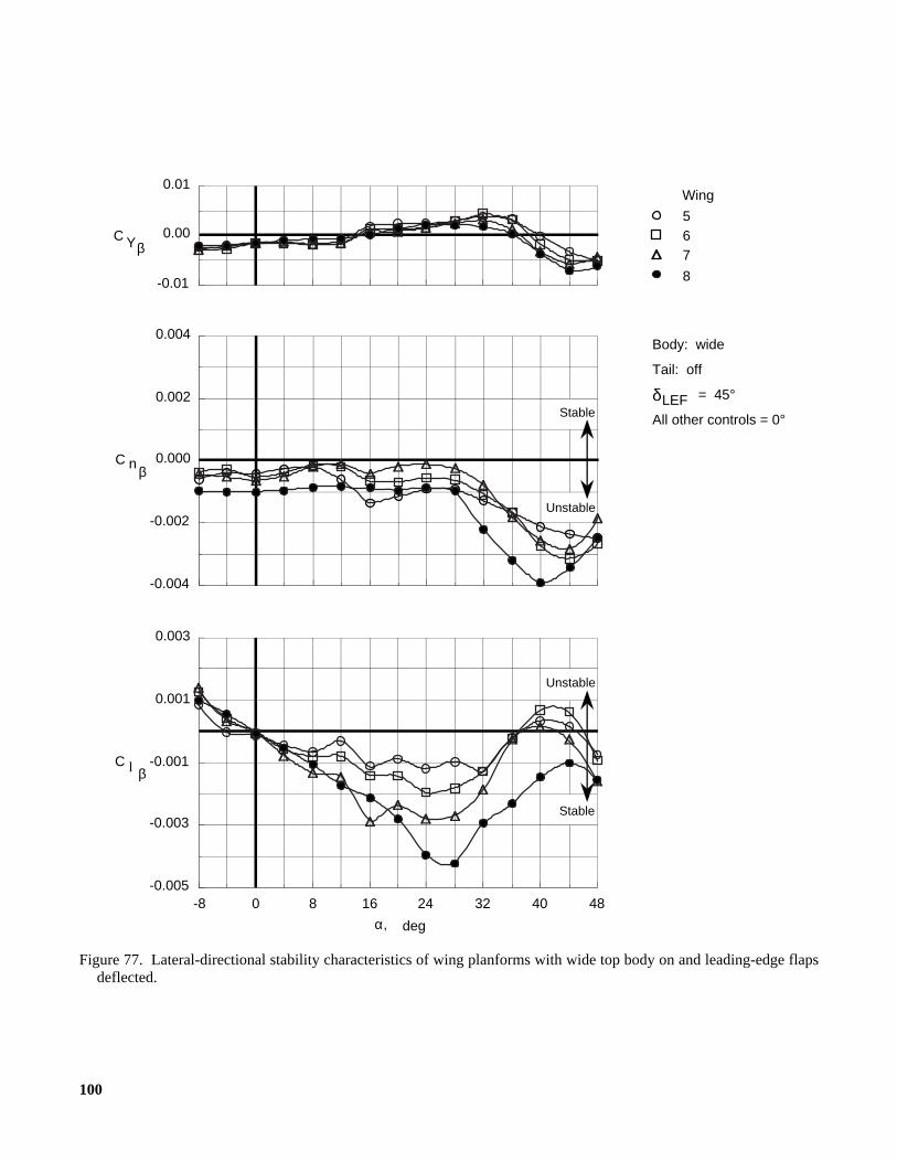
100
Figure 77. Lateral-directional stability characteristics of wing planforms with wide top body on and leading-edge flapsdeflected.
Stable
Unstable
Unstable
Stable
Wing
5 6 7
8
δLEF = 45°
Body: wide
Tail: off
All other controls = 0°
-0.004
-0.002
0.000
0.002
0.004
C n β
C l β
484032241680-8-0.005
-0.003
-0.001
0.001
0.003
α, deg
-0.01
0.00
0.01
C Yβ
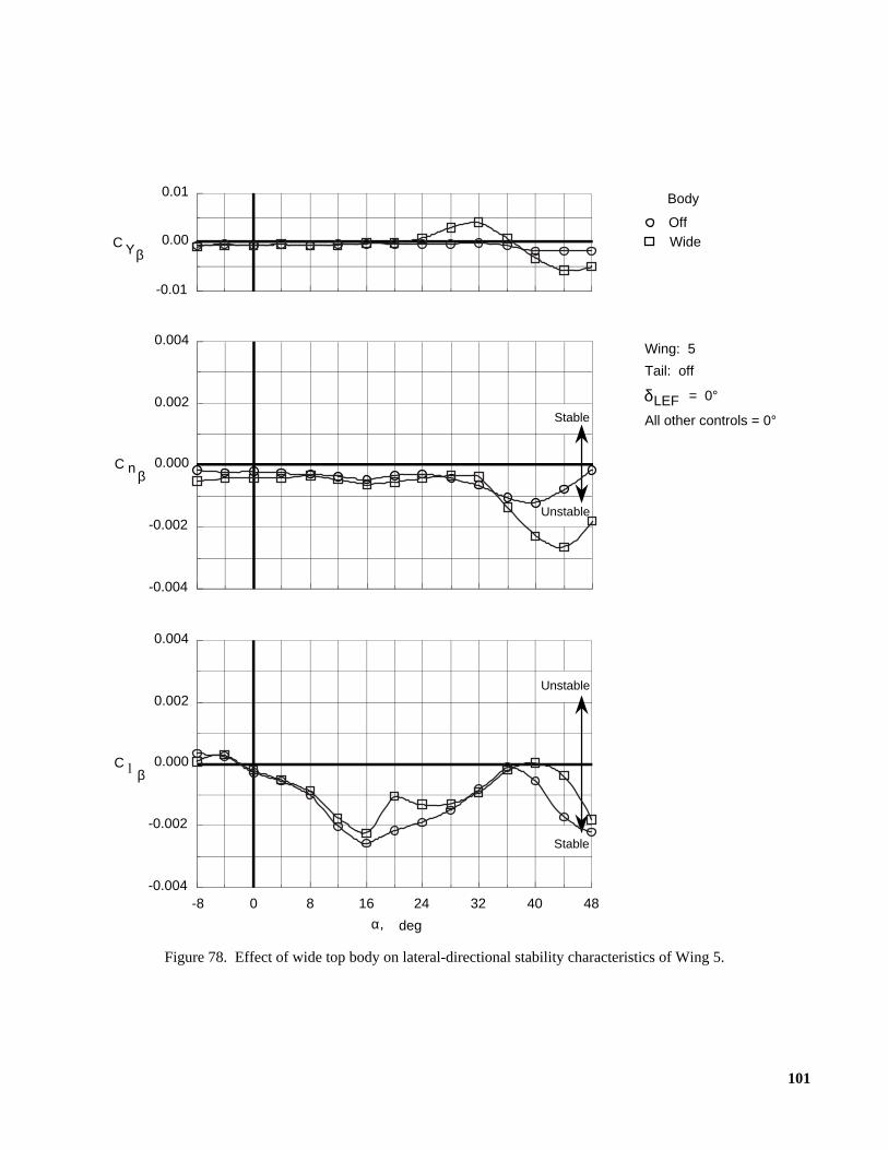
101
Figure 78. Effect of wide top body on lateral-directional stability characteristics of Wing 5.
OffWide
Body
Wing: 5
δLEF = 0°
Tail: off
All other controls = 0°
Stable
Unstable
Unstable
Stable
-0.004
-0.002
0.000
0.002
0.004
C n β
C l β
484032241680-8-0.004
-0.002
0.000
0.002
0.004
α, deg
-0.01
0.00
0.01
C Yβ
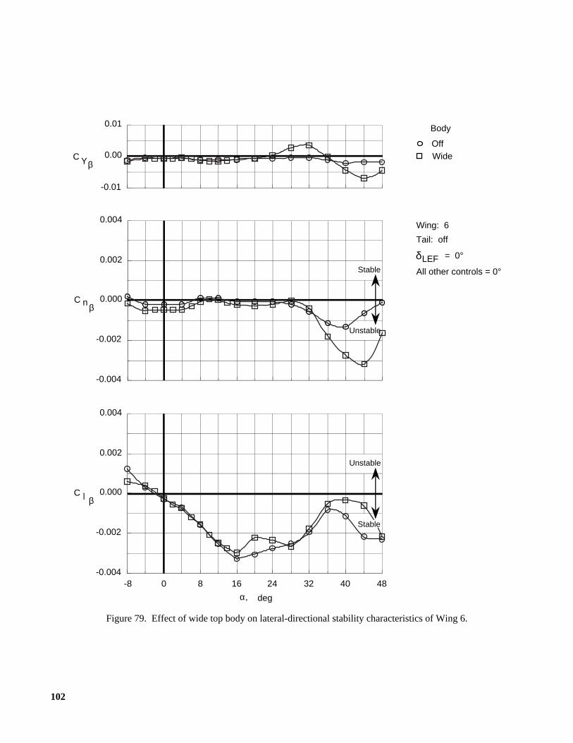
102
Figure 79. Effect of wide top body on lateral-directional stability characteristics of Wing 6.
OffWide
Body
Wing: 6
δLEF = 0°
Tail: off
All other controls = 0°
Unstable
Unstable
Stable
-0.004
-0.002
0.000
0.002
0.004
C n β
C l β
484032241680-8-0.004
-0.002
0.000
0.002
0.004
α, deg
-0.01
0.00
0.01
C Yβ
Stable
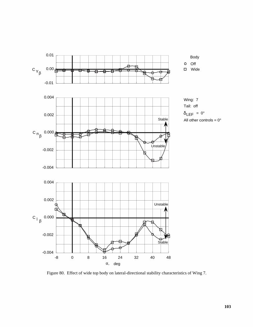
103
Figure 80. Effect of wide top body on lateral-directional stability characteristics of Wing 7.
OffWide
Body
Wing: 7
δLEF = 0°
Tail: off
All other controls = 0°
Stable
Unstable
Stable
-0.004
-0.002
0.000
0.002
0.004
C n β
C l β
484032241680-8-0.004
-0.002
0.000
0.002
0.004
α, deg
-0.01
0.00
0.01
C Yβ
Unstable
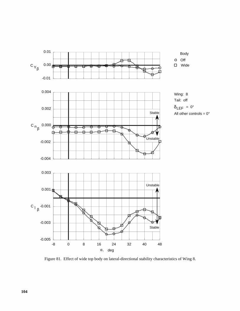
104
Figure 81. Effect of wide top body on lateral-directional stability characteristics of Wing 8.
OffWide
Body
Wing: 8
δLEF = 0°
Tail: off
All other controls = 0°
Stable
Unstable
Unstable
Stable
-0.004
-0.002
0.000
0.002
0.004
C n β
C l β
484032241680-8-0.005
-0.003
-0.001
0.001
0.003
α, deg
-0.01
0.00
0.01
C Yβ
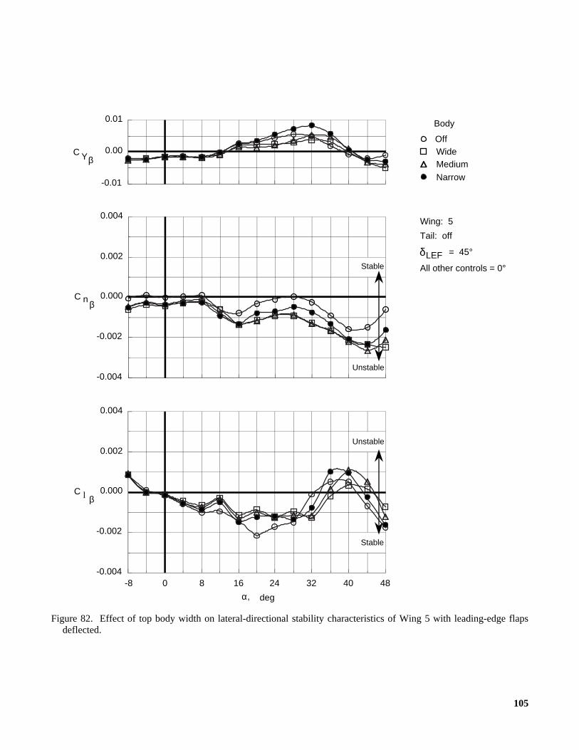
105
Figure 82. Effect of top body width on lateral-directional stability characteristics of Wing 5 with leading-edge flapsdeflected.
OffWideMedium
Narrow
Body
Wing: 5
δLEF = 45°
Tail: off
All other controls = 0°
Stable
Unstable
Unstable
Stable
-0.004
-0.002
0.000
0.002
0.004
C n β
C l β
484032241680-8-0.004
-0.002
0.000
0.002
0.004
α, deg
-0.01
0.00
0.01
C Yβ

106
Figure 83. Effect of top body width on lateral-directional stability characteristics of Wing 6 with leading-edge flapsdeflected.
OffWideMedium
Narrow
Body
Wing: 6
δLEF = 45°
Tail: off
All other controls = 0°
Stable
Unstable
Unstable
Stable
-0.004
-0.002
0.000
0.002
0.004
C n β
C l β
484032241680-8-0.004
-0.002
0.000
0.002
0.004
α, deg
-0.01
0.00
0.01
C Yβ

107
Figure 84. Effect of top body width on lateral-directional stability characteristics of Wing 7 with leading-edge flapsdeflected.
OffWideMedium
Narrow
Body
Wing: 7
δLEF = 45°
Tail: off
All other controls = 0°
Stable
Unstable
Unstable
Stable
-0.004
-0.002
0.000
0.002
0.004
C n β
C l β
484032241680-8-0.004
-0.002
0.000
0.002
0.004
α, deg
-0.01
0.00
0.01
C Y β
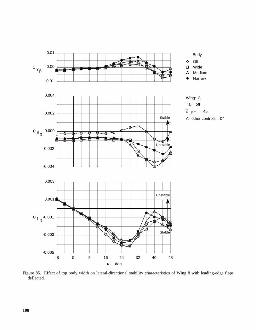
108
Figure 85. Effect of top body width on lateral-directional stability characteristics of Wing 8 with leading-edge flapsdeflected.
OffWideMedium
Narrow
Body
Wing: 8
δLEF = 45°
Tail: off
All other controls = 0°
Stable
Unstable
Unstable
Stable
-0.004
-0.002
0.000
0.002
0.004
C n β
C l β
484032241680-8-0.005
-0.003
-0.001
0.001
0.003
α, deg
-0.01
0.00
0.01
C Yβ
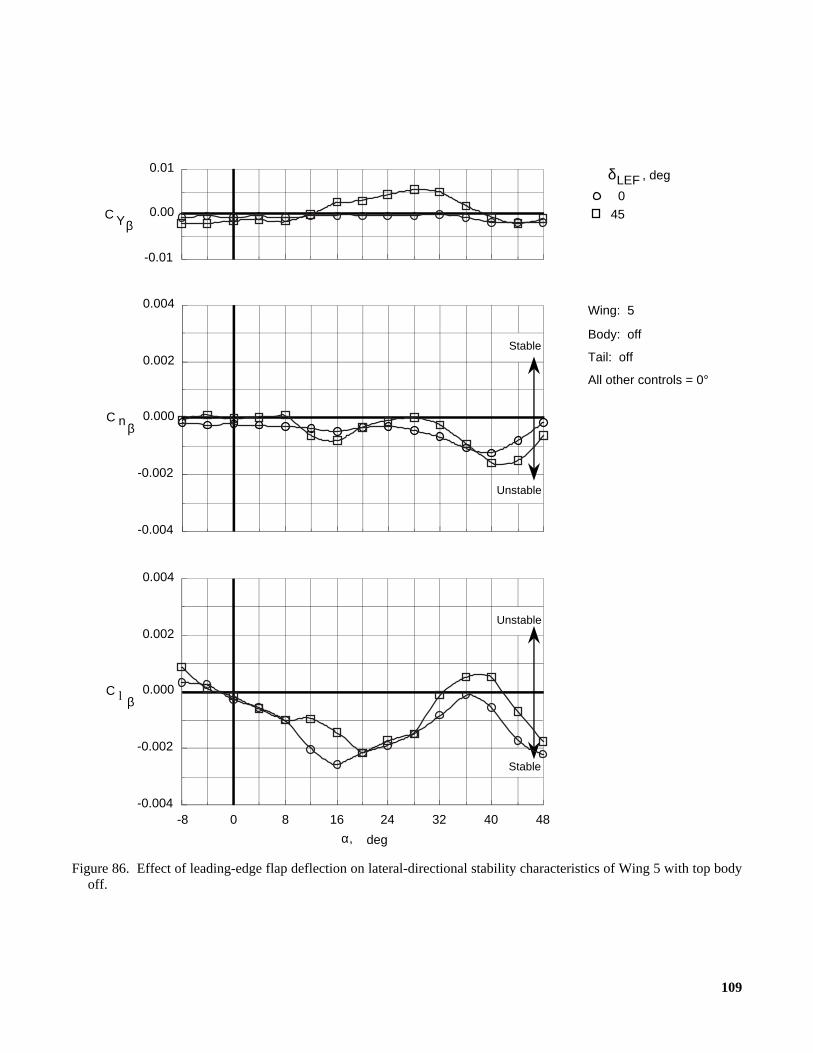
109
Figure 86. Effect of leading-edge flap deflection on lateral-directional stability characteristics of Wing 5 with top bodyoff.
Stable
Unstable
Unstable
Stable
Wing: 5
Body: off
Tail: off
All other controls = 0°
δLEF 0
45
, deg
-0.004
-0.002
0.000
0.002
0.004
C n β
C l β
484032241680-8-0.004
-0.002
0.000
0.002
0.004
α, deg
-0.01
0.00
0.01
C Yβ
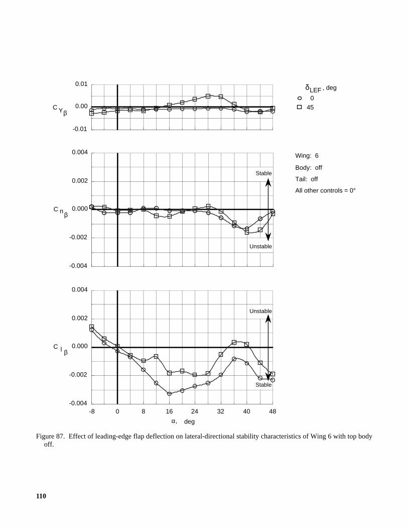
110
Figure 87. Effect of leading-edge flap deflection on lateral-directional stability characteristics of Wing 6 with top bodyoff.
Stable
Unstable
Unstable
Stable
Wing: 6
Body: off
Tail: off
All other controls = 0°
δLEF 0
45
, deg
-0.004
-0.002
0.000
0.002
0.004
C n β
C l β
484032241680-8-0.004
-0.002
0.000
0.002
0.004
α, deg
-0.01
0.00
0.01
C Yβ
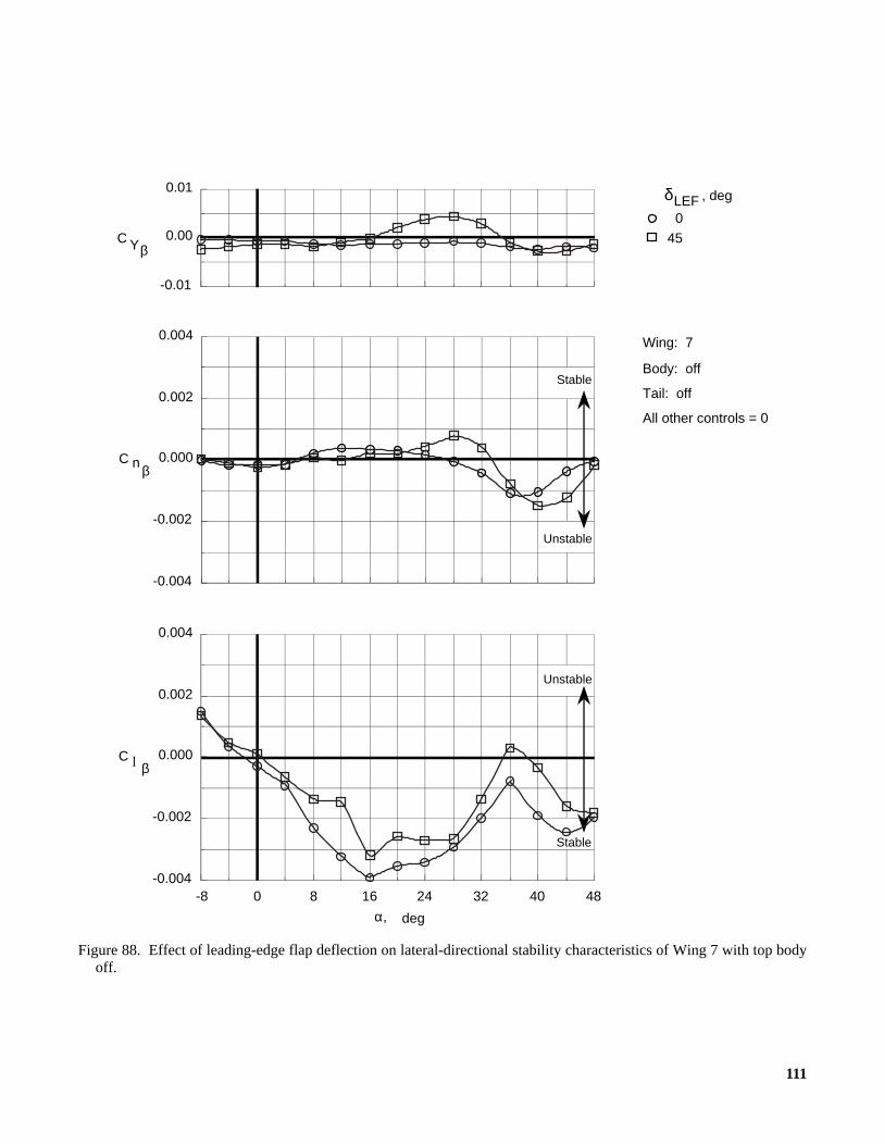
111
Figure 88. Effect of leading-edge flap deflection on lateral-directional stability characteristics of Wing 7 with top bodyoff.
Stable
Unstable
Unstable
Stable
Wing: 7
Body: off
Tail: off
All other controls = 0
δLEF 0
45
, deg
-0.004
-0.002
0.000
0.002
0.004
C n β
C l β
484032241680-8-0.004
-0.002
0.000
0.002
0.004
α, deg
-0.01
0.00
0.01
C Yβ
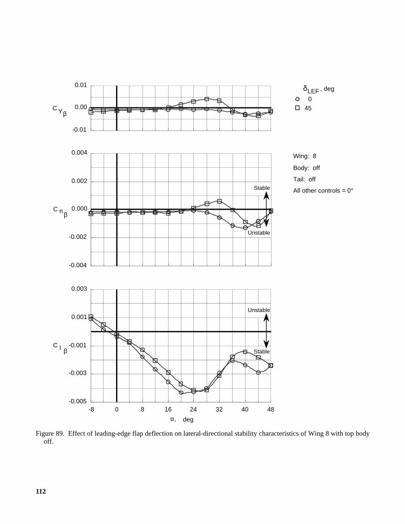
112
Figure 89. Effect of leading-edge flap deflection on lateral-directional stability characteristics of Wing 8 with top bodyoff.
Stable
Unstable
Unstable
Stable
Wing: 8
Body: off
Tail: off
All other controls = 0°
δLEF 0
45
, deg
-0.004
-0.002
0.000
0.002
0.004
C n β
C l β
484032241680-8-0.005
-0.003
-0.001
0.001
0.003
α, deg
-0.01
0.00
0.01
C Yβ

113
Figure 90. Effect of leading-edge flap deflections on lateral-directional stability characteristics of Wing 5 with wide topbody on.
Stable
Unstable
Unstable
Stable
Wing: 5
Body: wide
Tail: off
All other controls = 0°
δLEF 0
1530
45
, deg
60
-0.004
-0.002
0.000
0.002
0.004
C n β
C l β
484032241680-8-0.004
-0.002
0.000
0.002
0.004
α, deg
-0.01
0.00
0.01
C Yβ

114
Figure 91. Effect of leading-edge flap deflections on lateral-directional stability characteristics of Wing 6 with wide topbody on.
Stable
Unstable
Unstable
Stable
Wing: 6
Body: wide
Tail: off
All other controls = 0°
δLEF 0
1530
45
, deg
60
-0.004
-0.002
0.000
0.002
0.004
C n β
C l β
484032241680-8-0.004
-0.002
0.000
0.002
0.004
α, deg
-0.01
0.00
0.01
C Yβ

115
Figure 92. Effect of leading-edge flap deflections on lateral-directional stability characteristics of Wing 7 with wide topbody on.
Stable
Unstable
Unstable
Stable
Wing: 7
Body: wide
Tail: off
All other controls = 0°
δLEF 0
1530
45
, deg
60
-0.004
-0.002
0.000
0.002
0.004
C n β
C l β
484032241680-8-0.004
-0.002
0.000
0.002
0.004
α, deg
-0.01
0.00
0.01
C Yβ

116
Figure 93. Effect of leading-edge flap deflections on lateral-directional stability characteristics of Wing 8 with wide topbody on.
Stable
Unstable
Unstable
Stable
Wing: 8
Body: wide
Tail: off
All other controls = 0°
δLEF 0
1530
45
, deg
60
-0.004
-0.002
0.000
0.002
0.004
C n β
C l β
484032241680-8-0.005
-0.003
-0.001
0.001
0.003
α, deg
-0.01
0.00
0.01
C Yβ
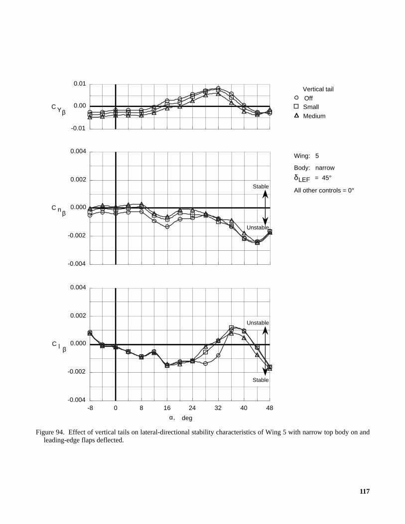
117
Figure 94. Effect of vertical tails on lateral-directional stability characteristics of Wing 5 with narrow top body on andleading-edge flaps deflected.
Vertical tail
OffSmall
Medium
Wing: 5
δLEF = 45°
Body: narrow
All other controls = 0°
Stable
Unstable
Unstable
Stable
-0.004
-0.002
0.000
0.002
0.004
C n β
C l β
484032241680-8-0.004
-0.002
0.000
0.002
0.004
α, deg
-0.01
0.00
0.01
C Yβ

118
Figure 95. Effect of vertical tails on lateral-directional stability characteristics of Wing 6 with narrow top body on andleading-edge flaps deflected.
Vertical tail
OffSmall
Medium
Wing: 6
δLEF = 45°
Body: narrow
All other controls = 0°
Stable
Unstable
Unstable
Stable
-0.004
-0.002
0.000
0.002
0.004
C n β
C l β
484032241680-8-0.004
-0.002
0.000
0.002
0.004
α, deg
-0.01
0.00
0.01
C Yβ
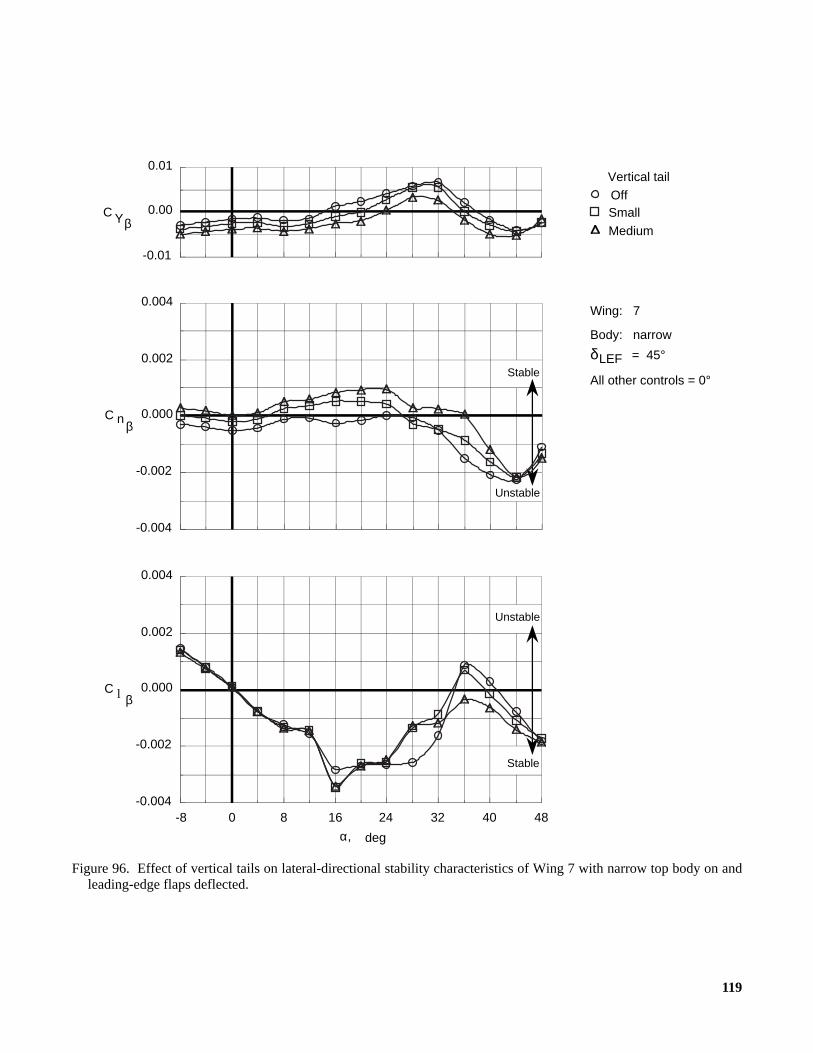
119
Figure 96. Effect of vertical tails on lateral-directional stability characteristics of Wing 7 with narrow top body on andleading-edge flaps deflected.
Vertical tail
OffSmall
Medium
Wing: 7
δLEF = 45°
Body: narrow
All other controls = 0°
Stable
Unstable
Unstable
Stable
-0.004
-0.002
0.000
0.002
0.004
C n β
C l β
484032241680-8-0.004
-0.002
0.000
0.002
0.004
α, deg
-0.01
0.00
0.01
C Yβ

120
Figure 97. Effect of vertical tails on lateral-directional stability characteristics of Wing 8 with narrow top body on andleading-edge flaps deflected.
Vertical tail
OffSmall
Medium
Wing: 8
δLEF = 45°
Body: narrow
All other controls = 0°
Stable
Unstable
Unstable
Stable
-0.004
-0.002
0.000
0.002
0.004
C n β
C l β
484032241680-8-0.005
-0.003
-0.001
0.001
0.003
α, deg
-0.01
0.00
0.01
C Yβ
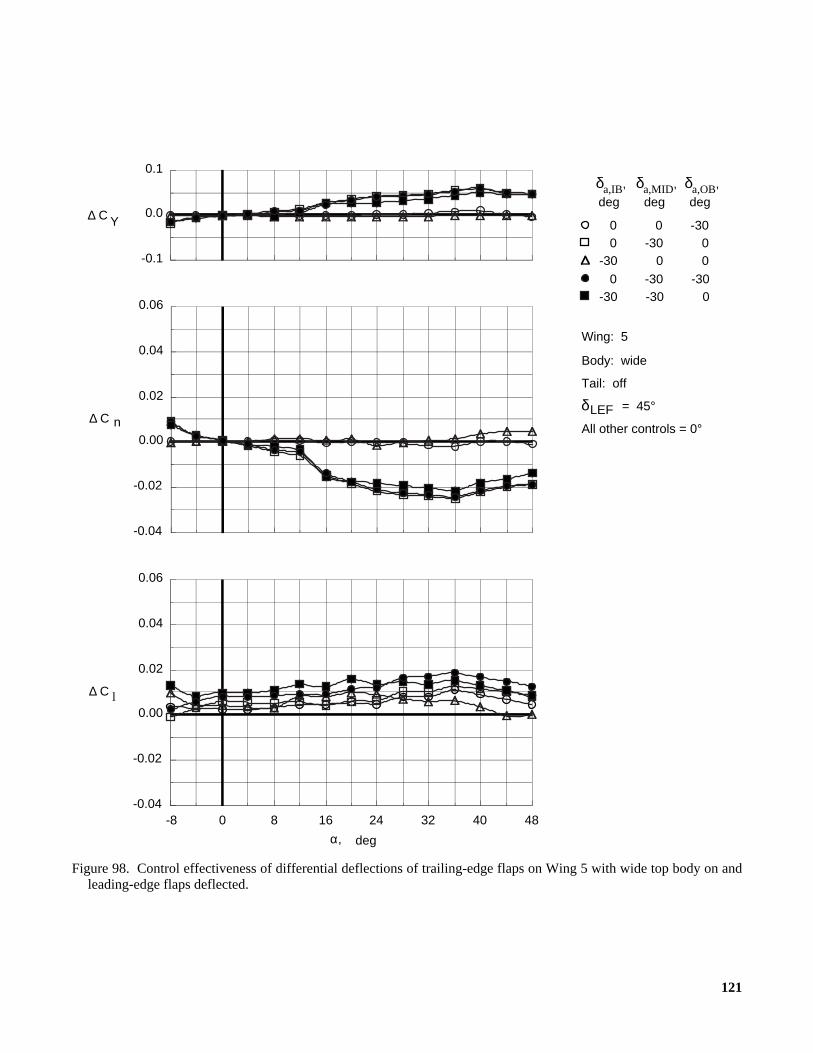
121
Figure 98. Control effectiveness of differential deflections of trailing-edge flaps on Wing 5 with wide top body on andleading-edge flaps deflected.
0 0 -30 0 -30 0-30 0 0
0 -30 -30-30 -30 0
Wing: 5
δLEF = 45°
Body: wide
Tail: off
All other controls = 0°
C l
484032241680-8-0.04
-0.02
0.00
0.02
0.04
0.06
α, deg
∆
-0.04
-0.02
0.00
0.02
0.04
0.06
C n∆
-0.1
0.0
0.1
C Y∆
δa,IB,
deg
δa,MID,
deg
δa,OB,
deg

122
Figure 99. Control effectiveness of differential deflections of trailing-edge flaps on Wing 6 with wide top body on andleading-edge flaps deflected.
0 0 -30 0 -30 0 0 -30 -30
-30 -30 0
Wing: 6
δLEF = 45°
Body: wide
Tail: off
All other controls = 0°
C l
484032241680-8-0.04
-0.02
0.00
0.02
0.04
0.06
α, deg
∆
-0.04
-0.02
0.00
0.02
0.04
0.06
C n∆
-0.1
0.0
0.1
C Y∆
δa,IB,
deg
δa,MID,
deg
δa,OB,
deg
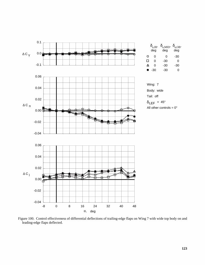
123
Figure 100. Control effectiveness of differential deflections of trailing-edge flaps on Wing 7 with wide top body on andleading-edge flaps deflected.
0 0 -30 0 -30 0 0 -30 -30
-30 -30 0
Wing: 7
δLEF = 45°
Body: wide
Tail: off
All other controls = 0°
C l
484032241680-8-0.04
-0.02
0.00
0.02
0.04
0.06
α, deg
∆
-0.04
-0.02
0.00
0.02
0.04
0.06
C n∆
-0.1
0.0
0.1
C Y∆
δa,IB,
deg
δa,MID,
deg
δa,OB,
deg

124
Figure 101. Control effectiveness of differential deflections of trailing-edge flaps on Wing 8 with wide top body on andleading-edge flaps deflected.
0 0 -30 0 -30 0-30 0 0
0 -30 -30
Wing: 8
δLEF = 45°
Body: wide
Tail: off
All other controls = 0°
C l
484032241680-8-0.04
-0.02
0.00
0.02
0.04
0.06
α, deg
∆
-0.04
-0.02
0.00
0.02
0.04
0.06
C n∆
-0.1
0.0
0.1
C Y∆
δa,IB,
deg
δa,MID,
deg
δa,OB,
deg

125
Figure 102. Control effectiveness of split deflections of right outboard trailing-edge flap on Wing 5 with wide top bodyon and leading-edge flaps deflected.
Wing: 5
δLEF = 45°
Body: wide
Tail: off
All other controls = 0°
-43-73
C l
484032241680-8-0.04
-0.02
0.00
0.02
0.04
0.06
α, deg
∆
-0.04
-0.02
0.00
0.02
0.04
0.06
C n∆
-0.1
0.0
0.1
C Y∆
δs,OB, deg
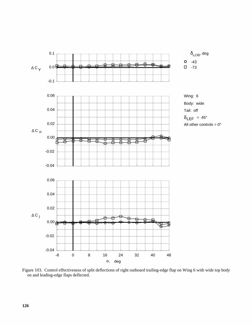
126
Figure 103. Control effectiveness of split deflections of right outboard trailing-edge flap on Wing 6 with wide top bodyon and leading-edge flaps deflected.
Wing: 6
δLEF = 45°
Body: wide
Tail: off
All other controls = 0°
-43-73
C l
484032241680-8-0.04
-0.02
0.00
0.02
0.04
0.06
α, deg
∆
-0.04
-0.02
0.00
0.02
0.04
0.06
C n∆
-0.1
0.0
0.1
C Y∆
δs,OB, deg
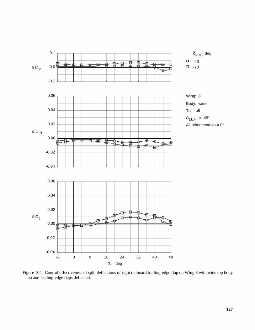
127
Figure 104. Control effectiveness of split deflections of right outboard trailing-edge flap on Wing 8 with wide top bodyon and leading-edge flaps deflected.
Wing: 8
δLEF = 45°
Body: wide
Tail: off
All other controls = 0°
-43-73
C l
484032241680-8-0.04
-0.02
0.00
0.02
0.04
0.06
α, deg
∆
-0.04
-0.02
0.00
0.02
0.04
0.06
C n∆
-0.1
0.0
0.1
C Y∆
δs,OB, deg

128
Figure 105. Control effectiveness of split deflections of right middle trailing-edge flap on Wing 5 with wide top body onand leading-edge flaps deflected.
Wing: 5
δLEF = 45°
Body: wide
Tail: off
All other controls = 0°
-43-73
C l
484032241680-8-0.04
-0.02
0.00
0.02
0.04
0.06
α, deg
∆
-0.04
-0.02
0.00
0.02
0.04
0.06
C n∆
-0.1
0.0
0.1
C Y∆
δs,MID, deg
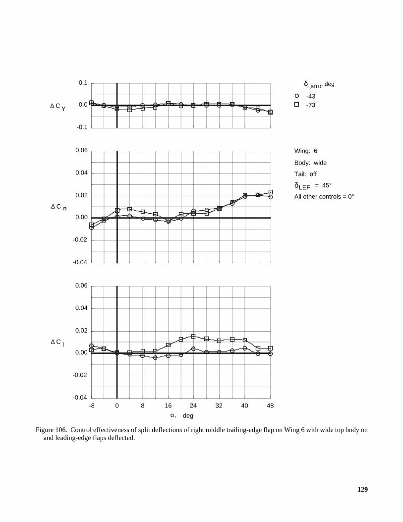
129
Figure 106. Control effectiveness of split deflections of right middle trailing-edge flap on Wing 6 with wide top body onand leading-edge flaps deflected.
Wing: 6
δLEF = 45°
Body: wide
Tail: off
All other controls = 0°
-43-73
C l
484032241680-8-0.04
-0.02
0.00
0.02
0.04
0.06
α, deg
∆
-0.04
-0.02
0.00
0.02
0.04
0.06
C n∆
-0.1
0.0
0.1
C Y∆
δs,MID, deg
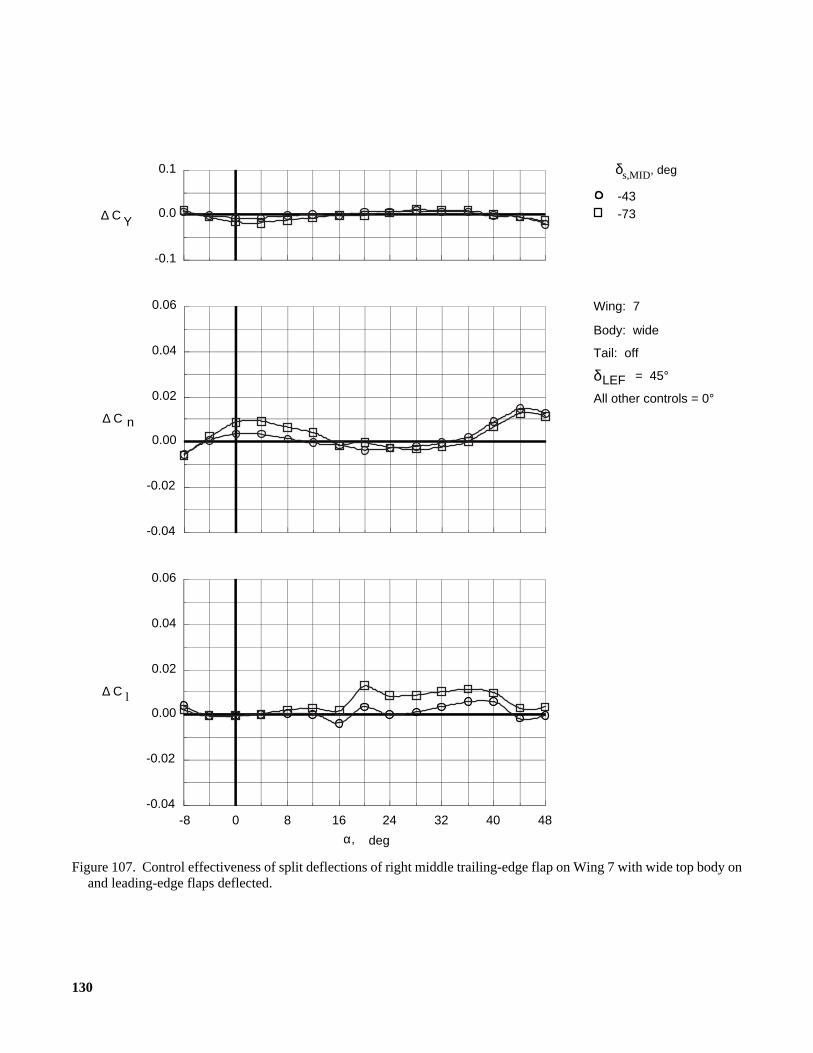
130
Figure 107. Control effectiveness of split deflections of right middle trailing-edge flap on Wing 7 with wide top body onand leading-edge flaps deflected.
Wing: 7
δLEF = 45°
Body: wide
Tail: off
All other controls = 0°
-43-73
C l
484032241680-8-0.04
-0.02
0.00
0.02
0.04
0.06
α, deg
∆
-0.04
-0.02
0.00
0.02
0.04
0.06
C n∆
-0.1
0.0
0.1
C Y∆
δs,MID, deg
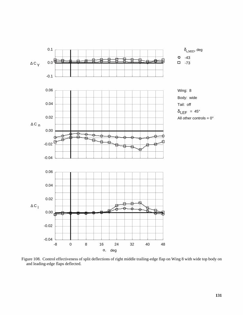
131
Figure 108. Control effectiveness of split deflections of right middle trailing-edge flap on Wing 8 with wide top body onand leading-edge flaps deflected.
Wing: 8
δLEF = 45°
Body: wide
Tail: off
All other controls = 0°
-43-73
C l
484032241680-8-0.04
-0.02
0.00
0.02
0.04
0.06
α, deg
∆
-0.04
-0.02
0.00
0.02
0.04
0.06
C n∆
-0.1
0.0
0.1
C Y∆
δs,MID, deg

132
Figure 109. Control effectiveness of deflections of small vertical tails on Wing 5 with narrow top body on and leading-edge flaps deflected.
δLEF = 45°
All other controls = 0°
, deg
-10
δ r
Wing: 5
Tail: small
Body: narrow
-30
C l
484032241680-8-0.04
-0.02
0.00
0.02
0.04
0.06
α, deg
∆
-0.04
-0.02
0.00
0.02
0.04
0.06
C n∆
-0.1
0.0
0.1
C Y∆

133
Figure 110. Control effectiveness of deflections of small vertical tails on Wing 6 with narrow top body on and leading-edge flaps deflected.
δLEF = 45°
All other controls = 0°
, deg
-10
δ r
Wing: 6
Tail: small
Body: narrow
-30
C l
484032241680-8-0.04
-0.02
0.00
0.02
0.04
0.06
α, deg
∆
-0.04
-0.02
0.00
0.02
0.04
0.06
C n∆
-0.1
0.0
0.1
C Y∆

134
Figure 111. Control effectiveness of deflections of small vertical tails on Wing 7 with narrow top body on and leading-edge flaps deflected.
δLEF = 45°
All other controls = 0°
, deg
-10
δ r
Wing: 7
Tail: small
Body: narrow
-30
C l
484032241680-8-0.04
-0.02
0.00
0.02
0.04
0.06
α, deg
∆
-0.04
-0.02
0.00
0.02
0.04
0.06
C n∆
-0.1
0.0
0.1
C Y∆

135
Figure 112. Control effectiveness of deflections of small vertical tails on Wing 8 with narrow top body on and leading-edge flaps deflected.
δLEF = 45°
All other controls = 0°
, deg
-10
δ r
Wing: 8
Tail: small
Body: narrow
-30
C l
484032241680-8-0.04
-0.02
0.00
0.02
0.04
0.06
α, deg
∆
-0.04
-0.02
0.00
0.02
0.04
0.06
C n∆
-0.1
0.0
0.1
C Y∆
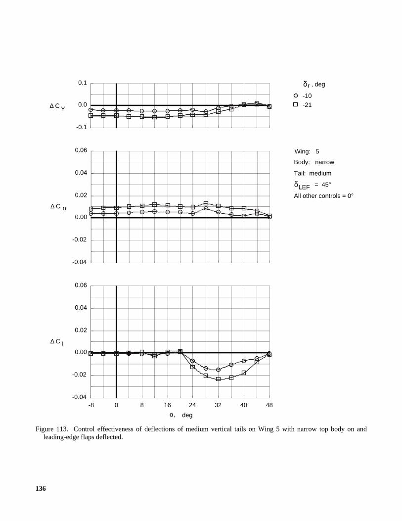
136
Figure 113. Control effectiveness of deflections of medium vertical tails on Wing 5 with narrow top body on andleading-edge flaps deflected.
δLEF = 45°
All other controls = 0°
, deg
-10
δ r
Wing: 5
Tail: medium
Body: narrow
-21
C l
484032241680-8-0.04
-0.02
0.00
0.02
0.04
0.06
α, deg
∆
-0.04
-0.02
0.00
0.02
0.04
0.06
C n∆
-0.1
0.0
0.1
C Y∆
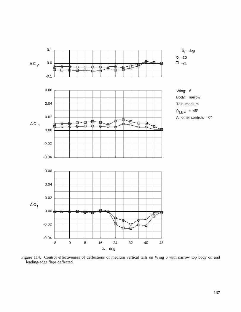
137
Figure 114. Control effectiveness of deflections of medium vertical tails on Wing 6 with narrow top body on andleading-edge flaps deflected.
δLEF = 45°
All other controls = 0°
, deg
-10
δ r
Wing: 6
Tail: medium
Body: narrow
-21
C l
484032241680-8-0.04
-0.02
0.00
0.02
0.04
0.06
α, deg
∆
-0.04
-0.02
0.00
0.02
0.04
0.06
C n∆
-0.1
0.0
0.1
C Y∆
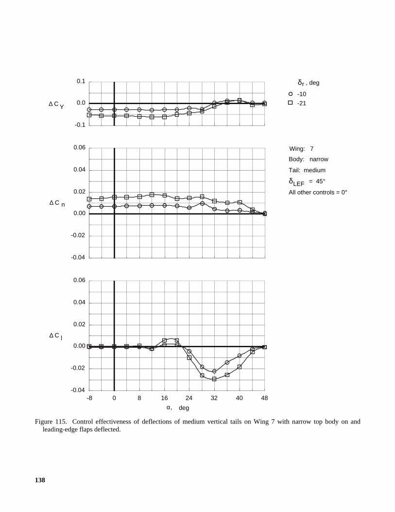
138
Figure 115. Control effectiveness of deflections of medium vertical tails on Wing 7 with narrow top body on andleading-edge flaps deflected.
δLEF = 45°
All other controls = 0°
, deg
-10
δ r
Wing: 7
Tail: medium
Body: narrow
-21
-0.04
-0.02
0.00
0.02
0.04
0.06
C n∆
-0.1
0.0
0.1
C Y∆
C l
484032241680-8-0.04
-0.02
0.00
0.02
0.04
0.06
α, deg
∆
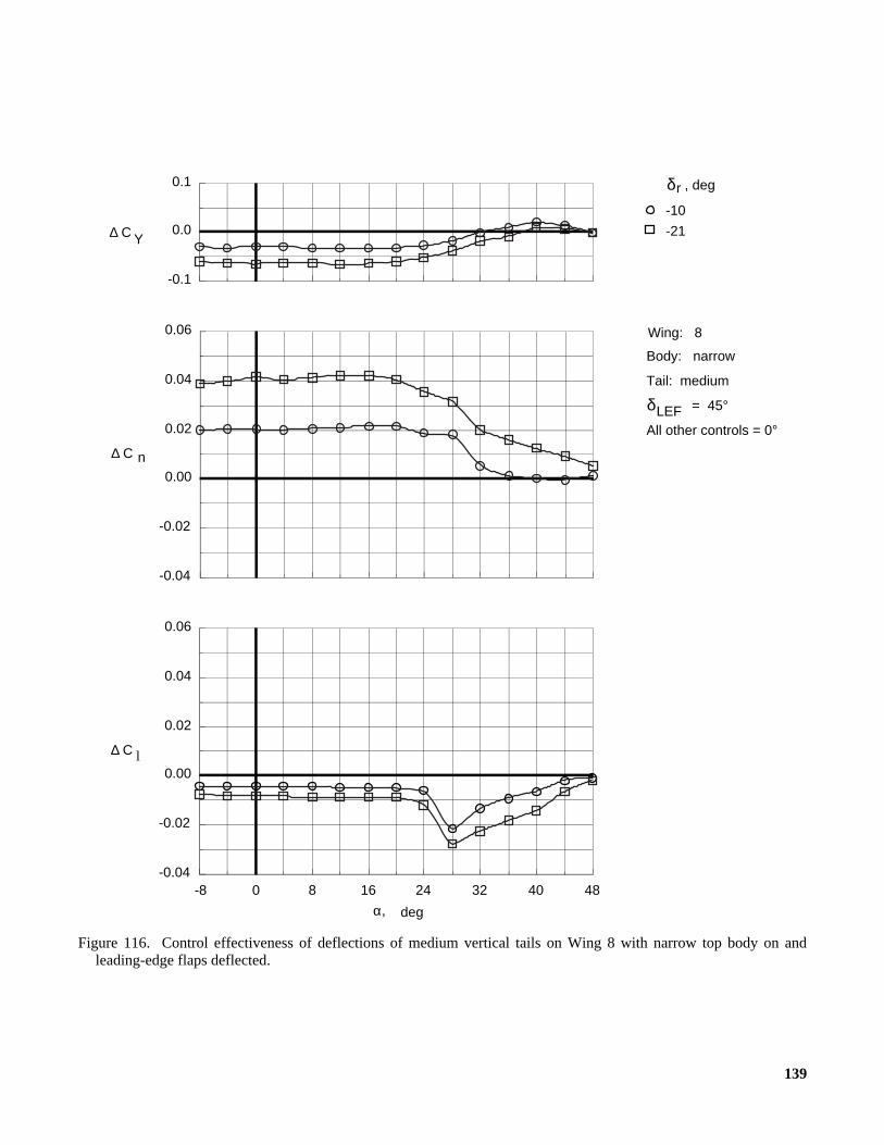
139
Figure 116. Control effectiveness of deflections of medium vertical tails on Wing 8 with narrow top body on andleading-edge flaps deflected.
δLEF = 45°
All other controls = 0°
, deg
-10
δ r
Wing: 8
Tail: medium
Body: narrow
-21
C l
484032241680-8-0.04
-0.02
0.00
0.02
0.04
0.06
α, deg
∆
-0.04
-0.02
0.00
0.02
0.04
0.06
C n∆
-0.1
0.0
0.1
C Y∆
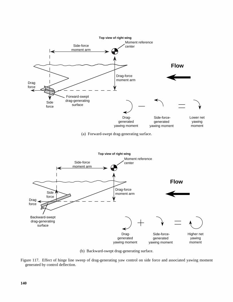
140
(a) Forward-swept drag-generating surface.
(b) Backward-swept drag-generating surface.
Figure 117. Effect of hinge line sweep of drag-generating yaw control on side force and associated yawing momentgenerated by control deflection.
Moment reference centerSide-force
moment arm
Drag-force moment arm
Forward-swept drag-generating
surface
Drag force
Sideforce
Drag-generated
yawing moment
Side-force-generated
yawing moment
Lower net yawing moment
Top view of right wing
Flow
Moment reference centerSide-force
moment arm
Drag-force moment arm
Backward-swept drag-generating
surface
Drag force
Sideforce
Drag-generated
yawing moment
Side-force-generated
yawing moment
Higher net yawing moment
Flow
Top view of right wing

Form ApprovedOMB No. 0704-0188
Public reporting burden for this collection of information is estimated to average 1 hour per response, including the time for reviewing instructions, searching existing data sources,gathering and maintaining the data needed, and completing and reviewing the collection of information. Send comments regarding this burden estimate or any other aspect of thiscollection of information, including suggestions for reducing this burden, to Washington Headquarters Services, Directorate for Information Operations and Reports, 1215 JeffersonDavis Highway, Suite 1204, Arlington, VA 22202-4302, and to the Office of Management and Budget, Paperwork Reduction Project (0704-0188), Washington, DC 20503.
1. AGENCY USE ONLY (Leave blank) 2. REPORT DATE 3. REPORT TYPE AND DATES COVERED
4. TITLE AND SUBTITLE 5. FUNDING NUMBERS
6. AUTHOR(S)
7. PERFORMING ORGANIZATION NAME(S) AND ADDRESS(ES)
9. SPONSORING/MONITORING AGENCY NAME(S) AND ADDRESS(ES)
11. SUPPLEMENTARY NOTES
8. PERFORMING ORGANIZATIONREPORT NUMBER
10. SPONSORING/MONITORINGAGENCY REPORT NUMBER
12a. DISTRIBUTION/AVAILABILITY STATEMENT 12b. DISTRIBUTION CODE
13. ABSTRACT (Maximum 200 words)
14. SUBJECT TERMS
17. SECURITY CLASSIFICATIONOF REPORT
18. SECURITY CLASSIFICATIONOF THIS PAGE
19. SECURITY CLASSIFICATIONOF ABSTRACT
20. LIMITATIONOF ABSTRACT
15. NUMBER OF PAGES
16. PRICE CODE
NSN 7540-01-280-5500 Standard Form 298 (Rev. 2-89)Prescribed by ANSI Std. Z39-18298-102
REPORT DOCUMENTATION PAGE
September 1995 Technical Memorandum
Low-Speed Wind-Tunnel Investigation of the Stability and ControlCharacteristics of a Series of Flying Wings With Sweep Angles of 70° WU 505-68-30-01
Holly M. Ross, Scott P. Fears, and Thomas M. Moul
L-17460
NASA TM-4671
Ross and Moul: Langley Research Center, Hampton, VA, Fears: Lockheed Engineering & Sciences Company,Hampton, VA.
A wind-tunnel investigation was conducted in the Langley 12-Foot Low-Speed Tunnel to study the low-speedstability and control characteristics of a series of four flying wings over an extended range of angle of attack(−8° to 48°). Because of the current emphasis on reducing the radar cross section (RCS) of new military aircraft,the planform of each wing was composed of lines swept at a relatively high angle of 70°, and all the trailing edgesand control surface hinge lines were aligned with one of the two leading edges. Three arrow planforms with differ-ent aspect ratios and one diamond planform were tested. The models incorporated leading-edge flaps for improvedlongitudinal characteristics and lateral stability and had three sets of trailing-edge flaps that were deflected differen-tially for roll control, symmetrically for pitch control, and in a split fashion for yaw control. Three top body widthsand two sizes of twin vertical tails were also tested on each model. A large aerodynamic database was compiledthat could be used to evaluate some of the trade-offs involved in the design of a configuration with a reduced RCSand good flight dynamic characteristics.
Flying wings; Arrow wings; Diamond wings; Reduced radar cross section;Stability and control; High angle of attack
141
A07
NASA Langley Research CenterHampton, VA 23681-0001
National Aeronautics and Space AdministrationWashington, DC 20546-0001
Unclassified–UnlimitedSubject Category 05Availability: NASA CASI (301) 621-0390
Unclassified Unclassified Unclassified