low-speed serial data trigger, decode, measure/graph,...
TRANSCRIPT

Low-speed Serial Data Trigger, Decode, Measure/Graph, and Eye Diagrams
Key Features
More than 20 supported standards: • I2C • SPI, SPI DDR, Simplified SPI • UART and RS-232 • USB 1.x, 2.0 and USB 2.0 HSIC • CAN and CAN FD • LIN • FlexRay • SENT • ARINC 429 • MIL-STD-1553 • SPACEWIRE • 10/100 Base-T Ethernet, EtherCAT • DPHY • DigRF 3G, DigRF v4 • I2S, incl. LJ, RJ, TDM • Manchester • NRZ
Most powerful, flexible triggering capabilities
Intuitive, color-coded decode overlays
Single protocol results table supports up to 4 decoders at one time
Unique measure/graph capabilities: • Automated timing measurements • Serial DAC - extract digital data and plot it as a waveform • Bus parameters
Physical layer eye diagrams
Highest Performance TriggersDesigned by people who know the standards, with the unique capabilities you want to isolate unusual events. Conditional data triggering permits maximum flexibility, and highly adaptable error frame triggering is available to isolate error conditions. Frame definition allows grouping of UART or SPI packets into message frames for customization.
The Best Serial Decoder Decoded protocol information is color-coded to specific portions of the serial data waveform and transparently overlaid for an intuitive, easy-to-understand visual record. All decoded protocols are displayed in a single time-interleaved table. Touch a row in the interactive table to quickly zoom to a packet of interest and easily search through long records for specific protocol events using the built-in search feature.
Measure/Graph Tools for Validation EfficiencyQuickly validate cause and effect with automated timing measurements to or from an analog signal or another serial message. Make multiple measurements in a single long acquisition to quickly acquire statistics during corner-case testing. Serial (digital) data can be extracted to an analog value and graphed to monitor system performance over time, as if it was probed directly. Complete validation faster and gain better insight.
Eye Diagrams & Physical LayerRapidly display an eye diagram of your packetized low-speed serial data signal without additional setup time. Use eye parameters to quantify system performance and apply a standard or custom mask to identify anomalies. Mask failures can be indicated and can force the scope into Stop mode.
Teledyne LeCroy’s Trigger (T), Decode (D), Measure/Graph (M or G) and Eye Diagram and Physical Layer (E or P) options are the best in the industry and nearly universally available across the entire Teledyne LeCroy oscilloscope product line.

2
THIGHEST PERFORMANCE TRIGGERS
Conditional DATA SetupEvery Teledyne LeCroy low-speed serial trigger that incorporates DATA trigger permits a conditional (<. <=, =, >, >=, <>, inside a range, outside a range) setup for the DATA condition. This is especially useful in situations where abnormal events should be monitored, such as when a temperature sensor transmitting via I2C exceeds a maximum temperature, or a CAN node broadcasts a low or high engine RPM or coolant pressure. Furthermore, data for triggering can be specifically isolated in very long byte streams to specific bit locations, even those which span data bytes.
Support for Many Proprietary ProtocolsMany proprietary serial protocols make use of the common UART (single Data line) or USART (Clock and Data lines, e.g., SPI) byte structures, with multiple bytes grouped into proprietary protocol definitions. Our highly flexible UART byte and SPI format definitions accommodate nearly any customer need, and the UART or SPI bytes can be defined to be part of a single “message frame” through use of our Interframe Setup. Then, the trigger pattern setup can isolate any byte value, e.g., an ID, or a DATA string value, that is part of your proprietary protocol message definition.
Every serial trigger we design exhibits deep knowledge of the standard. Most serial triggers work with digital (MSO) inputs, or the EXT input for the Clock line so as to conserve analog channels. Each serial trigger has some unique aspect for high performance, such as:
• I2C trigger permits triggering on data in a specific location of an up to 2048 byte I2C EEPROM read or write.
• UART or SPI bytes can be combined into a single “message frame” - trigger on custom protocols based on UART or SPI byte blocks.
• UART supports 9-bit “address” or “wakeup” mode triggering.
• CAN, CAN FD, LIN, FlexRay and MIL-STD-1553 permit conditional ID/Address triggering.
• CAN and CAN FD permit triggering symbolically using a DBC file.
• USB 2.0 and MIL-STD-1553 triggers permits complex transaction definition and triggering. High performance and a wide range of
support for serial data standards
Conditional data triggering selections provide highest flexibility
Byte mode (top) treats each byte uniquely. Message Frame mode (bottom) groups bytes into on single, long multi-byte message
AB
I2C SPI UART RS-232 FlexRay LIN CAN CAN FD USB2
AB
I2C SPI UART RS-232 FlexRay LIN CAN CAN FD USB2
AB
I2C SPI UART RS-232 FlexRay LIN CAN CAN FD USB2
AB
I2C SPI UART RS-232 FlexRay LIN CAN CAN FD USB2
AB
I2C SPI UART RS-232 FlexRay LIN CAN CAN FD USB2
AB
I2C SPI UART RS-232 FlexRay LIN CAN CAN FD USB2
AB
I2C SPI UART RS-232 FlexRay LIN CAN CAN FD USB2
AB
I2C SPI UART RS-232 FlexRay LIN CAN CAN FD USB2
AB
I2C SPI UART RS-232 FlexRay LIN CAN CAN FD USB2

3
DSIMPLY THE BEST SERIAL DECODER
Intuitive, Color-Coded OverlaysA transparent overlay with color-coding for specific portions of each protocol and the entire message frame makes it easy to understand your serial data information. Unlike other solutions, with protocol decode information away from the signal, our solution correlates the waveform and the protocol decode directly on the display. As the acquisition length is expanded or shortened, the decode overlay will adjust to show you just the right amount of information.
Pattern SearchAll decoders provide ability to search through a long record of decoded data by using a variety of search criteria, or values, or simply finding the next occurrence. Pattern Search automatically creates a zoom trace of the acquired waveform and displays the selected location complete with the transparent color-coded overlay.
Interactive Table Summarizes ResultsTurn the oscilloscope into a protocol analyzer with a tabular display of decoded information. Customize the table to show only the data of interest and touch a message in the table to automatically zoom to it and display it on the screen. Export the table for offline analysis. Up to four different decoded signals of any type may be simultaneously displayed in the table.
Our serial decode, search and table tools work exactly the way you want. These tools are the industry standard for turning your oscilloscope into a protocol analyzer with fast and intuitive correlation of protocol data to the physical layer waveforms.
4
MMEASUREMENT / GRAPHING - EXTEND YOUR KNOWLEDGE
Key Features
Timing measurements • Serial Message to Analog Signal • Analog Signal to Serial Message • Serial Message to Serial Message
Serial DAC measurement/graphing
Bus status measurements
Automated – quickly gather statistics, display Histograms
Quickly correlate cause-effect timing relationships to other events
Conditional filtering
Supported for • I2C • SPI, SPI DDR, Simplified SPI, Custom SPI • UART • RS-232 • USB 1.x and 2.0 • CAN • CAN FD • LIN • FlexRay • ARINC 429 • MIL-STD-1553 • DigRF 3G • DigRF v4 • I2S, incl. LJ, RJ, TDM (note: Serial
DAC graph, or “G” capability only)
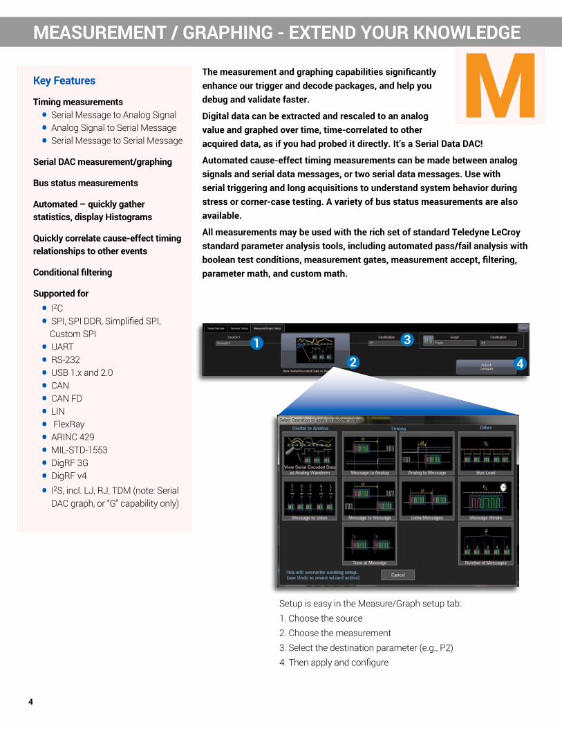
The measurement and graphing capabilities significantly enhance our trigger and decode packages, and help you debug and validate faster.
Digital data can be extracted and rescaled to an analog value and graphed over time, time-correlated to other acquired data, as if you had probed it directly. It’s a Serial Data DAC!
Automated cause-effect timing measurements can be made between analog signals and serial data messages, or two serial data messages. Use with serial triggering and long acquisitions to understand system behavior during stress or corner-case testing. A variety of bus status measurements are also available.
All measurements may be used with the rich set of standard Teledyne LeCroy standard parameter analysis tools, including automated pass/fail analysis with boolean test conditions, measurement gates, measurement accept, filtering, parameter math, and custom math.
Setup is easy in the Measure/Graph setup tab: 1. Choose the source2. Choose the measurement3. Select the destination parameter (e.g., P2)4. Then apply and configure
12
3
4

5
MApplies a Track math operator to the Message to Value measurement to view Serial Encoded Data as an Analog Waveform
Shown above is a long acquisition of a CAN serial data signal (top waveform) that contains embedded digital data for steering wheel angle rate of change (deg/s, or Hz). The Message to Value parameter was configured to locate and extract the digital steering wheel angle range data from particular locations in specific CAN serial messages, and then converted from digital to analog form with proper re-scaling and physical units. The serial data DAC waveform (bottom waveform) is shown in the lower grid.
Decoded data content of data payload of a protocol message meeting conditions.
Serial Data DAC and Graphing Tools Digital data can be extracted from specific locations in the serial data message using the Message to Value measurement param-eter - a serial data DAC. This information can then be displayed as a measurement parameter value(s), or it can be viewed as a time-correlated waveform displaying the measurement value over time - as if you were able to probe and acquire it directly. Use the long acquisition time of the oscilloscope to understand how the data changes over long periods of time, in conjunction with other system behaviors.
Some examples of the usefulness of this capability are:
• Viewing I2C or SPI temperature sensor data
• Viewing DigRF 3G radio frequency I and Q modulated signals
• Viewing CAN wheel speed information used by an ABS
• Viewing reconstructed analog audio from serial I2S streams

6
MMEASUREMENT / GRAPHING - IMPROVE VALIDATION TIME
Analog to Message Computes the time difference from a protocol message meeting specified conditions to the crossing of a threshold on an analog signal.
Message to Message Computes the time difference from a protocol message meeting specified conditions to another protocol message meeting specified conditions
Message to Analog Computes the time difference from a protocol message meeting specified conditions to the crossing of a threshold on an analog signal.
DeltaMessage Time Computes the time difference between two messages on a single decoded line.
Time@Message Time from Trigger to each protocol message meeting specified conditions.
Automated Timing MeasurementsUtilize a serial trigger to isolate a specific message and then measure a cause-effect timing relationship with a subsequent analog signal, or vice versa. But instead of manually measuring the timing with cursors, use these tools to automate the measurement and return thousands of values quickly as your system undergoes stress testing. Automate the measurement and validation of gateway latency times from one serial message to another (e.g. CAN to LIN or low-speed CAN to high-speed CAN, or CAN to FlexRay) without having to manually use cursors or compare values and times in a protocol table. Quickly understand bus latency times or arbitration behaviors by measuring the difference between two messages on a single decoded waveform. Dramatically improve your validation efficiency and time to insight
Use the Message to Analog measurement to find the time between
an I2C data packet and a control signal on another channel. Multiple
measurements in one or more triggers could be made to understand behaviors over time or under different
operation conditions

7
MMessage Bus Load % Computes the load of user defined message in percent on the bus
Message Bit Rate Computes the bitrate of the user specified messages on the decoded trace.
Number of Messages Computes the number of message matching user definition in a decoded trace.
Bus Status MeasurementsThe bus status measurements Bus Load, Message Bitrate, and Number of Messages, give an overall status of the decode protocol to quickly learn if the bus is over utilized and to verify the bit rate matches expectations.
The Perfect Oscilloscopes for the TDME Options
Teledyne LeCroy HDO and WaveRunner oscilloscopes are the perfect oscilloscope platforms to utilize the TD and TDME toolsets.
Teledyne LeCroy’s HDO 12-bit oscilloscopes provide 12-bit resolution and either 4 or 8 analog input channels up to 1 GHz with MSO digital input options. These oscilloscopes are have powerful standard toolsets for debugging deeply embedded designs with analog, digital, serial data, and sensor signals. Their 12-bit resolution is ideal for measuring sensor signals and correlating them to other system activities. 8 analog input channels provides more ability to correlate more signals to each other.
Teledyne LeCroy WaveRunner oscilloscopes, such as the WaveRunner 8000 Series, are also extensively used for embedded system debug. Their standard toolsets complement the TDME packages extremely well.

8
EEYE DIAGRAM AND PHYSICAL LAYER
Key Features
Up to four simultaneous Eye Diagrams
Simple to set up - one button push
Include standard or custom masks. Create your own masks.
Eye parameters
Mask failure indication
Failure locator trace waveform
Pass/Fail with STOP on failure
Up to 4 Simultaneous Eye DiagramsUp to four serial data signals can be decoded and displayed as eye diagrams at one time. These can be different protocols, or the same protocol measured at different points (e.g., transmit and receive, different nodes, or different standard-defined test points). Apply a user-defined filter to each eye diagram to only display specific signals in the eye.
Eye diagrams “slice” each bit and overlay them to get a consolidated view of signal quality. Intrusions into the eye opening or onto a mask indicate potential problems.
Eye Diagram Measurement ParametersQuantify physical layer signal quality in the eye by applying parameters for Eye Height, Eye Width, and Number of Mask Failures. Some packages (e.g. FlexRay TDMP) go a step further and include additional measurements defined in the standard.
Eye Diagrams are “bit-sliced” views of the physical layer serial data waveforms. They provide a fast, intuitive way to understand physical layer signal integrity. Eye Diagrams may be combined with masks and mask failure indications, and eye (opening) parameters. Protocols with challenging topologies (e.g. FlexRay) provide even more advanced measurement capabilities.

9
EMASK AND MASK FAILURE INDICATION
Mask and Mask Failure IndicationA user-defined or pre-defined mask may be added to the eye diagram so as to objectively evaluate if the physical layer signal intrudes too far into the eye opening. Apply a filter to include or exclude specific messages from the Eye so as to determine failure source (e.g., messages from a specific node or with a specific ID). Mask failures are indicated with a red circle and can be displayed in a table. Touch the failure table to open a zoom of the failed area for further inspection
PHYSICAL LAYER (EYE + ADVANCED MEASUREMENTS)
Some standards, due to their speed or nodal complexity, provide specific guidance on what eye diagrams or measurements should be made and exactly how they should be performed. FlexRay, and MIPI DPHY are examples. In these cases, the Eye Diagram (“E”) capability is augmented with additional specialized “P” capability (for Physical Layer Measurements), per the standard. In these cases, the “E” capabilities previously described are also available.
P

10
I2C
Key Features
Set an ACK condition (ACK, NO ACK, Don’t Care) in all frame trigger setups
Does not require clock trace to be displayed during decode
EEPROM read/write 2048 byte trigger capability
Frame Length trigger capability
Address can include a R/W bit, or define as Don’t Care
Use analog or digital (MSO) inputs for acquisition and triggering.
EXT input may be used for clock signal
More Trigger ChoicesIn addition to typical Start/Stop/ReStart, NoAck, Address and Address+Data triggers, Teledyne LeCroy provides triggering for EEPROM read/writes up to 2048 bytes long and for Frame Length. Address-based triggers permit an additional ACK condition (ACK present, NO ACK present, or DON’T CARE). and selection to include a R/W bit in a 7-bit trigger.
More Flexibility for Address-based TriggersAddress-based triggers permit an additional ACK condition (ACK present, NO ACK present, or DON’T CARE). and selection to define the transfer direction as a READ, WRITE or DON’T CARE (using R/W bit in a 7-bit trigger, or R/W Direction selection in a 10-bit trigger).

11
SPECIFICATIONS
I2Cbus TD and I2Cbus TDMEDefinitionSource Setup Select Source for Clock and DataTrigger CapabilityFormat Hexadecimal or Binary. ADDRESS and DATA can be set up with different formatsTrigger Setup Trigger on START, ReSTART, STOP, Missing ACK, ADDR, DATA, ADDR+DATA, ADDR+DATA FRAME LENGTH, EEPROM DATA TRANSFERADDRESS Setup Specify one ADDRESS with condition of “=”.
7 or 10 bit ADDRESS supported with full Read, Write, or R/W=”Don’t Care” selectability on both 7 and 10 bit ADDRESSes.Choose to Trigger on address values that include/don’t include R/W bit in address value.
DATA Setup ADDRESS+DATA Trigger Type:Hexadecimal: # Data Bytes = 0 to 12. Data can be defined by nibble. Binary: Any combination of 0,1, or X for 1-96 bitsData pattern can be set to start at any location in the 12 Byte / 96 bit sequence. ADDRESS+ DATA FRAME LENGTH Trigger Type: # Data Bytes = 0 to 2047.EEPROM DTA TRANSFER Trigger Type:# Data Bytes = 0 to 12. Data can be defined by nibble. Data pattern can be set to start at the beginning of any byte in an up to 2048 byte sequence.
DATA Conditions <=, <, =, >, >=, <>, IN RANGE, OUT OF RANGE, or DON’T CAREACK Conditions For any ADDR, ADDR+DATA, ADDR+DATA FRAME LENGTH, or EEPROM DATA TRANSFER setup, select an ACK Condition of ACK, NO
ACK, and DON’T CARE.Bit Rates Full range over I2C specification for Standard, Fast, Fast-Mode Plus, and High-Speed modes. Auto-detected.Trigger Input Any analog Channel or Digital input, or the EXT input. Clock may be input to EXT to conserve available analog Channels.Decode + Search CapabilityFormat Hexadecimal, Binary, ASCIIDecode Setup Threshold definition required. Default is to Percent amplitude.
Choose to Decode address values including/not including the R/W bit in address value.Decode Input Any analog Channel, Memory or Math trace, and any Digital trace.
Clock channel may be turned OFF and data will still decode (reduces screen clutter) # of Decodes Up to 4 buses may be decoded at one time. In addition, zooms can be displayed (with decoded information).Visual Aid Color Coding for FRAME, START/ReSTART bit, ADDR, R/W, DATA, ACK, NACK, and STOP bit.
Decode information is intelligently annotated based on timebase setting, and overlaid on acquired waveform.Table Configure, Export Table
Display 1 to 20 rows of decoded information for up to 4 different protocols or decodes in time order in a single table. Displayed information includes Index, Timestamp, and other various protocol-specific information. Table permits scrolling, touch to zoom, export to .csv file, and special display of long data or other patterns.
Pattern Search Search for Previous or Next ADDRESS, PACKET, or DATA in hexadecimal format.
I2Cbus TDME onlyMeasure / Graph CapabilitySerial Data Digital-to-Analog Conversion (DAC)
Message to Value measurement parameter extracts and converts a specified portion of the data in an up to 2048 byte data/payload in the serial message and displays it as an analog decimal value. Supports different data encoding formats, message filtering to specific IDs, and complete re-scaling with unit conversion. Serial DAC Waveform plots the converted digital-to-analog data as a waveform time-correlated to other acquisition data, and view the change in data over time.
Timing Measurements
Message to Analog, Analog to Message, Message to Message, ΔMessage Time (identical message on same decoder), Time@Message (time from trigger) measurement parameters. Serial Message may be defined by “ID =” (where applicable) and user-defined DATA condition of <=, <, =, >, >=, <>, IN RANGE, or OUT OF RANGE in any location in up to 2048 bits of data. Analog Signal may be defined by Slope (pos, neg), Level (abs or %) with Hysteresis setting. Holdoff may be set on the Analog Signal by either Time or Events (up to 1000) to preclude unwanted measurements.
Bus Status Measurements
Number of Messages, Message Bit Rate, Message Bus Load %: Serial Message may be defined by “ID =” (where applicable) and user-defined “DATA <=, <, =, >, >=, <>, in range, out of range” in any location in up to 2048 bits of data.
Eye Diagram CapabilitySetup Create up to four simultaneous Eye Diagrams (one per Serial Decoder) of the physical layer signal(s). Eye Style selectable as color- or
analog-persisted. Eye Saturation adjustable from 0 to 100%.Eye Parameters Eye Height, Eye Width, (Number of) Mask HitsEye Mask Create a custom Mask using the free Teledyne LeCroy MaskMaker software utility. Store custom masks for later recall and use. Failure Indication and Location
Mask Failure Indication ON or OFF (ON = indicated with a red circle). Mask Failure Location trace waveform displayed and interactive with Eye Mask failure table. Supports STOP trigger on Mask Failure.
12
SPI
Key Features
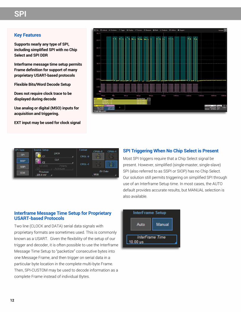
Supports nearly any type of SPI, including simplified SPI with no Chip Select and SPI DDR
Interframe message time setup permits Frame definition for support of many proprietary USART-based protocols
Flexible Bits/Word Decode Setup
Does not require clock trace to be displayed during decode
Use analog or digital (MSO) inputs for acquisition and triggering.
EXT input may be used for clock signal
SPI Triggering When No Chip Select is PresentMost SPI triggers require that a Chip Select signal be present. However, simplified (single-master, single-slave) SPI (also referred to as SSPI or SIOP) has no Chip Select. Our solution still permits triggering on simplified SPI through use of an Interframe Setup time. In most cases, the AUTO default provides accurate results, but MANUAL selection is also available.
Interframe Message Time Setup for Proprietary USART-based ProtocolsTwo line (CLOCK and DATA) serial data signals with proprietary formats are sometimes used. This is commonly known as a USART. Given the flexibility of the setup of our trigger and decoder, it is often possible to use the Interframe Message Time Setup to “packetize” consecutive bytes into one Message Frame, and then trigger on serial data in a particular byte location in the complete multi-byte Frame. Then, SPI-CUSTOM may be used to decode information as a complete Frame instead of individual Bytes.

13
SPECIFICATIONS
SPIbus TD and SPIbus TDMEDefinitionSource and Protocol Setup
Select Source for Clock, Data, and Chip/Slave Select (Chip/Slave Select not required for SIOP or SSPI types).Select SPI Type (SPI, SIOP, SSPI, or SPI-DDR). SPI Type CUSTOM is also available in the decoder.For SPI or SPI-Custom, select CPOL (Clock Polarity 0 or 1) and CPHA (DATA Polarity 0 or 1) (SIOP permits CPOL selection of 0 or 1, but CPHA =1; SSPI CPOL=1, CPHA=1; SPI-DDR does not have CPOL or CPHA selection). Select DATA = MSB or LSB. Select InterFrame Setup to Auto or Manual.
Trigger CapabilityFormat Hexadecimal or BinaryTrigger Setup Trigger on DATA for any of the five SPI Modes with either MSB/LSB and with or without Slave Select.
InterFrame Setup permits user-definition of expected maximum time between clock bits so as to permit triggering with CLOCK and DATA signals in the absence of a CHIP/SLAVE SELECT signal (SIOP or SSPI). Typically, the InterFrame AUTO default of 4x a bit length is sufficient, but this can be set to any value.
DATA Setup Hexadecimal: # Data Bytes = 0 to 12. Data can be defined by nibble. Binary: Any combination of 0,1, or X for 1-96 bits
Data pattern can be set to start at any location in the 12 Byte / 96 bit sequence.
InterFrame Time Setup is available for SIOP, SSPI, and SPI-CUSTOM Types. This permits user-definition of expected maximum time between clock bits so as to permit decoding in the absence of a Chip/Slave Select signal. The InterFrame AUTO default of 4x a bit length is typically sufficient, but this can be set to any value up to 10 seconds. It also enables definition of multiple SPI (any Type) byte packets into a single long message package of multiple SPI Data bytes, over which up to 12 Data Bytes can be defined for triggering (as described above).
DATA Condition Setup
<=, <, =, >, >=, <>, IN RANGE, OUT OF RANGE, or DON’T CARE
Bit Rates Any, up to 25 Mb/s (typical). Auto-detected from clock signal.
Trigger Input Any analog Channel or Digital input, or the EXT input. Clock or Chip/Slave Select may be input to EXT to conserve available analog Channels.
Decode + Search CapabilityFormat Hexadecimal, Binary, ASCIIDecode Setup Threshold definition required. Default is to Percent amplitude.
Choose to Decode address values including/not including the R/W bit in address value.Decode Input Any analog Channel, Memory or Math trace, and any Digital trace.
Clock channel may be turned OFF and data will still decode (reduces screen clutter) # of Decoded Waveforms
Up to 4 buses may be decoded at one time. In addition, zooms can be displayed (with decoded information).
Visual Aid Color Coding for FRAME, START/ReSTART bit, ADDR, R/W, DATA, ACK, NACK, and STOP bit. Decode information is intelligently annotated based on timebase setting.
Table Configure, Export Table
Display 1 to 20 rows of decoded information for up to 4 different protocols or decodes in time order in a single table. Displayed information includes Index, Timestamp, and other various protocol-specific information. Table permits scrolling, touch to zoom, export to .csv file, and special display of long data or other patterns.
Pattern Search Search for Previous or Next MESSAGE or DATA Pattern in hexadecimal format.
SPIbus TDME onlyMeasure / Graph CapabilitySerial Data Digital-to-Analog Conversion (DAC)
Message to Value measurement parameter extracts and converts a specified portion of the data in an up to 2048 byte data/payload in the serial message and displays it as an analog decimal value. Supports different data encoding formats, message filtering to specific IDs, and complete re-scaling with unit conversion. Serial DAC Waveform plots the converted digital-to-analog data as a waveform time-correlated to other acquisition data, and view the change in data over time.
Timing Measure-ments
Message to Analog, Analog to Message, Message to Message, ΔMessage Time (identical message on same decoder), Time@Message (time from trigger) Serial Message may be defined by “ID =” (where applicable) and user-defined DATA with condition <=, <, =, >, >=, <>, IN RANGE, or OUT OF RANGE in any location in up to 2048 bits of data. Analog Signal may be defined by Slope (pos, neg), Level (abs or %) with Hysteresis setting. Holdoff may be set on the Analog Signal by either Time or Events (up to 1000) to preclude unwanted measurements.
Bus Status Measurements
Number of Messages, Message Bit Rate, Message Bus Load % Serial Message may be defined by “ID =” (where applicable) and user-defined “DATA <=, <, =, >, >=, <>, in range, out of range” in any location in up to 2048 bits of data.
Eye Diagram CapabilitySetup Create up to four simultaneous Eye Diagrams (one per Serial Decoder) of the physical layer signal(s). Eye Style selectable as color- or
analog-persisted. Eye Saturation adjustable from 0 to 100%.Eye Parameters Eye Height, Eye Width, (Number of) Mask HitsEye Mask Create a custom Mask using the free Teledyne LeCroy MaskMaker software utility. Store custom masks for later recall and use. Failure Indication and Location
Mask Failure Indication ON or OFF (ON = indicated with a red circle). Mask Failure Location trace waveform displayed and interactive with Eye Mask failure table. Supports STOP trigger on Mask Failure.

14
UART AND RS232
Key Features
Completely configurable UART-byte structure
Customizable Message Frame (multiple bytes in one Frame) for proprietary protocol triggering
Supports 9-bit “address” or “wakeup” mode in byte definition (triggering and decoding)
Supports up to 16-bit Data words for decoding
Binary, Hexadecimal, ASCII or Decimal decoding
Polarity either IdleLow or IdleHigh
Use analog or digital (MSO) inputs for acquisition and triggering.
9-bit “Address” or “Wakeup” TriggeringMost UART triggers assume a maximum of 8 data bits (excluding stop/start and parity bits) in a single byte. However, our solution supports 9-bit data bytes for situations in which a UART protocol is utilized for Address, Wakeup or other communication to another peripheral, preceding the normal serial data byte transmission.
Interframe Message Time Setup for Proprietary UART-based ProtocolsUART byte-based serial data signals with proprietary formats are often used. Given the flexibility of the setup of our trigger and decoder, it is often possible to use the Interframe Message Time Setup to “packetize” consecutive bytes into one Message Frame, and then trigger on in serial data in a particular byte location in the complete multi-byte Frame. Then, the UART decoder may be used to decode information as a complete Frame instead of individual Bytes.

15
SPECIFICATIONS UART-RS232bus TD and UART-RS232bus TDME
DefinitionSource and Protocol Setup
For UART:Select Source for DataSelect BitRateSelect # Data Bits (5-9)Select Parity (Odd, Even, None)Select # Stop Bits (1, 1.5, 2)Select Bit Order (MSB or LSB)Select Polarity (IdleLow or IdleHigh)
For RS-232:Select Source for DataSelect BitRateSelect # Data Bits (5-8)Select Parity (Odd, Even, None)Select # Stop Bits (1, 1.5, 2)
Trigger CapabilityFormat Hexadecimal or BinaryTrigger Setup Trigger on DATA or Parity ErrorDATA Setup Hexadecimal:
# Data Bytes = 0 to 12. Data can be defined by nibble. Binary: Any combination of 0,1, or X for 1-96 bits Data pattern can be set to start at any location in the 12 Byte / 96 bit sequence. “Frame” definition permits definition of UART byte packets into a single long message package through a user-defined “Interframe Time” value. In this mode, a 12-bit Data pattern can be defined anywhere in a 2048 UART byte message frame.
DATA Condition Setup
<=, <, =, >, >=, <>, IN RANGE, OUT OF RANGE, or DON'T CARE
Bit Rates User-defined to any nominal value from 300 b/s to 10 Mb/sDecode + Search CapabilityFormat Hexadecimal, Binary, ASCIIDecode Setup Threshold definition required. Default is to Percent amplitude.
Select BitRate, # Data Bits (5 to 16), Parity (NONE, ODD, EVEN), # Stop Bits (1 or 2), Bit Order (MSB or LSB), and Polarity (IDLE HIGH or IDLE LOW) (for RS-232, no Bit Order or Polarity setup). Frame definition permits definition of UART byte packets into a single long (decoded) message package through a user-defined “Interframe Time” value.
Decode Input Any analog Channel, Memory or Math trace, and any Digital trace.# of Decodes Up to 4 buses may be decoded at one time. In addition, zooms can be displayed (with decoded information).Visual Aid Color Coding for START Bit, STOP Bit, PARITY Bit, and DATA bytes.
Decode information is intelligently annotated based on timebase setting, and overlaid on acquired waveform.Table Configure, Export Table
Display 1 to 20 rows of decoded information for up to 4 different protocols or decodes in time order in a single table. Displayed information includes Index, Timestamp, and other various protocol-specific information. Table permits scrolling, touch to zoom, export to .csv file, and special display of long data or other patterns.
Pattern Search Search for Previous or Next ERROR or DATA Byte in hexadecimal format.
UART-RS232bus TDME onlyMeasure / Graph CapabilitySerial Data Digital-to-Analog Conversion (DAC)
Message to Value measurement parameter extracts and converts a specified portion of the data in an up to 2048 byte data/payload in the serial message and displays it as an analog decimal value. Supports different data encoding formats, message filtering to specific IDs, and complete re-scaling with unit conversion. Serial DAC Waveform plots the converted digital-to-analog data as a waveform time-correlated to other acquisition data, and view the change in data over time.
Timing Measurements
Message to Analog, Analog to Message, Message to Message, ΔMessage Time (identical message on same decoder), Time@Message (time from trigger) Serial Message may be defined by “ID =” (where applicable) and user-defined DATA with condition <=, <, =, >, >=, <>, IN RANGE, or OUT OF RANGE in any location in up to 2048 bits of data. Analog Signal may be defined by Slope (pos, neg), Level (abs or %) with Hysteresis setting. Holdoff may be set on the Analog Signal by either Time or Events (up to 1000) to preclude unwanted measurements.
Bus Status Measurements
Number of Messages, Message Bit Rate, Message Bus Load % Serial Message may be defined by “ID =” (where applicable) and user-defined “DATA <=, <, =, >, >=, <>, in range, out of range” in any location in up to 2048 bits of data.
Eye Diagram CapabilitySetup Create up to four simultaneous Eye Diagrams (one per Serial Decoder) of the physical layer signal(s). Eye Style selectable as color- or
analog-persisted. Eye Saturation adjustable from 0 to 100%. Eye Parameters Eye Height, Eye Width, (Number of) Mask HitsEye Mask Create a custom Mask using the free Teledyne LeCroy MaskMaker software utility. Store custom masks for later recall and use.
Failure Indication and Location
"Mask Failure Indication ON or OFF (ON = indicated with a red circle). Mask Failure Location trace waveform displayed and interactive with Eye Mask failure table. Supports STOP trigger on Mask Failure.

16
CAN AND CAN FD
Key Features
Symbolic trigger setup, decode, and data extraction and graph setup using (customer-supplied) DBC file
Error-frame red color decode highlight
DATA trigger pattern setup can be less than full bytes/nibbles and can be spread across bytes
Conditional ID definition (<, <=, =, >, >=, <>, IN RANGE, OUT of RANGE)
Supports 29-bit GM CAN Priority ID, Source ID, Parameter ID trigger and decode
Symbolic (DBC) File SupportCAN and CAN FD Symbolic decode options both support use of a customer-supplied DBC file for signal selection for triggering and CAN to Value serial data DAC setup. Additionally, the decode annotation is in Symbolic format as well, with complete message and signal structures described.
Trigger Flexibly Across Data BytesCAN remains the most used vehicle serial data bus. Many vehicle bus software architectures are very message dense, and data for a single message is spread across multiple data bytes. The hexadecimal and measurement toolsets permit isolation of specific bit-level data patterns in one or more data bytes, e.g., data location in bits 17-28 in data bytes 3, 4, and 5. This provides significant advantages in isolating the exact information or behavior you need. Symbolic message/signal setup is even simpler.

17
CANbus TDME, CANbus TDME Symbolic, CAN FDbus TDME, CAN FDbus TDME Symbolic onlyMeasure / Graph CapabilitySerial Data Digital-to-Analog Conversion (DAC)
Message to Value measurement parameter extracts and converts a specified portion of the data in an up to 2048 byte data/payload in the serial message and displays it as an analog decimal value. Supports different data encoding formats, message filtering to specific IDs, and complete re-scaling with unit conversion. Serial DAC Waveform plots the converted digital-to-analog data as a waveform time-correlated to other acquisition data, and view the change in data over time.
Timing Measurements
Message to Analog, Analog to Message, Message to Message, ΔMessage Time (identical message on same decoder), Time@Message (time from trigger). Serial Message may be defined by “ID =” (where applicable) and user-defined DATA with condition <=, <, =, >, >=, <>, IN RANGE, or OUT OF RANGE in any location in up to 2048 bits of data. Analog Signal may be defined by Slope (pos, neg), Level (abs or %) with Hysteresis setting. Holdoff may be set on the Analog Signal by either Time or Events (up to 1000) to preclude unwanted measurements.
Bus Status Measurements
Number of Messages, Message Bit Rate, Message Bus Load %. Serial Message may be defined by “ID =” (where applicable) and user-defined “DATA <=, <, =, >, >=, <>, in range, out of range” in any location in up to 2048 bits of data.
Eye Diagram CapabilitySetup Create up to four simultaneous Eye Diagrams (one per Serial Decoder) of the physical layer signal(s). Eye Style selectable as color- or
analog-persisted. Eye Saturation adjustable from 0 to 100%. Eye Parameters Eye Height, Eye Width, (Number of) Mask HitsEye Mask Create a custom Mask using the free Teledyne LeCroy MaskMaker software utility. Store custom masks for later recall and use.
Failure Indication and Location
Mask Failure Indication ON or OFF (ON = indicated with a red circle). Mask Failure Location trace waveform displayed and interactive with Eye Mask failure table. Supports STOP trigger on Mask Failure.
CANbus TD, CAN FDbus TD, CANbus TDME, CAN FDbus TDME
CANbus TDME Symbolic, CAN FDbus TDME Symbolic
Definition
Protocol SetupCANbus and CAN FDbus: Select Source. Select BitRate and Data BitRate. CAN FDbus Only: Select Frame Type (EDL) Both (X), CAN Standard (0), or CAN FD (1). For CAN FD, select ISO FRAME, and BR Select (BRS) Both(X), Normal(0), or FD(1).
Trigger Capability
FormatHexadecimal or Binary.ID and DATA can be set up with different formats.
ID: Symbolic, Hexadecimal, Binary.DATA: Symbolic, Hexadecimal or Binary.ID and DATA can be set up with different formats.
Trigger SetupTrigger on ID, ID+DATA, REMOTE, ERROR, or ALL (Data, Remote, or Error Frame) frames.Set Requested (Bit) Sampling Point from 20 to 90% (Basic) or set values for Prop Seg, Phase_Seg1, Phase_Seg2, and SJW for (Advanced).
ID Setup
Hexadecimal or Binary:Specify STD (11-bit) or EXT (29-bit) ID(s) with condition of <=, <, =, >, >=, <>, IN RANGE, OUT OF RANGE, or DON’T CARE.Supports triggering when both 11-bit and 29-bit IDs are present on the bus.
Symbolic: Specify a Message to trigger on using customer supplied DBC database file. Choose from list sorted by Node, Message, or Signal.GM CAN compatible (Priority ID, Parameter ID, Source ID). Hexadecimal or Binary: Specify STD (11-bit) or EXT (29-bit) ID(s) with condition of <=, <, =, >, >=, <>, IN RANGE, OUT OF RANGE, or DON’T CARE. Supports triggering when both 11-bit and 29-bit IDs are present on the bus.
DATA Setup
Hexadecimal: # Data Bytes = 0 to 8 (CAN) or 0-12. (CAN FD) Data bytes can be defined by nibble. Binary: Any combination of 0,1, or X for 1-64 (CAN) or 0-96 (CAN FD) bitsData pattern can be any length and can be set to start at any location in the up to 8 (CAN) or 12 (CAN FD) Byte / 64 (CAN) or 96 (CAN FD) bit sequence. Byte Order Intel or Motorola format, Signed or Unsigned Data.
Symbolic: Message+Signal with Signal value set in scaled units as defined in customer supplied DBC database file. Hexadecimal: # Data Bytes = 0 to 8 (CAN) or 0-12. (CAN FD) Data bytes can be defined by nibble. Binary: Any combination of 0,1, or X for 1-64 (CAN) or 0-96 (CAN FD) bitsData pattern can be any length and can be set to start at any location in the up to 8 (CAN) or 12 (CAN FD) Byte / 64 (CAN) or 96 (CAN FD) bit sequence. Byte Order Intel or Motorola format, Signed or Unsigned Data.
DATA Cond. Setup <=, <, =, >, >=, <>, IN RANGE, OUT OF RANGE, or DON’T CARE
Error Frame Setup Select any combination of All Error Frames, Stuff Bit Errors, CRC Mismatch Errors. In CAN FDbus, also select Stuffbit Counter Error and Stuffbit Counter Parity Error.
Remote Frame Setup
Supported for ID. Capability identical to ID Condition Setup.
Bit RatesNominal Bit Rate: 10, 25, 33.333, 50, 83.333, 100, 125, 250, 500 kb/s, or 1 Mb/s pre-defined nominal values, or user-defined from 10 kb/s to 1 Mb/s.CAN FD Data Bit Rate: 0.5, 1.0, 1.5, 2.0, 5.0, 8.0, or 10 Mb/s pre-defined nominal values, or user-defined to any nominal value from 0.5 to 10 Mb/s.
Trigger Input Any analog Channel or Digital input, or the EXT input.Decode + Search Capability
Format Hexadecimal Symbolic (Message and Signal level) or Hexadecimal. Symbolic decode requires user-provided DBC database file.
Decode Setup Threshold definition required. Default is to Percent amplitude. Select bit rate(s).Decode Input Any analog Channel, Memory or Math trace, and any Digital trace.# of Decode Wfms Up to 4 buses may be decoded at one time. In addition, zooms can be displayed (with decoded information).
Visual Aid
Color Coding for FRAME, ID, IDE, EDL, BRS, ESI, RTR, DLC, DATA, CRC, ACK, STUFF BITS, BIT INDEX, and ERRORS. Error Frames are decoded whenever possible, with uncorrupted portions decoded to Identify Type.Decode information is intelligently annotated based on timebase setting, and overlaid on acquired waveform.
Color Coding for FRAME, ID, IDE, EDL, BRS, ESI, RTR, DLC, DATA, CRC, ACK, STUFF BITS, BIT INDEX and ERRORs. Symbolic includes textual Message name and physical Signal value with units. Error Frames are decoded whenever possible, with uncorrupted portions decoded to Identify Type. Decode information is intelligently annotated based on timebase setting, and overlaid on acquired waveform.
Table Configure, Export Table
Display 1 to 20 rows of decoded information for up to 4 different protocols or decodes in time order in a single table. Displayed information includes Index, Timestamp, and other various protocol-specific information. Table permits scrolling, touch to zoom, export to .csv file, and special display of long data or other patterns.
Pattern Search Search for Previous or Next Index, ID, IDE, DLC, DATA, and STATUS
SPECIFICATIONS

18
LIN
Key Features
LIN 1.3, 2.x and J2602 support
Break (Start of Message), ID, ID+DATA, and Error Frame triggers
Error-frame red color decode highlight
Error-frame trigger can include some or all of Checksum, Header Parity, or Sync Byte types.
Conditional ID definition (<, <=, =, >, >=, <>, IN RANGE, OUT of RANGE)
Supports decode of buses with mixed LIN version traffic
Flexible Error Frame TriggerSelect to trigger on any combination of Checksum, Header Parity, or Sync Byte error frame types. Additional, Checksum Error allows further definition for Frame ID, LIN Version, and Number of Data Bytes.
Trigger Flexibly Across Data BytesMany vehicle bus software architectures are very message dense, and data for a single message is spread across multiple data bytes. Our LIN trigger and measurement toolsets permit isolation of specific bit-level data patterns in one or more data bytes, e.g., data location in bits 18-26 in data bytes 2 and 3. This provides significant advantages in isolating the exact information or behavior you need.

19
SPECIFICATIONS LINbus TD and LINbus TDME
DefinitionSource and Protocol Setup
Select Source. Select BitRate.
Trigger CapabilityFormat Hexadecimal or BinaryTrigger Setup Trigger on (Sync) Break (Start of Message), Frame ID, Frame ID+DATA, Error Frame (Any combination of Checksum, Header Parity, or
Sync Byte error frames)ADDRESS Setup Specify one ADDRESS with condition of <=, <, =, >, >=, <>, IN RANGE, OUT OF RANGE, or DON’T CARE.DATA Setup Hexadecimal:
# Data Bytes = 0 to 8. Data can be defined by nibble. Binary: Any combination of 0,1, or X for 1-64 bits Data pattern can be any length and can be set to start at any location in the up to 8 Byte / 64 bit sequence.
DATA Condition Setup
<=, <, =, >, >=, <>, IN RANGE, OUT OF RANGE, or DON’T CARE
Error Setup Select any combination of Checksum Error, Header Parity, or Sync Byte types. Checksum Error Setup for Frame ID, LIN version, and # Data Bytes
Bit Rates 1.2, 2.4, 4.8, 9.6, 10.417, 19.2 kb/s pre-defined nominal values, or user-defined to any nominal value from 300 b/s - 20 kb/s.Trigger Input Any analog Channel or Digital input, or the EXT input.Decode + Search CapabilityFormat Hexadecimal, BinaryDecode Setup Threshold definition required. Default is to Percent amplitude.
Select BitRate. Select LIN version (1.3, 2.x, J2602, ALL). Decodes LIN messages on busses with mixed LIN versionsDecode Input Any analog Channel, Memory or Math trace, and any Digital trace.# of Decodes Up to 4 buses may be decoded at one time. In addition, zooms can be displayed (with decoded information).Visual Aid Color Coding for FRAME, BREAK, START/STOP bits, SYNCH bits, ID, ID Parity, DATA, CRC.
Decode information is intelligently annotated based on timebase setting, and overlaid on acquired waveform.Table Configure, Export Table
Display 1 to 20 rows of decoded information for up to 4 different protocols or decodes in time order in a single table. Displayed information includes Index, Timestamp, and other various protocol-specific information. Table permits scrolling, touch to zoom, export to .csv file, and special display of long data or other patterns.
Pattern Search Search by Previous or Next Frame, Next ID (hexadecimal format), or Next Error Frame.
LINbus TDME onlyMeasure / Graph CapabilitySerial Data Digital-to-Analog Conversion (DAC)
Message to Value measurement parameter extracts and converts a specified portion of the data in an up to 2048 byte data/payload in the serial message and displays it as an analog decimal value. Supports different data encoding formats, message filtering to specific IDs, and complete re-scaling with unit conversion. Serial DAC Waveform plots the converted digital-to-analog data as a waveform time-correlated to other acquisition data, and view the change in data over time.
Timing Measurements
Message to Analog, Analog to Message, Message to Message, ΔMessage Time (identical message on same decoder), Time@Message (time from trigger) Serial Message may be defined by “ID =” (where applicable) and user-defined DATA with condition <=, <, =, >, >=, <>, IN RANGE, or OUT OF RANGE in any location in up to 2048 bits of data. Analog Signal may be defined by Slope (pos, neg), Level (abs or %) with Hysteresis setting. Holdoff may be set on the Analog Signal by either Time or Events (up to 1000) to preclude unwanted measurements.
Bus Status Measurements
Number of Messages, Message Bit Rate, Message Bus Load % Serial Message may be defined by “ID =” (where applicable) and user-defined “DATA <=, <, =, >, >=, <>, in range, out of range” in any location in up to 2048 bits of data.
Eye Diagram CapabilitySetup Create up to four simultaneous Eye Diagrams (one per Serial Decoder) of the physical layer signal(s). Eye Style selectable as color- or
analog-persisted. Eye Saturation adjustable from 0 to 100%. Eye Parameters Eye Height, Eye Width, (Number of) Mask HitsEye Mask Create a custom Mask using the free Teledyne LeCroy MaskMaker software utility. Store custom masks for later recall and use.
Failure Indication and Location
Mask Failure Indication ON or OFF (ON = indicated with a red circle). Mask Failure Location trace waveform displayed and interactive with Eye Mask failure table. Supports STOP trigger on Mask Failure.

20
FLEXRAY
Key Features
The most comprehensive oscilloscope-based FlexRay solution
Supports triggering for: • Frame ID (Static and Dynamic) • Frame Cycle Count • Frame Qualifiers • Symbols • Errors
Physical Layer Measurements • Propagation Delay • Asymmetric Delay • Truncation • Jitter • SI Voting
Supports 2.5, 5 and 10 Mb/s signals
Extensive Triggering CapabilitiesTriggering on the complex FlexRay protocol is made easy. Set up a simple TSS (Start) symbol trigger with a single button press or trigger on any part of a FlexRay frame including ID, Cycle Count, Cycle Repetition Factor, and Frame Qualifier. FlexRay defined Symbols and Errors can also be incorporated into the trigger making it as simple or advanced as necessary. Conditional triggering can be set to trigger on any range of Frame IDs or Cycles.
Powerful Physical Layer TestFlexRay eye diagram mask test overlays all the bits on FlexRay signal in an eye diagram with user-selected masks. Trigger on a specific Frame ID or range of IDs, or filter one long acquisition specific IDs, and show only those messages in the eye diagram. Supports SI Voting. Key timing parameters like Propagation Delay, Asymmetric Delay, Truncation and Jitter help you understand how signals propagate along the channel. Use statistics and histicons for deeper insight..

21
SPECIFICATIONS FLEXRAYbus TD and FLEXRAYbus TDMP
Definition
Source and Protocol Setup
Select Source. Select BitRate.Select FlexRay Channel A or Channel B.
Trigger CapabilityFormat Hexadecimal or Binary for Frame ID.
Decimal for Cycle Count.Trigger Setup Trigger on TSS (Start), Frame ID, Cycle Count, Symbols, and ErrorsFRAME Setup Specify Frame ID(s) in Hexadecimal or Binary with condition of <=, <, =, >, >=, <>, IN RANGE, OUT OF RANGE, or DON’T CARE.
Specify Cycle Count from 0 to 63 with condition of <=, <, =, >, >=, <>, IN RANGE, OUT OF RANGE, or DON’T CARE. Specify Repetition Factor as 1, 2, 4, 8, 16, 32, or 64. Specify various Frame Qualifiers (Payload Preamble, Null Frame, Sync Frame, and Startup Frame) as 0, 1, or X (don’t care).
DATA Setup Hexadecimal: # Data Bytes = 0 to 8. Data can be defined by nibble. Binary: Any combination of 0,1, or X for 1-64 bits Data pattern can be any length and can be set to start at any location in the up to 8 Byte / 64 bit sequence.
Error Setup Trigger on any combination of the following errors: Frame Start Sequence (FSS) Error – triggers when the logic high time between the TSS and the first byte is too long. Byte Start Sequence (BSS) Error – triggers anytime the BSS pattern is not seen between bytes where expected. Frame End Sequence (FES) Error – triggers when the FS is not seen after the last byte. Header CRC Error, Payload CRC Error (select Payload Channel A or B).
Symbol Trigger Trigger on any combination of the following: Channel Idle Delimiter (CID) Symbol, Collision Avoidance Symbol (CAS) and/or Media Access Test Symbol (MTS), or Wakeup Pattern (WUP)
Bit Rates 2.5, 5, or 10 Mb/s pre-defined nominal values, or user-defined nominal values in 1 Mb/s incrementsTrigger Input Any analog Channel or the EXT input.Decode + Search CapabilityFormat Hexadecimal, excepting Cycle Count (Decimal)Decode Setup Threshold definition required for High and Low levels. Default is to Absolute (in volts) amplitude. Select Channel (A or B).Decode Input Any analog Channel, Memory or Math trace, and any Digital trace.# of Decodes Up to 4 buses may be decoded at one time. In addition, zooms can be displayed (with decoded information).Visual Aid Color Coding for FRAME, TSS, CID, FSS, Frame Qualifiers, Slot ID, Payload Length, Header CRC, Cycle Count, Data, BSS, Payload CRC and
FES. Decode information is intelligently annotated based on timebase setting, and overlaid on acquired waveform.
Table Configure, Export Table
Display 1 to 20 rows of decoded information for up to 4 different protocols or decodes in time order in a single table. Displayed information includes Index, Timestamp, and other various protocol-specific information. Table permits scrolling, touch to zoom, export to .csv file, and special display of long data or other patterns.
Pattern Search Search by Previous or Next Frame, Next ID (hexadecimal format), or Next Error Frame.
FLEXRAYbus TDMP onlyMeasure / Graph CapabilitySerial Data Digital-to-Analog Conversion (DAC)
Message to Value measurement parameter extracts and converts a specified portion of the data in an up to 2048 byte data/payload in the serial message and displays it as an analog decimal value. Supports different data encoding formats, message filtering to specific IDs, and complete re-scaling with unit conversion. Serial DAC Waveform plots the converted digital-to-analog data as a waveform time-correlated to other acquisition data, and view the change in data over time.
Timing Measurements
Message to Analog, Analog to Message, Message to Message, ΔMessage Time (identical message on same decoder), Time@Message (time from trigger). Serial Message may be defined by “ID =” (where applicable) and user-defined DATA with condition <=, <, =, >, >=, <>, IN RANGE, or OUT OF RANGE in any location in up to 2048 bits of data. Analog Signal may be defined by Slope (pos, neg), Level (abs or %) with Hysteresis setting. Holdoff may be set on the Analog Signal by either Time or Events (up to 1000) to preclude unwanted measurements.
Bus Status Measurements
Number of Messages, Message Bit Rate, Message Bus Load %. Serial Message may be defined by “ID =” (where applicable) and user-defined “DATA <=, <, =, >, >=, <>, in range, out of range” in any location in up to 2048 bits of data.
Eye Diagram CapabilitySetup Create up to four simultaneous Eye Diagrams (one per Serial Decoder) of the physical layer signal(s). Eye Style selectable as color- or
analog-persisted. Eye Saturation adjustable from 0 to 100%. Eye Parameters FlexRay PHY: Supports SI Voting (ON or OFF). With SI Voting ON, with voting selection for Positive Bit Length, Negative Bit Length (or
both), and Filtered Input is possible. With SI Voting OFF, Any combination of Propagation Delay, Asymmetric Delay, Frame TSS Length Change, or Jitter. Eye Diagram: Eye Height, Eye Width, (Number of) Mask Hits
Eye Mask Create a custom Mask using the free Teledyne LeCroy MaskMaker software utility. Store custom masks for later recall and use. Standard FlexRay TP1, TP1 Bus Driver, TP11, and TP11 Active Star are also provided.
Failure Indication and Location
Mask Failure Indication ON or OFF (ON = indicated with a red circle). Mask Failure Location trace waveform displayed and interactive with Eye Mask failure table. Supports STOP trigger on Mask Failure.

22
Key Features
Symbolic decode with user-provided ULDF database file
Decode Viewing Control Selection • 8+24 • 8+2+19+2+1 • User-defined
Decode Annotation includes: • Frame • ID • Label • Raw Bits • SDI • Data • SSM • Parity • Symbolic Message and Symbols
Symbolic Decode Transparent OverlayA unique and powerful way to view decoded data. Using a user-provided ULDF file, the label and equipment ID fields can be displayed in an intuitive and easy to interpret way. The ULDF Label file is a Comma Separated Variable (CSV) file that contains the ARINC429 token definitions. Any text editor can be used to create or modify the Label file, and there is no limitation as to how many signals can be defined for a given Label. Here, the specified converted data is Selected Mach = 645 Mach.
Symbolic Decode Protocol TableSymbol data is then displayed in the protocol table. Quickly view valuable information for each ARINC 429 word, such as Label, SDI, Data, SSM, Parity, and Symbolic Message.
ARINC 429

23
SPECIFICATIONS
ARINC429Bus DSYMBOLIC and ARINC429Bus DMESYMBOLICDefinitionSource and Protocol Setup
Select Source. Select BitRate.
Decode + Search CapabilityFormat Hexadecimal or Symbolic+Hexadecimal. Symbolic decode requires user-provided ULDF database fileDecode Setup Threshold definition required for High and Low levels. Default is to Absolute (in volts) amplitude. Select Viewing Control (8+24,
8+2+19+2+1, or User-defined).Decode Input Any analog Channel, Memory or Math trace, and any Digital trace.# of Decodes Up to 4 buses may be decoded at one time. In addition, zooms can be displayed (with decoded information).Visual Aid Color coding for Frame, ID, Label, Raw Bits, SDI, Data, SSM, Parity.
Decode information is intelligently annotated based on timebase setting, and overlaid on acquired waveform. Table Configure, Export Table
Display 1 to 20 rows of decoded information for up to 4 different protocols or decodes in time order in a single table. Displayed information includes Index, Timestamp, and other various protocol-specific information. Table permits scrolling, touch to zoom, export to .csv file, and special display of long data or other patterns.
Pattern Search Search for Previous or Next IDX, Time, OctalDigits, Label, SDI, Data, SSM, Parity, Msg, or Status
ARINC429Bus DMESYMBOLIC onlyMeasure / Graph CapabilitySerial Data Digital-to-Analog Conversion (DAC)
Message to Value measurement parameter extracts and converts a specified portion of the data in an up to 2048 byte data/payload in the serial message and displays it as an analog decimal value. Supports different data encoding formats, message filtering to specific IDs, and complete re-scaling with unit conversion.
Serial DAC Waveform plots the converted digital-to-analog data as a waveform time-correlated to other acquisition data, and view the change in data over time.
Timing Measurements
Message to Analog, Analog to Message, Message to Message, ΔMessage Time (identical message on same decoder), Time@Message (time from trigger)
Serial Message may be defined by “ID =” (where applicable) and user-defined DATA with condition <=, <, =, >, >=, <>, IN RANGE, or OUT OF RANGE in any location in up to 2048 bits of data.
Analog Signal may be defined by Slope (pos, neg), Level (abs or %) with Hysteresis setting. Holdoff may be set on the Analog Signal by either Time or Events (up to 1000) to preclude unwanted measurements.
Bus Status Measurements
Number of Messages, Message Bit Rate, Message Bus Load %
Serial Message may be defined by “ID =” (where applicable) and user-defined “DATA <=, <, =, >, >=, <>, in range, out of range” in any location in up to 2048 bits of data.
Eye Diagram CapabilitySetup Create up to four simultaneous Eye Diagrams (one per Serial Decoder) of the physical layer signal(s). Eye Style selectable as color- or
analog-persisted. Eye Saturation adjustable from 0 to 100%. Eye Parameters Eye Height, Eye Width, (Number of) Mask HitsEye Mask Create a custom Mask using the free Teledyne LeCroy MaskMaker software utility. Store custom masks for later recall and use.
Failure Indication and Location
Mask Failure Indication ON or OFF (ON = indicated with a red circle). Mask Failure Location trace waveform displayed and interactive with Eye Mask failure table. Supports STOP trigger on Mask Failure.

24
USB 2.0
Key Features
Supports USB 2.0 Low, Full, or High speeds (1.x and 2.0)
Trigger on USB packet types: • Token • Data • Handshake • User-defined
Transaction triggering support
Comprehensive Protocol Error and Bus Event triggering
Comprehensive Search by Events, Packets, Transactions or Errors
The Most Comprehensive USB TriggerFull support is provided for triggering on any type of Packet, even User-Defined Packets, with complete flexibility for address, endpoint, split type, hub, port, etc. Trigger on specific Data payloads in specific locations. OR any three Packets in a single trigger condition. Create a USB Transaction trigger with any allowed combination of Token, Data, Handshake, and User-Defined packets. Advanced capability like this is usually only found in a dedicated protocol analyzer!
Search and Zoom The powerful search engine of the USB 1.x/2.0 decode package can quickly find an Event, Packet, Transaction, or Protocol Error. Search through a long record of decoded data by entering any of the 45 available search criteria by entering a value or simply finding the next occurrence. For example, search through a long record to find a glitch that is frequently occurring after each EOP.

25
SPECIFICATIONS
USB2bus TD and USB2bus TDMEDefinitionSource and Protocol Setup
Select for USB Low, Full, or High Speeds (1.x and 2.0). Select Source(s) (one or more, depending on Speed and probing system used).Select D+ and D- Voltage Levels (Low and Full Speeds only)
Trigger CapabilityFormat Hexadecimal or BinaryTrigger Setup Trigger on Packet Type (Any, Token, Data, Handshake, or User-Defined), Protocol Error, Transaction (combine any allowable set of Token,
Data, Handshake or User-defined Packet together in a Transaction), or Bus EventPACKET Setup Any Packet: Trigger on ANY SYNCH pattern.
Token Packet: Trigger on ANY Token Packet. Select PREAMBLE/ERR Token Packet. Select SOF Token Packet with specific Frame Number. Select OUT, IN, SETUP, or PING Token Packet with a specific Address and Endpoint, or “don’t care.” Select SPLIT Special Token Packet with a specific SPLIT TYPE, HUB ADDR, PORT, S(speed/start), E(nd), and ET (for SPLIT type). Select USER-DEFINED. Trigger on any of three Token Packets of any type and trigger on them with an “OR” condition.Data Packet: Trigger on ANY Data Packet. Trigger on a single DATA0, DATA1, DATA2, or MDATA Data packet, with settings for Data Payload or Data Length, or trigger on any of up to three Data Packets of any type in an OR condition, with independent setup of Data Payload value or Data Length values. Handshake Packet: Trigger on ANY Handshake Packet. Trigger on a specific ACK, NAK, NYET, STALL or ERR Handshake Packet.Transaction Packet: Trigger on any USB Transaction - combine any allowable set of Token, Data, Handshake or User-Defined Packettogether in a Transaction, and trigger when that set is detected
DATA Setup In any DATA PACKET define up to three data conditions with OR logic. Data conditions may be Data Payload Pattern or Data Length for Any, DATA0, DATA1, DATA2, or MDATA types. Data Payload Pattern Setup (Hexadecimal): # Data Bytes = 1 to 16. Data can be defined by nibble. Data Payload Pattern Setup (Binary): Any combination of 0,1, or X for 1-128 bits. Data Payload Pattern start at any location in an up to 128 Byte / 1024 bit sequence. Data Length Setup: Hexadecimal; # Data Bytes = 0 to 1024.
DATA Cond. Setup Data Payload: =, <>, or DON’T CARE. Data Length: <=, <, =, >, >=, <>, IN RANGE, OUT OF RANGE, or ANY LENGTHError Setup Trigger on any ORed combination of PID/Check Error, CRC5 Error, CRC16 Error, Frame Length Error, Bad Data Toggle Error, or PID0 ErrorBus Event Setup Trigger on any ORed combination of Reset, Resume, Suspend, or ChirpBit Rates Low, Full or High-speed pre-defined values.Trigger Input USB 1.x and USB 2.0 (Low and Full Speed): Requires two inputs, using any analog Channels or the EXT input
USB 2.0 (High Speed): Pre-defined channel, specific to each oscilloscope product line. Input must be with a suitable differential probe. Decode + Search CapabilityFormat Hexadecimal USB 2.0 Link and Data Layer Protocol DecodeDecode Setup Select Bus Speed (Low, Full, High). Select Probing Type (One Single-ended Probe, Two Single-ended Probes, Differential Probe).Decode Input Any analog Channel, Memory or Math trace, and any Digital trace.# of Decodes Up to 4 buses may be decoded at one time. In addition, zooms can be displayed (with decoded information).Visual Aid Color Coding for Transaction, Packet (Handshake, Token, or Data), Control Sequences (Synch bits, PID bits, Check bits, or EOP bits),
Device Address, Endpoint, Data Payload, CRC5 o CRC7, Inter-packet Idle, Inter-transaction Idle. Decode information is intelligently annotated based on timebase setting, and overlaid on acquired waveform.
Table Configure, Export Table
Display 1 to 20 rows of decoded information for up to 4 different protocols or decodes in time order in a single table. Displayed information includes Index, Timestamp, and other various protocol-specific information. Table permits scrolling, touch to zoom, export to .csv file, and special display of long data or other patterns.
Pattern Search Search for Event, Token Packet, Data Packet, Handshake Packet, Transaction Packet, or Protocol Error (45 unique conditions)
USB2bus TDME onlyMeasure / Graph CapabilitySerial Data Digital-to-Analog Conversion (DAC)
Message to Value measurement parameter extracts and converts a specified portion of the data in an up to 2048 byte data/payload in the serial message and displays it as an analog decimal value. Supports different data encoding formats, message filtering to specific IDs, and complete re-scaling with unit conversion. Serial DAC Waveform plots the converted digital-to-analog data as a waveform time-correlated to other acquisition data, and view the change in data over time.
Timing Measurements
Message to Analog, Analog to Message, Message to Message, ΔMessage Time (identical message on same decoder), Time@Message (time from trigger). Serial Message may be defined by “ID =” (where applicable) and user-defined DATA with condition <=, <, =, >, >=, <>, IN RANGE, or OUT OF RANGE in any location in up to 2048 bits of data. Analog Signal may be defined by Slope (pos, neg), Level (abs or %) with Hysteresis setting. Holdoff may be set on the Analog Signal by either Time or Events (up to 1000) to preclude unwanted measurements.
Bus Status Measurements
Number of Messages, Message Bit Rate, Message Bus Load %. Serial Message may be defined by “ID =” (where applicable) and user-defined “DATA <=, <, =, >, >=, <>, in range, out of range” in any location in up to 2048 bits of data.
Eye Diagram CapabilitySetup Create up to four simultaneous Eye Diagrams (one per Serial Decoder) of the physical layer signal(s). Eye Style selectable as color- or
analog-persisted. Eye Saturation adjustable from 0 to 100%. Eye Parameters Eye Height, Eye Width, (Number of) Mask HitsEye Mask Create a custom Mask using the free Teledyne LeCroy MaskMaker software utility. Store custom masks for later recall and use.
Failure Indication and Location
Mask Failure Indication ON or OFF (ON = indicated with a red circle). Mask Failure Location trace waveform displayed and interactive with Eye Mask failure table. Supports STOP trigger on Mask Failure.

26
MIL-STD-1553
Key Features
Most comprehensive MIL-STD-1553 oscilloscope trigger available • Transfers • Command Words • Data Words • Status Words • Error Words • Response Times • Intermessage Gap Times
Conditional ADDRESS definition (<, <=, =, >, >=, <>, IN RANGE, OUT of RANGE)
Completely isolate a specific RT Address, Sub Address, Data Value, and Mode Code
Support for MIL-STD-1553 versions A and B
Highly Flexible and Powerful TriggeringThe MIL-STD-1553 trigger can be configured at the transfer or word level to provide the right level of triggering. In addition, error triggers are able to locate the cause of protocol errors at either the transfer or word level. Word level triggering allows conditional RT Address and Sub Address entry.
MIL-STD-1553 TD and MIL-STD-1553 TDMEDefinitionSource Setup Select SourceTrigger CapabilityFormat Hexadecimal or Binary (Decimal for Word Count).Trigger Setup Trigger on ANY TRANSFER; a COMMAND WORD, STATUS WORD, DATA WORD, or ALL WORDS; an ERROR, a RESPONSE TIME, or
an INTERMESSAGE GAP TIME. TRANSFERS may be further qualified by selecting the message type BC-RT, RT-BC, RT-RT, MODE COMMAND, MODE COMMAND & DATA (XMIT), MODE COMMAND AND DATA (RCV), various BROADCASTS (BC-RT(S), RT-RT(S), MODE COMMAND, and MODE COMMAND AND DATA)
Address Setup For COMMAND WORD trigger specify 5-bit Remote Terminal (RT) Address ID(s) or Sub Address(es) with condition of <=, <, =, >, >=, <>, IN RANGE, OUT OF RANGE, or DON’T CARE; specify Transmit/Receive bit setting of 0, 1, or X (don’t care). For STATUS WORD trigger, specify 5- bit RT Address(es) ID(s) with condition of <=, <, =, >, >=, <>, IN RANGE, OUT OF RANGE, or DON’T CARE; Specify Status Word bits as 0, 1, or X (don’t care) for Message Error, Instrumentation, Service Request, Broadcast Command Received, Busy, Subsystem Flag, Dynamic Bus Control Acceptance, or Terminal Flag. For any TRANSFER containing an RT Address or Sub Address, setup is identical to that specified above. Settable in Hexadecimal or Binary format in all cases.

27
SPECIFICATIONS
MIL-STD-1553 TDME onlyMeasure / Graph CapabilitySerial Data Digital-to-Analog Conversion (DAC)
Message to Value measurement parameter extracts and converts a specified portion of the data in an up to 2048 byte data/payload in the serial message and displays it as an analog decimal value. Supports different data encoding formats, message filtering to specific IDs, and complete re-scaling with unit conversion. Serial DAC Waveform plots the converted digital-to-analog data as a waveform time-correlated to other acquisition data, and view the change in data over time.
Timing Measurements
Message to Analog, Analog to Message, Message to Message, ΔMessage Time (identical message on same decoder), Time@Message (time from trigger). Serial Message may be defined by “ID =” (where applicable) and user-defined DATA with condition <=, <, =, >, >=, <>, IN RANGE, or OUT OF RANGE in any location in up to 2048 bits of data. Analog Signal may be defined by Slope (pos, neg), Level (abs or %) with Hysteresis setting. Holdoff may be set on the Analog Signal by either Time or Events (up to 1000) to preclude unwanted measurements.
Bus Status Measurements
Number of Messages, Message Bit Rate, Message Bus Load %. Serial Message may be defined by “ID =” (where applicable) and user-defined “DATA <=, <, =, >, >=, <>, in range, out of range” in any location in up to 2048 bits of data.
Eye Diagram CapabilitySetup Create up to four simultaneous Eye Diagrams (one per Serial Decoder) of the physical layer signal(s). Eye Style selectable as color- or
analog-persisted. Eye Saturation adjustable from 0 to 100%. Eye Parameters Eye Height, Eye Width, (Number of) Mask HitsEye Mask Create a custom Mask using the free Teledyne LeCroy MaskMaker software utility. Store custom masks for later recall and use.
Failure Indication and Location
"Mask Failure Indication ON or OFF (ON = indicated with a red circle). Mask Failure Location trace waveform displayed and interactive with Eye Mask failure table. Supports STOP trigger on Mask Failure.
MIL-STD-1553 TD and MIL-STD-1553 TDME (Cont’d)DATA Setup Data Word Count: In any TRANSFER, specify Data Word Count in decimal format up 32 data words.
DATA WORD or TRANSFER Data Setup (Hexadecimal): # Data Bytes = up to 2 (one Data Word) byte length, settable by nibble. DATA WORD or TRANSFER Data Setup (Binary): Any combination of 0,1, or X for 1-16 bits. Data pattern can be set to start at any location in an up to 2 Byte / 16 bit sequence (in a DATA WORD) or an up to 64 Byte / 512 bit sequence (in a TRANSFER)
DATA Condition Setup
Data Word Count: <=, <, =, >, >=, or <> Data Setup: <=, <, =, >, >=, <>, IN RANGE, OUT OF RANGE, or DON’T CARE
Mode Command Setup
TRANSFER MODE COMMANDS and COMMAND WORDS may be qualified by selecting a Mode Code (0 to 31, with description) with a Mode Code condition of <=, <, =, >, >=, or <>.
Status Setup In any TRANSFER or STATUS WORD, select 0, 1, or X (don’t care) for various Status Word bits. Select for: Message Error, Instrumentation, Service Request, Broadcast Command Received, Busy, Subsystem Flag, Dynamic Bus Acceptance, and Terminal Flag
Error Setup Select one or more Word Level or Transfer Level errors using a check box. Word Level error selection: Invalid Sync, Manchester Error, Idle Error, Parity Error. Transfer Level error selection: Bad Word Count, Address Mismatch, Non-contiguous Data, Sync Error.
Other Setups Response Time Setup: Conditional Setup <, >, in range, out of range; Value Setup: 0 to 32.752 microseconds. Intermessage Gap Setup: Conditional Setup <, >, in range, out of range; Value Setup: 0 to 32.752 microseconds.
Bit Rates 1 Mb/s, pre-defined nominal valueTrigger Input Any analog Channel or the EXT input.Decode + Search CapabilityFormat Hexadecimal, Binary, Decimal (Binary not available for Address).Decode Setup Threshold definition required for High and Low levels. Default is to Absolute (in volts) amplitude. Select Table (Display) Mode (WORD or
TRANSFER). Define Response Time and InterMessage Gap Time limits. Decode Input Any analog Channel, Memory or Math trace, and any Digital trace.# of Decodes Up to 4 buses may be decoded at one time. In addition, zooms can be displayed (with decoded information).Visual Aid Color Coding for Message, Word, Sync bits, RTA Address and SubAddress bits, Receive/Transmit bit, Data Count bits, Data (Payload)
bytes and Single-bit Condition Codes, Reserved bits, Response Time Check and Inter-Message Gap Time, and Word and Transfer Level Error Codes. Decode information is intelligently annotated based on timebase setting, and overlaid on acquired waveform.
Table Configure, Export Table
Display 1 to 20 rows of decoded information for up to 4 different protocols or decodes in time order in a single table. Displayed information includes Index, Timestamp, and other various protocol-specific information. Table permits scrolling, touch to zoom, export to .csv file, and special display of long data or other patterns.
Pattern Search Search for Previous or Next Index, Time, Message, Transaction, Type, Summary, Sync, RT Address, T/R, SubAddress, Count, ModeCode, Parity, Response Time, RT Address ACK, Message Error, Inst, SRQ, Reserved, Broadcase Rx, Busy, SubSystem Flag, Dynamic Bus Access, Terminal Flag, Data, IMG, or Status
COMPATIBILITYWaveSurfer
3000WaveSurfer Xs, WaveSurfer 10,
HDO4000WaveRunner 6 Zi,WaveRunner 8000
HDO6000, HDO8000, MDA800
WavePro 7 Zi, WaveMaster 8 Zi
LabMaster9 Zi-A, 10 Zi
I²C
EMB bundle
TD TD,TDME
TD,TDME
TD,TDME
D,DME¹
SPI TD TD,TDME
TD,TDME
TD,TDME
D,DME¹
UART-RS232 TD TD,TDME
TD,TDME
TD,TDME
D,DME¹
USB 2.0 HSIC - D D D D D
EMB bundle (I²C, SPI, UART-RS232) TD TD TD,
TDMETD,
TDMETD,
TDMED,
DME¹
CAN AUTO bundle TD
TD,TDME,
TDME Symbolic
TD,TDME,
TDME Symbolic
TD,TDME,
TDME Symbolic
D,DME¹,
DME Symbolic¹
CAN FDTD TD
TD, TDME,
TDME Symbolic
TD,TDME,
TDME Symbolic
TD,TDME,
TDME Symbolic
D,DME¹,
DME Symbolic¹
FlexRay TD TD TD,TDMP
TD,TDMP
TD,TDMP
D,DMP¹
LIN AUTO bundle TD TD,
TDMETD,
TDMETD,
TDMED,
DME¹
SENT D D D D D D
AUTO bundle TD⁴ TD⁴ - - - -
ARINC 429 - D Symbolic D Symbolic,DME Symbolic
D Symbolic,DME Symbolic
D Symbolic,DME Symbolic
D Symbolic,DME Symbolic¹
MIL-STD-1553 - TD TD,TDME
TD,TDME
TD,TDME
D,DME¹
SpaceWire - D D D D D
Ethernet (10/100Base-T) - D D D D D
USB 2.0 - D TD,TDME
TD,TDME
D,DME
D,DME¹
DPHY - D D,DP5 D D,
DP5D,DP
DigRF 3G - D D,DM³
D,DM³
D,DM³
D,DM³
DigRF v4 - D D,DM³
D,DM³
D,DM³
D,DM³
Audio (I²S, LJ, RJ, TDM) - TD TD,TDG
TD,TDG
TD,TDG
D,DG¹
Manchester - D D D D D
NRZ - D D,TD² D D,
TD² TD²
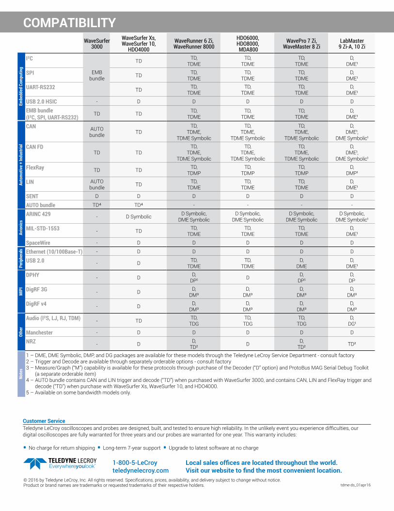
1 – DME, DME Symbolic, DMP, and DG packages are available for these models through the Teledyne LeCroy Service Department - consult factory2 – Trigger and Decode are available through separately orderable options - consult factory3 – Measure/Graph (“M”) capability is available for these protocols through purchase of the Decoder (“D” option) and ProtoBus MAG Serial Debug Toolkit
(a separate orderable item) 4 – AUTO bundle contains CAN and LIN trigger and decode (“TD”) when purchased with WaveSurfer 3000, and contains CAN, LIN and FlexRay trigger and
decode (“TD”) when purchase with WaveSurfer Xs, WaveSurfer 10, and HDO4000.5 – Available on some bandwidth models only.
Embe
dded
Com
putin
gAu
tom
otiv
e +
Indu
stria
lAv
ioni
csPe
riphe
rals
MIP
IOt
her
Note
s
Customer ServiceTeledyne LeCroy oscilloscopes and probes are designed, built, and tested to ensure high reliability. In the unlikely event you experience difficulties, our digital oscilloscopes are fully warranted for three years and our probes are warranted for one year. This warranty includes:
• No charge for return shipping • Long-term 7-year support • Upgrade to latest software at no charge
tdme-ds_01apr16© 2016 by Teledyne LeCroy, Inc. All rights reserved. Specifications, prices, availability, and delivery subject to change without notice. Product or brand names are trademarks or requested trademarks of their respective holders.
1-800-5-LeCroy teledynelecroy.com
Local sales offices are located throughout the world.Visit our website to find the most convenient location.