low-power wi-fi enabled electronic paper display …€¢ electronic shelf labels ... some...
TRANSCRIPT

WI-FINWP
CC 3200
ARMCortex M4
2.4 GHzANT
EPD Display panel
Switch (reset)Serial flash
EPD Boosterpack
1TIDUB20A–January 2016–Revised September 2016Submit Documentation Feedback
Copyright © 2016, Texas Instruments Incorporated
Low-Power Wi-Fi Enabled Electronic Paper Display (EPD)
TI DesignsLow-Power Wi-Fi Enabled Electronic Paper Display (EPD)
TI DesignsTI Designs provide the foundation that you needincluding methodology, testing and design files toquickly evaluate and customize the system. TI Designshelp you accelerate your time to market.
Design Resources
TIDC-CC3200_EPD_DesignTool Folder Containing DesignFiles
CC3200 Product Folder
ASK Our E2E Experts
Design Features• Low-Power, Battery Powered• Cloud Connectivity• Local Control• Supports 5 Display Sizes• Supports Custom Graphics• Broadcast Contents Option
Featured Applications• Electronic Shelf Labels• Name Tags• Indoor Signage• Wearables
An IMPORTANT NOTICE at the end of this TI reference design addresses authorized use, intellectual property matters and otherimportant disclaimers and information.

Key System Specifications www.ti.com
2 TIDUB20A–January 2016–Revised September 2016Submit Documentation Feedback
Copyright © 2016, Texas Instruments Incorporated
Low-Power Wi-Fi Enabled Electronic Paper Display (EPD)
1 Key System SpecificationsTable 1 shows the key system specifications.
Table 1. Key System Specifications
PARAMETER SPECIFICATION DETAILSOperating voltage 2.3 V to 3.6 V
Working environment Indoor environment. For higher temperature and humidity range,compensation has to be made when writing to the EPD
Average current Highly dependant on use-case See Section 5.3Peak current Achieved during power-ups CC3200 Datasheet
www.ti.com System Description
3TIDUB20A–January 2016–Revised September 2016Submit Documentation Feedback
Copyright © 2016, Texas Instruments Incorporated
Low-Power Wi-Fi Enabled Electronic Paper Display (EPD)
2 System Description
2.1 IntroductionThis design demonstrates the single-chip implementation of a wireless Electronic Paper Display (EPD)using Wi-Fi technology. Technologies that use EPD displays require low-power operation and a methodfor the user to update the display information. This design provides user control using remotemaintenance, an important service in the growing Industrial Internet of things (IoT) market. The designuses the low-power TI SimpleLink Wi-Fi CC3200 wireless MCU, allowing the user to work on two AAbatteries for several months, depending on the specific use-case. With an integrated micro-controller andWi-Fi network processor, this CC3200-based design is a single-chip solution for an EPD display withremote control, locally or over the internet using the MQTT protocol.
3 Design FeaturesThe low-power wireless EPD display allows the user to easily and wirelessly control the contents of any offive different EPD display panels, and demonstrates TI’s SimpleLink capabilities of ease of use and low-power. Using either an internal HTTP page embedded in the device, or any MQTT client, the user has theability to control the contents of the EPD display and configure many parameters. The parameters arethen saved and loaded on next power-up. The display accepts text and icons as custom icons, andgraphic files may be programmed into the device from a PC.
When remotely controlled, the user has the ability to update any number of EPD panels simultaneously,regardless of their physical location or size by giving them the same name. This use-case is crucial forsome electronic shelf label applications, where pricing labels need to be updated at several locations atonce, for example.
From a power perspective, this design utilizes one of EPD technology’s main advantages of consuming nopower between updates. In between updates, the Simplelink device is configured to remain connected,allowing for prompt response of the EPD panel, or intermittently connected at a configurable interval.Being connected to the configurable interval allows for an even lower power consumption and longerbattery life. CC3200’s Cortex M4 MCU directly drives the EPD display, fast and efficiently, allowing shorterupdate times compared to other implementations, contributing to the low power consumption of the entiresystem.
The display is comprised of the following parts:• A title bar– shows the current operating mode, the device name, and Wi-Fi® reception level.• An icon, typically 64×64 pixels– either a pre-loaded BMP, or an over-the-air sent graphics.• Title text– appears next to the icon, typically in a larger font size than the body text. Not available in
1.44" display layout.• Body text– appears at the bottom. Is typically more than one line long and automatically wraps.

2.7
2.6
2.0
1.9
1.44
Image
Image
Image
Image
Image
Information Bar
Title Text (21 chars)
Body text ± up to 2 lines (33 chars each)
Title Text (of 17 chars)
Body text ± 2 lines (of 28 chars each)
Title text 15 chars
Title Text (8 chars)
Body text ± 2 lines (17 chars)
Small text (16 chars)
Information Bar
Information Bar
Information Bar
Information Bar
Body text 24 chars
Design Features www.ti.com
4 TIDUB20A–January 2016–Revised September 2016Submit Documentation Feedback
Copyright © 2016, Texas Instruments Incorporated
Low-Power Wi-Fi Enabled Electronic Paper Display (EPD)
Figure 1 shows the different EPD layouts.
Figure 1. EPD Layout per Display Size

WI-FINWP
CC 3200
ARMCortex M4
2.4 GHzANT
EPD Display panel
Switch (reset)Serial flash
EPD Boosterpack
www.ti.com Block Diagram
5TIDUB20A–January 2016–Revised September 2016Submit Documentation Feedback
Copyright © 2016, Texas Instruments Incorporated
Low-Power Wi-Fi Enabled Electronic Paper Display (EPD)
4 Block DiagramFigure 2 shows a high level block diagram of the system. The hardware is comprised of the standardCC3200 LaunchPad™, the EPD BoosterPack™.
Figure 2. High Level System Block Diagram
4.1 Highlighted ProductsThis reference design features the CC3200. The SimpleLink Wi-Fi CC3200- wireless MCU integrates ahigh-performance Cortex-M4 MCU and peripherals. This design utilizes the CC3200-LAUNCHXL EVMthat contains the CC3200 reference design along with emulation and a BoosterPack connector. TheCC3200 MCU controls the EPD using an SPI interface. Figure 3 shows the CC3200–LAUNCHXL EVM.
Figure 3. CC3200–LAUNCHXL EVM

Internet MQTT Broker
System Design Theory www.ti.com
6 TIDUB20A–January 2016–Revised September 2016Submit Documentation Feedback
Copyright © 2016, Texas Instruments Incorporated
Low-Power Wi-Fi Enabled Electronic Paper Display (EPD)
5 System Design TheoryThis design introduces two ways of controlling the EPD panel–locally, and remotely.
Locally, the EPD panel is controlled by any connected device on the same network. Remotely, the EPDpanel is controlled by any internet connected device, anywhere in the world.
Controlling the EPD panel remotely is more power efficient, as the MQTT broker (server) buffers the datauntil it is polled by the SimpleLink device. Figure 4 shows the system design theory, case one–remotecontrol and Figure 5 shows the system design theory, case two–local control.
Figure 4. System Design Theory, Case 1–Remote Control
Figure 5. System Design Theory, Case 2–Local Control
www.ti.com System Design Theory
7TIDUB20A–January 2016–Revised September 2016Submit Documentation Feedback
Copyright © 2016, Texas Instruments Incorporated
Low-Power Wi-Fi Enabled Electronic Paper Display (EPD)
5.1 Hardware
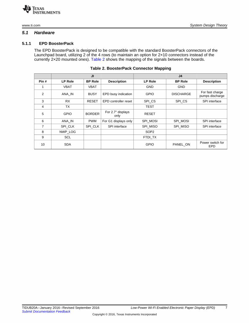
5.1.1 EPD BoosterPackThe EPD BoosterPack is designed to be compatible with the standard BoosterPack connectors of theLaunchpad board, utilizing 2 of the 4 rows (to maintain an option for 2×10 connectors instead of thecurrently 2×20 mounted ones). Table 2 shows the mapping of the signals between the boards.
Table 2. BoosterPack Connector Mapping
JI J4Pin # LP Role BP Role Description LP Role BP Role Description
1 VBAT VBAT GND GND
2 ANA_IN BUSY EPD busy indication GPIO DISCHARGE For fast chargepumps discharge
3 RX RESET EPD controller reset SPI_CS SPI_CS SPI interface4 TX TEST
5 GPIO BORDER For 2.7" displaysonly RESET
6 ANA_IN PWM For G1 displays only SPI_MOSI SPI_MOSI SPI interface7 SPI_CLK SPI_CLK SPI interface SPI_MISO SPI_MISO SPI interface8 NWP_LOG SOP29 SCL FTDI_TX
10 SDA GPIO PANEL_ON Power switch forEPD

System Design Theory www.ti.com
8 TIDUB20A–January 2016–Revised September 2016Submit Documentation Feedback
Copyright © 2016, Texas Instruments Incorporated
Low-Power Wi-Fi Enabled Electronic Paper Display (EPD)
5.1.2 EPD PanelsThe design supports all small display panels from pervasive displays, which are:• 1.44"• 1.9"• 2.0"• 2.6"• 2.7"
The supported panel type is the Aurora Mb (V231) G2 by pervasive displays. There is backwards supportfor Vizplex (V230) or G1 panels using software compilation flags, but it is strongly recommended to onlyuse V231 G2 panels.
EPD panels are sensitive to temperature. The lower the temperature is, the more time is required to drivethe image to get similar optical results. This design is aimed for indoor applications, and it is assumed thatthe EPD panel is operating at room temperature.
In case the temperature drops below room temperature to a point in which there is visible opticaldegradation, the configurable display quality can be set to optimal quality to compensate for it. Thesoftware contains a hook for user temperature sensing function. It is currently statically set for 25 degrees.If required, a function that gets the temperature from the Launchpad’s onboard sensor may beimplemented.
NOTE: Compensations for lower temperatures defeat the purpose of using partial update to shortenupdate cycles.

Start
Start SimpleLink
Load Configuration
EPD Initialization
WLAN connected?
Start Provisioning
Provisioning complete?
Initialize MQTT library
Set Power Policy
MainFSM
Yes
Yes
No
www.ti.com System Design Theory
9TIDUB20A–January 2016–Revised September 2016Submit Documentation Feedback
Copyright © 2016, Texas Instruments Incorporated
Low-Power Wi-Fi Enabled Electronic Paper Display (EPD)
5.2 SoftwareThe software supplied with this design is based on the SimpleLink CC3200 SDK MQTT example,combined with the pervasive display driver. The software works in a FreeRTOS environment, and has twothreads. One for the SimpleLink driver, and the other for the application. Figure 6 shows how the softwareflow is divided into two main steps–initialization and the main state machine, and Figure 7 shows thesoftware main state machine flow.
Figure 6. Software Initialization Flow

MainFSM
Set working mode
Mode changed?
Working mode?
Wait for event1 in low power mode
Handle event and update EPD
Event1 pending?Enter Hibernate
Handle event,update EPD,
clear message if required
Hibernate
OtherYes
No
Yes
No
System Design Theory www.ti.com
10 TIDUB20A–January 2016–Revised September 2016Submit Documentation Feedback
Copyright © 2016, Texas Instruments Incorporated
Low-Power Wi-Fi Enabled Electronic Paper Display (EPD)
Figure 7. Software Main State Machine Flow
5.2.1 ProvisioningWhen the system boots (whether from power off or from a hibernate cycle), it will attempt to connect to aknown AP. If it fails to find one in a predefined amount of time, the provisioning procedure is activated.
The purpose of this procedure is to connect the system to a new AP and add a profile for later use. Whenthe provisioning procedure starts, a message will be displayed on the screen. Use TI’s provisioningapplication for iPhone or Android to send the AP credentials to the device.
Once provisioning is complete, a message will be displayed on the screen, and the phone’s provisioningapplication directs you to the device’s web page. In case provisioning fails or times out, a message isdisplayed, and the device goes into hibernation to conserve current. The duration of the hibernation is thepre-configured interval, or default value in case it was never configured.

www.ti.com System Design Theory
11TIDUB20A–January 2016–Revised September 2016Submit Documentation Feedback
Copyright © 2016, Texas Instruments Incorporated
Low-Power Wi-Fi Enabled Electronic Paper Display (EPD)
5.2.2 HTTP User InterfaceThe HTTP page is designed to reflect the currently displayed image on the EPD panel. This is true evenwhen controlled by more than one simultaneously, and updates from one device will propagate to otherconnected controllers.
The main page allows the user to update the text fields (title and text) and select an icon from a drop-down list. Applying the changes will cause the sign to update.• Click on the icon sign and load any image if a custom icon is required.
NOTE: The image will be scaled down to 64×64 pixels and is black and white. TI recommends touse an image with the correct size and color pallet to begin with.
• Select the icon number to save the image to the sign, or select volatile in order not to save it when acustom image is uploaded.Figure 8 shows the HTTP user interface window.
Figure 8. HTTP User Interface
• Press the three dots icon on the top right corner to open the configuration panel. There you can switchbetween modes, display types, display qualities, and configure timer intervals. These changes may besaved to the filesystem if required.

System Design Theory www.ti.com
12 TIDUB20A–January 2016–Revised September 2016Submit Documentation Feedback
Copyright © 2016, Texas Instruments Incorporated
Low-Power Wi-Fi Enabled Electronic Paper Display (EPD)
5.3 PowerThe system is designed to work off 2×AA alkaline batteries, allowing a voltage range of approximately 3-Vdown to approximately 2.3-V, which is the lowest voltage allowed for the EPD. The system is capable ofoperating on voltages up to 3.6-V. The EPD driving circuitry is designed to disconnect the EPD (using aFET) whenever it is not in use, and is controlled by the PANEL_ON signal.
The current measurement in this episode are done in two parts (CC3200 and EPD Boosterpack) and arethen superimposed.
The detailed analysis of power consumption per mode and element is described in the followingsubsections. For the lowest power consumption, the intermittently connected profile should be used. Withthis profile, the longest battery life is achieved.
Table 3 lists the projected battery lifetime for 2xAA alkaline batteries on a 2.7” display (worst-case), forvarious polling intervals and the percentage of new content available per polling cycle. The breakdown forthese figures is detailed in the following chapters.
Table 3. Projected Battery Lifetime for Various Scenarios
LIFETIME IN YEARSNew Content
Available Every Update Every 2ndUpdate Every 4th Update Every 10th Update
Polling every10 minutes 0.42 0.52 0.57 0.63
Polling every15 minutes 0.63 0.78 0.89 0.98
Polling every30 minutes 1.23 1.52 1.73 1.94
Polling every 1hour 2.36 2.89 3.26 3.53
Polling every 4hours 7.5 Over 10 Over 10 Over 10
Polling twicedaily Over 10 Over 10 Over 10 Over 10
Polling oncedaily Over 10 Over 10 Over 10 Over 10
For example, if the EPD panel is polling the MQTT broker once every 30 minutes. On average, a newmessage arrives every 2 hours, and the projected battery lifetime would be about 1.7 years.
With a smart scheduler, a combination of polling intervals may be configured. For example, updating every15 minutes during working ours, and no updates for the rest of the time, with new data coming everysecond wake-up, will lead to 1.5 years, while still allowing a reasonably short response time.
5.3.1 WLAN Current ConsumptionThe design incorporates three main working modes, each with its own current consumption profile. Thefollowing sections describe these modes in depth.
NOTE: All figures given were measured in a moderately congested open-air environment, on atypical home AP with WPA2 personal security. The current consumption may vary greatly inboth directions based on AP type, security type, distance from the AP, air congestion, trafficfrom peer clients, and more. Please treat these numbers as an estimate.
www.ti.com System Design Theory
13TIDUB20A–January 2016–Revised September 2016Submit Documentation Feedback
Copyright © 2016, Texas Instruments Incorporated
Low-Power Wi-Fi Enabled Electronic Paper Display (EPD)
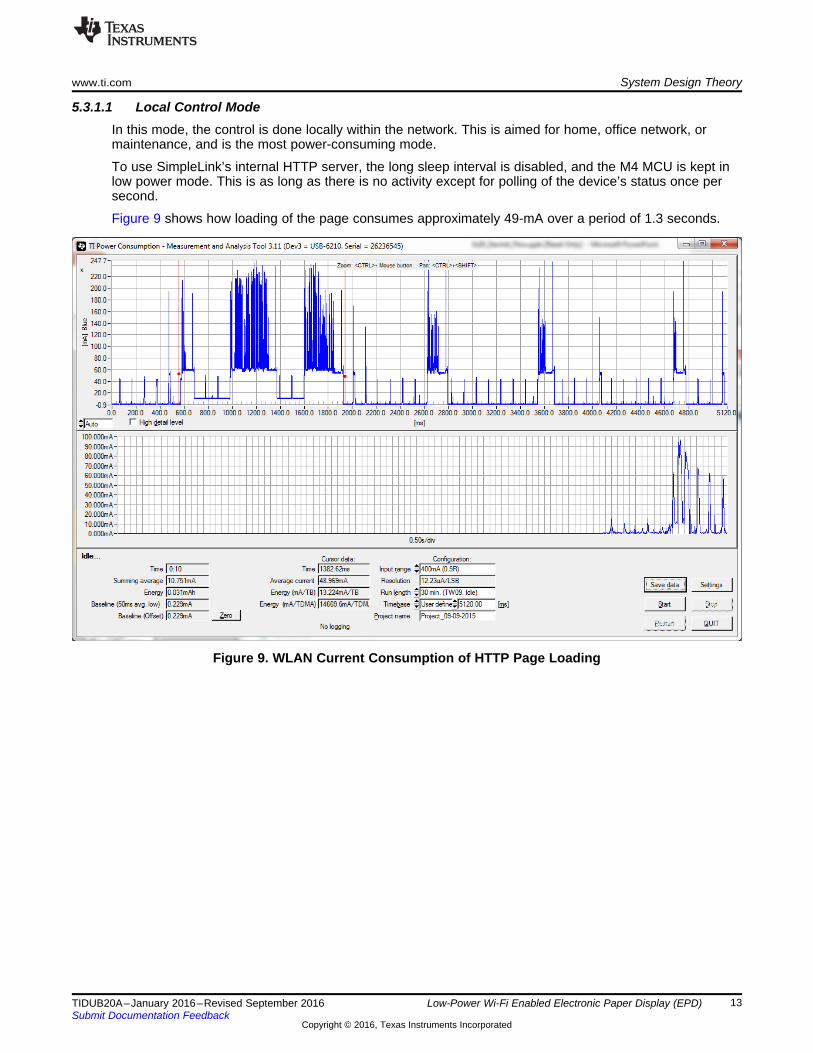
5.3.1.1 Local Control ModeIn this mode, the control is done locally within the network. This is aimed for home, office network, ormaintenance, and is the most power-consuming mode.
To use SimpleLink’s internal HTTP server, the long sleep interval is disabled, and the M4 MCU is kept inlow power mode. This is as long as there is no activity except for polling of the device’s status once persecond.
Figure 9 shows how loading of the page consumes approximately 49-mA over a period of 1.3 seconds.
Figure 9. WLAN Current Consumption of HTTP Page Loading
System Design Theory www.ti.com
14 TIDUB20A–January 2016–Revised September 2016Submit Documentation Feedback
Copyright © 2016, Texas Instruments Incorporated
Low-Power Wi-Fi Enabled Electronic Paper Display (EPD)
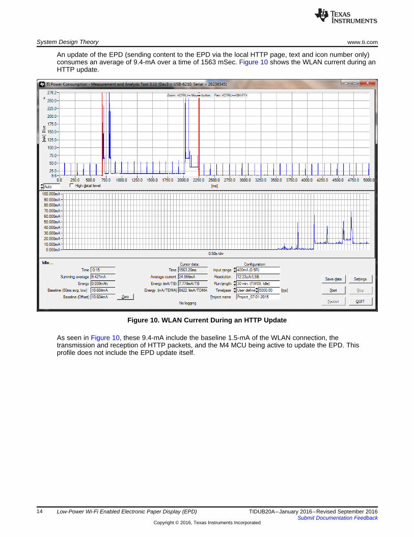
An update of the EPD (sending content to the EPD via the local HTTP page, text and icon number only)consumes an average of 9.4-mA over a time of 1563 mSec. Figure 10 shows the WLAN current during anHTTP update.
Figure 10. WLAN Current During an HTTP Update
As seen in Figure 10, these 9.4-mA include the baseline 1.5-mA of the WLAN connection, thetransmission and reception of HTTP packets, and the M4 MCU being active to update the EPD. Thisprofile does not include the EPD update itself.

www.ti.com System Design Theory
15TIDUB20A–January 2016–Revised September 2016Submit Documentation Feedback
Copyright © 2016, Texas Instruments Incorporated
Low-Power Wi-Fi Enabled Electronic Paper Display (EPD)
Once the page has been loaded, the browser will poll on the device for any changes to the sign’scontents, issued from other devices. Polling occurs once per second and helps keep all browsers in syncwith the sign’s actual contents. Polling consists of an RX/TX cycle once per second, as well as keepingthe M4 MCU active for approximately 100 mSec. The average current in this mode is approximately 12.4-mA for one polling browser. Figure 11 shows the WLAN during HTTP idle polling.
Figure 11. WLAN During HTTP Idle Polling

System Design Theory www.ti.com
16 TIDUB20A–January 2016–Revised September 2016Submit Documentation Feedback
Copyright © 2016, Texas Instruments Incorporated
Low-Power Wi-Fi Enabled Electronic Paper Display (EPD)
5.3.1.2 Remote Control Mode or Timer ModeIn this mode, the LSI (Long Sleep Interval) is enabled at an interval of 500-mSec to reduce currentconsumption while connected to the remote MQTT broker. The HTTP server is disabled in this mode.
While connecting to the remote broker, a keepalive exchange is done every 120 seconds. Averaging thecurrent consumption over 10 minutes shows an average current consumption of slightly less than 1 mA.
An incoming update event from the MQTT broker consumes around 19-mA over a period of 1600 mSec.The update event includes the exchange with the MQTT broker, and the M4 up time for updating the EPDdisplay, but does not include the update of the EPD itself, or the submission of the status updatemessage. Figure 12 shows a single update after 10 minutes of idle connection, showing a summingaverage of 1.03mA, which gives an estimate for this type of case.
Figure 12. WLAN Current During an MQTT Update

www.ti.com System Design Theory
17TIDUB20A–January 2016–Revised September 2016Submit Documentation Feedback
Copyright © 2016, Texas Instruments Incorporated
Low-Power Wi-Fi Enabled Electronic Paper Display (EPD)
5.3.1.3 Intermittently Connected ModeThis mode consumes the least amount of current. The SimpleLink device remains in hibernate modebetween updates for the duration of the configured interval. During this period the EPD is turned off,consumes a negligible amount of current. The WLAN subsystem is also turned off, and the applicationMCU subsystem is suspended with a timer set for waking it up. The entire system consumes less than 10uA in this mode (CC3200 + EPD BP). The exact figure varies according to temperature and process, referto the datasheet for details.
For each hibernate cycle, the MCU wakes up, detects it is out of hibernate mode, begins the WLAN, andwaits in power-saving mode until the WLAN is connected to the access point. The MCU then connects tothe MQTT broker and waits in power-saving mode for 10 seconds to see if a message is pending. If thereare no pending messages, the MCU will disconnect and re-enter hibernate. If there is a pending message,it will be grabbed and the screen will be updated with the new message. According to the settings, themessage may be acknowledged (clear retained MQTT message).. According to the settings, the messagemay be acknowledged (clear retained MQTT message). Unacknowledged messages are useful forcontrolling several clients simultaneously.
If a message was received, a status update will be sent to signal to all sending devices that the displaywas updated. All current measurements in this design include the acknowledging of the messages (worst-case scenario). Figure 13 shows intermittently connected–polling without an update.
Figure 13. Intermittently Connected–Polling Without an Update
A cycle without an update takes slightly over 10 seconds (as the timer for re-entering hibernate is set for10 seconds, plus the initialization delay before that timer is set). For such cycles, the EPD panel remainsoff. Table 4 lists the intermittently connected cycles without an update.
Table 4. Intermittently Connected Cycles Without an Update
EPD TYPE TIME(S) AVG. CURRENT(mA) Q(mC)
2.7” 10.5 21.7 228
Figure 14 shows the intermittently connected–polling and updating a 2.7” panel.
Figure 14. Intermittently Connected–Polling and Updating a 2.7” Panel

System Design Theory www.ti.com
18 TIDUB20A–January 2016–Revised September 2016Submit Documentation Feedback
Copyright © 2016, Texas Instruments Incorporated
Low-Power Wi-Fi Enabled Electronic Paper Display (EPD)
For cycles with an update, the extra current is derived from receiving the message, acknowledging it(when configured to), and sending a status update. The cycles' current figures do not vary much accordingto display size–only the update time variance between the panel types. The worst case (2.7” panels)measurements are taken for the rest of the current consumption measurements. Table 5 lists theintermittently connected cycles with a 2.7” panel update.
Table 5. Intermittently Connected Cycles With a 2.7” Panel Update
EPD TYPE TIME(S) AVG. CURRENT(mA) Q(mC)
2.7” 10.5 35.5 372.8
www.ti.com System Design Theory
19TIDUB20A–January 2016–Revised September 2016Submit Documentation Feedback
Copyright © 2016, Texas Instruments Incorporated
Low-Power Wi-Fi Enabled Electronic Paper Display (EPD)
5.3.2 EPD Current ConsumptionIn between updates, the supply rail to the EPD panel is cut by a MOSFET, and consumes a very lowamount of power.
To minimize current consumption during updates, a partial update scheme is used, which only changespixels that require change instead of flashing the entire screen (full update). This allows for a shorterupdate time, meaning less current wasted by the EPD, as well as by the M4 MCU. The M4 MCU is able tofinish the update quicker and go back into power saving mode. The downside of this approach is ghostingof the previous image. The amount of ghosting is derived from the amount of time the update takes. Thisis user configurable, given in three steps (optimized for power, optimized for quality, or balanced). Foreach update, the user may force a full refresh to clean previous ghosting when required.
Full refresh is forced during the system initially (since the previous image is not kept), and in intermittentlyconnected mode because the memory is not retained and the previous image is not available forcomparison. Using the NVMEM to keep the previous image would save some current, but the system’slifetime would shorten due to frequent writes to the serial flash.
5.3.2.1 Stage Time CalculationsStage time is defined as the time it takes to drive the required image. For each iteration, multiple framedrives are required (each one requires a certain amount of frame time). During the frame time, the inkparticles are moved toward their destination (black to white, or vice versa). The frame time depends on thedisplay size and the driving MCU.
Pervasive displays recommends driving at least five frames per stage to achieve an acceptable result. Thehard coded stage times in the software are set for power optimized values, balanced values and imagequality optimized values.
The stage times for full updates are fixed to the values defined by pervasive displays, which are 630-mSecfor 2.7” and 2.6” displays, and 480-mSec for the rest of the displays.
For a partial update, the stage time is kept flexible in this design to allow flexibility of display quality v.current consumption. Stage time was measured per display size on CC3200 during partial updates, anddifferent stage times were tried to achieve the stage time per display quality setting and display size. Theaddition in current per display profile is described in Section 5.2.2.
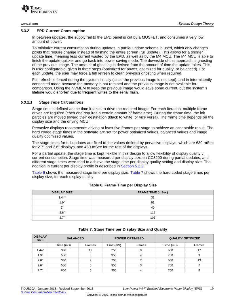
Table 6 shows the measured stage time per display size. Table 7 shows the hard coded stage times perdisplay size, for each display quality.
Table 6. Frame Time per Display Size
DISPLAY SIZE FRAME TIME (mSec)1.44” 311.9” 912” 40
2.6” 1172.7” 103
Table 7. Stage Time per Display Size and Quality
DISPLAYSIZE BALANCED POWER OPTIMIZED QUALITY OPTIMIZED
Time (mS) Frames Time (mS) Frames Time (mS) Frames1.44” 350 12 250 9 500 171.9” 500 6 350 4 750 92.0” 350 9 250 7 500 132.6” 500 5 350 3 750 72.7” 600 6 350 4 750 8

System Design Theory www.ti.com
20 TIDUB20A–January 2016–Revised September 2016Submit Documentation Feedback
Copyright © 2016, Texas Instruments Incorporated
Low-Power Wi-Fi Enabled Electronic Paper Display (EPD)
5.3.2.2 EPD Current ConsumptionEPD boosterpack measurements in this section is completed separately from the CC3200 LaunchPad.Figure 15 shows the 2.7” full update current consumption.
Figure 15. 2.7” Full Update Current Consumption
Table 8 lists the full update current consumption per display type.
Table 8. Full Update Current Consumption per Display Type
EPD TYPE UPDATE TIME(S) AVG. CURRENT(mA) Q(mC)
2.7” 3.58 1.99 7.122.6” 3.47 2.06 7.142.0” 2.75 2.02 5.551.9” 2.71 2.05 5.551.44” 2.7 2.11 5.69
Table 9 lists the partial update current consumption per display type and display quality.
Table 9. Partial Update Current Consumption per Display Type and Display Quality
POWER AND QUALITYOPTIMIZED OPTIMIZED for DISPLAY QUALITY POWER OPTIMIZED
Type TimeAvg
Current
Q(mC) Time Avg Current Q(mC) Time Avg Current Q(mC)
2.7" 1.43 2.1 3.003 1.63 2 3.26 1.22 2.25 2.7452.6" 1.4 2.08 2.912 1.64 1.96 3.2144 1.14 2.32 2.64482.0" 1.15 2.2 2.53 1.3 2.04 2.652 1.06 2.3 2.4381.9" 1.36 2.08 2.8288 1.62 1.94 3.1428 1.16 2.27 2.63321.44” 1.14 2.3 2.622 1.3 2.12 2.756 1.03 2.4 2.472

www.ti.com Getting Started Hardware
21TIDUB20A–January 2016–Revised September 2016Submit Documentation Feedback
Copyright © 2016, Texas Instruments Incorporated
Low-Power Wi-Fi Enabled Electronic Paper Display (EPD)
6 Getting Started Hardware
6.1 HardwareTo get started, you are required to have:• A CC3200 LaunchPad• An EPD BoosterPack• One of 5 EPD displays by Pervasive Displays (1.44", 1.9", 2.0", 2,6", or 2.7")
6.2 Power OptimizationsThe EPD BoosterPack is designed to be power optimized, thus, no further optimization is required.
The CC3200 Launchpad requires an ECO to make it power optimized. This is not mandatory for runningthe application, just for being able to achieve the power figures described here.
The required changes (for LaunchPad Rev 4.1) are:• Remove R129, R3 and R20• Remove J12 jumper• Disconnect the USB cable from the LaunchPad• Connect the battery positive to J12 pin 1• Connect the battery negative to J20 pin 3• Remove R5• Wire from R5 (the side near the LDO) to Battery +• Wire J13 (bottom side, near the CC3200 chip) to Battery +• Remove J6, J7, J8, J9, J10, J11, J2, and J3 jumpers
NOTE: In this configuration, LEDs will not be functional and programming will not be possible. Thereset switch will not work either. This mode is for running the application once itspreprogrammed into the serial flash, and not for debugging.
6.3 Using the Pervasive Displays BoosterPackThis design was made to work with the EPD BoosterPack. If such a board is not available, using thePervasive Displays BoosterPack is possible, but some of the features of this design will not be functional.
When using the Pervasive Displays BoosterPack, low-power figures are not achieved, as the BoosterPackis not optimized for power. In addition, remote modes (remote active and remote low power) may notfunction properly, and they are redundant because low power cannot be achieved in this configuration. Touse remote connection, select "always connected" mode instead.
To use the Pervasive Displays BoosterPack, make the following changes to the design software:1. Undefine #TI_EPD_BOOSTERPACK and define #PERVASIVE_DISPLAYS_BOOSTERPACK in
\EPD_Driver\conf_EPD.h and in \EPD_Driver\Pervasive_Displays_Small_EPD\EPD_hardware.c2. In \EPD_Driver\Pervasive_Displays_Small_EPD\EPD_hardware.h, change the #define EPD_CS_GPIO
from 40 to 283. In \EPD_Driver\Pervasive_Displays_Small_EPD\EPD_hardware.c, empty the functions
EPD_flash_cs_high and EPD_flash_cs_low (make these functions empty). The design does not usethe Pervasive Displays BoosterPack's onboard serial flash to store intermediate images.
In addition, on the LaunchPad, remove jumpers J6, J7, J15 (SoP2), J2, and J3.
Both version 1 and 2 of the Pervasive Displays BoosterPacks may be used using this method.

Getting Started Firmware www.ti.com
22 TIDUB20A–January 2016–Revised September 2016Submit Documentation Feedback
Copyright © 2016, Texas Instruments Incorporated
Low-Power Wi-Fi Enabled Electronic Paper Display (EPD)
7 Getting Started Firmware
7.1 User FilesThe design accepts custom user graphic files. All graphic files must be in Bitmap (.BMP) format, 1 bit(monochrome).
Two user graphic files are supported:• Icons– Load 1 to 10 icons to the design. TI recommends the size of the icons are 64×64 pixels.• Splash screen– This image is displayed when the system initializes from power off, and is removed
once it is ready to receive messages. Any resolution up to the limit of the EPD panel is supported, withone restriction. The X aspect must be 32-bits aligned (for example, 32xY, 64xY, 96xY...). This is due tothe BMP's format's padding. A small software change may enable 8-bit alignment.
If a missing icon file is requested by the user, a broken image icon (hard coded) will be displayed instead.If a splash screen is missing, a blank image will be displayed instead. Even if no user graphic file isloaded, the application will still run normally. TI recommends to program at least a couple of custom iconsto get the best user experience.
Another user file is display.txt. This file contains the default display size connected to the system. Thecontents of this file is a single digit ASCII number of 0 through 4. If this file does not exist, the software willdefault to 2.7”. This value can be overridden and saved to the file system through the HTTP interface. Theuser may also switch display sizes while the system is in power-saving mode (between screen updates),since the EPD panel is shut down at those periods. Once the display has been replaced and reconfiguredvia the HTTP interface, the new display will refresh automatically.
Table 10 lists the display.txt values per display size.
Table 10. Display.txt Values per Display Size
DISPLAY TYPE DISPLAY.TXT VALUE1.44” 02.0” 12.7” 21.9” 32.6” 4
Warning: Defining a wrong display size will result in images appearing incorrectly.

www.ti.com Getting Started Firmware
23TIDUB20A–January 2016–Revised September 2016Submit Documentation Feedback
Copyright © 2016, Texas Instruments Incorporated
Low-Power Wi-Fi Enabled Electronic Paper Display (EPD)
7.2 UniflashThe user files must be added to the existing Uniflash bundle. Without programming the Uniflashbundle, the application will not work.
The Uniflash bundle includes the constant icons, application binary, display.txt file, HTTP page and itscollaterals, and optional user graphics files– icons and splash screens.
To use, have Uniflash installed on your PC and run it. Load the .ucf file located at the root of the Uniflashfiles folder. Figure 16 shows the Uniflash folder example.
Figure 16. Uniflash Folder Example
1. Determine the COM port number assigned to the LaunchPad by your PC once Uniflash has loaded.2. Refer to 7.3.1 for details (user logs are output on the same COM port).3. Make sure the SOP2 jumper on the LaunchPad is assembled to enable programming.4. Update the COM port field with the correct COM port number if required.5. If this is the first usage of the LaunchPad, format the serial flash by pressing the format button
(approve the default 1-MB serial flash value).6. Press the reset button on the LaunchPad when prompted.7. Remove the SOP2 jimper form the LaunchPad once all programming is completed.8. Press the reset button.9. The software begins to run.10. The user is greeted by the splash screen graphics if one was programmed.
Getting Started Firmware www.ti.com
24 TIDUB20A–January 2016–Revised September 2016Submit Documentation Feedback
Copyright © 2016, Texas Instruments Incorporated
Low-Power Wi-Fi Enabled Electronic Paper Display (EPD)
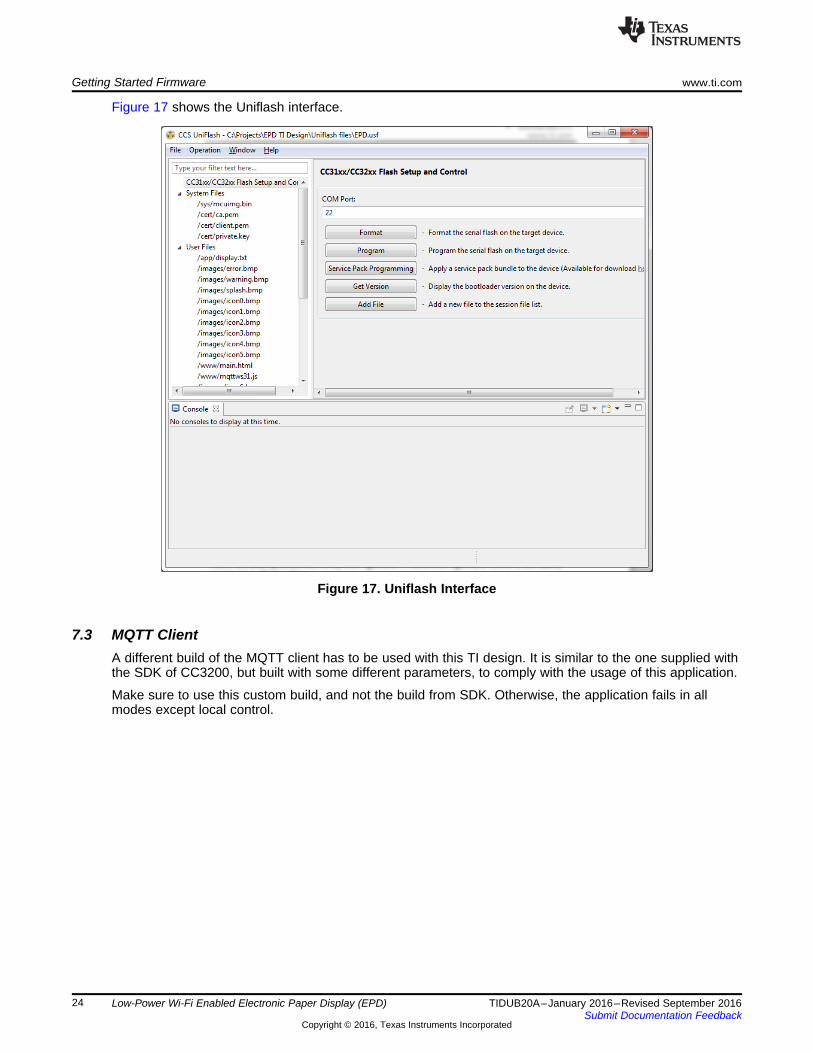
Figure 17 shows the Uniflash interface.
Figure 17. Uniflash Interface
7.3 MQTT ClientA different build of the MQTT client has to be used with this TI design. It is similar to the one supplied withthe SDK of CC3200, but built with some different parameters, to comply with the usage of this application.
Make sure to use this custom build, and not the build from SDK. Otherwise, the application fails in allmodes except local control.

www.ti.com Getting Started Firmware
25TIDUB20A–January 2016–Revised September 2016Submit Documentation Feedback
Copyright © 2016, Texas Instruments Incorporated
Low-Power Wi-Fi Enabled Electronic Paper Display (EPD)
7.4 SoftwareAssuming all required information is present in the SimpleLink’s filesystem (including application binary,display size) upon power-up. The EPD panel displays either the splash screen or clear the screen if thesplash screen graphics is not present. Then, the embedded network processor attempts to connect to apre-configured AP. If none is configured, or the AP is not found, the provisioning procedure starts.
NOTE: In case provisioning fails for any reason (such as time out), the application will enter anindefinite hibernate state to conserve power. A message will be displayed on the EPD toinstruct the user to reset the device to re-attempt provisioning
Once AP connection is established, the MCU software enters one of the three supported modes. For eachmode, an indication icon is displayed on the top left hand side. The reception indicator is located on thetop right side, and the panel’s URN (or name) is displayed in the middle. Table 11 lists the displayedicons' description.
Table 11. Displayed Icons' Description
ICON DESCRIPTION
Disconnected from the AP. Provisioning may be required.
Local control mode. Control the EPD panel using SimpleLink’s internal HTTP server.Fastest response time, highest current consumption. Internet connection is not required
in this mode.
Connected to remote MQTT broker. Fast response time, higher current consumption.
Temporarily always connected. Once the user-configurable timer expires, mode willswitch to Intermittently connected. While in this mode, attributes are the same as
always connected.Intermittently connected. Display will update at configured intervals. This mode
consumes the least amount of power, but response time is limited to the configuredinterval time.
Excellent reception (above -45 dB)
Good reception (between -45 dB and 60 dB)
Average reception (between -60 dB and 80 dB)
Poor reception (Below -80 dB)

Test Setup www.ti.com
26 TIDUB20A–January 2016–Revised September 2016Submit Documentation Feedback
Copyright © 2016, Texas Instruments Incorporated
Low-Power Wi-Fi Enabled Electronic Paper Display (EPD)
8 Test SetupCurrent measurements in this design were completed in two phases:1. Measuring CC3200 current2. Measuring the EPD panel's current
The total current consumption is the superposition of the two.
To measure the CC3200 current, a LaunchPad board is used. A current meter is connected instead ofjumper 12. This method isolates the CC3200 (and its serial flash) current consumption from the rest of theboard. Figure 18 shows the measuring current on the CC3200 LaunchPad.
Figure 18. Measuring Current on the CC3200 LaunchPad

www.ti.com Test Data
27TIDUB20A–January 2016–Revised September 2016Submit Documentation Feedback
Copyright © 2016, Texas Instruments Incorporated
Low-Power Wi-Fi Enabled Electronic Paper Display (EPD)
For the EPD BoosterPack, a current meter is connected between the LaunchPad's P1.1 (VCC to theBoosterPack) and its counterpart on the BoosterPack. Thus, measuring all current flow to theBoosterPack.
9 Test Data
9.1 EPD Current ConsumptionEPD current measurements and analyses are described in Section 5.3.2.
9.2 WLAN Current ConsumptionWLAN current measurements and analyses are described in Section 5.3.1.
Design Files www.ti.com
28 TIDUB20A–January 2016–Revised September 2016Submit Documentation Feedback
Copyright © 2016, Texas Instruments Incorporated
Low-Power Wi-Fi Enabled Electronic Paper Display (EPD)
10 Design Files
10.1 SchematicsTo download the schematics for each board, see the design files at http://www.ti.com/tool/TIDC-CC3200_EPD_DESIGN.
shows the EPD BoosterPack Schematic.
10.2 Bill of MaterialsTo download the bill of materials (BOM), see the design files at http://www.ti.com/tool/TIDC-CC3200_EPD_DESIGN.
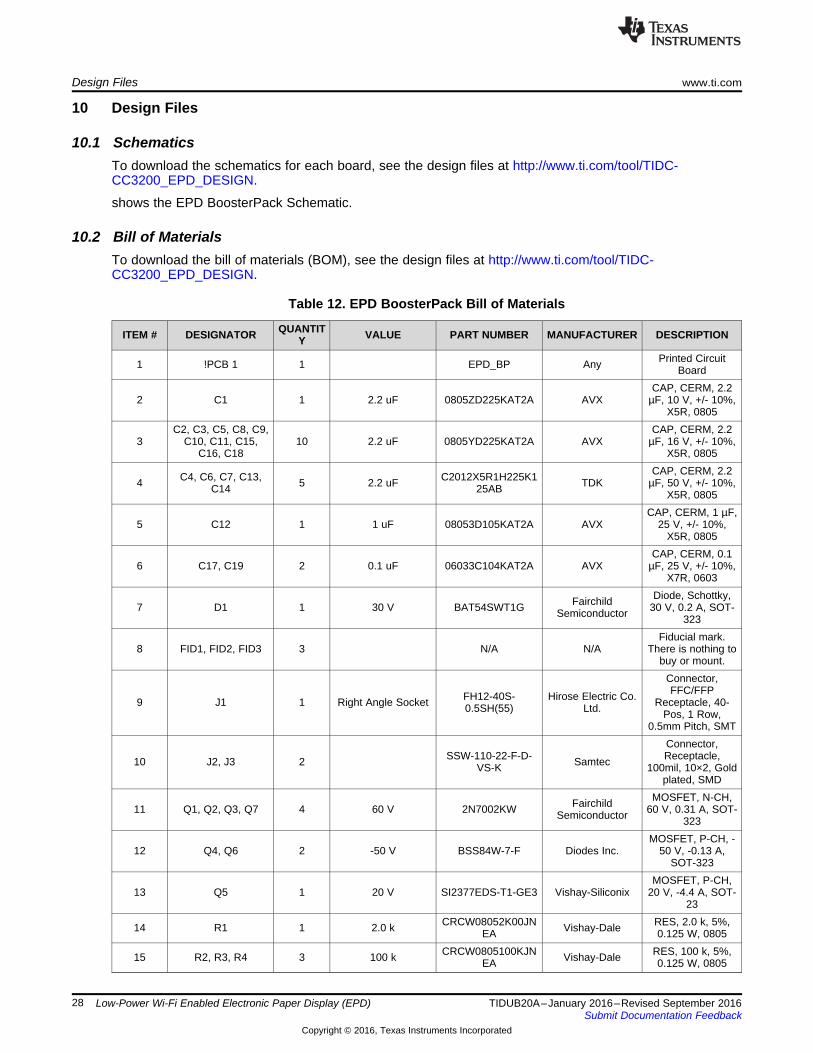
Table 12. EPD BoosterPack Bill of Materials
ITEM # DESIGNATOR QUANTITY VALUE PART NUMBER MANUFACTURER DESCRIPTION
1 !PCB 1 1 EPD_BP Any Printed CircuitBoard
2 C1 1 2.2 uF 0805ZD225KAT2A AVXCAP, CERM, 2.2
µF, 10 V, +/- 10%,X5R, 0805
3C2, C3, C5, C8, C9,
C10, C11, C15,C16, C18
10 2.2 uF 0805YD225KAT2A AVXCAP, CERM, 2.2
µF, 16 V, +/- 10%,X5R, 0805
4 C4, C6, C7, C13,C14 5 2.2 uF C2012X5R1H225K1
25AB TDKCAP, CERM, 2.2
µF, 50 V, +/- 10%,X5R, 0805
5 C12 1 1 uF 08053D105KAT2A AVXCAP, CERM, 1 µF,
25 V, +/- 10%,X5R, 0805
6 C17, C19 2 0.1 uF 06033C104KAT2A AVXCAP, CERM, 0.1
µF, 25 V, +/- 10%,X7R, 0603
7 D1 1 30 V BAT54SWT1G FairchildSemiconductor
Diode, Schottky,30 V, 0.2 A, SOT-
323
8 FID1, FID2, FID3 3 N/A N/AFiducial mark.
There is nothing tobuy or mount.
9 J1 1 Right Angle Socket FH12-40S-0.5SH(55)
Hirose Electric Co.Ltd.
Connector,FFC/FFP
Receptacle, 40-Pos, 1 Row,
0.5mm Pitch, SMT
10 J2, J3 2 SSW-110-22-F-D-VS-K Samtec
Connector,Receptacle,
100mil, 10×2, Goldplated, SMD
11 Q1, Q2, Q3, Q7 4 60 V 2N7002KW FairchildSemiconductor
MOSFET, N-CH,60 V, 0.31 A, SOT-
323
12 Q4, Q6 2 -50 V BSS84W-7-F Diodes Inc.MOSFET, P-CH, -
50 V, -0.13 A,SOT-323
13 Q5 1 20 V SI2377EDS-T1-GE3 Vishay-SiliconixMOSFET, P-CH,
20 V, -4.4 A, SOT-23
14 R1 1 2.0 k CRCW08052K00JNEA Vishay-Dale RES, 2.0 k, 5%,
0.125 W, 0805
15 R2, R3, R4 3 100 k CRCW0805100KJNEA Vishay-Dale RES, 100 k, 5%,
0.125 W, 0805
www.ti.com Design Files
29TIDUB20A–January 2016–Revised September 2016Submit Documentation Feedback
Copyright © 2016, Texas Instruments Incorporated
Low-Power Wi-Fi Enabled Electronic Paper Display (EPD)
Table 12. EPD BoosterPack Bill of Materials (continued)
ITEM # DESIGNATOR QUANTITY VALUE PART NUMBER MANUFACTURER DESCRIPTION
16 R5 1 33 k CRCW080533K0JNEA Vishay-Dale RES, 33 k, 5%,
0.125 W, 0805
10.3 PCB Layout RecommendationsThere is no special requirement for layout or routing. The form factor of the board was designed to matchthat of the LaunchPad beneath it, and the flat-cable connector was placed so that all display sizes willhave a mechanical support from the bare-PCB. Mechanical support is also the reason SMT connectorswere used.
10.3.1 Layout PrintsTo download the layout prints for each board. see the design files at http://www.ti.com/tool/TIDC-CC3200_EPD_Design.
10.4 Altium ProjectTo download the Altium project files, see the design files at http://www.ti.com/tool/TIDC-CC3200_EPD_Design.
10.5 Assembly DrawingsTo download the assembly drawings for each board, see the design files at http://www/ti.com/tool/TIDC-CC3200_EPD_Design.
10.6 Software FilesTo download the software files, see the design files at http://www.ti.com/tool/TIDC-CC3200_EPD_DESIGN.
11 TerminologyWLAN: Wirelss LAN
EPD: Electrophoretic Display
AP: Access Point

About the Author www.ti.com
30 TIDUB20A–January 2016–Revised September 2016Submit Documentation Feedback
Copyright © 2016, Texas Instruments Incorporated
Low-Power Wi-Fi Enabled Electronic Paper Display (EPD)
12 About the AuthorASAF CARMELI is a systems engineer at Texas Instruments where he defines hardware modules andsoftware flows for the SimpleLink devices. Asaf brings to this role 10 years in system engineering.

www.ti.com Revision History
31TIDUB20A–January 2016–Revised September 2016Submit Documentation Feedback
Copyright © 2016, Texas Instruments Incorporated
Revision History
Revision HistoryNOTE: Page numbers for previous revisions may differ from page numbers in the current version.
Changes from Original (January 2016) to A Revision .................................................................................................... Page
• Updated title to Low-Power Wi-Fi Enabled Electronic Paper Display (EPD). ..................................................... 1• Updated Introduction section............................................................................................................. 3• Added Using the Pervasive Displays BoosterPack section. ....................................................................... 21

IMPORTANT NOTICE FOR TI REFERENCE DESIGNS
Texas Instruments Incorporated (‘TI”) reference designs are solely intended to assist designers (“Designer(s)”) who are developing systemsthat incorporate TI products. TI has not conducted any testing other than that specifically described in the published documentation for aparticular reference design.TI’s provision of reference designs and any other technical, applications or design advice, quality characterization, reliability data or otherinformation or services does not expand or otherwise alter TI’s applicable published warranties or warranty disclaimers for TI products, andno additional obligations or liabilities arise from TI providing such reference designs or other items.TI reserves the right to make corrections, enhancements, improvements and other changes to its reference designs and other items.Designer understands and agrees that Designer remains responsible for using its independent analysis, evaluation and judgment indesigning Designer’s systems and products, and has full and exclusive responsibility to assure the safety of its products and compliance ofits products (and of all TI products used in or for such Designer’s products) with all applicable regulations, laws and other applicablerequirements. Designer represents that, with respect to its applications, it has all the necessary expertise to create and implementsafeguards that (1) anticipate dangerous consequences of failures, (2) monitor failures and their consequences, and (3) lessen thelikelihood of failures that might cause harm and take appropriate actions. Designer agrees that prior to using or distributing any systemsthat include TI products, Designer will thoroughly test such systems and the functionality of such TI products as used in such systems.Designer may not use any TI products in life-critical medical equipment unless authorized officers of the parties have executed a specialcontract specifically governing such use. Life-critical medical equipment is medical equipment where failure of such equipment would causeserious bodily injury or death (e.g., life support, pacemakers, defibrillators, heart pumps, neurostimulators, and implantables). Suchequipment includes, without limitation, all medical devices identified by the U.S. Food and Drug Administration as Class III devices andequivalent classifications outside the U.S.Designers are authorized to use, copy and modify any individual TI reference design only in connection with the development of endproducts that include the TI product(s) identified in that reference design. HOWEVER, NO OTHER LICENSE, EXPRESS OR IMPLIED, BYESTOPPEL OR OTHERWISE TO ANY OTHER TI INTELLECTUAL PROPERTY RIGHT, AND NO LICENSE TO ANY TECHNOLOGY ORINTELLECTUAL PROPERTY RIGHT OF TI OR ANY THIRD PARTY IS GRANTED HEREIN, including but not limited to any patent right,copyright, mask work right, or other intellectual property right relating to any combination, machine, or process in which TI products orservices are used. Information published by TI regarding third-party products or services does not constitute a license to use such productsor services, or a warranty or endorsement thereof. Use of the reference design or other items described above may require a license from athird party under the patents or other intellectual property of the third party, or a license from TI under the patents or other intellectualproperty of TI.TI REFERENCE DESIGNS AND OTHER ITEMS DESCRIBED ABOVE ARE PROVIDED “AS IS” AND WITH ALL FAULTS. TI DISCLAIMSALL OTHER WARRANTIES OR REPRESENTATIONS, EXPRESS OR IMPLIED, REGARDING THE REFERENCE DESIGNS OR USE OFTHE REFERENCE DESIGNS, INCLUDING BUT NOT LIMITED TO ACCURACY OR COMPLETENESS, TITLE, ANY EPIDEMIC FAILUREWARRANTY AND ANY IMPLIED WARRANTIES OF MERCHANTABILITY, FITNESS FOR A PARTICULAR PURPOSE, AND NON-INFRINGEMENT OF ANY THIRD PARTY INTELLECTUAL PROPERTY RIGHTS.TI SHALL NOT BE LIABLE FOR AND SHALL NOT DEFEND OR INDEMNIFY DESIGNERS AGAINST ANY CLAIM, INCLUDING BUT NOTLIMITED TO ANY INFRINGEMENT CLAIM THAT RELATES TO OR IS BASED ON ANY COMBINATION OF PRODUCTS ASDESCRIBED IN A TI REFERENCE DESIGN OR OTHERWISE. IN NO EVENT SHALL TI BE LIABLE FOR ANY ACTUAL, DIRECT,SPECIAL, COLLATERAL, INDIRECT, PUNITIVE, INCIDENTAL, CONSEQUENTIAL OR EXEMPLARY DAMAGES IN CONNECTION WITHOR ARISING OUT OF THE REFERENCE DESIGNS OR USE OF THE REFERENCE DESIGNS, AND REGARDLESS OF WHETHER TIHAS BEEN ADVISED OF THE POSSIBILITY OF SUCH DAMAGES.TI’s standard terms of sale for semiconductor products (http://www.ti.com/sc/docs/stdterms.htm) apply to the sale of packaged integratedcircuit products. Additional terms may apply to the use or sale of other types of TI products and services.Designer will fully indemnify TI and its representatives against any damages, costs, losses, and/or liabilities arising out of Designer’s non-compliance with the terms and provisions of this Notice.IMPORTANT NOTICE
Mailing Address: Texas Instruments, Post Office Box 655303, Dallas, Texas 75265Copyright © 2016, Texas Instruments Incorporated