low overhead hardware techniques for software and …
TRANSCRIPT

LOW OVERHEAD HARDWARE TECHNIQUES FOR SOFTWARE AND DATA INTEGRITY AND CONFIDENTIALITY IN EMBEDDED
SYSTEMS
by
AUSTIN ROGERS
A THESIS
Submitted in partial fulfillment of the requirements for the degree of Master of Science in Engineering
in The Department of Electrical & Computer Engineering
to The School of Graduate Studies
of The University of Alabama in Huntsville
HUNTSVILLE, ALABAMA
2007
ii
In presenting this thesis in partial fulfillment of the requirements for a master's degree from The University of Alabama in Huntsville, I agree that the Library of this University shall make it freely available for inspection. I further agree that permission for extensive copying for scholarly purposes may be granted by my advisor or, in his/her absence, by the Chair of the Department or the Dean of the School of Graduate Studies. It is also understood that due recognition shall be given to me and to The University of Alabama in Huntsville in any scholarly use which may be made of any material in this thesis. ____________________________ ___________ (student signature) (date)

iii
THESIS APPROVAL FORM Submitted by Austin Rogers in partial fulfillment of the requirements for the degree of Master of Science in Engineering in Computer Engineering and accepted on behalf of the Faculty of the School of Graduate Studies by the thesis committee. We, the undersigned members of the Graduate Faculty of The University of Alabama in Huntsville, certify that we have advised and/or supervised the candidate on the work described in this thesis. We further certify that we have reviewed the thesis manuscript and approve it in partial fulfillment of the requirements for the degree of Master of Science in Engineering in Computer Engineering. ____________________________________________ Committee Chair
(Date) ____________________________________________ ____________________________________________ ____________________________________________ ____________________________________________ Department Chair ____________________________________________ College Dean ____________________________________________ Graduate Dean

iv
ABSTRACT
The School of Graduate Studies The University of Alabama in Huntsville
Degree Master of Science in Engineering College/Dept. Engineering/Electrical & Computer Engineering Name of Candidate Austin Rogers Title Low Overhead Hardware Techniques for Software and Data Integrity and Confidentiality in Embedded Systems Computer security is an ever-increasing challenge. Billions of microprocessors have
been sold, most of which form parts of embedded computer systems. Computers are subject to
both software and physical attacks, and rampant piracy causes a severe loss of revenue. These
problems can be alleviated by addressing the issues of integrity (preventing the execution of
unauthorized instructions or the use of unauthorized data) and confidentiality (preventing the
unauthorized copying of instructions or data). This thesis proposes architectural enhancements to
ensure the integrity and confidentiality of software instructions and the data used by those
instructions. The performance and energy overhead introduced by these architectures is analyzed
using a cycle-accurate simulator. The memory overhead and on-chip complexity of the proposed
architectures are analyzed qualitatively. Our analyses show that these proposed architectures may
be implemented with low performance and energy overhead, and only moderate on-chip
complexity and memory overhead.
Abstract Approval: Committee Chair _______________________________________
Department Chair _______________________________________ Graduate Dean _______________________________________

v
ACKNOWLEDGMENTS
“To know wisdom and instruction; to perceive the words of understanding;
To receive the instruction of wisdom, justice, and judgment, and equity;
To give subtlety to the simple, to the young man knowledge and discretion.”
Proverbs 1:2-4
As a researcher, I stand on the shoulders of many researchers before me. The
research documented herein builds on the work of Aleksandar and Milena Milenković,
Emil Jovanov, and Chris Otto. In particular, the simulation infrastructure they
established provided a solid foundation and convenient starting point for the simulation
software used in this current research.
In addition to the researchers whose work I have continued, I must also thank my
friends, family, and coworkers for their support and understanding.
Finally, I dedicate this thesis to my parents, Brenda Lee Nixon Rogers and
William Austin Heard Rogers (of blessed memory), without whose encouragement, love,
and support this thesis would not have been possible.

vi
TABLE OF CONTENTS
Page LIST OF FIGURES ............................................................................................................ x
LIST OF TABLES........................................................................................................... xiii
CHAPTER
1 INTRODUCTION ........................................................................................................ 1
1.1 Secure Processors: Motivation and Background ................................................. 1
1.2 Proposed Architectures for Ensuring Software/Data Integrity and Confidentiality ..................................................................................................... 2
1.3 Contributions........................................................................................................ 3
1.4 Outline.................................................................................................................. 4
2 COMPUTER SECURTITY.......................................................................................... 5
2.1 Software Attacks.................................................................................................. 5
2.1.1 Buffer Overflow Attacks.......................................................................... 6
2.1.2 Format String Attacks .............................................................................. 6
2.1.3 Integer Error Attacks................................................................................ 6
2.1.4 Dangling Pointer Attacks......................................................................... 7
2.1.5 Arc-Injection Attacks............................................................................... 7
2.2 Physical Attacks................................................................................................... 8
2.2.1 Spoofing Attacks...................................................................................... 8
2.2.2 Splicing Attack......................................................................................... 9

vii
2.2.3 Replay Attacks ....................................................................................... 10
2.3 Side-Channel Attacks......................................................................................... 11
2.3.1 Timing Analysis..................................................................................... 11
2.3.2 Differential Power Analysis................................................................... 12
2.3.3 Fault Exploitation................................................................................... 12
2.3.4 Architectural Exploitation...................................................................... 13
3 RELATED WORK ..................................................................................................... 14
3.1 Academic Proposals........................................................................................... 14
3.2 Industrial Solutions ............................................................................................ 18
4 HARDWARE SUPPORTED TECHNIQUES FOR ENSURING SOFTWARE INTEGRITY AND CONFIDENTIALITY................................................................. 20
4.1 Framework Overview ........................................................................................ 20
4.1.1 Secure Installation.................................................................................. 21
4.1.2 Secure Loading ...................................................................................... 24
4.1.3 Secure Execution ................................................................................... 25
4.1.4 Other Considerations ............................................................................. 26
4.2 Basic Implementation ........................................................................................ 27
4.2.1 Implementation Details.......................................................................... 27
4.2.2 Performance Overhead........................................................................... 29
4.2.3 Hardware Requirements......................................................................... 31
4.3 Reducing Overhead............................................................................................ 33
viii
4.3.1 PMAC .................................................................................................... 34
4.3.2 Run-Before-Verification ........................................................................ 36
4.3.3 Reducing Memory Overhead................................................................. 37
4.4 Summary ............................................................................................................ 43
5 HARDWARE SUPPORTED TECHNIQUES FOR ENSURING DATA INTEGRITYAND CONFIDENTIALITY.................................................................. 44
5.1 Data Framework Overview................................................................................ 44
5.1.1 Secure Installation.................................................................................. 46
5.1.2 Secure Loading ...................................................................................... 47
5.1.3 Secure Execution ................................................................................... 47
5.2 Hardware Support for Runtime Verification ..................................................... 54
5.3 Performance Overhead....................................................................................... 56
5.3.1 TLB Miss and Write-back ..................................................................... 56
5.3.2 Sequence Number Cache Miss and Write-back..................................... 58
5.3.3 Data Cache Miss .................................................................................... 60
5.3.4 Data Cache Write-back .......................................................................... 63
5.4 Summary ............................................................................................................ 64
6 EXPERIMENTAL ENVIRONMENT........................................................................ 65
6.1 Experimental Flow............................................................................................. 65
6.2 Benchmarks........................................................................................................ 67
6.3 Simulation Software........................................................................................... 71

ix
6.4 Simulation Parameters ....................................................................................... 72
7 RESULTS ................................................................................................................... 74
7.1 Complexity Overhead ........................................................................................ 74
7.2 Memory Overhead ............................................................................................. 75
7.3 Instruction Protection Architecture (SICM) Overhead...................................... 75
7.3.1 Performance Overhead........................................................................... 76
7.3.2 Energy Overhead ................................................................................... 84
7.3.3 IVB Depth.............................................................................................. 90
7.4 Data Protection Architecture (DICM) Overhead............................................... 92
8 CONCLUSIONS AND FUTURE WORK ............................................................... 103
REFERENCES ............................................................................................................... 105

x
LIST OF FIGURES
Figure Page
2.1 Spoofing Attack ...................................................................................................... 9
2.2 Splicing Attack...................................................................................................... 10
2.3 Replay Attack........................................................................................................ 11
4.1 Overview of Architecture for Trusted Instruction Execution ............................... 21
4.2 Signed Binary Instruction Block: (a) Signed plaintext, (b) ES, (c), EtS, (d) StE . 24
4.3 I-Cache Miss Algorithm, CBC-MAC Implementation......................................... 30
4.4 Verification Latency, CBC-MAC WtV Implementation...................................... 31
4.5 Instruction Block Signature Verification Unit...................................................... 33
4.6 I-Cache Miss Algorithm, PMAC Implementation................................................ 35
4.7 Verification Latency, PMAC WtV Implementation............................................. 35
4.8 Instruction Verification Buffer ............................................................................. 37
4.9 I-Cache Miss Algorithm, PMAC Implementation, Expanded Protected I-Block 39
4.10 Memory Layout and Cache Miss Cases................................................................ 39
4.11 Verification Latency, PMAC RbV Implementation, Expanded Protected I-Block, Cases 1 and 2 ........................................................................................................ 41
4.12 Verification Latency, PMAC RbV Implementation, Expanded Protected I-Block, Case 3.................................................................................................................... 42
4.13 Verification Latency, PMAC RbV Implementation, Expanded Protected I-Block, Case 4.................................................................................................................... 43

xi
5.1 Memory Structures for Protecting Dynamic Data: (a) Dynamic Data Page, (b) Page Table Modifications, (c) Page Root Signature Table, (d) Sequence Number Table ....................................................................................................... 50
5.2 Sequence Number Cache Miss Algorithm............................................................ 59
5.3 D-Cache Miss Algorithm...................................................................................... 62
5.4 Verification Latency, D-Cache Miss .................................................................... 62
5.5 D-Cache Write-back Algorithm............................................................................ 64
6.1 Experimental Flow................................................................................................ 66
7.1 Performance Overhead for Embedded Benchmarks, SICM, 1 KB and 2 KB L1 Cache Sizes ........................................................................................................... 77
7.2 Performance Overhead for Embedded Benchmarks, SICM, 4 KB and 8 KB L1 Cache Sizes ........................................................................................................... 78
7.3 Performance Overhead for SPEC Benchmarks, SICM, 8 KB Cache Sizes.......... 80
7.4 Performance Overhead for SPEC Benchmarks, SICM, 16 KB and 32 KB Cache Sizes ...................................................................................................................... 81
7.5 Normalized Execution Time vs. I-Cache Miss Rate, SICM, CBC WtV and PMAC WtV Implementations........................................................................................... 83
7.6 Normalized Execution Time vs. I-Cache Miss Rate, SICM, PMAC RbV Implementation ..................................................................................................... 84
7.7 Energy Overhead for Embedded Benchmarks, SICM, 1 KB and 2 KB L1 Cache Sizes ...................................................................................................................... 85
7.8 Energy Overhead for Embedded Benchmarks, SICM, 4 KB and 8 KB L1 Cache Sizes ...................................................................................................................... 86
7.9 Energy Overhead for SPEC Benchmarks, SICM, 8 KB L1 Cache Size............... 88
7.10 Energy Overhead for SPEC Benchmarks, SICM, 16 KB and 32 KB Cache Sizes .. ............................................................................................................................... 89

xii
7.11 IVB Depth Evaluation........................................................................................... 91
7.12 Performance Overhead for Embedded Benchmarks, SICM/DICM, 1 KB L1 Cache Size............................................................................................................. 93
7.13 Performance Overhead for Embedded Benchmarks, SICM/DICM, 2 KB L1 Cache Size............................................................................................................. 94
7.14 Performance Overhead for Embedded Benchmarks, SICM/DICM, 4 KB L1 Cache Size............................................................................................................. 95
7.15 Performance Overhead for Embedded Benchmarks, SICM/DICM, 8 KB L1 Cache Size............................................................................................................. 96
7.16 Performance Overhead for SPEC Benchmarks, SICM/DICM, 8 KB L1 Cache Size........................................................................................................................ 98
7.17 Performance Overhead for SPEC Benchmarks, SICM/DICM, 16 KB L1 Cache Size........................................................................................................................ 99
7.18 Performance Overhead for SPEC Benchmarks, SICM/DICM, 32 KB L1 Cache Sizes .................................................................................................................... 100
7.19 Normalized Execution Time vs. D-Cache Miss Rate, DICM............................. 102
xiii
LIST OF TABLES
Table Page
6.1 Description of Embedded Benchmarks ................................................................ 68
6.2 Cache Miss Rates for Embedded Benchmarks ..................................................... 68
6.3 Description of SPEC Benchmarks ........................................................................ 70
6.4 SPEC Benchmark Segment Weights .................................................................... 70
6.5 Cache Miss Rates for SPEC Benchmarks............................................................. 70
6.6 Simulation Parameters .......................................................................................... 73
7.1 Performance Overhead for Embedded Benchmarks, SICM, 1 KB and 2 KB L1 Cache Sizes ........................................................................................................... 79
7.2 Performance Overhead for Embedded Benchmarks, SICM, 4 KB and 8 KB L1 Cache Sizes ........................................................................................................... 79
7.3 Performance Overhead for SPEC Benchmarks, SICM, 8 KB, 16 KB, and 32 KB L1 Cache Sizes...................................................................................................... 82
7.4 Energy Overhead for Embedded Benchmarks, SICM, 1 KB and 2 KB L1 Cache Sizes ...................................................................................................................... 87
7.5 Energy Overhead for Embedded Benchmarks, SICM, 4 KB and 8 KB L1 Cache Sizes ...................................................................................................................... 87
7.6 Energy Overhead for SPEC Benchmarks, SICM, 8 KB, 16 KB, and 32 KB L1 Cache Sizes ........................................................................................................... 90

xiv
7.7 Performance Overhead for Embedded Benchmarks, DICM ................................ 97
7.8 Performance Overhead for SPEC Benchmarks, DICM...................................... 101

1
CHAPTER 1
INTRODUCTION
Embedded computer systems are everywhere. They are indispensable to modern
telephones, music players, network routers, and even weapons systems. Society relies on
embedded systems to perform an increasing multitude of tasks. As the number of
embedded applications increases, so do the incentives for attackers to compromise the
security of these systems. Security breaches on these systems may have wide ranging
impacts, from simple loss of revenue to loss of life. Maintaining security on embedded
systems is therefore vital for the consumer, industry, and government.
1.1 Secure Processors: Motivation and Background
Computer systems are often subject to attacks, and the number of vulnerabilities
is high. According to the United States Computer Emergency Readiness Team [1],
5,198 software vulnerabilities were identified in the year 2005 alone, the number of
actual attacks was much greater. Unauthorized copying of software is another major
threat. The Business Software Alliance [2] estimates that, in the year 2006, 35% of all
software installed on personal computers was pirated, leading to forty billion dollars in
lost revenue. Furthermore, the number of fielded computer systems is astronomical.
Most observers would recognize general purpose desktops, workstations, and servers as
computer systems, but the number of these systems in the field is far outstripped by the

2
number of embedded systems. In 1999, an estimated total of 250 million 32-bit
processors and one billion each of 16-bit, 8-bit, and 4-bit processors were sold, which
contrasts sharply with the 100 million desktop, workstation, and server computer systems
that were sold [3].
This thesis addresses computer security from the microprocessor’s perspective.
We focus on embedded systems, and address the areas of integrity, confidentiality, and
availability. Integrity is violated whenever any unauthorized code is executed on a
system or unauthorized data is used by the processor. Confidentiality is violated
whenever some entity, human or computer, is able to view, copy, or reverse-engineer
instructions or data. Availability is violated whenever a legitimate user is denied access
to the system. The architectures we propose directly address the integrity and
confidentiality of software instructions and data. The architectures indirectly address
availability in that attacks on integrity often result in a loss of availability.
1.2 Proposed Architectures for Ensuring Software/Data Integrity and
Confidentiality
We propose two architectures for secure processors. One addresses the integrity
and confidentiality of the software itself (instructions). The other addresses the integrity
and confidentiality of data used by the software. These two architectures may be
implemented independently or combined as appropriate.
Software integrity and confidentiality is ensured using encryption and signature
verification. The confidentiality of instructions is preserved by encrypting the data using
a variant one-time pad (OTP) scheme, which provides a high level of security while
allowing for quick decryption at runtime. Instruction integrity is preserved by signing the
3
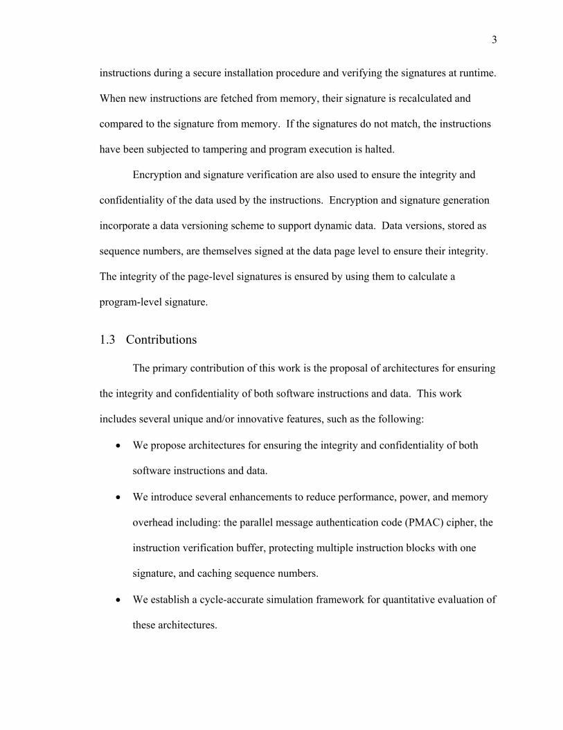
instructions during a secure installation procedure and verifying the signatures at runtime.
When new instructions are fetched from memory, their signature is recalculated and
compared to the signature from memory. If the signatures do not match, the instructions
have been subjected to tampering and program execution is halted.
Encryption and signature verification are also used to ensure the integrity and
confidentiality of the data used by the instructions. Encryption and signature generation
incorporate a data versioning scheme to support dynamic data. Data versions, stored as
sequence numbers, are themselves signed at the data page level to ensure their integrity.
The integrity of the page-level signatures is ensured by using them to calculate a
program-level signature.
1.3 Contributions
The primary contribution of this work is the proposal of architectures for ensuring
the integrity and confidentiality of both software instructions and data. This work
includes several unique and/or innovative features, such as the following:
• We propose architectures for ensuring the integrity and confidentiality of both
software instructions and data.
• We introduce several enhancements to reduce performance, power, and memory
overhead including: the parallel message authentication code (PMAC) cipher, the
instruction verification buffer, protecting multiple instruction blocks with one
signature, and caching sequence numbers.
• We establish a cycle-accurate simulation framework for quantitative evaluation of
these architectures.

4
• We use the cycle-accurate simulator to evaluate performance and power
overhead.
1.4 Outline
The remainder of this thesis is organized as follows. Chapter 2 presents an
overview of several threats to computer security. Chapter 3 surveys existing proposals
for hardware support meant to preserve software and/or data integrity and/or
confidentiality. Chapter 4 details our proposed architecture for preserving software
integrity and confidentiality, while Chapter 5 details our proposed architecture for
preserving data integrity and confidentiality. Chapter 6 describes the experimental
environment used to evaluate these architectures. Chapter 7 evaluates these architectures
both qualitatively and with quantitative test results for various benchmarks. Chapter 8
concludes the thesis and suggests avenues for further research.

5
CHAPTER 2
COMPUTER SECURITY
This chapter briefly examines several types of attacks that embedded systems may
experience. First we look at software-based attacks, where the attacker already has
access to a system, either directly or over a network. Next we look at physical attacks,
where the attacker has physical access to the system but not necessarily software access.
Finally we examine side-channel attacks, in which the attacker attempts to gain
knowledge about the system by indirect analysis.
2.1 Software Attacks
Software attacks require the attacker to have some form of access to the target
computer system. This could be direct access, with a lower permission level than the
attacker desires. The access could also be across a network, which would require the
attacker to sniff the system’s open ports, looking for services with known vulnerabilities.
The goal of software attacks is to modify a running program by injecting and executing
code. The foreign instructions must be injected into memory, and then the return address
of the currently executing function must be overwritten to force the processor to execute
the injected instructions. These attacks are only briefly documented here; a more detailed
treatment can be found in [4].

6
2.1.1 Buffer Overflow Attacks
A common class of attacks is buffer overflow. These attacks take advantage of
I/O instructions that simply store incoming data to a buffer, without bothering to check to
see if the amount of incoming data will exceed the buffer size. After the buffer fills,
memory locations beyond the buffer are overwritten. Most systems have stacks that grow
counter to memory address growth. If the buffer is on the stack, then this attack can
overwrite the data at any address on the stack beyond the buffer with malicious
instructions. This overwrite includes the return address, allowing the attacker to divert
the program to the newly injected instructions. If the buffer is on the heap near a function
pointer, then the attacker’s goal is to inject code and overwrite that function pointer.
2.1.2 Format String Attacks
Format string attacks take advantage of printf-family instructions that take a
format string as an input. These functions will accept any pointer and interpret the
contents of memory at that address as a format string. By skillfully manipulating the
inputs passed to the printf function, the attacker can read from any address in memory.
The %n format character presents an additional vulnerability. This character causes a
printf function to write the number of characters output by the function before it reached
%n to a specified address. A skillful attacker could use this to write an arbitrary integer
to any address.
2.1.3 Integer Error Attacks
Errors arising from integer operations cannot be used as a direct attack. However,
integer errors can facilitate other forms of attacks. For instance, an unsigned integer

7
overflow can result in a smaller number than expected. If this is used to allocate a buffer,
then the buffer will also be smaller than expected. This exposes the system to a buffer
overflow attack, even if subsequent input operations using that buffer check input length.
A more thorough treatment of integer error attacks may be found in [5].
2.1.4 Dangling Pointer Attacks
Dangling pointers become an issue if the free function is called twice for the same
pointer. The vulnerability arises from the way that the GNU C library handles memory
allocation [6]. When a chunk of memory is freed, it is inserted into a doubly linked list of
free chunks. If free is called twice, the pointers to the next and previous entries may
wind up pointing back to the same chunk. An attacker may write malicious code to the
chunk’s data area and put a pointer to that code in place of the pointer to the previous list
entry. If that chunk is allocated again, the memory manager will try to unlink the chunk
from the list, and will write the attacker’s pointer to an address calculated from the
pointer to the next entry. If that address happens to contain a function’s return address,
then a successful attack has been accomplished.
2.1.5 Arc-Injection Attacks
An arc injection or “return-into-libc” involves overwriting a return address such
that control flow is disrupted. Oftentimes the address of a library function is used.
Library system calls can be used to spawn other processes on the system with the same
permissions as the compromised program. If the operating system (OS) itself is
compromised, then the attacker can run a malicious program that will have the ability to
access any and every memory location.

8
2.2 Physical Attacks
In contrast to software attacks, physical attacks involve tampering with the actual
computer hardware. Probes are often inserted on the address and data bus, allowing the
attacker to monitor all transactions and override data coming from memory with his/her
own data. This is a tool often used in industrial and military espionage. This section
describes three such attacks: spoofing, splicing, and replay.
2.2.1 Spoofing Attacks
A spoofing attack occurs when an attacker intercepts a request for a block of
memory, and then manually supplies a block of his/her choice. This block may contain
either data or instructions of a malicious nature. In an unsecured system, the processor
naïvely conducts a bus cycle, and is unaware that the data it received came from an
attacker rather than from main memory. The spoofing process is illustrated in Figure 2.1.
The processor initiates a bus read cycle for a block at memory location Ai. The attacker
intercepts the request and supplies a potentially malicious block Mi instead of the correct
block Ai.

9
BusRd(Ai)
Ai
Mi
Attacker
Processor MainMemory
Figure 2.1 Spoofing Attack
2.2.2 Splicing Attack
Splicing attacks involve intercepting a request for a block of memory and then
supplying the data from a different block. The supplied block is a valid block from
somewhere in the address space, but it is not the actual block that the processor
requested. This attack may be performed with either data or instruction blocks. Once
again, the unsecured processor is unaware that it has received the incorrect memory
block. The splicing attack methodology is illustrated in Figure 2.2. The processor
initiates a bus read cycle for a block at memory location Ai. The attacker intercepts the
request and supplies a valid block from memory, but from address Aj rather than the
desired address.

10
Ai
Aj
Aj
BusRd(Ai)
Attacker
Processor MainMemory
Figure 2.2 Splicing Attack
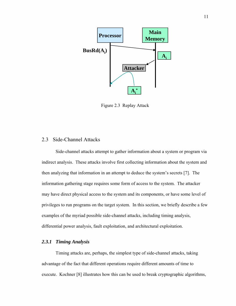
2.2.3 Replay Attacks
In a replay attack, the attacker intercepts a request for a block of memory, and
then supplies an older copy of that block. This is primarily a concern for data blocks
rather than instructions. The supplied block was correct at some point in the past, but
now it may be obsolete. The replay attack process is illustrated in Figure 2.3. The
processor initiates a bus read cycle for the data block at address Ai. The attacker
intercepts the request and returns an older version of that block, which may be different
from the current version in memory.
11
Ai
Ai*
BusRd(Ai)
Attacker
Processor MainMemory
Figure 2.3 Replay Attack
2.3 Side-Channel Attacks
Side-channel attacks attempt to gather information about a system or program via
indirect analysis. These attacks involve first collecting information about the system and
then analyzing that information in an attempt to deduce the system’s secrets [7]. The
information gathering stage requires some form of access to the system. The attacker
may have direct physical access to the system and its components, or have some level of
privileges to run programs on the target system. In this section, we briefly describe a few
examples of the myriad possible side-channel attacks, including timing analysis,
differential power analysis, fault exploitation, and architectural exploitation.
2.3.1 Timing Analysis
Timing attacks are, perhaps, the simplest type of side-channel attacks, taking
advantage of the fact that different operations require different amounts of time to
execute. Kochner [8] illustrates how this can be used to break cryptographic algorithms,
12
given a known algorithm and either known plaintext or known ciphertext. He uses
timing analysis to determine the secret exponent in the Diffie-Hellman algorithm, factor
RSA private keys, and determine the private key used by the Digital Signature Standard
algorithm.
2.3.2 Differential Power Analysis
A microprocessor’s power consumption at any given moment can indicate what
operations it is performing. A differential power analysis can be used to determine what
instructions are executed and when. Kocher et al. [9] discuss how to break a known,
data-driven encryption algorithm using such an attack. Instantaneous CPU power
consumption is measured at intervals during a cryptographic operation, forming a trace.
Multiple traces can be compiled and compared, revealing patterns produced by the
execution of certain instructions. Since the encryption algorithm is both known and data-
driven, the data being processed can be revealed solely from the power traces.
2.3.3 Fault Exploitation
A fault exploitation attack takes advantage of hardware faults to discover secrets.
These hardware faults may be transiently occurring within the processor, or induced
externally. Boneh et al. [10] describe a simple fault exploitation attack, whereby the
modulus used by an RSA algorithm may be calculated. A signature must be calculated
from the same data two times. One signature is calculated without a hardware fault. The
second is calculated in the presence of a hardware fault, either transient or induced. The
modulus of the RSA system can then be factored by analyzing the difference between the
13
two signatures. Boneh et al. go on to break even more sophisticated cryptographic
schemes using similar techniques.
2.3.4 Architectural Exploitation
Due to the well-known effect of Moore’s Law, microprocessor designers have
been able to introduce more and more advanced features. Sometimes these advanced
features may be exploited to reveal information about the processor. A prime example of
an architectural exploitation attack is the Simple Branch Prediction Analysis attack
devised by Aciiçmez et al. [11]. This attack expands on the classical timing attack by
taking advantage of the branch prediction unit and multi-threading capabilities of the
Pentium 4 processor. A spy process is executed in parallel with a process performing a
known cryptographic algorithm. The spy process executes branch instructions, flooding
the processor’s branch target buffer (BTB), while measuring the execution time required
for those branch instructions. When the cryptographic process executes a branch
instruction that results in the branch not being taken, no BTB eviction is needed. Thus,
the next time the spy process executes a corresponding branch, it will execute quickly,
thereby revealing that the cryptographic process had a branch not taken. Conversely, a
taken branch in the cryptographic process results in a BTB eviction, which in turn causes
a spy process branch to take longer to execute, revealing that the cryptographic process
had a taken branch. The recorded trace of branches that were taken and not taken can
then be used to deduce the cryptographic secret key. This attack relies on detailed
information about the underlying hardware and software, but such information is often
available and can be obtained using microbenchmarks [12].

14
CHAPTER 3
RELATED WORK
In this chapter, we briefly survey several architectural techniques that have been
proposed to support the software and data integrity and confidentiality. Security may be
approached from both the software and hardware perspectives. Software techniques may
be classified as static (relying on the detection of security vulnerabilities in code at design
time) and dynamic (adding code to enhance security at runtime). A survey of static and
dynamic software techniques may be found in [4]. Hardware techniques rely primarily
on hardware to ensure security, often with some degree of software support. This chapter
focuses on hardware techniques, as our proposed security architectures are hardware-
oriented. We first examine various proposals from academia, which are well
documented. Then we examine industrial security solutions, which are not as well
documented due to their proprietary nature.
3.1 Academic Proposals
Several techniques have been put forth to address common types of attacks. Xu
et al. [13] and Ozdoganoglu et al. [14] propose using a secure hardware stack to defend
against stack buffer overflow attacks. Tuck et al. [15] suggest using encrypted address

15
pointers. Suh et al. [16] and Crandall and Chong [17] propose that all data coming from
untrusted channels be tagged, thus not allowed to be used as a jump target.
The execute-only memory (XOM) architecture proposed by Lie et al. [18]
provides an architecture meeting the requirements of integrity and confidentiality. Main
memory is assumed to be insecure, so all data entering and leaving the processor while it
is running in secure mode is encrypted. This architecture was vulnerable to replay
attacks in its original form, but that vulnerability was corrected in [19]. The drawbacks
to this architecture are its complexity and performance overhead. XOM requires
modifications to the processor core itself and to all caches, along with additional security
hardware. This architecture also incurs a significant performance overhead, by its
designers’ estimation, of up to 50%.
The high overhead of XOM is reduced by the architectural improvements
proposed by Yang et al. [20]. They only address confidentiality, as their improvements
are designed to work with XOM, which already addresses integrity concerns. They
propose to use a one-time pad (OTP) scheme for encryption and decryption, in which
only the pad is encrypted and then exclusive or-ed with plaintext to produce ciphertext, or
with ciphertext to produce plaintext. They augment data security by including a sequence
number in the pad for data blocks, and require an additional on-chip cache for said
sequence numbers. While their scheme greatly improves XOM’s performance, it inherits
its other weaknesses.
Gassend et al. [21] propose to verify untrusted memory using a tree of hashes.
They only address integrity, suggesting that their architecture can be added to a system
such as XOM, which will handle confidentiality concerns. The use of a hash tree

16
introduces significant bandwidth overhead, which is alleviated by integrating the hash
mechanism with system’s caches. However, their integrity-only overhead is still high,
with a maximum of 20% for the most efficient architecture they propose.
Lu et al. [22] propose a similar architecture, using a message authentication code
(MAC) tree. MACs are computed for each cache block, incorporating its virtual address
and a secret application key. For higher level nodes, MACs are computed using those
from the lower level and a random number generated from thermal noise in the processor.
They propose to enhance performance by caching MAC data on the chip. This MAC tree
architecture does show an improvement over the hash tree proposed by Gassend et al.,
but it still introduces an average performance overhead of between 10% and 20%.
Suh et al. [23] propose an architecture that addresses confidentiality and overall
integrity. Their architecture uses one-time pad (OTP) encryption to provide
confidentiality with relatively low overhead. However, since their cryptographic
functions take a timestamp as an input, they propose that the entire protected memory be
re-encrypted on the unlikely event of a timestamp counter rollover. To reduce overhead
from integrity checking, they propose to construct a log of memory accesses using
incremental multiset hashes. They assume that a program produces meaningful, signed
outputs either at the end of its execution or at discrete intervals during execution. Their
architecture verifies the hashed memory access sequences only when those outputs are
produced. Since verification occurs infrequently, it introduces negligible overhead. The
major drawback is that tampering is not immediately evident, leaving the system
potentially vulnerable between verifications.

17
Another architecture proposed by Suh and his colleagues [24] is the AEGIS
secure processor. They describe physical unclonable functions (PUFs) to generate the
secrets needed by their architecture. Memory is divided into four regions based on
whether it is static or dynamic (read-only or read-write) and whether it is only verified or
is both verified and confidential. They allow programs to change security modes at
runtime, starting with a standard unsecured mode, then going back and forth between a
mode supporting only integrity verification and a mode supporting both integrity and
confidentiality. They also allow the secure modes to be temporarily suspended for library
calls. This flexibility comes at a price; their architecture assumes extensive operating
system and compiler support.
The work of Milenković et al. [4, 25, 26] provides the foundation for the research
documented in this thesis. They introduced many of the elements that will be used in this
current work and described below. Their proposed architecture addresses only the
integrity of instructions, and involves signing instruction blocks during a secure
installation procedure. These signatures are calculated using instruction words, block
starting addresses, and a secret processor key, and are stored together in a table in
memory. At runtime, these signatures are recomputed and checked against signatures
fetched from memory. The cryptographic function used in the architecture is a simple
polynomial function implemented with multiple input shift registers. The architecture is
updated in [27] and [28], adding AES encryption to increase cryptographic strength and
embedding signatures with instruction blocks rather than storing them in a table. This
architecture remains vulnerable to splicing attacks, since signatures in all programs use
the same key.
18
Drinić and Kirovski [29] propose a similar architecture to that of Milenković
et al., but with greater cryptographic strength. They use a cipher block chaining (CBC-)
MAC cipher, and include the signatures in the cache line. They propose to reduce
performance overhead by reordering basic blocks, so that instructions that may not be
safely executed in a speculative manner are not issued until signature verification is
complete. The drawback to this approach is that it requires significant compiler support,
and may consistently hide the verification overhead. Furthermore, their architecture does
not address confidentiality, and is vulnerable to replay and splicing attacks.
3.2 Industrial Solutions
Microprocessor vendors Intel and Advanced Micro Devices (AMD) have each
introduced features to prevent buffer overflow attacks. Intel calls their feature the
Execute Disable Bit [30], which prohibits the processor from executing instructions that
originate from certain areas of memory. AMD’s No Execute (NX) Bit [31] is very
similar to Intel’s Execute Disable Bit. The NX bit is stored in the page table, and is
checked on translation look-aside buffer (TLB) misses. Both Intel and AMD allow
software to disable this functionality.
International Business Machines (IBM) has developed the SecureBlue
architecture [32]. Like the academically-proposed techniques described above, it relies
on cryptography to ensure integrity and confidentiality of both software and data.
SecureBlue is intended to be incorporated into existing microprocessor designs.
ARM markets the TrustZone security architecture [33], designed to augment
ARM microprocessors. It relies on both hardware and software support. The hardware
component uses cryptography to address integrity and confidentiality, allowing the

19
processor to run in either a secure or non-secure mode. The software support includes the
TrustZone Monitor, which augments the operating system and provides an application
programming interface (API) for secure programs.
Maxim (formerly Dallas Semiconductor) manufactures the DS5250 secure
microprocessor [34]. The DS5250 is designed to serve as a co-processor for embedded
systems with traditional, non-secure microprocessors. Maxim proposes that the co-
processor perform security-sensitive functions while the primary processor performs less
sensitive operations. The DS5250 contains a non-volatile on-chip memory that is erased
if physical tampering is detected. This memory is used to store the processor’s secret
key, and can also be used to securely store other sensitive data. The DS5250 can also
access external memory, using cryptography to ensure integrity and confidentiality of
such accesses.

20
CHAPTER 4
HARDWARE SUPPORTED TECHNIQUES FOR ENSURING SOFTWARE INTEGRITY AND CONFIDENTIALITY
In this chapter we present the proposed hardware architecture supporting software
integrity and confidentiality. We begin with a general overview of the proposed
architecture followed by a more detailed discussion of the required hardware. Further
design choices are then explored that reduce performance, energy, and memory overhead.
4.1 Framework Overview
The framework for software integrity and confidentiality encompasses three
stages [25]. The first stage is a secure installation procedure, in which binary executables
are signed and optionally encrypted for a particular processor. The second stage is secure
loading, in which the computer system prepares to run the secure program. The final
stage is secure execution, where the program is run, such that its integrity and/or
confidentiality is maintained.
The proposed architecture allows three levels of protection: unprotected, software
integrity only mode (SIOM), and software integrity and confidentiality mode (SICM). In
the SIOM mode only software integrity is guaranteed; all instructions are stored in binary
plaintext that could be read by an adversary. The SICM mode ensures both software

21
integrity and confidentiality by further encrypting the instructions. Figure 4.1 shows an
overview of the three stages of the proposed architecture when running in SICM mode.
Original Code Signed Code
Secure Installation
Trusted Code
Signature Match
Signature Fetch
Instruction Fetch
Secure Execution
CalculateSignature
EKey3(I-Block)
Signature
Encrypt
Generate Program Keys(Key1,Key2,Key3)
Secure ModeEKey.CPU(Key1)EKey.CPU (Key2)EKey.CPU(Key3)
Encrypt
I-Block
ProgramLoading
Decrypt Program Keys(Key1,Key2,Key3)
Decrypt I-Block
=?
CalculateSignature
Figure 4.1 Overview of Architecture for Trusted Instruction Execution
4.1.1 Secure Installation
The process by which an unprotected program is installed on the system to take
advantage of hardware support for software integrity and/or confidentiality is called
secure installation. The secure installation procedure presented here is similar to that
proposed by Kirovski et al. [35]. The CPU must perform secure installations in an
atomic manner, and must not reveal any secret information during or after the
installation.

22
Key generation is the first step in secure installation. SIOM mode requires two
unique program keys, while SICM mode requires three. These keys, designated Key1,
Key2, and Key3, are randomly generated by the CPU. They are then encrypted on-chip
using the processor’s internal secret key, Key.CPU. The encrypted keys are brought off-
chip and stored in the header of the secure executable. Note that these keys should only
leave the CPU in encrypted form; the plain-text keys must stay on the CPU.
The next step in the secure installation process is signature calculation.
Signatures must be calculated for each instruction block (I-block). Protected I-block size
must be determined at this point. A natural protected I-block size is the line size of the
lowest level instruction cache (I-cache) line. Smaller protected I-block sizes will yield a
higher memory overhead, so a multiple of the I-cache line size may be chosen. This
paper focuses on cases where the protected I-block size is either equal to or twice the size
of the I-cache line size.
A protected I-block’s signature is a cryptographic function of three factors: the
block’s starting virtual address (alternatively, its offset from the beginning of the
program’s code section), two of the program keys generated earlier, and the instruction
words within the I-block. The use of unique program keys prevents the execution of any
unauthorized code that may be inserted or injected after the installation process, and also
protects against a splicing attack involving a valid I-block from another secure program.
The use of the instruction words and the block address prevent spoofing and splicing
from within the same program.
Encryption of program executables is required for SICM mode. Cryptographic
schemes must balance two requirements. First, a high level of security is absolutely
23
necessary. Secondly, decryption should be fast, thus causing a low runtime performance
overhead. The proposed architecture uses a variant of the one-time pad (OTP) encryption
algorithm, which satisfies both requirements.
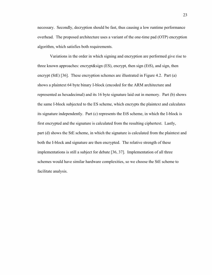
Variations in the order in which signing and encryption are performed give rise to
three known approaches: encrypt&sign (ES), encrypt, then sign (EtS), and sign, then
encrypt (StE) [36]. These encryption schemes are illustrated in Figure 4.2. Part (a)
shows a plaintext 64 byte binary I-block (encoded for the ARM architecture and
represented as hexadecimal) and its 16 byte signature laid out in memory. Part (b) shows
the same I-block subjected to the ES scheme, which encrypts the plaintext and calculates
its signature independently. Part (c) represents the EtS scheme, in which the I-block is
first encrypted and the signature is calculated from the resulting ciphertext. Lastly,
part (d) shows the StE scheme, in which the signature is calculated from the plaintext and
both the I-block and signature are then encrypted. The relative strength of these
implementations is still a subject for debate [36, 37]. Implementation of all three
schemes would have similar hardware complexities, so we choose the StE scheme to
facilitate analysis.

24
3000a80: e3a02000 3000a84: e50b2030 3000a88: e59f122c 3000a8c: e5812000 3000a90: e50b2034 3000a94: e1a06000 3000a98: e59f0220 3000a9c: eb002c5b 3000aa0: e2505000 3000aa4: 0a000033 3000aa8: e1a00005 3000aac: e3a0102f 3000ab0: eb004ad2 3000ab4: e3500000 3000ab8: 0a000004 3000abc: e59f3200 3000ac0: 8228f6a9 3000ac4: c9cefbda 3000ac8: 15b99534 3000acc: 62e8bee6
3000a80: 579a754c 3000a84: c672ef35 3000a88: 2aabbff5 3000a8c: 75fbfcea 3000a90: 9f733369 3000a94: 2eefaeec 3000a98: 2d7473aa 3000a9c: 640ce79b 3000aa0: 4148cddf 3000aa4: 7bedbe21 3000aa8: 5afce7f8 3000aac: e5486c46 3000ab0: 066ce464 3000ab4: 6caac2ef 3000ab8: 0c4b1a49 3000abc: 6a9e6cc8 3000ac0: 8228f6a9 3000ac4: c9cefbda 3000ac8: 15b99534 3000acc: 62e8bee6
3000a80: 579a754c 3000a84: c672ef35 3000a88: 2aabbff5 3000a8c: 75fbfcea 3000a90: 9f733369 3000a94: 2eefaeec 3000a98: 2d7473aa 3000a9c: 640ce79b 3000aa0: 4148cddf 3000aa4: 7bedbe21 3000aa8: 5afce7f8 3000aac: e5486c46 3000ab0: 066ce464 3000ab4: 6caac2ef 3000ab8: 0c4b1a49 3000abc: 6a9e6cc8 3000ac0: f6231db4 3000ac4: 3495cc9c 3000ac8: 17350aac 3000acc: 74d7ac7b
3000a80: 579a754c 3000a84: c672ef35 3000a88: 2aabbff5 3000a8c: 75fbfcea 3000a90: 9f733369 3000a94: 2eefaeec 3000a98: 2d7473aa 3000a9c: 640ce79b 3000aa0: 4148cddf 3000aa4: 7bedbe21 3000aa8: 5afce7f8 3000aac: e5486c46 3000ab0: 066ce464 3000ab4: 6caac2ef 3000ab8: 0c4b1a49 3000abc: 6a9e6cc8 3000ac0: b5f5be91 3000ac4: cb72dd15 3000ac8: 831ef1a2 3000acc: 6b1f35a5
(a) (b) (c) (d)
Figure 4.2 Signed Binary Instruction Block: (a) Signed plaintext, (b) ES, (c), EtS, (d) StE
4.1.2 Secure Loading
The secure loading process prepares a secure executable to run on the secure
architecture. During this process, the encrypted program keys are read from the secure
executable header. These are loaded into special-purpose registers on the CPU and
decrypted using the processor’s secret key (Key.CPU). As mentioned above, these keys
should never leave the CPU as plain-text. They may only be accessed by dedicated on-
chip hardware resources, such as the instruction block signature verification unit
(IBSVU), which shall be discussed later. If a context switch occurs, these keys must be
re-encrypted before leaving the processor to be stored in the process control block. When
the context switches back to the secure program, they must be re-loaded into the
processor and decrypted once again before secure execution may resume.

25
4.1.3 Secure Execution
The secure execution stage is when the secured program actually runs. The
proposed architectural enhancements come into play whenever instructions are fetched
from memory. Since the CPU chip is assumed to be secure, and instruction caches may
be assumed to be read-only, instructions should be trusted once they are in the cache.
Thus the architectural enhancements should operate in conjunction with the highest I-
cache level, and it is convenient for the protected I-block size to be some multiple of the
cache line size. If the system has no instruction cache, then the size of the fetch buffer
may determine protected I-block size. Throughout the rest of the paper, we assume,
without loss of generality, a system with separate Level 1 instruction and data caches, and
no Level 2 caches. The general operation of the proposed mechanisms may be simply
explained for the case where protected I-block size equals the cache line size. The case
where the protected I-block size is double the cache line size will be explored below in
Section 4.3.3.
Because the I-cache is a trusted resource, signature verification need only occur
on a cache miss. Signatures are not cached, and are not available during execution, so
they may reside outside the processors virtual address space. This requires additional
logic to translate the original virtual instruction block address to the actual address of the
instruction block in memory. Page padding must also be taken into account. Once the
correct addresses are available, the protected I-block and its signature are fetched from
memory and decrypted as needed. The signature is recalculated using the newly fetched
I-block. If the calculated signature matches the fetched signature, then the I-block can be
trusted. If the signatures do not match, then the I-block has been subjected to tampering.
26
The processor then traps to the operating system, which should take appropriate action to
terminate the process. The simplest implementation would stall the processor until the I-
block’s signature has been verified. We call this a wait ‘til verified (WtV) scheme.
However, given certain additional hardware resources, a run-before-verification (RbV)
scheme may be implemented. In that case, the processor may be allowed to continue
execution once the I-block has been fetched and is in the cache. This concept will be
elaborated on in Section 4.3.2.
4.1.4 Other Considerations
At this point, we must consider two special cases. The first involves dynamically
linked libraries (DLLs), which contain binary executable code that is potentially shared
among multiple programs. The simplest option would be to forbid the use of DLLs on
the secured system. A slightly more complex option would be to introduce a bit in the
page table and translation lookaside buffer (TLB) specifying whether or not that page
contains protected code. Instruction pages within DLLs could then be marked as
unprotected. Even more complex would be to further enhance the page table (and TLB)
to mark the page as belonging to a DLL. DLL instructions would then be protected using
additional processor-specific keys. Throughout the remainder of the thesis, we assume
that DLLs are handled with one of these three methods.
The second case involves instructions that are generated at runtime, including
just-in-time compilation and interpreted code. One option is to flag pages containing
dynamically generated instructions as unprotected. Another option would be to have the
program generating the instructions insert signatures as I-blocks are created. This

27
requires that the generating program be trusted, and thus the output of the program would
also be trusted.
4.2 Basic Implementation
This section describes a simple, basic implementation of the instruction protection
architecture. We first describe the cryptographic operations required for the simple CBC-
MAC cipher, and then analyze the overhead incurred by this implementation. We finally
discuss the hardware requirements for the architecture.
4.2.1 Implementation Details
The simplest implementation of the instruction protection architecture utilizes the
cipher block chaining message authentication code (CBC-MAC) algorithm [29].
Signature generation is performed on-chip, using a dedicated hardware resource. Initial
signature generation and possibly encryption is performed during the secure installation
stage. During secure execution, the signatures must be recalculated after decryption (if
necessary).
Signature generation may be illustrated by choosing an exemplary architecture.
We assume a 32-bit architecture with 32 byte protected I-blocks. Each I-block will be
appended with a 128-bit signature. The I-block is divided into two sub-blocks of equal
size, I0:3 and I4:7. Let A be the starting virtual address of the I-block, SP represent a
secure padding function, and KEY1 and KEY2 be the first two of the aforementioned
unique program keys.

28
When using the CBC-MAC cipher, the signature S for the I-block is calculated
according to Equation (4.1). The form of the signature function in this case is conducive
to the sequential chaining provided by the CBC-MAC.
( )( )[ ].)()()( 13:027:42 ASPAESxorIAESxorIAESS KEYKEYKEY= (4.1)
Equations (4.2) and (4.3) illustrate the encryption functions for the same sample
system used to illustrate signature generation. Sub-blocks are defined as before. The
encrypted versions of the sub-blocks, C0:3 and C4:7, are calculated according to
Equation (4.2). Note that KEY3 is another unique program key. This key is distinct from
those used for signature generation since authentication and encryption should not use the
same keys [38]. The encrypted signature eS is calculated according to Equation (4.3).
( ) ,1..0,))(()()( 334:434:4 == ++ iSBASPAESxorIC iKEYiiii (4.2)
( ).))((3 eSASPAESxorSeS KEY= (4.3)
During secure installation, the I-block (possibly encrypted) is stored on disk or in
memory, followed by its signature (also possibly encrypted). Protected I-blocks and their
signatures should not cross page boundaries. Therefore, page padding may be required
after the last signature in the page to ensure that the next I-block starts on the next page.
Signatures must be recalculated on instruction cache misses during secure
execution. The signature cS is recalculated in the same manner in which the original
signature S was calculated during secure installation. Recalling Equation (4.1), this
calculation requires the encryption of secure padded virtual sub-block addresses. This
29
encryption should happen in parallel with the memory access, thus overlapping some of
the cryptographic latency with memory access latency.
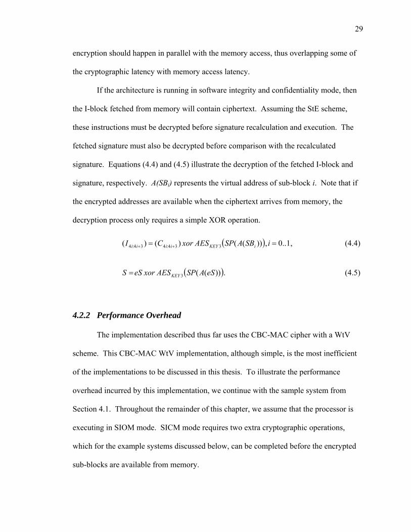
If the architecture is running in software integrity and confidentiality mode, then
the I-block fetched from memory will contain ciphertext. Assuming the StE scheme,
these instructions must be decrypted before signature recalculation and execution. The
fetched signature must also be decrypted before comparison with the recalculated
signature. Equations (4.4) and (4.5) illustrate the decryption of the fetched I-block and
signature, respectively. A(SBi) represents the virtual address of sub-block i. Note that if
the encrypted addresses are available when the ciphertext arrives from memory, the
decryption process only requires a simple XOR operation.
( ) ,1..0,))(()()( 334:434:4 == ++ iSBASPAESxorCI iKEYiiii (4.4)
( ).))((3 eSASPAESxoreSS KEY= (4.5)
4.2.2 Performance Overhead
The implementation described thus far uses the CBC-MAC cipher with a WtV
scheme. This CBC-MAC WtV implementation, although simple, is the most inefficient
of the implementations to be discussed in this thesis. To illustrate the performance
overhead incurred by this implementation, we continue with the sample system from
Section 4.1. Throughout the remainder of this chapter, we assume that the processor is
executing in SIOM mode. SICM mode requires two extra cryptographic operations,
which for the example systems discussed below, can be completed before the encrypted
sub-blocks are available from memory.

30
The procedures to be followed on an instruction cache miss are described in
Figure 4.3. The verification latency introduced by this implementation is illustrated in
Figure 4.4. In addition to the earlier assumptions, we assume bus width of 64 bits, and
memory latency of 12 clock cycles for the first 64-bit chunk and 2 clock cycles for
subsequent chunks. The darkly shaded blocks in the figure’s cryptographic pipeline
represent encrypting the sub-block addresses using Key1, which is necessary for
signature recalculation. The lightly shaded blocks represent signature recalculation using
Key2.
Figure 4.3 I-Cache Miss Algorithm, CBC-MAC Implementation
1. Probe I-cache for desired block. If found, return, otherwise continue.
2. Initiate fetch of instruction block and signature from memory.
3. Start cryptographic calculation using KEY1 on instruction block address (see Equation (4.1)).
4. If SICM, start cryptographic calculations using KEY3 on instruction sub-block and signature addresses; decrypt instruction block and signature when available (see Equations (4.4) and (4.5)).
5. Calculate signature for instruction block (see Equation (4.1))
6. Compare calculated signature to signature fetched from memory. If mismatch, trap to operating system.

31
= ?
0 2 4 6 8 10 12 14 16 18 20 22 24 26 28 30 32 34 36 38Time (clock cycles)
Memorypipeline
Cryptopipeline
S
cS
Verification Latency
I0:1 I2:3 I4:5 I6:7 S0:1 S2:3
SP(A)
Figure 4.4 Verification Latency, CBC-MAC WtV Implementation
Measured from the cycle at which the last instruction word is available (at which
point the processor would normally resume execution), this implementation has a
verification latency of 21 clock cycles, including a clock cycle for signature comparison.
4.2.3 Hardware Requirements
Each of the three stages of this architecture requires at least some hardware support
on the CPU. Common to all three stages, however, is the need for a cryptographic cipher
unit that implements the Advanced Encryption Standard (AES). There are multiple
existing hardware designs for such a hardware unit, two of which are convenient for use
with the proposed architecture. The first of these two, the CBC-MAC, has already been
mentioned. The other shall be discussed in Section 4.3.1.
In addition to the cryptographic unit, the secure installation stage requires a
unique processor key and the ability to generate random program keys. Manufacturers
have long had the ability to embed unique read-only data on individual chips. A similar
process may be used to embed the CPU’s secret key. This key must only be used

32
internally; it should never leave the chip. The processor must also be able to generate
program keys at random. A variety of methods exist for random number generation,
including thermal noise within the processor [39] and physical unclonable functions
(PUFs) [24]. The program keys must never leave the processor in plain-text form.
During secure installation, these keys are encrypted using the crypto unit; the encrypted
version of the keys may leave the CPU.
The processor must have a mechanism to enter a secure installation mode. One
option is to augment the instruction set, providing an instruction to initiate secure
installation. This instruction would trigger a state machine to handle secure installation
procedures such as key generation, signature generation, and encryption. Another option
is to trigger secure installation with a separate piece of hardware, such as a smart card
reader. This piece of hardware would then serve as a key, unlocking the secure
installation capabilities.
The secure loading stage requires a state machine to load the encrypted program
keys from a specified location in memory and decrypt them. The decrypted keys must be
stored in special purpose registers in the CPU, and must never leave the chip. As stated
earlier, context switch handling must also be modified to encrypt the keys and write them
out to the process control block.
The secure execution stage requires extensive hardware support in the form of the
instruction block signature verification unit (IBSVU). The IBSVU, illustrated in
Figure 4.5, contains the cryptographic unit, which is also used by the secure installation
and loading stages. The IBSVU also contains the address translation logic and a buffer to
store a signature waiting to be compared. It may also contain other hardware resources as

33
described in Section 4.3. The IBSVU must work very closely with the cache controller,
and could in some ways be considered an extension of the cache controller.
With the exception of external key hardware to trigger secure installation mode,
all of this hardware may be implemented with relatively low complexity. The complexity
added to the processor is qualitatively evaluated in Section 7.1.
L1I-cache
L1 D-cache
MMU
Datapath
FPUs IF
Control IBSVU
Processor
Data bus
I-cache
… …
… …
… …
… …
… …
… …
… …
… …
sig
CryptoPipeline
XOR=?
cS
S
sig
Program keys
match
Figure 4.5 Instruction Block Signature Verification Unit
4.3 Reducing Overhead
This section discusses schemes for reducing the relatively high overhead of the
implementation described above. We start by introducing the parallelizable MAC
(PMAC) algorithm, which reduces cryptographic latency. We then discuss the

34
implementation of an RbV scheme that almost completely hides verification latency.
Finally we address memory overhead by protecting multiple I-blocks with one signature.
4.3.1 PMAC
Performance overhead can be greatly reduced by using a parallelizable MAC
cipher. The PMAC algorithm was developed by Black and Rogaway [40], who show that
it approximates a random permutation. As its name implies, the PMAC can compute
multiple cryptographic functions in parallel, allowing for an efficient pipeline.
The PMAC cipher allows signatures for each sub-block to be calculated in
parallel. In this case, we can calculate a signature Sig(SBi) for each sub-block i according
to Equation (4.6). The signature S of the whole protected I-block is an exclusive or
(XOR) function of the signatures of the sub-blocks, as expressed in Equation (4.7).
( )[ ] ,1..0,))(()()( 134:42 == + iSBASPAESxorIAESSBSig iKEYiiKEYi (4.6)
.)()( 10 SBSigxorSBSigS = (4.7)
The procedures to be followed for a PMAC implementation on an I-cache miss
are outlined in Figure 4.6. Figure 4.7 illustrates the verification latency for the PMAC
WtV implementation for the sample machine discussed above. Using PMAC,
verification latency is reduced to 13 cycles, including a clock cycle for signature
comparison. This is an improvement over the CBC-MAC, but still introduces a
significant performance overhead.

35
Figure 4.6 I-Cache Miss Algorithm, PMAC Implementation
0 2 4 6 8 10 12 14 16 18 20 22 24 26 28 30Time (clock cycles)
Memorypipeline
Cryptopipeline
SP(A(SB0 ))SP(A(SB1 ))
S
cS
Verification Latency
I0:1 I2:3 I4:5 I6:7 S0:1 S2:3
= ?
Figure 4.7 Verification Latency, PMAC WtV Implementation
1. Probe I-cache for desired block. If found, return, otherwise continue.
2. Initiate fetch of instruction block and signature from memory.
3. Start cryptographic calculations using KEY1 on instruction sub-block addresses (see Equation (4.6)).
4. If SICM, start cryptographic calculations using KEY3 on instruction sub-block and signature addresses; decrypt instruction blocks and signature once available (see Equations (4.4) and (4.5)).
4. Calculate signature for instruction block (see Equations (4.6) and (4.7))
5. Compare calculated signature to signature fetched from memory. If mismatch, trap to operating system.

36
4.3.2 Run-Before-Verification
Ideally, the verification latency should be completely hidden, thus introducing no
performance overhead. This would require that the processor resume executing
instructions as soon as the whole instruction cache line is available. Such a scheme is
called Run-before-Verification (RbV). The instruction block, however, may have been
subject to tampering, which will not be evident until signature verification is complete.
The solution to this quandary is to allow untrusted instructions to execute, but not
commit until their signatures have been verified. This prevents tampered instructions
from writing to CPU registers or to memory. For out-of-order processors, RbV support
requires a simple modification to the reorder buffer, adding a verified flag that the
IBSVU will update. Instructions may not be retired until that verified flag is set. The
memory access unit must also be modified to prevent an unverified instruction from
writing data to memory. In-order processors require an additional resource: the
Instruction Verification Buffer.
The structure of the IVB is shown in Figure 4.8. The IVB’s depth (number of
instructions whose information it can hold) is a design parameter, represented by n in the
figure. After instructions are fetched on an I-cache miss, their information is placed in
the IVB. When the processor has completed execution of the instruction, it checks the
IVB to see if that instruction has been verified. If it has not been verified, the instruction
may not be retired. Once the instruction is retired, it is removed from the IVB. In the
unlikely event that newly fetched instructions will not fit in the IVB, the processor must
stall until enough instructions have been removed so that the new instructions can be
inserted.

37
n - 1
…
1
0
Verified Flag
Ready FlagValueDestinationIType
n - 1
…
1
0
Verified Flag
Ready FlagValueDestinationIType
Figure 4.8 Instruction Verification Buffer
Shi and Lee point out that RbV schemes are vulnerable to side-channel attacks if a
malicious memory access or jump instruction has been injected into the I-block [41].
Such instructions may reveal confidential data by using it as the target address. If this is
a concern, then the architecture may be slightly modified to stall instructions that would
result in any memory access until they have been verified.
4.3.3 Reducing Memory Overhead
The proposed architecture could introduce a hefty memory overhead. In the
examples discussed above, for every 32 bytes of instructions, a 16 byte signature is
required. This overhead could be prohibitive on embedded systems with tight memory
constraints. The solution is to make the protected I-block size a multiple of the I-cache
line size.
In this section we consider a modification to the PMAC RbV implementation
implemented above. The protected I-blocks are 64 bytes, twice the size of the I-cache
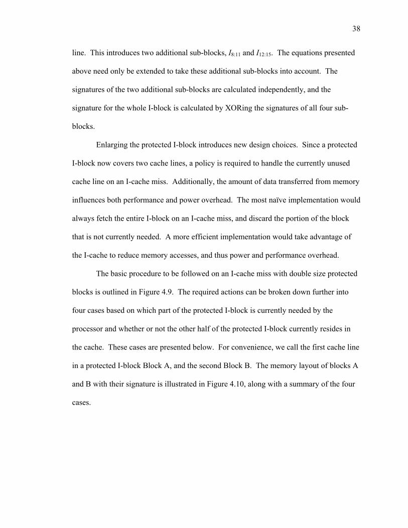
38
line. This introduces two additional sub-blocks, I8:11 and I12:15. The equations presented
above need only be extended to take these additional sub-blocks into account. The
signatures of the two additional sub-blocks are calculated independently, and the
signature for the whole I-block is calculated by XORing the signatures of all four sub-
blocks.
Enlarging the protected I-block introduces new design choices. Since a protected
I-block now covers two cache lines, a policy is required to handle the currently unused
cache line on an I-cache miss. Additionally, the amount of data transferred from memory
influences both performance and power overhead. The most naïve implementation would
always fetch the entire I-block on an I-cache miss, and discard the portion of the block
that is not currently needed. A more efficient implementation would take advantage of
the I-cache to reduce memory accesses, and thus power and performance overhead.
The basic procedure to be followed on an I-cache miss with double size protected
blocks is outlined in Figure 4.9. The required actions can be broken down further into
four cases based on which part of the protected I-block is currently needed by the
processor and whether or not the other half of the protected I-block currently resides in
the cache. These cases are presented below. For convenience, we call the first cache line
in a protected I-block Block A, and the second Block B. The memory layout of blocks A
and B with their signature is illustrated in Figure 4.10, along with a summary of the four
cases.

39
Figure 4.9 I-Cache Miss Algorithm, PMAC Implementation, Expanded Protected I-Block
Sub-block 0Sub-block 1Sub-block 2Sub-block 3
Signature
Block A
Block B
Block A in cache
Block A not in cache
Block B in cache
Block B not in cache
Condition
4
1Block A
3Block B
2
Case #Miss On
Block A in cache
Block A not in cache
Block B in cache
Block B not in cache
Condition
4
1Block A
3Block B
2
Case #Miss On
Figure 4.10 Memory Layout and Cache Miss Cases
1. Probe I-cache for desired block. If found, return, otherwise continue.
2. Initiate fetch of instruction block and signature from memory.
3. Start cryptographic calculations using KEY1 on instruction sub-block addresses (see Equation (4.6)).
4. If SICM, start cryptographic calculations using KEY3 on instruction sub-block and signature addresses; decrypt instruction blocks and signature once available (see Equations (4.4) and (4.5)).
5. Calculate signatures for each instruction block (see Equations (4.6) and (4.7)).
6. Calculate total signature by XORing instruction block signatures.
7. Compare calculated signature to signature fetched from memory. If mismatch, trap to operating system.

40
4.3.3.1 Miss on Block A
The first case involves an I-cache miss on Block A, with Block B not present in
the I-cache. The second case also involves a miss on Block A, but with Block B
available in the cache. In the first case, both Block A and Block B must be fetched from
memory, followed by the signature. This can be done with one bus cycle. In the second
case, Block A and the signature must be fetched from memory, while Block B could be
read from the cache. However, in most systems this would involve two bus cycles, one
to fetch Block A and another to fetch Block B. Each bus cycle incurs a significant
latency before the first chunk of data is available. For most architectures, this latency is
greater than the time required to transfer Block B during a continuous bus cycle. In our
example architecture, this latency is 12 clock cycles, as opposed to 8 clock cycles for
continuing to fetch Block B along with Block A and the signature. In the first case, both
blocks are put into the I-cache; this is a form of prefetching which may improve
performance for many applications. In the second case, only Block A should be put into
the cache and IVB.
The latency introduced in these two cases is illustrated in Figure 4.11. Since only
Block A is needed immediately, the processor can resume execution once Block A has
been completely fetched from memory. Verification for the whole protected I-block will
be complete 21 cycles later. Note that since both cases result in fetching Block B, the
extra cache hit latency incurred when probing the cache for Block B may be overlapped
with the memory access latency.

41
0 2 4 6 8 10 12 14 16 18 20 22 24 26 28 30 32 34 36 38Time (clock cycles)
Memorypipeline
Cryptopipeline
SP(A(SB0 ))
S
cS
Verification Latency
SP(A(SB2 ))SP(A(SB1 ))
I0:1 I2:3 I4:5 I6:7 S0:1 S2:3I8:9 I10:11 I12:13 I14:15
= ?
SP(A(SB3 ))
Figure 4.11 Verification Latency, PMAC RbV Implementation, Expanded Protected I-Block, Cases 1 and 2
4.3.3.2 Miss on Block B
The third case involves an I-cache miss on Block B where Block A is not present
in the cache. As with the first two cases, the entire protected I-block must be fetched
from memory. Block A and Block B are both cached, and Block B’s instructions are put
into the IVB. The verification latency of this case is illustrated in Figure 4.12. The
processor may resume execution once Block B is available, which is 8 clock cycles later
than in the first two cases. Verification is complete after 13 additional clock cycles. This
case would incur an additional cache hit latency due to probing the cache for Block A.
This latency is not shown in the figure.

42
0 2 4 6 8 10 12 14 16 18 20 22 24 26 28 30 32 34 36 38Time (clock cycles)
Memorypipeline
Cryptopipeline
SP(A(SB0 ))
SP(A(SB3 ))
S
cS
Verification Latency
SP(A(SB2 ))SP(A(SB1 ))
I0:1 I2:3 I4:5 I6:7 S0:1 S2:3I8:9 I10:11 I12:13 I14:15
= ?
Figure 4.12 Verification Latency, PMAC RbV Implementation, Expanded Protected I-Block, Case 3
The fourth and final case involves an I-cache miss on Block B where Block A is
available in the cache. In this situation, Block B and the signature are fetched from
memory while Block A is retrieved from the cache. The verification latency in this case
is illustrated in Figure 4.13. Execution may resume once Block B is available, and
verification is complete 13 cycles later. This case also incurs an additional cache hit
latency due to probing the cache for Block A. Again, this latency is not shown in the
figure.
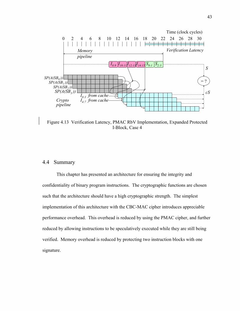
43
0 2 4 6 8 10 12 14 16 18 20 22 24 26 28 30Time (clock cycles)
Memorypipeline
Cryptopipeline
S
cS
Verification Latency
S0:1 S2:3I8:9 I10:11 I12:13 I14:15
= ?
I0:3 from cacheI4:7 from cache
SP(A(SB0 ))
SP(A(SB2 ))SP(A(SB3 ))
SP(A(SB1 ))
Figure 4.13 Verification Latency, PMAC RbV Implementation, Expanded Protected I-Block, Case 4
4.4 Summary
This chapter has presented an architecture for ensuring the integrity and
confidentiality of binary program instructions. The cryptographic functions are chosen
such that the architecture should have a high cryptographic strength. The simplest
implementation of this architecture with the CBC-MAC cipher introduces appreciable
performance overhead. This overhead is reduced by using the PMAC cipher, and further
reduced by allowing instructions to be speculatively executed while they are still being
verified. Memory overhead is reduced by protecting two instruction blocks with one
signature.
44
CHAPTER 5
HARDWARE SUPPORTED TECHNIQUES FOR ENSURING DATA INTEGRITY AND CONFIDENTIALITY
In this chapter, we discuss the proposed architecture for protecting the integrity
and confidentiality of data. It is presented as an extension of the instruction architecture,
so familiarity with the material from the previous chapter is assumed. We begin with an
overview of the proposed architectural extensions, followed by detailed descriptions. We
then examine the hardware needed to implement this protection and discuss the overhead
incurred from this architecture.
5.1 Data Framework Overview
Adding protection for data requires modifications to all three stages of the
architectural framework. As with instructions, three levels of data protection are
possible. The first is unprotected, in which neither the integrity nor the confidentiality of
data is ensured. The second is data integrity only mode (DIOM), in which data are stored
as plaintext but their integrity is assured. The last is data integrity and confidentiality
mode (DICM), which additionally encrypts data to ensure their confidentiality. These
modes may be implemented alongside any of the instruction modes (unprotected, SIOM,
or SICM) as desired.

45
The integrity of instructions is protected using signatures crafted to protect against
spoofing and splicing attacks. This scheme works well for protecting static data that
never change, such as instructions and constant data values. Therefore, static data blocks
can be protected using the same procedures that protect instructions. Dynamic data that
can be programmatically changed are further subject to replay attacks. Therefore, a
versioning scheme is required to ensure that all fetched dynamic data is up-to-date.
Versioning is implemented on the level of a protected data block. As before, the
line size of the lowest level data cache (D-cache) is the most convenient protected block
size. Each protected data block will have an associated sequence number. Sequence
numbers are stored in a table elsewhere in memory. The sequence number must be
included in the formula for the data block signature to protect against replay attacks.
Unlike data blocks, sequence numbers need not be encrypted to ensure data
confidentiality [20].
A sophisticated replay attack could conceivably replay sequence numbers as well
as data blocks. Therefore, the sequence numbers themselves must be protected against
replay attacks. To that end, the sequence number table for a given page is treated as a
collection of data blocks, and signatures are calculated for each block. These signatures
are then XORed together to form the page root signature. Page root signatures are stored
in a table somewhere in memory, likely near the existing page table.
A final signature is needed to protect the integrity of the page root signatures.
This program root signature is calculated by XORing all the page root signatures
together. This signature is never to be stored in main memory, and should never leave
the processor as plaintext.
46
5.1.1 Secure Installation
Secure installation must insert signatures for data blocks residing in static data
pages. These signatures are calculated in the same manner as instruction signatures. We
again assume a sign, then encrypt implementation of our architecture with the PMAC
cipher on the 32-bit example architecture with 32 byte protected blocks. As with
instruction blocks, the data block is divided into two sub-blocks of equal size, D0:3 and
D4:7. Let A(SBi) be the starting virtual address of sub-block i, SP represent a secure
padding function, and KEY1 and KEY2 be the first two of the aforementioned unique
program keys. We calculate a signature Sig(SBi) for each sub-block i according to
Equation (5.1). These sub-block signatures are then XORed together to produce the
block signature S, as in Equation (5.2). Each signature is stored immediately following
the data block that it protects.
( )[ ] ,1..0,))(()()( 134:42 == + iSBASPAESxorDAESSBSig iKEYiiKEYi (5.1)
.)()( 10 SBSigxorSBSigS = (5.2)
If data confidentiality is desired, then the data block and signature must be
encrypted before storage. The ciphertext sub-blocks C0:3 and C4:7, are calculated
according to Equation (5.3). The encrypted signature eS is calculated according to
Equation (5.4). The encrypted sub-blocks and signatures are then stored.
( ) ,1..0,))(()()( 334:434:4 == ++ iSBASPAESxorDC iKEYiiii (5.3)
( ).))((3 eSASPAESxorSeS KEY= (5.4)

47
5.1.2 Secure Loading
The secure loading procedure must be modified to reset the program root
signature in a special register on-chip. Since this signature is calculated from the page
root signatures of dynamic data pages, it is as yet undefined at load time. On a context
switch, the signature must be re-encrypted and stored in the process control block. It
should never leave the processor in plaintext.
5.1.3 Secure Execution
The data protection architecture requires several modifications to the secure
execution phase. We begin by examining the required behavior on translation lookaside
buffer (TLB) events. We then describe how secure structures for dynamic data pages are
established on or after page allocation, and how these structures are used in relation to
data caches. Finally, we discuss how this architecture deals with sequence numbers.
5.1.3.1 Page Allocation
The secure structures required for the data protection architecture must be
prepared for each dynamic data page that is allocated. First, its sequence number blocks
must be initialized and used to calculate the initial page root signature. The sequence
blocks and the page root signature must be written to memory in their appropriate
reserved areas. The starting address or offset from a known starting address for the
page’s sequence number blocks must be added to the page’s entry in the page table.
Secondly, the signatures for the page’s data blocks must be calculated and stored in
memory.

48
One option for implementing these procedures is to assume that the operating
system is trusted and allow it to perform the necessary operations on memory allocation.
This could potentially introduce high overhead. The other option is to perform the
operations in hardware and provide an instruction allowing the OS to trigger them. We
choose the latter option for both procedures.
Sequence number blocks must be initialized and used to calculate the page root
signature before the allocated page can be used. We assume a page size of four kilobytes
for our example architecture. Each page can contain 85 data blocks with their 16 byte
signatures, with 16 bytes of padding required at the end of the page. We define our
sequence numbers to be two bytes long. Thus, a total of six 32 byte blocks is required,
with less than half of the last block actually used. As mentioned earlier, these blocks are
stored in a reserved location in memory.
The page root signature for the new dynamic page must be calculated from the
page’s sequence number blocks. Each sequence number block is divided into two sub-
blocks, SQ0:3 and SQ4:7, and their signatures calculated according to Equation (5.5). The
signatures of each sub-block are XORed together to form the page root signature. Note
that the latter half of the sixth sequence number block in each page is not used; it may be
omitted from page root signature calculation. Once calculated, the page root signature is
stored in the page root signature table. The index of the page root signature in the table is
stored in the page table.
( )[ ] .1..0,))(()()( 134:42 == + iSBASPAESxorSQAESSBSig iKEYiiKEYi (5.5)

49
The program root signature is calculated from the page root signatures. It is
calculated by XORing the page root signatures of dynamic data pages. Thus, when a new
dynamic data page is allocated, the program root signature must be updated by XORing it
with the newly calculated page root signature. All calculations on the program root
signature must be performed on-chip. As stated earlier, it must never leave the CPU in
plaintext form. It must be encrypted using the processor’s secret key, Key.CPU, before
being brought off-chip during a context switch.
The other task required for new dynamic data pages is data block signature
initialization. This could be done on page allocation, but that could introduce significant
overhead. Instead, we propose to create the signatures on the block’s first write-back. A
block initialization bit vector must be established with a bit for each data block in the new
page. This bit vector specifies which data blocks in the page have been used. Each block
is initially marked as unused. The block initialization bit vector is stored in the page
table.
The memory structures described above are summarized in Figure 5.1. Part (a) of
this table shows a protected dynamic data page with signatures and page padding. Part
(b) shows the new fields required in the page table. The first field specifies whether this
page contains static data or dynamic data. The second field is the block initialization
vector. The third field is a pointer to the page’s root signature in the page root signature
table (part (c) in the figure). The final field is a pointer to the first sequence number
block for the page (part (d) in the figure). Note that the TLB must also be expanded to
include these data.

50
Data Block 0
Page Padding
Signature 0
Data Block 1
Signature 1
Data Block 84
Signature 84
...
S/D? Seq Num PointerPage Root Sig Offset
Seq Num Block 1
Seq Num Block 2
Seq Num Block 3
Seq Num Block 4
Seq Num Block 5
Seq Num Block 6Page Root Sig
(a)
(b)
(c) (d)
Block Init. Vector
Figure 5.1 Memory Structures for Protecting Dynamic Data: (a) Dynamic Data Page, (b) Page Table Modifications, (c) Page Root Signature Table, (d) Sequence Number
Table
5.1.3.2 TLB Miss and Write-back
On a TLB miss, information about a data page is brought into the TLB. If the
page in question is a dynamic data page, the extra data required by this architecture must
be loaded from the page table and stored in the TLB at this point: a bit specifying
whether this page is static or dynamic, the starting address (or offset from a known
starting address) of the page’s sequence number blocks, the index of the page root
signature associated with this page, and the page’s block initialization bit vector. The
integrity of the page root signatures is also verified at this point. The signatures from
every active data page are retrieved from the TLB or from memory. These signatures are
XORed together to recalculate the current program root signature. If the calculated
program root signature does not match that stored on-chip, then the page root signatures
have been subjected to tampering and a trap to the operating system is asserted.
51
A page root signature will be updated when the sequence number for a data block
within that page is incremented. The program root signature will also be updated at that
time. See Section 5.1.3.5 below for discussion on the handling of sequence numbers.
Thus the only action required upon a TLB write-back is to write the page root signature
and block initialization bit vector contained in the TLB entry being evicted to memory.
5.1.3.3 Data Cache Miss
Data block verification is performed on data cache read misses and write misses
on blocks that have already been used. Therefore, on a write miss the first task is to
check the block’s entry in the block initialization bit vector in the TLB. If the block has
not yet been used then no memory access is required. The cache block is simply loaded
with all zeros, preventing malicious data from being injected at this point.
If the miss was a read miss or a write miss on a previously used block, then the
data block must be fetched and verified. The signatures of the sub-blocks D0:3 and D4:7
fetched from memory are calculated in the same manner as static data sub-blocks
according to Equation (5.1). If the block is in a dynamic page, the sequence number SN j
must be fetched and encrypted (Equation (5.6)) before the signature cS of the entire block
may be calculated (Equation (5.7)). Therefore, fetching the sequence number is in the
critical path of data verification. The handling of sequence numbers is discussed below
in Section 5.1.3.5. As with the instruction architecture described above, the simplest
implementation stalls the processor until data block verification is complete. We assume
this simple implementation throughout the rest of the paper as speculatively using the
data would introduce somewhat more complex hardware requirements than are

52
introduced by allowing the processor to execute newly fetched instructions before they
are verified.
,))((1* j
KEYj SNSPAESSN = (5.6)
.)()( *10
jSNxorSBSigxorSBSigcS = (5.7)
If the architecture is running in DICM mode, then the fetched data must be
decrypted. In this case, ciphertext sub-blocks C0:3 and C4:7 are fetched from memory, and
the plaintext data sub-blocks D0:3 and D4:7 are calculated according to Equation (5.8).
The encrypted signature eS fetched from memory must also be decrypted according to
Equation (5.9). As with encrypted instructions, the necessary encryption operations may
be computed in parallel with memory access, so fetched data blocks can be decrypted via
a simple XOR operation as soon as both the necessary cryptographic operation is
complete and the data sub-block is available from memory.
( ) ,1..0,))(()()( 334:434:4 == ++ iSBASPAESxorCD iKEYiiii (5.8)
( ).))((3 eSASPAESxoreSS KEY= (5.9)
5.1.3.4 Data Cache Write-back
The data cache write-back procedure must be modified to support integrity and
confidentiality. When a dirty data block from a dynamic data page is chosen for eviction,
the signatures of its sub-blocks are calculated according to Equation (5.1). The sequence
number must be also be updated. The current sequence number SN j must be fetched and
incremented according to Equation (5.10). The new sequence number SN (j+1) is then

53
encrypted as described in Equation (5.11), and used to calculate the new signature for the
total data block as in Equation (5.12). Again, the sequence number is on the critical path
for signature generation, and must be handled appropriately. At this point, the page root
signature must also be updated. The signature of the appropriate sequence number sub-
block must be calculated prior to the sequence number increment. This signature is then
XORed with the page root signature contained in the TLB, effectively subtracting it out
of the signature. A similar procedure is followed to update the program root signature
using the old and new page root signatures. The signature of the sequence number sub-
block after the increment is also calculated and XORed with the page root signature,
which is stored back in the TLB.
,1)1( +=+ jj SNSN (5.10)
,))](( )1(1
*)1( ++ = jKEY
j SNSPAESSN (5.11)
.)()( )*1(10
+= jSNxorSBSigxorSBSigS (5.12)
If data confidentiality is not being protected, then the data block and its new
signature S are then put into the write buffer. If confidentiality is required, then the
encrypted data block C and encrypted signature cS are calculated according to
Equations (5.13) and (5.14). The encrypted block and signature are then put in the write
buffer.
( ) ,1..0,))(()()( 334:434:4 == ++ iSBASPAESxorDC iKEYiiii (5.13)
( ).))((3 eSASPAESxorSeS KEY= (5.14)

54
5.1.3.5 Handling Sequence Numbers
Since sequence numbers are on the critical path for both data cache misses and
write-backs, efficient handling of sequence numbers is imperative to keep performance
overhead low. Thus we cache sequence numbers on-chip, preventing extra memory
accesses on each data cache miss or write-back. This caching will be further elaborated
in Section 5.3.2 below.
Whenever the required sequence number is not found in the sequence number
cache, it must be fetched from memory. At this point, the integrity of the sequence
numbers for the data page in question must be verified. This requires all six sequence
number blocks associated from the page. These blocks may be retrieved from the cache
or from memory as appropriate. The signatures for each sub-block of the sequence
number blocks are calculated according to Equation (5.5). As during page allocation, the
latter sub-block of the sixth sequence number block may be ignored. The signatures of
all the sub-blocks are XORed together to calculate the page root signature. This
recalculated page root signature is checked against that stored in the TLB. If they do not
match, then a trap to the operating system is asserted.
When sequence number blocks are evicted from the sequence number cache, no
cryptographic activity is required. Furthermore, the page root signature is updated during
data cache write-back, and will be written to memory during a TLB write-back.
5.2 Hardware Support for Runtime Verification
As with the instruction architecture, all three stages of the data architecture
require hardware support. The secure installation state machine must be modified to sign
static data blocks. A special-purpose register is required to hold the program root

55
signature. An instruction must be added to trigger a state machine to initialize sequence
number blocks and page root signatures. The data TLB must be enlarged such that each
entry can hold its corresponding page root signature, the address (or offset from a known
starting address) of the first sequence number block for that page, index of the
appropriate page root signature in the page root signature table, the page root signature
itself, and the page’s block initialization bit vector. It must also have a dirty bit
specifying whether or not the page root signature has changed and a bit specifying
whether the page is static or dynamic. The context switch operation must be modified to
write back any dirty page root signatures in the TLB.
The IBSVU must be modified to also serve as a generalized signature verification
unit (SVU). The most complex part of the SVU is still the AES cipher hardware. The
same pipelined PMAC cipher hardware used for instructions can also be used with the
data architecture. Address translation hardware and additional buffers for temporary
storage are also required in the SVU.
Sequence number retrieval is on the critical path for both data cache misses and
write-backs. These are the most common of the events described during secure
execution. Furthermore, sequence number verification requires all the sequence number
blocks corresponding to the page in question. We therefore propose that a dedicated on-
chip sequence number cache be used. When a sequence number is needed, it is first
sought in the sequence number cache. If it is not in that cache, then all sequence number
blocks not in the cache for that page must be fetched. The integrity of the sequence
numbers will then be verified and the newly fetched sequence number blocks stored in

56
the sequence number cache. Using the sequence number cache requires an increase in
cache budget, but should keep performance overhead low.
5.3 Performance Overhead
In this section, we analyze the overhead introduced by the proposed architecture
for data integrity and confidentiality during secure execution. We start with TLB events,
which occur the least frequently of the events required by the architecture, but potentially
introduce the greatest overhead. We then address sequence number cache events, which
are more frequent. We finally look at data cache events, which are the most frequent of
all defined events in this architecture. These discussions assume the example system
discussed above with the PMAC cipher.
5.3.1 TLB Miss and Write-back
The overhead introduced by the architecture on a TLB miss depends on the
number of protected data pages at the time of the miss. It also depends on design choices
made when implementing the architecture. The page root signatures for every protected
data page are required. Signatures currently residing in the TLB should be used, as the
data in memory might be stale. All signatures not currently in the TLB must be fetched
from memory.
This situation leads to a design choice. Consider the case where the TLB contains
a noncontiguous subset of the total page root signature table. In some memory
architectures, fetching only the signatures not currently in the TLB would introduce
greater memory overhead than simply fetching all signatures and ignoring those already
in the TLB. This is due to the longer latencies introduced by starting new memory
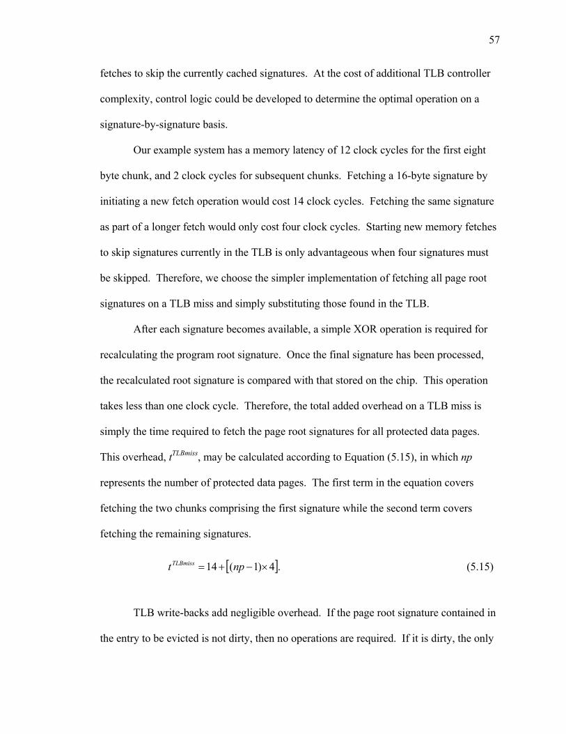
57
fetches to skip the currently cached signatures. At the cost of additional TLB controller
complexity, control logic could be developed to determine the optimal operation on a
signature-by-signature basis.
Our example system has a memory latency of 12 clock cycles for the first eight
byte chunk, and 2 clock cycles for subsequent chunks. Fetching a 16-byte signature by
initiating a new fetch operation would cost 14 clock cycles. Fetching the same signature
as part of a longer fetch would only cost four clock cycles. Starting new memory fetches
to skip signatures currently in the TLB is only advantageous when four signatures must
be skipped. Therefore, we choose the simpler implementation of fetching all page root
signatures on a TLB miss and simply substituting those found in the TLB.
After each signature becomes available, a simple XOR operation is required for
recalculating the program root signature. Once the final signature has been processed,
the recalculated root signature is compared with that stored on the chip. This operation
takes less than one clock cycle. Therefore, the total added overhead on a TLB miss is
simply the time required to fetch the page root signatures for all protected data pages.
This overhead, tTLBmiss, may be calculated according to Equation (5.15), in which np
represents the number of protected data pages. The first term in the equation covers
fetching the two chunks comprising the first signature while the second term covers
fetching the remaining signatures.
[ ].4)1(14 ×−+= nptTLBmiss (5.15)
TLB write-backs add negligible overhead. If the page root signature contained in
the entry to be evicted is not dirty, then no operations are required. If it is dirty, the only

58
required operation is to place the appropriate page root signature and bit initialization
vector into the write buffer, which will independently write it to memory when the bus is
free.
5.3.2 Sequence Number Cache Miss and Write-back
The basic procedure to be followed on a sequence number cache miss is outlined
in Figure 5.2. We are presented with another design choice. On a sequence number
cache miss, the six sequence number blocks associated with the page that caused the miss
must be retrieved. Some of these may be already cached; the rest must be fetched from
memory. As with the TLB miss handling scheme, the implementation must balance
overhead versus complexity. For our sample implementation, we choose a scheme of
moderate complexity. On a sequence number cache miss, the sequence number cache is
probed for the page’s first sequence number block. If it is found in the cache, the cache is
probed for the next block and so forth until a block is not found in the cache. A memory
fetch is initiated for that block, and further probing for the rest of the blocks occurs in
parallel. All blocks between and including the first not found in the cache to the last not
found in the cache are fetched from memory. Any fetched blocks that were found in the
sequence number cache are ignored, and the blocks that were not previously cached are
inserted in the cache.

59
Figure 5.2 Sequence Number Cache Miss Algorithm
The necessary cryptographic operations for regenerating the root page signature
are started at the same time as the first cache probe. In most cases, the final
cryptographic operation can be started when the last chunk of data is read from memory.
The number of clock cycles required to handle a sequence number cache miss, tSNmiss, can
be calculated from Equation (5.16). In this equation, bα is the number of the first block to
be fetched (from one to six), and bω is the number of the last block to be fetched. The
first term represents the overhead induced by the initial probes before the first fetch. The
second and third terms show the number of clock cycles required to fetch the first and
subsequent data blocks, respectively. The final term indicates that the final cryptographic
operation begins after the memory fetch is completed, and includes a clock cycle for
signature comparison.
1. Probe seqnum cache for desired sequence number block. If found, return, otherwise continue.
2. Probe seqnum cache for page’s first sequence number block. Continue probing until a block is not found.
3. Initiate fetch of first sequence number block that was not found, keep probing for other blocks in parallel and schedule appropriate memory fetches.
4. Start cryptographic calculations using KEY1 for all sequence number sub-block addresses (see Equation (5.5)).
5. Calculate signature for sub-blocks (see Equation (5.5)).
6. XOR sub-block signatures together to calculate page root signature.
7. Compare calculated page root signature to that in TLB. If mismatch, trap to operating system.

60
( ) .,13818 ωααωα bbbbbt SNmiss ≤+−++= (5.16)
Our architecture does have a few exceptions to this equation. The first exception
is when only the first sequence number block must be fetched. In this case, the probing
and memory operations are complete before all necessary cryptographic operations can
be started, leading to an additional delay of two clock cycles. A similar issue exists when
only the second block must be fetched; this case requires one additional clock cycle.
Furthermore, for simplicity’s sake, the equation above assumes that the entire sixth block
will be fetched. Since only the first half of the sixth block is used, the second half does
not contribute to the page root signature and need not be fetched. Thus when the sixth
block is fetched, four fewer clock cycles are required.
Sequence number cache write-backs introduce negligible overhead. As with TLB
write-backs, no cryptographic operations are required. The sequence number block being
evicted only needs to be placed in the write buffer to be written to memory when the bus
is available.
5.3.3 Data Cache Miss
The first task that must be performed on a data cache miss is to request the
appropriate sequence number from the sequence number cache. In our sample system,
this takes only one clock cycle on a sequence number cache hit, and between 33 and
67 clock cycles on a miss. Once the sequence number is available, the necessary
cryptographic operations and memory access can begin in parallel. The procedures to be
followed on a D-cache miss are outlined in Figure 5.3. The verification latency from the
time the sequence number is available to the time when the processor can continue
execution is illustrated in Figure 5.4. As in the verification latency figures from

61
Chapter 4, the darkly shaded boxes in the crypto pipeline section indicate cryptographic
operations required before signature calculation begins. The lighter shaded boxes
indicate actual signature calculation operations. This figure assumes DIOM mode for
brevity; DICM would not introduce any additional latency as it only requires two
additional cryptographic operations prior to starting signature generation. This would
shift the start of signature generation for the first block by one clock cycle, but would not
affect the overall latency. As the figure shows, signature verification is complete after
31 clock cycles, at which time the processor may continue and use the fetched data.
This architecture may be optimized further, beyond the aforementioned possibility
of using fetched data while it is still being verified. For instance, the memory operation
for fetching the data could be initiated as soon as the last sequence number block is
fetched on a sequence number cache miss. The necessary cryptographic operations may
also start as soon as possible, even while the sequence number verification operations are
ongoing. These optimizations are not explored here, but would be a potential area for
future research.

62
Figure 5.3 D-Cache Miss Algorithm
0 2 4 6 8 10 12 14 16 18 20 22 24 26 28 30Time (clock cycles after sequence number is available)
Memorypipeline
Cryptopipeline
SP(A(SB0 ))SP(A(SB1 ))
S
cS
Verification Latency
D0:1 D2:3 D4:5 D6:7 S0:1 S2:3
= ?
SP(SN j )
Figure 5.4 Verification Latency, D-Cache Miss
1. Probe D-cache for desired block. If found, return, otherwise continue.
2. Request sequence number block from seqnum cache. Wait until sequence number is available.
3. Initiate fetch of data block and signature from memory.
4. Start cryptographic calculations using KEY1 on data sub-block addresses and the sequence number (see Equations (5.1) and (5.6)).
5. If DICM, start cryptographic calculations using KEY3 on data sub-block addresses; decrypt data block when available (see Equations (5.8) and (5.9)).
6. Calculate signature for data block (see Equations (5.1), (5.6), and (5.7)).
7. Compare calculated signature to signature fetched from memory. If mismatch, trap to operating system.

63
5.3.4 Data Cache Write-back
The sequence number is also required on a data cache write-back. Again, the first
operation should be to request the sequence number. Once it is available, cryptographic
operations can begin. The procedure to be followed is outlined in Figure 5.5. Once the
operations supporting signature sub-block updates are complete, the page root signature
in the TLB may be updated in parallel with the ongoing data block signature calculation.
The program root signature must also be updated along with the page root signature. A
total of 8 cryptographic operations is required in DIOM mode, yielding a total latency of
19 clock cycles. DICM mode requires an additional three cryptographic operations to
support data block and signature encryption, leading to a total latency of 22 clock cycles.

64
Figure 5.5 D-Cache Write-back Algorithm
5.4 Summary
An architecture for protecting integrity and confidentiality has been presented in
this chapter. It builds on the previous chapter’s instruction protection architecture,
inheriting its cryptographic strength. Static data is protected with the same low overhead
introduced by the instruction protection architecture. Dynamic data are further protected
by implementing a versioning scheme using sequence numbers to prevent replay attacks.
The increased overhead is alleviated by caching the sequence numbers.
1. Request sequence number block from seqnum cache. Wait until sequence number is available.
2. Increment sequence number while buffering original sequence number sub-block (see Equation (5.10)).
3. Start cryptographic calculations using KEY1 on sequence number, sequence number sub-block address, and data sub-block addresses (see Equations (5.1) and (5.11)).
4. Calculate signature for original and updated sequence number sub-blocks (see Equation (5.1)).
5. XOR program root signature with page root signature in TLB.
6. XOR page root signature in TLB with original sequence number sub-block signature.
7. XOR page root signature in TLB with updated sequence number sub-block signature.
8. XOR program root signature with new page root signature in TLB.
9. Calculate signature for data block (see Equations (5.1) and (5.12)).
10. If DICM, start cryptographic calculations using KEY3 on data sub-block and signature addresses XORed with updated sequence number; encrypt data block and signature when ready (see Equations (5.13) and (5.14)).
11. Place data block and signature in write buffer.

65
CHAPTER 6
EXPERIMENTAL ENVIRONMENT
Cycle-accurate simulation software was used to evaluate the overhead of our
proposed architectural enhancements. This simulator performs functional simulation of
the instruction protection architecture, but only a timing simulation of the data protection
architecture. This chapter describes the methodology used in this evaluation. We start
with an overview of the experimental flow, then discuss the benchmark applications that
are chosen for simulation. We finally discuss the simulator itself, and the simulation
parameters used in our evaluation runs.
6.1 Experimental Flow
The experimental flow for evaluating our proposed architectures is illustrated in
Figure 6.1. We start with uncompiled source code for benchmark applications of interest,
which are described in Section 6.2 below. These are compiled using a cross-compiler to
generate executable binaries in the standard Executable and Linkable Format (ELF) [42].
The cross-compiler encodes the executables for the ARM instruction set. These binaries
may then be run in the simulator under a baseline configuration without security
enhancements. The simulator mimics an embedded microprocessor based on the ARM
architecture. With the appropriate inputs, it analyzes both execution time and power

66
BenchmarkSource Code
ARMCross Compiler
BinaryExecutable
Secure InstallationEmulator
Secure BinaryExecutable
SimulatorBenchmarkInputs
ArchitecturalParameters
Results
Simulator Baseline ArchitecturalParameters
Benchmark Inputs
BaselineResults
Figure 6.1 Experimental Flow
consumption for the baseline configuration. This simulator is described more thoroughly
in Section 6.3.
The cross-compiled executables are processed through a program that emulates
the secure installation process to produce secure executables. This secure installation
emulator is based on the one described in [4], but has been updated to insert instruction
signatures directly after the instruction blocks they protect. The secure installation
procedures for protecting data are not emulated since the simulator only performs a
timing analysis for the data architecture.
The secure benchmark executables can then be run in the simulator. The
simulator is configured to model the aforementioned ARM-based embedded processor

67
enhanced with the instruction and/or data protection architectures proposed in Chapters 3
and 4. It analyzes the execution time of the benchmarks for both architectures. It also
analyzes the power overhead for the instruction protection architecture. Once simulation
runs are completed, the relevant results can be mined from the simulator outputs.
6.2 Benchmarks
Two sets of benchmarks are selected for evaluating the overhead of the proposed
architectures. The first set of benchmarks represents typical tasks that an embedded
system might perform. These benchmarks are described in Table 6.1, which lists the
name, description, and total number of executed instructions for each of the embedded
benchmarks. They are selected from among the benchmark suites MiBench [43],
MediaBench [44], and Basicrypt [45]. The primary criteria for selecting these
benchmarks are the cache miss rates. In order to properly exercise the proposed
architectures, high miss rates for at least one of the cache sizes to be simulated are
desired. Thus, these benchmarks often represent a worst-case scenario with the greatest
possible overhead; other benchmarks with very low cache miss rates would only show
negligible overhead. The embedded benchmarks’ cache miss rates when simulated on a
baseline architecture for various cache sizes of interest are shown in Table 6.2.

68
Table 6.1 Description of Embedded Benchmarks
Benchmark Description Executed Instructions [106]
blowfish_enc Blowfish encryption 544.0
cjpeg JPEG compression 104.6
djpeg JPEG decompression 23.4
ecdhb Diffie-Hellman key exchange 122.5
ecelgencb El-Gamal encryption 180.2
ispell Spell checker 817.7
mpeg2_enc MPEG2 compression 127.5
rijndael_enc Rijndael encryption 307.9
stringsearch String search 3.7
Table 6.2 Cache Miss Rates for Embedded Benchmarks
Benchmark Instruction Cache Misses per 1000 Executed Instructions
Data Cache Misses per 1000 Executed Instructions
1 KB 2 KB 4 KB 8 KB 1 KB 2 KB 4 KB 8 KB
blowfish_enc 33.8 5.1 0 0 63.5 43.4 8.4 0.3
cjpeg 7.6 1.3 0.3 0.1 92.5 69.8 56.9 8.9
djpeg 11.9 5.5 1.3 0.3 88 54.3 34.8 13.4
ecdhb 28.5 8.5 2.9 0.1 5.7 1.2 0.3 0.2
ecelgencb 25.4 4.5 1.4 0.1 3 0.7 0.2 0.1
ispell 72.4 53 18.8 2.9 60.4 33.4 4.3 1.5
mpeg2_enc 2.2 1.1 0.4 0.2 54.6 30.2 6.7 1.7
rijndael_enc 110.2 108.3 69.5 10.3 227.5 190.9 111.5 15.2
stringsearch 57.7 35 6.2 2.4 87.6 43 7.3 4.3

69
The second set of benchmarks represent tasks that are more suited to general
purpose computers rather than embedded systems. These benchmarks are selected from
the Standard Performance Evaluation Corporation (SPEC) 2000 benchmark suite [46].
SPEC benchmarks have much longer runtimes than the selected embedded benchmarks;
therefore, these benchmarks are selected so they could be simulated in a reasonable
timeframe (weeks rather than months) without placing undue strain on available
computing resources. Furthermore, only specific segments of the benchmarks are chosen
for detailed simulation. The SimPoint tool [47] is used to calculate the segments, which
are weighted such that metrics of interest may be measured for each segment, multiplied
by the appropriate weights, and the products summed to produce metrics that represent
the overall behavior of the benchmarks. Individual segments are executed by running the
benchmark program in a low-fidelity simulator for an offset of a certain number of
instructions, and then executing one hundred million instructions using the full simulator.
The selected SPEC benchmarks are described in Table 6.3, along with their
segment offsets. The weights for the various segments are presented in Table 6.4. The
overall cache miss rates (after weighting) for the benchmarks simulated with a baseline
system configuration are shown in Table 6.5. These benchmarks are run on simulated
systems with larger caches than the embedded benchmarks. Note that most of these
benchmarks have very few instruction cache misses, which should lead to a low overhead
for instruction protection. They do, however, exhibit appreciable data cache miss rates,
which makes them useful for observing the overhead introduced by data protection.
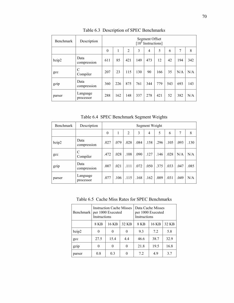
70
Table 6.3 Description of SPEC Benchmarks
Benchmark Description Segment Offset [108 Instructions]
0 1 2 3 4 5 6 7 8
bzip2 Data compression 611 85 421 149 473 12 42 194 342
gcc C Compiler 207 23 115 130 90 166 35 N/A N/A
gzip Data compression 360 226 875 761 344 779 543 693 143
parser Language processor 288 162 148 337 278 421 52 382 N/A
Table 6.4 SPEC Benchmark Segment Weights
Benchmark Description Segment Weight
0 1 2 3 4 5 6 7 8
bzip2 Data compression .027 .079 .028 .084 .158 .296 .105 .093 .130
gcc C Compiler .472 .028 .108 .090 .127 .146 .028 N/A N/A
gzip Data compression .007 .021 .111 .072 .050 .375 .033 .047 .085
parser Language processor .077 .106 .115 .168 .162 .009 .031 .049 N/A
Table 6.5 Cache Miss Rates for SPEC Benchmarks
Benchmark Instruction Cache Missesper 1000 Executed Instructions
Data Cache Misses per 1000 Executed Instructions
8 KB 16 KB 32 KB 8 KB 16 KB 32 KB
bzip2 0 0 0 9.3 7.2 5.8
gcc 27.5 15.4 4.4 46.6 38.7 32.9
gzip 0 0 0 21.8 19.5 16.8
parser 0.8 0.3 0 7.2 4.9 3.7
71
6.3 Simulation Software
The simulator used to evaluate the performance of the proposed architectures is a
derivative of the Sim-Panalyzer ARM simulator [48]. Sim-Panalyzer is itself an
extension of sim-outorder, the most detailed simulator from the SimpleScalar suite [49].
As before, we use the simulator modifications documented in [4] as the starting point for
our updates.
The simulator is updated to perform a full functional simulation of the instruction
protection architecture. This allows it to provide both a cycle-accurate timing analysis as
well as an estimate of the energy overhead. The largest update is the inclusion of the
instruction verification buffer, allowing instructions to execute in parallel with
verification. The instruction cache miss handler is modified to handle instruction
signatures located directly after the protected instruction blocks. It is also modified to
allow an individual signature to protect either one instruction block or two instruction
blocks. The energy overhead caused by the pipelined cryptographic hardware is
modeled as that caused by 57,000 gates of combinational logic [50].
The simulator is also updated to provide a partial functional simulation of the data
protection architecture. This only yields a cycle-accurate timing analysis; energy
overhead is not estimated. The most complex of the updates to support data protection is
the addition of a sequence number cache. This cache and its controller are fully
functional, although the sequence number data it handles are purely fictitious. The data
cache miss handler is modified to report the overhead that the data protection architecture
would incur. It queries the sequence number cache as appropriate, but only reports the
potential timing of all other operations. The data TLB handler is updated in a similar

72
manner. The simulator does not account for the overhead introduced by initializing
sequence number blocks on page allocation.
Performance overhead is analyzed by using the simulator to run the benchmark
programs described in Section 6.3. The SimpleScalar metric of interest for performance
overhead analysis is sim_cycle, the number of simulated clock cycles required for the
benchmark to run to completion. After simulation is complete, this value is mined from
the results and divided by the value of sim_cycle for appropriate baseline simulation
run, producing a normalized execution time value.
Energy overhead is also analyzed by running the benchmark programs in the
simulator. Only the energy overhead of the SICM architecture is analyzed, as a complete
functional DICM simulation is not implemented. The SimPAnalyzer metric of interest
for performance overhead analysis is uarch.pdissipation, the total power
dissipated by the simulated microarchitecture. As with the performance overhead metric,
this value is mined from simulation results and divided by the baseline microarchitecture
power dissipation, producing a normalized power dissipation value.
6.4 Simulation Parameters
The simulator is configured to simulate an ARM architecture running at
200 MHz. The I/O supply voltage is 3.3 V, with an internal logic power supply of 1 V.
All other power-related parameters correspond with a 0.18 μm process, and are obtained
from a template file provided with Sim-Panalyzer. All simulated systems are assumed to
have separate Level 1 instruction and data caches of the same size. This size varies
between 1 KB, 2 KB, 4 KB and 8 KB for the embedded benchmarks, and 8 KB, 16 KB,
and 32 KB for SPEC benchmarks. All cache line sizes are taken to be 32 bytes, as every

73
benchmark exhibited better performance on a baseline system with 32 byte cache lines
than with 64 byte lines. All caches use the least recently used (LRU) replacement policy,
For RbV implementations, instruction verification buffer depth is 16 unless otherwise
noted. Other architectural parameters used in the simulations are described in Table 6.6.
Table 6.6 Simulation Parameters
Simulator Parameter Value Branch predictor type Bimodal Branch predictor table size 128 entries, direct-mapped Return address stack size 8 entries Instruction decode bandwidth 1 instruction/cycle Instruction issue bandwidth 1 instruction/cycle Instruction commit bandwidth 1 instruction/cycle Pipeline with in-order issue True I-cache/D-cache 4-way, first level only I-TLB/D-TLB 32 entries, fully associative Execution units 1 floating point, 1 integer Memory fetch latency (first/other chunks) 12/2 cycles and 24/2 cycles Branch misprediction latency 2 cycles TLB latency 30 cycles AES latency 12 clock cycles Address translation (due to signatures) 1 clock cycle Signature comparison 1 clock cycle

74
CHAPTER 7
RESULTS
This chapter presents the results of both qualitative and quantitative analyses of
the proposed architectures for instruction and data protection. We start with qualitative
analyses of the complexity overhead required to implement our architectures on a
processor chip, followed by the extra space in memory required to run a secure program
on our architecture. We then present quantitative results from simulating the execution of
secure benchmark programs, focusing on performance and energy overhead.
7.1 Complexity Overhead
The hardware requirements for the instruction and data protection architectures
are discussed in Sections 4.2, 4.3, and 5.2. These architectures require state machines for
performing various tasks, logic for address translation, buffers and registers, hardware for
key generation, and a pipelined cryptographic unit. All but the last two of these
requirements introduce relatively little additional on-chip area. A physical unclonable
function (PUF) unit for key generation requires nearly 3,000 gates [24]. The pipelined
cryptographic unit, which is shared among both architectures, introduces the greatest
amount of overhead. Assuming that this cryptographic unit follows the commercially
available Cadence high performance 128-bit AES core [50], the on-chip area it requires
75
should be approximately equal to that required for 57,000 logic gates. An additional
source of complexity is the sequence number cache; its complexity is determined by its
size and organization, which are design parameters.
7.2 Memory Overhead
The memory overhead incurred by the instruction protection architecture is a
simple function of the protected block size and the number of instruction blocks in the
program. Each signature is 16 bytes long. If 32 byte protected blocks are chosen, then
the size of the executable segment of the program increases by 50%. This overhead is
reduced to 25% for 64 byte protected blocks, and to 12.5% for 128 byte protected blocks.
Data protection incurs overhead at different rates for pages containing constant
data and pages containing dynamic data. Constant data is protected like instructions, so
the memory overhead from protecting constant data blocks follows the figures given for
instruction blocks above. The memory overhead required for protecting dynamic data is
slightly larger. The data signatures lead to the same overhead figures as for static data
and instructions. However, each dynamic data page requires sequence number blocks,
additional space in the page table, and an entry in the page root signature table. The size
of the sequence number blocks is a design parameter; the sample architecture presented
in this paper requires 6 sequence number blocks of 32 bytes each, for a total sequence
number overhead of 192 bytes per protected dynamic page.
7.3 Instruction Protection Architecture (SICM) Overhead
This section presents qualitative analysis results for the instruction protection
architecture running in full SICM mode. We evaluate its performance and power

76
overhead, exploring the design space by varying cache sizes, cryptographic ciphers, and
implementation details. We also explore the optimum value for instruction verification
buffer depth.
7.3.1 Performance Overhead
The normalized execution times of the embedded benchmarks running in SICM
mode are plotted in Figure 7.1 and Figure 7.2, and expressed numerically in Table 7.1
and Table 7.2. Results are presented for Level 1 cache sizes of 1 KB, 2 KB, 4 KB, and
8 KB, and for the following implementations: CBC-MAC WtV, PMAC WtV, PMAC
RbV, and PMAC RbV with double-sized protected blocks and caching all fetched
I-blocks. These plots clearly show that, among the three normal-sized protected block
implementations, the PMAC RbV implementation incurs the lowest performance
overhead (negligible in most cases). They also indicate that double-sized protected
blocks can be used without incurring further overhead. In fact, some benchmarks exhibit
a speedup relative to baseline performance due to the prefetching behavior of caching all
fetched I-blocks.

77
1 KB L1 Caches
0.5
0.75
1
1.25
1.5
1.75
2
2.25
2.5
blowfis
h_en
ccjp
egdjp
egec
dhb
ecelg
encb
ispell
mpeg2e
nc
rijnda
el_en
c
string
searc
hTota
l
Nor
mal
ized
Exe
cutio
n Ti
me
CBC WtVPMAC WtVPMAC RbVPMAC RbV Double
2 KB L1 Caches
0.5
0.75
1
1.25
1.5
1.75
2
2.25
2.5
blowfis
h_en
ccjp
egdjp
egec
dhb
ecelg
encb
ispell
mpeg2e
nc
rijnda
el_en
c
string
searc
hTota
l
Nor
mal
ized
Exe
cutio
n Ti
me
CBC WtVPMAC WtVPMAC RbVPMAC RbV Double
Figure 7.1 Performance Overhead for Embedded Benchmarks, SICM, 1 KB and 2 KB L1 Cache Sizes

78
4 KB L1 Caches
0.5
0.75
1
1.25
1.5
1.75
2
2.25
2.5
blowfis
h_en
ccjp
egdjp
egec
dhb
ecelg
encb
ispell
mpeg2e
nc
rijnda
el_en
c
string
searc
hTota
l
Nor
mal
ized
Exe
cutio
n Ti
me
CBC WtVPMAC WtVPMAC RbVPMAC RbV Double
8 KB L1 Caches
0.5
0.75
1
1.25
1.5
1.75
2
2.25
2.5
blowfis
h_en
ccjp
egdjp
egec
dhb
ecelg
encb
ispell
mpeg2e
nc
rijnda
el_en
c
string
searc
hTota
l
Nor
mal
ized
Exe
cutio
n Ti
me
CBC WtVPMAC WtVPMAC RbVPMAC RbV Double
Figure 7.2 Performance Overhead for Embedded Benchmarks, SICM, 4 KB and 8 KB L1 Cache Sizes

79
Table 7.1 Performance Overhead for Embedded Benchmarks, SICM, 1 KB and 2 KB L1 Cache Sizes
Performance Overhead [%]
Benchmark CBC WtV
PMAC WtV
PMAC RBV
PMAC RBV
Double
1 KB 2 KB 1 KB 2 KB 1 KB 2 KB 1 KB 2 KB blowfish_enc 72.6 13.7 50.2 9.46 3.14 0.60 -12.3 -1.70 cjpeg 25.3 5.23 17.5 3.60 1.14 0.23 -1.52 0.35 djpeg 31.9 18.0 21.9 12.3 1.23 0.64 -2.51 -1.41 ecdhb 77.5 35.7 53.6 24.7 3.49 1.46 -12.0 -5.94 ecelgencb 68.8 18.8 47.6 13.0 3.14 0.77 -4.12 -3.10 ispell 99.8 88.5 68.8 60.9 4.31 4.03 -7.68 0.48 mpeg2enc 8.70 5.05 6.00 3.50 0.39 0.24 -0.58 -0.39 rijndael_enc 117.4 117.7 80.6 80.9 3.62 3.77 -14.2 -16.1 stringsearch 96.6 79.3 66.7 54.9 4.33 3.80 1.79 -2.03 Total 91.2 72.7 62.8 50.1 3.70 2.97 -9.37 -3.72
Table 7.2 Performance Overhead for Embedded Benchmarks, SICM, 4 KB and 8 KB L1 Cache Sizes
Performance Overhead [%]
Benchmark CBC WtV
PMAC WtV
PMAC RBV
PMAC RBV
Double
4 KB 8 KB 4 KB 8 KB 4 KB 8 KB 4 KB 8 KB blowfish_enc 0.17 0.00 0.14 0.00 0.09 0.00 0.06 -0.01 cjpeg 1.13 0.29 0.77 0.19 0.00 0.00 0.06 -0.00 djpeg 4.89 0.88 3.31 0.53 0.07 0.00 -0.21 -0.09 ecdhb 14.2 0.78 9.85 0.54 0.64 0.03 -1.96 -0.06 ecelgencb 6.58 0.34 4.55 0.24 0.30 0.01 -0.91 -0.04 ispell 49.7 10.4 34.3 7.22 2.60 0.50 4.29 1.33 mpeg2enc 2.16 1.09 1.50 0.76 0.13 0.09 -0.05 -0.02 rijndael_enc 93.8 24.1 64.5 16.2 3.09 0.00 -8.34 7.53 stringsearch 23.7 10.4 16.4 7.16 1.36 0.30 5.75 1.75 Total 43.2 7.65 29.8 5.23 1.86 0.16 -0.18 1.52

80
The overall normalized execution times for the SPEC benchmarks running in
SICM mode are plotted in Figure 7.3 and Figure 7.4, and presented numerically in
Table 7.3. As described in Section 6.2, these results are produced by simulating various
weighted segments of the benchmark program and calculating the overall overhead.
Results are presented for 8 KB, 16 KB, and 32 KB cache sizes, and for the same SICM
implementations as in Figure 7.1 and Figure 7.2. Referring back to Table 6.5, only the
gcc benchmark has an appreciable number of I-cache misses, and thus it is the only SPEC
benchmark to exhibit appreciable performance overhead on the SICM architecture. As
with the embedded benchmarks, the PMAC RbV implementation with single-sized
protected blocks presents negligible overhead, and doubling the protected block size
introduces little or no additional overhead.
8 KB L1 Caches
0.5
0.75
1
1.25
1.5
1.75
2
2.25
2.5
bzip2 gcc gzip parser Total
Nor
mal
ized
Exe
cutio
n Ti
me
CBC WtVPMAC WtVPMAC RbVPMAC RbV Double
Figure 7.3 Performance Overhead for SPEC Benchmarks, SICM, 8 KB Cache Sizes

81
16 KB L1 Caches
0.5
0.75
1
1.25
1.5
1.75
2
2.25
2.5
bzip2 gcc gzip parser Total
Nor
mal
ized
Exe
cutio
n Ti
me
CBC WtVPMAC WtVPMAC RbVPMAC RbV Double
32 KB L1 Caches
0.5
0.75
1
1.25
1.5
1.75
2
2.25
2.5
bzip2 gcc gzip parser Total
Nor
mal
ized
Exe
cutio
n Ti
me
CBC WtVPMAC WtVPMAC RbVPMAC RbV Double
Figure 7.4 Performance Overhead for SPEC Benchmarks, SICM, 16 KB and 32 KB Cache Sizes

82
Table 7.3 Performance Overhead for SPEC Benchmarks, SICM, 8 KB, 16 KB, and 32 KB L1 Cache Sizes
Performance Overhead [%]
Benchmark CBC WtV
PMAC WtV
PMAC RBV
PMAC RBV
Double 8 KB 16 KB 32 KB 8 KB 16 KB 32 KB 8 KB 16 KB 32 KB 8 KB 16 KB 32 KBbzip2 0.01 0.01 0.01 0.00 0.00 0.00 0.00 0.00 0.00 0.00 0.00 0.00 gcc 64.2 44.1 16.0 44.4 30.5 11.1 2.86 2.10 0.75 -2.28 0.58 0.60 gzip 0.06 0.01 0.01 0.04 0.01 0.01 0.00 0.00 0.00 0.00 0.00 0.00 parser 3.50 1.59 0.26 2.42 1.10 0.18 0.16 0.07 0.01 -0.44 -0.19 -0.02
Total 26.3 16.0 4.99 18.2 11.0 3.45 1.17 0.76 0.23 -1.00 0.16 0.18
The SICM architectures with single-sized protected I-blocks, as described in
Section 4.3.3, introduce a fixed amount of verification latency on each I-cache miss.
Assuming that this latency dominates other contributions to performance overhead, a
linear relationship between the performance overhead and the I-cache miss rate is
expected. Figure 7.5 and Figure 7.6 plot the normalized execution time versus baseline I-
cache miss rate for the CBC WtV, PMAC WtV, and PMIC RbV single-sized protected
block SICM implementations. These plots include data points from both embedded and
SPEC benchmarks for all cache sizes. As expected, these plots exhibit some linearity,
but other architectural issues (such as IVB occupancy) introduce significant deviation.

83
CBC WtV
0.5
0.75
1
1.25
1.5
1.75
2
2.25
2.5
0 20 40 60 80 100 120I-Cache Misses per 1,000 Instructions
Nor
mal
ized
Exe
cutio
n Ti
me
PMAC WtV
0.5
0.75
1
1.25
1.5
1.75
2
2.25
2.5
0 20 40 60 80 100 120I-Cache Misses per 1,000 Instructions
Nor
mal
ized
Exe
cutio
n Ti
me
Figure 7.5 Normalized Execution Time vs. I-Cache Miss Rate, SICM, CBC WtV and PMAC WtV Implementations

84
PMAC RbV
0.5
0.75
1
1.25
1.5
1.75
2
2.25
2.5
0 20 40 60 80 100 120I-Cache Misses per 1,000 Instructions
Nor
mal
ized
Exe
cutio
n Ti
me
Figure 7.6 Normalized Execution Time vs. I-Cache Miss Rate, SICM, PMAC RbV Implementation
7.3.2 Energy Overhead
The normalized power dissipation values of the embedded benchmarks running in
SICM mode are plotted in Figure 7.7 and Figure 7.8, and shown numerically in Table 7.4
and Table 7.5. Results are presented for cache sizes of 1 KB, 2 KB, 4 KB, and 8 KB, and
for the following implementations: CBC-MAC WtV, PMAC WtV, PMAC RbV, and
PMAC RbV with double-sized protected blocks and caching all fetched I-blocks. The
plots follow the normalized execution time plots very closely, showing a strong
correlation between execution time and power dissipation. Once again, PMAC RbV is
the most efficient of the single-sized protected block implementations, and the double-
sized protected block implementation introduces little or no additional overhead. As
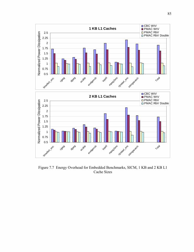
85
1 KB L1 Caches
0.5
0.75
1
1.25
1.5
1.75
2
2.25
2.5
blowfis
h_en
ccjp
egdjp
egec
dhb
ecelg
encb
ispell
mpeg2e
nc
rijnda
el_en
c
string
searc
hTota
l
Nor
mal
ized
Pow
er D
issi
patio
n
CBC WtVPMAC WtVPMAC RbVPMAC RbV Double
2 KB L1 Caches
0.5
0.75
1
1.25
1.5
1.75
2
2.25
2.5
blowfis
h_en
ccjp
egdjp
egec
dhb
ecelg
encb
ispell
mpeg2e
nc
rijnda
el_en
c
string
searc
hTota
l
Nor
mal
ized
Pow
er D
issi
patio
n
CBC WtVPMAC WtVPMAC RbVPMAC RbV Double
Figure 7.7 Energy Overhead for Embedded Benchmarks, SICM, 1 KB and 2 KB L1 Cache Sizes

86
4 KB L1 Caches
0.5
0.75
1
1.25
1.5
1.75
2
2.25
2.5
blowfis
h_en
ccjp
egdjp
egec
dhb
ecelg
encb
ispell
mpeg2e
nc
rijnda
el_en
c
string
searc
hTota
l
Nor
mal
ized
Pow
er D
issi
patio
n
CBC WtVPMAC WtVPMAC RbVPMAC RbV Double
8 KB L1 Caches
0.5
0.75
1
1.25
1.5
1.75
2
2.25
2.5
blowfis
h_en
ccjp
egdjp
egec
dhb
ecelg
encb
ispell
mpeg2e
nc
rijnda
el_en
c
string
searc
hTota
l
Nor
mal
ized
Pow
er D
issi
patio
n
CBC WtVPMAC WtVPMAC RbVPMAC RbV Double
Figure 7.8 Energy Overhead for Embedded Benchmarks, SICM, 4 KB and 8 KB L1 Cache Sizes

87
Table 7.4 Energy Overhead for Embedded Benchmarks, SICM, 1 KB and 2 KB L1 Cache Sizes
Energy Overhead [%]
Benchmark CBC WtV
PMAC WtV
PMAC RBV
PMAC RBV
Double
1 KB 2 KB 1 KB 2 KB 1 KB 2 KB 1 KB 2 KB blowfish_enc 72.3 13.7 49.9 9.44 3.17 0.60 -12.2 -1.69 cjpeg 25.3 5.22 17.5 3.59 1.17 0.24 -1.45 0.36 djpeg 31.9 18.0 21.8 12.3 1.26 0.65 -2.43 -1.39 ecdhb 77.4 35.6 53.5 24.7 3.60 1.49 -11.8 -5.90 ecelgencb 68.7 18.8 47.5 13.0 3.24 0.78 -3.91 -3.07 ispell 99.6 88.4 68.6 60.8 4.43 4.09 -7.45 0.61 mpeg2enc 8.68 5.05 5.98 3.50 0.40 0.24 -0.56 -0.38 rijndael_enc 116.8 117.5 80.1 80.7 3.72 3.83 -14.0 -16.0 stringsearch 96.3 79.2 66.5 54.9 4.44 3.85 2.02 -1.93 Total 90.9 72.6 62.6 50.0 3.79 3.01 -9.17 -3.63
Table 7.5 Energy Overhead for Embedded Benchmarks, SICM, 4 KB and 8 KB L1 Cache Sizes
Energy Overhead [%]
Benchmark CBC WtV
PMAC WtV
PMAC RBV
PMAC RBV
Double
4 KB 8 KB 4 KB 8 KB 4 KB 8 KB 4 KB 8 KB blowfish_enc 0.17 0.00 0.14 0.00 0.09 0.00 0.06 -0.01 cjpeg 1.13 0.29 0.77 0.19 0.00 0.00 0.06 0.00 djpeg 4.88 0.87 3.30 0.53 0.07 0.00 -0.21 -0.08 ecdhb 14.2 0.78 9.84 0.54 0.65 0.03 -1.94 -0.06 ecelgencb 6.57 0.34 4.55 0.24 0.30 0.01 -0.90 -0.04 ispell 49.6 10.4 34.3 7.21 2.64 0.51 4.37 1.35 mpeg2enc 2.16 1.09 1.50 0.76 0.13 0.09 -0.05 -0.02 rijndael_enc 93.6 24.1 64.3 16.2 3.13 0.00 -8.23 7.61 stringsearch 23.6 10.4 16.3 7.14 1.38 0.31 5.80 1.77 Total 43.1 7.65 29.7 5.23 1.88 0.16 -0.12 1.54

88
before, some benchmarks benefit from the prefetching behavior in the double-sized
protected block implementation, dissipating less power due to shorter runtimes.
The normalized power dissipation values of the SPEC benchmarks running in
SICM mode are plotted in Figure 7.9 and Figure 7.10, and presented numerically in
Table 7.6. Level 1 cache sizes vary between 8 KB, 16 KB, and 32 KB. As with the
embedded benchmarks, the energy overhead closely follows the performance overhead.
The only benchmark showing any appreciable overhead is gcc, and this is reduced to less
than 25% with an I-cache size of 32 KB.
8 KB L1 Caches
0.5
0.75
1
1.25
1.5
1.75
2
2.25
2.5
bzip2 gcc gzip parser Total
Nor
mal
ized
Pow
er D
issi
patio
n
CBC WtVPMAC WtVPMAC RbVPMAC RbV Double
Figure 7.9 Energy Overhead for SPEC Benchmarks, SICM, 8 KB L1 Cache Size

89
16 KB L1 Caches
0.5
0.75
1
1.25
1.5
1.75
2
2.25
2.5
bzip2 gcc gzip parser Total
Nor
mal
ized
Pow
er D
issi
patio
n
CBC WtVPMAC WtVPMAC RbVPMAC RbV Double
32 KB L1 Caches
0.5
0.75
1
1.25
1.5
1.75
2
2.25
2.5
bzip2 gcc gzip parser Total
Nor
mal
ized
Pow
er D
issi
patio
n
CBC WtVPMAC WtVPMAC RbVPMAC RbV Double
Figure 7.10 Energy Overhead for SPEC Benchmarks, SICM, 16 KB and 32 KB Cache Sizes
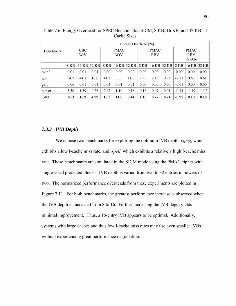
90
Table 7.6 Energy Overhead for SPEC Benchmarks, SICM, 8 KB, 16 KB, and 32 KB L1 Cache Sizes
Energy Overhead [%]
Benchmark CBC WtV
PMAC WtV
PMAC RBV
PMAC RBV
Double 8 KB 16 KB 32 KB 8 KB 16 KB 32 KB 8 KB 16 KB 32 KB 8 KB 16 KB 32 KBbzip2 0.01 0.01 0.01 0.00 0.00 0.00 0.00 0.00 0.00 0.00 0.00 0.00 gcc 64.2 44.1 16.0 44.3 30.5 11.0 2.90 2.13 0.76 -2.21 0.63 0.61 gzip 0.06 0.01 0.01 0.04 0.01 0.01 0.00 0.00 0.00 -0.01 0.00 0.00 parser 3.50 1.59 0.26 2.42 1.10 0.18 0.16 0.07 0.01 -0.44 -0.19 -0.02
Total 26.3 15.9 4.99 18.2 11.0 3.44 1.19 0.77 0.24 -0.97 0.18 0.18
7.3.3 IVB Depth
We choose two benchmarks for exploring the optimum IVB depth: cjpeg, which
exhibits a low I-cache miss rate, and ispell, which exhibits a relatively high I-cache miss
rate. These benchmarks are simulated in the SICM mode using the PMAC cipher with
single-sized protected blocks. IVB depth is varied from two to 32 entries in powers of
two. The normalized performance overheads from these experiments are plotted in
Figure 7.11. For both benchmarks, the greatest performance increase is observed when
the IVB depth is increased from 8 to 16. Further increasing the IVB depth yields
minimal improvement. Thus, a 16-entry IVB appears to be optimal. Additionally,
systems with large caches and thus low I-cache miss rates may use even smaller IVBs
without experiencing great performance degradation.

91
cjpeg
0.99
1
1.01
1.02
1.03
1.04
1.05
2 4 8 16 32
IVB Depth
Nor
mal
ized
Exe
cutio
n Ti
me
1 KB Caches2 KB Caches4 KB Caches8 KB Caches
ispell
0.981
1.021.041.061.081.1
1.121.141.161.181.2
2 4 8 16 32
IVB Depth
Nor
mal
ized
Exe
cutio
n Ti
me
1 KB Caches2 KB Caches4 KB Caches8 KB Caches
Figure 7.11 IVB Depth Evaluation

92
7.4 Data Protection Architecture (DICM) Overhead
Performance overhead is also evaluated for the data protection architecture. The
simulator used to evaluate the overhead of the DICM mode is an extended version of the
simulator for SICM mode. We use the most efficient single-sized protected block SICM
implementation, PMAC RbV, which has been shown above to introduce negligible
performance overhead. We again use the normalized execution time metric to evaluate
the DICM architecture.
The normalized execution times for embedded benchmarks running in both the
SICM and DICM modes are shown in Figure 7.12 through Figure 7.15, and presented
numerically in Table 7.7. Results are shown for 1 KB, 2 KB, 4 KB, and 8 KB cache
sizes. Within each cache size, the sequence number cache size is varied between 25% of
the data cache size (thus 256 B, 512 B, 1 KB, and 2 KB) and 50% of the data cache (thus
512 B, 1 KB, 2 KB, and 4 KB). All sequence number caches are 4-way set associative.
The figures break down the overhead between the contributions from the SICM and
DICM modes, while the table includes only the overhead from the DICM mode. These
results show that the DICM architecture incurs significant overhead for small D-cache
sizes. This overhead greatly decreases as D-cache size increases; all benchmarks exhibit
less than 25% performance overhead with an 8 KB D-cache. They also indicate that
larger sequence number caches significantly reduce the performance overhead of most
benchmarks on systems with small D-caches, but offer little improvement for systems
with large D-caches. Thus the choice of sequence number cache size in an actual
hardware implementation should be driven by the expected workload of the system and

93
1 KB L1 Caches, 256 B Seqnum Cache
1.03 1.01 1.01 1.03 1.03 1.04 1.00 1.04 1.04 1.04
0.70 1.63 2.04 0.15 0.07 0.74 1.16 1.53 1.22 0.85
0.5
1
1.5
2
2.5
3
blowfis
h_en
ccjp
egdjp
egec
dhb
ecelg
encb
ispell
mpeg2e
nc
rijnda
el_en
c
string
searc
hTota
l
Nor
mal
ized
Exe
cutio
n Ti
me
DICMSICM
1 KB L1 Caches, 512 B Seqnum Cache
1.03 1.01 1.01 1.03 1.03 1.04 1.00 1.04 1.04 1.04
0.13 1.00 0.85 0.08 0.03 0.52 0.53 0.64 0.60 0.44
0.5
1
1.5
2
2.5
3
blowfis
h_en
ccjp
egdjp
egec
dhb
ecelg
encb
ispell
mpeg2e
nc
rijnda
el_en
c
string
searc
hTota
l
Nor
mal
ized
Exe
cutio
n Ti
me
DICMSICM
Figure 7.12 Performance Overhead for Embedded Benchmarks, SICM/DICM, 1 KB L1 Cache Size

94
2 KB L1 Caches, 512 B Seqnum Cache
1.01 1.00 1.01 1.01 1.01 1.04 1.00 1.04 1.04 1.03
0.33 0.81 0.76 0.03 0.01 0.44 0.35 0.60 0.43 0.43
0.5
1
1.5
2
2.5
3
blowfis
h_en
ccjp
egdjp
egec
dhb
ecelg
encb
ispell
mpeg2e
nc
rijnda
el_en
c
string
searc
hTota
l
Nor
mal
ized
Exe
cutio
n Ti
me
DICMSICM
2 KB L1 Caches, 1 KB Seqnum Cache
1.01 1.00 1.01 1.01 1.01 1.04 1.00 1.04 1.04 1.03
0.20 0.24 0.46 0.01 0.01 0.35 0.19 0.35 0.26 0.29
0.5
1
1.5
2
2.5
3
blowfis
h_en
ccjp
egdjp
egec
dhb
ecelg
encb
ispell
mpeg2e
nc
rijnda
el_en
c
string
searc
hTota
l
Nor
mal
ized
Exe
cutio
n Ti
me
DICMSICM
Figure 7.13 Performance Overhead for Embedded Benchmarks, SICM/DICM, 2 KB L1 Cache Size

95
4 KB L1 Caches, 1 KB Seqnum Cache
1.00 1.00 1.00 1.01 1.00 1.03 1.00 1.03 1.01 1.02
0.10 0.18 0.40 0.00 0.00 0.05 0.08 0.42 0.11 0.15
0.5
1
1.5
2
2.5
3
blowfis
h_en
ccjp
egdjp
egec
dhb
ecelg
encb
ispell
mpeg2e
nc
rijnda
el_en
c
string
searc
hTota
l
Nor
mal
ized
Exe
cutio
n Ti
me
DICMSICM
4 KB L1 Caches, 2 KB Seqnum Cache
1.00 1.00 1.00 1.01 1.00 1.03 1.00 1.03 1.01 1.02
0.09 0.15 0.29 0.00 0.00 0.04 0.06 0.30 0.05 0.11
0.5
1
1.5
2
2.5
3
blowfis
h_en
ccjp
egdjp
egec
dhb
ecelg
encb
ispell
mpeg2e
nc
rijnda
el_en
c
string
searc
hTota
l
Nor
mal
ized
Exe
cutio
n Ti
me
DICMSICM
Figure 7.14 Performance Overhead for Embedded Benchmarks, SICM/DICM, 4 KB L1 Cache Size
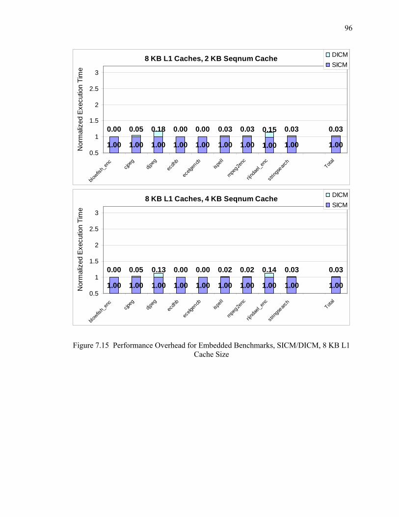
96
8 KB L1 Caches, 2 KB Seqnum Cache
1.00 1.00 1.00 1.00 1.00 1.00 1.00 1.00 1.00 1.00
0.00 0.05 0.18 0.00 0.00 0.03 0.03 0.15 0.03 0.03
0.5
1
1.5
2
2.5
3
blowfis
h_en
ccjp
egdjp
egec
dhb
ecelg
encb
ispell
mpeg2e
nc
rijnda
el_en
c
string
searc
hTota
l
Nor
mal
ized
Exe
cutio
n Ti
me
DICMSICM
8 KB L1 Caches, 4 KB Seqnum Cache
1.00 1.00 1.00 1.00 1.00 1.00 1.00 1.00 1.00 1.00
0.00 0.05 0.13 0.00 0.00 0.02 0.02 0.14 0.03 0.03
0.5
1
1.5
2
2.5
3
blowfis
h_en
ccjp
egdjp
egec
dhb
ecelg
encb
ispell
mpeg2e
nc
rijnda
el_en
c
string
searc
hTota
l
Nor
mal
ized
Exe
cutio
n Ti
me
DICMSICM
Figure 7.15 Performance Overhead for Embedded Benchmarks, SICM/DICM, 8 KB L1 Cache Size
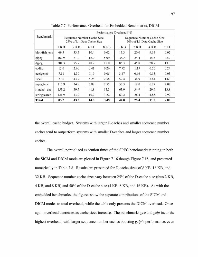
97
Table 7.7 Performance Overhead for Embedded Benchmarks, DICM
Performance Overhead [%] Benchmark Sequence Number Cache Size
25% of L1 Data Cache Size Sequence Number Cache Size 50% of L1 Data Cache Size
1 KB 2 KB 4 KB 8 KB 1 KB 2 KB 4 KB 8 KB blowfish_enc 69.5 33.5 10.4 0.02 13.3 20.0 9.14 0.02 cjpeg 162.9 81.0 18.0 5.09 100.4 24.4 15.3 4.52 djpeg 204.3 75.7 40.2 18.0 85.3 45.8 28.7 13.0 ecdhb 15.0 2.60 0.41 0.26 7.92 1.15 0.26 0.24 ecelgencb 7.11 1.30 0.19 0.05 3.47 0.66 0.15 0.03 ispell 73.6 43.9 5.28 2.58 52.4 34.9 3.61 1.60 mpeg2enc 115.9 34.9 7.88 2.55 53.3 19.0 6.27 2.02 rijndael_enc 153.2 59.7 41.8 15.3 63.9 34.9 29.9 13.8 stringsearch 121.9 43.2 10.7 3.22 60.2 26.4 4.85 2.92
Total 85.2 43.3 14.9 3.49 44.0 29.4 11.0 2.80
the overall cache budget. Systems with larger D-caches and smaller sequence number
caches tend to outperform systems with smaller D-caches and larger sequence number
caches.
The overall normalized execution times of the SPEC benchmarks running in both
the SICM and DICM mode are plotted in Figure 7.16 though Figure 7.18, and presented
numerically in Table 7.8. Results are presented for D-cache sizes of 8 KB, 16 KB, and
32 KB. Sequence number cache sizes vary between 25% of the D-cache size (thus 2 KB,
4 KB, and 8 KB) and 50% of the D-cache size (4 KB, 8 KB, and 16 KB). As with the
embedded benchmarks, the figures show the separate contributions of the SICM and
DICM modes to total overhead, while the table only presents the DICM overhead. Once
again overhead decreases as cache sizes increase. The benchmarks gcc and gzip incur the
highest overhead, with larger sequence number caches boosting gzip’s performance, even

98
8 KB L1 Caches, 2 KB Seqnum Cache
1.00 1.03 1.00 1.00 1.01
0.20 0.34 1.12 0.03 0.43
0.5
0.75
1
1.25
1.5
1.75
2
2.25
2.5
bzip2 gcc gzip parser Total
Nor
mal
ized
Exe
cutio
n Ti
me
DICMSICM
8 KB L1 Caches, 4 KB Seqnum Cache
1.00 1.03 1.00 1.00 1.01
0.16 0.29 0.93 0.02 0.36
0.5
0.75
1
1.25
1.5
1.75
2
2.25
2.5
bzip2 gcc gzip parser Total
Nor
mal
ized
Exe
cutio
n Ti
me
DICMSICM
Figure 7.16 Performance Overhead for SPEC Benchmarks, SICM/DICM, 8 KB L1
Cache Size

99
16 KB L1 Caches, 4 KB Seqnum Cache
1.00 1.02 1.00 1.00 1.01
0.14 0.28 0.87 0.01 0.34
0.5
0.75
1
1.25
1.5
1.75
2
2.25
2.5
bzip2 gcc gzip parser Total
Nor
mal
ized
Exe
cutio
n Ti
me
DICMSICM
16 KB L1 Caches, 8 KB Seqnum Cache
1.00 1.02 1.00 1.00 1.01
0.13 0.25 0.60 0.01 0.26
0.5
0.75
1
1.25
1.5
1.75
2
2.25
2.5
bzip2 gcc gzip parser Total
Nor
mal
ized
Exe
cutio
n Ti
me
DICMSICM
Figure 7.17 Performance Overhead for SPEC Benchmarks, SICM/DICM, 16 KB L1 Cache Size
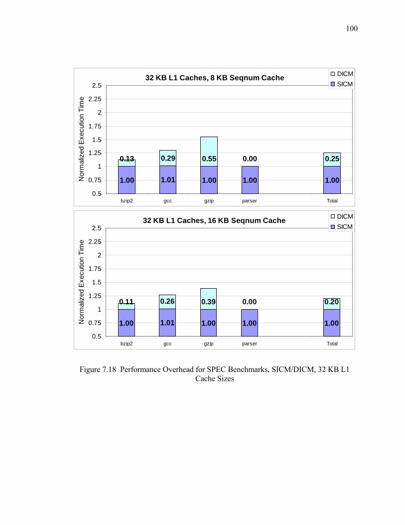
100
32 KB L1 Caches, 8 KB Seqnum Cache
1.00 1.01 1.00 1.00 1.00
0.13 0.29 0.55 0.00 0.25
0.5
0.75
1
1.25
1.5
1.75
2
2.25
2.5
bzip2 gcc gzip parser Total
Nor
mal
ized
Exe
cutio
n Ti
me
DICMSICM
32 KB L1 Caches, 16 KB Seqnum Cache
1.00 1.01 1.00 1.00 1.00
0.11 0.26 0.39 0.00 0.20
0.5
0.75
1
1.25
1.5
1.75
2
2.25
2.5
bzip2 gcc gzip parser Total
Nor
mal
ized
Exe
cutio
n Ti
me
DICMSICM
Figure 7.18 Performance Overhead for SPEC Benchmarks, SICM/DICM, 32 KB L1 Cache Sizes
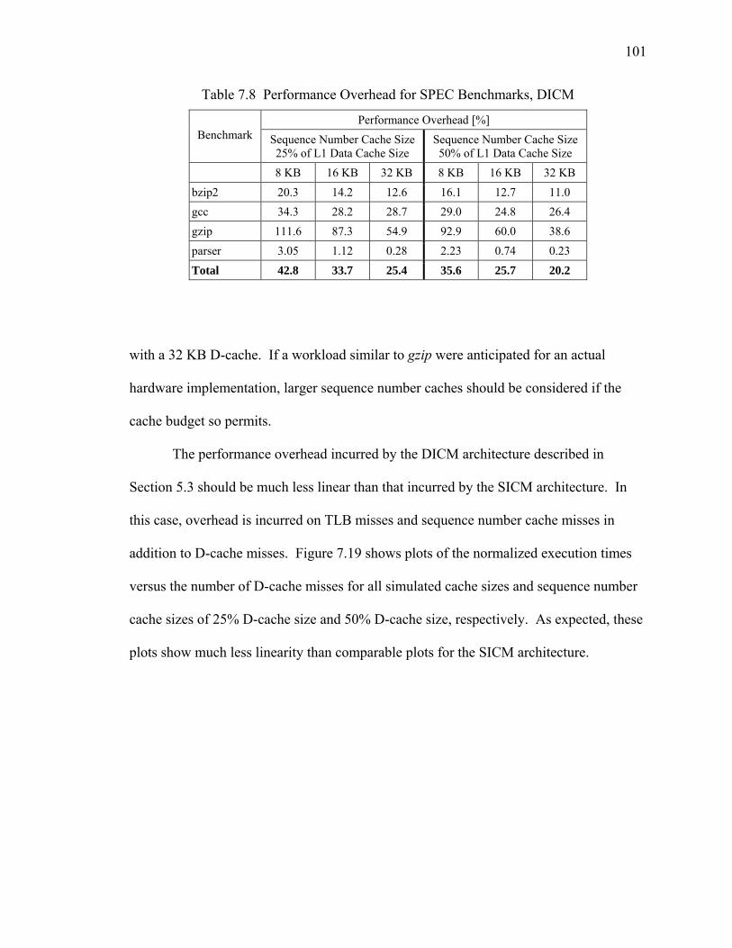
101
Table 7.8 Performance Overhead for SPEC Benchmarks, DICM
Performance Overhead [%] Benchmark Sequence Number Cache Size
25% of L1 Data Cache Size Sequence Number Cache Size 50% of L1 Data Cache Size
8 KB 16 KB 32 KB 8 KB 16 KB 32 KB bzip2 20.3 14.2 12.6 16.1 12.7 11.0 gcc 34.3 28.2 28.7 29.0 24.8 26.4 gzip 111.6 87.3 54.9 92.9 60.0 38.6 parser 3.05 1.12 0.28 2.23 0.74 0.23 Total 42.8 33.7 25.4 35.6 25.7 20.2
with a 32 KB D-cache. If a workload similar to gzip were anticipated for an actual
hardware implementation, larger sequence number caches should be considered if the
cache budget so permits.
The performance overhead incurred by the DICM architecture described in
Section 5.3 should be much less linear than that incurred by the SICM architecture. In
this case, overhead is incurred on TLB misses and sequence number cache misses in
addition to D-cache misses. Figure 7.19 shows plots of the normalized execution times
versus the number of D-cache misses for all simulated cache sizes and sequence number
cache sizes of 25% D-cache size and 50% D-cache size, respectively. As expected, these
plots show much less linearity than comparable plots for the SICM architecture.

102
25% Seqnum Cache
0.50.75
11.25
1.51.75
22.25
2.52.75
33.25
0 50 100 150 200 250D-Cache Misses per 1,000 Instructions
Nor
mal
ized
Exe
cutio
n Ti
me
50% Seqnum Cache
0.5
0.75
1
1.25
1.5
1.75
2
2.25
2.5
0 50 100 150 200 250D-Cache Misses per 1,000 Instructions
Nor
mal
ized
Exe
cutio
n Ti
me
Figure 7.19 Normalized Execution Time vs. D-Cache Miss Rate, DICM

103
CHAPTER 8
CONCLUSIONS AND FUTURE WORK
This thesis directly addresses the issues of integrity and confidentiality for both
software instructions and data in embedded systems. The issue of availability is
addressed indirectly, in so far as violation of integrity and/or confidentiality may lead to a
loss of availability. Two architectures are proposed for ensuring integrity and
confidentiality, one protecting instructions and the other protecting data. These
architectures may be implemented independently or combined as needed. Both
architectures use encryption to ensure confidentiality and verification of signatures
embedded in instruction and data pages to ensure integrity. The data protection
architecture addresses the additional needs of dynamic data by including sequence
numbers in both the encryption and signature processes.
Analysis of these proposed architectures reveals the following findings:
• Both architectures can be implemented with relatively low complexity. The most
complex component, the cryptographic pipeline, may be shared between the two
architectures.
• The instruction protection architecture using the PMAC cipher with an IVB
introduces very low performance and energy overhead.

104
• The data protection architecture introduces significant performance overhead for
systems with extremely small caches, but that overhead dramatically decreases for
larger cache sizes.
• Both architectures incur memory overheads of up to 50%. The memory overhead
caused by the instruction protection architecture may be reduced to 25% with no
increase in performance overhead.
The large volume of embedded computer systems and the resourceful nature of
attackers lead to many opportunities for future research in the field of secure computing.
The work presented in this thesis may be extended and improved in the future. Areas for
future research on these architectures include the following:
• Further analyze the cryptographic strength of the proposed architectures and
increasing that strength as appropriate.
• Investigate any possible vulnerabilities to side-channel attacks.
• Extend the power dissipation model to include the data protection architecture.
• Modify the data protection architecture to allow one signature to protect multiple
data blocks, thus reducing memory overhead.
• Tweak the data protection architecture to make more efficient use of memory and
the cryptographic pipeline when a sequence number cache miss occurs during a
data cache miss.

105
REFERENCES
[1] US-CERT, "US-CERT Cyber Security Bulletin 2005 Summary," <http://www.us-
cert.gov/cas/bulletins/SB2005.html> (Available August 2007).
[2] BSA, "2007 Global Piracy Study," <http://w3.bsa.org/globalstudy/> (Available August 2007).
[3] J. Turley, "Embedded Processors by the Numbers," <http://www.embedded.com/1999/9905/9905turley.htm > (Available August 2007).
[4] M. Milenković, "Architectures for Run-Time Verification of Code Integrity," Ph.D. Thesis, Electrical and Computer Engineering Department, University of Alabama in Huntsville, 2005.
[5] D. Ahmad, "The Rising Threat of Vulnerabilities Due to Integer Errors," IEEE Security & Privacy, vol. 1, July-August 2003, pp. 77-82.
[6] Anonymous, "Once Upon a Free()," <http://www.phrack.org/issues.html?issue=57&id=9#article> (Available August 2007).
[7] N. R. Potlapally, A. Raghunathan, S. Ravi, N. K. Jha, and R. B. Lee, "Satisfiability-Based Framework for Enabling Side-Channel Attacks on Cryptographic Software," in Advances in Cryptology: Proceedings of EUROCRYPT '97, Konstanz, Germany, 1997, pp. 37-51.
[8] P. Kocher, "Cryptanalysis of Diffie-Hellman, RSA, DSS, and Other Systems Using Timing Attacks," 1995.
[9] P. Kocher, J. Jaffe, and B. Jun, "Differential Power Analysis," in Advances in Cryptology: Proceedings of CRYPTO '99, Santa Barbara, CA, USA, 1999, pp. 388-397.
[10] D. Boneh, R. A. DeMillo, and R. J. Lipton, "On the Importance of Checking Cryptographic Protocols for Faults," Cryptology, vol. 14, February 2001, pp. 101-119.
[11] O. Aciiçmez, Ç. K. Koç, and J.-P. Seifert, "On the Power of Simple Branch Prediction Analysis," in Proceedings of the 2nd ACM Symposium on Information, Computer and Communications Security, Singapore, 2007, pp. 312-320.

106
[12] M. Milenković, A. Milenković, and J. Kulick, "Microbenchmarks for Determining Branch Predictor Organization," Software Practice & Experience, vol. 34, April 2004, pp. 465-487.
[13] J. Xu, Z. Kalbarczyk, S. Patel, and R. K. Iyer, "Architecture Support for Defending against Buffer Overflow Attacks," in Workshop on Evaluating and Architecting System Dependability (EASY), San Jose, CA, USA, 2002, pp. 50-56.
[14] H. Ozdoganoglu, C. E. Brodley, T. N. Vijaykumar, B. A. Kuperman, and A. Jalote, "Smashguard: A Hardware Solution to Prevent Security Attacks on the Function Return Address," Purdue University, TR-ECE 03-13, November 2003.
[15] N. Tuck, B. Calder, and G. Varghese, "Hardware and Binary Modification Support for Code Pointer Protection from Buffer Overflow," in 37th Annual ACM/IEEE International Symposium on Microarchitecture (MICRO), Portland, OR, USA, 2004, pp. 209-220.
[16] G. E. Suh, J. W. Lee, and S. Devadas, "Secure Program Execution Via Dynamic Information Flow Tracking," in 11th Architectural Support for Programming Languages and Operating Systems (ASPLOS), Boston, MA, USA, 2004, pp. 85-96.
[17] J. R. Crandall and F. T. Chong, "Minos: Control Data Attack Prevention Orthogonal to Memory Model," in 37th Annual IEEE/ACM International Symposium on Microarchitecture (MICRO), Portland, OR, USA, 2004, pp. 221-232.
[18] D. Lie, C. Thekkath, M. Mitchell, P. Lincolny, D. Boneh, J. Mitchell, and M. Horowitz, "Architectural Support for Copy and Tamper Resistant Software," in 9th International Conference on Architectural Support for Programming Languages and Operating Systems, Cambridge, MA, USA, 2000, pp. 168-177.
[19] D. Lie, J. Mitchell, C. A. Thekkath, and M. Horowitz, "Specifying and Verifying Hardware for Tamper-Resistant Software," in IEEE Conference on Security and Privacy, Berkeley, CA, USA, 2003, pp. 166-177.
[20] J. Yang, L. Gao, and Y. Zhang, "Improving Memory Encryption Performance in Secure Processors," IEEE Transactions on Computers, vol. 54, May 2005, pp. 630-640.
[21] B. Gassend, G. E. Suh, D. Clarke, M. v. Dijk, and S. Devadas, "Caches and Hash Trees for Efficient Memory Integrity Verification," in Proceedings of the 9th International Symposium on High-Performance Computer Architecture, Anaheim, CA, USA, 2003, pp. 295-306.
[22] C. Lu, T. Zhang, W. Shi, and H.-H. S. Lee, "M-TREE: A High Efficiency Security Architecture for Protecting Integrity and Privacy of Software," Journal of Parallel and Distributed Computing, vol. 66, September 2006, pp. 1116-1128.

107
[23] G. E. Suh, D. Clarke, B. Gassend, M. v. Dijk, and S. Devadas, "Efficient Memory Integrity Verification and Encryption for Secure Processors," in Proceedings of the 36th International Symposium on Microarchitecture, San Diego, CA, USA, 2003, pp. 339-350.
[24] G. E. Suh, W. O. D. Charles, S. Ishan, and D. Srinivas, "Design and Implementation of the AEGIS Single-Chip Secure Processor Using Physical Random Functions," in Proceedings of the 32nd Annual International Symposium on Computer Architecture, Madison, WI, USA, 2005, pp. 25-36.
[25] M. Milenković, A. Milenković, and E. Jovanov, "A Framework for Trusted Instruction Execution Via Basic Block Signature Verification," in 42nd Annual ACM Southeast Conference, Huntsville, AL, USA, 2004, pp. 191-196.
[26] M. Milenković, A. Milenković, and E. Jovanov, "Using Instruction Block Signatures to Counter Code Injection Attacks," in Workshop on Architectural Support for Security and Anti-Virus (WASSA), Boston, MA, USA, 2004, pp. 104-113.
[27] M. Milenković, A. Milenković, and E. Jovanov, "Hardware Support for Code Integrity in Embedded Processors," in Proceedings of the 2005 International Conference on Compilers, Architectures and Synthesis for Embedded Systems, San Francisco, CA, USA, 2005, pp. 55-65.
[28] A. Milenković, M. Milenković, and E. Jovanov, "An Efficient Runtime Instruction Block Verification for Secure Embedded Systems," Journal of Embedded Computing, vol. 4, January 2006, pp. 57-76.
[29] M. Drinic and D. Kirovski, "A Hardware-Software Platform for Intrusion Prevention," in 37th Annual ACM/IEEE International Symposium on Microarchitecture (MICRO), Portland, OR, USA, 2004, pp. 233-242.
[30] Intel, "Execute Disable Bit and Enterprise Security," <http://www.intel.com/business/bss/infrastructure/security/xdbit.htm> (Available August 2007).
[31] A. Zeichick, "Security Ahoy! Flying the NX Flag on Windows and AMD64 to Stop Attacks," <http://developer.amd.com/articlex.jsp?id=143> (Available August 2007).
[32] IBM, "IBM Extends Enhanced Data Security to Consumer Electronics Products," <http://www-03.ibm.com/press/us/en/pressrelease/19527.wss> (Available August 2007).
[33] T. Alves and D. Felton, "Trustzone: Integrated Hardware and Software Security," I.Q. Publication, vol. 3, November 2004, pp. 18-24.

108
[34] MAXIM, "Increasing System Security by Using the DS5250 as a Secure Coprocessor," <http://www.maxim-ic.com/appnotes.cfm/appnote_number/3294> (Available August 2007).
[35] D. Kirovski, M. Drinic, and M. Potkonjak, "Enabling Trusted Software Integrity," in 10th International Conference on Architectural Support for Programming Languages and Operating Systems (ASPLOS-X), San Jose, CA, USA, 2002, pp. 108-120.
[36] J. H. An, Y. Dodis, and T. Rabin, "On the Security of Joint Signature and Encryption," in Advances in Cryptology: Proceedings of EUROCRYPT 2002 Amsterdam, Netherlands, 2002, pp. 83-107.
[37] M. Bellare and C. Namprempre, "Authenticated Encryption: Relations among Notions and Analysis of the Generic Composition Paradigm," in Advances in Cryptology: Proceedings of EUROCRYPT 2000, Bruges, Belgium, 2000, pp. 531-545.
[38] N. Ferguson and B. Schneier, Practical Cryptography: John Wiley & Sons, 2003.
[39] Y.-H. Wang, H.-G. Zhang, Z.-D. Shen, and K.-S. Li, "Thermal Noise Random Number Generator Based on SHA-2 (512)," in Proceedings of 2005 International Conference on Machine Learning and Cybernetics, Guangzhou, China, 2005, pp. 3970-3974.
[40] J. Black and P. Rogaway, "A Block-Cipher Mode of Operation for Parallelizable Message Authentication," in Advances in Cryptology: Proceedings of EUROCRYPT 2002, Amsterdam, Netherlands, 2002, pp. 384-397.
[41] W. Shi and H.-H. S. Lee, "Accelerating Memory Decryption with Frequent Value Prediction," in ACM International Conference on Computing Frontiers, Ischia, Italy, 2007, pp. 35-46.
[42] TIS, "Executable and Linking Format (Elf) Specification," <http://x86.ddj.com/ftp/manuals/tools/elf.pdf> (Available January 2005).
[43] M. R. Guthaus, J. S. Ringenberg, D. Ernst, T. M. Austin, T. Mudge, and R. B. Brown, "MiBench: A Free, Commercially Representative Embedded Benchmark Suite," in IEEE 4th Annual Workshop on Workload Characterization, Austin, TX, USA, 2001, pp. 3-14.
[44] C. Lee, M. Potkonjak, and W. H. Mangione-Smith, "MediaBench: A Tool for Evaluating and Synthesizing Multimedia and Communications Systems," IEEE Micro, vol. 30, December 1997, pp. 330-335.
[45] I. Branovic, R. Giorgi, and E. Martinelli, "A Workload Characterization of Elliptic Curve Cryptography Methods in Embedded Environments," ACM SIGARCH Computer Architecture News, vol. 32, June 2004, pp. 27-34.

109
[46] SPEC, "SPEC 2000 CPU Benchmark Suite," <http://www.spec.org> (Available August 2007).
[47] T. Sherwood, E. Perelman, G. Hamerly, and B. Calder, "Automatically Characterizing Large Scale Program Behavior," in Proceedings of the 10th International Conference on Architectural Support for Programming Languages and Operating Systems, San Jose, CA, USA, 2002, pp. 45-57.
[48] N. Kim, T. Kgil, V. Bertacco, T. Austin, and T. Mudge, "Microarchitectural Power Modeling Techniques for Deep Sub-Micron Microprocessors," in International Symposium on Low Power Electronics and Design (ISLPED), Newport Beach, CA, USA, 2004, pp. 212-217.
[49] T. Austin, E. Larson, and D. Ernst, "SimpleScalar: An Infrastructure for Computer System Modeling," IEEE Computer, vol. 35, February 2002, pp. 59-67.
[50] "Cadence Aes Cores," <http://www.cadence.com/datasheets/AES_DataSheet.pdf> (Available August 2007).