low-cost programmable pulse generator for particle telescope calibration
TRANSCRIPT
qWork supported by the ComisioH n Internacional de Cienciay TecnologmHa (CICYT) of Spain, grant ESP95-0612, and by theDireccioH n General de InvestigacioH n CientmH "ca y TeH cnica(DGICYT) of Spain, grant UR1995-0168-01.
*Corresponding author. Tel.: #34-91-885-6602; fax: #34-91-885-6641.
E-mail address: [email protected] (S. SaH nchez)
Nuclear Instruments and Methods in Physics Research A 436 (1999) 386}393
Low-cost programmable pulse generator for particle telescopecalibrationq
S. SaH nchez!,*, M. GonzaH lez!, M. Seisdedos!, D. Meziat!, M. Carbajo!, J. Medina",E. Bronchalo", L. del Peral", J. RodrmHguez-Pacheco"
! Computing Engineering Department, Universidad de Alcala& , 28871 Alcala& de Henares, Madrid, Spain" Physics Department, Universidad de Alcala& , 28871 Alcala& de Henares, Madrid, Spain
Received 10 March 1999; accepted 14 May 1999
Abstract
In this paper we present a new calibration system for particle telescopes including multipulse generator and digitalcontroller. The calibration system generates synchronized pulses of variable height for every detector channel on thetelescope. The control system is based on a commercial microcontroller linked to a personal computer through anRS-232 bidirectional line. The aim of the device is to perform laboratory calibration of multi-detector telescopes prior tocalibration at accelerator. This task includes evaluation of linearity and resolution of each detector channel, as well ascoincidence logic. The heights of the pulses sent to the detectors are obtained by Monte Carlo simulation of telescoperesponse to a particle #ux of any desired geometry and composition. ( 1999 Elsevier Science B.V. All rights reserved.
PACS: 84.30.Ng; 84.30.Sk
Keywords: Pulse generators; Particle telescopes calibration
1. Introduction
To assure a correct interpretation of data ob-tained with scienti"c instruments onboard satel-lites, as well as to compare these data with those ofsimilar instruments, a thorough pre-#ight cali-bration is required. For solar and cosmic ray particle
telescopes, this calibration is usually carried out intwo steps: "rst, a calibration of each individualdetector using radioactive sources and standardnuclear instrumentation (NIM or CAMAC mod-ules), followed by a "nal test of the whole telescopeperformed in a particle accelerator site. The successof calibration on accelerator requires that, prior tothe experience, all detectors and electronics param-eters (polarization voltages, ampli"er gains andshaping times, thresholds, etc.) have nearly de"ni-tive values. Here we propose a cheap and simplepre-calibration procedure based on a new systemthat we have called Programmable Pulse Ge-nerator (PPG). The PPG developed in our labora-tory has been designed for a speci"c instrument, a
0168-9002/99/$ - see front matter ( 1999 Elsevier Science B.V. All rights reserved.PII: S 0 1 6 8 - 9 0 0 2 ( 9 9 ) 0 0 5 5 7 - 4
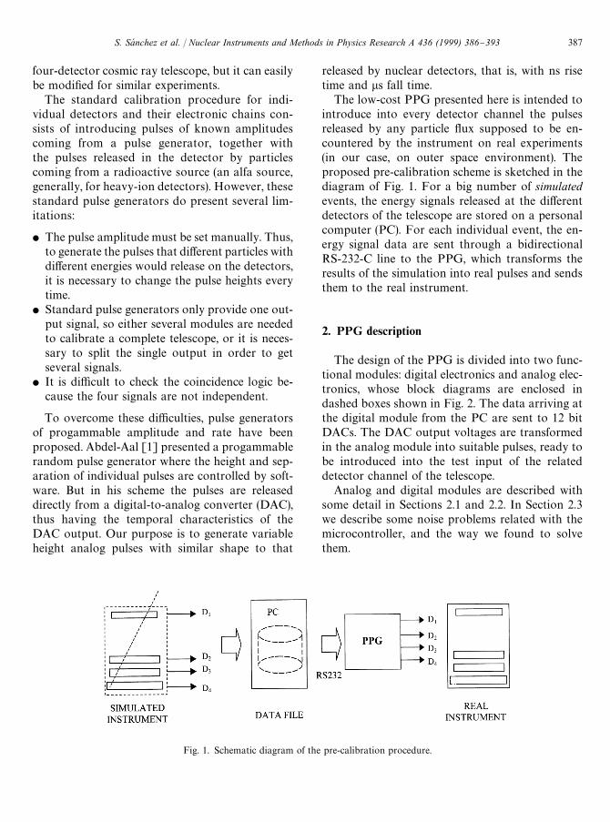
Fig. 1. Schematic diagram of the pre-calibration procedure.
four-detector cosmic ray telescope, but it can easilybe modi"ed for similar experiments.
The standard calibration procedure for indi-vidual detectors and their electronic chains con-sists of introducing pulses of known amplitudescoming from a pulse generator, together withthe pulses released in the detector by particlescoming from a radioactive source (an alfa source,generally, for heavy-ion detectors). However, thesestandard pulse generators do present several lim-itations:
f The pulse amplitude must be set manually. Thus,to generate the pulses that di!erent particles withdi!erent energies would release on the detectors,it is necessary to change the pulse heights everytime.
f Standard pulse generators only provide one out-put signal, so either several modules are neededto calibrate a complete telescope, or it is neces-sary to split the single output in order to getseveral signals.
f It is di$cult to check the coincidence logic be-cause the four signals are not independent.
To overcome these di$culties, pulse generatorsof progammable amplitude and rate have beenproposed. Abdel-Aal [1] presented a progammablerandom pulse generator where the height and sep-aration of individual pulses are controlled by soft-ware. But in his scheme the pulses are releaseddirectly from a digital-to-analog converter (DAC),thus having the temporal characteristics of theDAC output. Our purpose is to generate variableheight analog pulses with similar shape to that
released by nuclear detectors, that is, with ns risetime and ls fall time.
The low-cost PPG presented here is intended tointroduce into every detector channel the pulsesreleased by any particle #ux supposed to be en-countered by the instrument on real experiments(in our case, on outer space environment). Theproposed pre-calibration scheme is sketched in thediagram of Fig. 1. For a big number of simulatedevents, the energy signals released at the di!erentdetectors of the telescope are stored on a personalcomputer (PC). For each individual event, the en-ergy signal data are sent through a bidirectionalRS-232-C line to the PPG, which transforms theresults of the simulation into real pulses and sendsthem to the real instrument.
2. PPG description
The design of the PPG is divided into two func-tional modules: digital electronics and analog elec-tronics, whose block diagrams are enclosed indashed boxes shown in Fig. 2. The data arriving atthe digital module from the PC are sent to 12 bitDACs. The DAC output voltages are transformedin the analog module into suitable pulses, ready tobe introduced into the test input of the relateddetector channel of the telescope.
Analog and digital modules are described withsome detail in Sections 2.1 and 2.2. In Section 2.3we describe some noise problems related with themicrocontroller, and the way we found to solvethem.
S. Sa& nchez et al. / Nuclear Instruments and Methods in Physics Research A 436 (1999) 386}393 387
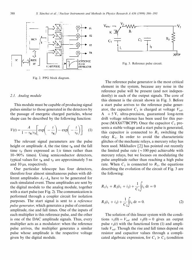
Fig. 2. PPG block diagram.
Fig. 3. Reference pulse circuit.
2.1. Analog module
This module must be capable of producing signalpulses similar to those generated in the detectors bythe passage of energetic charged particles, whoseshape can be described by the following function:
<(t)"A
1!qR/q
FCexpA!
t
qRB!expA!
t
qFBD. (1)
The relevant signal parameters are the pulseheight or amplitude A, the rise time q
Rand the fall
time qF
(here expressed as 1/e times rather than10}90% times). Using semiconductor detectors,typical values for q
Rand q
Fare approximately 5 ns
and 10 ls, respectively.Our particular telescope has four detectors,
therefore four almost simultaneous pulses with dif-ferent amplitudes A
1}A
4have to be generated for
each simulated event. These amplitudes are sent bythe digital module to the analog module, togetherwith a start pulse (see Fig. 2). The communication isperformed through a coupler circuit for isolationpurposes. The start signal is sent to a referencepulse generator, which generates a pulse of constantamplitude, rise and fall times. One of the inputs ofeach multiplier is this reference pulse, and the otheris one of the DAC amplitude signals. Thus, everymultiplier acts as a modulator: when the referencepulse arrives, the multiplier generates a similarpulse whose amplitude is the respective voltagegiven by the digital module.
The reference pulse generator is the most criticalelement in the system, because any noise in thereference pulse will be present (and not indepen-dently) in each of the output signals. The core ofthis element is the circuit shown in Fig. 3. Beforea start pulse arrives to the reference pulse gener-ator, the capacitor C
1is charged at voltage <
3%&.
A #5 V, ultra-precision, guaranteed long-termdrift voltage reference has been used for this pur-pose (MAX677BCPP). Once the capacitor C
1pre-
sents a stable voltage and a start pulse is generated,this capacitor is connected to R
1switching the
relay K1. In order to avoid the characteristic
glitches of the mechanic relays, a mercury relay hasbeen used. Mikhailov [2] has pointed out recentlythe limited pulse rate (&100 pps) achievable withmercury relays, but we focuses on modulating thepulse amplitude rather than reaching a high pulserate. When C
1is connected to R
1, the equations
describing the evolution of the circuit of Fig. 3 arethe following:
R1i1#R
2(i1#i
2)#
1
C1Pi1 dt"0
R2(i1#i
2)#
1
C2Pi2 dt"0. (2)
The solution of this linear system with the condi-tions l
1(0)"<
3%&and l
2(0)"0 gives an output
pulse l2(t) with the functional form (1) and ampli-
tude <3%&
. Though the rise and fall times depend onresistor and capacitor values through a compli-cated algebraic expression, for C
1<C
2(condition
388 S. Sa& nchez et al. / Nuclear Instruments and Methods in Physics Research A 436 (1999) 386}393
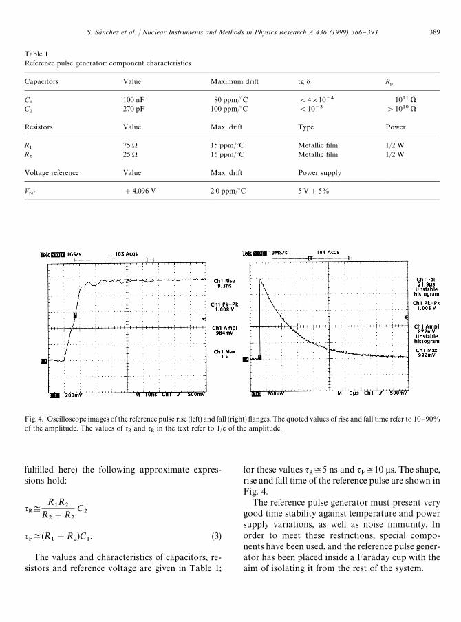
Table 1Reference pulse generator: component characteristics
Capacitors Value Maximum drift tg d R1
C1
100 nF 80 ppm/3C (4]10~4 1011 )C2
270 pF 100 ppm/3C (10~3 '1010 )
Resistors Value Max. drift Type Power
R1
75 ) 15 ppm/3C Metallic "lm 1/2 WR2
25 ) 15 ppm/3C Metallic "lm 1/2 W
Voltage reference Value Max. drift Power supply
V3%&
#4.096 V 2.0 ppm/3C 5 V$5%
Fig. 4. Oscilloscope images of the reference pulse rise (left) and fall (right) #anges. The quoted values of rise and fall time refer to 10}90%of the amplitude. The values of q
Rand q
Rin the text refer to 1/e of the amplitude.
ful"lled here) the following approximate expres-sions hold:
qR+
R1R
2R
2#R
2
C2
qF+(R
1#R
2)C
1. (3)
The values and characteristics of capacitors, re-sistors and reference voltage are given in Table 1;
for these values qR+5 ns and q
F+10 ls. The shape,
rise and fall time of the reference pulse are shown inFig. 4.
The reference pulse generator must present verygood time stability against temperature and powersupply variations, as well as noise immunity. Inorder to meet these restrictions, special compo-nents have been used, and the reference pulse gener-ator has been placed inside a Faraday cup with theaim of isolating it from the rest of the system.
S. Sa& nchez et al. / Nuclear Instruments and Methods in Physics Research A 436 (1999) 386}393 389
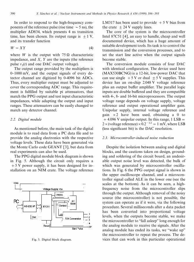
Fig. 5. Digital block diagram.
In order to respond to the high-frequency com-ponents of the reference pulse (rise time &5 ns), themultiplier AD834, which presents 4 ns transitiontime, has been chosen. Its output range is $1 V,and its transfer function
="X> (4)
where = is the output with 75 ) characteristicimpedance, and X, > are the inputs (the referencepulse l
2(t) and one DAC output voltage).
The output range provided by the multipliers is0}1000 mV, and the output signals of every de-tector channel are digitized by 0-4096 bit ADCs.Thus, every multiplier output must be adjusted tocover the corresponding ADC range. This require-ment is ful"lled by suitable pi attenuators, thatmatch the PPG output and test input characteristicimpedances, while adapting the output and inputranges. These attenuators can be easily changed tomatch any detector channel.
2.2. Digital module
As mentioned before, the main task of the digitalmodule is to read data from a PC data "le and toprovide the analog electronics with the respectivevoltage levels. These data have been generated viathe Monte Carlo code GEANT [3], but data fromreal experiments can also be used.
The PPG digital module block diagram is shownin Fig. 5. Although the circuit only requires a#5 V power supply, it has been designed for in-stallation on an NIM crate. The voltage reference
LM317 has been used to provide #5 V bias fromthe crate $24 V supply lines.
The core of the system is the microcontrollerIntel 87C51 [4], an easy to handle, cheap and welldocumented device, which has a huge amount ofsuitable development tools. Its task is to control thetransmission and the conversion processes, and toset the start line active when the output signalsbecome stable.
The conversion module consists of four DACwith identical con"guration. The device used here(MAX530BCNG) is a 12-bit, low-power DAC thatcan use single #5 V or dual $5 V supplies. Thisdevice has an on-chip 2.048 V voltage referenceplus an output bu!er ampli"er. The parallel logicinputs are double bu!ered and they are compatiblewith 4-, 8- and 16-bit microprocessors. The outputvoltage range depends on voltage supply, voltagereference and output operational ampli"er gain.Unipolar supply, internal voltage reference andgain ]2 have been used, obtaining a 0 to#4.096 V unipolar output. In this range, 1 LSB"
2](voltage reference)]0.2~12"1 mV, where LSB(less signi"cant bit) is the DAC resolution.
2.3. Microcontroller-induced noise reduction
Despite the isolation between analog and digitalblocks, and the cautions taken on design, ground-ing and soldering of the circuit board, an undesir-able output noise level was detected, the bulk ofwhich was generated by microcontroller oscilla-tions. In Fig. 6 the PPG output signal is shown inthe upper oscilloscope channel, and a microcon-troller signal called ALE in the lower one (see thescales at the bottom). As it can be seen, a high-frequency noise from the microcontroller slipsthrough the output. Although removal of the noisysource (the microcontroller) is not possible, thesystem can operate as if it were, via the followingprocedure. Several milliseconds after a data packethas been converted into proportional voltagelevels, when the outputs become stable, we makethe microcontroller to `fall asleepa long enough forthe analog module to receive the signals. After theanalog module has ended its tasks, we `wake upathe microcontroller to repeat the process. The de-vices that can work in this particular operational
390 S. Sa& nchez et al. / Nuclear Instruments and Methods in Physics Research A 436 (1999) 386}393
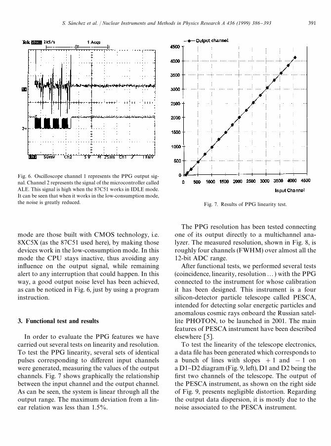
Fig. 6. Oscilloscope channel 1 represents the PPG output sig-nal. Channel 2 represents the signal of the microcontroller calledALE. This signal is high when the 87C51 works in IDLE mode.It can be seen that when it works in the low-consumption mode,the noise is greatly reduced. Fig. 7. Results of PPG linearity test.
mode are those built with CMOS technology, i.e.8XC5X (as the 87C51 used here), by making thosedevices work in the low-consumption mode. In thismode the CPU stays inactive, thus avoiding anyin#uence on the output signal, while remainingalert to any interruption that could happen. In thisway, a good output noise level has been achieved,as can be noticed in Fig. 6, just by using a programinstruction.
3. Functional test and results
In order to evaluate the PPG features we havecarried out several tests on linearity and resolution.To test the PPG linearity, several sets of identicalpulses corresponding to di!erent input channelswere generated, measuring the values of the outputchannels. Fig. 7 shows graphically the relationshipbetween the input channel and the output channel.As can be seen, the system is linear through all theoutput range. The maximum deviation from a lin-ear relation was less than 1.5%.
The PPG resolution has been tested connectingone of its output directly to a multichannel ana-lyzer. The measured resolution, shown in Fig. 8, isroughly four channels (FWHM) over almost all the12-bit ADC range.
After functional tests, we performed several tests(coincidence, linearity, resolution2) with the PPGconnected to the instrument for whose calibrationit has been designed. This instrument is a foursilicon-detector particle telescope called PESCA,intended for detecting solar energetic particles andanomalous cosmic rays onboard the Russian satel-lite PHOTON, to be launched in 2001. The mainfeatures of PESCA instrument have been describedelsewhere [5].
To test the linearity of the telescope electronics,a data "le has been generated which corresponds toa bunch of lines with slopes #1 and !1 ona D1}D2 diagram (Fig. 9, left), D1 and D2 being the"rst two channels of the telescope. The output ofthe PESCA instrument, as shown on the right sideof Fig. 9, presents negligible distortion. Regardingthe output data dispersion, it is mostly due to thenoise associated to the PESCA instrument.
S. Sa& nchez et al. / Nuclear Instruments and Methods in Physics Research A 436 (1999) 386}393 391

Fig. 8. PPg resolution (FWHM).
Fig. 9. (Left) Data "le used in the calibration of the PESCA instrument. (Right) Data acquistion with the PESCA instrument. Valueswith small amplitude are lost because they are under the telescope thresholds.
A similar test has been performed using datafrom a Monte Carlo simulation of the response ofPESCA instrument to an isotropic #ux of cosmicions. Detector thickness non-uniformity has beensimulated running many times GEANT with slight-ly di!erent detector thickness and small number ofevents. Each time, di!erent detector thicknesseshave been chosen randomly on a Gaussian distri-bution. The output "le of this simulation has beenused as pulse-amplitude data "le for the PPG, andthe pulses have been sent to PESCA electronics.A sample of both simulated events and events de-tected by the telescope can be seen on the left side of
Fig. 10 as D2}D
3scatter plot. A small o!set of
around 15 channels has been added to D2
andD
3data registered by the telescope. A magni"ca-
tion of this plot is shown on the right side of the"gure; the empty circles represent simulation data,and the black dots the data registered by PESCA.This small data portion corresponds to ions of thesame element (56Fe, in this case). As can be seen, thedistances between simulated and registered dataare very small when compared to the width of theline, due mainly to angular dispersion of trajecto-ries, energy straggling and thickness irregularities.Nevertheless, the main contribution to these small
392 S. Sa& nchez et al. / Nuclear Instruments and Methods in Physics Research A 436 (1999) 386}393
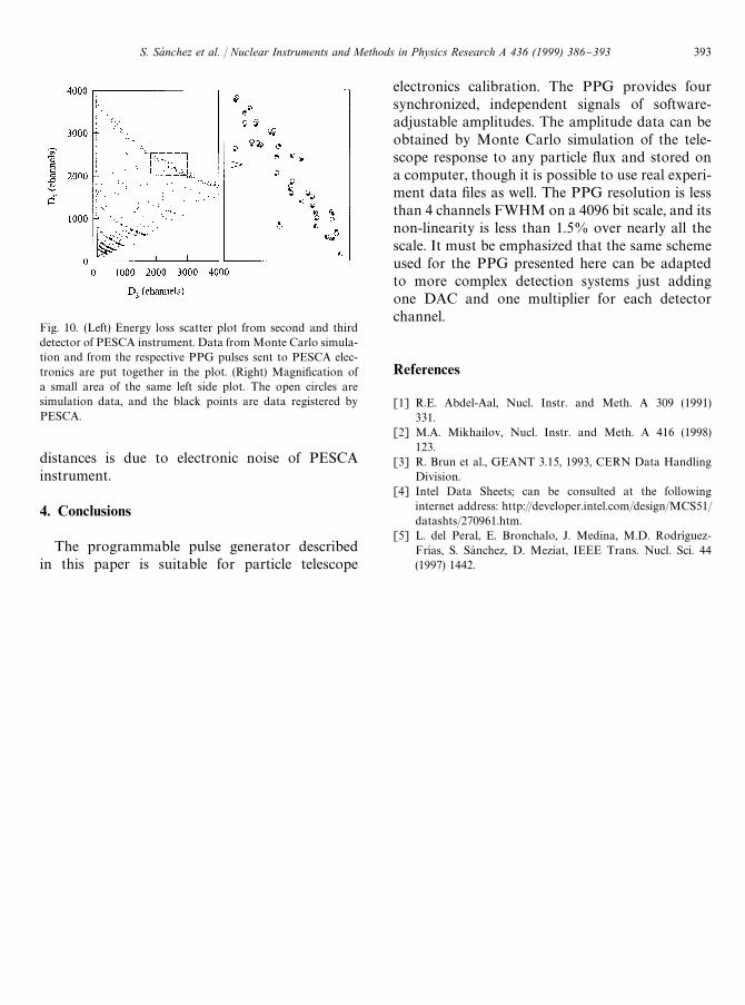
Fig. 10. (Left) Energy loss scatter plot from second and thirddetector of PESCA instrument. Data from Monte Carlo simula-tion and from the respective PPG pulses sent to PESCA elec-tronics are put together in the plot. (Right) Magni"cation ofa small area of the same left side plot. The open circles aresimulation data, and the black points are data registered byPESCA.
distances is due to electronic noise of PESCAinstrument.
4. Conclusions
The programmable pulse generator describedin this paper is suitable for particle telescope
electronics calibration. The PPG provides foursynchronized, independent signals of software-adjustable amplitudes. The amplitude data can beobtained by Monte Carlo simulation of the tele-scope response to any particle #ux and stored ona computer, though it is possible to use real experi-ment data "les as well. The PPG resolution is lessthan 4 channels FWHM on a 4096 bit scale, and itsnon-linearity is less than 1.5% over nearly all thescale. It must be emphasized that the same schemeused for the PPG presented here can be adaptedto more complex detection systems just addingone DAC and one multiplier for each detectorchannel.
References
[1] R.E. Abdel-Aal, Nucl. Instr. and Meth. A 309 (1991)331.
[2] M.A. Mikhailov, Nucl. Instr. and Meth. A 416 (1998)123.
[3] R. Brun et al., GEANT 3.15, 1993, CERN Data HandlingDivision.
[4] Intel Data Sheets; can be consulted at the followinginternet address: http://developer.intel.com/design/MCS51/datashts/270961.htm.
[5] L. del Peral, E. Bronchalo, J. Medina, M.D. RodrmHguez-FrmHas, S. SaH nchez, D. Meziat, IEEE Trans. Nucl. Sci. 44(1997) 1442.
S. Sa& nchez et al. / Nuclear Instruments and Methods in Physics Research A 436 (1999) 386}393 393