low cost large core vehicle structures assessment
TRANSCRIPT
207345
Low Cost Large Core Vehicle Structures Assessment
Final Report
for the period
November 1997 to March 1998
Contract H-28971D
Submitted to
NASA Marshall Spaceflight Center
March 13, 1998
Executive Summary
Boeing Information, Space, and Defense Systems executed a Low Cost Large Core Vehicle StructuresAssessment (LCLCVSA) under contract to NASA Marshall Space Flight Center (MSFC) betweenNovember 1997 and March 1998. NASA is interested in a low-cost launch vehicle, code named Magnum,
to place heavy payloads into low earth orbit for missions such as a manned mission to Mars, a NextGeneration Space Telescope, a lunar-based telescope, the Air Force's proposed space based laser, and largecommercial satellites. In this study, structural concepts with the potential to reduce fabrication costs were
evaluated in application to the Magnum Launch Vehicle (MLV) and the Liquid Fly Back Booster (LFBB)
shuttle upgrade program.Seventeen concepts were qualitatively evaluated to select four concepts for more in-depth study. The
four structural concepts selected were: an aluminum-lithium monocoque structure, an aluminum-lithium
machined isogrid structure, a unitized composite sandwich structure, and a unitized composite gridstructure. These were compared against a baseline concept based on the Space Shuttle External Tank (ET)construction. It was found that unitized composite structures offer significant cost and weight benefits to
MLV structures. The limited study of application to LFBB structures indicated lower, but still significantbenefits.
Technology and facilities development roadmaps to prepare the approaches studied for application toMLV and LFBB were constructed. It was found that the cost and schedule to develop these approaches
were in line with both MLV and LFBB development schedules. Current Government and Boeing programs
which address elements of the development of the technologies identified are underway. It is recommendedthat NASA devote resources in a timely fashion to address the specific elements related to MLV and LFBBstructures.

Magnum Launch Vehicle Program
L CL C VSA Program
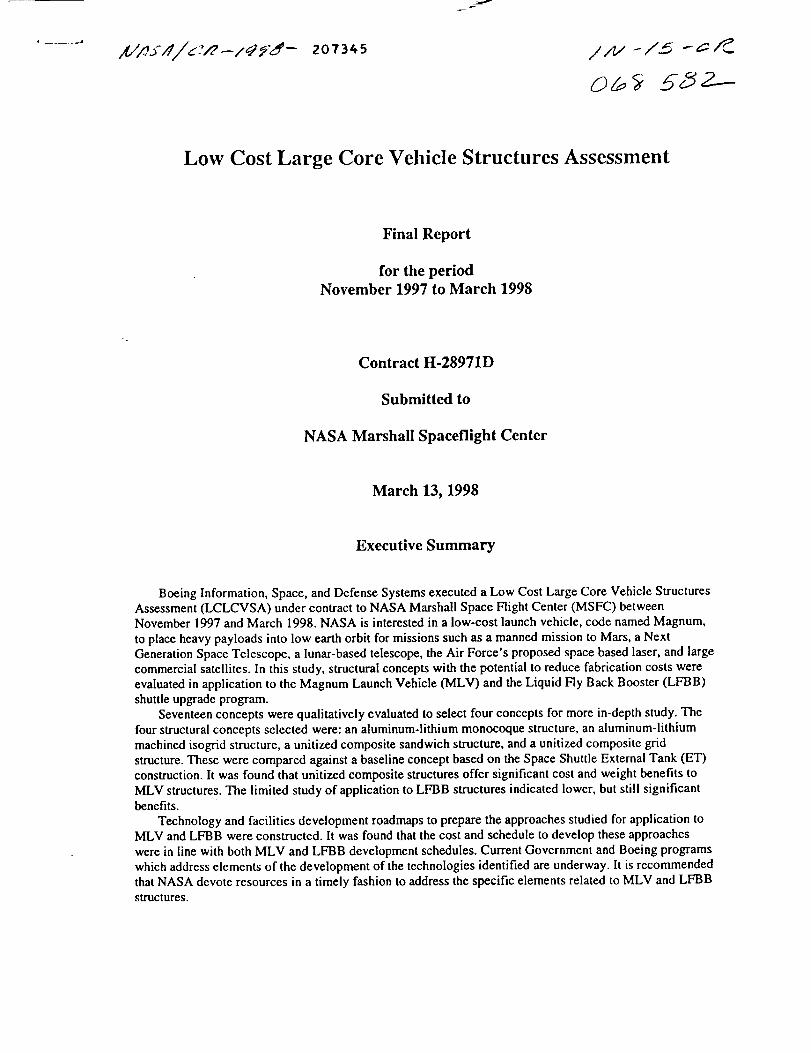
O Objective: Deliver large payloads to LEO usinglarge core Magnum Launch Vehicle (MLV)
O MLV supports missions such as:• Manned mission to Mars
- Place Mars mission hardware (8.4 m diameter x 30 mlong) weighing 80 metric tons into Earth orbit
- Approximately 6 MLV payload deliveries required tosupport I Mars mission
• Next Generation Space Telescope
• Proposed lunar-based telescope
• Air Force Space Based Laser
• Large commercial satellites
page 1 _L .XnEIA v'o i
NASA is currently developing preliminary plans for an expendablelaunch vehicle which can support future NASA and Air Force missions.The program is named the Magnum Launch Vehicle or MLV, and wouldbe primarily focused on a manned Mars exploration and developmentmission, but would be able to support additional missions including theNext Generation Space Telescope, the Lunar Telescope, the Air ForceSpace Based Laser, and large commercial satellites.
Page 1
Heavy Lift Launch Vehicle Technology
LCL C VSA Program
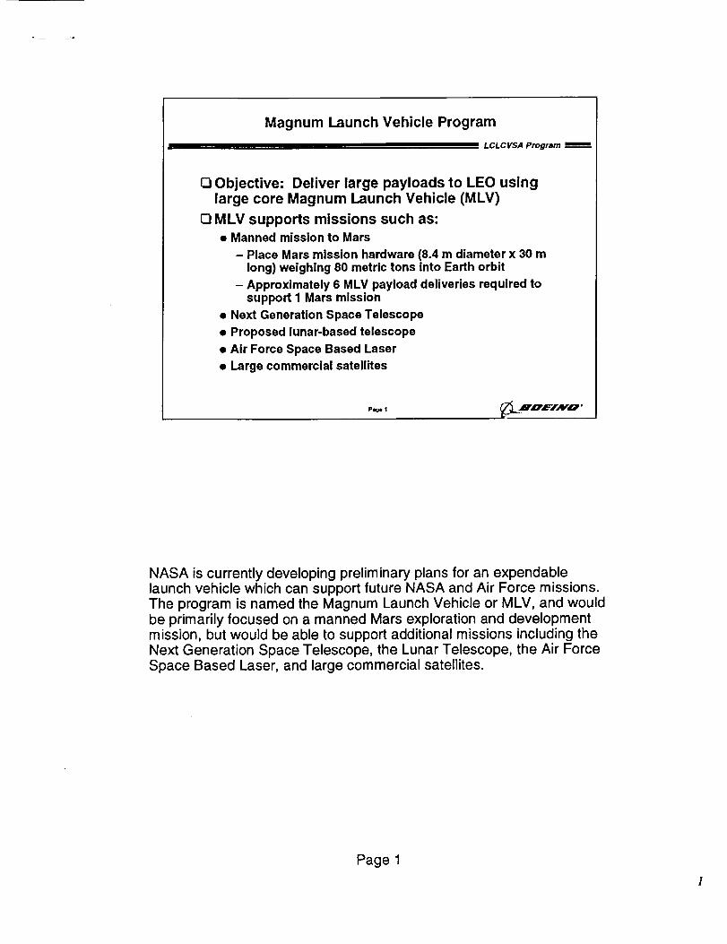
O Titan 4 is largest ELV in current US Inventory
• 16.7 ft. diameter x 86 ft. max length payload fairing
• Delivers about 22,000 kg to Low Earth Orbit (LEO)
• $250M-$450M per launch ($5000-$9000/!b)
O MLV Goals
• 27.5 ft. diameter x 128 ft. max length payload fairing
• Deliver 80,000 kg to LEO
• Approximately $175M per launch (<$1000/Ib)
P_ 2 ,m'DZ='IAFO '
The impetus for MLV development is driven by the lack of extremeheavy lift capability in the current US (and world) inventory. MLV hasfurther goals of significantly reduced cost while delivering a largerpayload to orbit.
Page 2
MLV Operations Approach Minimizes Costthrough Use of Existing Facilities
LCLCVSA Program
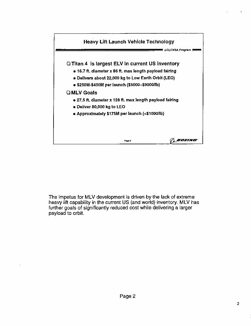
_3Final assembly at KSC in existing VehicleAssembly Building (VAB)• Structures fabricated at convenient facilities
• Barge transport to KSC
[] Maintain Shuttle SRB configuration• Identical attachment and tie down arrangement
• Use existing mobile launch platforms
• Use existing crawler-transporter
• Use modified pads 39A and 39B (new towers required)
• Optionally use Liquid Fly-Back Boosters (LFBB) insteadof SRB's
Pmge3 _LT__.HnEIHo '
The NASA concept for achieving MLV goals is to minimize operationscosts by utilizing existing infrastructure. This drives much of the vehicleconfiguration to match the current Shuttle layout, although plannedupgrades to the Shuttle (such as Liquid Fly-Back Boosters (LFBB) inplace of the Solid Rocket Boosters) are under consideration as well.
Page 3
3
Ih='lr_c'_m=
m =x= ,=,Jo =rj
I_fr&:E C,=,m
I,=_m== Lmmb
A v'a'= F Um_ Cam
GLOW
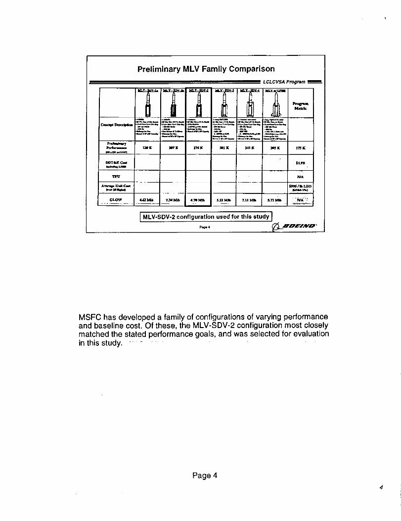
Preliminary MLV Family Comparison
ill_ .n.,M.= e_.m=.. .=
bJs
.m m,llb_
.,l_..t,v
.l.m_,.um
M! ILIK _K |76K
LCLCVSA Program _m
L: J- om.
.memr .li,mJ
HIE _K
4_ 7Jd_ 4._b $J_Mh 7o|1 ]HBIb
I MLV-SDV-2 configuration used for this study J
P_ 4
17'3 K
$1Jn
WA
f_J'J l Ib LEO
_'_M/m_J
MSFC has developed a family of configurations of varying performanceand baseline cost. Of these, the MLV-SDV-2 configuration most closelymatched the stated performance goals, and was selected for evaluationin this study.
Page 4
Core Vehicle Elements Similar
Across MLV Configurations
_#ood
Fwd _n
_nlrk
Ah S_
MLV SDV- la
2;3 2BOR,[ rEdO0 9200
2;'5 _f_27_ 4_•"75 2253
27.6 1175rr r exit EIP$
LCL C VSA Program
t . .;,,, "_'_Z" ]_"
' ";" s_m.
Ah EndYm_
Coro _ _ ET tooling
Core rd_Ine BnlulOemenf 4epend_'tf on m#ine o'lvelope
_ _bd roquirem_
6 dogree =quaro p= e_ _ gimb# a saJ'ned
Air _drf may require engtlo f_Hng_
SRB l Coro madn_Jh NSTS a#_cit potnts
)Od_ _o hte_rahl_ #110payload vo_c_nlo
page 5
305 It
Madr_ny / PD_]_4_ 7
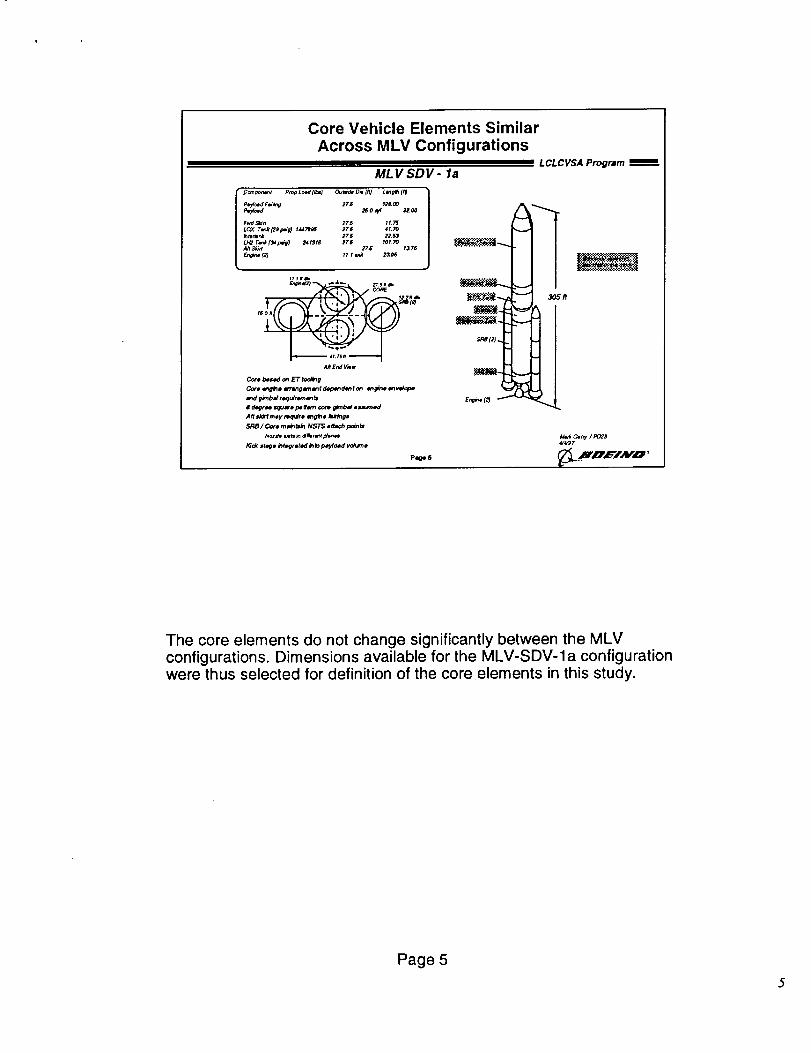
The core elements do not change significantly between the MLVconfigurations. Dimensions available for the MLV-SDV-la configurationwere thus selected for definition of the core elements in this study.
Page 5
Low Cost Large Core Vehicle StructuresAssessment Program Plan
LCLCVSA Program
E3Objective
• Assess low cost composite and metal approachesfor MLV core and LFBB structures
[_ Approach
• Task 1 - Concept Selection
- Select two metallic and two composite conceptsbased on potential to reduce cost
• Task 2 - Trade Study
- Evaluate cost and weight Impact of the selectedconcepts on MLV core structures
• Task 3 - Development Roadmap
- Identify technology and facilities advancesneeded to enable low cost MLV structures
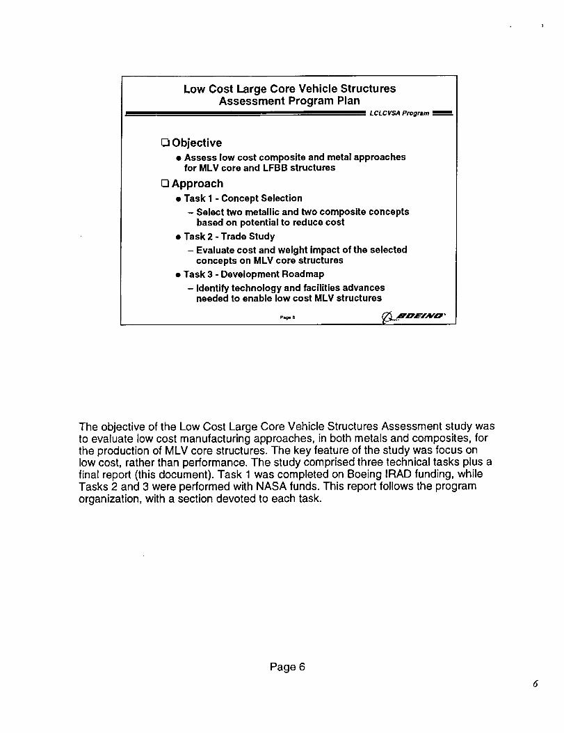
The objective of the Low Cost Large Core Vehicle Structures Assessment study wasto evaluate low cost manufacturing approaches, in both metals and composites, forthe production of MLV core structures. The key feature of the study was focus onlow cost, rather than performance. The study comprised three technical tasks plus afinal report (this document). Task 1 was completed on Boeing IRAD funding, whileTasks 2 and 3 were performed with NASA funds. This report follows the programorganization, with a section devoted to each task.
Page 6
6
LCLCVSA Team
• LCLCVSA Program
_o Bob Porter• S=an Spencer I" T;rm°gMmarmIManager
r • David Ander,on
i • i co Princt_DalInvestigator / "Co-Principal Investigator I D[
L " Structur" De$igrl p
_Br_"_Van WestI • I -Jim Co(ton Ill
I - Mfg. R&D
__ r- Tom Derbyshire
PFTI
I• I _ Jeff Cannon Ill
__ L -SystermEngr PI I.RwP°_" _
I I ° John Pulley JIe I st==,=_LFBe
__- Boeing, Downey, CA
Page 7
0 Integrated ProductTeam organization
0 Participation fromacross the new Boeing
• Broad experience inlaunch vehicles,advanced technology
[] Direct Customer
participation
• Ensure utility of results
_L jnz=TAvo
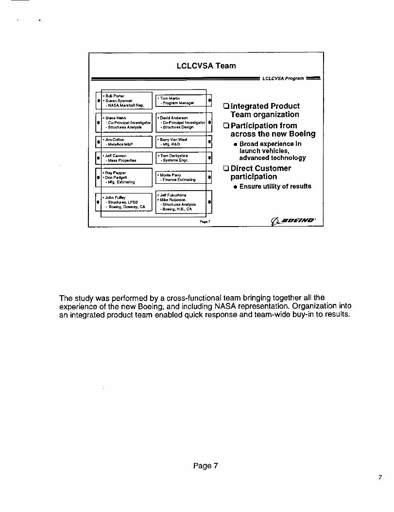
The study was performed by a cross-functional team bringing together all theexperience of the new Boeing, and including NASA representation. Organization intoan integrated product team enabled quick response and team-wide buy-in to results.
Page 7
?
Executive Summary of Results
L CL C VSA Program
[_ Composite structure concepts which utilize large,unitized construction were found to reduce both
cost and weight
Primary cost drivers were identified for eachconcept which could be reduced throughtechnology and facilities advancements
C3Investment roadmaps for technology and facilitiesimprovements were developed
Q Reduction of structures costs was found to be animportant step towards achieving NASA goals forMLV cost performance
Page @ __.H, OW'iAV',O''
It was discovered that large, unitized composite structures reduced boththe weight and cost of MLV core structures. Specific cost drivers foreach concept studied were identified which had further cost reductionpotential through the application of advanced technologies. Roadmapsfor development of these technologies and the facilities to implementthem on an MLV scale were produced.
Overall, it was found that significant reductions in structural fabricationcost could be achieved, and that these cost savings would translate intosignificant savings at the vehicle level. However, these structural costsavings alone were insufficient to achieve the stated NASA goals forMLV.
Page 8
Task I - Concept Selection
LCL C VSA Program
Section Topics:
C3Attributes of low cost structure
Material, manufacturing, and structural
configuration options
O Potentially high payoff concepts
Rating process
D Selection results
Page9 _L .m,n,c=-i,_vo,
This space intentionally left blank.
Page 9
9
Potential Payoff Cost Attributes
I III I L CL C VSA Program
O Minimize Part Count
• Standardize, Reuse of Components
• Low part count designs
O Minimize Manufacturing Flow
• Standardize and Optimize Processes• Automate Processes
O Eliminate or Simplify Tooling
• Standardize or Reuse of Tooling
• Soft Tooling, Built in Tooling, etc.
O Reduce Inspection with Reliable Processes
O Minimize New Capital Equipment
Page 10 __.N,e'EIAv'o •
The initial task was to identify those attributes of a manufacturingapproach which would tend to reduce cost. Primary among these wasthe reduction of the number of parts in a design. This reduces directtouch labor in part fabrication and assembly, and also reduces designand development costs. Additional considerations were reduction ofprocessing steps, tooling simplification, inspection reduction, andminimization of capital equipment requirements.
Page 10
lo
Material, Manufacturing, and StructuralConfiguration Options
n LCLCVSA Program
C qmposlte Specific OptionsBJe_J• Low mOd,Jul -250_ F
• 360_ F• Imel_oClal,modulus . I_ _o1_
• GIm . Low T6e_ (v, fl_-• KoV4t _m_ng _C_u_o)
• E_,w_ in/lietod
• Fub_c
• T_ -kvlr• Tow • PJum_,_,m
• P4A _o'r4r.Wood
•Fce, m
• Ca_lour _ I,,y_o m,Bo'_e (CTLU} • Bui_in t:x:f_g
• D_ [<x_cna _. _,._• F_l_aenl vindleg
• l_be_ _,_.,_
• P4_ I_ • Mech_c_
• SCRIMP _6_
•Reeb te,md,_ mold'_9(RTM ) •Adh_ bo_dng• _ r,lm ;nrumon _1:1) • C<cu_dx, rd
• ;nduct;on mid
• Vscu_m b_rc_n • Inledo_n_• InduCl_ oum
• Low temp cure
_letal Specific Options
•/¢-2XXX
• N-TXXX
-.N4J
_=rmlne_M_h_._ Pr c_ew
• Tre6ulo_/_ oh_ng
• l_gh =p_d m=cr, ning• n_l fo_g
• Bump_ _k to_ing
• 51mt:_ fo_it_g
• Stff_ed p_ _m_m
.H_g• F'ua=d to,rig
• c_ _or_v• So# too_g
.Wd6ng• GTAW
• VPPA w(4d_ 9• LJ_w_ld_ 9
• Adhe_w boring
• Br_zlng
Stiffenincl OptionsI "_ "Oc'nug_d_l S_llen_O
• Ho_e/=omb _ * Angk, d-gd_
• T_4I corn
p_e 11 _.Ru, e'/AY,a •
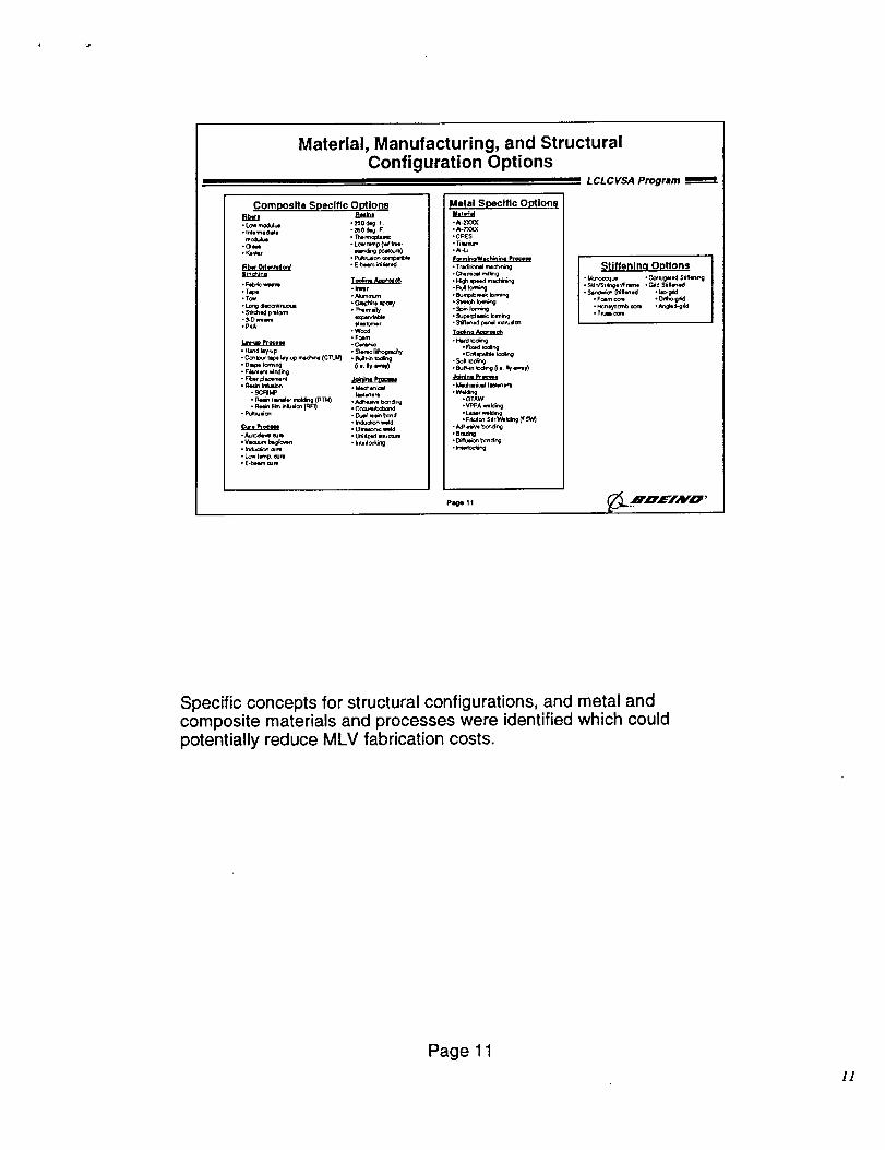
Specific concepts for structural configurations, and metal andcomposite materials and processes were identified which could
potentially reduce MLV fabrication costs•
Page 11
I!
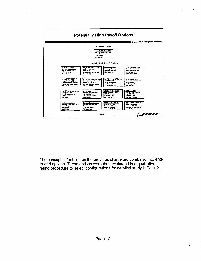
Potentially High Payoff Options
L CL C VSA Program
Bezellna Option
1' IPotentially High Payoff Options
P_gh =pe_d macNr_ng C._Ep<my I<xtm mnd_oh k_=gra_f *l_ed p_ Odd IJlonod un_z_ I_l_Hzn_ kzy,up ,Numlnum _uJcn Nb_r pl_d GdEpc_
8_,_n t0di_l Foam ICing
'i S_IO%_ pmloml, _PJMP Fit:4r plamod (_l_Epoxy | CO-¢Uf_KI _(llenem Bump Iormed
E-bMm cure _r vmcuum 360 d_ F. _u_o¢_ cu_ I Low _p aulOdev_ our= W_ded mmmt_'
iiP10SPFConL<=oledPllt_liS PF/_he _'ve bond N_Li Pu_uded (_t_ po_yFSW memUy i _q_oe_in_ _.mml_
Page 12
I ,%,
The concepts identified on the previous chart were combined into end-to-end options. These options were then evaluated in a qualitativerating procedure to select configurations for detailed study in Task 2.
Page12
]2
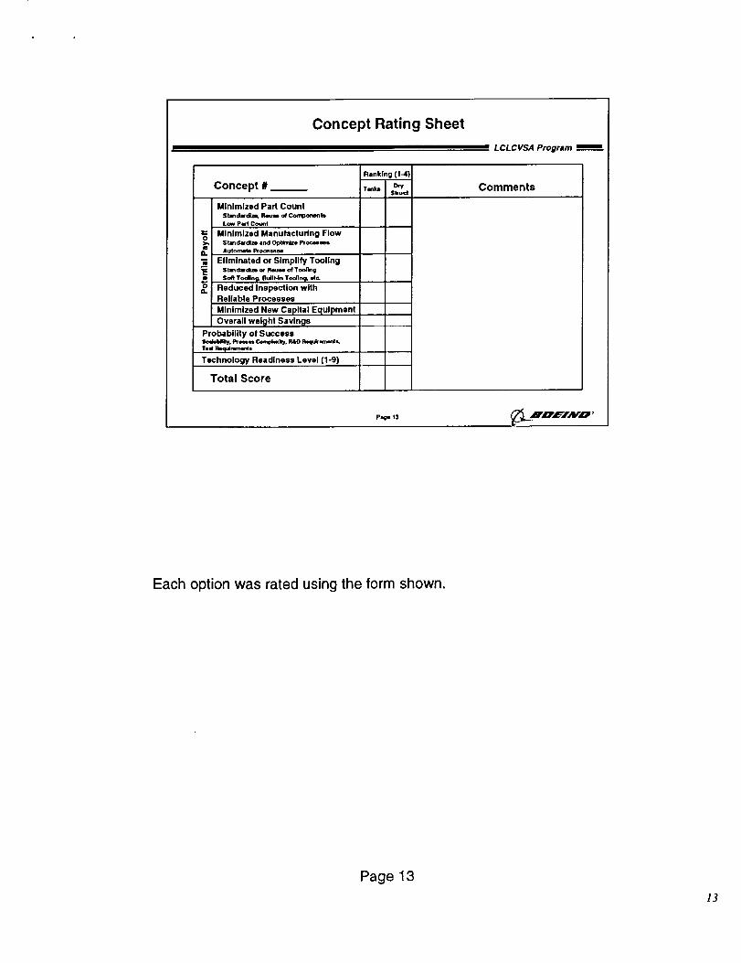
Concept Rating Sheet
L CL C VSA Program
Concept #
Minimized Part Count
Stmdacdl_, I_ o_Cort_onenllLow PactCount
Minimized Manufacturing FlowStandwdlze and Optln_e Pfoc_m
i_ Automato Proces_N
Eliminated or Simplify Tooling
_e St_dardlm or Reu_ of ToollngSoft Toolln_. Built-in Tooling, err.
o Reduced Inspection with
Reliable Processes
Minimized New Capital Equipmeni
Overall weight Savln_ls
Probability of Success
Technology Readiness Level (I-9)
Total Score
Ranking (!-4)
Tmb D_Sbud
Comments
page t3
Each option was rated using the form shown.
Page13
]3
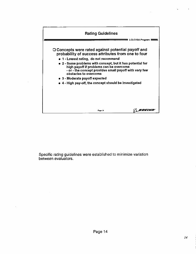
Rating Guidelines
LCLCVSA Program
[_ Concepts were rated against potential payoff andprobability of success attributes from one to four
• 1 - Lowest rating, do not recommend
• 2 - Some problems with concept, but it has potential forhigh payoff if problems can be overcome- or - the concept provides small payoff with very fewobstacles to overcome
• 3 - Moderate payoff expected
• 4 - High pay-off, the concept should be investigated
Pooe 14
Specific rating guidelines were established to minimize variationbetween evaluators.
Page 14
]4
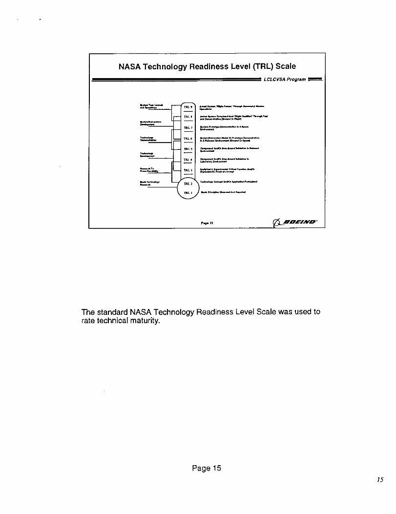
NASA Technology Readiness Level (TRL) Scale
L CL C VSA Program
=.*d_
T=W_nak,W
lr.x_,.,,kw
_m
TRL9
TELl
TRL 7
TRL6
• . _ ___I_
TIlL I
k_,bm
k, WW
pa=ge 15
The standard NASA Technology Readiness Level Scale was used torate technical maturity.
Page 15
]5
Weighting Factors Applied to Ratings
LCL CVSA program
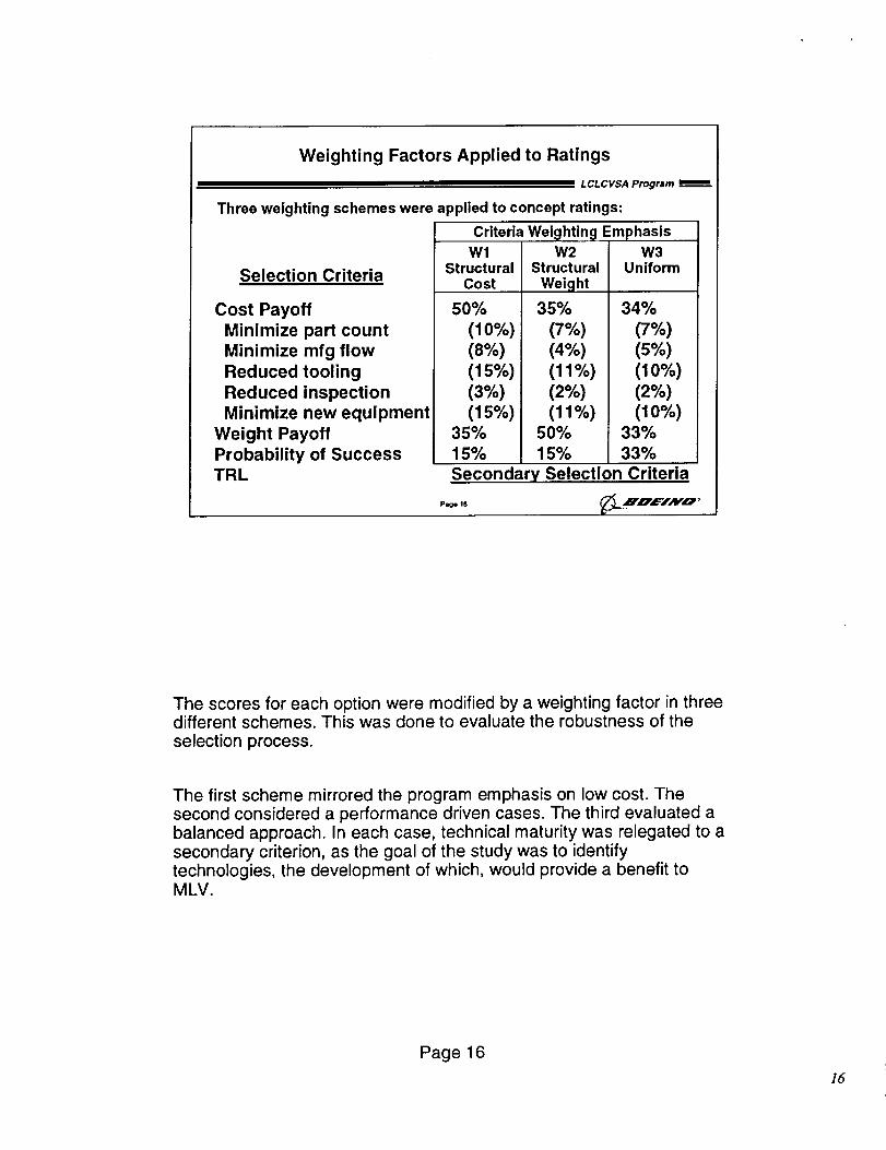
Three weighting schemes were applied to concept ratings:
Selection Criteria
Cost Payoff
Minimize part countMinimize mfg flowReduced tooling
Reduced inspectionMinimize new equipment
Weight PayoffProbability of SuccessTRL
Criteria
WlStructural
Cost
5O%
(10%)(8%o)(15%)(3%)(15%)
35%15%
Wei_lhtin_! EmphasisW2
StructuralWeight
35%
(7%)(d%)
(11%)(2%)(11%)
50%15%
W3Uniform
34%
(7%)(5%)(10%)(2%)(10%)
33%33%
Secondary Selection Criteria
The scores for each option were modified by a weighting factor in threedifferent schemes. This was done to evaluate the robustness of the
selection process.
The first scheme mirrored the program emphasis on low cost. Thesecond considered a performance driven cases. The third evaluated abalanced approach. In each case, technical maturity was relegated to asecondary criterion, as the goal of the study was to identifytechnologies, the development of which, would provide a benefit toMLV.
Page 16
16
Compiling Concept Ratings
LCL C VSA Program
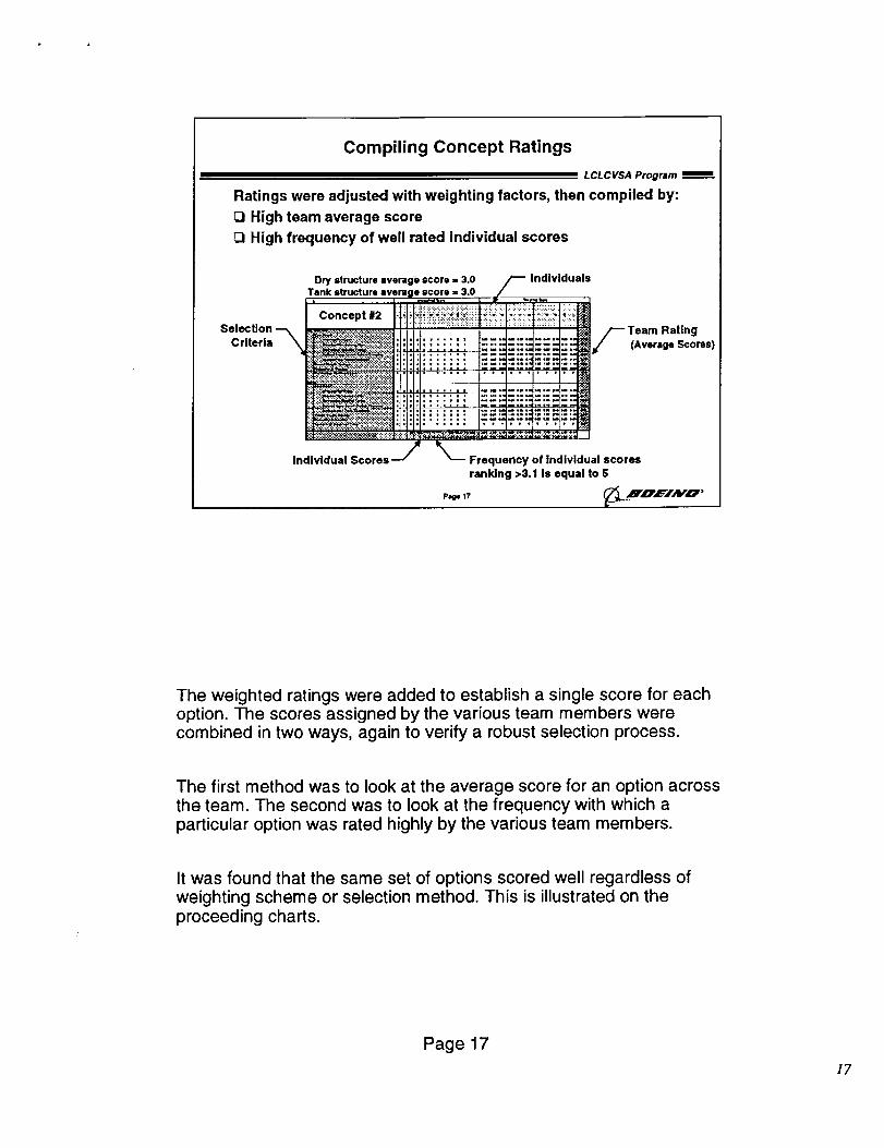
Ratings were adjusted with weighting factors, then compiled by:
O High team average score
_1 High frequency of well rated Individual scores
Dry structure avarago score ,, 3.0 /-- Individuals
Tank structure average $corj = 3.0 it/ ....
Concept #2 :: i i _::i_i_i_:._i::ii::_:::::ilii_::::.!::__!::i_!:::.::_::i:::.::i_:i!:
Selection-_ ._i_: j , /_Tearn RatlngCriteria _" :: [_ii:: t._'--"_'i_".--'._'--';_'[]/ (AvsrageScorss)
ranking >3.1 is equal to 5
P_, 17 _.._F,O',L='/AIrO '
The weighted ratings were added to establish a single score for eachoption. The scores assigned by the various team members werecombined in two ways, again to verify a robust selection process.
The first method was to look at the average score for an option acrossthe team. The second was to look at the frequency with which a
particular option was rated highly by the various team members.
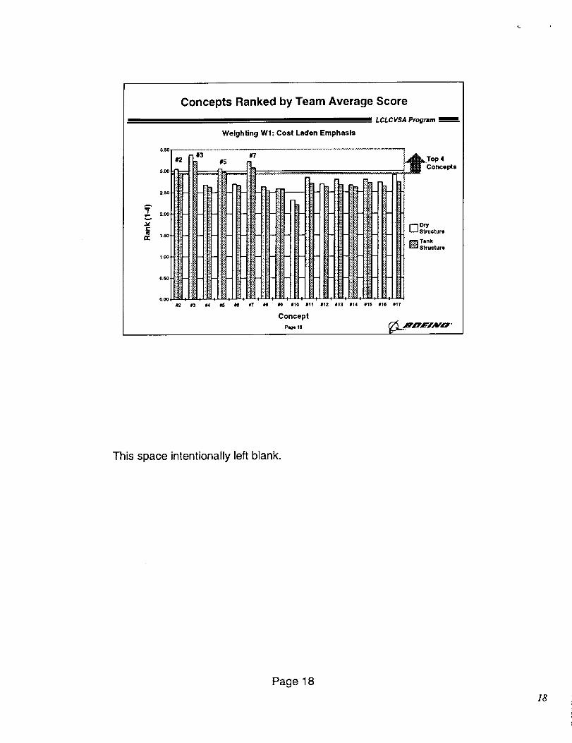
It was found that the same set of options scored well regardless ofweighting scheme or selection method. This is illustrated on theproceeding charts.
Page 17
]7
£:
#
3+501
3.00
2.5O
1,50
1+00
0.50
0.00
Concepts Ranked by Team Average Score
LCL C VSA Program
WelghUng WI: Cost Laden Emphasis
#7 1 _1_ T 4
ii III FHIHtHIiHLHI;HII......07,%,,,,.
4 ltf, , t!:lT-'J, [_:l:-t, I f-':l, I _ 1
li2 i3 M 15 _ ll7 i8 H illO #11 1112 it3 114 I15 116 lilt7
Concept
P-i- ill _._..._i'LP, L='/N,I_ I>
This space intentionally left blank.
Page18
]8
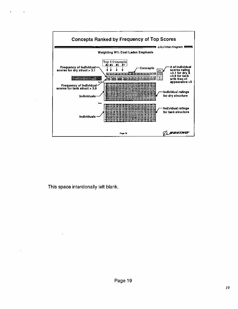
Concepts Ranked by Frequency of Top Scores
L CL C VSA Program
WeighUng WI: Cost Laden Emphasis
iTop ,t Concepts I: |=..._r2,.r_...._5..../tT...,
Frequency of indlvidual_ / / / / _--Concents /---# of Individualscores for dry struct > 3.1\ _ _ _ _ _.. _/ " _j¢' scores rating
_,:_:-_;-_,.-_-_,-:_.-:-:.-_-;_-:.,-:_:._,:._,._-.. _ >3.1 for dry _,>3.0 |or tank
.,-,- _ appearance >5.__ ' :..'>__-:.'_..: ._ _._.- _ :.<.._.._i_:.._.'_:_.-._.
Frequency of Indlvldual I:_,_N:._NA_}._._,.e:NN_:,_-:N:._x4_-..-T._., :.,_:._ : . :)._: .: . _:_.-;.. ;.'_:.:_:_:_scores for tank struct > 3.0 i ,r_:,_:_._!_.._._:_.:$_._:...:..-v:_j
* .'_:"3_$'_:_..__ ": :! "!_:¢t$::_..:¢ ;..¥...:_: :_._ ':_._i_'_i_i_:_:_:¢_#'_:_:_ _ Individual raU ngs
Individuals J I:_;_i_{_iN_iNi_Nl_!_..._)_ for dry structure,o -T._._.'_r_.:"_¥:._:."._:_:.-..'_. :_. : :_.-._.:T.._.T.._.¥.._.:_._.:...
.'. _._t)Ag. . " .... " "" "=" ":"$_-_;=-_Y_."._'_.'._i=_ ...... _" _:i:_:_ "/,_,_,_,___/_Indlvldual ratings
,,I, E_-__.'-_"._._:._.'._-_._.".*._?_ _'._._ _: _,Z _^, _,, z, ,_,,, ,c h ,-e, ._*._,_--_,_I_. .. _'_._.'_
• .,... : ........ ._._. . _ • ._,_'. <_ ._:.
p_ge 19 _;_L.HnE/A v'o"
This space intentionally left blank.
Page19
]9
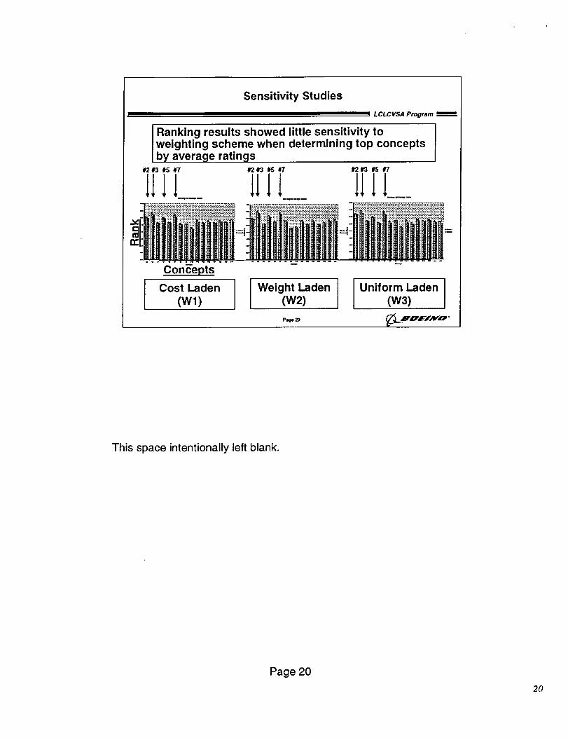
Sensitivity Studies
LCL C VSA Program
Ranking results showed little sensitivity toweighting scheme when determining top conceptsby average.ratings
#2 r3 #S #7 #2 #3 #5 #7 #2 #3 #5 #7
1111.... 1111.... 1111...._ ":: :::::::"::::::::::::::::::::::::::::::::::::::::::::::::::::::::::::: ::::: :i::i""::i:!:i: :_.'.::_:!:_:_-_:i:!::!:i:!::!:.::!::.:_:.::!::_:.::i:.::i:-:_- : :::"::::: ===============================================
Conc'epts
I Cost Laden(Wl) J Weight Laden(w2) I I unif°rm Laden(W3) J
Pzge 20 _',u,_JAYO '
This space intentionally left blank.
Page 20
20
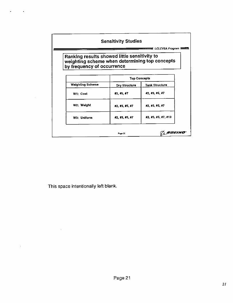
Sensitivity Studies
LCLCVSA Program mere
Ranking results showed little sensitivity toweighting scheme when determining top conceptsby frequency of occurrence
WeighUng Scheme
Top Concepts
Tank StructureDry Structure
#3, #5, #7Wl: Cost #2, #3, #5, #7
W2: Weight #2, #3, #S, #7 #2, #3, #5, #7
W3: Uniform #2, #3, #5, #7 #2, #3, #S, #7, #13
Page 21 7<__.Hn',L':'INO '
This space intentionally left blank.
Page 212]
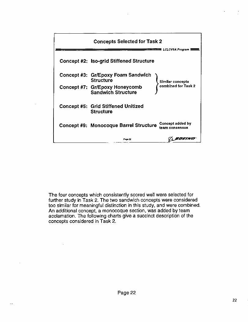
Concepts Selected for Task 2
LCLCVSA Program
Concept #2: Iso-grid Stiffened Structure
Concept #3:
Concept #7:
Gr/Epoxy Foam SandwichStructure
Gr/Epoxy HoneycombSandwich Structure
Similar concepts
combined for Task 2
Concept #5: Grid Stiffened UnitizedStructure
Concept #9: Monocoque Barrel Structure Concept added byteam consensus
The four concepts which consistently scored well were selected forfurther study in Task 2. The two sandwich concepts were consideredtoo similar for meaningful distinction in this study, and were combined.An additional concept, a monocoque section, was added by teamacclamation. The following charts give a succinct description of theconcepts considered in Task 2.
Page 22
22
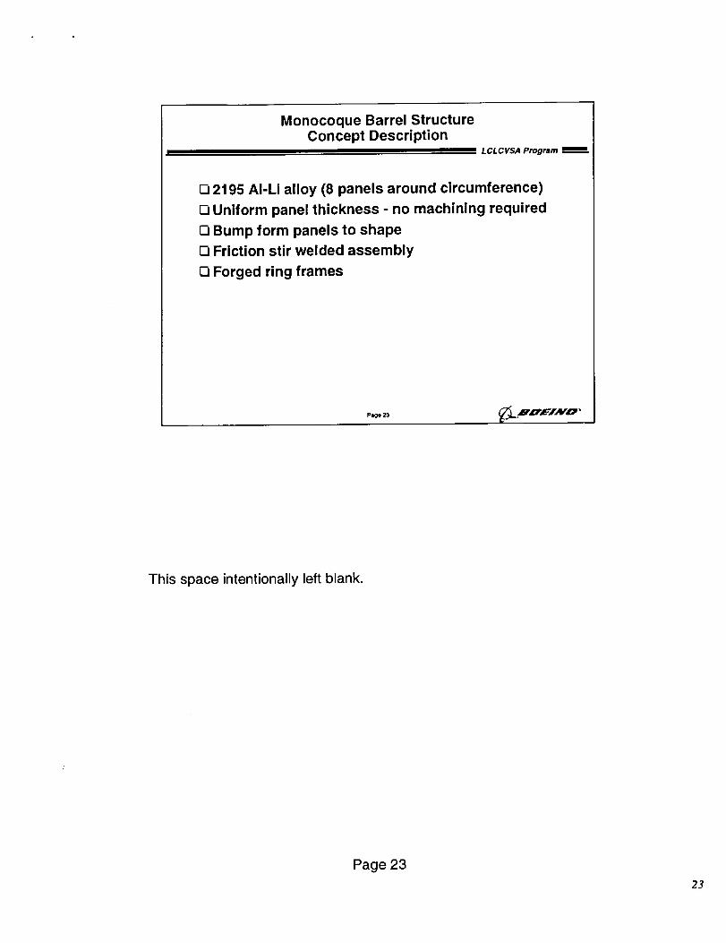
Monocoque Barrel StructureConcept Description
LCLCVSA Program
[] 2195 AI-Li alloy (8 panels around circumference)
[] Uniform panel thickness - no machining required
O Bump form panels to shape
[] Friction stir welded assembly
[] Forged ring frames
PI,ge 23 _L .HZz'EIAV'O '
This space intentionally left blank.
Page 23
23
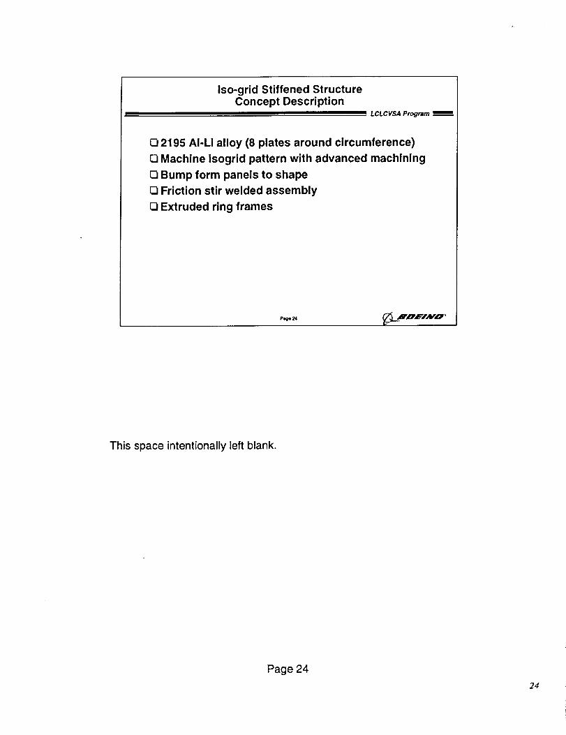
Iso-grid Stiffened StructureConcept Description
LCLCVSA Progrmm _-
O 2195 AI-Li alloy (8 plates around circumference)
O Machine isogrid pattern with advanced machining
O Bump form panels to shape
Friction stir welded assembly
O Extruded ring frames
Page 24
This space intentionally left blank.
Page 24
24
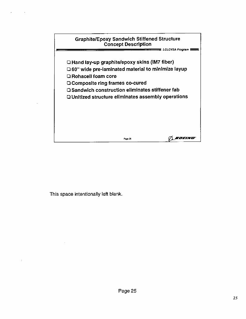
Graphite/Epoxy Sandwich Stiffened StructureConcept Description
LCLCVSA Program __
[] Hand lay-up graphite/epoxy skins (IM7 fiber)
[] 60" wide pre-laminated material to minimize layup
[] Rohacell foam core
[] Composite ring frames co-cured
Sandwich construction eliminates stiffener fab
[] Unitized structure eliminates assembly operations
Page25 _B'D,L='IAFO '
This space intentionally left blank.
Page 25
25
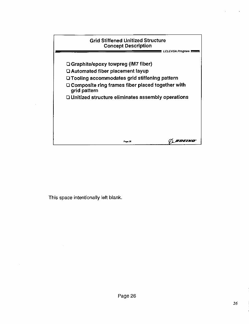
Grid Stiffened Unitized StructureConcept Description
L CL C VSA Program
Graphite/epoxy towpreg (IM7 fiber)
Q Automated fiber placement layup
Q Tooling accommodates grid stiffening pattern
O Composite ring frames fiber placed together withgrid pattern
D Unitized structure eliminates assembly operations
Page 2@LNLVEJNO,
• o, ,
This space intentionally left blank.
Page 26
26
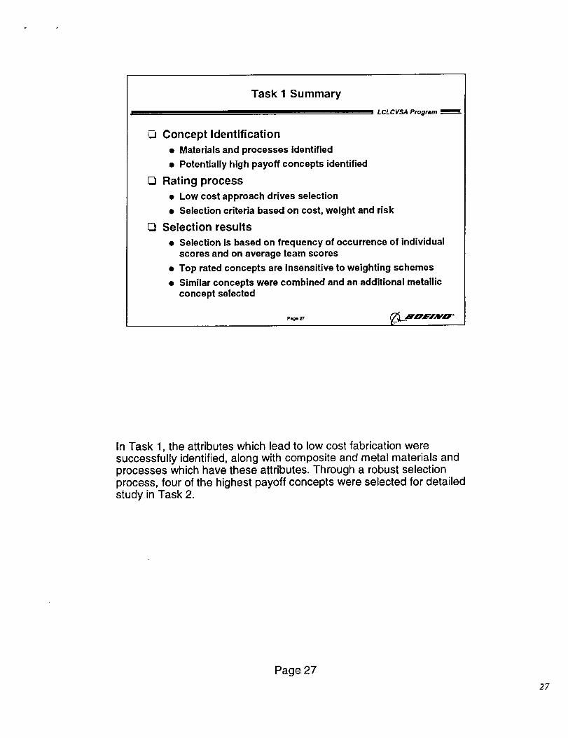
Task I Summary
LCLCVSA Program
(_ Concept Identification
• Materials and processes identified
• Potentially high payoff concepts identified
Rating process
• Low cost approach drives selection
• Selection criteria based on cost, weight and risk
[_ Selection results
• Selection is based on frequency of occurrence of individualscores and on average team scores
• Top rated concepts are insensitive to weighting schemes
• Similar concepts were combined and an additional metallicconcept selected
pl_e 27
In Task 1, the attributes which lead to low cost fabrication weresuccessfully identified, along with composite and metal materials andprocesses which have these attributes. Through a robust selectionprocess, four of the highest payoff concepts were selected for detailedstudy in Task 2.
Page 27
27
Task 2 - Trade Study
Section Topics:
O MLV core trade study
• Loads and requirements
- Typical requirements- LCLCVSA subset
- Thermal, acoustic, and mechanical loads
• Material properties
• Structural sizing and design summaries
• Vehicle resize and weight estimates
• Cost estimates
O Thrust structure assessment
O LFBB assessment
Page 28
L CL C VSA Program
Task 2 comprised structural definition and weight and cost estimation activities to
support a trade study between the four concepts selected in Task 1.
Page 28
28
ALS LH 2 Tank Requirements
Functional Requirements
LCLCVSA Program
Provide Support
• Contain pressurized LH2• Transfer primary loads• Cable trays and L02 feedlim
• Range safety components• Antivortex and slosh baffles
bolt strainer, fluid level_nSOl_
• Ground handling
Provide Access
• Tank interior
Provide EavironmentalControl• Contain LH2 with
acceptable boiloff• Maintain cleanliness
of LH2
Provide Interfaces
• Cable trays and lines• Range safety systems• Fluid supply, vent and
pressurization systems• Ground handling• Intertank and thrust
structure
Servieability
• Low cost repairfeatures
• Inspectability
Design Requirements
• Provide strength for primary structural loads• Provide thermal environment for containment of LH2
Forward dome, -205"1::- Aft dome, -423"F
• Proof test each tank
- Proof te.st = 35.5 psig (both)
- 1.05 rain proof factor- Hydrostatic, ambient temperature- Based on MEOP at T = 125 see
• Propellant suppression control
P.o- 2g _ .JT,_ ',¢_/A 1¢O '
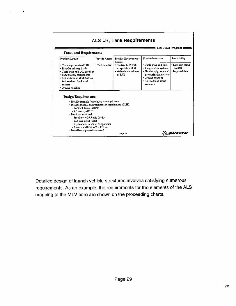
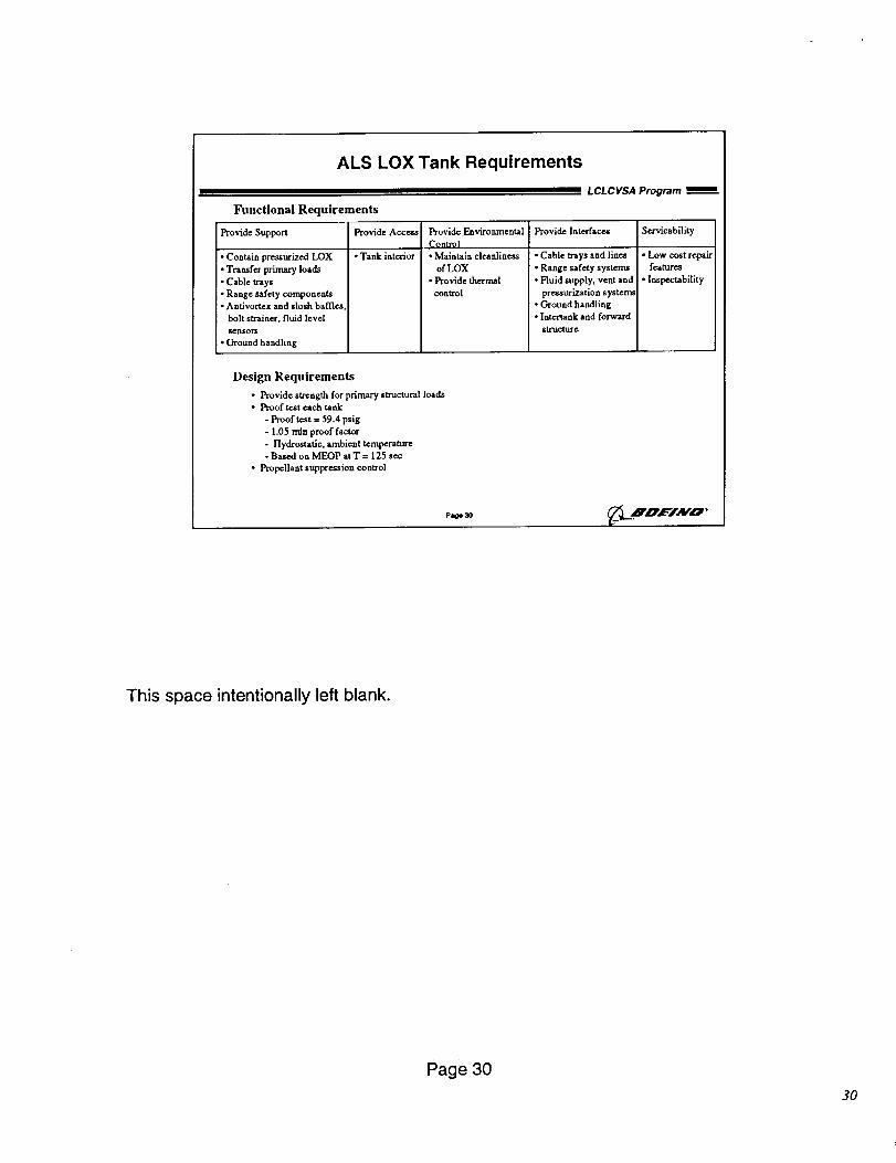
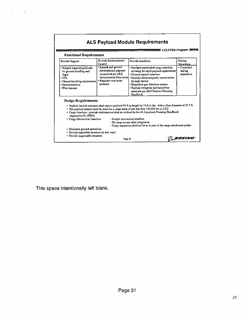
Detailed design of launch vehicle structures involves satisfying numerous
requirements. As an example, the requirements for the elements of the ALS
mapping to the MLV core are shown on the proceeding charts.
Page 29
29
ALS LOX Tank Requirements
Functional Requirements
Provide Support
• Contain pressurized LOX• Transfer primary loads
• Cable trays• Range safety components• Antlvortex and slosh baffles
bolt strainer, fluid level
ge[l$OI_
• Ground handling
Provide Access
• Tank interior
Provide EnvironmentalControl• Maintain cleanliness
of LOX• Provide thermalcontrol
LCLCVSA Program _=
Provide Interfaces Servicability
• Cable trays and lines• Range safety systems
• Fluid supply, vent andpressurization systenu
• Ground handling• lntertank and forward
structure
• Low cost repairfeatures
• lnspectability
Design Requirements
• Provide strength for primary structural loads• Proof test each tank
- Proof test = 59.4 psig
- 1.05 rain proof factor- Hydrostatic, ambient temperatm¢- Based on MEOP at T = 125 sec
• Propellant suppression control
page 30 Ak"O '
This space intentionally left blank.
Page 30
3O
ALS Payload Module Requirements
LCLCVSA Program
Functional Requirements
Provide Support Provide Environmental Provide InterfacesControl
• Adapter supports payloads
for ground handling and
flight•TPS
• Ground handling attachments• Instrumentation
• Wire harness
• Launch and ground
environments imposed
on payload per ALS
Eavironments Data book
• Regulate vent boost
pfe_xa'e
• Standard mechanical cargo interface
allowing for rapid payload replacement
• Ground support interface
• Payload electromagnetic transmission
through shroud
• Hazardous gas detection system
• Payload cryogenic and hazardous
materials per ALS Payload Planning
Handbook
Pairing
Separation
• Controlled
fairing
reparation
Design Requirements
• Payload module structure shall carry a payload 80 ft in length by 15 ft in dis., with a clear diameter of 27.5 R.
• The payload adapter shall be rated for a cargo mass of not less than 100,000 lbs to LEO• Cargo Interface - provide minimum services as outlined in the ALS payload Planning Handbook
(Appendix IV) (TBD)
• Cargo Mechanical Interface - Simple mechanical interface
- No cargo access after integration
- Cargo separation shall not be at or part of the cargo attachment points
• Minimize ground operations
• Provide repairable structure (st low cost)
• Provide iuspectable structure
P .o. 31 (/',I.._'_,_INO"W
This space intentionally left blank.
Page 31
31
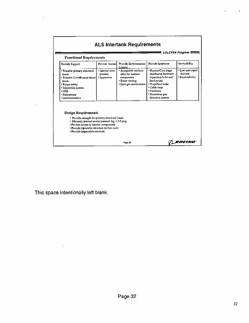
ALS Intertank Requirements
LCLCVSA Program
Functional Requirements
Provide Support Provide Access Provide Interfaces Servicability
• Transfer primary structural
loads
• Transfer Core/Booster thrust
loads
• Range safety
• Separation system
• GSE
• Subsystems
• Instrumentation
• Internal com-
ponents
• Inspection
Provide Environmental
Control
• Acceptable environ-
ment for internal
components
• Boost venting
• Inert gas environment
• Booster/Core stageattachment hardware
separation bolts and
hard points
• Propellant tanks
• Cable Ways
• Feedlines
• Hazardous gas
detection system
• Low cost repair
features
• lnspectability
Design Requirements
• Provide sb'ength for primary structural loads
• Maintain internal ascent pressure lag < 1 0 psig
• Provide access to interior components
• Provide repairable structure (at low cost)
• Provide inspectable structure
Pao*_ __ Rzrz_-i.tvo,
This space intentionally left blank.
Page 32
32
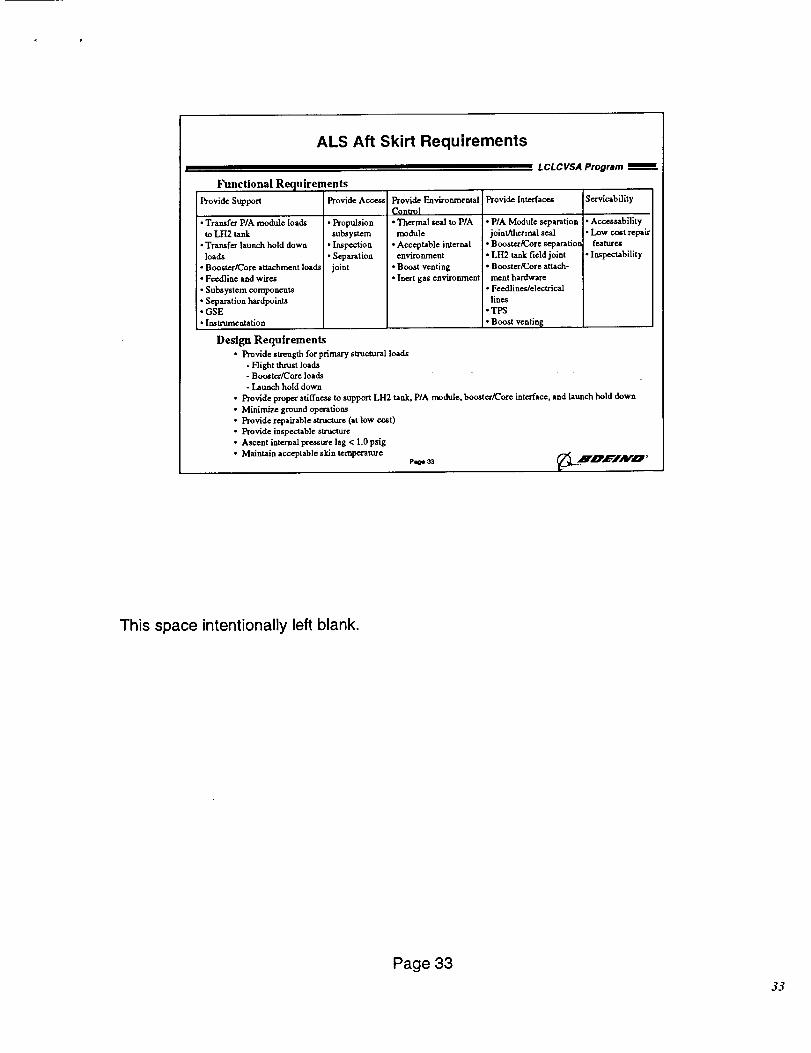
ALS Aft Skirt Requirements
Functional Requirements
LCLCVSA Program
Provide Support
• Transfer PIA module loads
to LH2 tank
• Transfer launch hold down
loads
• Booster/Core attachment loads
• Feodline and wires
• Subsystem components
• Separation hardpoint_• GSE
• Instrumentation
Provide Acce_
• Propulsion
subsystem
• Inspection
• Separation
joint
Design Requirements
• Provide strength for primary structural loads
- Flight thrust loads
- Booster/Core loads
- Launch hold down
Provide Environmental
Contro]
• Thermal seal to P/A
mod_Lle
• Acceptable internal
environment
• Boost venting
• Inert gas environment
Provide Interfaces
• P/A Module separation
joint/thermal seal
• Booster/Core separation
• LH2 tank field joint• Booster/Core attach-
ment hardware
• Feedliaes/electrical
lines
• TPS
• Boost ventin_
Servicability
• Accessability
• Low cost repair
features
• lnspectability
• Provide proper stiffness to support LH2 tank, P/A module, booster/core interface, and hunch hold down
• Minimize ground operations
• Provide repairable structure (at low cost)
• Provide inspectable structure
• Ascent internal pressure lag < 1 0psig
• Maintain acceptable skin temperature Pao*_ _"X ..'B 'O'/'JAI/'_'
This space intentionally left blank.
Page 33
33
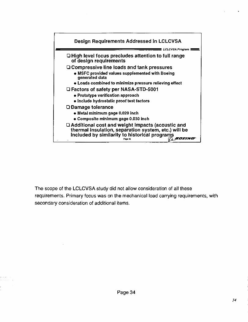
Design Requirements Addressed in LCLCVSA
LCLCVSA Program
O High level focus precludes attention to full rangeof design requirements
O Compressive line loads and tank pressures
• MSFC provided values supplemented with Boeinggenerated data
• Loads combined to minimize pressure relieving effect
O Factors of safety per NASA-STD-5001
• Prototype verification approach• Include hydrostatic proof test factors
O Damage tolerance
• Metal minimum gage 0.020 inch
• Composite minimum gage 0.030 inch
[] Additional cost and weight impacts (acoustic andthermal insulation, separation system, etc.) will beincluded by similarity tohistorical programs _ I
The scope of the LCLCVSA study did not allow consideration of all these
requirements. Primary focus was on the mechanical load carrying requirements, with
secondary consideration of additional items.
Page 34
34
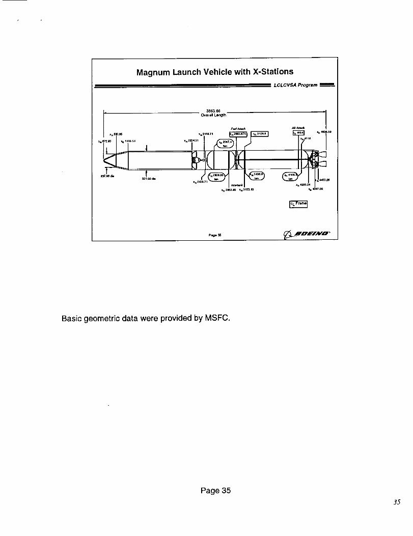
Magnum Launch Vehicle with X-Stations
LCLCVSA Program _=
3863.66 -i
Overall Length
Fmct Aa=¢/_ A1.4_
z n IIO._
Xnl _.5!
• ',M d_
=n241P_Tt
"n 2204"51 _
Xn2 I
Xn 2152.10 =n012o, I$
Paag* 3_ _...!D, FI.,VO"
Basic geometric data were provided by MSFC.
Page 35
35
Fairing Acoustic Environments
L CL C VSA Program
Vehicle
Titan IV
Jarvis
Sea Launch
ALS
Shuttle (STS-4)
External Overall
Sound Pressure Level
at Fairing
152.5 db
152 db
154 db
151 db
153 db
I Sea Launch acoustic treatment weights representative I
Page 38_,_ ,R,d_L"JAI/" O '
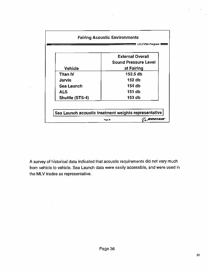
A survey of historical data indicated that acoustic requirements did not vary much
from vehicle to vehicle. Sea Launch data were easily accessible, and were used in
the MLV trades as representative.
Page 36
36
Thermal Environment Comparison
LCLCVSA Program
eoo_ / "''-.-..
+ ]/
i Y 7-'--_-•J / ..../' ..
o0oE.oo s OOE.Ol i coE.o_ i so[.o2 2 oo_.o2 2 so_.o2
0 Magnum and Sea
Launch trajectories
applied to Sea
Launch geometry
0 12 Inch nose
radius assumed
0 Temperatures for
no Insulation
0 Peak heating rates
• SL: 7.5
• MLV: 4.1
I Sea Launch TPS weights conservative_._,o,E,r, vo,Page 37
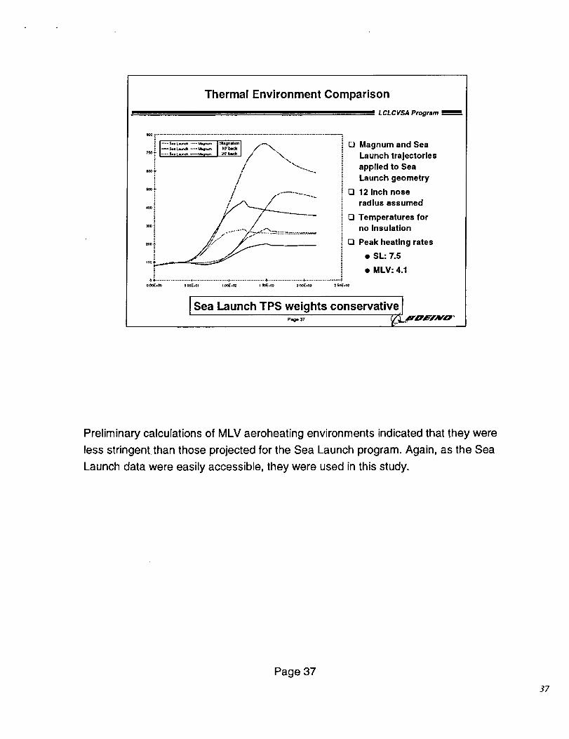
Preliminary calculations of MLV aeroheating environments indicated that they were
less stringent than those projected for the Sea Launch program. Again, as the Sea
Launch data were easily accessible, they were used in this study.
Page 37
37
Preliminary MLV Loads
Shear Load_F .....................................................
-!......._S_Axial Load
2) _--_ -/ ............
p=_o 38
LCL CVSA Program
Bending Moment
"} /i-" i
! "! j... !='i'" ""-. L,'"_._
.!......._,__J_... .........Compressive Line Load
l'-! -'%._ / .__1
•m'_......._UtI_____J_ ......!
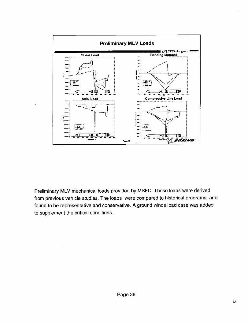
Preliminary MLV mechanical loads provided by MSFC. These loads were derived
from previous vehicle studies. The loads were compared to historical programs, and
found to be representative and conservative. A ground winds load case was added
to supplement the critical conditions.
Page 38
38
LOX Tank Line Loads
L CL C VSA Program
14000_Note:: SITs sk n thickness bued on the worst ...........................................................
s=lng condition: I12000_ * for proof condition sizing, use rain. of Fry or
Ftu/!.& (e room temp) Ii I" for ultimate loading, uoe material propsrtles I _ I /
.-,oo, ..... /
! -i I .fl p:;_..
i _ .... ::_:_...............Tm_km _
_Ullmale Io ixemmre
; _Ul_ale Wind=,unAJeledn 2_ ,x
24_0 2500 2600 2700 2800 2900 8
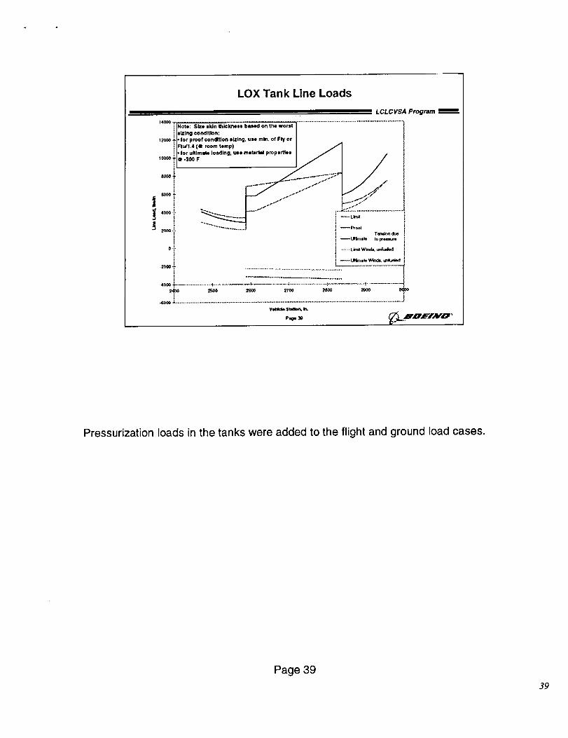
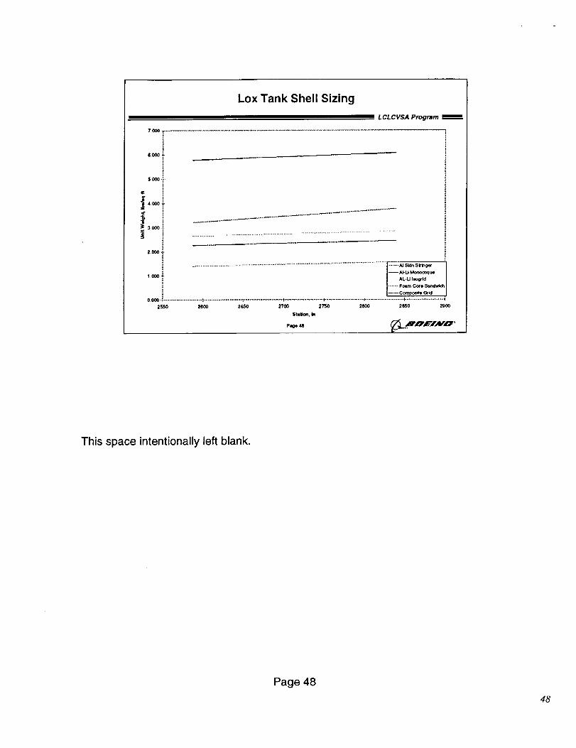
Pressurization loads in the tanks were added to the flight and ground load cases.
Page 39
39
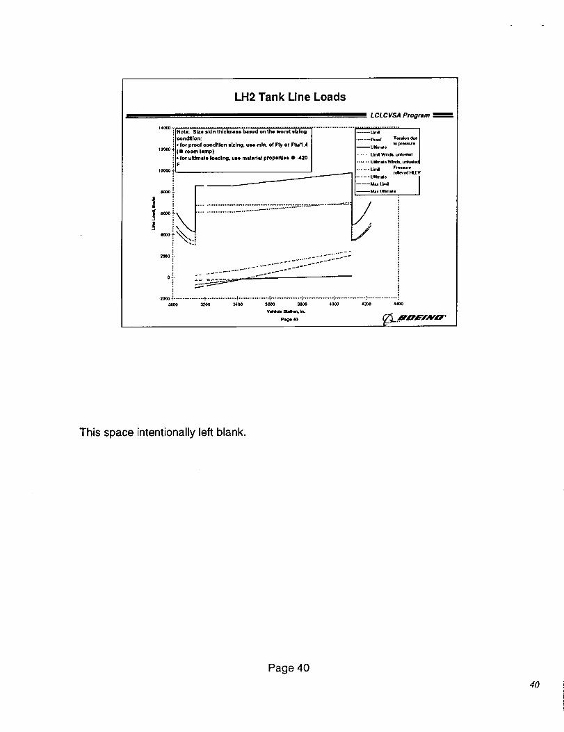
LH2 Tank Line Loads
L CL C VSA Program
14000 _ .......................................................Note: Size skin thickness bleed on the worst |lzlng -_Lkni l
....... PI'_r Temto_ dueoondKIon:
il" f°r Pr°°f c°ndltl°n sIzIng, une mln" °f Fry °r Ftu/l'4 Ultimde Io p(e=s_e
120¢0:l_e_n, roomtemp) ..... LlmtlW_d_.urduded
i t" for uhlmete loading, use msteds! properties • .420 Unknae Wind=, unlud
I_ellure:n relieved HLLV
.... UmmJeI
........ Max Limtl |
I
_,_, ,
_o i "2 _22-=-_22_:::::S::
.................._.................,.................,................._.................,.................._..................3000 0_00 3400 _3600 3800 4000 4200 4400
Yehlckm Hm, b_
Page 4O
This space intentionally left blank.
Page 40
40
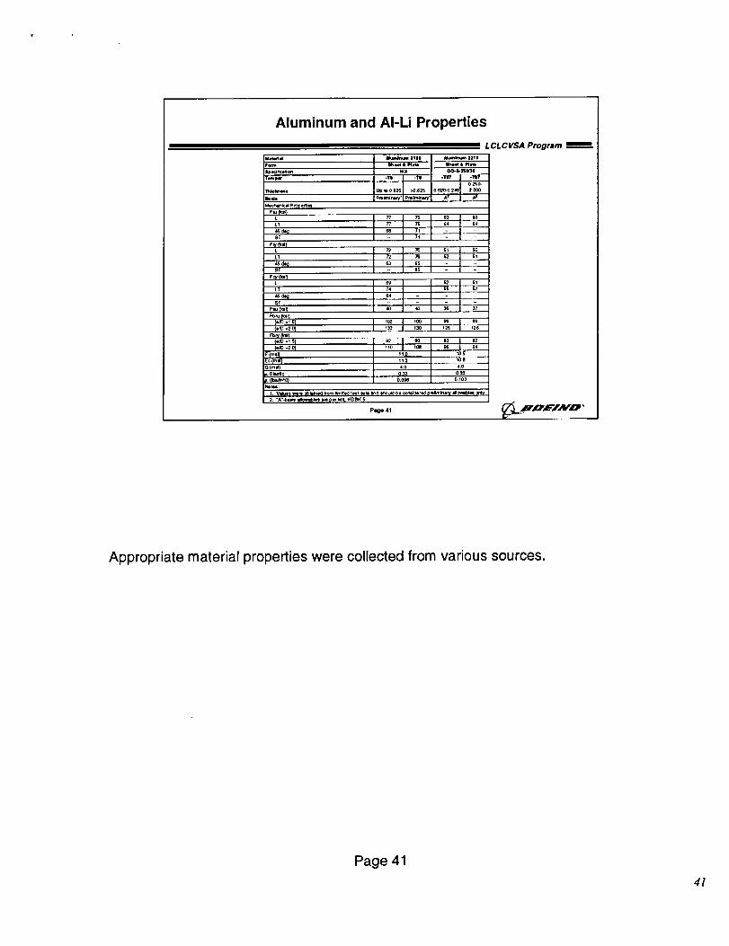
Aluminum and AI-Li Properties
aaumd
r_
|pedf_e_.n
F__,""c' I_t"_" _"°_1_l _-L 72 7O 5_
L'r ,, 72 70 52 Sl
= LCLCVSA Program _-
,lJumlft_im1111 Mcs_lrv4m 1ZII
WA O0-k24W_
1F_lmlC_Pq' F'_ir_rmty J
-TI -TO
U_ Io 0_5 >0._2S 0 o_o-o 34# 2 000
A I A=
L E_s_o ....
LT _ S2g_, _
Flu iks q ' _7
(*_ .20} 130 130 _2_ i25
(,rid -20) _0 tOe _ 94
E(mm_ _ 0 _ S
,? ,oo,4O
0.C4_ 0_0_
2 "A'-b==_ =rewle_* m pwMIL440_K-§
P_ge 41 _. ,HnEIAV'O '
Appropriate material properties were collected from various sources.
Page 41
4/
1,4
1.3 "_
! 1.1_-
}'Ti
_,o.e .!
0.7'i0.6 _
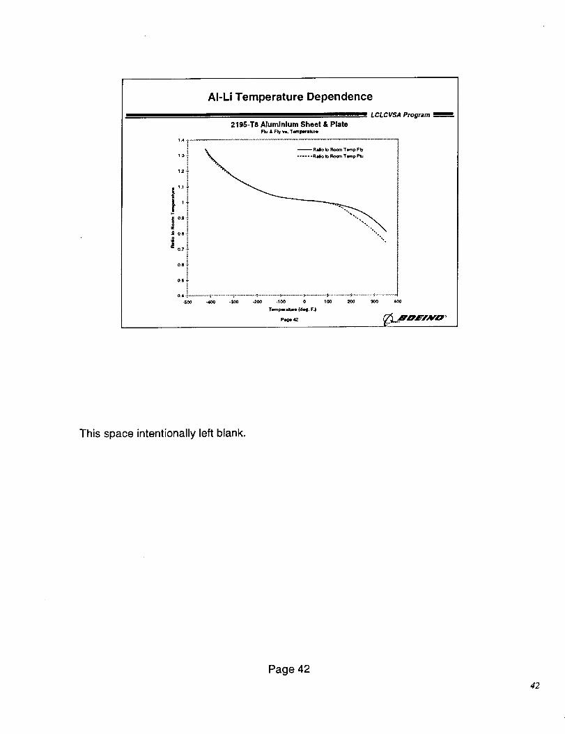
AI-Li Temperature Dependence
L CL C VSA Program
219S-T8 Aluminium Sheet & PlateFtu & Fry w, Tempecatum
.-'_.. Ra§o to Room Twnp F_
0,5/_
0.4 _ ..... : ........... : ............ ",............ _=.......... P ....... P........... ";"........... "P.......
-S00 -400 -300 -200 -100 0 100 200 _ 400
Teml_ a_um (deg. F.)
This space intentionally left blank.
Page 42
42
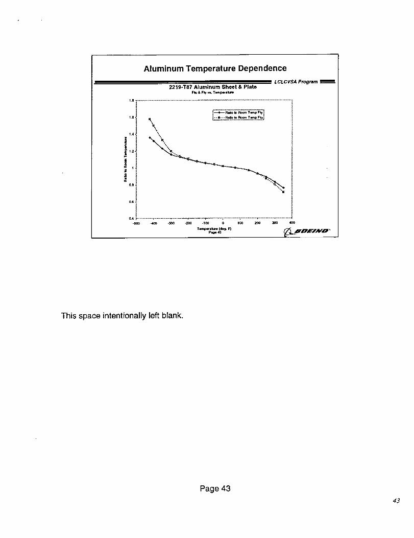
Aluminum Temperature Dependence
L CLCVSA Program2219-T87 Aluminum Sheet & Plate
Ftu • Fry re, T,_",p_ature
1.8 ....................................................................................................................... z
1.6,
1.4,
J
12,
|OC $.
O_B.
0.6'
0.4 ¸
-500
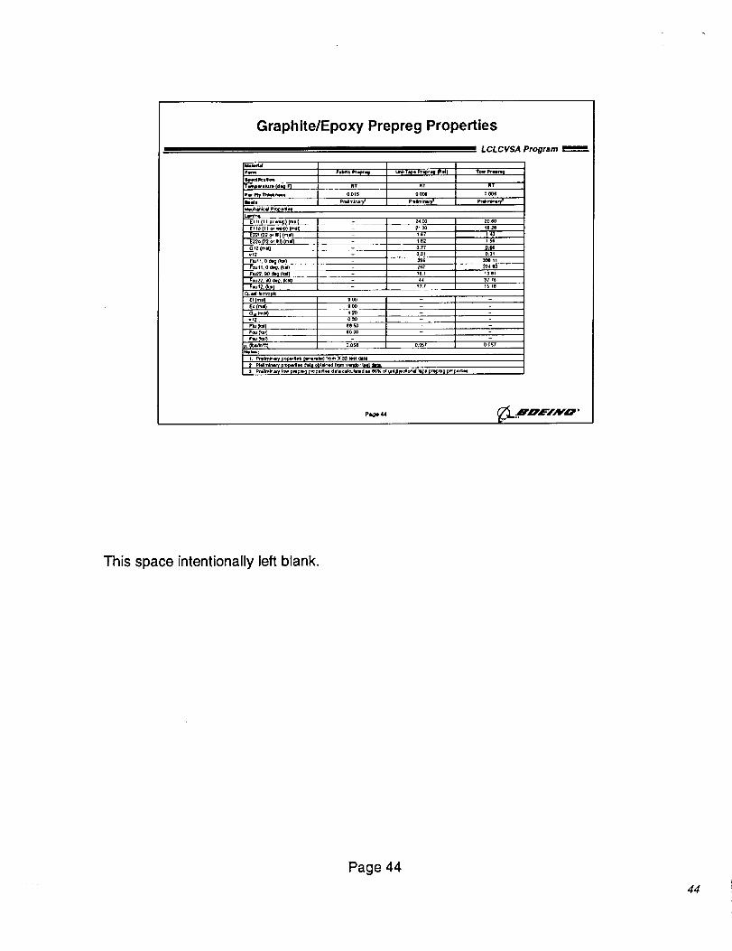
Graphite/Epoxy Prepreg Properties
LCLCVSA Program =m=_m
U _dd
Fn Fo_® pr.f..f U,_-T._ P"i* '_ _'*) T_ _,,_r_
¥_pwoluto (V_ F)
P_ I_lr l_hmc_n==m
Llmln4z
_I !t(i| Or tw_l _ml)
E II_ (IIm' _,m_m_) (mmr_
_"_ (22 o_ mml)(m_
RT RT RT
I OOq5 O(x_ 000(
2400 20GO
2130 le2e
1(1 140
le2 1_
0 77 06,$
031 031
Flul I,0 _ (_Q L- _
rcu i_ L _2
900
900
120
ee,'_
eo_
Fmui2. O_W)
Qu=m_ _ot_ L:x_¢
£((mmQ
Eo(mw)
Omm_¢)
vii)
pm _
224_3
161 13OI
74 3 7 7_i 7 iS le
0 O$8 0_7 00S7
pag_ 4,i
This space intentionally left blank.
Page 44
44
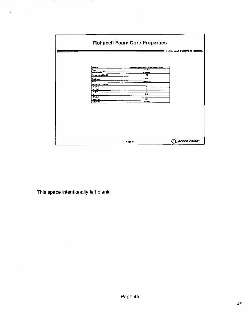
Rohacell Foam Core Properties
L CL C VSA Program
B wd_
F_
m_cw_l
Et_,)Eop=_
F_ Ip_Q
Ploh41¢44 (Is4 ly_ e_cr_lm M e} RI _i 41 F4_
I|OWF
nvMcd
lit
N/A
p_lmk, aq
2o
2O
7
0 003ge
Page 45 _L.HOEIAV',G' '
This space intentionally left blank.
Page 45
45
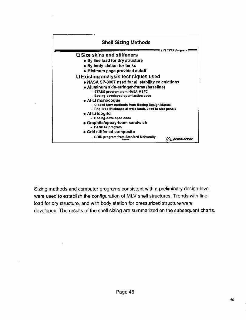
Shell Sizing Methods
LCLCVSA Program m
Size skins and stiffeners
• By line load for dry structure• By body station for tanks• Minimum gage provided cutoff
D Existing analysis techniques used• NASA SP-8007 used for all stability calculations• Aluminum skin-stringer-frame (baseline)
- STASS program from NASA-MSFC
- Boeing-developed opUmizaUon code
• AI-Li monocoque- Closed form methods from Boeing Design Manual
- Required thickness at weld lands used to size panels
• AI-Li isogrid- Boeing-developed code
• Graphite/epoxy-foam sandwich- PANDA2 program
• Grid stiffened composite- GRID program from Stanford University
Page 46
Sizing methods and computer programs consistent with a preliminary design level
were used to establish the configuration of MLV shell structures. Trends with line
load for dry structure, and with body station for pressurized structure were
developed. The results of the shell sizing are summarized on the subsequent charts.
Page 46
45
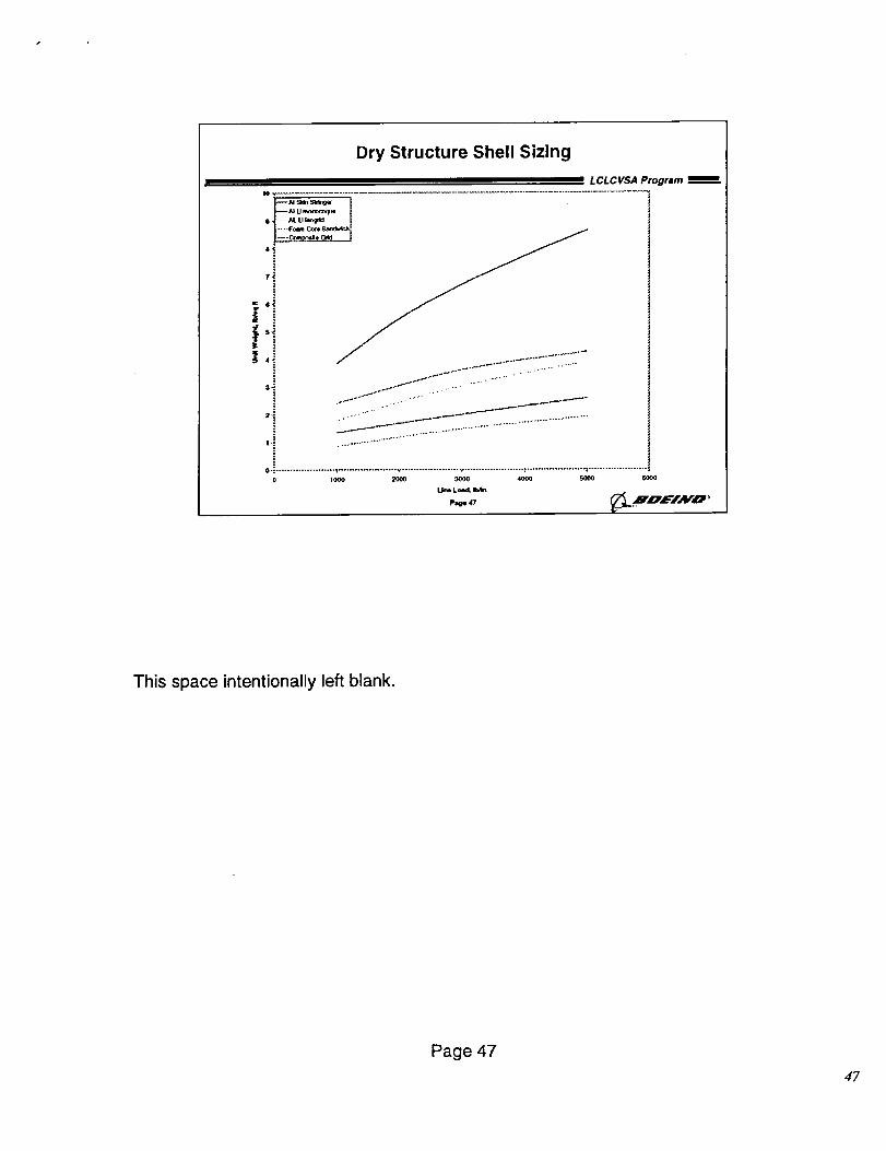
Dry Structure Shell Sizing
= LCLCVSA Program
_AI 5Mn Std_gw 1
'iTi
6t
St
4t
lJ-l,
'i1.1
o ....................... I ..................... v .................... _ ..................... ¢ ..................... : .....................
0 1000 2000 3(x)o 4000 5_00 6000
u_ Levi,
p,_ ,7 _L.'H 'O'¢='/AF_ '
This space intentionally left blank.
Page 47
47
7.000 _-
!i
e.000
Lox Tank Shell Sizing
I LCLCVSA Program mmm
$.00o ...
_ 4ooo $
2ooo*"
1.000
................................................................................................................ .;.;LId S_n s_
-- A_ U Monoooqul
AL-U h_lrld
...... Fo_n Coco _mdwich
-- Com_eite Grid
2550 2600 2650 2700 2750 2800 2850 2900
StaUq:et, Im
This space intentionally left blank.
Page 48
48
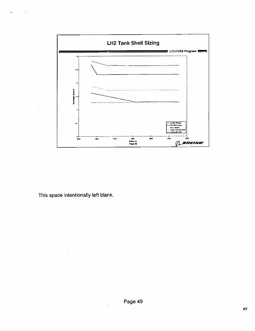
LH2 Tank Shell Sizing
LCL C VSA Program
=i
ilS_-
i
This space intentionally left blank.
Page 49
49
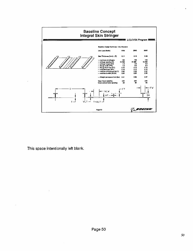
Baseline ConceptIntegral Skin Stringer
L CL CVSA Program
Bas_ine De#,_n Summ aay - Dry StnJclure
Line Load (n:_n) 1000 3000 5OO0
_,dn Trackless (_ch). (3") O. 11 O.10
-- numl:_m of Itr_gers 100 100
-- stdn_ q:,c_g ($) 10.3_ 10.399
-- strin gel height (SH) 1.5 3.0
-- lanp widm (FW) t.$ 3.0
-- |ange qhid_neu (FT) O. t5 O. 12
--w_b i'_nees (WT) O. t5 0.12
-- wdd brad INclmeN (WLT) 0.(_ 0.02
-- wdd _*'idqh (WLW) 2.00 2.00
-- We_t per IKlUare too({1_) 2.41 3.(_
Mawr hme e.p_lno 2,40 240
Inte_nedato frame q_acing 48 eO
0.20
10o
10.399
3.0
3.0
0.12
o.12
o.o2
2.00
4.27
24O
60
P_
This space intentionally left blank.
Page 50
50
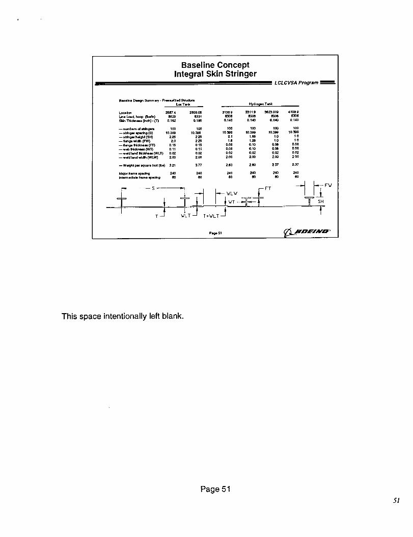
Baseline Concept
Integral Skin StringerL CL C VSA Program
I_=el_e _ _lmm ary - Pr(mlmJdzed Stmc-kNre
LOKTank
Localon 2587.4
L_* L_d, hoop Ob_) 6829
Skin Thldmm (_¢lh) - (T) 0.152
-- hum benl ol sb(ngees 100
-- =t_g_ _dng (S) 10.300
-- stinger h_ght (SH} 2,25
-- Ilange wtd_ (FW) 2,0
-- Ilange Ihldme=l (F'r} 0,15
-- wlb iNd_mmt (WT) 0.11
-- wdd I_d _¢kne_ (WLT) 0,02
-- weld lend _d_ 0NLW} 2, 00
-- Weight per equate foot (Ibs) 3.21
Msjor Irame I_ 240
_te_m o4ab _-ne =pacing 60
,J
H_clro_en Tank
2839.05 3136.0 3311.9 3623,0198331 6306 _ 8308
0,1_ 0,140 0.140 0.140
100 100 100 100
t0,009 10,309 10.300 10_00
2.25 2.t I.e6 1.0
2,25 I.e 1,25 1.0
0,15 0.00 0.10 0.06
0,Sl 0.08 0,10 0.08
0._ 0.02 0.02 0._
2,00 2.00 ZOO 2.OO
3,77 2.63 2.(_0 237
240 240 240 240
e0 60 60 _0
H I£T
4108+9
0.140
IOO
10.3_1.0
1.0
0.08
0,08
0.02
2`00
2.37
240
6O
Page 51 _._X,O'E/AFO"
This space intentionally left blank.
Page 51
5!
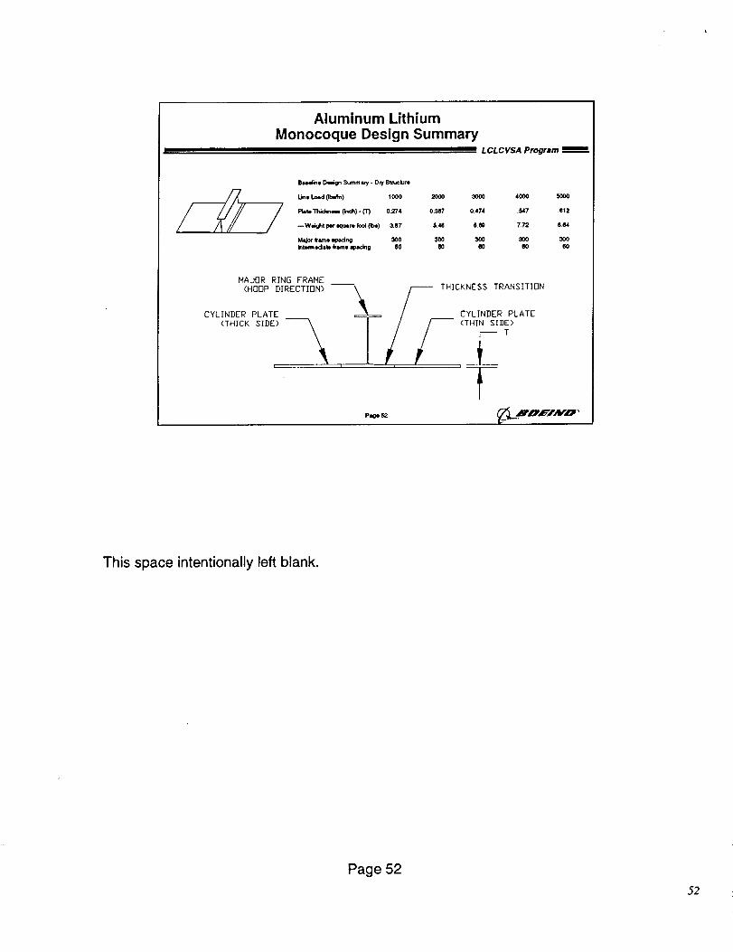
Aluminum LithiumMonocoque Design Summary
L CL C VSA Program
B_,eline De=I_I Sumrnmy. Dry Stmclute
Line Lmid 0_) 1000 2000 3000 4000 5000
Rate Thidm+m, _n_h) - iT) 0.274 0.387 0.474 .547 .e12
-- We;ght per =qua re _o((lb=) _87 5,4(I 6.8G 7.72 8+64
Major frame _ :300 300 300 _ 300
In_oclab f_smo macing 60 IIO O0 60 60
MAJBR RING FRAME
(HOOP DIRECTION) ---_ / THICKNESS TRANSITION
CYLINDER PLATE _ / CYLINDER PLATE
<T.ICK_IDD_ _ / / -- <THINSIDe,
\ 1//J _ i , --
This space intentionally left blank.
Page 52
52
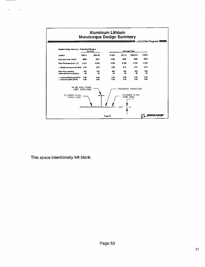
Aluminum Lithium
Monocoque Design SummaryL CL C VSA Program
Buelkle Deeign _ummllry - Primludzed Stmciu(e
Lox Tank Hydrogen Ta_k
Locdon 2587.4 2839.Q6 3136.9 33tl.9 3623.019 4108.9
Line load. hoop (1beAn) 6829 8331 _ (f306 _06 6306
Plate "r_icl_et4 Cinch). (T) 0.4t0 0.430 0.190 0.164 0.164 0.164
--W_l per square foot (Ibs) 5.79 0.07 2.68 2.31 2.31 2.31
Major kame Ipeck_ 300 300 300 300 300 300
I_tecmqK:lab flame ipldng eO 00 60 eO eO 60
-- w_d la_d _l_ck_e_ {W LT) 0.02 0,02 0.02 0.02 0,02 0,02
-- weld la_d widl_ C_/LW_ 2.00 2.00 2.00 2.00 ZOO 2,00
MAJOR RING FRAME
(HOOP DIRECTIDN) _ S THICKNESS TRANSITION
CYLINDER PLATE _ / CYLINDER PLATE
(THICK SIDE) --_ TI._/__F__T/ /--- <THIN SIDE)
FP,_ s3 _..B',O'_':'/NO'"
This space intentionally left blank.
Page 53
53
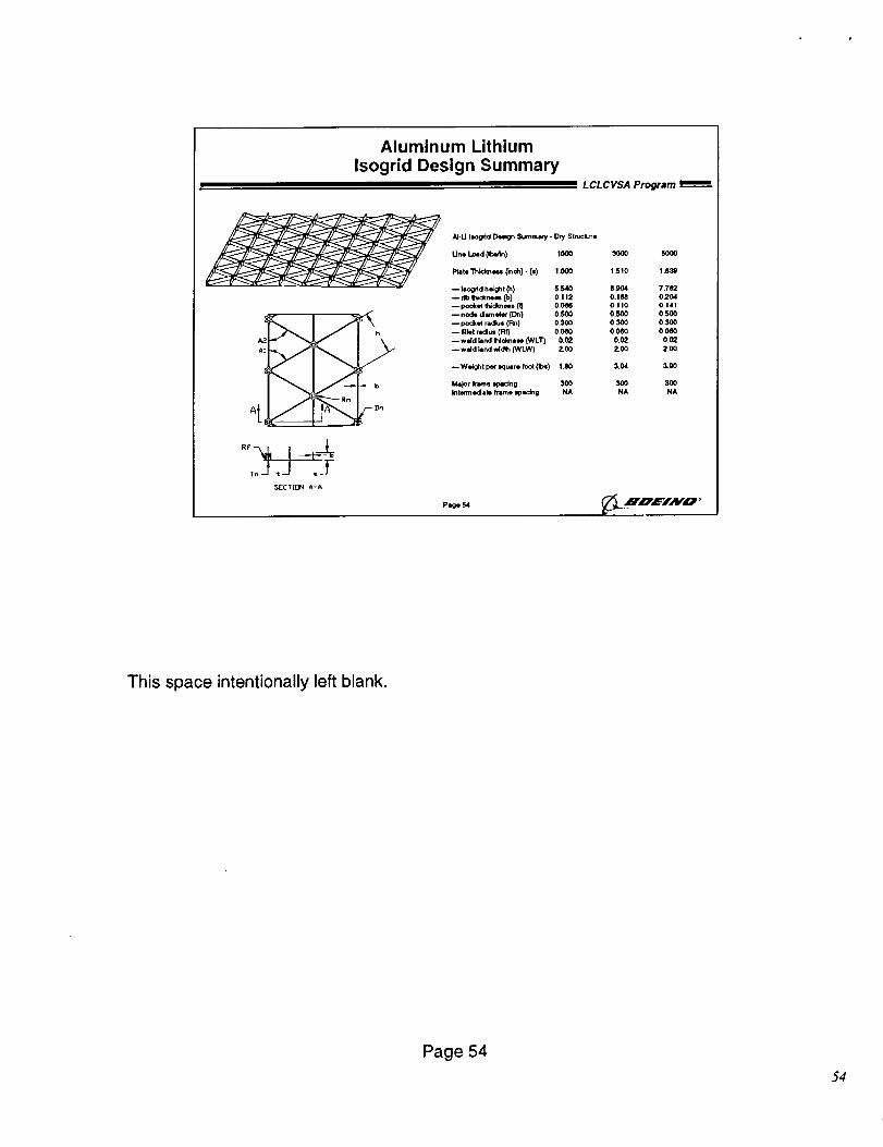
Aluminum Lithium
Isogrid Design Summary
A!
"-b
A - Dn
,oJ,J,fSECT_ A-A
N-U lJogrid Design Sumrn_ry - D,y St*_,ctJr=
LCLCVSA Program _-
Pl_e 54
Une Load (Ib_n) 1000 3000 5000
Plate Th_,_n _ (_ch} - (=) 1.000 1.510 1.83g
-- l_d h_ght (h) 5.540 8,_4 7.7e2
-- n_, _dkr, iN= (b) 0.112 0.188 0204--pocket Itddlmes= (_ 0.0t_ 0.110 0.141
--node d a"_ ,a_ (D_) 0,500 0.500 0.500
--pocket radius (Fin) 0.300 0.3(XI 0.300
-- Met radius (Rf) O.OeO 0 . O_ 01_
-- wdd land _clmow (WLT) 0.02 0.02 0.0_
-- weld hind wldlh ONLW) 2.00 2.00 ZOO
--Weight pe¢ lquare lOOt (Ib=) t,_ 3.04 3.gO
kqdor hme _=dng 300 300 300
Intern1 edlab fre.me Iplclng NA NA NA
• "" ,,, J
This space intentionally left blank.
Page 54
54
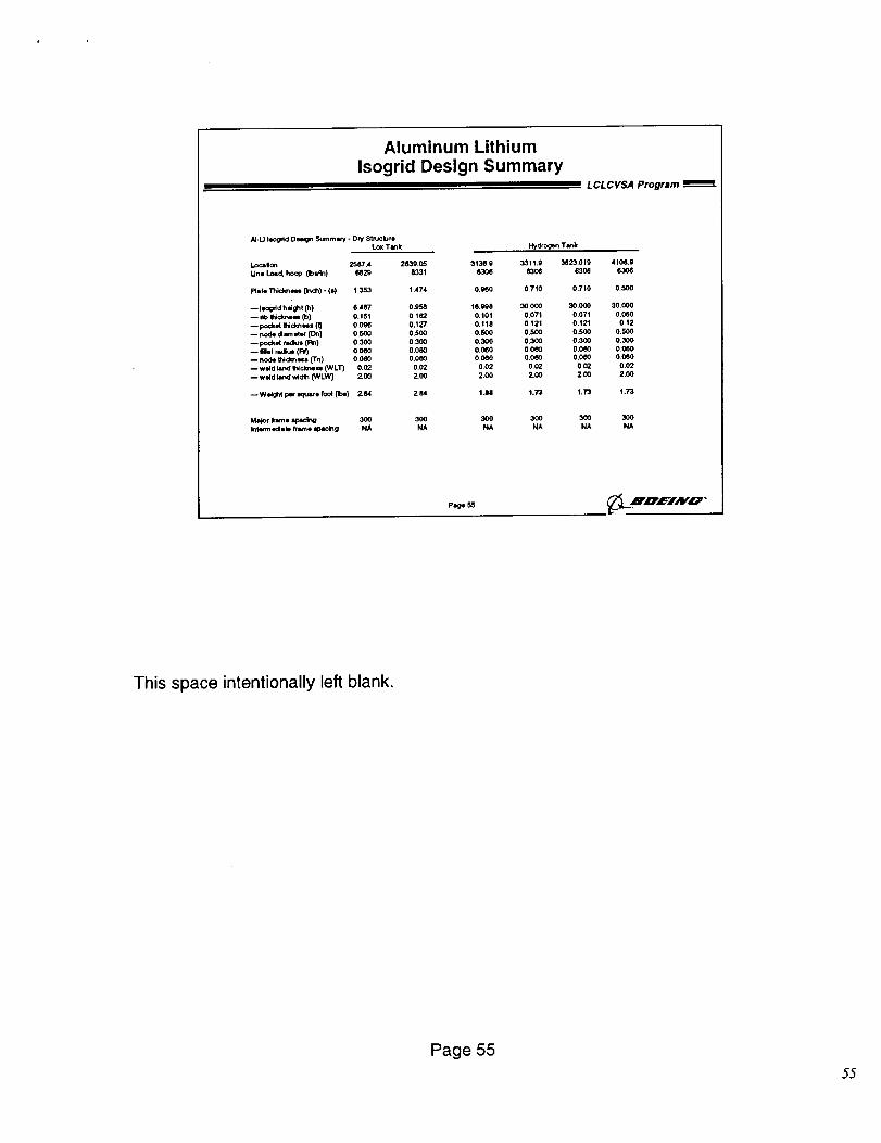
Aluminum Lithium
Isogrid Design SummaryL CL C VSA Program
N-u Isogdd Deign Summery - Dry $truclureLc_ Tmnk
I.oc=lon 2587.4 2839.05
Unl Load. hoop Obi4n) eS_ 8331
Plate Thid_, (itch) - (s) 1.353 1,474
-- Ilogdd h_ght (11) 0.487 0.95_
-- db q_cknesl (b) 0.151 0.i62
pocket t'ltdlmes= (_ 0.096 0.i27
-- node d_ eta" (On) 0,500 0,500
-- pocket radius (I_) 0.300 0.300
-- Met radius (Rt) 0_060 0.0OO-- node INckn m (Tn) 0,060 0.0OO
-- wdd land ffCcknem (WLT) 0,02 0.02
-- wdd land widlh (WLW] Z OO ZOO
-- We_ht per Klu_re foot fibs) 2.64 2.84
Major hm• =¢_lr_ 300 300Inte_ edisll trame =pacing NA NA
, ,, F_,drogen Tank
313A9 3311.9 3t523.010 41GB, g
S306 e306 6308 6306
0.000 0.710 0.710 0.500
16,998 OO.000 30.000 30.000
0.101 0.071 0,071 0.060
0.118 0,121 0J21 0,12
0,S00 0.500 0.500 0.500
0.300 0.3OO 0.300 0.300
0,0_0 0.060 0.0_ 0_060
O.0eO 0.060 O.OeO 0_060
0.02 0,02 002 0.02
2.0O 2.OO 2.00 2,00
! .U 1.73 1.73 1.73
300 300 300 300
NA NA NA NA
P6ge 56 _LHO:c='1.,vo '
This space intentionally left blank.
Page 55
55
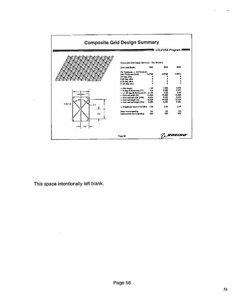
Composite Grid Design Summary
LCLCVSA Program
Compodte Grid D_ign Summary - Dry _-t_-_ute
Une Load Libel) 1000
l_y'Thiclu'_N = O.01140nch)Skln TNdm_= (;rich) 0,0798 0.07_
# 0 deg_ _ 0 0
# 9o de_ pl_ 3 3
# 20 deg. ples 2 2
# -20 d_. pies 2 2
-- Rb Height t .25 1.825
-- 0 d_ db _dce_ (TT) 02 0.325
-- _. 40 dig do t.ido_ (T) 0.175 0.25
-- Unit col wid_ (W) 13.866 13.8(_
-- Unit cd Iv_N*idlh (HW} 6.933 e.933
-- Unit cell height (H} 16_28 18,52e
-- Unit eel half helght 04H) 8263 8263
-- Weight per iquare foot (Ib$) t.36 2_00
Ma_or _ame lp&dng NA NA
Int4m'_e(:l =b frame =p_rt g 330 330
,t/ .II_ _..I
(_ . //11 I
300O SO00
Page 56
0.0_12
0
4
2
2
! .875
0.377
0.30
13.866
8.933
18.526
8263
Z58
HA
33O
.U,_,F/AFO '
This space intentionally left blank.
Page 5656
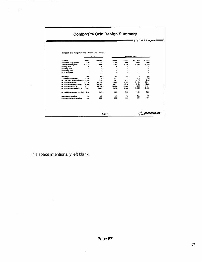
Composite Grid Design Summary
LCLCVSA Program
Compolitl Grid De_ _ummaly * prel=urized $tmclure
L_ Tank Hydro_m Tank
Loca i_'l 2587.4 2839,05 3136.9 3311,9 3e2301g 4108.9
U,n* I._d. hoop Ob_In) M29 8331 630(I 8306 B306 030_
SNn Thldc.eml 0n<h) 0.1482 0.15M 0.140 0.t40 0.140 0.140
# 0 deg. pile= 6 0 4 4 2 2
# 90 d_ Idle= 3 3 3 3 2 2
e _70 d=_ Idles 2 3 2 2 2 2
# -70 _ pies 2 3 2 2 2 2
Rib H_ght 1.5 1.5 1.0 1.0 1.0 1 0
-- 0 deg rib t_idkne_ {'t-r) 0325 0325 0.25 .175 .175 .175-- ,#- 40 d_g db Ihidmem (1") 0266 0.30 025 0.25 0.25 025
-- U_t cell wid_ ON) 25.136 25,136 31.0(I 31.06 31.08 31,0_
-- UrJt c*ll heX wid_ (HW) 12568 12568 15_53 15.53 15.53 t0,¢3
-- Unit oell h_ght (H) 11.722 11.722 11.304 11.304 11.304 11.304
-- U;dt _ Ma _ _ 5.861 5.561 5.e62 5.652 5.6,,_2 .5_62
-- Welght pe¢ Wluare foot 0bs) 2.26 2,45 1.63 1.29 1.29 129
Ma_ot Irene r,pt_ng NA NA NA NA NA NA
lnt*wnedlate frlm.e macing 330 330 330 330 330 330
pig* S7 _L ..mnE/HO '
This space intentionally left blank.
Page 57
5?
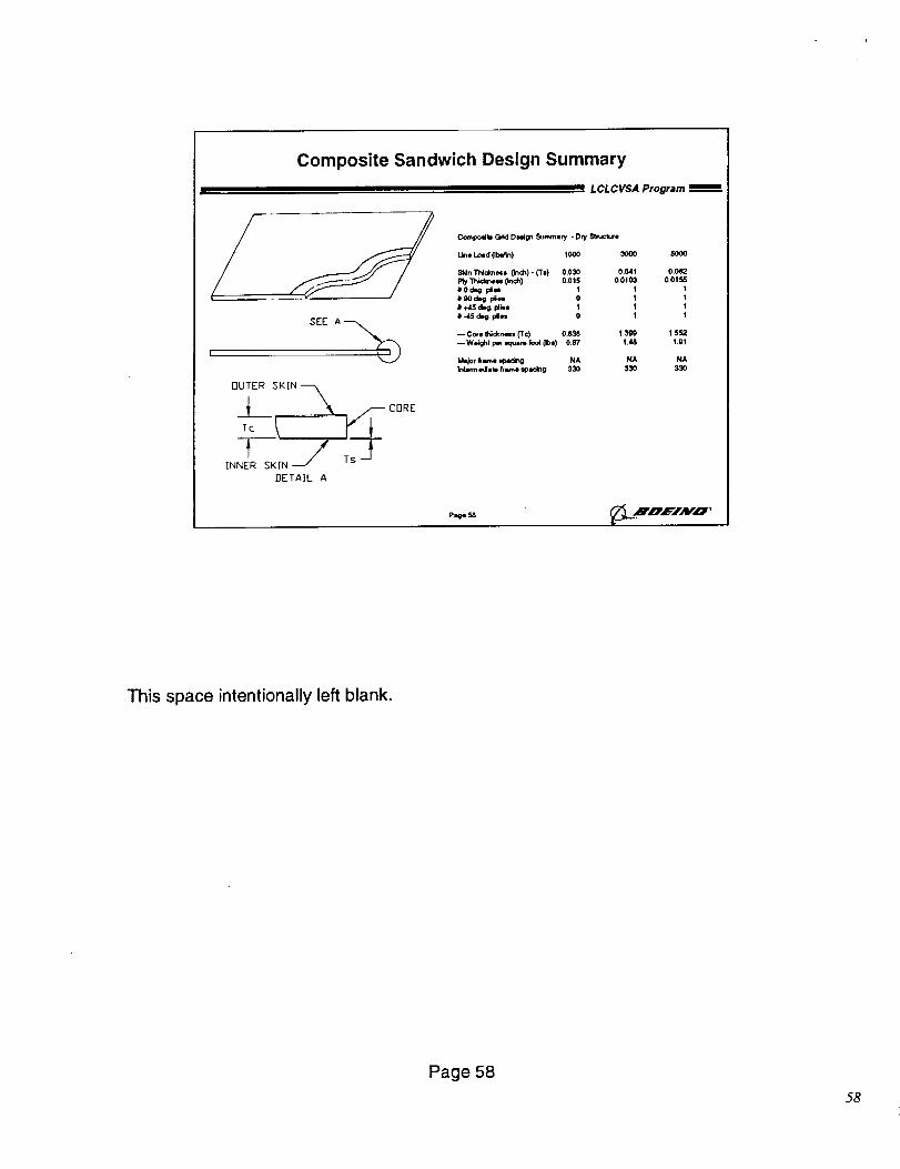
Composite Sandwich Design Summary
LCLCVSA Program Bin=
/
OUTER _;KTN -_
_____ _ _ _CORE
DETAIL A
Cornpo=fbG_I Dod_ £_mm=ry - D_f StnJcture
line Load(lb_n) 1000 3000 5000
SkinThldme== ('inch)- (To) 0.030 0.041 0.0(12P_ Thld_u, (Inch) 0.015 O.Ot03 0.01_# 0 deg. l_lN 1 1 1# 90 d_ idle= 0 1 !e +45 d_ plie= 1 t I• -45 deg_Idle= 0 t 1
Core INd(r,_= ('rc) 0.838 1.399 1.552--Wei_t per _l,,:.mrefoot(Ib=) 0.87 1.48 1.91
Ida,jofhrne q_idng NA NA NAIntermedisb h_e spa,dng 330 330 330
P=ge 58 _L.HpEIMo •
This space intentionally left blank.
Page 58
58
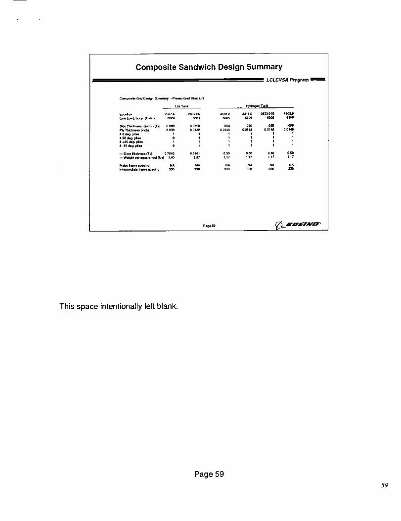
Composite Sandwich Design Summary
LCLCVSA Program
COml_lib Grid Deign Summary - prewudzed StnJcture
Lox Tank H_,dto_n Tenk
I._¢alon 2587.4 2839.05 3136.9 3311.9 3823019 4108.9
L_* Load, ho_ 0b_n) 6829 11331 (1306 (t30_ 83015 830e
Skin l_dm_,= (_0h) - (T=) 0.Oe0 0.072, .(_9 .0,_ .0r_ .069
ply Thick_ Onch) 0,030 00182 0,0148 0+0148 0.0148 0,014&
# 0 deg. pile* I 1 1 1 I 1
II gO dl,g. Idlell 0 I 1 t I 1
tll _15 dJ_ tol_s I 1 1 1 I I
# -45 de_ ph= 0 1 1 t I 1
-- Core INcknes= (Tc) 0.7043 0+6161 0,50 0.50 0.5_ 0.50
-- Weight W =qu_re (oot {Ib=) 1.40 t+b'7 1,17 t.17 1.17 1,17
M41_orkw'ne iq_dng NA NA NA NA NA NA
I_tem_ edall h_'ne =pacing 330 330 330 330 330 330
p=ge_
This space intentionally left blank.
Page 59
59
Weight Estimation Method
LCLCVSA Program _=
CI Vehicle and element weight estimates for baseline
design (including subsystems) generated using
parametric program calibrated to ET weight
O Boeing Weight Estimation Tool used to generate
vehicle weight estimates from unit weight values
for each concept
Q Vehicle inert weight trends for each concept
generated to support vehicle resizing
Pa_eeO __ Jn, C='IAWO '
The shell structure weight trends were rolled up to the total vehicle weight using
established preliminary design methods and computer programs.
Page 60
5o
Vehicle Resize Method
L CL C VSA Program
O Performance calculated using SPOT based onInert weight trending from weight estimate
O Vehicle GLOW adjusted to maintain constantperformance (payload to LEO)
• 27.5 ft diameter maintained (except monocoque)
• Monocoque diameter increased to 31.5 ft to prevent corenozzle exit planes from extending below SRBs
• Impact of shorter tanks (up to 20 ft with compositesandwich) on other concepts not addressed
- Nozzle exit planes
- SRB attachment
page@1 _ .XnEIAV'O '
Established preliminary design methods and computer programs were used to
assess the feedback of vehicle dry weights changes on propellant requirements, and
in turn, vehicle dry weight. In this calculation, vehicle performance and diameter
were kept constant, except for the monocoque concept, which could not be closed
within the 27.5 foot diameter constraint without extending the core engine nozzles
beyond the SRB exit plane. The monocoque core was allowed to grow to 31.5 feet
diameter to avoid this situation. Similarly, resizing lighter concepts would result in
core engine nozzle exits further above the SRB exit plane than the baseline concept.
Shortening of the tank module (up to 20 feet with the composite sandwich concept)
could also impact the SRB attachment scheme.
Page 61
6]
1600_0,
140000 t120000
|00000 •
$0000 o
(_,0000 -
4(X)O0 -
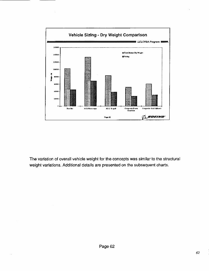
Vehicle Sizing - Dry Weight Comparison
ii ==l LCLCVSA Program
P_
The variation of overall vehicle weight for the concepts was similar to the structural
weight variations. Additional details are presented on the subsequent charts.
Page 62
52
o._4
o,s4
o.7.1
o6 I
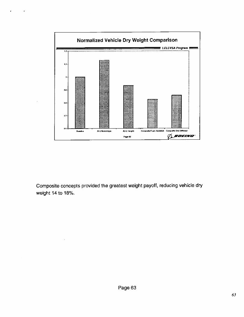
Normalized Vehicle Dry Weight Comparison
L CLC VSA Progrmm
Ba_ /U-U Mo_coq_ @..4.1
P_ _3
!:i:i$i:i:i:i$_:i:i
....................,IY;YTIC-YYl
_.:.:!_i_-;:j'_
::':':':':':"_:,-:::'.:i
,
_oam S_*d_ Compo_le _id Siifle_4
Composite concepts provided the greatest weight payoff, reducing vehicle dry
weight 14 to 18%.
Page 63
63
70,000
60,000
50,000
40,000
30,000
20,000
10.000
Vehicle Element Weight Comparison
L CLCVSA Program
[] Baseline
• AkLI Monocoque m
rt AL.LI Isogrld m
n Composlte/Foam Sandwich
• Composite Grid Stiffened I
|
Fwd LOXTank Intertank LH2Tank AflSkid Other FairingStructure
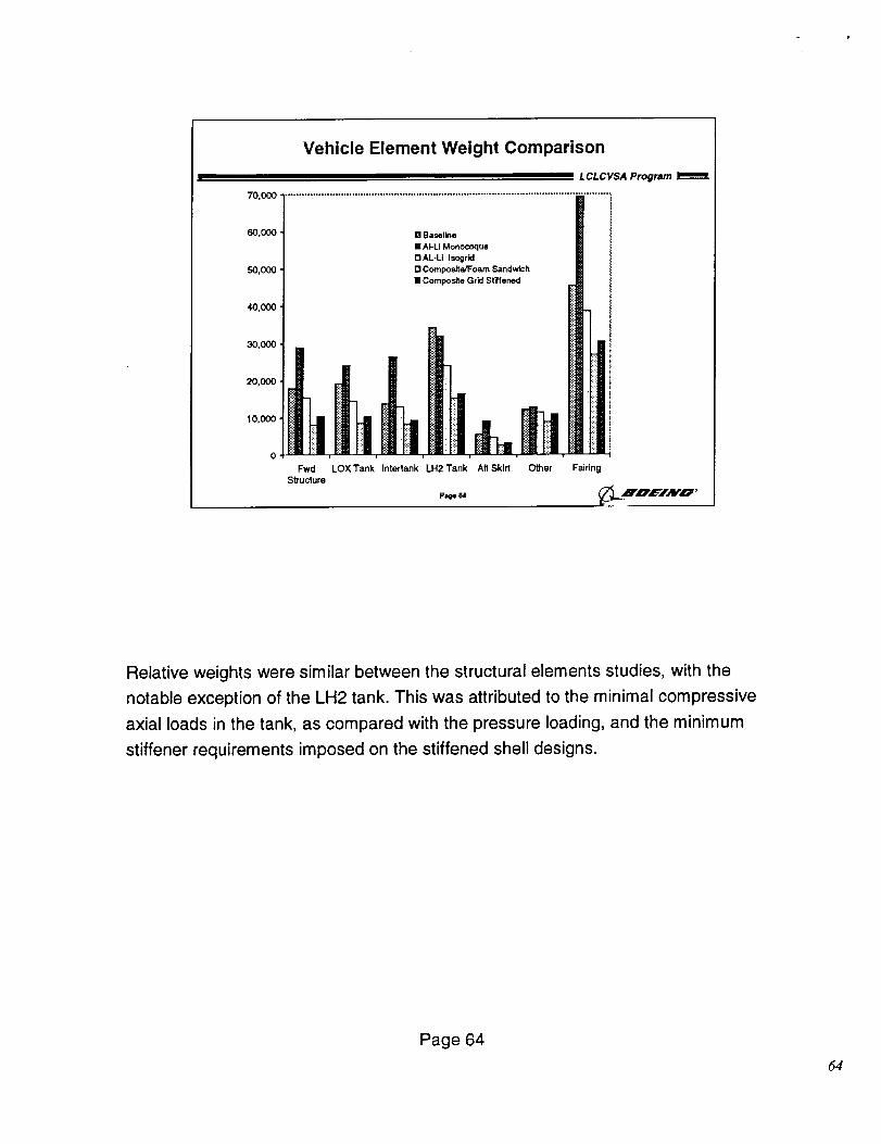
Relative weights were similar between the structural elements studies, with the
notable exception of the LH2 tank. This was attributed to the minimal compressive
axial loads in the tank, as compared with the pressure loading, and the minimum
stiffener requirements imposed on the stiffened shell designs.
Page 64
64
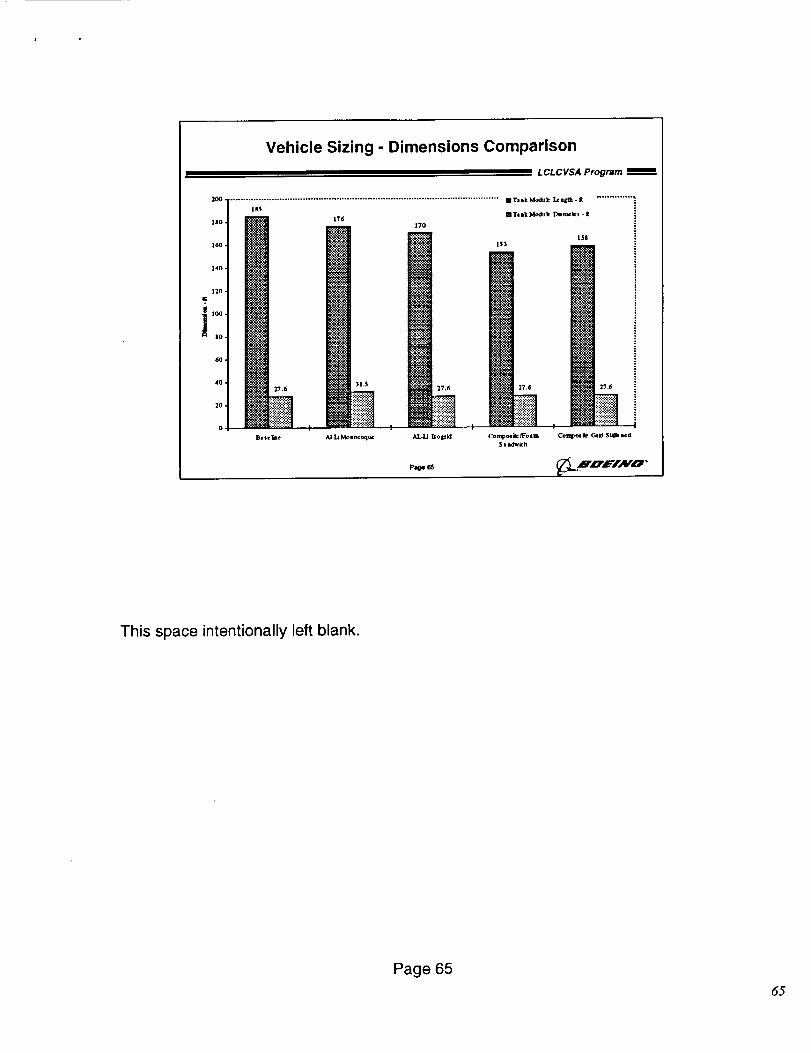
Vehicle Sizing - Dimensions Comparison
L CLCVSA Program
2oo_ ........................................................................................................ i T= akModlukI¢ =l_ - It .............. "
140 -I
120 4
i t004
ao 4
604
4o I
2o I
o!
lao4
Ba$cliBe
176170
153
AI-LiMonocoque A]r]IJ ]=o1_i4 Comlpo=ikefJFoamSaadwich
Pig+ O6
mTaakModuk DiJrotlcl -It
158
!
Com ,olllcGrid Sfi_mcd
This space intentionally left blank.
Page 65
65
6000000.
5000000 •
4000_00 •
8
,L _ooooo •
2000(_00
10000O0
Vehicle Sizing - GLOW Comparison
LCLCVSA Program mm
OPairmlr
IIpmyload
0 Ta lk Moduk Isert
I_op_klou M,odu L- bi¢rt
m_o_kut
m SRB _,AI
! I I I
]Balerlme AJ-T;)_oaocO(jlUe A,L-I.J ]_oB[14 Col_0,olk_Foulu CO_lpOlile Of_ St_c_dSaud_k_h
Pu_e
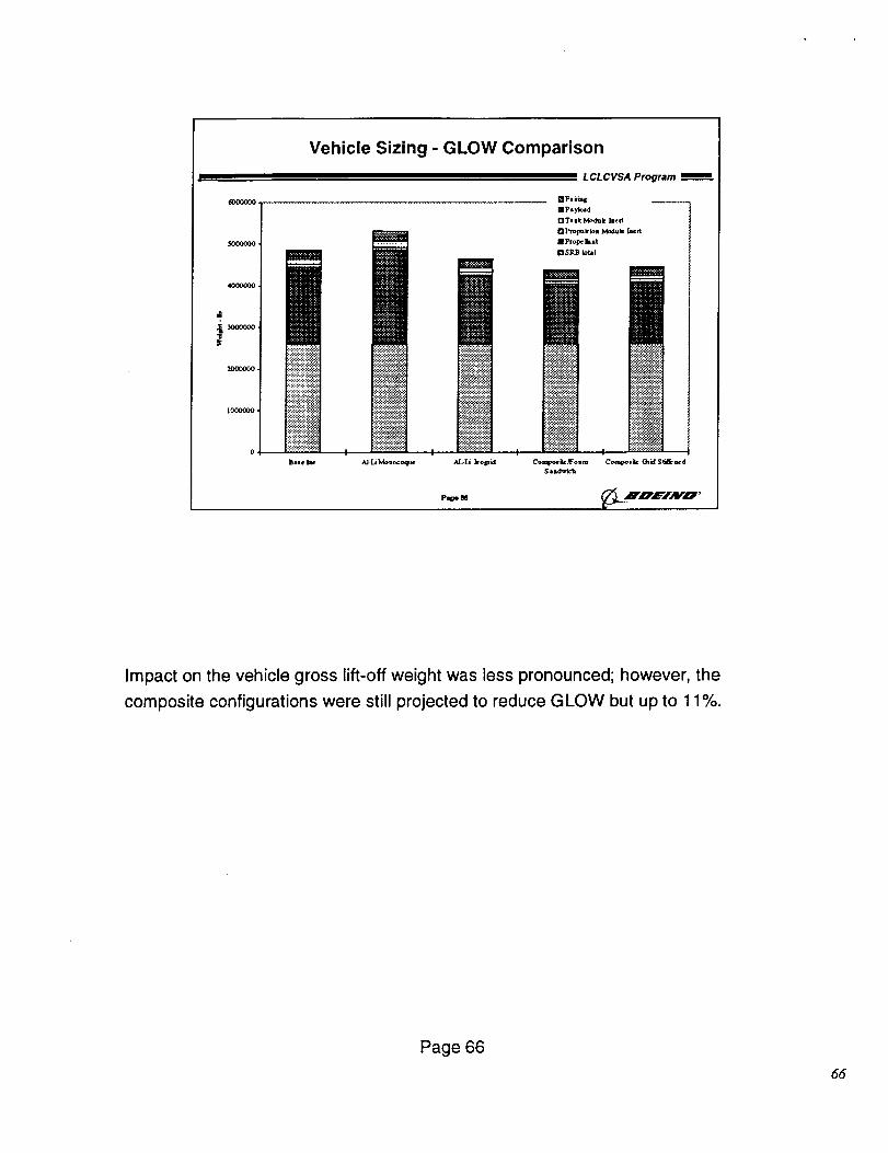
Impact on the vehicle gross lift-off weight was less pronounced; however, the
composite configurations were still projected to reduce GLOW but up to 11%.
Page 66
66
Cost Estimation Method
LCLCVSA Program __
O Vehicle and element costs estimated for baseline
design using a parametric approach (NAFCOM)
O Core structures for each concept estimated using
"bottoms-up" (BCM) approach
Factor applied to BCM estimates to reconcile with
the parametric estimate• Accounts for items not included in BCM estimate
• Factor adjusted for relative complexity of each concept
D NAFCOM used to develop full vehicle cost estimate
• Adjusted BCM estimates fed in as pass-through items
• Other items adjusted to reflect the change in vehicle size
- TPS, wiring, propulsion lines, etc.
- Main engines not changed
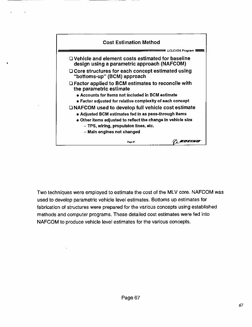
Two techniques were employed to estimate the cost of the MLV core. NAFCOM was
used to develop parametric vehicle level estimates. Bottoms up estimates for
fabrication of structures were prepared for the various concepts using established
methods and computer programs. These detailed cost estimates were fed into
NAFCOM to produce vehicle level estimates for the various concepts.
Page 67
67
Items Not Included in Detailed Cost Estimates
L CLCVSA Program
[] Structural Details
• Slosh baffles
• LH2 tank SRB attachment structure
Q Fabrication tooling and ground support equipment
[] Subsystem integration and check-out
[] Program management and other overhead costs
n, F/,_vo '
The scope of the study precluded inclusion of all relevant details. These were
accounted for by application of an adjustment factor prior to development of the
NAFCOM full vehicle estimate.
Page 68
68
Cost Estimation Groundrules
LCLCVSA Program
Q All costs were estimated in constant 1997 $ using NASA escalation Indices.
No fee or contingency was Included and G&A was assumed to be 10%.
Q No operations costs or facilities were Included. DDT&E was reduced 32.8%
and mfg. T#1 was reduced 25% to account for class I changes that are Inthe model's data. These reductions were not taken on throughput costs
from BCM, off the shelf hardware, or systems costs.
CI The APUs, fairing separation and main e_gines were throughput costs
from quotes (APUs) or historical data (separation and SSME).
Q A 90% learning curve was assumed for all hardware estimatad by NAFCOMor BCM estimates. 95% learning was assumed for off the shelf hardware
(APUs, SSMEs, separation). The annual production rate was (; units, with a
total program buy of 60 units.
Q Because of the unique nature of the semi-reusable concept under study, Itwas necessary to make the manufacturing estimate In 2 separate runs.
The first had DDT&E, STH (does not fly) and two units of production of allthree major elements (propulsion module (p/m), tank, fairing). The second
run had 58 units of tanks and falrlngs starting at unit 3.
Q The engines for the test p/m were assumed to be used engines and did not
contain the 30% factor added to newly designed hardware for STH. New
engines were assumed for the 2 production p/re. No refurbishment cost forthe engine between flights was Included from the model. No engine designcost was Included.
w
This space intentionally left blank.
Page 69
59
NAFCOM Cost Estimation Groundrules
LCLCVSA Program
O When running the NAFCOM model with BCM throughputs, this had anImpact on systems costs. The estimate was taken outside the model and
the systems costa were left as generated from the model using aluminumhardware.
QI Subsystems and components other than composite structures wereestimated using the weight for that configuration. The design estimate for
composite components was estimated with the weight of the baselinealuminum componenL
D In a separate run of the model the second p/m per flight set was accountedfor by putting through the cost of a second plm as a separate componenL
This was necessary since NAFCOM does not allow Input of different
quantities of hardware and some of the weight (ex. Main Propulsion) was
estimated as a subsystem with Main Propulsion in the Tank Module. Thisallowed us to get the recurring support cost of Integrating the second PMto the launch vehicle.
0 No complexity Judgments were made other than what Is Implicitly assumed
in the choice of data points and adjustment of the BCM estimates.
I_ Non structure subsystems were estimated as whole subsystems. In order
to present the estimate for p/m, tank module, and fairing; the estimates forwhole subsystems were distributed by weight outside the model.
17 For more Information about how the estimate was derived see the attached
sheet which shows the platform and data point numbers assum_,.d for eachcomponent / subsystem. P,0, 70 _J,.._i'_L_#'AYO '
This space intentionally left blank.
Page 70
7o
Structures Cost Estimate Summary
L CL C VSA Program
+'tiiHiii_A 7o_
30% t
10%
0% 4AFU Monencc_ue
,°°.]--.-i_..................................................................................................[].,r_o90% I_ Aft Skid
0 Fwd Struct
i:_$i:i:_:i:..-...........::_:::::_:::
::::::::::::::
A_LJ ho_lfid
Dlntedank[] Lox Tank
[] Fu_ Tank
.>:.:.:.:.:-."
.....=.:.-.:.:.:.:.:*:.:.
@
..............::.::.:i:.:::.:i::"
I_llg111 __.IOEINO"
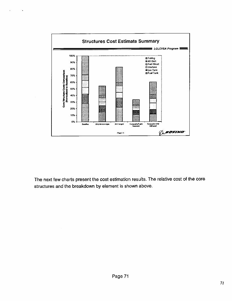
The next few charts present the cost estimation results. The relative cost of the core
structures and the breakdown by element is shown above.
Page 71
7]
Structure Costs vs. Vehicle costs(normalized to vehicle baseline cost)
LCLCVSA Program
I NAFCOM Estimated !_=
VehicleCost reductions
1.00
S !iliiiiii_i 1%
o iiii;iii_iii 'o !iiii_i_iiii
0.80 !_iii_i_iii_
.:.:.:.:.:.:
.,..,..,..,.
.:.:.:.:.:.:,....,....,.
] 060 i!!!i!iiii
=>o iiiiiii_iii
_i i!ii!!!!!i_io.4_o.,o, iiiii ii:
,..,... ........
- iii!ilililiiiiiiiMiiiil0.20. ;i;i;i;i;i;i;iiiiiiiiiiiiil
i:!.-'.:!:!i!:!iiiiiiiiiiii_liii!i!iii!i!!!!!!ii!_j
,....,..0.00 ...... '' "
BaNline
0.8_
,.-..,.....
.:.:.:.7,.:
:.:+:.:.:,
• .:.:.:.:.:
.::Ji.i.i.:::!:.:::':i:!:i
.:.:.>:.:.:iiii!i!i_i
..,..,....,.
ii::#:!iiii$?._:i:!:,.......,...
/_-Li Mononcoque AJ-Li I._ogrid
i.,Izge rz
{3 Total Vehicle Costs
[] Structure Fab Costs
_ _'_ 11%_0.80
0.82 i _
iiiiii[iiii
iiiiiiiiiii...,,
i_iii
iii ii!il,i,_::iiiii::ii:
Conr_oosite/Foam Composite Grid
Sandwich Stiffened
_L.R, mf'IAFO"
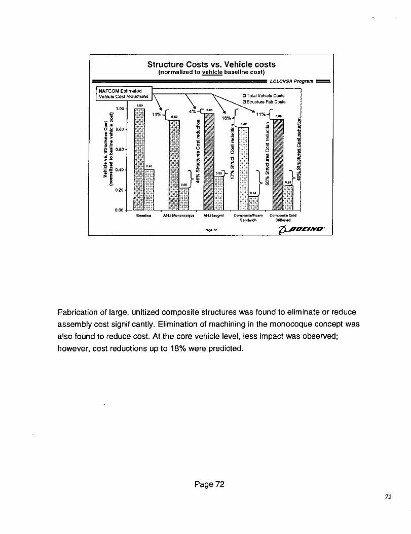
Fabrication of large, unitized composite structures was found to eliminate or reduce
assembly cost significantly. Elimination of machining in the monocoque concept was
also found to reduce cost. At the core vehicle level, less impact was observed;
however, cost reductions up to 18% were predicted.
Page 72
?2
Grid Stiffened Composite Competitive for Tanks
LCLCVSA Program
T6r_l
A_
M_d
1
DrYSV_'ZJrO_%
i O.|
Fo_ 0.6 °
Si_lwlch
':itkW_d
D_ _ _
,.2..................................................,;_;_;'i:,1_................• Compodl_:oem S4mdwfch
• Compodb Odd S_Mfw_d
iTar_ Dry Stucturo
Page 7"3 _n,c=-iAV'O '
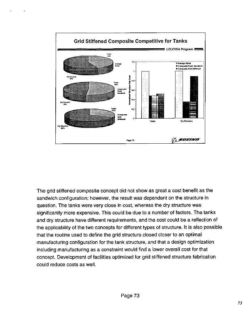
The grid stiffened composite concept did not show as great a cost benefit as the
sandwich configuration; however, the result was dependent on the structure in
question. The tanks were very close in cost, whereas the dry structure was
significantly more expensive. This could be due to a number of factors. The tanks
and dry structure have different requirements, and the cost could be a reflection of
the applicability of the two concepts for different types of structure. It is also possible
that the routine used to define the grid structure closed closer to an optimal
manufacturing configuration for the tank structure, and that a design optimization
including manufacturing as a constraint would find a lower overall cost for that
concept. Development of facilities optimized for grid stiffened structure fabrication
could reduce costs as well.
Page 73
?3
Trade Study Conclusions
L CL C VSA Program
[] Unitized composite structures offer major benefitsin both cost and weight
[] Even major reductions in structures costs aloneare insufficient to meet NASA goal of $175M/flt
• Engine, SRB and operations costs must also be reduced
• LFBB projected to save $500M/yr on orbiter (7 flt/yr)
[] Technology and design Improvements wouldimprove the performance of some concepts
• High speed machining
• AGS design for produclbility
• Multiple head FP
plge 74 _r, crz=TAv'o'
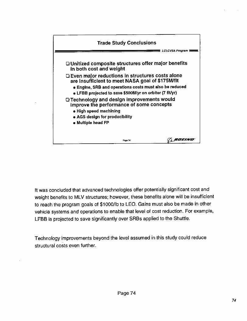
It was concluded that advanced technologies offer potentially significant cost and
weight benefits to MLV structures; however, these benefits alone will be insufficient
to reach the program goals of $1000/Ib to LEO. Gains must also be made in other
vehicle systems and operations to enable that level of cost reduction. For example,
LFBB is projected to save significantly over SRBs applied to the Shuttle.
Technology improvements beyond the level assumed in this study could reduce
structural costs even further.
Page 74
?4
Recommended Future Work
L CL C VSA Program
O More in-depth study of high-payoff composite
concepts
• Tooling
• Impact of further technology advances
• More detailed cost and weight assessment
O Systems level study to optimize vehicleconfiguration
0 Operations study to identify potential costsavings
Page 75 _. ,ID, L='/AFO•
In addition to the technology and facilities developments laid out in Task 3, we also
recommend further study to refine the fidelity of these preliminary estimates,
consider vehicle configuration changes, and identify areas for cost savings in
operations.
Page 75
75
Thrust Structure Assessment
L CL C VSA Program
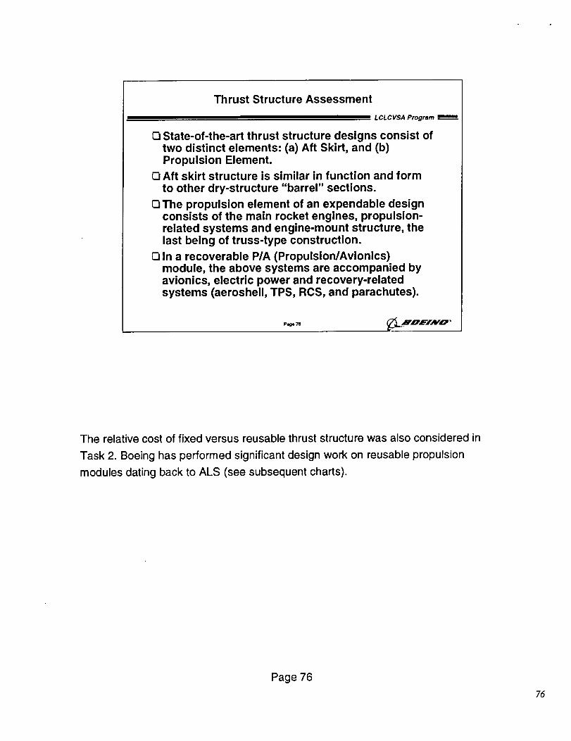
O State-of-the-art thrust structure designs consist oftwo distinct elements: (a) Aft Skirt, and (b)Propulsion Element.
E] Aft skirt structure is similar in function and form
to other dry-structure "barrel" sections.
Cl The propulsion element of an expendable designconsists of the main rocket engines, propulsion-related systems and engine-mount structure, thelast being of truss-type construction.
E] In a recoverable P/A (Propulsion/Avionics)module, the above systems are accompanied byavionics, electric power and recovery-relatedsystems (aeroshell, TPS, RCS, and parachutes).
Page 745 ._L.mnE/Awo '
The relative cost of fixed versus reusable thrust structure was also considered in
Task 2. Boeing has performed significant design work on reusable propulsion
modules dating back to ALS (see subsequent charts).
Page 76
76
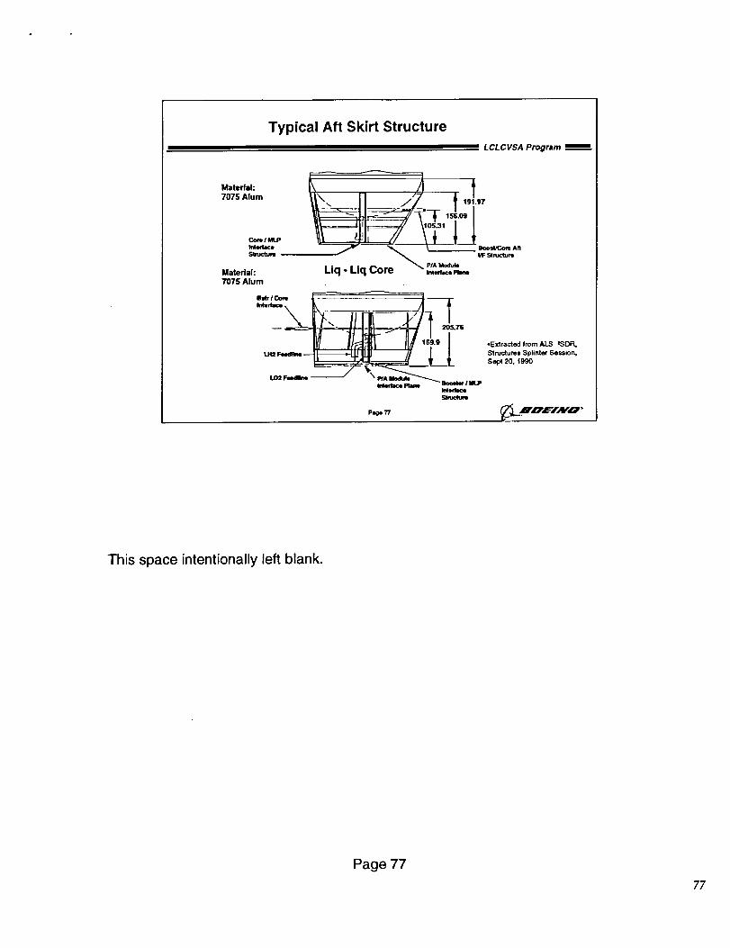
Typical Aft Skirt Structure
L CL C VSA Program
Material:
7075 Alum
stRmtu_ IIF Stt_clum
Material: Liq - Liq Co p_Ak_edace
7075 Alum
Imw_ceSu_ctu_
P_77
*Extracted from ALS =SDR,Structures Splinter Session,
Sept 20, 1990
__..H,_,f'iAV'O"
This space intentionally left blank.
Page 77
77
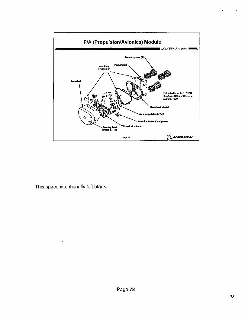
P/A (Propulsion/Avionics) Module
L CL C VSA Program
Zti_ _ ___ StE_au_ee_s _i_t/N_Se sZSs_Rn:
__ Sept 20. 1990IBam INNit =tdeld
P_, 7S _,..B'_',CrlAIrO '
This space intentionally left blank.
Page 78J
?8
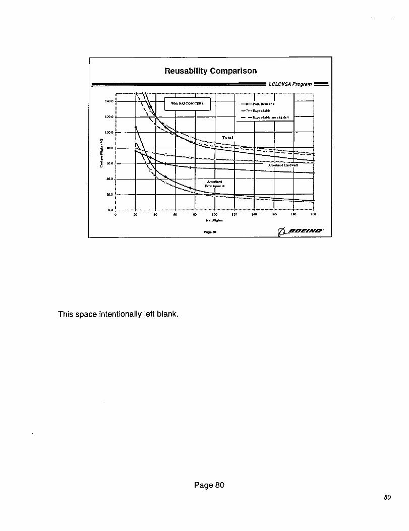
Reusability Trade Results
= LCLCVSA Program
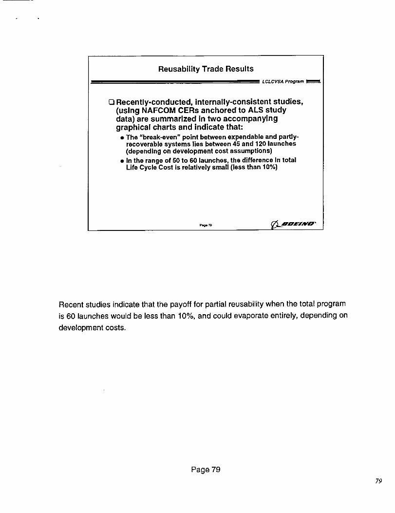
Q Recently-conducted, internally-consistent studies,(using NAFCOM CERs anchored to ALS studydata) are summarized in two accompanyinggraphical charts and indicate that:
• The "break-even" point between expendable and partly-recoverable systems lies between 45 and 120 launches(depending on development cost assumptions)
• In the range of 50 to 60 launches, the difference in totalLife Cycle Cost is relatively small (less than 10%)
piioe 79 _L .HnEIA v"O '
Recent studies indicate that the payoff for partial reusability when the total program
is 60 launches would be less than 10%, and could evaporate entirely, depending on
development costs.
Page 79
?9
140.0
120.0
tO0.O
" I0.0
Reusability Comparison
O_ .! ..............
0 20
W'_ N_COM CER_= |
I
40 60 IO 100 120
No. ]rll I bb
Pege _O
L CL CVSA Program
[ I-,--41,-_P a _ _us tbk
_Exp_ ndambk, mmo¢ ag dc v
140 160 lgO 2(]0
This space intentionally left blank.
Page 80
8O
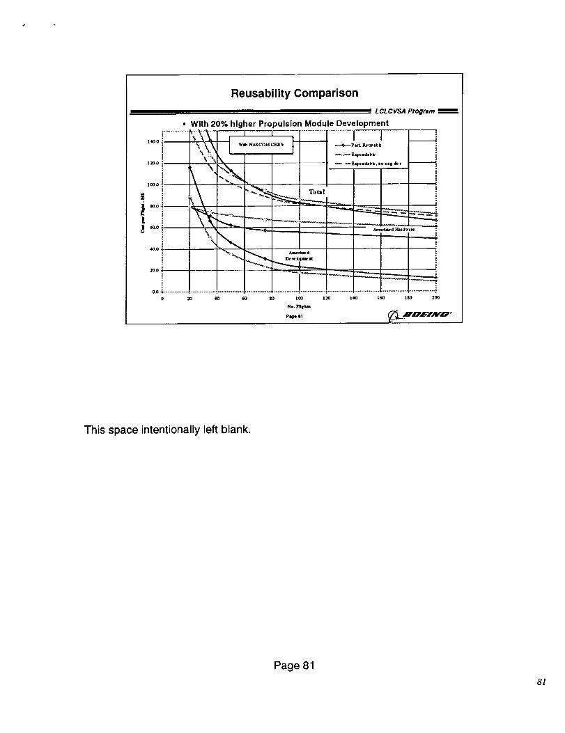
Reusability Comparison
With 20% higher Propulsion Module Development
J .... _ ......
" _ Total
1
LCLCVSAProgram
0 20 40 60
.--..,_.-p aft. Real lbk
_:::_ E;q>esdabk
_EXpClSdabk, |0 ¢|g de v
Amo_t=ed
14) 100 120 140
N*. Yllskta
Page 81
Amo_d Hardware i
i
..............i
160 180 200
__.IOEIAV'O '
This space intentionally left blank.
Page 81
8/
LFBB
LCLCVSA TECHNOLOGY APPLICATIONS TO LFBB
Members of the Boeing LFBB program in Downey, CA evaluated theMLV trade study concepts for applicability to the LFBB system. Thisstudy involved quick estimation of impact on both weight and cost of the
advanced technology concepts as compared to the LFBB baseline.
82
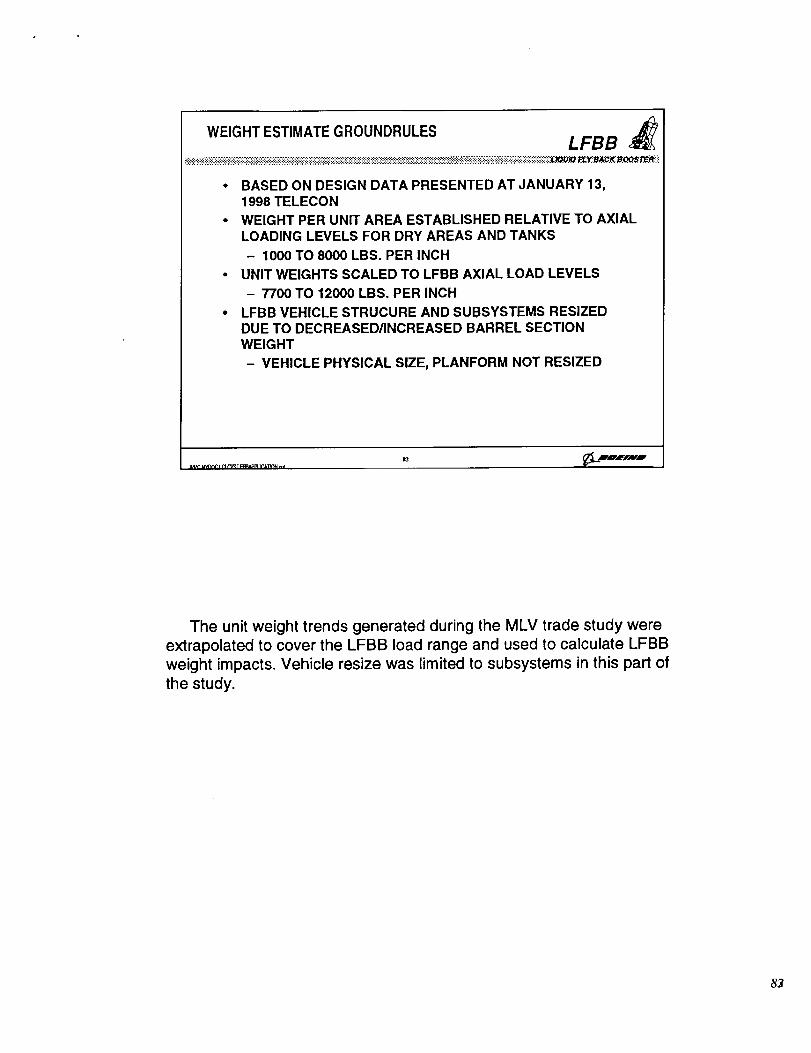
WEIGHT ESTIMATE GROUNDRULES LFBB
• BASED ON DESIGN DATA PRESENTED AT JANUARY 13,1998 TELECON
• WEIGHT PER UNIT AREA ESTABLISHED RELATIVE TO AXIALLOADING LEVELS FOR DRY AREAS AND TANKS
- 1000 TO 8000 LBS. PER INCH
• UNIT WEIGHTS SCALED TO LFBB AXIAL LOAD LEVELS
- 7700 TO 12000 LBS. PER INCH
• LFBB VEHICLE STRUCURE AND SUBSYSTEMS RESIZEDDUE TO DECREASED/INCREASED BARREL SECTIONWEIGHT
- VEHICLE PHYSICAL SIZE, PLANFORM NOT RESIZED
The unit weight trends generated during the MLV trade study wereextrapolated to cover the LFBB load range and used to calculate LFBB
weight impacts. Vehicle resize was limited to subsystems in this part ofthe study.
8_
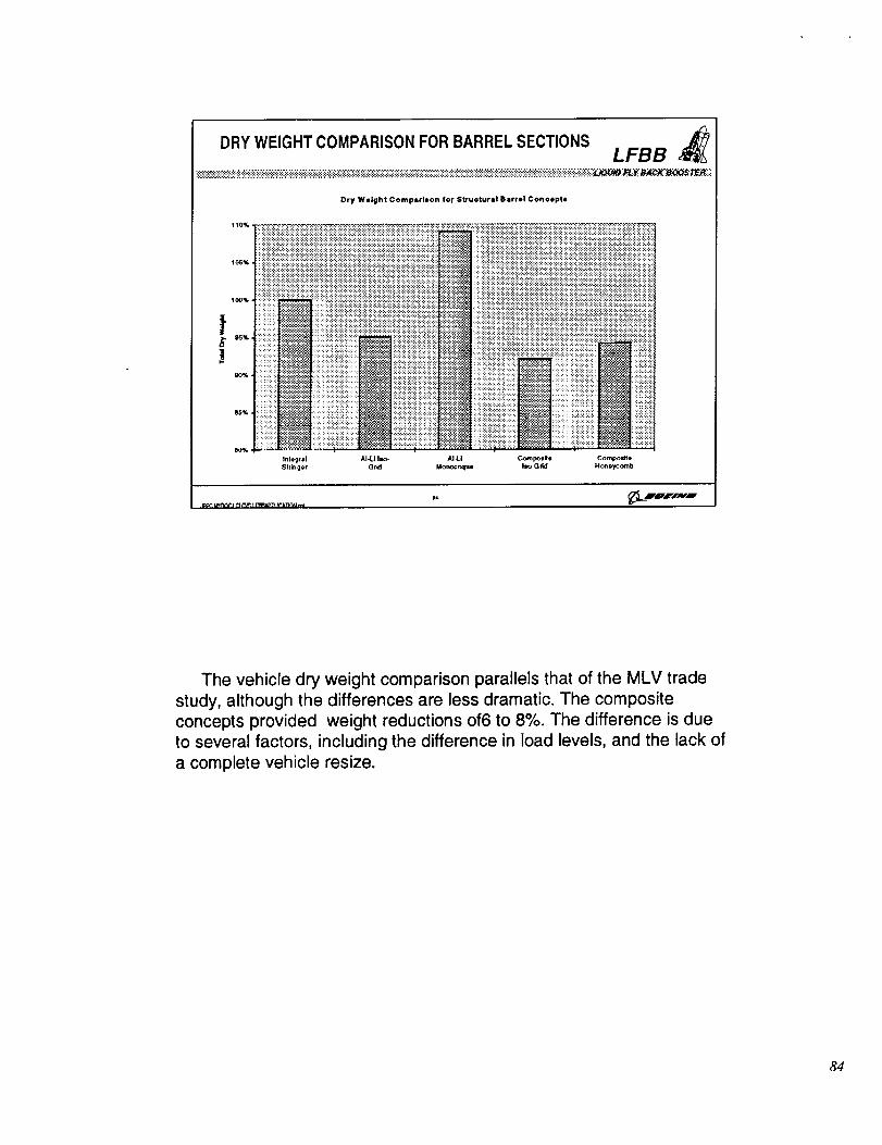
DRY WEIGHT COMPARISON FOR BARREL SECTIONS LFBB
Dry Weight Compsrlson for $tructursl Barrel Conoopta
iiiiiiiiil .........................iii;iiii iiiiiiiiiiiiiii!
,,,. iiiiiii iili_i i;ili;i::iiiiili!::;ii:.!i!i!il iiii!i!iiiii!ili!!!iii!i!i :ililiiii!i
)::!i!::.i_i_iiiN ::iii::i::ii!ili}:.i!i::!':ili::_i ;_:::.i::iii!_iii:-i::iiiiii::;i ::;;i!:.!::ii!i!i!i!ii !}i!_!i!i!:.iBO%
Inleg_il AI-U Iso- AI4-| Cot_po_le Com_eStrbger Grid Monocoque I=o=Gdd Honeycomb
The vehicle dry weight comparison parallels that of the MLV trade
study, although the differences are less dramatic. The composite
concepts provided weight reductions of 6 to 8%. The difference is due
to several factors, including the difference _n load levels, and the lack of
a complete vehicle resize.
84
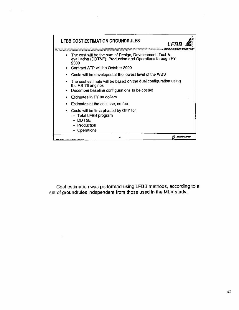
LFBB COST ESTIMATIONGROUNDRULES LFBB
• The cost will be the sum of Design, Development, Test &evaluation (DDT&E); Production and Operations through FY2030
• Contract ATP will be October 2000
• Costs will be developed at the lowest level of the WBS
• The cost estimate will be based on the dual configuration usingthe RS-76 engines
• December baseline configurations to be costed
• Estimates in F'Y98 dollars
• Estimates at the cost line, no fee
• Costs will be time phased by GFY for- Total LFBB program- DDT&E- Production
- Operations
LBgIJHI
Cost estimation was performed using LFBB methods, according to a
set of groundrules independent from those used in the MLV study.
85
a3,
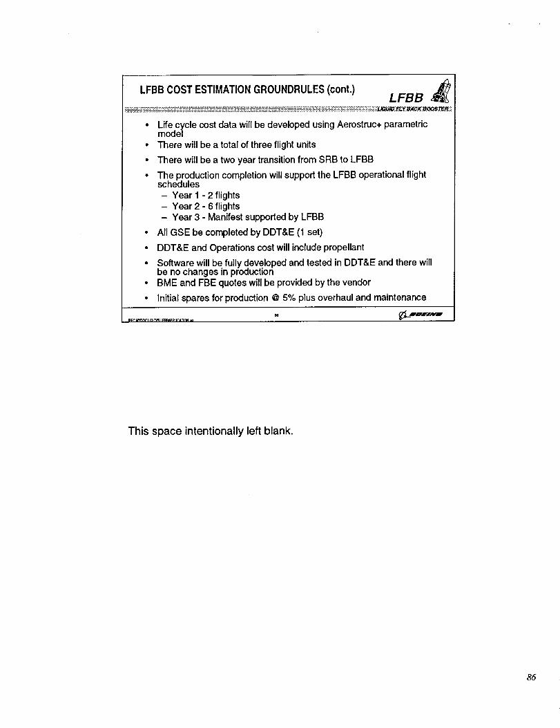
LFBB COST ESTIMATION GROUNDRULES (cont.) LFBB _J_
• Life cycle cost data will be developed using Aerostruc+ parametricmodel
• There will be a total of three flight units
• There will be a two year transition from SRB to LFBB
• The production completion will support the LFBB operational flightschedules- Year 1 - 2 flights- Year 2 - 6 flights- Year 3 - Manifest supported by LFBB
• All GSE be completed by DDT&E (1 set)
• DDT&E and Operations cost will include propellant
• Software will be fully developed and tested in DDT&E and there willbe no changes in production
• BME and FBE quotes will be provided by the vendor
• Initial spares for production @ 5% plus overhaul and maintenance
_= _DOff N4 P'
This space intentionally left blank.
86
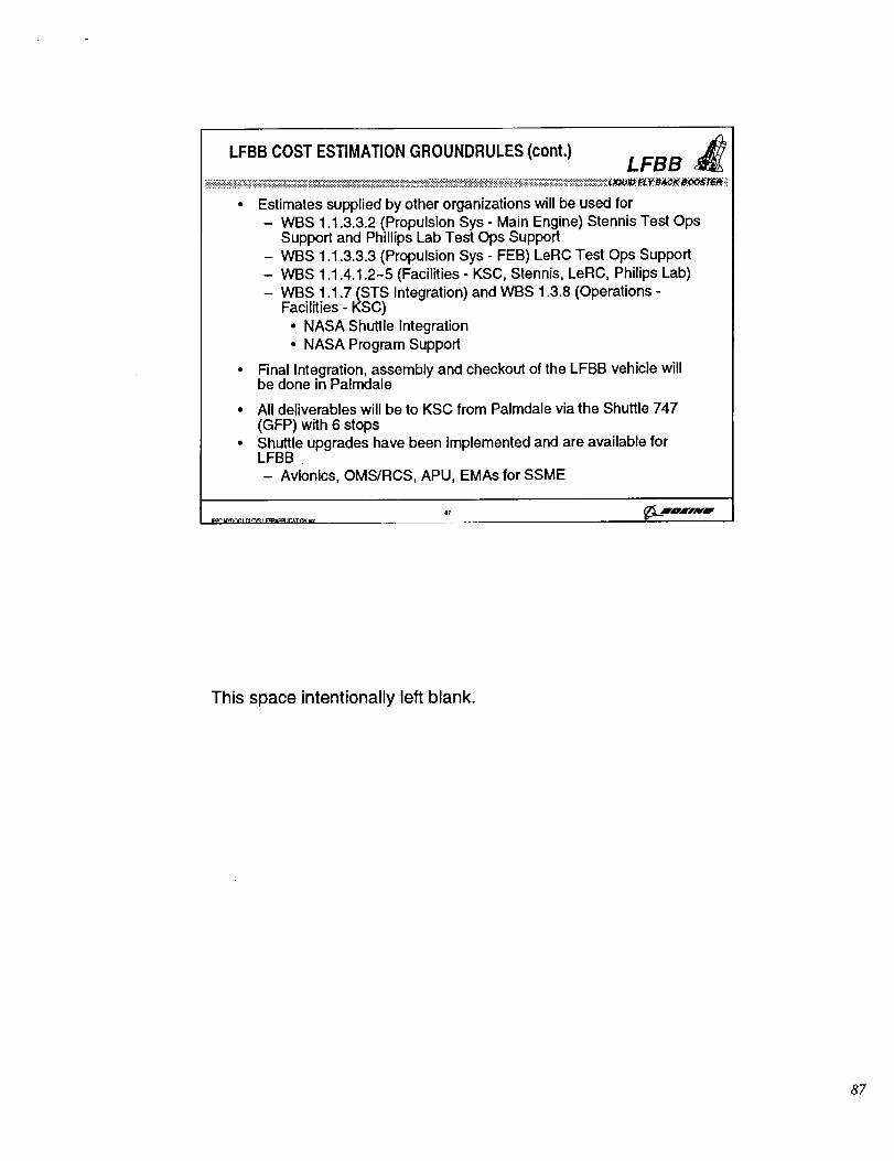
..(3.LFBB COST ESTIMATION GROUNDRULES (cont.) LFBB
• Estimates supplied by other organizations will be used for- WBS 1.1.3.3.2 (Propulsion Sys - Main Engine) Stennis Test Ops
Support and Phillips Lab Test Ops Support- WBS 1.1.3.3.3 (Propulsion Sys - FEB) LeRC Test Ops Support- WBS 1.1.4.1.2-5 (Facilities - KSC, Stennis, LeRC, Philips Lab)- WBS 1.1.7 (STS Integration) and WBS 1.3.8 (Operations -
Facilities - KSC)• NASA Shuttle Integration• NASA Program Support
• Final Integration, assembly and checkout of the LFBB vehicle willbe done in Palmdale
• All deliverables will be to KSC from Palmdale via the Shuttle 747(GFP) with 6 stops
• Shuttle upgrades have been implemented and are available forLFBB- Avionics, OMS/RCS, APU, EMAs for SSME
This space intentionally left blank.
87
LFBB Cost Trade Using AEROSTRUC+ Model LFBB #_
11i
!
m$:.:i:!::.:!:!:':;!
i':i:"i'.:i.:ii:'iiiii
_:::::::::::::::
I _ogdd Co_pooa _ _ _dlo Grid SHBI_¢_,_I
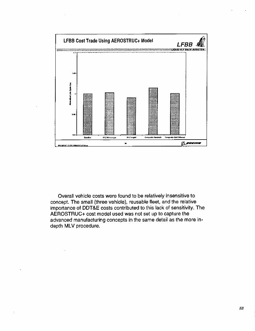
Overall vehicle costs were found to be relatively insensitive to
concept. The small (three vehicle), reusable fleet, and the relative
importance of DDT&E costs contributed to this lack of sensitivity. The
AEROSTRUC+ cost model used was not set up to capture the
advanced manufacturing concepts in the same detail as the more in-
depth MLV procedure.
88
a_L
LFBB ASSESSMENT CONCLUSIONS LFBB
• LFBB results distinct from MLV
- Different scale
- Different loads and requirements
- Reusable system
• Less sensitivity to concept observed in LFBB comparison
- Performance benefit evident for composite concepts
- Costs of concepts indistinguishable
- Vehicle resize not performed
- Cost estimation technique did not capture advancedmanufacturing approaches
• Many technical elements can be ready to support LFBBdevelopment and production
Despite limitations on the scope of the LFBB evaluation, it isapparent that performance benefits would accrue from inclusion of
advanced technology concepts. While the cost benefits of thesetechnologies were not conclusive, it would appear that at a minimum,there is no cost penalty. As will be shown in the next section, many ofthe technology developments necessary to include these concepts in
LFBB can be accomplished within the required schedule.
89
Task 3 - Development Roadmaps
LCLCVSA Program
Section Topics:
O Existing capital equipment and facilities
• Boeing facilities around the US
• NASA facilities for ET production
O Technology and facility development roadmaps
• High payoff technologies evaluated in trade study
• Enhancing technologies for additional payoff
• Facility development requirements
O Current and planned technology development
programs
Task 3 focused on identification of existing facilities for MLV core structures
production, technology and facilities development requirements to support MLV and
LFBB, and programs which support those requirements.
Page 90
Manufacturing Plan Overview
L CLCVSA Program
O Metallic Concepts Manufacturing
• Vertical barrel section assembly
• Horizontal element assembly
• Barge to major structures to launch site
• Vertical assembly at launch site (use VAB at KSC)
O Composite Concepts Manufacturing• Vertical fabric/tow placement & vacuum bag/cure
- Reduces tooling stiffness requirements
- Building height issues
- Optional horizontal autoclave cure
• Barge to major elements to launch site
• Vertical assembly at launch site (use VAB at KSC)
Page @1 _. maEIAYO"
The overall manufacturing flow would be similar for either metallic or composite
MLV core structures. The core elements would be fabricated, then shipped to KSC
for vehicle assembly. Due to the size of the elements, vertical fabrication minimizes
stiffness concerns, but raises issues regarding facilities. A major issue would be the
availability of autoclave facilities able to accommodate MLV scale structures. Non-
autoclave cure technology is an attractive alternative.
Page 91
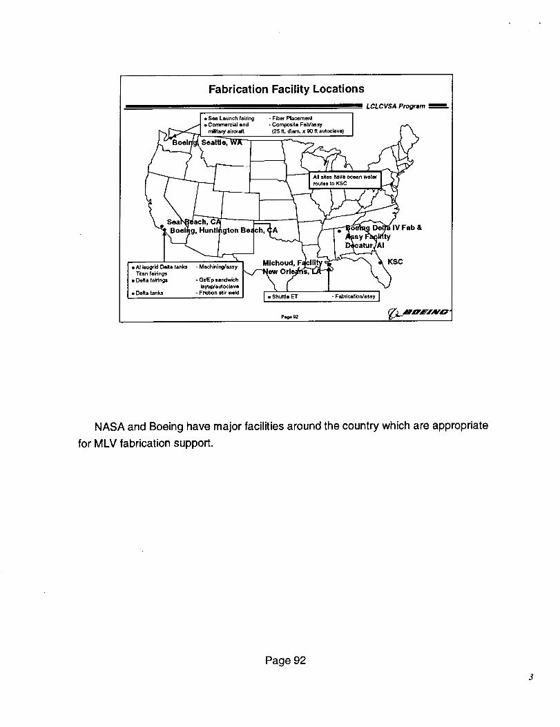
Fabrication Facility Locations
i i LCLCVSA Program
/ • Sea Launch fairing - Fiber Placernent I_ _ • Commercial and - Composite Fab/assy I
[_/._ r_litary air,aft (25 ft. diam. x 90 ft aut_lave) I I
_" oe g, Huntl gton Be h,
Titan fairings• Deita fatrtngs -G_p,_ch I \ f \ I
• Deita tanks - Friction stir weld I • Shuttle ET - Fabdcation/a._y JB
_.L ZrnE/Av'o •P_ _
NASA and Boeing have major facilities around the country which are appropriate
for MLV fabrication support.
Page 92
Locations & Products
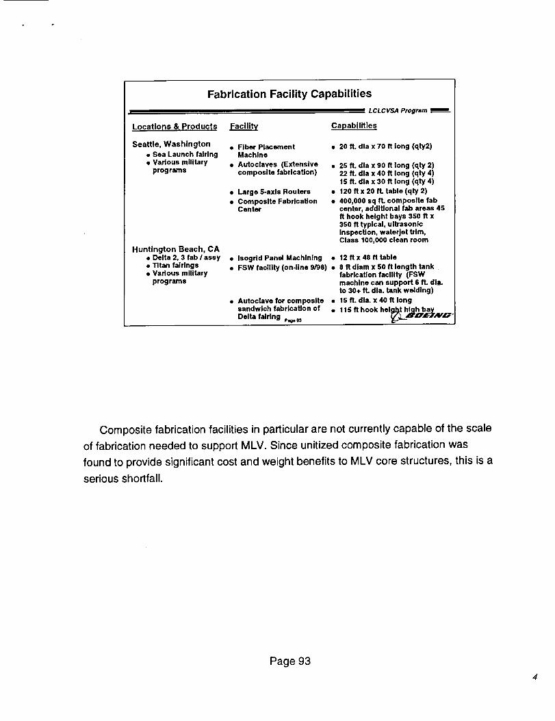
Fabrication Facility Capabilities
LCLCVSA Program
FacilihL Capabilities
Seattle, Washington
• Sea Launch fairing• Various military
programs
Huntington Beach, CA• Delta 2, 3 fab / assy• Titan tairlngs• Various military
programs
• Fiber PlacementMachine
• Autoclaves (Extensivecomposite fabrication)
• Large 5-axis Routers •
• Composite Fabrication •Center
• 20 ft. dla x 70 ft long (qty2)
25 ft. dla x 90 ft long (qty 2)22 ft. dla x 40 ft long (qty 4)15 ft. dla x 30 ft long (qty 4)
120 ft x 20 ft. table (qty 2)
400,000 sq ft. composite tabcenter, additional tab areas 45ft hook height bays 350 ft x350 ft typical, ultrasonicInspection, waterjet trim,Class 100,000 clean room
• Isogrid Panel Machining • 12 ftx 48 ft table• FSW facility (on-line 9/98) • 8 ft diam x 50 ft length tank
fabrication facility (FSWmachine can support 6 ft. dla.to 30+ ft. dla. tank welding)
• Autoclave for composite • 15 ft. dla. x 40 ft longsandwich fabrication of • 11S ft hook helglJ31high bay
_.L_zrU, eTAYn"Delta fairing p,_
Composite fabrication facilities in particular are not currently capable of the scale
of fabrication needed to support MLV. Since unitized composite fabrication was
found to provide significant cost and weight benefits to MLV core structures, this is a
serious shortfall.
Page 93
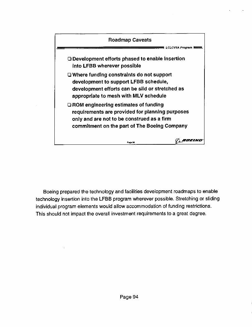
Roadmap Caveats
L CL C VSA Program
O Development efforts phased to enable Insertion
into LFBB wherever possible
O Where funding constraints do not support
development to support LFBB schedule,
development efforts can be slid or stretched as
appropriate to mesh with MLV schedule
O ROM engineering estimates of funding
requirements are provided for planning purposes
only and are not to be construed as a firm
commitment on the part of The Boeing Company
Plge 94
Boeing prepared the technology and facilities development roadmaps to enable
technology insertion into the LFBB program wherever possible. Stretching or sliding
individual program elements would allow accommodation of funding restrictions.
This should not impact the overall investment requirements to a great degree.
Page 94
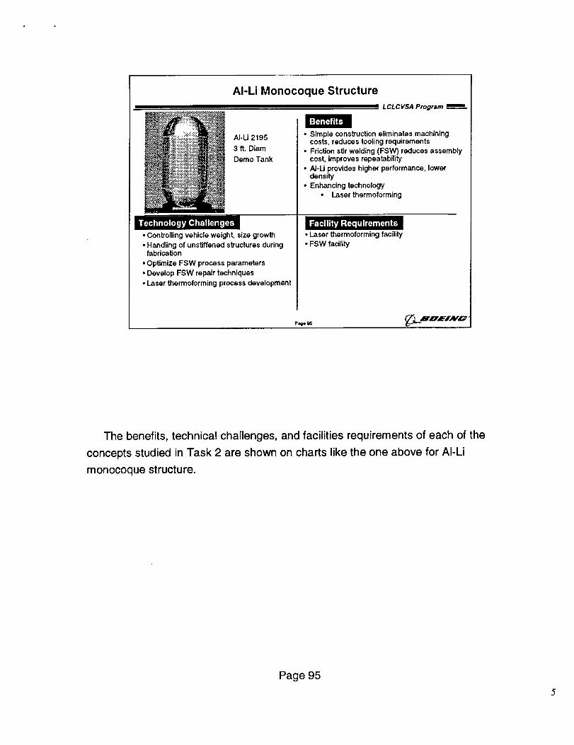
AI-Li Monocoque Structure
L CL C VSA Program
'_ _'i::::_i::iiiii:-'_:/:ii::_i_i __•". Al-li 2195
• ::_.ii!i_i_i_ii_!!i: .:<"
._?_:._._ .
_..:;.:_.__:!::-!!! ,-.
• Controlling vehicle weight, size growth
• Handling of unstiffened structures duringfabrication
• Optimize FSW process parameters
• Develop FSW repair techniques
• Laser thermoforming process development
Benefits
• Simple construction eliminates machiningcosts, reduces tooling requirements
• Friction stir welding (FSW) reduces assemblycost, improves repeatability
• AJ-U provides higher performance, lower
density
• Enhancing technology
• Laser thermoforming
• Laser thermoforming facility
• FSW facility
The benefits, technical challenges, and facilities requirements of each of the
concepts studied in Task 2 are shown on charts like the one above for AI-Li
monocoque structure.
Page 95
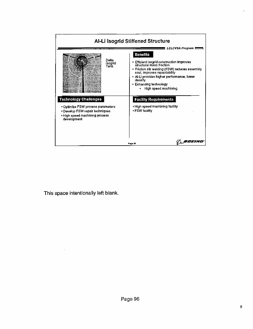
AI-Li Isogrid Stiffened Structure
L CL C VSA Program
Benefits: • _;:.':.:_:_..:.%<--
Delta
-:i_._ __.:.:i_!i-i::__,.."$.:_anO_id• _ ..:_:..._,$_. .:::,-_.:::::_i._.:.. •_ . -.._._.', ...:_.:,:_-.._..-:._
-:_.:,_.{_j::._:.,..........,..............__ ..<.._e_:..,'._....,........+.....:.:,_.:>..:_._.._:_'._.._
I I'T'_,l,[.] [.z,},_Ld;'_ I[:.]_[, [:-]-'i:
• OptimizeFSW process parameters• Develop FSW repair techniques
• High speed machining process
development
• Efficient isogrid construction improvesstructural mass fraction
• Friction stir welding (FSW) reduces assemblycost, improves repeatability
• AI-Li provides higher performance, lowerdensity
• Enhancing technology
• High speed machining
l _-_ iff_Fi _,(=[, UI I_[:]H [:-]=l.(-'ll
• High speed machining facility
• FSW facility
Pl=ge _/_LZ='UEIAVO
This space intentionally left blank.
Page 96
6
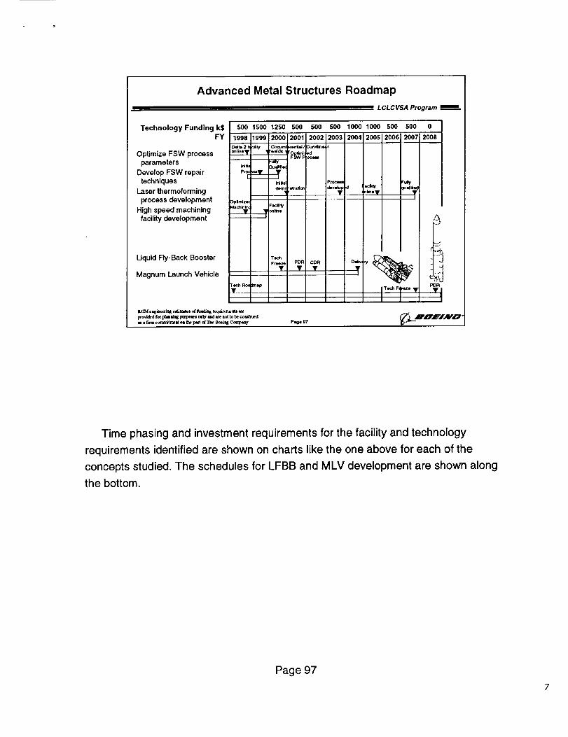
Advanced Metal Structures Roadmap
L CL C VSA Program
Technology Funding kSFY
Optimize FSW process
parameters
Develop FSW repair
techniques
Laser thermoforming
process development
High speed machining
facilitydevelopment
Uquid Fly-Back Booster
Magnum Launch Vehicle
500 1500 1250 500 500 0
1998 1999 2OOO
D_ta 2 fi _Jity Cifcum
onlinev _ ,w_d=.__._,
_uily_Qia :3uall, e<
IN_al
_(
Oplmlze<Facai_
I
T_
Freeze
500 500 1000 1000 500
2001 2002 2003 2004 200512006
stre|on
Proc_
deve_ :f =dlitynl_e •
2007 2008
ualiled
I
PDR CDR Ddl_
!
PDR
Time phasing and investment requirements for the facility and technology
requirements identified are shown on charts like the one above for each of the
concepts studied. The schedules for LFBB and MLV development are shown along
the bottom.
Page 97
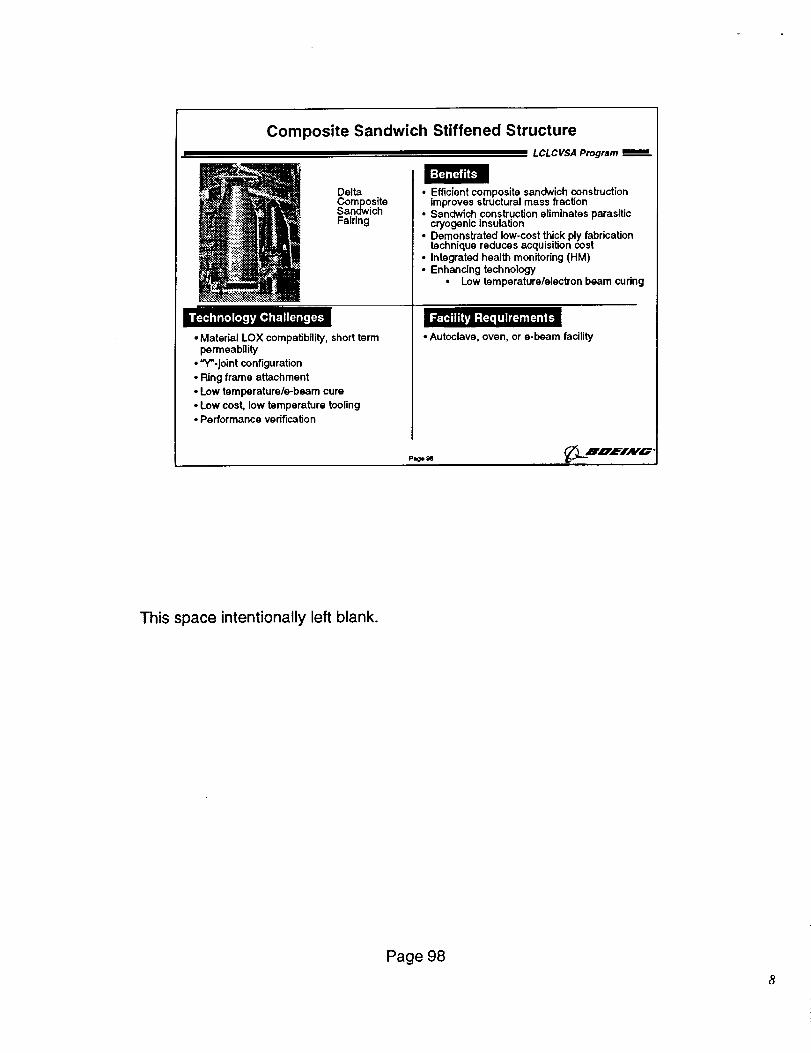
Composite Sandwich Stiffened Structure
LCLCVSA Program
Benefits
DellaCompositeSandwichFairing
B[_I'_,],H[.z_L,Ad,TIi [=_,z,[_-=
• Material LOX compatibility, short termpermeability
• "Y_-joint configuration• Ring frame attachment
• Low temperature/e-beam cure• Low cost, low temperature tooling• Performance verification
• Efficient composite sandwich constructionimproves structural mass fraction
• Sandwich construction eliminates parasiticcryogenic Insulation
• Demonstratecl. low-cost thick ply fabricationtechnique reouces acquisition cost
• Integrated health monitoring (HM)• Enhancing technology
• Low temperature/electron beam curing
• Autoclave, oven, or e-beam facility
P=O*_ _'LRUfi,_'"
This space intentionally left blank.
Page 98
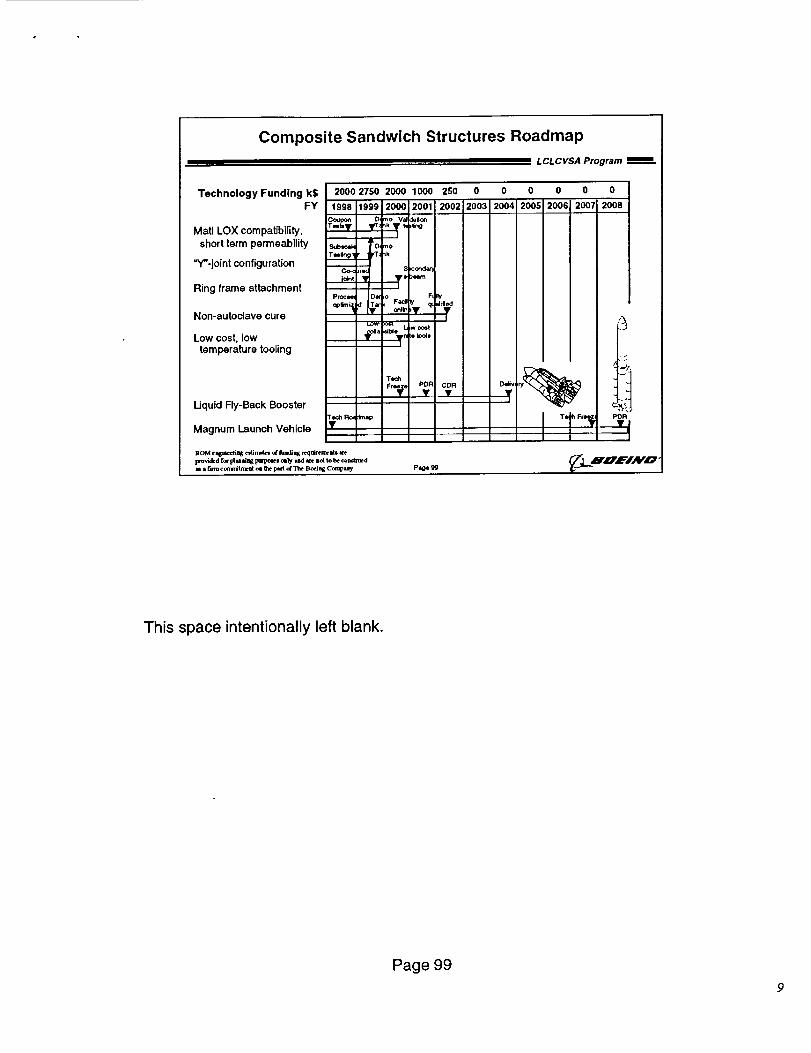
Composite Sandwich Structures Roadmap
LCLCVSA Program
Technology Funding kS 2000 2750 2000 1000 250 0 0 0 0
FY 2003 2004 2005 2006
Matl LOX compatibility,
short term permeability
"Y'-joint configuration
Ring frame attachment
Non-autoclave cure
Low cost, low
temperature tooling
1998 1999 2000 2001 2002
O, ¢'rtO Va _Ol'__T_ nk • ;trig
I
nk ¢0_3_a_
T....Pro¢_ D_ io Fi I_/
]
a _bi w c_!
1
Liquid Fly-Back Boosterrod,R_
Magnum launch Vehicle •
Toch i
Fr_°I
dmap
pOR CDR
]lOM ¢ =lr_lK cdJra=_,_ _ fuadiag rc.qoJrera:=ts
lxovldcd for plaalh_ pmpoles oily I_d =¢r¢IbO(tob¢ co ad;lucd
u • 5rm ¢ om_trmal o= a_¢pect arTh¢ Bo_ Coralp_ Page
I
I I
0 0
2007 2008
PDR
This space intentionally left blank.
Page 99
9
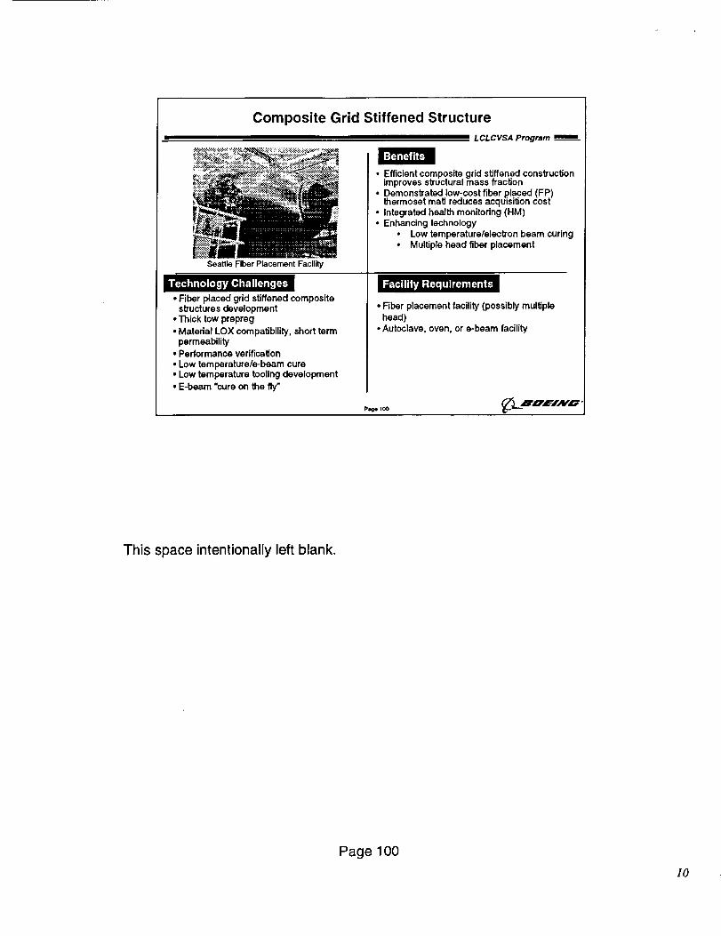
Composite Grid Stiffened Structure
LCLCVSA Program
_._.i__::_:[_:'''.::r!:i.._.:__!i!iiii:i:_::___.!:7%':''''::_'!..,.-_!:-._:_ " ::.
Seattle Fiber Placement Facility
Benefits
i F:PhI,[.]r.z.},=,__.=_,H_-=• Fiber placed grid stiffened composite
structures development
• Thick tow prepreg
• Material LOX compatibility, short term
permeability
• Performance verification
• Low temperature/e-beam cure• Low temperature tooling development
• E-beam "cure on the fly"
• Efficient composite grid stiffened consbuctionimproves structural mass fraction
• ..Demonstrated,low;cost fiber placed (FP)mermose_ mag reauces acquisition cost
• Integrated health monitoring (HM)
• Enhancing technology
• Low temperature/alectron beam curing
• Multiple head fiber placement
• Fiber placement facility (possibly multiple
head)
• Autoclave, oven, or e-beam facility
This space intentionally left blank.
Page 100
]0
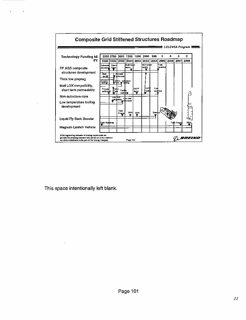
Composite Grid Stiffened Structures Roadmap
LCLCVSA Program i=
Technology Funding k$ 2000 2750 2000 1500 1500 2000 500
FY 1998119,91200O2001=00220032004Sulb.¢a/_ O_¢ Mul_ MLV-I<, _e
FP AGS composite ,_¢_,_ , T_k _*v f"_•
structures development .. _
Thick tow prepreg T._ ,k"°•.V"_U_
Matl LOX compatibility, i
shortterm permeability Pro¢. h o _OTF jCOtOp_'_Iz _ ; Facil _V dlmo • facl
Non-autoclave cure _o. o= _,.co.,
Low temperature tooling _. =u_,,_ _oto_=
development
Uquid Fly-Back Booster
Magnum Launch Vehicle
Tech
Fr_e PDR• con•
¢hR_ Imlzp
Page tot
0 o o 0
2005 2006 2007 2008
Fu_ly
FuJl
qu_ liod
DeI_T ry_
I IPDR
This space intentionally left blank.
Page 101
1]
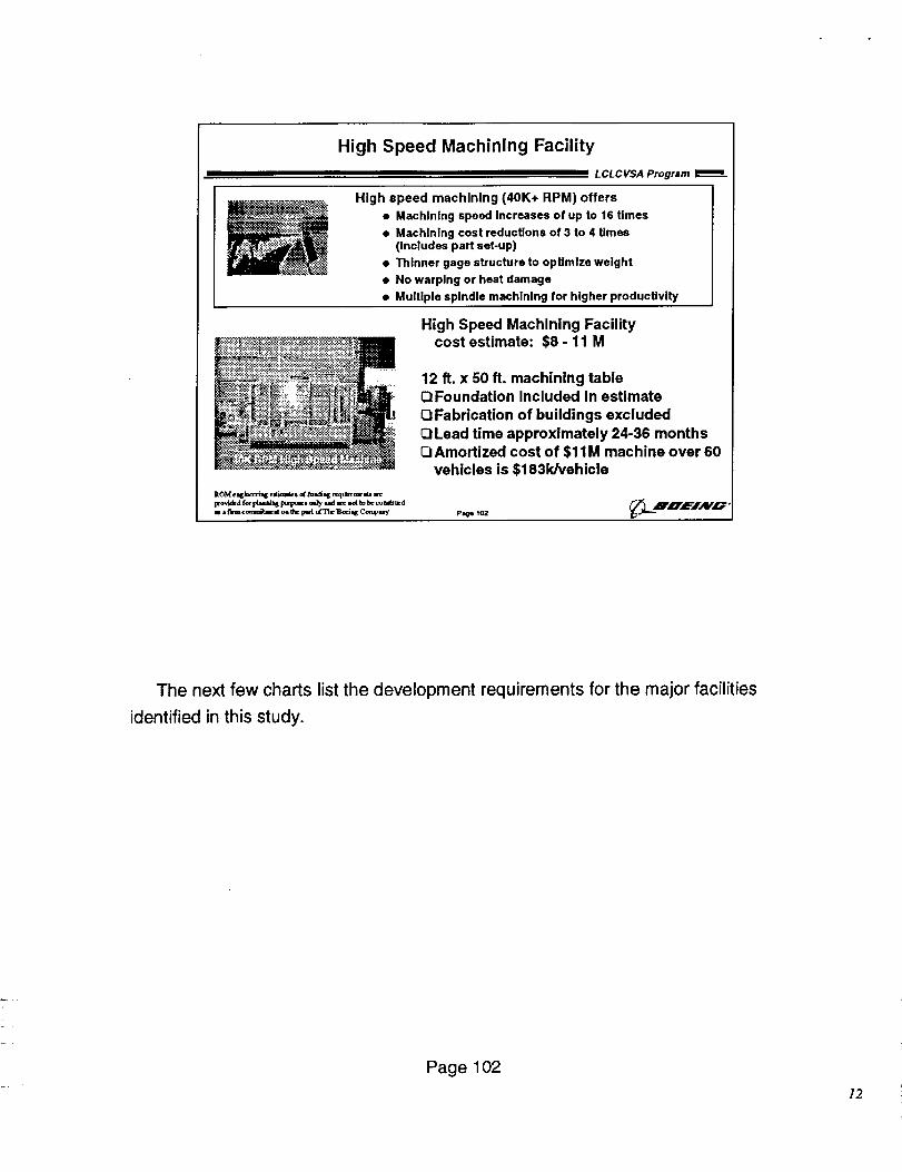
High Speed Machining Facility
L CL C VSA Program
High speed machining (40K+ RPM) offers
• Machining speed Increases of up to 16 times
• Machining cost reducUon$ of 3 to 4 Umes(Includes part set-up)
• Thinner gage structure to optimize weight
• No warping or heat damage
• Multiple spindle machining for higher producUvlty
_,.:.:.::_.!:'::_:!:::_-::-_:::::::_:::::::_::::,-::::;:__:::::._, :>..
I_OMeqC_ed__m_ _u-_ requ_rmK_an_
m__¢mcommitrm-_o_I_ _t _r_ ]B_iq_Cemp_
High Speed Machining Facilitycost estimate: $8 - 11 M
12 ft. x 50 ft. machining table
Foundation included in estimate
Q Fabrication of buildings excluded
_Lead time approximately 24-36 monthsQAmortized cost of $11M machine over 60
vehicles is $183k/vehicle
Page102
The next few charts list the development requirements for the major facilities
identified in this study.
Page 102
]2
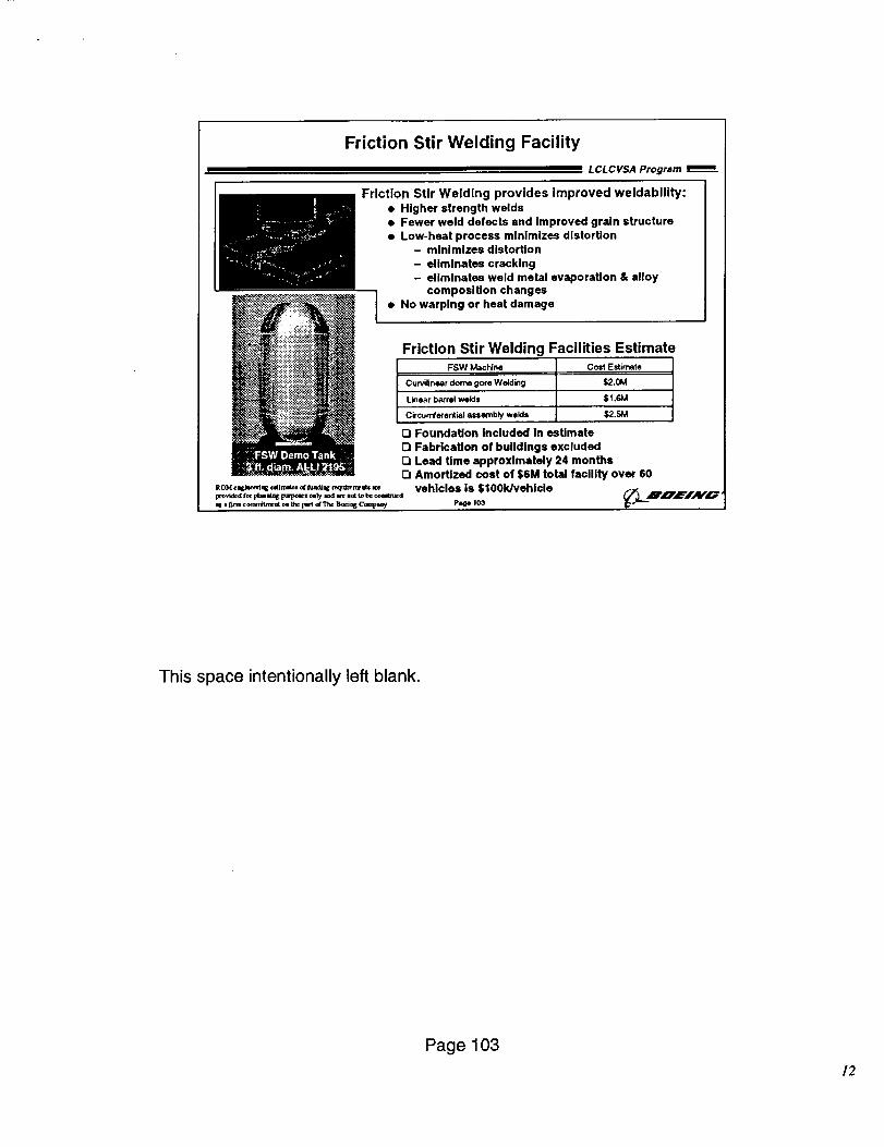
Friction Stir Welding Facility
LCLCVSA Program
Friction Stir Welding provides Improved weldabllity:• Higher strength welds
• Fewer weld defects and improved grain structure
• Low-heat process minimizes distortion
- minimizes distortion
- eliminates cracking
- eliminates weld metal evaporation & alloy
composition changes
• No warping or heat damage
Friction Stir Welding Facilities Estimate
FSW Machine CostEstimate
Cun_ilineardome gore Welding $2.0M
Linear barrelwelds $1.6M
Circumferentialassembly welds $2.5M
Q Foundation Included In estimate
O Fabrication of buildings excluded
Lead time approximately 24 months
Q Amortized cost of $6M total tacllity over 60
vehicles Is $100Wvehicle_=o. ,o_ (- L'.-_B'_'_'iAy_"
This space intentionally left blank.
Page 103
12
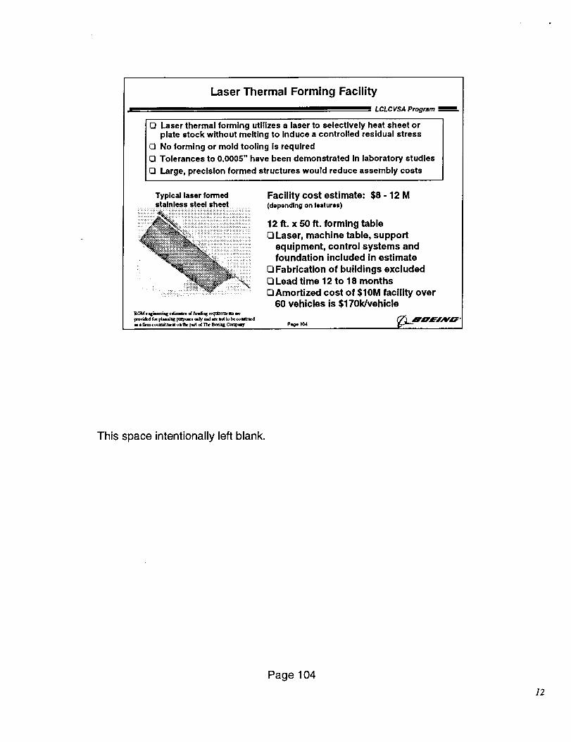
Laser Thermal Forming Facility
i i=lm LCLCVSA Program _.
Q Laser thermal forming utilizes a laser to selectively heat sheet orplate stock without melting to Induce a controlled residual stress
Ell No forming or mold tooling is required
Q Tolerances to 0.0005" have been demonstrated In laboratory studies
Q Large, precision formed structures would reduce assembly costs
Typical laser formedstainless steel sheet
i iiiiiiiii
Facility cost estimate: $8 - 12 M(depending on features)
12 ft. x 50 ft. forming tableQLaser, machine table, support
equipment, control systems andfoundation included in estimate
Q Fabrication of buildings excludedQLead time 12 to 18 monthsQAmortized cost of $10M facility over
60 vehicles is $1701dvehicle
This space intentionally left blank.
Page 104
]2
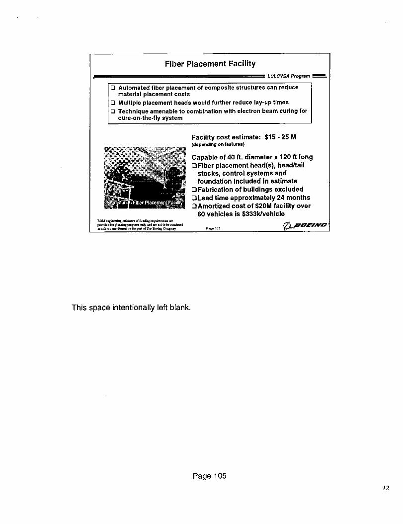
Fiber Placement Facility
LCLCVSA Program mm
I Q Automated fiber placement of composite structures can reduce
material placement costs[3 Multiple placement heads would further reduce lay-up times0 Technique amenable to combination with electron beam curing for
cure-on-the-fly system
ROMe q_aeed_ _r_t_ afl_ req_-e_ _.s
Ixovi_d r¢¢ piaaai_ purp_el ealyad are ietrobe confined
as a_rm caram_ae_ os the p_rt_The I_ei_ C_any
Facility cost estimate: $15 - 25 M(depending on features)
Capable of 40 ft. diameter x 120 ft longEIFiber placement head(s), head/tail
stocks, control systems andfoundation included in estimateFabrication of buildings excluded
_Lead time approximately 24 monthsCIAmortized cost of $20M facility over
60 vehicles is $333k/vehicle
This space intentionally left blank.
Page 105
/2
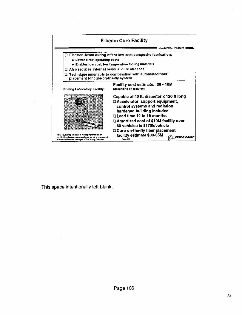
E-beam Cure Facility
LCLCVSA Program
O Electron-beam curing offers low-cost composite fabrication:
• Lower direct operating costs
• Enables low cost, low temperature tooling materials
Ell Also reduces Internal residual cure stresses
Q Technique amenable to combination with automated fiber
placement for cure-on-the-fly system
Boeing Laboratory Facility:
:_:;':!£_::_:::._._.._:_ .:;.'-:.:.:.:..:::._:-:::"
Facility cost estimate: $8 - 10M(depending on features)
Capable of 40 ft. diameter x 120 ft long
O Accelerator, support equipment,
control systems and radiation
hardened building includedOLead time 12 to 18 months
OAmortized cost of $10M facility over60 vehicles is $1701dvehicle
EllCure-on-the-fly fiber placement
facility estimate $30-35M A,_LB_,,L=.i,_,_.Page 10(5
This space intentionally left blank.
Page 106
]2
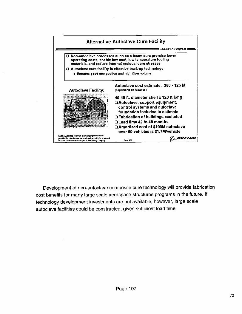
Alternative Autoclave Cure Facility
L CL C VSA Program
Eli Non-autoclave processes such as e-beam cure promise loweroperating costs, enable low cost, low temperature toolingmaterials, and reduce internal residual cure stresses
Q Autoclave cure facility Is effective back-up technology
• Ensures good compaction and high fiber volume
Autoclave Facility:
i_ii_ii_i:_:_:':!i_:::,-........ :
Autoclave cost estimate: $80 - 125 M
(depending on features)
40-45 ft. diameter shell x 120 ft long
QAutoclave, support equipment,
control systems and autoclavefoundation Included in estimate
El Fabrication of buildings excludedEILead time 42 to 48 months
QAmortized cost of $100M autoclaveover 60 vehicles is $1.7M/vehicle
P,_ ,07 _'_.-L'-_'E'I/¥O'
Development of non-autoclave composite cure technology will provide fabrication
cost benefits for many large scale aerospace structures programs in the future. If
technology development investments are not available, however, large scale
autoclave facilities could be constructed, given sufficient lead time.
Page 107
]2
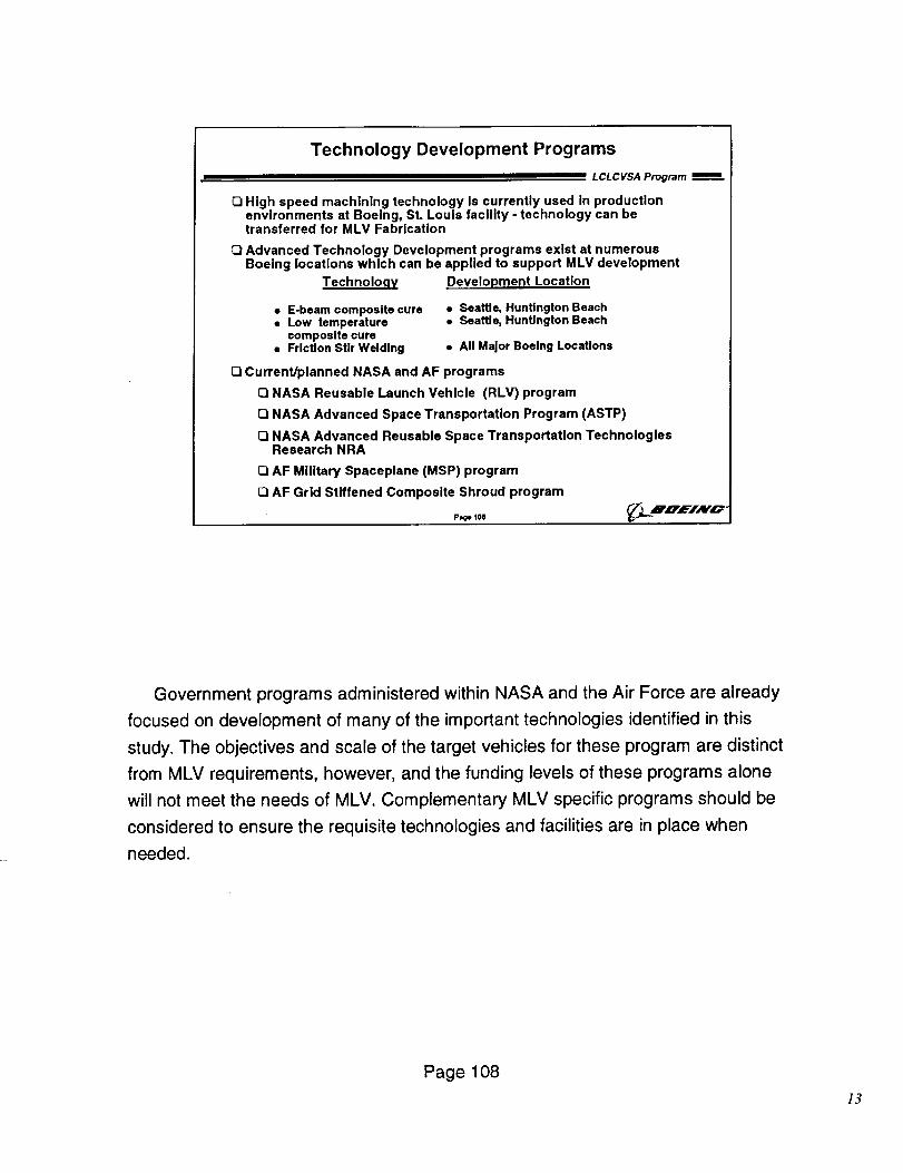
Technology Development Programs
LCLCVSA Program
O High speed machining technology Is currently used in productionenvironments at Boeing, St. Louis facility - technology can betransferred for MLV Fabrication
O Advanced Technology Development programs exist at numerousBoeing locations which can be applied to support MLV development
Technolo.qy .Development Location
• E-beam composite cure • Seattle, Huntington Beach• Low temperature • Seattle, Huntington Beach
composite cure• Friction Stir Welding • All Major Boeing Locations
EliCurrent/planned NASA and AF programs
O NASA Reusable Launch Vehicle (RLV) program
O NASA Advanced Space Transportation Program (ASTP)
OI NASA Advanced Reusable Space Transportation TechnologiesResearch NRA
OI AF Military Spaceplane (MSP) program
OAF Grid Stiffened Composite Shroud program
P_, 1o8 _. L-4B'va'E'I'Av'O'
Government programs administered within NASA and the Air Force are already
focused on development of many of the important technologies identified in this
study. The objectives and scale of the target vehicles for these program are distinct
from MLV requirements, however, and the funding levels of these programs alone
will not meet the needs of MLV. Complementary MLV specific programs should be
considered to ensure the requisite technologies and facilities are in place when
needed.
Page 108
13
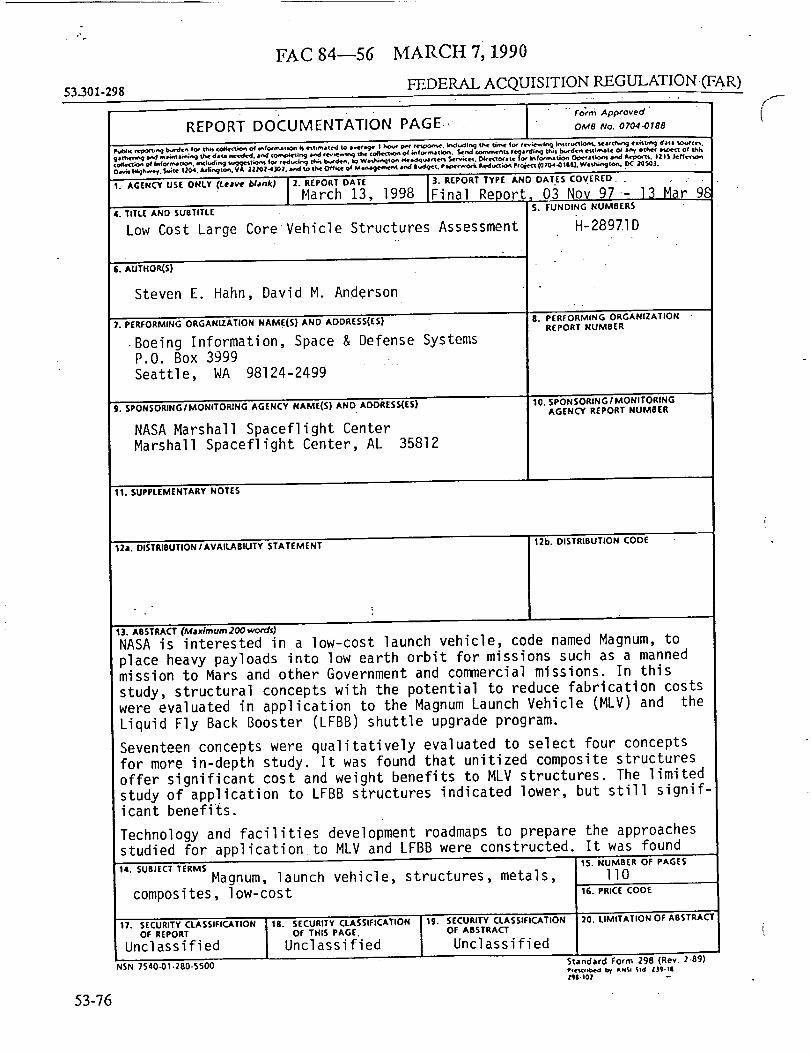
"'r
MARCH 7; 1990
53301-298 FEDERAL ACQUISITION REGULATION(FAR )
FAC 84--56
If
53-76
OMI I_wQlt, _t& 1204. A¢llrl_ |0_, VA l_l 4 _ i_. N tO |M Off'it O+ M Ift_l('ffiCnl _ IIud_'q., P IIM't_Oclt gt'd tKliO_ P TOIOi't {0 |04_ I |Ill. Wl f_¢l_ tit, f% 0( _0el0].
!. AGENCY USE ONLY (Lea_e blank) 2. REPORT DATE ]. REPORT TYPE AND DATES COVERED.. --
March 13, 1998 Final Report, 03 Nov 97- 13 Mar 9_4. TITLE AND SUBTITLE S. FUNDING NUMBERS --
Low Cost Large Core Vehicle Structures Assessment H-28971D
Ii. AUTHOR(S)
Steven E. Hahn, David M. Anderson
7. PERFORMING ORGANIZATION NAME(S) AND ADDRESSEES)
•Boeing Information, Space & Defense SystemsP.O. Box 3999
Seattle, WA 98124-2499
9. SPONSORING/MONITORING AGENCY NAME(S} ANO AOORESS(ES}
NASA Marshall Spaceflight CenterMarshall Spaceflight Center, AL 35812
8. PERFORMING ORGANIZATION
REPORT NUMBER
10. SPONSORING IMONITORING
AGENCY REPORT NUMBER
11. SUPPLEMENTARY NOTES
12a. DISTRIBUTION/AVAILABILITY STATEMENT 12b. DISTRIBUTION CODE
13. ABSTRACT (Max�mum 2_ words)
NASA is interested in a low-cost launch vehicle, code named Magnum, toplace heavy payloads into low earth orbit for missions such as a manned
mission to Mars and other Government and commercial missions. In this
study, structural concepts with the potential to reduce fabrication costswere evaluated in application to the Magnum Launch Vehicle (MLV) and the
Liquid Fly Back Booster (LFBB) shuttle upgrade program.
Seventeen concepts were qualitatively evaluated to select four concepts
for more in-depth study. It was found that unitized composite structures
offer significant cost and weight benefits to MLV structures. The limited
study of application to LFBB structures indicated lower, but still signif-icant benefits.
Technology and facilities development roadmaps to prepare the approachesstudied for application to MLV and LFBB were constructed. It was found
14. SUBJECT TERMS
Magnum, launch vehicle, structures, metals,composites, low-cost
17. SECURITY CLASSIFICATION 18. SECURITY CLASSIFICATIONOF REPORT OF THIS PAGE.
Unclassified Unclassified
NSN 7S40-01-280-$500
15. NUI_tBER OF PAGES
llO16. PRICE COOE
19. SECURITY CLASSIFICATION iO. LIMITATION OF ABSTRACT
OF ABSTRACT
Unclassified
Standacd Form 298 (Rev 2-B?)
Z$(Lt02
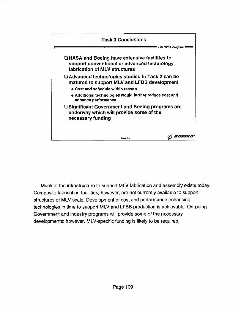
Task 3 Conclusions
LCLCVSA Program _=
O NASA and Boeing have extensive facilities to
support conventional or advanced technologyfabrication of MLV structures
[] Advanced technologies studied in Task 2 can be
matured to support MLV and LFBB development
• Cost and schedule within reason
• Additional technologies would further reduce cost andenhance performance
[] Significant Government and Boeing programs are
underway which will provide some of the
necessary funding
Much of the infrastructure to support MLV fabrication and assembly exists today.
Composite fabrication facilities, however, are not currently available to support
structures of MLV scale. Development of cost and performance enhancing
technologies in time to support MLV and LFBB production is achievable. On-going
Government and industry programs will provide some of the necessary
developments; however, MLV-specific funding is likely to be required.
Page 109
that the cost and schedule to develop these approaches were in line withboth MLV and LFBB development schedules. Current Government and Boeingprograms which address elements of the development of the technologiesidentified are underway. It is recommended that NASA devote resourcesin a timely fashion to address the specific elements related to MLVand LFBB structures.

I