low-cost and portable uv holographic microscope for high … · 2019-03-02 · distinguish protein...
TRANSCRIPT
APL Photonics ARTICLE scitation.org/journal/app
Low-cost and portable UV holographicmicroscope for high-contrast proteincrystal imaging
Cite as: APL Photon. 4, 030804 (2019); doi: 10.1063/1.5080158Submitted: 6 November 2018 • Accepted: 31 January 2019 •Published Online: 1 March 2019
Mustafa Ugur Daloglu,1,2,3,a) Aniruddha Ray,1,2,3,b) Michael J. Collazo,4,5,6,7,8,c) Calvin Brown,1,2,3,d) Derek Tseng,1,2,3,e)
Blanca Chocarro-Ruiz,9,f) Laura M. Lechuga,9,g) Duilio Cascio,4,5,6,7,8,h) and Aydogan Ozcan1,2,3,10,i)
AFFILIATIONS1Electrical and Computer Engineering Department, University of California, Los Angeles, California 90095, USA2Bioengineering Department, University of California, Los Angeles, California 90095, USA3California NanoSystems Institute (CNSI), University of California, Los Angeles, California 90095, USA4Howard Hughes Medical Institute, University of California, Los Angeles, California 90024, USA5Department of Energy Institute, University of California, Los Angeles, California 90024, USA6Biological Chemistry Department, University of California, Los Angeles, California 90024, USA7Chemistry and Biochemistry Department, University of California, Los Angeles, California 90024, USA8Molecular Biology Institute, University of California, Los Angeles, California 90024, USA9Catalan Institute of Nanoscience and Nanotechnology (ICN2), CSIC, BIST, and CIBER-BBN, Campus UAB, Bellaterra,08193 Barcelona, Spain
10Department of Surgery, David Geffen School of Medicine, University of California, Engr. IV 68-119, 420 Westwood Plaza,Los Angeles, California 90095, USA
Note: This paper is part of an APL Photonics Special Topic on Computational Optical Imaging.a)[email protected])[email protected])[email protected])[email protected])[email protected])[email protected])[email protected])[email protected])Author to whom correspondence should be addressed: [email protected]. Tel.: +1(310)825-0915. Fax: +1(310)206-4685.
ABSTRACTImaging protein crystals and distinguishing them from salt crystals is an important task for protein crystallographers. Theconventional tool used for this purpose is a dual-mode microscope composed of bright-field and ultraviolet (UV) induced fluo-rescence modes. The distinction between a protein and a salt crystal is made based upon the fluorescence response to the UVexcitation, where most protein crystals absorb the UV excitation and emit fluorescence, unlike salt crystals. These dual-modeoptical microscopes are sensitive; however, they are relatively bulky and expensive as they require UV-grade optics. As an alter-native, here we demonstrate that on-chip UV holographic imaging offers a low-cost, portable, and robust technique to image anddistinguish protein crystals from salt crystals, without the need for any expensive and bulky optical components. Only composedof a UV light-emitting-diode at 280 nm and a consumer-grade complementary metal–oxide–semiconductor image sensor de-capped and interfaced to a Raspberry Pi single-board computer, the necessary information from the crystal samples (placed veryclose to the sensor active area) is captured in the form of in-line holograms and extracted through digital back-propagation. Inthese holographic amplitude reconstructions, protein crystals appear significantly darker compared to the background due to the
APL Photon. 4, 030804 (2019); doi: 10.1063/1.5080158 4, 030804-1
© Author(s) 2019
APL Photonics ARTICLE scitation.org/journal/app
strong UV absorption, unlike salt crystals which do not show any contrast, enabling us to clearly distinguish between them. Webelieve that the on-chip UV holographic microscope could serve as a low-cost, sensitive, and robust alternative to conventionallens-based UV-microscopes used in protein crystallography.
© 2019 Author(s). All article content, except where otherwise noted, is licensed under a Creative Commons Attribution (CC BY) license(http://creativecommons.org/licenses/by/4.0/). https://doi.org/10.1063/1.5080158
I. INTRODUCTION
Protein crystallographers rely on a dual-mode opticalmicroscope composed of bright-field and ultraviolet (UV)induced fluorescence modes to image protein crystals as wellas to distinguish them from salt crystals that could form dur-ing the crystallization process. This distinction is mainly basedon the response to the UV illumination, where most proteincrystals absorb the UV light and emit fluorescence throughtryptophan residues, unlike most salt crystals.1,2 In additionto UV fluorescence,3,4 the strong absorption of UV light withinorganic materials5,6 has been utilized as an inherent contrastagent in imaging tissue samples,7 cells,8 intracellular nucleicacids and proteins,9–12 viruses,13 and protein aggregates,14making UV microscopy15 an important tool for researchers.However, conventional lens-based UV microscopy is a rela-tively expensive imaging modality, requiring the use of rel-atively bulky optical components that are specially designedfor UV wavelengths, in addition to UV light sources and UV-sensitive cameras for bright-field imaging,2 adding up to sig-nificant costs (e.g., $35k-200k).16 Furthermore, inherent lim-itations of lens-based microscopy also apply to conventionalUV microscopes, where the trade-off between the field-of-view (FOV) and resolution limits the total sample area that canbe imaged.
As an alternative, on-chip holographic imaging17–20 offersa cost-effective option21–24 for such microscopy tasks without
the need for imaging lenses or other bulky optical compo-nents, only using consumer-grade image sensor chips25 andsimple light sources like light-emitting diodes (LEDs) open-ing up new frontiers for portability.26–29 The ever decreasingpeak emission wavelengths and increasing efficiencies of LEDtechnologies made the deep UV LEDs (240 nm-360 nm)30–33more available and affordable. This, when integrated with thecapabilities of portable and cost-effective on-chip holographicmicroscopy tools, enables a wide range of studies related toproteins, particularly in the field of crystallography.
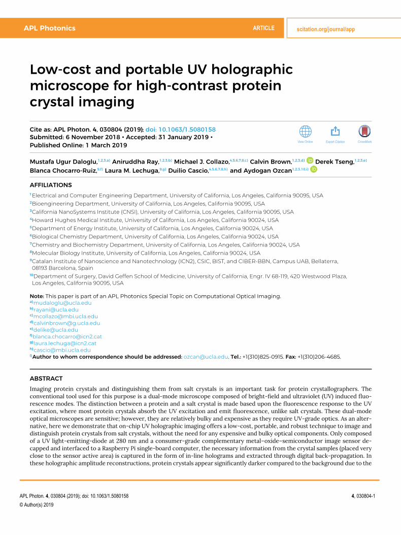
Here we present a portable on-chip holographic imag-ing platform (Fig. 1) that is composed of a UV-LED operat-ing at 280 nm peak wavelength and a de-capped comple-mentary metal–oxide–semiconductor (CMOS) image sensorconnected to a Raspberry Pi single-board computer.34,35 Thesample is placed very close (∼300-400 µm) to the image sen-sor and the light source further above, where the interferencebetween the light scattered from the target crystals and thebackground illumination creates in-line holograms that aredigitized/recorded by using the image sensor. The capturedframes are then digitally processed to extract the informa-tion about the target objects that is encoded in the holograms,resulting in UV transmission images over a large FOV that isonly limited by the sensor active area (>10 mm2).
The utility of this platform in crystallography was demon-strated by imaging different protein crystals including pro-teinase K (Figs. 2 and 3), the RING1B complex (Fig. 4), maltose
FIG. 1. (a) Our portable holographicon-chip imaging platform operates at280 nm illumination wavelength. The UVLED is spectrally filtered using a band-pass filter to block the side-bands, let-ting through pure UV light with 280 nmpeak wavelength and a 10 nm band-width toward the sample, which is placedvery close to the image sensor (∼300-400 µm), utilizing the full active area asthe imaging FOV (>10 mm2). (b) A sim-plified CAD model of the same portableon-chip imaging platform.
APL Photon. 4, 030804 (2019); doi: 10.1063/1.5080158 4, 030804-2
© Author(s) 2019
APL Photonics ARTICLE scitation.org/journal/app
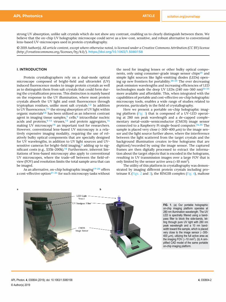
FIG. 2. Using the setup shown in Fig. 1,proteinase K crystals appear significantlydarker compared to the background leveldue to the strong UV absorption at280 nm, unlike salt crystals. (a) Bright-field microscope images of proteinaseK, sodium chloride, and ammonium sul-fate crystals. (b) Amplitude reconstruc-tions of the same FOVs in (a), proteinaseK crystals appearing significantly darker.(c) X-ray diffraction data from the pro-teinase K, sodium chloride, and ammo-nium sulfate crystal samples, with largestspacing values of 30 Å, 3.25 Å, and3.25 Å, respectively.
binding protein (Fig. 4), and salt crystal samples which includesodium chloride (Fig. 2), ammonium sulfate (Fig. 2), lithiumacetate (Fig. 3), and lithium sulfate (Fig. 3). Our mobile holo-graphic platform can clearly differentiate between proteincrystals and salt crystals due to the strong contrast in theprotein crystal images which appear significantly darker com-pared to the background. Without the need for fine align-ment and temperature stability, unlike its lens-based counter-parts, this platform would be a low-cost, robust, and portablealternative to conventional UV microscopes used by proteincrystallographers.
II. RESULTS AND DISCUSSIONOur portable on-chip imaging platform (Fig. 1) is built
upon the versatile Raspberry Pi 3 board,35 with its readilyavailable 8 Megapixel CMOS camera, all housed within a cus-tom designed and 3D printed shell which also holds a UV LEDoperating at 280 nm peak wavelength with a band-pass filterto block the side-band emissions.31,32,36 The CMOS camerais de-capped, removing the lens module, and the sample isplaced very close (∼300-400 µm) to the active area of theimage sensor chip that is fully utilized as the imaging FOV[>10 mm2, Fig. 3(a)]. The filtered UV light is scattered throughthe sample, generating in-line holograms through its interfer-ence with the background light that is captured by using the
image sensor. These holographic images are then digitally pro-cessed to extract the amplitude information encoded in theinterference patterns from the target objects.
We tested our portable on-chip imaging platform to verifythe effect of strong UV absorption in our amplitude recon-structions, imaging protein crystals (Fig. 2). Samples were pre-pared by constructing imaging chambers using UV fused silicaglass slides and pieces of ACLAR protein crystallization covers,a standard material used by protein crystallographers whichis also UV transparent. It is important to note that additionalconsideration has to be given in the transparency of mate-rials for coherent imaging modalities like holography, as theirregularities in the material volume could result in strongbackground distortions. The standard UV transparent ACLARused by protein crystallographers is suitable for holographicimaging, only creating a faint modulation in the background[Fig. 2(b)] which does not affect our imaging quality.
Our imaging platform (Fig. 1) was first tested by prepar-ing a sample with proteinase K, a serine protease readilyavailable for crystallization, which contains aromatic aminoacids that fluoresce when excited at 280 nm light, and twosalt crystal samples (sodium chloride and ammonium sulfate)[Figs. 2(a) and 2(b)], where the respective X-ray diffractiondata are shown in Fig. 2(c). Individual crystals were pipettedalong with ∼1 µl of solution onto the ACLAR piece (sticky sidefacing up), and a UV fused silica was used to seal the droplet
APL Photon. 4, 030804 (2019); doi: 10.1063/1.5080158 4, 030804-3
© Author(s) 2019
APL Photonics ARTICLE scitation.org/journal/app
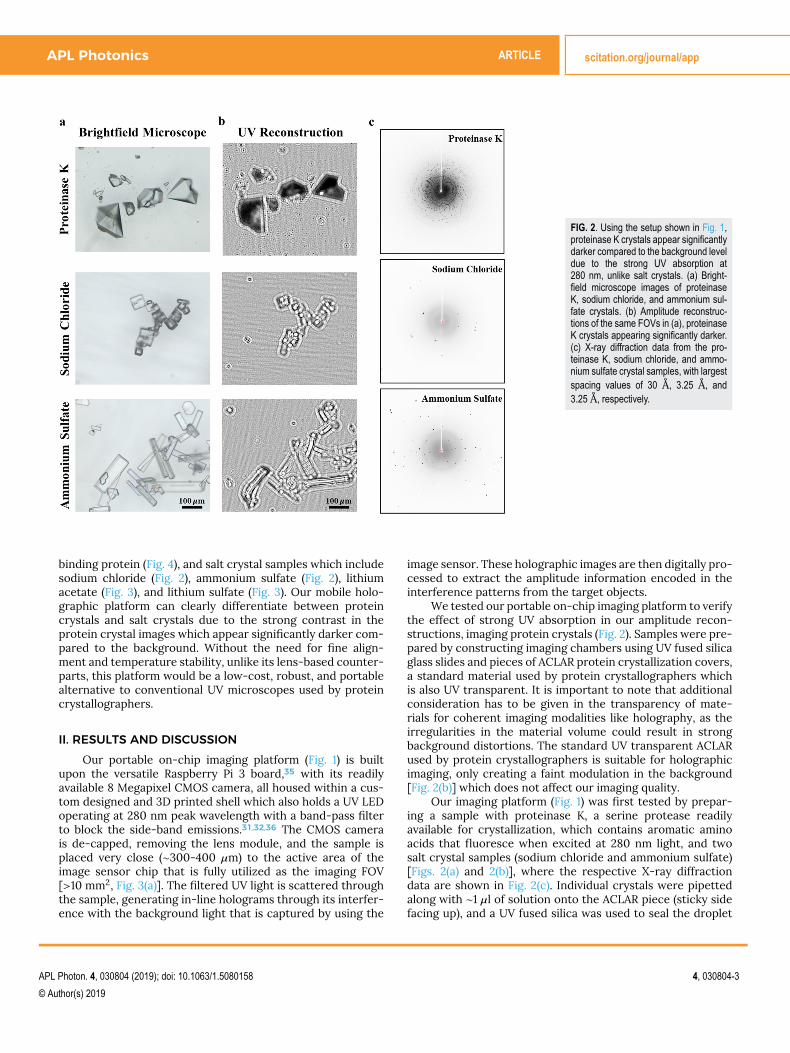
FIG. 3. A low-cost, portable, and high-throughput alternative to lens-based UV microscopes used by protein crystallographers to distinguish between protein and salt crystals.(a) The full FOV (>10 mm2) image captured by our on-chip microscopy platform (Fig. 1) where the red rectangle shows a typical FOV possible using a lens-based UVmicroscope with a 5× objective lens. (b) Samples containing proteinase K and salt crystals (lithium acetate and lithium sulfate) in the same chamber, imaged by using thelens-based UV microscope in both brightfield and UV fluorescence modes. The proteinase K crystals strongly absorb the 280 nm UV light and emit fluorescence, where thesalt crystals do not. (c) Protein crystals show a significantly stronger contrast compared to salt crystals (p < 0.02). The standard deviation bars represent the variation ofthe contrast within the rectangular regions used to calculate the average contrast of the target objects. (d) The amplitude reconstructions of the same FOVs captured by ouron-chip UV imaging platform. The same crystals that emitted fluorescence in (b) appear significantly darker compared to the background due to the stronger absorption, whilethe crystals that did not emit fluorescence do not show statistically significant contrast in our amplitude reconstructions.
into the chamber. The amplitude reconstructions of our holo-grams clearly show that the protein crystals appear muchdarker compared to the background, unlike the salt crys-tals [Fig. 2(b)]. The amplitude reconstruction results shownin Fig. 2(b) could be further improved using various phase-retrieval techniques17 to mitigate twin-image artifacts, at thecost of additional computation and/or holographic measure-ments.
To further evaluate our portable on-chip holographicimaging platform, we imaged mixed-samples containing bothprotein (proteinase K) and salt crystals (lithium acetate andlithium sulfate) within the same FOV [Figs. 3(a), 3(b), and 3(d)],prepared by sandwiching droplets of ∼1 µl buffer solutioncontaining the crystals between a UV fused silica slide anda piece of ACLAR sheet. The crystals were grown in theirrespective buffer solutions and then individually fished by amicroloop and deposited in the droplet before sealing. Thesamples were first imaged with the lens-based microscope,which is able to distinguish between the protein and thesalt crystal through the fluorescence of the protein crystal[Fig. 3(b)], where the protein crystal is observed to be emittingfluorescence, while the salt crystal remains dark. The sam-ples were then imaged with our on-chip microscopy platform[Figs. 3(a) and 3(d)], where the proteinase K crystals showed a
significantly stronger contrast (p < 0.02) compared to thesalt crystals [Fig. 3(c)]. We calculated the contrast (C) inour UV holographic amplitude reconstructions by subtract-ing the average amplitude signal of the target crystals (Sc)from the average background signal value (Sb) and dividing thisdifference by the average background signal value,14,37 i.e.,
C =Sb − Sc
Sb, (1)
where Sc is calculated within the largest rectangular regionthat fits inside the target crystal and Sb is calculated within aclear region of the FOV that does not contain any objects.
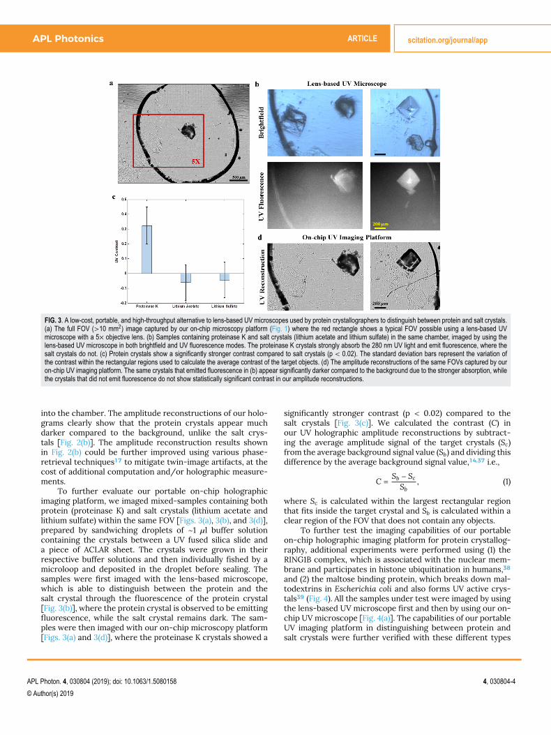
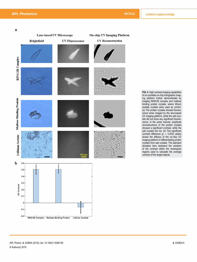
To further test the imaging capabilities of our portableon-chip holographic imaging platform for protein crystallog-raphy, additional experiments were performed using (1) theRING1B complex, which is associated with the nuclear mem-brane and participates in histone ubiquitination in humans,38and (2) the maltose binding protein, which breaks down mal-todextrins in Escherichia coli and also forms UV active crys-tals39 (Fig. 4). All the samples under test were imaged by usingthe lens-based UV microscope first and then by using our on-chip UV microscope [Fig. 4(a)]. The capabilities of our portableUV imaging platform in distinguishing between protein andsalt crystals were further verified with these different types
APL Photon. 4, 030804 (2019); doi: 10.1063/1.5080158 4, 030804-4
© Author(s) 2019
APL Photonics ARTICLE scitation.org/journal/app
FIG. 4. High contrast imaging capabilitiesof our portable on-chip holographic imag-ing platform further demonstrated byimaging RING1B complex and maltosebinding protein crystals, where lithiumacetate crystals were used as control.(a) The protein crystals showed fluores-cence when imaged by the lens-basedUV imaging platform, while the salt crys-tals did not show any significant fluores-cence. In the same manner, amplitudereconstructions of the protein crystalsshowed a significant contrast, while thesalt crystals did not. (b) This significantcontrast difference (p < 0.003) clearlyshows the efficacy of the on-chip UVimaging platform in differentiating proteincrystals from salt crystals. The standarddeviation bars represent the variationof the contrast within the rectangularregions used to calculate the averagecontrast of the target objects.
APL Photon. 4, 030804 (2019); doi: 10.1063/1.5080158 4, 030804-5
© Author(s) 2019

APL Photonics ARTICLE scitation.org/journal/app
of proteins, which showed a significantly higher contrast(p < 0.003) compared to salt crystals [Fig. 4(b)].
In summary, recent improvements in UV LED technolo-gies have made deep UV LEDs with short peak emission wave-lengths and improved efficiencies more accessible, enablingthe design of a portable and low-cost on-chip UV imag-ing platform as a potential alternative to the expensive andbulky dual-mode UV microscopes used by protein crystallog-raphers. We expect that our portable on-chip UV holographicimaging platform could be even further strengthened withnear real-time imaging capabilities, driven by future improve-ments in deep UV LED power output efficiencies, enablingthe use of lower sensor integration times and the increasingavailability of embedded graphics processing units (GPUs) forsingle-board computers.
III. MATERIALS AND METHODSA. UV on-chip imaging platform
Our portable on-chip microscopy platform (Fig. 1) is com-posed of a de-capped 8 Mega-pixel (3280 horizontal × 2464vertical, with an active area of ∼10.14 mm2), 1.12 µm pixelpitch, CMOS image sensor (IMX219, Sony Corporation, Tokyo,Japan) interfaced to a Raspberry Pi 3B single-board computer,a deep UV LED operating at 280 nm peak wavelength (TH-UV280J9-C-H-B, Tianhui Optoelectronics Co., Ltd, Guang-dong Province, China), and a UV band-pass filter with acenter wavelength of 280 nm and a bandwidth of 10 nm (FF01-280/10-25, Semrock, NY, USA) to block the side-band emis-sions31,32,36 from the UV LED. All of these components arehoused within a custom designed and 3D printed acrylonitrilebutadiene styrene (ABS) (Stratasys, Dimension Elite) shell. Acustom Python script was used to capture, extract, and savethe raw frames/holograms from the sensor to the onboardstorage of the Raspberry Pi 3B.
B. Data processingSince the green pixels of the image sensor were most
responsive to the UV illumination,14 the values in the redand blue pixels of the raw frames were replaced withthe average of their neighboring green pixels. The framescontaining holographic projections were then digitally back-propagated using the angular spectrum approach,40 numeri-cally solving the Rayleigh-Sommerfeld integral by multiplyingthe Fourier transform of the hologram with the transferfunction of wave propagation,17,26 generating the amplitudeimages of the sample. The complete data processing takes∼1 minute using a standard desktop computer (Dell Optiplex9010, Intel i7, 32 GB RAM) operating MATLAB (MathWorks, MI,USA).
The statistical significance of the increased contrast inthe amplitude reconstructions of protein crystals comparedto salt crystals was verified using a t-test41 with two sepa-rate experiments for proteinase K [Fig. 3(d)] and three sep-arate experiments for the additional set of proteins whichincluded the RING1B complex and the maltose binding protein[Fig. 4(a)].
C. Sample preparationUV compatible materials which include UV fused silica
slides (10 mm × 10 mm, 0.2 mm thick, MTI Corp., CA, USA)and pieces of standard protein crystallization covers madeof ACLAR composed of poly-chloro-trifluoroethylene (GraceBio-Labs ProCrystal Cover 875238, OR, USA) were used to con-struct the sample chambers holding the crystal samples. A0.8-1 µl droplet containing the crystals and the correspondingbuffer solution was deposited onto an ACLAR piece containingone well, sticky side facing up. A UV fused silica slide was thengently used to cover the well, sealing the droplet. It is note-worthy that the ACLAR standard protein crystallization covermaterial was suitable for coherent imaging and only resulted ina faint background modulation [Fig. 2(b)] which did not affectour imaging quality.
D. Protein and salt crystallizationA TTP LabTech mosquito (TTP Labtech, Inc., MA, USA) was
used to generate 96-well hanging drop crystallization setups.All protein crystals were grown in a manner of days usingvapor diffusion. Proteinase K (VWR catalog number 97062-238, PA, USA) was crystallized by dissolving lyophilized pow-der in water to obtain a 50 mg/ml stock. The stock solu-tion was mixed 1:1 with 1.5 M ammonium sulfate and 0.1 MTris-HCl pH 7.5. Maltose binding protein 80 mg/ml in 20 mMTris–HCl pH 8.0 and 50 mM NaCl was crystallized by mix-ing 1:1 with 0.2M magnesium chloride hexahydrate, 0.1M4-Morpholineethanesulfonic acid pH 6.0%, and 20% w/vPolyethylene glycol 6000. Oligomerization regions of RING1B,polycomb group RING finger protein 4, chromobox 8, andpolyhomeotic homolog 1 were supplied by the Chemistry andBiochemistry Department at UCLA. This sample was mixed1:1 with 0.7M sodium formate pH 7.0% and 20% w/v PEG3350. All 300 nl drops were equilibrated over 100 µl of thecorresponding crystallization solutions.
1.0M sodium chloride, 2.0M ammonium sulfate, 1.0Mlithium acetate, and 1.0 lithium sulfate were dispensed in µlaliquots and allowed to evaporate in air while being observedin a stereomicroscope. Crystals that formed by dehydrationin aqueous solution were manually harvested using 50 µmmicroloops (Mitegen M5-L18SP-50LD, NY, USA) and placed in1 µl of the stock salt solution. These solutions, containing crys-tals, were placed on the ACLAR surface by using a pipette forimaging.
E. Lens-based UV microscopyA dual-mode UV microscope (Korima PRS-1000, CA, USA)
was used for comparison with the holographic imaging plat-form. Samples were imaged with the UV microscope firstand then holographically imaged with our mobile instrument.Crystals were exposed to 280 nm light for no more than 5 s,and the images taken were compared with the correspondingholographic images [Fig. 4(a)].
F. X-ray diffractionTo further distinguish protein crystals from salt, diffrac-
tion images were taken. Individual crystals from the target
APL Photon. 4, 030804 (2019); doi: 10.1063/1.5080158 4, 030804-6
© Author(s) 2019
APL Photonics ARTICLE scitation.org/journal/app
sample were harvested and placed in their mother liquorwith 33% glycol added to resist the formation of crys-talline water. A rotating anode generator (Rigaku FRE+, Tokyo,Japan) and an imaging plate detector (Rigaku HTC, Tokyo,Japan) were employed for X-ray data collection. Macro-molecule crystals are distinguishable from salt crystals bylower resolution reflections that occur as the result oflarger spacing between symmetric elements of the crystal[Fig. 2(c)].
IV. CONCLUSIONSWe designed and built a low-cost and portable on-chip
holographic imaging platform operating at the deep UV wave-length of 280 nm for high-contrast imaging of protein crys-tals. Without the need for sensitive, bulky, and costly compo-nents, our platform offers a low-cost, high-throughput, androbust alternative to the dual-mode optical microscopes com-posed of bright-field and ultraviolet (UV) induced fluorescencemodes that are routinely used by protein crystallographersto image protein crystals and to distinguish them from saltcrystals. We tested the on-chip holographic imaging platformby imaging different protein crystals including proteinase K,maltose binding protein, and the RING1B complex in compar-ison with several different salt crystals which include sodiumchloride, ammonium sulfate, lithium acetate, and lithium sul-fate. While the amplitude reconstructions of the protein crys-tals appear much darker compared to the background, thesalt crystals do not show any contrast, clearly distinguish-ing between the two types of crystals. We believe that ourportable on-chip holographic platform could aid protein crys-tallographers as a low-cost and robust alternative platformto image protein crystals and to distinguish them from saltcrystals.
ACKNOWLEDGMENTSThe Ozcan Research Group at UCLA acknowledges the
support of NSF Engineering Research Center (ERC, PATHS-UP), the Army Research Office (ARO; Nos. W911NF-13-1-0419and W911NF-13-1-0197), the ARO Life Sciences Division, theNational Science Foundation (NSF) CBET Division Biopho-tonics Program, the NSF Emerging Frontiers in Researchand Innovation (EFRI) Award, the NSF INSPIRE Award, NSFPartnerships for Innovation: Building Innovation Capacity(PFI:BIC) Program, the National Institutes of Health (NIH, No.R21EB023115), the Howard Hughes Medical Institute (HHMI),Vodafone Americas Foundation, the Mary Kay Foundation, andthe Steven and Alexandra Cohen Foundation. The authorsacknowledge Zachary Scott Ballard and Yichen Wu for theirhelp in obtaining some of the hardware components. Wethank Isaijah Johnson and Trevor Sobol for their assistancein crystallizing protein samples for evaluation. The UCLA X-ray diffraction facilities are supported by the BER program ofthe Department of Energy Office of Science under Award No.DE-FC02-02ER63421.
A.O. is the co-founder of a company that commercializescomputational imaging and sensing technologies.
REFERENCES1S. Desbois, S. A. Seabrook, and J. Newman, “Some practical guidelines forUV imaging in the protein crystallization laboratory,” Acta Crystallogr., Sect.F: Struct. Biol. Cryst. Commun. 69, 201–208 (2013).2C. S. Lunde et al., “UV microscopy at 280 nm is effective in screeningfor the growth of protein microcrystals,” J. Appl. Crystallogr. 38, 1031–1034(2005).3I. Vayá, T. Gustavsson, F.-A. Miannay, T. Douki, and D. Markovitsi, “Fluo-rescence of natural DNA: From the femtosecond to the nanosecond timescales,” J. Am. Chem. Soc. 132, 11834–11835 (2010).4Hargis, Jr. et al., “Ultraviolet fluorescence identification of protein, DNA,and bacteria,” Proc. SPIE 2366, 147 (1995).5Y. Kumamoto, “Deep-ultraviolet microscopy and microspectroscopy,” inFar- and Deep-Ultraviolet Spectroscopy, edited by Y. Ozaki and S. Kawata(Springer, Japan, 2015), pp. 123–144.6F.-X. Schmid, Biological Macromolecules: UV-Visible Spectrophotometry(eLS, 2001).7E. H. Land et al., “A color translating ultraviolet microscope,” Science 109,371–374 (1949).8J. R. G. Bradfield and M. Errera, “Ultra-violet absorption of living cells,”Nature 164, 532–533 (1949).9D.-K. Yao, K. Maslov, K. K. Shung, Q. Zhou, and L. V. Wang, “In vivo label-free photoacoustic microscopy of cell nuclei by excitation of DNA and RNA,”Opt. Lett. 35, 4139–4141 (2010).10B. J. Zeskind et al., “Nucleic acid and protein mass mapping by live-celldeep-ultraviolet microscopy,” Nat. Methods 4, 567–569 (2007).11M. C. Cheung, J. G. Evans, B. McKenna, and D. J. Ehrlich, “Deep ultravioletmapping of intracellular protein and nucleic acid in femtograms per pixel,”Cytometry, Part A 79A, 920–932 (2011).12M. C. Cheung et al., “Intracellular protein and nucleic acid measured ineight cell types using deep-ultraviolet mass mapping,” Cytometry, Part A83A, 540–551 (2013).13J. E. Barnard, “Microscopical evidence of the existence of saprophyticviruses,” Br. J. Exp. Pathol. 16, 129 (1935).14M. U. Daloglu et al., “Computational on-chip imaging of nanoparticles andbiomolecules using ultraviolet light,” Sci. Rep. 7, 44157 (2017).15J. Smiles, “Ultraviolet microscopy,” J. Appl. Bacteriol. 21, 137–142 (1958).16H. S. Gill, “Evaluating the efficacy of tryptophan fluorescence andabsorbance as a selection tool for identifying protein crystals,” Acta Crys-tallogr., Sect. F: Struct. Biol. Cryst. Commun. 66, 364–372 (2010).17Z. Gorocs and A. Ozcan, “On-chip biomedical imaging,” IEEE Rev. Biomed.Eng. 6, 29–46 (2013).18A. Greenbaum et al., “Imaging without lenses: Achievements and remain-ing challenges of wide-field on-chip microscopy,” Nat. Methods 9, 889–895(2012).19D. Tseng et al., “Lensfree microscopy on a cellphone,” Lab Chip 10, 1787(2010).20W. Luo, A. Greenbaum, Y. Zhang, and A. Ozcan, “Synthetic aperture-basedon-chip microscopy,” Light Sci. Appl. 4, e261 (2015).21E. McLeod and A. Ozcan, “Unconventional methods of imaging: Compu-tational microscopy and compact implementations,” Rep. Prog. Phys. 79,076001 (2016).22E. McLeod and A. Ozcan, “Microscopy without lenses,” Phys. Today 70(9),50–56 (2017).23A. Ozcan and E. McLeod, “Lensless imaging and sensing,” Annu. Rev.Biomed. Eng. 18, 77–102 (2016).24E. McLeod, Q. Wei, and A. Ozcan, “Democratization of nanoscale imagingand sensing tools using photonics,” Anal. Chem. 87, 6434–6445 (2015).25J. C. Contreras-Naranjo, Q. Wei, and A. Ozcan, “Mobile phone-basedmicroscopy, sensing, and diagnostics,” IEEE J. Sel. Top. Quantum Electron.22, 1–14 (2016).26O. Mudanyali et al., “Compact, light-weight and cost-effective microscopebased on lensless incoherent holography for telemedicine applications,” LabChip 10, 1417 (2010).
APL Photon. 4, 030804 (2019); doi: 10.1063/1.5080158 4, 030804-7
© Author(s) 2019
APL Photonics ARTICLE scitation.org/journal/app
27O. Mudanyali, C. Oztoprak, D. Tseng, A. Erlinger, and A. Ozcan, “Detec-tion of waterborne parasites using field-portable and cost-effective lensfreemicroscopy,” Lab Chip 10, 2419 (2010).28T.-W. Su, A. Erlinger, D. Tseng, and A. Ozcan, “Compact and light-weightautomated semen analysis platform using lensfree on-chip microscopy,”Anal. Chem. 82, 8307–8312 (2010).29A. Feizi et al., “Rapid, portable and cost-effective yeast cell viability andconcentration analysis using lensfree on-chip microscopy and machinelearning,” Lab Chip 16, 4350–4358 (2016).30L. Krcmová et al., “Deep-UV-LEDs in photometric detection: A 255 nmLED on-capillary detector in capillary electrophoresis,” Analyst 134, 2394(2009).31K. G. Kraiczek, R. Bonjour, Y. Salvadé, and R. Zengerle, “Highly flexible UV–vis radiation sources and novel detection schemes for spectrophotometricHPLC detection,” Anal. Chem. 86, 1146–1152 (2014).32M. S. Shur and R. Gaska, “III-nitride based deep ultraviolet light sources,”Proc. SPIE 6894, 689419 (2008).33Y. Li, P. N. Nesterenko, B. Paull, R. Stanley, and M. Macka, “Performanceof a new 235 nm UV-LED-Based on-capillary photometric detector,” Anal.Chem. 88, 12116–12121 (2016).
34Y.-C. Wu et al., “Air quality monitoring using mobile microscopy andmachine learning,” Light Sci. Appl. 6, e17046 (2017).35C Edwards, “Not-so-humble Raspberry Pi gets big ideas,” Eng. Technol. 8,30–33 (2013).36J.-S. Park et al., “Origins of parasitic emissions from 353 nm AlGaN-basedultraviolet light emitting diodes over SiC substrates,” Jpn. J. Appl. Phys.,Part 2 45, 4083–4086 (2006).37B. Yuan et al., “A system for high-resolution depth-resolved optical imag-ing of fluorescence and absorption contrast,” Rev. Sci. Instrum. 80, 043706(2009).38R. Eskeland et al., “Ring1B compacts chromatin structure and repressesgene expression independent of histone ubiquitination,” Mol. Cell 38, 452–464 (2010).39O. K. Kellermann and T. Ferenci, “[75] Maltose-binding protein fromEscherichia coli,” in Methods in Enzymology (Elsevier, 1982), Vol. 90,pp. 459–463.40J. W. Goodman, Introduction to Fourier Optics (Roberts & Co.,2005).41D. S. Fay, “A biologist’s guide to statistical thinking and analysis,” Worm-Book 2013, 1–54.
APL Photon. 4, 030804 (2019); doi: 10.1063/1.5080158 4, 030804-8
© Author(s) 2019