lorentz force induced oscillations - indico.desy.de
TRANSCRIPT

04/02/2019
Lorentz force induced oscillations
Ramona Leewe,
Ken Fong,
TRIUMF
1
TTC meeting 2019
Strategic Communications at TRIUMF

Overview
• TRIUMF’s e-linac driving configuration
• First operational experiences
• Mathematical formulation for Lorentz force oscillation on a single cavity
• Stability analysis/ oscillation growth rate (linearized system)
• Limit cycle analysis
• Nonlinear Lyapunov stability
• Simulations
• What can we do with these information?
• Conclusions
2

TRIUMF’s e-linac driving configuration
• TRIUMF’s e-Linac acceleration cryomodule, consists of 2 TESLA type cavities and is operated with a single klystron in CW mode and vector sum control.
3
CAV 1 CAV 2
Klystron300kW
CAV1 CAV2
EACA
+ +
Controller

Operational experience
• Amplitude oscillation in both cavities (operational gradient dependent)
• Vector sum perfectly stable
• Oscillation frequency ≈ 160��
• Cavity bandwidth ≈ 300��
• Time to grow oscillations ≈ 6 − 10���
4
Cavity 1
Cavity 2

• Voltage at the cavity:
��
��=
1
�
��
��+���
���� + 2
��
��
��
��+���
���� +
1
�� =
2
��
���
��
�� =̇ 1 − �� � = ��
�� − ��� = −2��
� + �
(1 + ��) �� + 1 � + � + � ��
Lorentz force on a single cavity, no feedback
Mathematical problem formulation Electrical part
• Lorentz force: � = −�������
• Mechanical system:�̈ + � = �
• Equation of motion:
6
simplified, damping coefficient = 0
�̈ + � = −Λ �� − ���
Ramona Leewe, Ken Fong
High quality factor, long time constant �, voltage at capacitor does not rise instantaneously

Lorentz force on a single cavity, no feedback
System linearization
• No damping and no external force
•�̇�̇
=0 −11 0
��
• Eigenvalues ±�,circle with radius 1 in the phase space
• Adding perturbation, Lorentz force
•�̇�̇
=0 −11 0
�� +
� = 0−�
• Or more general
� =̇ � �, � = −�
�̇ = � �, � = � − �
6Ramona Leewe, Ken Fong
Mechanical system
• Calculating the Jacobian and evaluate at x,y=0
•�̇�̇
=0 −1
1 −��
���,���
��
• Perturbation modifies the trajectory and becomes either a stable or unstable spiral
•�̇�̇
=0 −11 −�
��
• � = Λ4��� �
���
���
����� �
�� = ��������ℎ�������������������ℎ���ℎ����ℎ������
��������������������
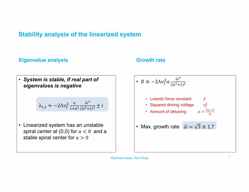
• � ≅ −2Λ����
���
����� �
• Lorentz force constantΛ
• Squared driving voltage ���
• Amount of detuning � =����
��
• Max. growth rate �� = 3 ≅ 1.7
Stability analysis of the linearized system
Growth rate
• System is stable, if real part of eigenvalues is negative
λ�,� ≈ −2Λ��� �
�������
����� � ± �
• Linearized system has an unstable spiral center at (0,0) for � < 0 and a stable spiral center for � > 0
7Ramona Leewe, Ken Fong
Eigenvalue analysis

Oscillation growth\decay rate of the nonlinear system
8Ramona Leewe, Ken Fong
simulation results of the nonlinear system
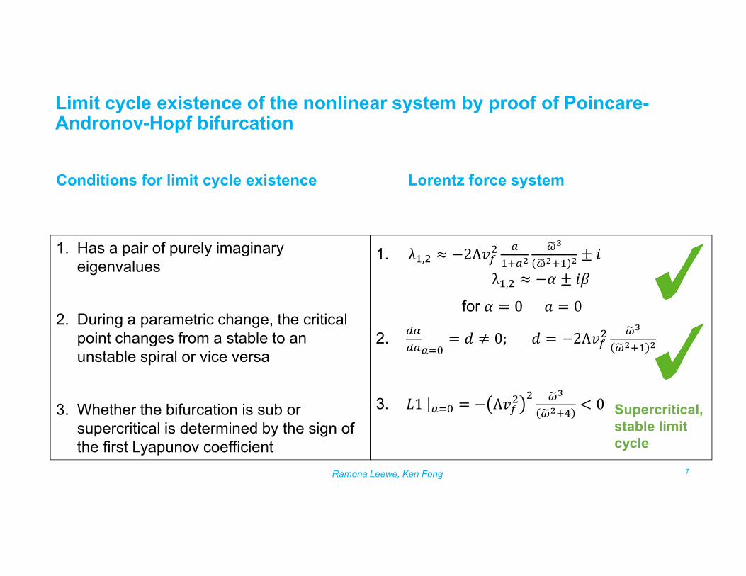
1. λ�,� ≈ −2Λ��� �
�������
����� � ± �
λ�,� ≈ −� ± ��
for � = 0 � = 0
2. ��
�����= � ≠ 0; � = −2Λ��
� ���
����� �
3. �1|��� = − Λ��� � ���
�����< 0
1. Has a pair of purely imaginary eigenvalues
2. During a parametric change, the critical point changes from a stable to an unstable spiral or vice versa
3. Whether the bifurcation is sub or supercritical is determined by the sign of the first Lyapunov coefficient
Limit cycle existence of the nonlinear system by proof of Poincare-Andronov-Hopf bifurcation
Conditions for limit cycle existence Lorentz force system
7Ramona Leewe, Ken Fong
Supercritical, stable limit cycle
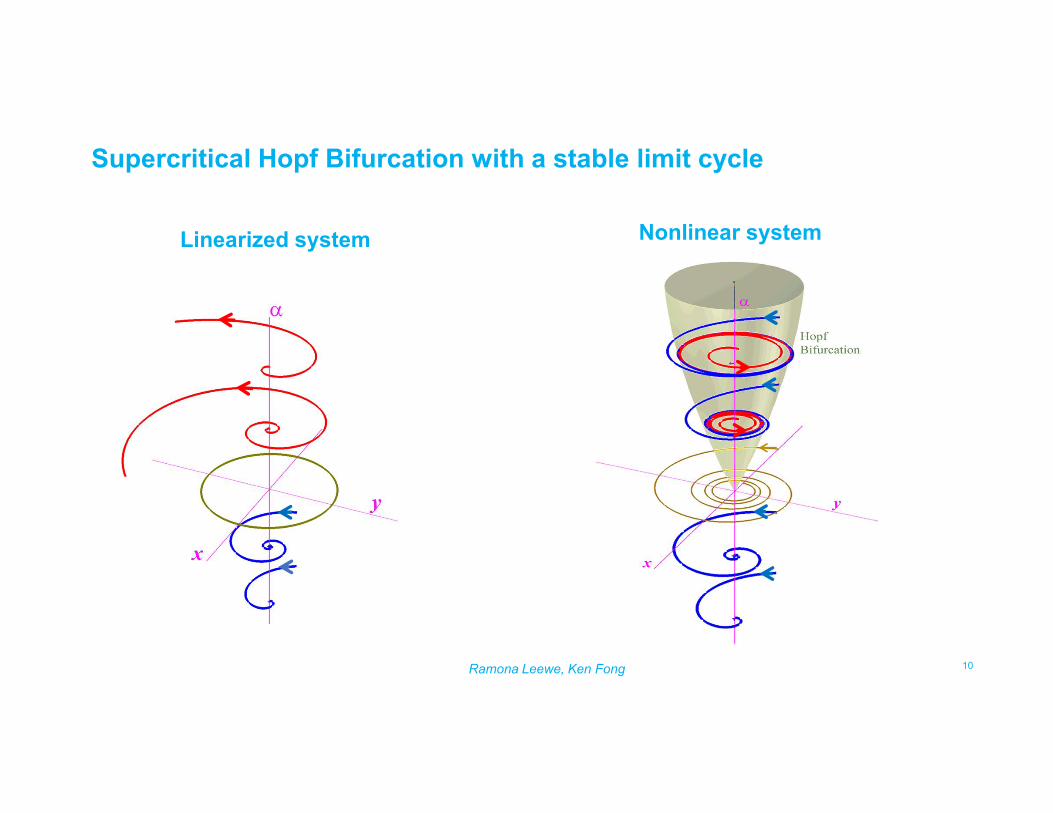
Linearized system Nonlinear system
10Ramona Leewe, Ken Fong
Supercritical Hopf Bifurcation with a stable limit cycle

Supercritical Hopf Bifurcation with a stable limit cycle
• Unstable within the cone � > 0 , small initial conditions
• Considering damping
• Cone position moves with increasing damping coefficient along the ‘a-Axis’
• Increases system stability
11Ramona Leewe, Ken Fong
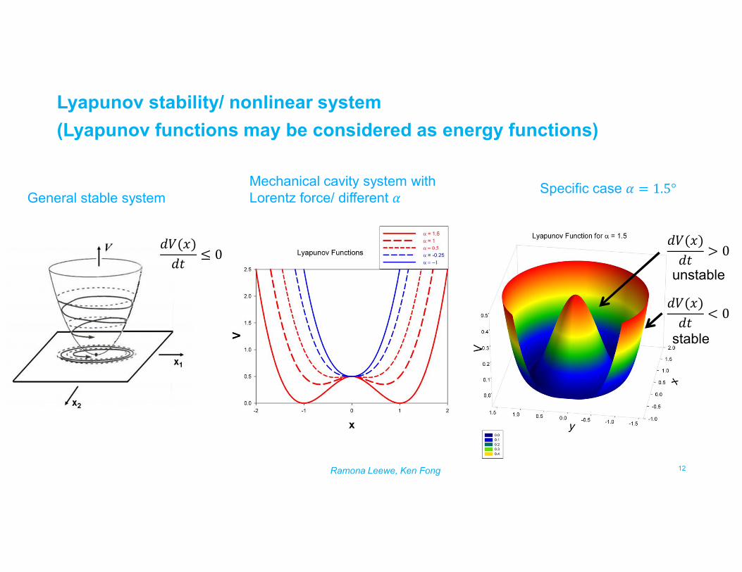
Lyapunov stability/ nonlinear system
(Lyapunov functions may be considered as energy functions)
12Ramona Leewe, Ken Fong
General stable systemMechanical cavity system with Lorentz force/ different �
Specific case � = 1.5°
��(�)
��≤ 0
��(�)
��> 0
��(�)
��< 0
unstable
stable
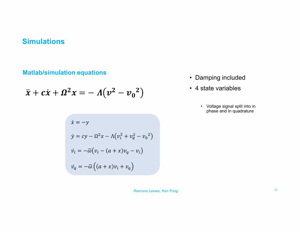
Simulations
Matlab/simulation equations• Damping included
• 4 state variables
• Voltage signal split into in phase and in quadrature
13Ramona Leewe, Ken Fong
� =̇ −�
�̇ = �� − Ω�� − Λ ��� + ��
� − ���
��̇ = −�� �� − � + � �� − ��
��̇ = −�� � + � �� + ��
�̈ + ��̇ + ��� = − � �� − ���

Simulation results
Stable: � < �, ������������� − 1.5° Unstable:� > �, �������������1.5°
14Ramona Leewe, Ken Fong

Conditions for Oscillations in RF cavity due to Lorentz force
• High electric field ~10��/�
• Insufficient rigidity in RF resonator
• Low mechanical damping
• Bandwidth of RF roughly double of mechanical mode oscillation
• Poor voltage regulation
• Driven frequency > RF resonance frequency
• Slow growth rate
• Non zero initial conditions
• High Q cavity
• Nb
• Metal
• 300Hz/160Hz
• Vector sum
• CW-operation
• Microphonics
15Ramona Leewe, Ken Fong

What can we do to suppress these instabilities?
• High electric field ~10��/�
• Insufficient rigidity in RF resonator
• Low mechanical damping
• Bandwidth of RF roughly double of mechanical mode oscillation
• Poor voltage regulation
• Driven frequency > RF resonance frequency
• Slow growth rate
• Non zero initial conditions
• Nothing
• Strengthen mechanically
• Add damping
• Nothing
• Avoid vector sum
• Tune for � < ��
• Pulsed-operation
• Active Microphonicsfeedback
• Active Lorentz force oscillation suppression
16Ramona Leewe, Ken Fong

Conclusion and lookout
• Field oscillation can occur at high field gradients
• It has a slow rise time
• First observed at TRIUMF’s e-LINAC in summer 2018
• It is suppressed under certain conditions
• Active Lorentz force oscillation suppression feasible? • Lorentz force affects the cavity acceleration (not the position)
• What variable could be measured?
• Phase lag between the mechanical detune and the electrical response
•� =̇ � + �̇
�̇ = � + �, � = ��������,
piezo is affecting the position, not a trivial cancellation feedback problem
• A deeper analysis of the presented results with respect to a feedback tuning system will be necessary
17Ramona Leewe, Ken Fong

18
Thank you for your consideration!

19Ramona Leewe, Ken Fong
Simulation results (increased detuning angle)
Unstable:� > ��������������5°