lorelei - expert-sleepers.co.uk
TRANSCRIPT

User ManualRevision 1.0
lorelei

Copyright © 2021 Expert Sleepers Ltd. All rights reserved.
This manual, as well as the hardware described in it, is furnished under licence and may be used or copied only in accordance with the terms of such licence. The content of this manual is furnished for informational use only, is subject to change without notice, and should not be construed as a commitment by Expert Sleepers Ltd. Expert Sleepers Ltd assumes no responsibility or liability for any errors or inaccuracies that may appear in this document.

Table of ContentsIntroduction......................................................................................................................................................................... 4Installation............................................................................................................................................................................ 4
Power requirements.................................................................................................................................................. 5Inputs and outputs........................................................................................................................................................... 5Controls.................................................................................................................................................................................. 5Wave shapes........................................................................................................................................................................ 5Cross-modulation/sync................................................................................................................................................. 7Calibration............................................................................................................................................................................ 9Where to get help............................................................................................................................................................. 9Acknowledgments........................................................................................................................................................... 9

IntroductionCongratulations on your purchase of an Expert Sleepers “Lorelei”. Please read this user manual before operating your new module.
Lorelei is a VCO (Voltage Controlled Oscillator) with quadrature sine outputs, waveshaping, and sync/cross-modulation options.
The module has three waveform outputs, all afected by the same waveshaping controls (a front panel knob and a CV input). The frst ofers a variable pulse width square wave. The remaining two ofer waveforms based on quadrature (i.e. 90 degrees out of phase) sine waves. The waveshape control progressively turns the frst sine output into a triangle-like waveform; the second sine output becomes a saw-like waveform.
The cross-modulation input is somewhat like the sync input found on more conventional VCOs, but it has more nuances of operation allowing for a wider choice of sounds.
The module is 100% analogue, using discrete transistor OTAs.
InstallationHouse the module in a Eurorack case of your choosing. The power connector is 16-pin Doepfer standard1. If using the power cable supplied with the module, the red edge of the cable is closest to the bottom edge of the PCB, and carries -12V. ("-12V" is marked on the PCB itself next to this end of the connector.) Be sure to connect the other end of the power cable correctly, again so -12V corresponds to the red stripe on the cable.
1 http://www.doepfer.de/a100_man/a100t_e.htm

Power requirements
Lorelei draws up to 55mA on the +12V rail, and 54mA on the -12V rail.
It does not use the 5V rail.
Inputs and outputsLorelei's input and output jack sockets are illuminated, lighting red for positive voltage and blue for negative voltage. (Audio appears purple, since it is a rapid alternation of positive and negative.)
Inputs with attenuators are indicated by a dotted line linking the socket to its corresponding attenuator knob.
From top to bottom, Lorelei's sockets are:
– Pitch CV input (1V/octave)
– Linear FM input
– Exponential FM input, with attenuator
– Cross-modulation/sync input
– Wave shape CV input, with attenuator
– Square/pulse output
– Sine/pseudo-triangle output
– Cosine/pseudo-saw output
ControlsIn addition to the three attenuators, there is an eight-position octave selection switch (white), a Tune control (blue), and a Shape control (green).
The Tune knob will adjust the oscillator pitch by approximately one octave up or down.
Wave shapesThe wave shape CV input and knob together simultaneously control the waveforms of Lorelei's three outputs.
A curious result of the exact nature of the wave shaping applied is that at the half-way point the perceived pitch of the sine and cosine outputs doubles.
Below are oscilloscope traces showing the three outputs as the Shape knob moves from 0 to 10.

Waveforms shown for Shapes of approximately:
0 2
3.5 5
6.5 8
10

Cross-modulation/syncIn a common-or-garden ramp-based analogue VCO, oscillator sync works by resetting the ramp integrator based on the frequency of the syncing signal. Lorelei works quite diferently, though similar efects can be obtained. In Lorelei, the sync input essentially prevents the oscillator from oscillating when the input is above a certain voltage (around 3.3V), but this is not an on-of thing – the efect gradually applies as the voltage increases. The upshot of this is that smooth waveforms (e.g. sine or triangle) for the syncing input produce a diferent efect to, say, square or pulse waveforms. Also, when using a pulse wave as the sync input, the pulsewidth of the signal also afects the result quite drastically. In the examples below, Lorelei's output is at the top (in green) and the sync input waveform is at the bottom (in magenta).
Sync from ±5V sine wave:
Sync from ±5V triangle wave:
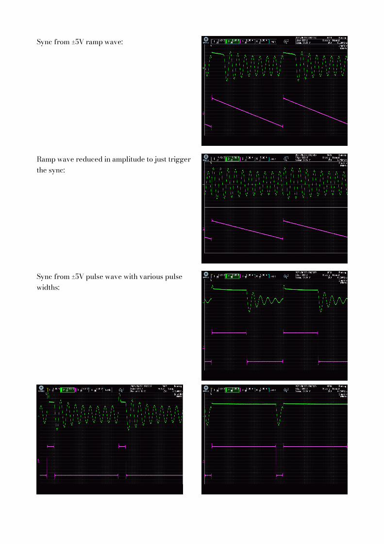
Sync from ±5V ramp wave:
Ramp wave reduced in amplitude to just trigger the sync:
Sync from ±5V pulse wave with various pulse widths:

CalibrationThere are two trim pots on the Lorelei PCB, as shown below:
“RV5”, marked “Amplitude”, sets the internal level of the module and so the operating point of the wave shaping. It should be set so that the waveform observed at the test point “TP2” is 2 Volts peak-to-peak. You should not need to adjust this unless you fnd that the output waveforms cannot be set to completely clean sine waves at either end of the wave shape knob.
“RV6”, marked “V/oct trim”, controls the pitch tracking of the oscillator. This needs to be set carefully to obtain the best possible tracking. It is factory calibrated, but you may fnd you need to recalibrate if your environmental conditions are much diferent to those in the factory, or simply as the module ages.
Where to get helpEmail, forum, and social media links can be found at the bottom of every page on our website2.
AcknowledgmentsBlack and white photography by Israel Denadai3.
2 https://www.expert-sleepers.co.uk3 http://israeldenadai.com.br/bw