long beach city hall
TRANSCRIPT

STRUCTURAL CALCULATIONS SEISMIC EVALUATION PEER REVIEW
Of
Long Beach City Hall Long Beach, CA
Prepared for:
City of Long Beach
Department of Public Works
333 West Ocean Boulevard
Long Beach, CA
Prepared by:
Nabih Youssef & Associates Structural Engineers
550 South Hope Street, Suite 1700 Los Angeles, California 90071
NYA Job # 13190.00
December 6, 2013

Long Beach City Hall Seismic Evaluation Peer Review Long Beach, California December 6, 2013
Nabih Youssef & Associates • Structural Engineers
TABLE OF CONTENTS 1 . 0 I N T R O D U C T I O N 1 . 1 General
1 . 2 Evaluation References 2 . 0 B U I L D I N G D E S C R I P T I O N 2 . 1 General 2 . 2 Gravity System
2 . 3 Lateral System 3 . 0 A N A L Y S I S
3 . 1 ETABS – Linear Dynamic Analysis 3 . 2 Perform 3D – Nonlinear Dynamic Analysis A P P E N D I X A – E T A B S I n p u t a n d R e s u l t s A P P E N D I X B – P e r f o r m 3 D I n p u t a n d R e s u l t s

Long Beach City Hall Seismic Evaluation Peer Review Long Beach, California December 6, 2013
Nabih Youssef & Associates • Structural Engineers
1 . 0 I N T R O D U C T I O N
1 . 1 G e n e r a l
This report contains the calculations from NYA’s seismic evaluation for the Long Beach City Hall building. The Long Beach City Hall Building consists of a 15 story steel tower above grade with one basement level. The building was constructed in 1976 and designed to the requirements of the 1970 UBC. The building is irregular-shaped in-plan with a square floor plate measuring approximately 112 feet by 112 feet and rectangular wings measuring approximately 36 feet by 30 feet oriented at 45 degrees at each corner. The typical story floor-to-floor height is 14 feet except at the Plaza Level and penthouse where the height is 42 feet and approximately 23 feet, respectively. The overall building height is 248 feet above the Plaza Level.
1 . 2 E v a l u a t i o n R e f e r e n c e s
The following documents and available information were examined in the evaluation:
• Original structural drawings by Bole & Wilson dated April, 1973
• Life-Safety Performance Evaluation Based on FEMA 310, Tier 2, TMAD Taylor and Gaines (No. 4105014), August 31, 2005.
• Preliminary Seismic Review Life Safety Performance Level Based on FEMA 310 Tier 1, Erkel, Greenfield and Associates, Inc. (No. 05-5061), February 21, 2005.
• The City of Long Beach City Hall FEMA 310 Tier 2 Evaluation Final Geologic, Seismic and Geotechnical Report, Earth Mechanics, Inc. (No. 05-110), July 18, 2005.
2 . 0 B U I L D I N G D E S C R I P T I O N
2 . 1 G e n e r a l
The Long Beach City Hall Building consists of a 15 story steel tower above grade with one basement level. The building was constructed in 1976 and designed to the requirements of the 1970 UBC. The building is irregular-shaped in-plan with a square floor plate measuring approximately 112 feet by 112 feet and rectangular wings measuring approximately 36 feet by 30 feet oriented at 45 degrees at each corner. The typical story floor-to-floor height is 14 feet except at the Plaza Level and penthouse where the height is 42 feet and approximately 23 feet, respectively. The overall building height is 248 feet above the Plaza Level.

Long Beach City Hall Seismic Evaluation Peer Review Long Beach, California December 6, 2013
Nabih Youssef & Associates • Structural Engineers
Figure 2.1 – Aerial view of site
2 . 2 G r a v i t y S y s t e m
The gravity framing system typically consists of the following:
• The typical floors are constructed of metal deck with lightweight concrete fill spanning to wide flange steel beams and girders that are supported by steel wide flange and built-up box columns.
• The columns located within the square floor plate terminate at the 2nd floor where 9 feet deep steel trusses transfer the axial loads to steel columns in the four wings and four heavy interior columns below the 2nd floor that are continuous to the foundation.
• The foundation system consists of 6 feet thick reinforced concrete mat footings supporting each wing and heavy interior column.
2 . 3 L a t e r a l S y s t e m
The seismic system of the building typically consists of the following:
• The lateral system of the tower consists of the metal deck with concrete fill roof and floor acting as structural diaphragms to transfer seismic inertia forces to welded steel moment frames, two 3-bay frames in each principal direction of the building.
• The frames are located within the square floor plate above the 2nd floor. At the 2nd floor, seismic forces are transferred from the moment frame columns through the diaphragm to perimeter steel trusses that transfer the forces to welded steel moment frames located in the building wings below the 2nd floor.
• There are two single-bay moment frames in each of the building wings. These frames are continuous to the foundation.
City Hall Building

Long Beach City Hall Seismic Evaluation Peer Review Long Beach, California December 6, 2013
Nabih Youssef & Associates • Structural Engineers
3 . 0 A N A L Y S I S
3 . 1 E T A B S – L i n e a r D y n a m i c A n a l y s i s
For confirmation of the results from the previous evaluations, a linear dynamic analysis was performed. The ETABS program was used to create a 3D model of the structure and a response spectrum analysis was performed. Key modeling assumptions were as follows:
• Semi-rigid diaphragms to account for floor plate irregularity
• 5% damping
• Rigid end offsets with 0.5 rigid zone factor The linear analysis of the structure in ETABS confirmed the findings of the previous evaluations. The major structural deficiencies noted were:
• Overstresses in the moment frames above and below the 2nd floor
• Inadequate level 2 diaphragm
• Inadequate transfer truss elements
• Overstresses at typical moment frame connections
Figure 3.1 – Isometric View of ETABS Model

Long Beach City Hall Seismic Evaluation Peer Review Long Beach, California December 6, 2013
Nabih Youssef & Associates • Structural Engineers
Figure 3.2 – Typical Plan View Above Level 2
Figure 3.3 – Typical Plan View Above Level 2 (Moment Frames in Red)

Long Beach City Hall Seismic Evaluation Peer Review Long Beach, California December 6, 2013
Nabih Youssef & Associates • Structural Engineers
Figure 3.4 – Isometric View – Lateral System Only
Figure 3.5 – Lateral System at Level 2 and Below

Long Beach City Hall Seismic Evaluation Peer Review Long Beach, California December 6, 2013
Nabih Youssef & Associates • Structural Engineers
Figure 3.6 – Mode 1 – T = 6.65 s

Long Beach City Hall Seismic Evaluation Peer Review Long Beach, California December 6, 2013
Nabih Youssef & Associates • Structural Engineers
Figure 3.7 – Mode 4 – T = 3.18 s

Long Beach City Hall Seismic Evaluation Peer Review Long Beach, California December 6, 2013
Nabih Youssef & Associates • Structural Engineers
Figure 3.8 – Mode 5 – T = 2.95 s
Long Beach City Hall Seismic Evaluation Peer Review Long Beach, California December 6, 2013
Nabih Youssef & Associates • Structural Engineers
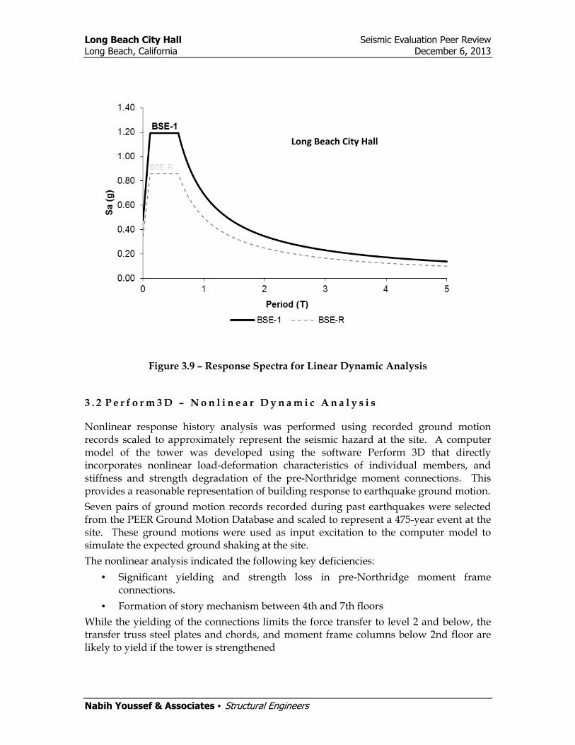
Figure 3.9 – Response Spectra for Linear Dynamic Analysis
3 . 2 P e r f o r m 3 D – N o n l i n e a r D y n a m i c A n a l y s i s
Nonlinear response history analysis was performed using recorded ground motion records scaled to approximately represent the seismic hazard at the site. A computer model of the tower was developed using the software Perform 3D that directly incorporates nonlinear load-deformation characteristics of individual members, and stiffness and strength degradation of the pre-Northridge moment connections. This provides a reasonable representation of building response to earthquake ground motion.
Seven pairs of ground motion records recorded during past earthquakes were selected from the PEER Ground Motion Database and scaled to represent a 475-year event at the site. These ground motions were used as input excitation to the computer model to simulate the expected ground shaking at the site.
The nonlinear analysis indicated the following key deficiencies:
• Significant yielding and strength loss in pre-Northridge moment frame connections.
• Formation of story mechanism between 4th and 7th floors
While the yielding of the connections limits the force transfer to level 2 and below, the transfer truss steel plates and chords, and moment frame columns below 2nd floor are likely to yield if the tower is strengthened
Long Beach City Hall

Long Beach City Hall Seismic Evaluation Peer Review Long Beach, California December 6, 2013
Nabih Youssef & Associates • Structural Engineers
Figure 4.1 – Perform Model 3D View
Figure 4.2 – Detail of Level 2 Transfer Truss Modeling
Steel Plate
Steel MF
Steel Truss
Collector

Long Beach City Hall Seismic Evaluation Peer Review Long Beach, California December 6, 2013
Nabih Youssef & Associates • Structural Engineers
Figure 4.3 – Hinge Definition for Typical pre-Northridge Moment Frame Connection
Figure 4.4 – 3D Deflected Shape (475 Year Northridge Event)

Long Beach City Hall Seismic Evaluation Peer Review Long Beach, California December 6, 2013
Nabih Youssef & Associates • Structural Engineers
Figure 4.5 – Typical Deflected Shape at Grid T12
Figure 4.6 – Connection Strength Loss Distribution

Long Beach City Hall Seismic Evaluation Peer Review Long Beach, California December 6, 2013
Nabih Youssef & Associates • Structural Engineers
Figure 4.7 – Exceedance of Beam Connection Strength Loss Limit State