logo! in details
TRANSCRIPT

5/12/2018 LOGO! in Details - slidepdf.com
http://slidepdf.com/reader/full/logo-in-details 1/146
L Innovative
Switching & Control
OGO! - The internalqualities
count

5/12/2018 LOGO! in Details - slidepdf.com
http://slidepdf.com/reader/full/logo-in-details 2/146
© Siemens AG 2009 - Subject to modifications
I IA AS F A PS4Logic module LOGO!
Introduction
Wiring
Integrated
functions
Operation ondevice
LOGO! SoftComfort V6.1
Application
example
LOGO! ±InnovativeSw
itching & Control ...In detail
The Original!
Introduction

5/12/2018 LOGO! in Details - slidepdf.com
http://slidepdf.com/reader/full/logo-in-details 3/146
© Siemens AG 2009 - Subject to modifications
I IA AS F A PS4Logic module LOGO!
Introduction
Wiring
Integrated
functions
Operation ondevice
LOGO! SoftComfort V6.1
Application
example
LOGO! in detail overview
Wiring Hardware assembly
Connecting power supply
Connecting inputs and outputs
Switch-on behavior
Integrated functions Connectors
Basic functions
Special functions
Operation on device Control for operation
First program
LOGO! in run mode
Configuring LOGO!
LOGO! Soft Comfort V6.1 Help functions
Realizing typical tasks step by step
Modem wizard
Other options
Application example Control of bottle filling conveyor
Introduction

5/12/2018 LOGO! in Details - slidepdf.com
http://slidepdf.com/reader/full/logo-in-details 4/146
© Siemens AG 2009 - Subject to modifications
I IA AS F A PS4Logic module LOGO!
Introduction
Wiring
Integrated
functions
Operation ondevice
LOGO! SoftComfort V6.1
Application
example
LOGO! wiring
N
K2
L1
K2
I :
0.. 123456789
1..0123456789
2..01234
4
Wiring

5/12/2018 LOGO! in Details - slidepdf.com
http://slidepdf.com/reader/full/logo-in-details 5/146
© Siemens AG 2009 - Subject to modifications
I IA AS F A PS4Logic module LOGO!
Introduction
Wiring
Integrated
functions
Operation ondevice
LOGO! SoftComfort V6.1
Application
example
LOGO! ..0BA5 hardware structure
Maximum configuration: 24 digital inputs + 8 analog inputs
+16 digital outputs + 2 analog outputs
Power supply
Power supply for expansion modules
RUN/STOP
4 outputs
4 inputs
8 inputs
Switch for
electricalconnection
4 outputs
Backlit display
Adjustable contrast
The internal
qualities
count
Wiring
Connectioninterface for LOGO! TD
E-Stand (ESx)

5/12/2018 LOGO! in Details - slidepdf.com
http://slidepdf.com/reader/full/logo-in-details 6/146
© Siemens AG 2009 - Subject to modifications
I IA AS F A PS4Logic module LOGO!
Introduction
Wiring
Integrated
functions
Operation ondevice
LOGO! SoftComfort V6.1
Application
example
To connect LOGO! to the power supply:
ML + I1 I2 I3 I4 I5
L 1L +
NM
I1 I2 I3 I4L1 N
Protection by fuseif required (recommended) for:
12/24 RC...: 0.8 A24: 2.0 A
With voltage spikes, use a varistor (MOV) with an operating voltageat least 20% higher than nominalvoltage.
LOGO! ..... with
AC supply voltageLOGO! ..... with
DC supply voltage
LOGO! wiring
Wiring

5/12/2018 LOGO! in Details - slidepdf.com
http://slidepdf.com/reader/full/logo-in-details 7/146
© Siemens AG 2009 - Subject to modifications
I IA AS F A PS4Logic module LOGO!
Introduction
Wiring
Integrated
functions
Operation ondevice
LOGO! SoftComfort V6.1
Application
example
Connecting LOGO! inputs
Connect sensors to the inputs. Sensors may be:
pushbuttons, switches, photoelectric barriers, etc.
temperature, pressure or ultrasound sensors (Beros) etc., with 0...10V outputs directly atthe 4 analog inputs of the 12 and 24 V DC basic devices or the analog module AM2
or the appropriate device with current output 0...20mA/4...20mA to the inputs of theanalog module AM2
or connect up to 2 resistance thermometer PT100 to AM2 PT100 in 2 or 3 wire connectiontechnology
LOGO! 12/24 ...L+
ML+ I1 I2 I3 I4 I5 I8
M
The inputs of these devices aregrouped into 2 blocks of 4 I each. Different phases areonly possible between, notwithin the blocks.
LOGO! 230 ...
L1
N
NL1 I1 I2 I3 I4 I5 I6
L3L2
With 2-wire connections no
correction of the impedance of
the measurement line occurs.
3-wire connection suppresses
this influence.
2-wire technology 3-wire technology
The inputs of these devices are
non±isolated and therefore
require the same reference
potential (ground) as the power
supply.
Wiring

5/12/2018 LOGO! in Details - slidepdf.com
http://slidepdf.com/reader/full/logo-in-details 8/146
© Siemens AG 2009 - Subject to modifications
I IA AS F A PS4Logic module LOGO!
Introduction
Wiring
Integrated
functions
Operation ondevice
LOGO! SoftComfort V6.1
Application
example
Connecting LOGO! outputs
You can connectdifferent loads to theoutputs, e.g.:
lights
motors
switches
etc. ...
LOGO! with
transistor outputs
LOGO! with
relay outputs
max. switched current per output is 0.3 A
DM8 24
Q5 M Q6 M
load load
Q1 M Q2 M
max. switched current per output is 10 A /for expansion modules 5 A
Q2Q11 21 2
Q51 2
Q61 2
DM8...R
loadloadN / M
L1 / L+
Wiring

5/12/2018 LOGO! in Details - slidepdf.com
http://slidepdf.com/reader/full/logo-in-details 9/146
© Siemens AG 2009 - Subject to modifications
I IA AS F A PS4Logic module LOGO!
Introduction
Wiring
Integrated
functions
Operation ondevice
LOGO! SoftComfort V6.1
Application
example
Ground
Profile rail
Connecting LOGO! outputs
LOGO! with
analog outputs
You can connectdifferent devices toanalog outputs, e.g.:
frequency converter tocontrol drives
Output signals: *)
0-10V
0-20m A
4-20m A
Wiring
*) 6ED1 055-1MM00-0B A0: 0..10V6ED1 055-1MM00-0B A1: 0..10V and 0/4..20m A.

5/12/2018 LOGO! in Details - slidepdf.com
http://slidepdf.com/reader/full/logo-in-details 10/146
© Siemens AG 2009 - Subject to modifications
I IA AS F A PS4Logic module LOGO!
Introduction
Wiring
Integrated
functions
Operation ondevice
LOGO! SoftComfort V6.1
Application
example
Connecting LOGO! TD text display
LOGO! ..0BA6 basicmodule
Connection interface for LOGO! TD Cable
unipolar power supplyconnector
12V DC, 24V AC/DCRecommended fuse: 0,5A
Function keysStandard
LOGO! keys
LOGO! TD Cable 2,5m,extendable to up to 10meters with standard
Sub-D serial cable
Wiring

5/12/2018 LOGO! in Details - slidepdf.com
http://slidepdf.com/reader/full/logo-in-details 11/146
© Siemens AG 2009 - Subject to modifications
I IA AS F A PS4Logic module LOGO!
Introduction
Wiring
Integrated
functions
Operation ondevice
LOGO! SoftComfort V6.1
Application
example
LOGO! reaction when switched on depends on:
whether a program is stored in the internal LOGO! memory
or
whether a memory card (memory module) is connected
No program onmemory card and noprogram in internalmemory
Program on memorycard or program ininternal memory
Warning!If there is a program on the memorycard, it is automatically
copied to the internal LOGO! memorywhen switching on . Any program inthe internal LOGO! memory isoverwritten.
LOGO!
> Program..
Card..
Setup..
Start
LOGO!
No Program
Press ESC
s
s
Wiring

5/12/2018 LOGO! in Details - slidepdf.com
http://slidepdf.com/reader/full/logo-in-details 12/146
© Siemens AG 2009 - Subject to modifications
I IA AS F A PS4Logic module LOGO!
Introduction
Wiring
Integrated
functions
Operation ondevice
LOGO! SoftComfort V6.1
Application
example
LOGO! reaction when switched on depends on:
Prior to power-off After power-on
In
editing mode or menu in stopstatus
InRUN time
in which state LOGO! was prior to POWER±OFF
Prior to power-off After power-on
LOGO!
> Program..
Card..Setup..
Start
LOGO!
Q1
LOGO!
I :
0.. 123456789
1..0123456789
2..01234
LOGO!
I :
0.. 123456789
1..0123456789
2..01234
s
ss
s
Wiring

5/12/2018 LOGO! in Details - slidepdf.com
http://slidepdf.com/reader/full/logo-in-details 13/146
© Siemens AG 2009 - Subject to modifications
I IA AS F A PS4Logic module LOGO!
Introduction
Wiring
Integrated
functions
Operation ondevice
LOGO! SoftComfort V6.1
Application
example
Connectors (CO)
I1 Q1
I2 Q2
I3 Q3
I4 Q4
I5 .
I6 .
I7 .
I8 .
. .
. .
I21 Q13
I22 Q14I23 Q15
I24 Q16
AI1
AI2
AI3
.
.
AI8
M1
.
.
M8
M25
M26M27
hi
lo
Inputs/outputsbasic/pure-variants
AnalogI/O
Signal statusÄ1³Ä0³
I3-I6 up to 5 KHzswitching-frequency on DC
powered options
Cursor Keys
AQ1
AQ2
AM1
.
AM6
C
C
C
C
Flags/Analog flags
Initialization flag
Integrated
functions
Connectors
F1
F2
F3
F4
LOGO! TDFunctionkeys
Backlight flags
Character set flag

5/12/2018 LOGO! in Details - slidepdf.com
http://slidepdf.com/reader/full/logo-in-details 14/146
© Siemens AG 2009 - Subject to modifications
I IA AS F A PS4Logic module LOGO!
Introduction
Wiring
Integrated
functions
Operation ondevice
LOGO! SoftComfort V6.1
Application
example
8 basicfunctions
Basic functions
AND AND(edge)
NAND NAND(edge)
OR NOR XOR NOT
The
internalqualities
count
Integrated
functions

5/12/2018 LOGO! in Details - slidepdf.com
http://slidepdf.com/reader/full/logo-in-details 15/146
© Siemens AG 2009 - Subject to modifications
I IA AS F A PS4Logic module LOGO!
Introduction
Wiring
Integrated
functions
Operation ondevice
LOGO! SoftComfort V6.1
Application
example
AND function
Output of the AND function is 1 onlywhen all inputs are 1.If one input pin of this block is notconnected, the status is automatically 1.
Logic table for AND block:
A look at the circuit diagram shows that the light H1 is only on whenS1 and S2 and S3 are closed. Input and output states are dependenton each other.
The circuit to the right is called AND logic.
In words contact S1 and S2 and S3 have to be closed for the light toburn.
Symbol for this connection is .
Series circuitnormally open
contact&S1
S2
x
H1
AND
S3
S2
S3
H1
S1
Input 3 Output
0 0 0 0
0 0 1 0
0 1 0 0
0 1 1 0
1 0 0 0
1 0 1 0
1 1 0 0
1 1 1 1
Input 2Input 1
Integrated
functions

5/12/2018 LOGO! in Details - slidepdf.com
http://slidepdf.com/reader/full/logo-in-details 16/146
© Siemens AG 2009 - Subject to modifications
I IA AS F A PS4Logic module LOGO!
Introduction
Wiring
Integrated
functions
Operation ondevice
LOGO! SoftComfort V6.1
Application
exampleOutput of the OR function is 1, when atleast one input is 1.If one input pin of this block is notconnected, the status is automatically 0.
To turn the lamp H2 on, the contact S1 or S2 or S3 have to beclosed. The dependence of output states from inputs states iscalled OR logic.
In words at least one of the contacts S1 or S2 or S3 have to beclosed for the lamp H2 to light up.
Symbol for this connection is .
OR function
Logic table for OR block:
Parallel circuitnormally open contact
>S1
S2
S3H2
OR
x
S1 S2
H2
S3
Input 3 Output
0 0 0 0
0 0 1 1
0 1 0 1
0 1 1 1
1 0 0 1
1 0 1 1
1 1 0 1
1 1 1 1
Input 2Input 1
Integrated
functions

5/12/2018 LOGO! in Details - slidepdf.com
http://slidepdf.com/reader/full/logo-in-details 17/146
© Siemens AG 2009 - Subject to modifications
I IA AS F A PS4Logic module LOGO!
Introduction
Wiring
Integrated
functions
Operation ondevice
LOGO! SoftComfort V6.1
Application
example
AND with edge triggering
Output of AND with edge triggering is 1, only when allinputs are 1 and in the previous cycle at least oneinput was 0. If one input pin of this block is notconnected, the status is automatically 1.
AND with edge triggering
S1
S2
S3
H2
S1
S2
H2
S3
Electro mechanical counter
5160
&S1
S2
x
H2S3
Integrated
functions

5/12/2018 LOGO! in Details - slidepdf.com
http://slidepdf.com/reader/full/logo-in-details 18/146
© Siemens AG 2009 - Subject to modifications
I IA AS F A PS4Logic module LOGO!
Introduction
Wiring
Integrated
functions
Operation ondevice
LOGO! SoftComfort V6.1
Application
example
A look at the circuit diagram shows that the light H2 is not on,only when all contacts are switched.The circuit to the right is called NAND logic.
In words S1 and S2 and S3 have to be switched for the light H2not to burn.
Symbol for this connection is .
NAND (not-AND) function
Output of NAND is 0, only when allinputs are 1.If one input pin of this block is notconnected, the status is automatically 1.
Logic table for NAND block:
Parallel circuitnormally closed
contact
S1 S2 S3
H2
&S1
S2
S3H2
NAND
xInput 3 Output
0 0 0 1
0 0 1 1
0 1 0 1
0 1 1 1
1 0 0 1
1 0 1 1
1 1 0 1
1 1 1 0
Input 2Input 1
Integrated
functions
5/12/2018 LOGO! in Details - slidepdf.com
http://slidepdf.com/reader/full/logo-in-details 19/146
© Siemens AG 2009 - Subject to modifications
I IA AS F A PS4Logic module LOGO!
Introduction
Wiring
Integrated
functions
Operation ondevice
LOGO! SoftComfort V6.1
Application
example
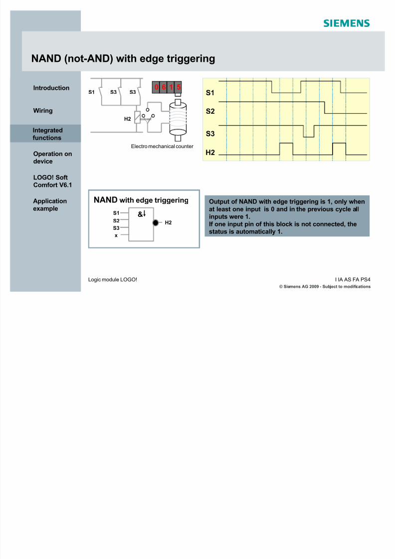
NAND (not-AND) with edge triggering
S1
S2
S3
H2
Output of NAND with edge triggering is 1, only when
at least one input is 0 and in the previous cycle allinputs were 1.If one input pin of this block is not connected, thestatus is automatically 1.
Electro mechanical counter
NAND with edge triggering
S1 S3 S3
H2
5160
&S1
S2
S3H2
x
Integrated
functions

5/12/2018 LOGO! in Details - slidepdf.com
http://slidepdf.com/reader/full/logo-in-details 20/146
© Siemens AG 2009 - Subject to modifications
I IA AS F A PS4Logic module LOGO!
Introduction
Wiring
Integrated
functions
Operation ondevice
LOGO! SoftComfort V6.1
Application
example
A look at the circuit diagram shows that the light H1 is only on,when the normally closed contact S1 and S2 and S3 are notswitched.The circuit to the right is called NOR logic.
In words when S1 or S2 or S3 are switched, the light is not on.Symbol for this connection is .
NOR (not-OR) function
Output of NAND is 1, only when all inputsare 0. As soon as any input is switched(status 1), the output is switched off. If oneinput pin of this block is not connected, thestatus is automatically 0.
Series circuitnormally closed
contact
Logic table for NOR block:
NOR
>1S1
S2
S3H1
x
S1
S2
H1
S3
Input 3 Output
0 0 0 1
0 0 1 0
0 1 0 0
0 1 1 0
1 0 0 0
1 0 1 0
1 1 0 0
1 1 1 0
Input 2Input 1
Integrated
functions

5/12/2018 LOGO! in Details - slidepdf.com
http://slidepdf.com/reader/full/logo-in-details 21/146
© Siemens AG 2009 - Subject to modifications
I IA AS F A PS4Logic module LOGO!
Introduction
Wiring
Integrated
functions
Operation ondevice
LOGO! SoftComfort V6.1
Application
example
XOR function
Output of XOR is 1, when inputs havedifferent states.If one input pin of this block is notconnected, the status is automatically 0.
XOR
A look at the circuit diagram shows that the light H1 is only on,when only one of either S1 or S2 is switched.This circuit is called XOR logic.In words when either contact S1 or contact S2 are switched, the
light is on.Symbol for this connection is .
Logic table for XOR block:
Input 2 Output0 0 0
0 1 1
1 0 1
1 1 0
Input 1
=1S1
S2
H1
S1
S2
H1Integrated
functions

5/12/2018 LOGO! in Details - slidepdf.com
http://slidepdf.com/reader/full/logo-in-details 22/146
© Siemens AG 2009 - Subject to modifications
I IA AS F A PS4Logic module LOGO!
Introduction
Wiring
Integrated
functions
Operation ondevice
LOGO! SoftComfort V6.1
Application
example
NOT function
Output is 1, when the input is 0, i.e. NOT inverts the statusat the input.The advantage of NOT is for instance: You will not need anormally closed contact any more for LOGO!. You can use anormally open contact and change it with NOT to a normallyclosed contact.If the input pin of this block is not connected, the status isautomatically 1.
NOT
1
S1 H1
A look at the circuit diagram shows that the light H1 is only on,
when the switch S1 is not switched.
This circuit is called NOT logic.
Symbol for this connection is .
Logic table for NOT block:
Output
0 1
1 0
Input 1
S1
H1
K1
Integrated
functions

5/12/2018 LOGO! in Details - slidepdf.com
http://slidepdf.com/reader/full/logo-in-details 23/146
© Siemens AG 2009 - Subject to modifications
I IA AS F A PS4Logic module LOGO!
Introduction
Wiring
Integrated
functions
Operation ondevice
LOGO! SoftComfort V6.1
Application
example
Special functions - overview
31specialfunctions
On-delay On-/ Off-delay
Up/Downcounter
Randomgenerator
Threshold trigger
Multiple functionswitch
Off-delay
Latching relay
Wiping relay(pulse output)
Yearlytimer
Hourscounter
Stairwaylighting switch
RetentiveOn-delay
Message text
Analog threshold
trigger
Analog comparator
Softkey
Edge triggeredwiping relay
Weeklytimer
Shift register
Analog differential
trigger
Analog
watchdog
Analog amplifier
Pulse relay
Pulse generator
PI controller Ramp
Analog
MUX
Timer
Counter
Miscellaneous
Analog
Integrated
functions
Analog MathError Detection
PWM
Analog Math

5/12/2018 LOGO! in Details - slidepdf.com
http://slidepdf.com/reader/full/logo-in-details 24/146
© Siemens AG 2009 - Subject to modifications
I IA AS F A PS4Logic module LOGO!
Introduction
Wiring
Integrated
functions
Operation ondevice
LOGO! SoftComfort V6.1
Application
example
Timer ± On-delay
Description of the function:
With 0 to 1 transition of input Trg the timer starts. If the status of input Trg is 1 for longenough, the output is set to 1 on expiration of the time T. The output follows the input withon delay. The output is reset to 0 when the status at input Trg is 0.If the status of input Trg changes to 0 before the time T has expired, the time is reset. Thetime elapsed is reset after a power failure.
A look at the circuit diagram shows that the motor only starts after expiry of the delay time.
This function is called On-delay.
In words the motor will be switch on with a programmed ON delaytime.
Symbol for this function is .
S1
K1
K1
M
Diagram:
Trg
Q
Ta
T T
(Timer active)
Integrated
functions

5/12/2018 LOGO! in Details - slidepdf.com
http://slidepdf.com/reader/full/logo-in-details 25/146
© Siemens AG 2009 - Subject to modifications
I IA AS F A PS4Logic module LOGO!
Introduction
Wiring
Integrated
functions
Operation ondevice
LOGO! SoftComfort V6.1
Application
example
Description of the function:
When the input Trg is 1, the output Q is switched instantaneously to 1. When the status of Trg changes from 1 to 0, the timer will be activated. The output remains set. When the timer reaches the configured value (Ta=T), output Q is reset to 0. When input Trg is switched onand off again, the time Ta restarts. Input R (Reset) is used to reset the time Ta and theoutput before Ta has expired.
Timer ± Off-delay
A look at the circuit diagram shows that the motor only stops after expiry of the delay time.
This function is called Off-delay.
In words the motor will be switch off with a programmed OFF delaytime.
Symbol for this function is .
S1
K1
K1
M
(Timer active)
Trg
Q
Ta T
R
T
Diagram:
Integrated
functions

5/12/2018 LOGO! in Details - slidepdf.com
http://slidepdf.com/reader/full/logo-in-details 26/146
© Siemens AG 2009 - Subject to modifications
I IA AS F A PS4Logic module LOGO!
Introduction
Wiring
Integrated
functions
Operation ondevice
LOGO! SoftComfort V6.1
Application
example
Timer ± On-/Off-delay
A look at the circuit diagram shows that:
when S1 is closed, contact K1 closes with a delaytime and the motor runs.
when S1 is opened, contact K2 opens with a delaytime and the motor stops.
This function is called On-/Off-delay. In words the motor isswitched on and off with a programmed delay time.
Symbol for this function is .
Description of the function:
The time TH starts after a 0 to 1 transition at input Trg. If the status at input Trg is 1 for theduration of the time TH, the output is set to 1 on expiration of the time TH.(the output follows the input on delayed). When the status at input returns to 0, TL starts. If the status at input Trg is 0 for the duration of time TL, the output is set to 0 on expiration of the time TL.
Trg
TL
Q
TH
Diagram:
K1
S1 K1
MK2
K2
Integrated
functions

5/12/2018 LOGO! in Details - slidepdf.com
http://slidepdf.com/reader/full/logo-in-details 27/146
© Siemens AG 2009 - Subject to modifications
I IA AS F A PS4Logic module LOGO!
Introduction
Wiring
Integrated
functions
Operation ondevice
LOGO! SoftComfort V6.1
Application
example
Timer ± Retentive On-delay
Description of the function:
The current time Ta starts with a 0 to 1 transition at input Trg. Output Q is set to 1 when Tareaches the time T. The output Q is only reset to 0 when the status at input R is 1. Further switching actions at input Trg have no influence on output Q.
A look at the circuit diagram shows that the motor M startsdelayed after pressing the pushbutton S1. Pushbutton S2(n.c. contact) stops the motor again.
This function is called retentive On-delay.
Symbol for this connection is .
S2
K1
K2
M
S1 K1 K1
K2
Trg
R
Ta
Q
T
Diagram:
Integrated
functions

5/12/2018 LOGO! in Details - slidepdf.com
http://slidepdf.com/reader/full/logo-in-details 28/146
© Siemens AG 2009 - Subject to modifications
I IA AS F A PS4Logic module LOGO!
Introduction
Wiring
Integrated
functions
Operation ondevice
LOGO! SoftComfort V6.1
Application
example
Timer ± Wiping relay (pulse output)
A look at the circuit diagram shows that the light H1 is only on,when the switch S1 is closed, but only as long as the set time attimer T1.
Symbol for this connection is .
T1
S1
H1
T1
Description of the function:
When the input Trg is set to 1, the output Q is immediately switched to 1. The current timeTa starts in LOGO! at the same time and the output remains set. When Ta reaches the valuespecified in T (Ta=T), the status of output Q is reset to 0 (pulse output). On input Trgtransition from 1 to 0 before the specified time has expired, the output follows immediatelywith a 1 to 0 transition.
Trg
Ta
Q
Diagram:
Integrated
functions

5/12/2018 LOGO! in Details - slidepdf.com
http://slidepdf.com/reader/full/logo-in-details 29/146
© Siemens AG 2009 - Subject to modifications
I IA AS F A PS4Logic module LOGO!
Introduction
Wiring
Integrated
functions
Operation ondevice
LOGO! SoftComfort V6.1
Application
example
Timer ± Edge triggered wiping relay
T1
S1
H1
T1
T1
Description of the function:
The output status is switched to 1 after the input Trg is set to 1. Time Ta is started at thesame time. After Ta has reached the value specified in T (Ta=T) the output Q status is resetto 0 (pulse output). If input Trg changes again from 0 to 1 (retriggering) before the specifiedtime has expired, the time Ta is reset and theoutput remains switched on.
Trg
Ta
Q
T T
Diagram:
A look at the circuit diagram shows that the light H1 remains onfor the time specified on the timer T1 when the switch S1 isclosed.
Symbol for this connection is .
Integrated
functions

5/12/2018 LOGO! in Details - slidepdf.com
http://slidepdf.com/reader/full/logo-in-details 30/146
© Siemens AG 2009 - Subject to modifications
I IA AS F A PS4Logic module LOGO!
Introduction
Wiring
Integrated
functions
Operation ondevice
LOGO! SoftComfort V6.1
Application
example
Timer ± Weekly timer
The output is controlled via a specified on±/off±date. The function supports anycombination of weekdays. You select theactive weekdays by deselecting the inactivedays.
Wednesday
Monday
Description of the function:
Every weekly timer has three cams. You can configure a time hysteresis for each cam. Within the cam setting youspecify the on/off times.
If you enable ³pulse output´, the timer will be reset after one cycle. ³Pulseoutput´ applies to all three cams.
MonTueWedThursFri Sa So On Off
07:
30 16 05Cam 1
08 : 00 12 00Cam 2
10:
00 12 30Cam 3
Integrated
functions

5/12/2018 LOGO! in Details - slidepdf.com
http://slidepdf.com/reader/full/logo-in-details 31/146
© Siemens AG 2009 - Subject to modifications
I IA AS F A PS4Logic module LOGO!
Introduction
Wiring
Integrated
functions
Operation ondevice
LOGO! SoftComfort V6.1
Application
example
Timer ± Yearly timer
Description of the function:
Every yearly timer has an on- and off-timer. At the
specified on-time the yearly timer switches on the output.At the specified off±time the yearly timer switches off theoutput. The off±date specifies the day/year on which theoutput is reset to 0 again.
By selecting the option field
³Monthly´, the timer switches on or off at a specifiedday each month. ³Yearly´, the timer switches on or off each year at aspecified month and day. ³Pulse Output´, the timer output switches on at the
specified On Time for one cycle. Then it is reset.
Jan Feb Mar Apr May Jun Jul Aug Sep Oct Nov Dec
On 05.10 Off 10.20
15.05.200515.05.2005 08.11.2005 08.11.2005
Integrated
functions

5/12/2018 LOGO! in Details - slidepdf.com
http://slidepdf.com/reader/full/logo-in-details 32/146
© Siemens AG 2009 - Subject to modifications
I IA AS F A PS4Logic module LOGO!
Introduction
Wiring
Integrated
functions
Operation ondevice
LOGO! SoftComfort V6.1
Application
example
Timer ± Asynchronous pulse generator
The pulse profile of the output can becustomized via pulse/ pause ratio.
Symbol for this function is .
Description of the function:
In the parameters you can adjust the pulse period and the pause width. With input INV you
can also invert the output. You can customized the time period in seconds, minutes or hours. The time basis of both parameters can be set independently. The input block INVonly negates the output if it is enabled via EN.
Diagram:
En
Q
pulse period / pause width
Inv
Integrated
functions

5/12/2018 LOGO! in Details - slidepdf.com
http://slidepdf.com/reader/full/logo-in-details 33/146
© Siemens AG 2009 - Subject to modifications
I IA AS F A PS4Logic module LOGO!
Introduction
Wiring
Integrated
functions
Operation ondevice
LOGO! SoftComfort V6.1
Application
example
Timer ± Random generator
Description of the function:
With a 0 to 1 transition of the input En a random time e.g. between 0 and 10 seconds isstarted. The output is set to 1 on expiration of the on delay time, if the input En is 1 atleast for the duration of the on delay time. The time is reset if the status at input Enreturns to 0 before the on delay time has expired. When the input En changes from 1 to0, a random off delay time between 0 and e.g. 15 seconds is started. The time is reset if the status at input En returns to 1 before the on delay time has expired.
With a random generator the output isswitched on and off again within a specifiedtime.
Symbol for this function is .
En
Q
max. ON delay / max. OFF delay
Q
Diagram:Integrated
functions

5/12/2018 LOGO! in Details - slidepdf.com
http://slidepdf.com/reader/full/logo-in-details 34/146
© Siemens AG 2009 - Subject to modifications
I IA AS F A PS4Logic module LOGO!
Introduction
Wiring
Integrated
functions
Operation ondevice
LOGO! SoftComfort V6.1
Application
example
Timer ± Stairway lighting switch
The input pulse (edge control) starts aspecified time. The output is reset onexpiration of this time. Prior to the expiration
of this time (e.g. 15 s) an off pre±warning isgenerated.
Symbol for this function is .
Description of the function:
With a 0 to 1 transition at input Trg, the current time starts and the output Q is set to 1. E.g.15 s before Ta reaches the time T, the output Q is reset to 0 for a time of 1 s (configurabletime). When Ta reaches the time T, the output Q is reset to 0. When input Trg is switched onand off again before Ta expires, Ta is reset (retriggering option).
Ta
Trg
Q
T (OFF delay)
1s
15s
Diagram:
Integrated
functions

5/12/2018 LOGO! in Details - slidepdf.com
http://slidepdf.com/reader/full/logo-in-details 35/146
© Siemens AG 2009 - Subject to modificationsI IA AS F A PS4Logic module LOGO!
Introduction
Wiring
Integrated
functions
Operation ondevice
LOGO! SoftComfort V6.1
Application
example
Switch with two different functions:
Pulse switch with off delay
Switch (continuous lighting)
Symbol for this function is .
Timer ± Multiple function switch
Description of the function:
The output Q is set to 1 with a 0 to 1 transition of the status at input Trg. When the input Trgchanges to 0 before expiration of the continuous lighting time, the output resets to 0 withan off delay of e.g. 5 seconds. With a 0 to 1 transition of the status at input Trg and if thestatus ¶1¶ is set at least for the duration of e.g. 20 seconds, the continuous lighting functionis enabled and the output Q is
switched on continuously. If the input Trg is switched once again from 0 to 1 and again to0, the output Q is switched off.
Q
Trg
5s >20s
Diagram:Integrated
functions

5/12/2018 LOGO! in Details - slidepdf.com
http://slidepdf.com/reader/full/logo-in-details 36/146
© Siemens AG 2009 - Subject to modificationsI IA AS F A PS4Logic module LOGO!
Introduction
Wiring
Integrated
functions
Operation ondevice
LOGO! SoftComfort V6.1
Application
example
Counter ± Up and Down counter
A look at the circuit diagram shows that the switch S1 triggers the counter pulses. SwitchS2 determines whether the counter increases or decreases. When the counter statusreaches a value >= 5, the light switches on.
Description of the function:
With every positive edge at input Cnt the internal counter increments (Dir = 0) or decrements (Dir = 1) by one count. Output Q is set to 1 when the internal value is greater than or equal to the value specified in Par. You can use reset input R to reset the output and
the internal count value to the start value. When R=1, the output is 0 and the pulses at inputCnt are not counted.
If you set a ³Start Value´ the counter begins to count either up or down from this value.
C1
S1
S2
+-
>=5
H1
Diagram:
Q
Cnt
Dir
R
12
34
56
54
32
34
56
01
23
Counter
Integrated
functions

5/12/2018 LOGO! in Details - slidepdf.com
http://slidepdf.com/reader/full/logo-in-details 37/146
© Siemens AG 2009 - Subject to modificationsI IA AS F A PS4Logic module LOGO!
Introduction
Wiring
Integrated
functions
Operation ondevice
LOGO! SoftComfort V6.1
Application
example
Counter ± Hours counter
Description of the function:
The hours counter monitors the input En. As long as the status of this input is 1, LOGO!determines the expired time OT and the time±to±go MN. LOGO! displays the times inparameter assignment mode. Output Q is set to 1 when the time±to±go MN = 0. Use input R
to reset output Q and time±to±go counter to the specified value MI. The internal counter OTcontinues the count. Use input Ral to reset output Q and the time±to±go counter MN to thespecified value MI. The internal counter OT is reset to 0.
12
34
3
21
0
MN = MI
MN = 0
Q
Ral
En
32
10
R
OT
Integrated
functions

5/12/2018 LOGO! in Details - slidepdf.com
http://slidepdf.com/reader/full/logo-in-details 38/146
© Siemens AG 2009 - Subject to modificationsI IA AS F A PS4Logic module LOGO!
Introduction
Wiring
Integrated
functions
Operation ondevice
LOGO! SoftComfort V6.1
Application
example
Counter ± Threshold trigger
The output is switched on and off, dependingon two specified frequencies.
Symbol for this function is .
Description of the function:
The threshold trigger measures the signals at input Fre. The pulses are captured across aspecified period (gate time).Output Q is switched on, if the value measured within the gate time is higher than the ONthreshold. Q is switched off again when the threshold drops below OFF.
On : is the ON threshold. It may be between 0000 and 9999.
Off : is the OFF threshold. It may be between 0000 and 9999.
Gate time: is the time interval during which the pulses at Fre are measured.It may be 00.05s and 99.99s.
Diagram:
Fre
Q
gatetime
Fre > On Fre > Off Fre < Off Fre < On
Fre =12 Fre = 5 Fre = 3 Fre = 5
On = 10 Off = 4
Integrated
functions

5/12/2018 LOGO! in Details - slidepdf.com
http://slidepdf.com/reader/full/logo-in-details 39/146
© Siemens AG 2009 - Subject to modificationsI IA AS F A PS4Logic module LOGO!
Introduction
Wiring
Integrated
functions
Operation ondevice
LOGO! SoftComfort V6.1
Application
example
Analog ± Analog threshold trigger
Description of the function:
The output is switched on when the analogvalue exceeds a specified on threshold. The
output is switched off when the analog valuedrops below a specified off threshold(hysteresis).This function reads the analog value AI1 to
AI8 as a value between 0 and 1000. The offsetparameter is then added to the analog value.The result is multiplied by the gainparameter. Output Q is set to 1 if this valueexceeds the on threshold (On). Q is reset to 0again after the value drops below the off
threshold (Off).
Diagram:
Integrated
functions

5/12/2018 LOGO! in Details - slidepdf.com
http://slidepdf.com/reader/full/logo-in-details 40/146
© Siemens AG 2009 - Subject to modificationsI IA AS F A PS4Logic module LOGO!
Introduction
Wiring
Integrated
functions
Operation ondevice
LOGO! SoftComfort V6.1
Application
example
Analog ± Analog comparator
Description of the function:
The function calculates the difference
between the analog values Ax-Ay. The offsetparameter is added to the difference.Then the difference is multiplied by the gainparameter.If this differential value exceeds the
parameterized threshold, output Q is set to 1.Q is reset to 0, when the threshold dropsbelow again.
Diagram:
Integrated
functions

5/12/2018 LOGO! in Details - slidepdf.com
http://slidepdf.com/reader/full/logo-in-details 41/146
© Siemens AG 2009 - Subject to modificationsI IA AS F A PS4Logic module LOGO!
Introduction
Wiring
Integrated
functions
Operation ondevice
LOGO! SoftComfort V6.1
Application
example
Analog ± Analog differential trigger
Description of the function:
The function reads the analog value of the
signal at analog input Ax. This value ismultiplied by the gain parameter. The offsetparameter is added to the analog value.Output Q is set or reset depending on thespecified threshold (On) and the differential
value ( ).
Diagram:
Timing diagram A: Function with negative differential delta value
Timing diagram B: Function with positive differential delta value
Integrated
functions
5/12/2018 LOGO! in Details - slidepdf.com
http://slidepdf.com/reader/full/logo-in-details 42/146
© Siemens AG 2009 - Subject to modificationsI IA AS F A PS4Logic module LOGO!
Introduction
Wiring
Integrated
functions
Operation ondevice
LOGO! SoftComfort V6.1
Application
example
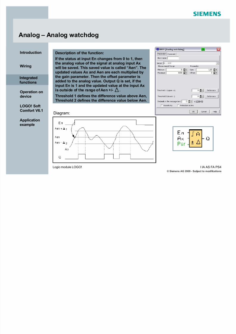
Analog ± Analog watchdog
Description of the function:
If the status at input En changes from 0 to 1, thenthe analog value of the signal at analog input Axwill be saved. This saved value is called ³Aen´. Theupdated values Ax and Aen are each multiplied bythe gain parameter. Then the offset parameter isadded to the analog value. Output Q is set, if the
input En is 1 and the updated value at the input Axis outside of the range of Aen +/- .
Threshold 1 defines the difference value above Aen,Threshold 2 defines the difference value below Aen.
Diagram:
Integrated
functions
1
2

5/12/2018 LOGO! in Details - slidepdf.com
http://slidepdf.com/reader/full/logo-in-details 43/146
© Siemens AG 2009 - Subject to modificationsI IA AS F A PS4Logic module LOGO!
Introduction
Wiring
Integrated
functions
Operation ondevice
LOGO! SoftComfort V6.1
Application
example
Analog ± Analog amplifier
Description of the function:
The function reads the analog value of thesignal at analog input Ax. This value ismultiplied by the gain parameter. Then theoffset parameter is added to the analog value,i.e. (Ax * gain) + offset = updated value Ax.Output AQ shows the updated value Ax.Integrated
functions

5/12/2018 LOGO! in Details - slidepdf.com
http://slidepdf.com/reader/full/logo-in-details 44/146
© Siemens AG 2009 - Subject to modificationsI IA AS F A PS4Logic module LOGO!
Introduction
Wiring
Integrated
functions
Operation ondevice
LOGO! SoftComfort V6.1
Application
example
Analog ± PI controller
Description of the function:
If the input A/M is set to 0, then the special function setsoutput AQ with the value that is set with parameter Mq.
If the input A/M is set to 1, then automatic modecommences. As an integral sum the value Mq isadopted, the controller function begins the calculationsof the formulas.
The updated value PV is used within the formulas.Updated value PV = (PV * gain) + offsetIf the updated value PV = SP, then the function does notchange the value of AQ. With a disturbance, AQcontinues to increase / decrease until the updated valuePV again corresponds to SP. The speed with which AQ
changes depends on the parameters KC and TI. If theinput PV exceeds the parameter Max, then the updatedvalue PV is set to the value of Max. If the PV falls shortof the parameter Min, then the updated value PV is setto the value of Min. If the input R is set to 1, then the AQoutput is reset. As long as R is set, the input A/M isdisabled. The sampling time is fixed at 500 ms.
Integrated
functions

5/12/2018 LOGO! in Details - slidepdf.com
http://slidepdf.com/reader/full/logo-in-details 45/146
© Siemens AG 2009 - Subject to modificationsI IA AS F A PS4Logic module LOGO!
Introduction
Wiring
Integrated
functions
Operation ondevice
LOGO! SoftComfort V6.1
Application
example
Analog ± PI controller
Parameter:
Sensor: Type of sensor usedMin: Minimum value for PV
Max: Maximum value for PVGain: Gain for PVOffset: Zero offset for PVSP: Set point assignmentMq: Value of AQ in manual modeParameter sets: applied presets for KC, TIand Dir
KC: GainTI: Integral timeDir: Action direction of the controller Number of decimal places in message text
Integrated
functions

5/12/2018 LOGO! in Details - slidepdf.com
http://slidepdf.com/reader/full/logo-in-details 46/146
© Siemens AG 2009 - Subject to modificationsI IA AS F A PS4Logic module LOGO!
Introduction
Wiring
Integrated
functions
Operation ondevice
LOGO! SoftComfort V6.1
Application
example
Analog ± PI controller
Parameter sets:
To simplify the use of the PI controller, parameters for KC, TI and Dir are preset assets for the following applications:
Parameters can manually be specified via the parameter set ³User defined´.
Parameter Set ApplicationsParameter
KCParameter
TI (s)Parameter Dir
Temperaturefast
Temperature, low temperature controlfor small rooms; small volumes
0.5 30 +
Temperature
slow
Heater, ventilation, temperature, lowtemperature control for large rooms,
large volumes1.0 120 +
Pressure 1Fast pressure change,
compressor control3.0 5 +
Pressure 2
Slow pressure change,
Differential pressure control
(flow control)
1.2 12 +
Filling level 1Barrel, container filling withoutdownpipe/ drain
1.0 1 +
Filling level 2Barrel, container filling with downpipe/drain
0.7 20 +
Integrated
functions

5/12/2018 LOGO! in Details - slidepdf.com
http://slidepdf.com/reader/full/logo-in-details 47/146
© Siemens AG 2009 - Subject to modificationsI IA AS F A PS4Logic module LOGO!
Introduction
Wiring
Integrated
functions
Operation ondevice
LOGO! SoftComfort V6.1
Application
example
Analog ± Ramp
Description of the function:
At the analog output, this special function starts up one of twolevels or offset. Here you can set how quickly the level shouldbe reached. If the input En is set, then the function issues thevalue StSp + offset at output AQ for the first 100 ms.Then, depending on the connection of Sel, the function runsfrom value StSp + offset to either level 1 or level 2 at the
acceleration set in Rate.If the input St is set, the function runs to the value StSp + offsetat the acceleration set in Rate. Then the function issues the
value StSp + offset at output AQ for 100 ms. Finally offset isissued at output AQ.If the input St is set, the function can only be restarted once theinputs St and En have been reset.If input Sel has been changed, depending on the connection of Sel, the function runs from level 1 to level 2 or the other wayround. If the input En is reset, the function immediately issuesoffset at output AQ. The analog value at the output isrecalculated every 100 ms.
Integrated
functions

5/12/2018 LOGO! in Details - slidepdf.com
http://slidepdf.com/reader/full/logo-in-details 48/146
© Siemens AG 2009 - Subject to modificationsI IA AS F A PS4Logic module LOGO!
Introduction
Wiring
Integrated
functions
Operation ondevice
LOGO! SoftComfort V6.1
Application
example
Analog - Ramp
Parameter:
Gain: Gain for AQ in message textOffset: Zero offset for AQ in message textL1 and L2: Levels to be reached
Largest output value: Maximum value thatmust not be exceeded under anycircumstancesStart/ stop offset: value that is issued for 100ms in addition to parameter offset after starting the function and before reaching the
offset value (prompted by input St). Thisparameter is intended for controlling motors.Speed of change: Acceleration with which level1, level 2 or offset is reached.Steps/ second are input.Number of decimal places in message text
Integrated
functions

5/12/2018 LOGO! in Details - slidepdf.com
http://slidepdf.com/reader/full/logo-in-details 49/146
© Siemens AG 2009 - Subject to modificationsI IA AS F A PS4Logic module LOGO!
Introduction
Wiring
Integrated
functions
Operation ondevice
LOGO! SoftComfort V6.1
Application
example
Analog - Ramp
Diagram:
Integrated
functions
5/12/2018 LOGO! in Details - slidepdf.com
http://slidepdf.com/reader/full/logo-in-details 50/146
© Siemens AG 2009 - Subject to modificationsI IA AS F A PS4Logic module LOGO!
Introduction
Wiring
Integrated
functions
Operation ondevice
LOGO! SoftComfort V6.1
Application
example
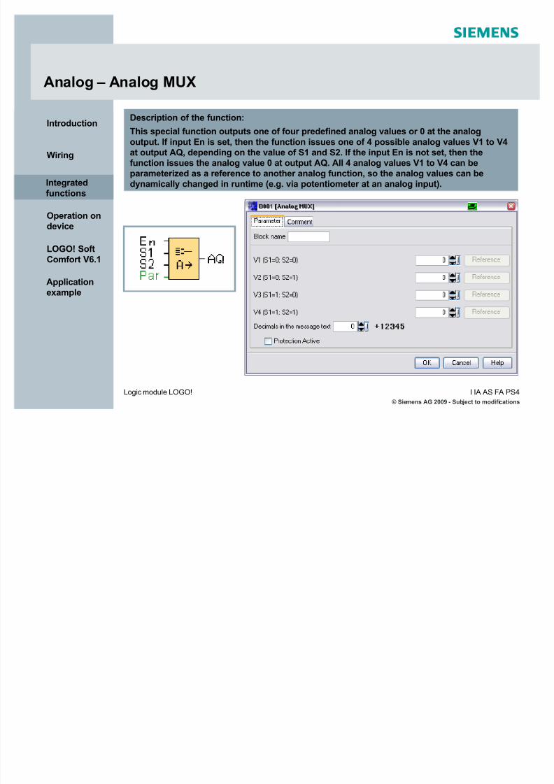
Analog ± Analog MUX
Description of the function:
This special function outputs one of four predefined analog values or 0 at the analog
output. If input En is set, then the function issues one of 4 possible analog values V1 to V4at output AQ, depending on the value of S1 and S2. If the input En is not set, then thefunction issues the analog value 0 at output AQ. All 4 analog values V1 to V4 can beparameterized as a reference to another analog function, so the analog values can bedynamically changed in runtime (e.g. via potentiometer at an analog input).Integrated
functions

5/12/2018 LOGO! in Details - slidepdf.com
http://slidepdf.com/reader/full/logo-in-details 51/146
© Siemens AG 2009 - Subject to modificationsI IA AS F A PS4Logic module LOGO!
Introduction
Wiring
Integrated
functions
Operation ondevice
LOGO! SoftComfort V6.1
Application
example
Analog ± Pulse Width Modulator (PWM)
Description of the function:
The PWM function modulates the analog inputvalue Ax into a pulsed digital output signal. The
pulse width is proportional to the analog value Ax.
The function reads the value of the signal at the
analog input Ax. This value is multiplied by thevalue of parameter A (gain). Parameter B (offset) isadded to the product, as follows:(Ax * Gain) + Offset = Actual value Ax
The function block calculates the proportion of thevalue Ax to the range. The block sets the digitaloutput Q high for the same proportion of the PT(periodic time) parameter, and sets Q low for theremainder of the time period.
Integrated
functions

5/12/2018 LOGO! in Details - slidepdf.com
http://slidepdf.com/reader/full/logo-in-details 52/146
© Siemens AG 2009 - Subject to modificationsI IA AS F A PS4Logic module LOGO!
Introduction
Wiring
Integrated
functions
Operation ondevice
LOGO! SoftComfort V6.1
Application
example
Analog ± Pulse Width Modulator (PWM)
Example 1:
Periodic time (PT) = 4 sec.Ax = 500
1) 500 / (1000-0) = 0,5
2) 4 sec. * 0,5 = 2 sec.
Q = 2 sec. high , 2 sec. low
Example 2:
Periodic time (PT) = 10 sec.Ax = 300
1) 300 / (1000-0) = 0,3
2) 10 sec. * 0,3 = 3 sec.
Q = 3 sec. high , 7 sec. low
Calculation rule :
Q = 1, for Ax / (Max - Min) of time period PT
Q = 0, for PT - [Ax / (Max - Min)] of time period PT
Note: Ax in this calculation refers to the actual value Ax as calculated using the Gain and Offset.
Min and Max refer to the minimum and maximum values specifed for the range.
Integrated
functions

5/12/2018 LOGO! in Details - slidepdf.com
http://slidepdf.com/reader/full/logo-in-details 53/146
© Siemens AG 2009 - Subject to modificationsI IA AS F A PS4Logic module LOGO!
Introduction
Wiring
Integrated
functions
Operation ondevice
LOGO! SoftComfort V6.1
Application
example
Analog - Analog Math
Description of the function:
The function combines four valuesand three operators to form anequation. The operator can be anyone of the four standard operators:+ , - , x , /
For each operator, you must set aunique priority of High ("H"), Medium("M"), or Low ("L").The high operation will be performedfirst, followed by the mediumoperation and the low operation. Theoperand values can referenceanother previously-defined functionto provide the value.
You can also configure the behavior of the function when the Enable
parameter "En"=0.The function block can either retainits last value or be set to 0.
The result is an internal analog value(-32768 - +32767). A result out of this range causes an overflow-error.
Operator /Priority Value 1
Value 2
Value 3
Value 4
Integrated
functions

5/12/2018 LOGO! in Details - slidepdf.com
http://slidepdf.com/reader/full/logo-in-details 54/146
© Siemens AG 2009 - Subject to modificationsI IA AS F A PS4Logic module LOGO!
Introduction
Wiring
Integrated
functions
Operation ondevice
LOGO! SoftComfort V6.1
Application
example
Analog - Analog Math
Integrated
functions
Examples:

5/12/2018 LOGO! in Details - slidepdf.com
http://slidepdf.com/reader/full/logo-in-details 55/146
© Siemens AG 2009 - Subject to modificationsI IA AS F A PS4Logic module LOGO!
Introduction
Wiring
Integrated
functions
Operation ondevice
LOGO! SoftComfort V6.1
Application
example
Miscellaneous - Analog Math Error Detection
Description of the function:
The analog math error detection block sets the output when the referenced analog mathfunction block has an error. You can program the function to set the output on a zerodivision error, an overflow error, or when either type of error occurs.
If you select the ³Automatically reset´ checkbox, the output is reset prior to the nextexecution of the function block. If not, the output retains its state until the analog math error detection block is reset with the R parameter.
Integrated
functions

5/12/2018 LOGO! in Details - slidepdf.com
http://slidepdf.com/reader/full/logo-in-details 56/146
© Siemens AG 2009 - Subject to modificationsI IA AS F A PS4Logic module LOGO!
Introduction
Wiring
Integrated
functions
Operation ondevice
LOGO! SoftComfort V6.1
Application
example
Miscellaneous ± Latching relay
A look at the circuit diagram shows that the coil K1 has currentwith the pushbutton S1. The switch K1 closes (latch).
This function is called latching relay.
Symbol for this connection is .S2
K1 M
S1 K1 K1
K2
Description of the function:
Input S sets output Q, input R resets output Q again.
S
R
Q
Diagram:
Integrated
functions

5/12/2018 LOGO! in Details - slidepdf.com
http://slidepdf.com/reader/full/logo-in-details 57/146
© Siemens AG 2009 - Subject to modificationsI IA AS F A PS4Logic module LOGO!
Introduction
Wiring
Integrated
functions
Operation ondevice
LOGO! SoftComfort V6.1
Application
example
Miscellaneous ± Pulse relay
Description of the function:
Output Q changes its status, i.e. the output is set or reset, with each 0 to 1 transition atinput Trg. You reset the pulse relay to 0 with a signal at input R.
A look at the circuit diagram shows that the light H1 is switchedon and off with the pushbuttons S1 or S2.
This function is called pulse relay.
In words a short pulse at S1 or S2 switches the light H1 on andoff.
Symbol for this connection is .K1
S1 K1S2
H1
Trg
R
Q
Diagram:
Integrated
functions

5/12/2018 LOGO! in Details - slidepdf.com
http://slidepdf.com/reader/full/logo-in-details 58/146
© Siemens AG 2009 - Subject to modificationsI IA AS F A PS4Logic module LOGO!
Introduction
Wiring
Integrated
functions
Operation ondevice
LOGO! SoftComfort V6.1
Application
example
Miscellaneous ± Message text
Features:
Only one programming tool for basicmodule and LOGO! TD
Selection / enabling of different
character sets
Up to 24/32 characters per line(depending on selected character set)
Ticker text
Selection of message destination
Bar graph functionality
Display state of analog input values
Digital I/O states
Display of remaining time of all
timers (except weekly/yearly timer)
Integrated
functions

5/12/2018 LOGO! in Details - slidepdf.com
http://slidepdf.com/reader/full/logo-in-details 59/146
© Siemens AG 2009 - Subject to modificationsI IA AS F A PS4Logic module LOGO!
Introduction
Wiring
Integrated
functions
Operation ondevice
LOGO! SoftComfort V6.1
Application
example
Display of a configured message text in runmode.
Symbol for this function is .
Miscellaneous ± Message text
Description of the function:
With a 0 to 1 transition of the input signal andwhen the system is in RUN, the correspondingmessage text is output to the display. Themessage text is hidden when the status of the
signal at input changes from 1 to 0. Whenmultiple message text functions are triggeredwith En=1, the message text that has the highest
priority is shown. Changing between thestandard display and the message texts displayis possible by using the keys and . If ³acknowledge message´ is chosen, therespective message text will be hidden bypressing any key on LOGO!, if En=0.
LOGOOK
1234
Motor on
ESC
I :
0.. 123456789
1..0123456789
2..01234
Alarm!Current Temp
97 °C
s
Integrated
functions

5/12/2018 LOGO! in Details - slidepdf.com
http://slidepdf.com/reader/full/logo-in-details 60/146
© Siemens AG 2009 - Subject to modificationsI IA AS F A PS4Logic module LOGO!
Introduction
Wiring
Integrated
functions
Operation ondevice
LOGO! SoftComfort V6.1
Application
example
Miscellaneous ± Message textSelection/enabling of character sets
LOGO! ..0BA6 supports several languages.
To ensure, that all characters of a language
used in a message text can be displayedcorrectly, it is necessary to activate anaccordant character set.
ISO_8859_1German, English, Italian, Spanish(partly), Dutch (partly)
ISO_8859_5 Russian
ISO_8859_9 Turkish
ISO_8859_16 French
GBK Chinese
SJIS *) Japanese (partly)
6 character sets are available *)
To be able to use all features of themessage text function in LOGO! ..0BA6,³Use new feature´ must be enabled(Fil e -> Message text sett ings).
Integrated
functions
*) since E-Stand 3 (ES3)

5/12/2018 LOGO! in Details - slidepdf.com
http://slidepdf.com/reader/full/logo-in-details 61/146
© Siemens AG 2009 - Subject to modificationsI IA AS F A PS4Logic module LOGO!
Introduction
Wiring
Integrated
functions
Operation ondevice
LOGO! SoftComfort V6.1
Application
example
Miscellaneous ± Message textSelection/enabling of character sets
In the samemessage text 2
different character sets can beselected.
By using the FlagM27 character set1 or character set2 gets activated.
Integrated
functions
Character set 1
(e.g. ISO_8859_1)
Character set 2
(e.g. GBK)

5/12/2018 LOGO! in Details - slidepdf.com
http://slidepdf.com/reader/full/logo-in-details 62/146
© Siemens AG 2009 - Subject to modificationsI IA AS F A PS4Logic module LOGO!
Introduction
Wiring
Integrated
functions
Operation ondevice
LOGO! SoftComfort V6.1
Application
example
Character by character «(one character after another tickers through the display)
« or Line by line.
(the display alternates between the 1st half and the2nd half of the message text)
1st half 2nd half
Miscellaneous ± Message textSettings for the ticker text
Integrated
functions
For the LOGO! on-board display and for LOGO! TD ticker text can be used.
You can ticker the text in 2 ways:
Character by character or
Line by line
In the function blockmessage text you can choose³Character by character´ or ³Line by line´ and enable oneor more lines which shall betickered.

5/12/2018 LOGO! in Details - slidepdf.com
http://slidepdf.com/reader/full/logo-in-details 63/146
© Siemens AG 2009 - Subject to modificationsI IA AS F A PS4Logic module LOGO!
Introduction
Wiring
Integrated
functions
Operation ondevice
LOGO! SoftComfort V6.1
Application
example
The ticker speed can be adjusted via the menu item Fil e -> Message Text Sett ings -> T i cker
T imer Sett ing .
You can set the speed for ³Character by character´ in milliseconds. This time has alsoeffect to the time for ³Line by line´ (Character by character x10).
Miscellaneous ± Message textSettings for the ticker text
Integrated
functions
³Message destination´ is another properties parameter in the functionblock message text:
Here you can decide, on which devicethe message text shall appear:
LOGO! on-board display
LOGO! TD
Both displays

5/12/2018 LOGO! in Details - slidepdf.com
http://slidepdf.com/reader/full/logo-in-details 64/146
© Siemens AG 2009 - Subject to modificationsI IA AS F A PS4Logic module LOGO!
Introduction
Wiring
Integrated
functions
Operation ondevice
LOGO! SoftComfort V6.1
Application
example
Miscellaneous ± Message textInserting bar graphs
Step 1: Click at
ÄInsert a bar graph into the message³
Step 2: Select a function block which
is already placed in the circuitdiagram to indicate its value.
Step 3: Scale the bar graph by defining
the range of the value, bar graph size
and its direction on the display.
The vertical adjustment of thebar graph is from the bottom
to the top !
Integrated
functions
Example 1:

5/12/2018 LOGO! in Details - slidepdf.com
http://slidepdf.com/reader/full/logo-in-details 65/146
© Siemens AG 2009 - Subject to modificationsI IA AS F A PS4Logic module LOGO!
Introduction
Wiring
Integrated
functions
Operation ondevice
LOGO! SoftComfort V6.1
Application
example
Miscellaneous ± Message textInserting bar graphs
The horizontal adjustment of the bar graph is from left to right !
Example 2:
The analog value of a temperaturesensor (PT100) is to be indicated over its entire measuring range as bar graph horizontally in the messagetext.
Integrated
functions

5/12/2018 LOGO! in Details - slidepdf.com
http://slidepdf.com/reader/full/logo-in-details 66/146
© Siemens AG 2009 - Subject to modificationsI IA AS F A PS4Logic module LOGO!
Introduction
Wiring
Integrated
functions
Operation ondevice
LOGO! SoftComfort V6.1
Applicationexample
Miscellaneous ± Message textStatus indication of the analog input values
2 analog input values (AI)can be displayed in onemessage text if they areused in the circuit diagram.
The value is updatedaccording to the ³analoginput filter timer´.Integrated
functions

5/12/2018 LOGO! in Details - slidepdf.com
http://slidepdf.com/reader/full/logo-in-details 67/146
© Siemens AG 2009 - Subject to modificationsI IA AS F A PS4Logic module LOGO!
Introduction
Wiring
Integrated
functions
Operation ondevice
LOGO! SoftComfort V6.1
Applicationexample
Miscellaneous ± Message textAnalog input filter timer
If an analog input value is indicated in a
message text, via the menu item
Fil e -> Message Text Sett ings can bedefined, how often LOGO! refreshes theanalog values in a message text.
Integrated
functions

5/12/2018 LOGO! in Details - slidepdf.com
http://slidepdf.com/reader/full/logo-in-details 68/146
© Siemens AG 2009 - Subject to modificationsI IA AS F A PS4Logic module LOGO!
Introduction
Wiring
Integrated
functions
Operation ondevice
LOGO! SoftComfort V6.1
Applicationexample
Miscellaneous ± Message textStatus indication of the digital inputs/outputs
Step 1:
Place 1 input, 1 output and an enabledmessage text in your circuit diagram.
Step 2:
Open message text with a double click,
define area for the status indication of ³I1´ with a mouse click and select³ON/OFF´ button.
Example:Integrated
functions
You can assign names such as "On" or "Off" to the two states of a digital input or output.With the LOGO! 0BA6 series, you can display this name of a digital I/O state in a messagetext.

5/12/2018 LOGO! in Details - slidepdf.com
http://slidepdf.com/reader/full/logo-in-details 69/146
© Siemens AG 2009 - Subject to modificationsI IA AS F A PS4Logic module LOGO!
Introduction
Wiring
Integrated
functions
Operation ondevice
LOGO! SoftComfort V6.1
Applicationexample
Miscellaneous ± Message textStatus indication of the digital inputs/outputs
Step 3:
Select ³Digital Inputs´
Step 4:
Automatically the first input ³I1´ isselected.Type in a text you want to display for bothstates of ³I1´.
Integrated
functions

5/12/2018 LOGO! in Details - slidepdf.com
http://slidepdf.com/reader/full/logo-in-details 70/146
© Siemens AG 2009 - Subject to modificationsI IA AS F A PS4Logic module LOGO!
Introduction
Wiring
Integrated
functions
Operation ondevice
LOGO! SoftComfort V6.1
Applicationexample
Miscellaneous ± Message textStatus indication of the digital inputs/outputs
Step 5:
Do the same for ³Digital Outputs´ anddisplay the state of ³Q1´.
Now try out the program in simulation mode!
Integrated
functions

5/12/2018 LOGO! in Details - slidepdf.com
http://slidepdf.com/reader/full/logo-in-details 71/146
© Siemens AG 2009 - Subject to modificationsI IA AS F A PS4Logic module LOGO!
Introduction
Wiring
Integrated
functions
Operation ondevice
LOGO! SoftComfort V6.1
Applicationexample
Miscellaneous ± Message textStatic editor (Edit manually)
LOGO! Soft Comfort V6.1 provides a staticeditor for message texts that can help when youneed to reposition text elements.
For example, it has a ³recycle bin´ area whereyou can temporarily move message textelements in order to rearrange the position of elements on the display area. You can move
elements up, down, left, or right withoutchanging the position of any other elements.
To use the static editor, click the "Ed i t
manu ally " button. You will also be prompted toedit manually if you try to place or moveelements in the message area that have aposition conflict with existing elements.
Integrated
functions

5/12/2018 LOGO! in Details - slidepdf.com
http://slidepdf.com/reader/full/logo-in-details 72/146
© Siemens AG 2009 - Subject to modificationsI IA AS F A PS4Logic module LOGO!
Introduction
Wiring
Integrated
functions
Operation ondevice
LOGO! SoftComfort V6.1
Applicationexample
Miscellaneous ± Softkey
Diagram:Description of the function:
This special function has the effect of amechanical pushbutton or switch. In parameter assignment mode, the output is set with a signal
at input En, if the ¶¶Switch´ parameter is set to³On´ and confirmed with OK. Whether thefunction was configured for pushbutton or switching action is of no concern here. Theoutput is reset to ³0´ in the following threecases:
After a 0 to 1 transition at input En.
When the function was configured for momentary pushbutton action, and onecycle has expired since it was switched on.
When the position ³Off´ was selected at the³Switch´ parameter and confirmed with OKin parameter assignment mode.
Integrated
functions

5/12/2018 LOGO! in Details - slidepdf.com
http://slidepdf.com/reader/full/logo-in-details 73/146
© Siemens AG 2009 - Subject to modificationsI IA AS F A PS4Logic module LOGO!
Introduction
Wiring
Integrated
functions
Operation ondevice
LOGO! SoftComfort V6.1
Applicationexample
Miscellaneous ± Shift register
Description of the function:
The function reads the value at input In with apositive edge at input Trg. This value isapplied to shift register bit S1 to S8,depending on the shifting direction:
Shift up: The value at input In is set at S1; theprevious value at S1 is shifted to S2; the
previous value at S2 is shifted to S3 etc.Output Q returns the value of the configuredshift register bit. If retentivity is disabled, theshift function restarts at S1 to S8 after a
power failure. When enabled, retentivityalways applies to all shift register bits.
Diagram:
Shiftup
Shiftdown
S4 = Q (example)
Integrated
functions

5/12/2018 LOGO! in Details - slidepdf.com
http://slidepdf.com/reader/full/logo-in-details 74/146
© Siemens AG 2009 - Subject to modificationsI IA AS F A PS4Logic module LOGO!
Introduction
Wiring
Integrated
functions
Operation ondevice
LOGO! SoftComfort V6.1
Applicationexample
Operation on device
Connect LOGO! to the power supply andswitch it on. The display now shows youthis message.
Press to get to the main menu.
Have you designed a circuit?Do you want to enter it into LOGO! ?How do you do this?
LOGO!
No ProgramPress ESC
OKESC
s
LOGO!
> Program..
Card..
Setup..
StartOKESC
s
Operation ondevice
ESC

5/12/2018 LOGO! in Details - slidepdf.com
http://slidepdf.com/reader/full/logo-in-details 75/146
© Siemens AG 2009 - Subject to modifications
I IA
AS
F A
PS4L
ogic moduleLOGO!
Introduction
Wiring
Integrated
functions
Operation ondevice
LOGO! SoftComfort V6.1
Applicationexample
> Program..
Card..Setup..
StartOKESC
s
LOGO!
> Edit..
Clear Prg
Password
Msg ConfigOKESC
s
Main menu / programming menu
Here you can also move the ´>´ cursor by pressing .
Move the ´>´ cursor to ´Ed i t ..´ and confirm with .In the next sub-menu please chose ³Ed i t Prg .´ You arenow in programming menu.
OK
Press to select all output, marker and openconnectors.
The following applies when you edit a circuit: ....
The first character in the first line is the ´>´ cursor.Press to move the ´>´ cursor up and down.
Move it to ³Program..´ and confirm with .
LOGO! opens the programming menu.
OK
LOGO!
> Edit Prg
Edit Name
AQ
Memory? OKESC
s
LOGO!
LOGO!OKESC
B1 Q1
s
Operation ondevice

5/12/2018 LOGO! in Details - slidepdf.com
http://slidepdf.com/reader/full/logo-in-details 76/146
© Siemens AG 2009 - Subject to modifications
I IA
AS
F A
PS4L
ogic moduleLOGO!
Introduction
Wiring
Integrated
functions
Operation ondevice
LOGO! SoftComfort V6.1
Applicationexample
LOGO! - rules for operation
I
I1
Q
Q1
Q
Q1
&
B001
Q
Q2
&
B002
1. You have to create your circuit by working from theoutput to the input.
2. You can connect an outputto several inputs.
3. You can¶t connect an output toan upstream input within thesame path (recursion).
B002
>
&
B002
Operation ondevice

5/12/2018 LOGO! in Details - slidepdf.com
http://slidepdf.com/reader/full/logo-in-details 77/146
© Siemens AG 2009 - Subject to modifications
I IA
AS
F A
PS4L
ogic moduleLOGO!
Introduction
Wiring
Integrated
functions
Operation ondevice
LOGO! SoftComfort V6.1
Applicationexample
4. You can move the cursor with if it appears in the form of anunderscore ( _ ) :
LOGO! - rules for operation
Q1B01Q1B01Q1
B02B01
I1
x
&Q1
B02B01
I1
x
&B01
B02
I31
xx
Operation ondevice

5/12/2018 LOGO! in Details - slidepdf.com
http://slidepdf.com/reader/full/logo-in-details 78/146
© Siemens AG 2009 - Subject to modifications
I IA
AS
F A
PS4L
ogic moduleLOGO!
Introduction
Wiring
Integrated
functions
Operation ondevice
LOGO! SoftComfort V6.1
Applicationexample
LOGO! - rules for operation
Confirm with .
Press to return to theprevious step.
OK
ESC
OK
Q1GF
Q1SF
Q1Co
>1
Q1
B1
&
5. When the cursor appears as a solid square ( ), press withto select a connector (Co), a basic function (GF) or a special function:
OKOKOK
In1In2
In3In4
Q1
B1
&In1In2
In3
In4
Q1
B1In1In2
In3
In4
Q1
B1
&In1In2
In3In4
Q1
B1
&CoIn2
In3
In4
Q1
B1
&I1
In2
In3
In4
Q1
B1
&I2
In2
In3
In4
Operation ondevice

5/12/2018 LOGO! in Details - slidepdf.com
http://slidepdf.com/reader/full/logo-in-details 79/146
© Siemens AG 2009 - Subject to modifications
I IA
AS
F A
PS4L
ogic moduleLOGO!
Introduction
Wiring
Integrated
functions
Operation ondevice
LOGO! SoftComfort V6.1
Applicationexample
LOGO! interprets the parallel circuit of
S1 and S2 as an ¶OR¶ logic, because S1
or S2 switches on the output.
Your first LOGO! program
The load is switched on with S1 or S2.
Let us now take a look at the following parallel circuit consisting of two switches.
>1I1I2
X
Q1
Solution with LOGO!
X
S1 S2
K1
K1
E1
Circuit diagram
Operation ondevice

5/12/2018 LOGO! in Details - slidepdf.com
http://slidepdf.com/reader/full/logo-in-details 80/146
© Siemens AG 2009 - Subject to modifications
I IA
AS
F A
PS4L
ogic moduleLOGO!
Introduction
Wiring
Integrated
functions
Operation ondevice
LOGO! SoftComfort V6.1
Applicationexample
Wiring
S1 switches input I1, while S2 switchesinput I2. The load (E1) isconnected to the relay Q1.
Let us now input the program (starting atthe output and working towards theinput). LOGO! initially shows the outputQ1. You will see an underscore ( _ )below the Q in Q1. It is called a cursor.The cursor indicates your current
position in the program.
L1
N
S1
LOGO! 230RC
OK
Q1
I1 I2 I3 I4 I5 I6L1 N
Q1 Q2 Q3 Q4
S2
L1
N
I7 I8
ESC
E1
Operation ondevice s

5/12/2018 LOGO! in Details - slidepdf.com
http://slidepdf.com/reader/full/logo-in-details 81/146
© Siemens AG 2009 - Subject to modifications
I IA
AS
F A
PS4L
ogic moduleLOGO!
Introduction
Wiring
Integrated
functions
Operation ondevice
LOGO! SoftComfort V6.1
Applicationexample
Program input
Now press the key .The cursor moves to the left.
The cursor indicates your current
position in the program. At this point youonly enter the first block (the OR block).
Press to select editing mode.
The cursor is displayed as a solid square( ):
Selected between the following bypressing :
Connector (Co)
Basic function (GF)
Special function (SF)
OK
LOGO!OKESC
Q1
LOGO!OKESC
Q1
LOGO!OKESC
Co Q1
Operation ondevice
s
s
s

5/12/2018 LOGO! in Details - slidepdf.com
http://slidepdf.com/reader/full/logo-in-details 82/146
© Siemens AG 2009 - Subject to modifications
I IA
AS
F A
PS4L
ogic moduleLOGO!
Introduction
Wiring
Integrated
functions
Operation ondevice
LOGO! SoftComfort V6.1
Applicationexample
Select with (GF) the basic functions andconfirm with .
Program input
The AND is the first block of the basicfunctions (GF) list.
You can choose between the following bypressing : AND AND (edge) NAND NAND (edge) OR NOR XOR NOT
Select the OR block ( >1 ) and confirm with.
OK
OK
Operation ondevice
LOGO!OKESC
GF Q1
s
LOGO!OKESC
Q1
B1
>1In1In2In3In4
s
LOGO!OKESC
Q1
B1
>1In1In2In3In4
s

5/12/2018 LOGO! in Details - slidepdf.com
http://slidepdf.com/reader/full/logo-in-details 83/146
© Siemens AG 2009 - Subject to modifications
I IA
AS
F A
PS4L
ogic moduleLOGO!
Introduction
Wiring
Integrated
functions
Operation ondevice
LOGO! SoftComfort V6.1
Applicationexample
Program input
You have now entered the first block. Eachnew block is automatically assigned a
block number (B1). Now you interconnectthe block inputs (B1).
Press .
The cursor is displayed as a solid square( ):
You can choose between the following bypressing : Connector (Co) Basic functions (GF) Special functions (SF)
Please select Connector (Co) and confirm
with .The first element of the list (Co) is input I1Confirm with . The underscore cursor automatically jumps to the next input (In2)that needs to be allocated.
.
OK
OK
OK
Operation ondevice
LOGO!OKESC
Q1
B1
>1CoIn2In3In4
s
LOGO!OKESC
Q1
B1
>1I1
In2In3In4
s
LOGO!OKESC
Q1
B1
>1I1
In2In3In4
s
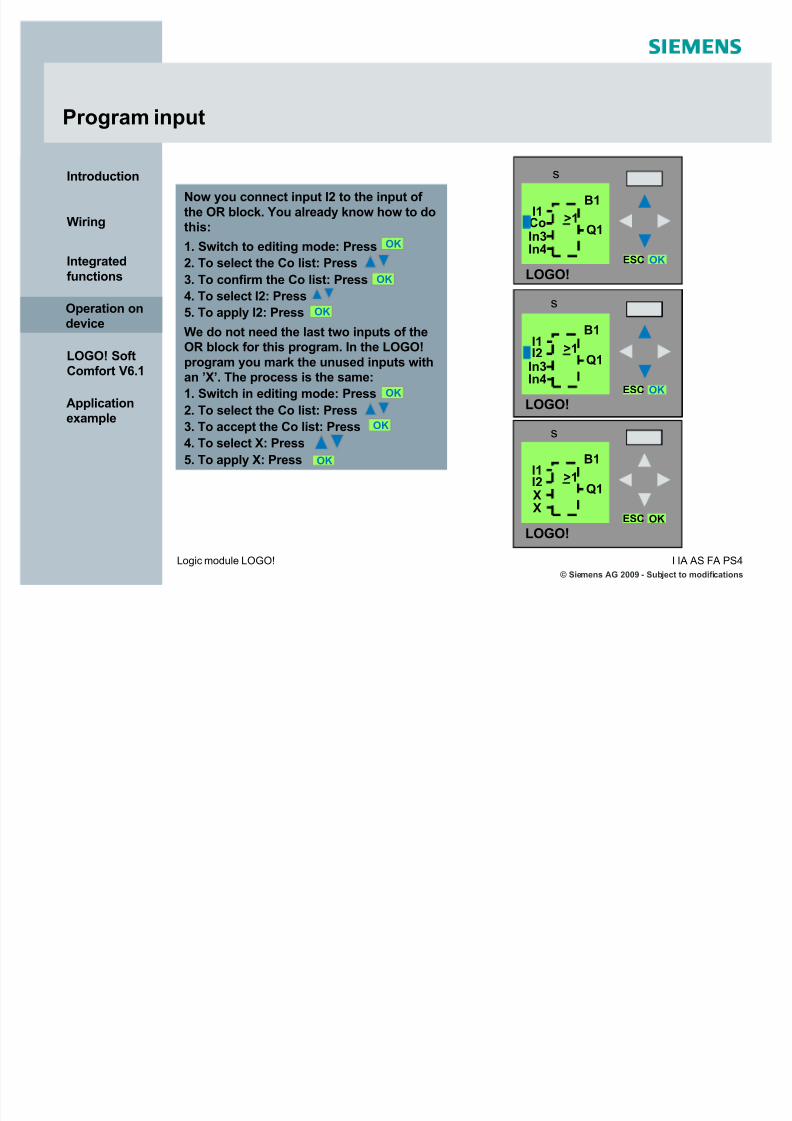
5/12/2018 LOGO! in Details - slidepdf.com
http://slidepdf.com/reader/full/logo-in-details 84/146
© Siemens AG 2009 - Subject to modifications
I IA AS F A PS4Logic module LOGO!
Introduction
Wiring
Integrated
functions
Operation ondevice
LOGO! SoftComfort V6.1
Applicationexample
Program input
Now you connect input I2 to the input of
the OR block. You already know how to dothis:
1. Switch to editing mode: Press
2. To select the Co list: Press
3. To confirm the Co list: Press
4. To select I2: Press
5. To apply I2: Press
We do not need the last two inputs of theOR block for this program. In the LOGO!
program you mark the unused inputs withan ¶X¶. The process is the same:
1. Switch in editing mode: Press
2. To select the Co list: Press
3. To accept the Co list: Press4. To select X: Press
5. To apply X: Press
OK
OK
OK
LOGO!OKESC
Q1
B1
>1I1I2XX
OK
OK
OK
LOGO!OKESC
Q1
B1
>1I1CoIn3In4
s
LOGO!OKESC
Q1
B1
>1I1I2
In3In4
s
s
Operation ondevice

5/12/2018 LOGO! in Details - slidepdf.com
http://slidepdf.com/reader/full/logo-in-details 85/146
© Siemens AG 2009 - Subject to modifications
I IA AS F A PS4Logic module LOGO!
Introduction
Wiring
Integrated
functions
Operation ondevice
LOGO! SoftComfort V6.1
Applicationexample
Program start
Now all block inputs are connected. For LOGO! the program is complete.
You can review your first program by
pressing the cursor with the 4 arrow keys( _ ) and moving through the program.
We now exit program input mode andreturn to the programming menu with .The program is automatically saved in theinternal memory (E2PROM).
To start the program, return to the mainmenu with .
Move the cursor to ³Start´: Press . Toconfirm press .
ESC
ESC
OK
LOGO!OKESC
Q1
B1
>1
I1
I2XX
LOGO!
LOGO!
> Edit Prg
Edit Name
AQ
Memory? OKESC
> Edit..
Clear Prg
Password
Msg Config OKESC
LOGO!
Program..
Card..
Setup..
> StartOKESC
s
Operation ondevice
s
s
s

5/12/2018 LOGO! in Details - slidepdf.com
http://slidepdf.com/reader/full/logo-in-details 86/146
© Siemens AG 2009 - Subject to modifications
I IA AS F A PS4Logic module LOGO!
Introduction
Wiring
Integrated
functions
Operation ondevice
LOGO! SoftComfort V6.1
Applicationexample
LOGO! in RUN mode
In RUN mode LOGO! shows thefollowing display:
1
1
11
Let us have a look at our example:
When switch S1 is closed, input I1 is supplied with voltage and the status at input I1 is ³1´.LOGO! program calculates the status for the outputs.Output Q1 is ³1´, in this case.When Q1 is ³1´, LOGO! sets relay Q1, and the load connected to Q1 is supplied withvoltage.
The window to the left displays time and date.
The window in the middle displays the inputsstates (I1 to I9; I10 to I19; I20 to I24).
The window to the right displays outputsstates (Q1 to Q9; Q10 to Q16).
Also the internal values of all analoginputs/outputs can be displayed.
Status of inputs
Input I status is Ä1³
Input I status is Ä0³
Status of outputs
Output Q status is Ä1³
Output Q status is Ä0³Operation ondevice
L1
S1=1
S2=0
I :0.. 23456789
1.. 01234567892.. 01234
N
Q1
=1
Tu 09:142009-09-22
Q :0.. 23456789
1..0123456
11
AI :

5/12/2018 LOGO! in Details - slidepdf.com
http://slidepdf.com/reader/full/logo-in-details 87/146
© Siemens AG 2009 - Subject to modifications
I IA AS F A PS4Logic module LOGO!
Introduction
Wiring
Integrated
functions
Operation ondevice
LOGO! SoftComfort V6.1
Applicationexample
LOGO! parameterization mode
Parameterization of functions:
When speaking of parameterization, we refer to theconfiguration of functions. You can configure the parameters
in programming mode
or
in parameter assignmentmode
You can configure:
the delay times of timer functions
the switching times of timer switch
counter thresholds
the monitoring interval for a hour counter
on and off threshold for a trigger threshold
and some other functions
To get to configuration mode pressin RUN mode, set the cursor to Set Paramand confirm with .
ESC
OK
Operation ondevice
LOGO! 12/24 RC
LOGO!
OKESC
I :
0.. 123456789
1..0123456789
2..01234
s
LOGO! 12/24 RC
LOGO!
OKESC
Stop
Set ParamSet..
Prg Name
>
s

5/12/2018 LOGO! in Details - slidepdf.com
http://slidepdf.com/reader/full/logo-in-details 88/146
© Siemens AG 2009 - Subject to modifications
I IA AS F A PS4Logic module LOGO!
Introduction
Wiring
Integrated
functions
Operation ondevice
LOGO! SoftComfort V6.1
Applicationexample
LOGO! parameterization mode
Block selection:
Choose In parameterization mode the desiredblock with .
If the desired block is chosen, press . Thecursor jumps to the first parameter that can bemodified. The value can be changed pressing thearrow keys .
If the desired value is configured, then press .The next blocks requiring modification, can bechosen with etc..
OK
OK
Operation ondevice
LOGO!
B2
T =10:00s
Ta =00:00
OKESC
s
B2
T =15:00s
Ta =00:00
OKESC
LOGO!
s
B2
T =15:00s
Ta =00:00
OKESC
LOGO!
s

5/12/2018 LOGO! in Details - slidepdf.com
http://slidepdf.com/reader/full/logo-in-details 89/146
© Siemens AG 2009 - Subject to modifications
I IA AS F A PS4Logic module LOGO!
Introduction
Wiring
Integrated
functions
Operation ondevice
LOGO! SoftComfort V6.1
Applicationexample
To return to RUN mode press .
LOGO! parameterization mode
To return to menu press .ESC
ESC
LOGO!
LOGO!
LOGO!
B2
T =10:00s
Ta =00:00
OKESC
> Stop
Set Param
Set..
Prg NameOKESC
LOGO!
Operation ondevice
s
s
I :0.. 1234567891..01234567892..01234
OKESC
LOGO!
s

5/12/2018 LOGO! in Details - slidepdf.com
http://slidepdf.com/reader/full/logo-in-details 90/146
© Siemens AG 2009 - Subject to modifications
I IA AS F A PS4Logic module LOGO!
Introduction
Wiring
Integrated
functions
Operation ondevice
LOGO! SoftComfort V6.1
Applicationexample
LOGO! ..0BA6 ± setting the menu language
You can select the menu language via theLOGO! menu and acknowledge with(LOGO! must be in Stop-mode).
Available languages:
EN ± English IT ± Italian NL ± Dutch ES ± Spanish FR ± French CN ± Chinese DE ± German TR ± Turkish RU ± Russian JP ± Japanese *)
LOGO!
Clock..
LCD..
> Menu Lang
BM AI NUM
s
OKESC
LOGO!
Program..
Card..
> Setup..
Start
s
OKESC
Operation ondevice
This setting can be separately done for LOGO! TD .
LOGO!
s
OKESC
> EN
OK
*) since E-Stand 3 (ES3)

5/12/2018 LOGO! in Details - slidepdf.com
http://slidepdf.com/reader/full/logo-in-details 91/146
© Siemens AG 2009 - Subject to modifications
I IA AS F A PS4Logic module LOGO!
Introduction
Wiring
Integrated
functions
Operation ondevice
LOGO! SoftComfort V6.1
Applicationexample
LOGO! ..0BA6 ± backlight function
Backlight function for the basic module:
To activate the backlight of the
LOGO! display permanently, follow
these steps.
You can select between:
Default (Backlight is ON for 20 sec.
or controlled by user program)
Always On
LOGO!
> Default
s
OKESC
LOGO!
Contrast
> BackLight
s
OKESC
LOGO!
Clock..
> LCD..
Menu Lang
BM AI NUM
s
OKESC
LOGO!
Program..
Card..> Setup..
Start
s
OKESC
Operation ondevice
This setting can be separately done for LOGO! TD .

5/12/2018 LOGO! in Details - slidepdf.com
http://slidepdf.com/reader/full/logo-in-details 92/146
© Siemens AG 2009 - Subject to modifications
I IA AS F A PS4Logic module LOGO!
Introduction
Wiring
Integrated
functions
Operation ondevice
LOGO! SoftComfort V6.1
Applicationexample
LOGO! TD parameterization mode
In the menu of LOGO! TD nearly the same menu items are available as in themenu of LOGO! basic module - except the possibility to edit the program.
Operation ondevice
> Stop
Set Param
Msg Config
Set..
The following table shows on which devicewhich menu items are available «
Menu item LOGO! Basic module LOGO! TD
In STOP mode
Program.. ¥ -
Card.. ¥ -
Setup.. ¥ ¥
LCD Contrast / Backlight ¥ ¥
Menu language ¥ ¥
2 or 4 AI used on basic module ¥ -
Start / Stop ¥ ¥ *)
In RUN mode
Set Param ¥ ¥
Msg Config (e.g. Tick Time) - ¥
*) Since E-Stand 4 (ES4) of LOGO! and LOGO! TD, switching into stop mode can be protected by password.

5/12/2018 LOGO! in Details - slidepdf.com
http://slidepdf.com/reader/full/logo-in-details 93/146
© Siemens AG 2009 - Subject to modifications
I IA AS F A PS4Logic module LOGO!
Introduction
Wiring
Integrated
functions
Operation ondevice
LOGO! SoftComfort V6.1
Applicationexample
LOGO! program creationon a PC with LOGO! Soft Comfort V6.1
Support for LOGO! TD No separate software necessary
Modem wizard for standard 11-bit analog modems
Windows Look and Feel e.g. context menu, toolbar
Create the control programs by Ädrag and drop³ Control programs Ädrawing³ ±
directly on a PC in FBD or LAD
Testing of control programs Offline simulation with status for each function
(color change) and forcing
Online test in FBD and LAD with color change
for each function and 30 actual values
Professional print and documentation functions
Device selection 0B A0, 0B A1, 0B A2, 0B A3, 0B A4, 0B A5, 0B A6
with function check
Additionally on the CD ROM:
Manual and 28 complete, usable examples
LOGO! SoftComfort V6.1

5/12/2018 LOGO! in Details - slidepdf.com
http://slidepdf.com/reader/full/logo-in-details 94/146
© Siemens AG 2009 - Subject to modifications
I IA AS F A PS4Logic module LOGO!
Introduction
Wiring
Integrated
functions
Operation ondevice
LOGO! SoftComfort V6.1
Applicationexample
Installing LOGO! Soft Comfort V6.1
1. Insert CD (LOGO! Soft Comfort V6.1) in CD-ROM drive2. Display CD content with help of Explorer 3. Double click on start.html
2.
LOGO! SoftComfort V6.1
3.

5/12/2018 LOGO! in Details - slidepdf.com
http://slidepdf.com/reader/full/logo-in-details 95/146
© Siemens AG 2009 - Subject to modifications
I IA AS F A PS4Logic module LOGO!
Introduction
Wiring
Integrated
functions
Operation ondevice
LOGO! SoftComfort V6.1
Applicationexample
Installing LOGO! Soft Comfort V6.1
LOGO! SoftComfort V6.1
Start.html functions
Direct choice of 10 languages Software installation Direct start of software from CD-ROM Display manuals on CD-ROM Display online help Choice of example programs on CD-ROM Choice of CAD drawings on CD-ROM Installation of necessary tools such as
Acrobat Reader or printer drivers

5/12/2018 LOGO! in Details - slidepdf.com
http://slidepdf.com/reader/full/logo-in-details 96/146
© Siemens AG 2009 - Subject to modifications
I IA AS F A PS4Logic module LOGO!
Introduction
Wiring
Integrated
functions
Operation ondevice
LOGO! SoftComfort V6.1
Applicationexample
Installing LOGO! Soft Comfort V6.1
LOGO! SoftComfort V6.1
The USB cable driver for the LOGO! USB programming cable is also included on theCD-ROM. During the installation process of LSC V6.1 you will be asked if you want to installthe driver.
HINT: Follow the correct order !1. Install the driver (administrator privileges are required!)2. Then connect the LOGO! USB programming cable with your PC

5/12/2018 LOGO! in Details - slidepdf.com
http://slidepdf.com/reader/full/logo-in-details 97/146
© Siemens AG 2009 - Subject to modifications
I IA AS F A PS4Logic module LOGO!
Introduction
Wiring
Integrated
functions
Operation ondevice
LOGO! SoftComfort V6.1
Applicationexample
LOGO! Soft Comfort V6.1 : Overview
Title bar
Menu bar
Symbol bar for program installation
Switch to selecting mode
Text fields for additionalcomments
For a better overviewseparation of connections
Drawing of connection lines
Display connectors (Co)
Display basic functions (GF)
Display special functions (SF)
Offline simulation
Standard Windows PC -> LOGO! LOGO! -> PC!
Control program generation in the overview control plan via drag & drop
Online test
Tree structure for fast choiceof all generation elements
LOGO! SoftComfort V6.1

5/12/2018 LOGO! in Details - slidepdf.com
http://slidepdf.com/reader/full/logo-in-details 98/146
© Siemens AG 2009 - Subject to modifications
I IA AS F A PS4Logic module LOGO!
Introduction
Wiring
Integrated
functions
Operation ondevice
LOGO! SoftComfort V6.1
Applicationexample
Help functions ± online help
With a mouse click on thedesired topic you get detailedinformation about thecorresponding functionalgroup.
The general help can be activatedvia the menu item H elp ->
Content . You can find further
information sorted by functionalgroups in the contents.
LOGO! SoftComfort V6.1

5/12/2018 LOGO! in Details - slidepdf.com
http://slidepdf.com/reader/full/logo-in-details 99/146
© Siemens AG 2009 - Subject to modifications
I IA AS F A PS4Logic module LOGO!
Introduction
Wiring
Integrated
functions
Operation ondevice
LOGO! SoftComfort V6.1
Applicationexample
Help functions ± direct help
Direct help can be selectedvia the context menu (rightmouse key) of each function.
LOGO! SoftComfort V6.1

5/12/2018 LOGO! in Details - slidepdf.com
http://slidepdf.com/reader/full/logo-in-details 100/146
© Siemens AG 2009 - Subject to modifications
I IA AS F A PS4Logic module LOGO!
Introduction
Wiring
Integrated
functions
Operation ondevice
LOGO! SoftComfort V6.1
Applicationexample
Help functions ± direct help
The direct help will also beactivated via the menu itemH elp -> Context-sensi t iv e H elp.
Via mouse pointer y ou cannow select objects, you wouldlike to have help text with.
LOGO! SoftComfort V6.1

5/12/2018 LOGO! in Details - slidepdf.com
http://slidepdf.com/reader/full/logo-in-details 101/146
© Siemens AG 2009 - Subject to modifications
I IA AS F A PS4Logic module LOGO!
Introduction
Wiring
Integrated
functions
Operation ondevice
LOGO! SoftComfort V6.1
Applicationexample
Help functions ± Update Center
You can install program expansions,
service packs and additionallanguages via the menu item H elp ->
U pd ate Center .
LOGO! SoftComfort V6.1

5/12/2018 LOGO! in Details - slidepdf.com
http://slidepdf.com/reader/full/logo-in-details 102/146
© Siemens AG 2009 - Subject to modifications
I IA AS F A PS4Logic module LOGO!
Introduction
Wiring
Integrated
functions
Operation ondevice
LOGO! SoftComfort V6.1
Applicationexample
Typical tasks for LOGO!
Cistern control
When the water level drops below the level (I1),the drinking water supply (Q1) shall automaticallybe switched on. When the water level hasreached the level (I2), the drinking water supplyshall automatically be switched off again.
P
I3 (Pump OFF)
I1(drinking water supply ON)
I2
(drinking water supply OFF)
I4(PumpOFF)
Q1(drinking water supply)
LOGO! SoftComfort V6.1

5/12/2018 LOGO! in Details - slidepdf.com
http://slidepdf.com/reader/full/logo-in-details 103/146
© Siemens AG 2009 - Subject to modifications
I IA AS F A PS4Logic module LOGO!
Introduction
Wiring
Integrated
functions
Operation ondevice
LOGO! SoftComfort V6.1
Applicationexample
Step 1: Insert connectors (CO)
How many inputs and outputs are necessary to solve the task?
Within the tree structure on the left side of the software you can choose quickly andclearly all necessary input and output blocks,
markers or constants (high, low) and all basicand special functions and you can place themon the configuration interface.
After having chosen an element the following
cursor will appear on the configurationinterface:
Move the mouse to the desired position.Clicking on the left mouse button inserts theblock.
1.
2.
LOGO! SoftComfort V6.1

5/12/2018 LOGO! in Details - slidepdf.com
http://slidepdf.com/reader/full/logo-in-details 104/146
© Siemens AG 2009 - Subject to modifications
I IA AS F A PS4Logic module LOGO!
Introduction
Wiring
Integrated
functions
Operation ondevice
LOGO! SoftComfort V6.1
Applicationexample
Step 2: Insert basic functions (GF)
Which basic functions are necessary to solve the task?
After placing both inputs I1 and I2 and theoutput Q1 on the interface a basic function(NOT) is necessary. As already learned inthe first step you choose via the tree
structure on the left the appropriatefunction and place it via a simple mouseclick.
1.
2.
LOGO! SoftComfort V6.1

5/12/2018 LOGO! in Details - slidepdf.com
http://slidepdf.com/reader/full/logo-in-details 105/146
© Siemens AG 2009 - Subject to modifications
I IA AS F A PS4Logic module LOGO!
Introduction
Wiring
Integrated
functions
Operation ondevice
LOGO! SoftComfort V6.1
Applicationexample
Step 3: Insert special functions (SF)
Which special functions are necessary to solve the task?
As the last function element a specialfunction (latching relay) is also necessary. Asalready learned in the previous steps youchoose via the tree structure at the left theappropriate function and place it via simplemouse click.
1.
2.
LOGO! SoftComfort V6.1

5/12/2018 LOGO! in Details - slidepdf.com
http://slidepdf.com/reader/full/logo-in-details 106/146
© Siemens AG 2009 - Subject to modifications
I IA AS F A PS4Logic module LOGO!
Introduction
Wiring
Integrated
functions
Operation ondevice
LOGO! SoftComfort V6.1
Applicationexample
Step 3: Insert special functions (SF)
In this programming example the NOT function block could be replaced by a direct negationof the S-input of the latching relay function.
Via the context menu (right mouse button) onthe digital input pins of all function blocks itis possible to negate the signal directly. Thisis also possible by a double click on the pin.
LOGO! SoftComfort V6.1

5/12/2018 LOGO! in Details - slidepdf.com
http://slidepdf.com/reader/full/logo-in-details 107/146
© Siemens AG 2009 - Subject to modifications
I IA AS F A PS4Logic module LOGO!
Introduction
Wiring
Integrated
functions
Operation ondevice
LOGO! SoftComfort V6.1
Applicationexample
Step 4: Connecting
To complete the control circuit you need to connect the blocks with one another:
Normally you can directly draw the connection line with the cursor after placing a block. If you are in a different mode, you will have toselect the tool to get to the connecting mode.
Now move the cursor over the connection pin of a block (a small bluebox will be shown) and click the left mouse key. While holding downthe key move the cursor to the pin you would like to connect with thefirst pin, and release the mouse key. The connection is drawn.
Continue the same way with the other connections.
1.
2.
LOGO! SoftComfort V6.1

5/12/2018 LOGO! in Details - slidepdf.com
http://slidepdf.com/reader/full/logo-in-details 108/146
© Siemens AG 2009 - Subject to modifications
I IA AS F A PS4Logic module LOGO!
Introduction
Wiring
Integrated
functions
Operation ondevice
LOGO! SoftComfort V6.1
Applicationexample
Step 5: Insert text fields
By inserting text fields the program can be understood more easily.With LOGO! Soft Comfort V6.1 there are several ways of embedding text into the programstructure:
Adding a comment to each block in theprogram via the context menu (rightmouse key).
LOGO! SoftComfort V6.1

5/12/2018 LOGO! in Details - slidepdf.com
http://slidepdf.com/reader/full/logo-in-details 109/146
© Siemens AG 2009 - Subject to modifications
I IA AS F A PS4Logic module LOGO!
Introduction
Wiring
Integrated
functions
Operation ondevice
LOGO! SoftComfort V6.1
Applicationexample
Step 5: Insert text fields
A
By inserting a free text field.
1.
2.
3.
LOGO! SoftComfort V6.1
4.

5/12/2018 LOGO! in Details - slidepdf.com
http://slidepdf.com/reader/full/logo-in-details 110/146
© Siemens AG 2009 - Subject to modifications
I IA AS F A PS4Logic module LOGO!
Introduction
Wiring
Integrated
functions
Operation ondevice
LOGO! SoftComfort V6.1
Applicationexample
Step 6: Assigning connection names
For better program readability, comprehensive names can be assigned to inputs andoutputs in addition to the text fields.
LOGO! SoftComfort V6.1

5/12/2018 LOGO! in Details - slidepdf.com
http://slidepdf.com/reader/full/logo-in-details 111/146
© Siemens AG 2009 - Subject to modifications
I IA AS F A PS4Logic module LOGO!
Introduction
Wiring
Integrated
functions
Operation ondevice
LOGO! SoftComfort V6.1
Applicationexample
Step 7: Moving elements
The control program is completed with insertion of function blocks and their connections.To get a reasonable, i.e. a clear view of the prepared control program, some further work isnecessary. Placed objects such as function blocks, lines, and text fields can be movedaccordingly.
This tool has to beselected, when you want tomove f unct i on bl ocks, text
f i el d s or connect i on lines.
LOGO! SoftComfort V6.1

5/12/2018 LOGO! in Details - slidepdf.com
http://slidepdf.com/reader/full/logo-in-details 112/146
© Siemens AG 2009 - Subject to modifications
I IA AS F A PS4Logic module LOGO!
Introduction
Wiring
Integrated
functions
Operation ondevice
LOGO! SoftComfort V6.1
Applicationexample
Step 8: Aligning
This button has to be activated toalign the highlighted function blocks
vertically.
To design everything more neatly and more clearly, you can align the individual functionblocks vertically and horizontally.
Firstly the function blocks must beselected to align them.
LOGO! SoftComfort V6.1

5/12/2018 LOGO! in Details - slidepdf.com
http://slidepdf.com/reader/full/logo-in-details 113/146
© Siemens AG 2009 - Subject to modifications
I IA AS F A PS4Logic module LOGO!
Introduction
Wiring
Integrated
functions
Operation ondevice
LOGO! SoftComfort V6.1
Applicationexample
Step 9: Parameterization of blocks
With special functions and basic functions in addition to the dialogues for comments therealso exists one or more dialogues for parameters. Here you can preset set points or settings for each particular function block.
Select function block, click right mousekey and select menu item Bl ock attr i bu te.ORDouble click with left mouse key on thefunction block.
In the configuration another address can be allocated for eachsingle input and output block.Only inputs and outputs areregarded in the selection whenthey are not yet assigned in thecontrol program.
LOGO! SoftComfort V6.1

5/12/2018 LOGO! in Details - slidepdf.com
http://slidepdf.com/reader/full/logo-in-details 114/146
© Siemens AG 2009 - Subject to modifications
I IA AS F A PS4Logic module LOGO!
Introduction
Wiring
Integrated
functions
Operation ondevice
LOGO! SoftComfort V6.1
Applicationexample
Step 9: Parameterization of blocks
Additionally there is the possibility to change and check all block attributes centrally.
LOGO! SoftComfort V6.1

5/12/2018 LOGO! in Details - slidepdf.com
http://slidepdf.com/reader/full/logo-in-details 115/146
© Siemens AG 2009 - Subject to modifications
I IA AS F A PS4Logic module LOGO!
Introduction
Wiring
Integrated
functions
Operation ondevice
LOGO! SoftComfort V6.1
Applicationexample
Step 10: Formatting texts
Comments and text fields can be given user-designed formatting.
LOGO! SoftComfort V6.1

5/12/2018 LOGO! in Details - slidepdf.com
http://slidepdf.com/reader/full/logo-in-details 116/146
© Siemens AG 2009 - Subject to modifications
I IA AS F A PS4Logic module LOGO!
Introduction
Wiring
Integrated
functions
Operation ondevice
LOGO! SoftComfort V6.1
Applicationexample
Step 11: Documentation
For program documentation all used connectors, basic functions and special functions canbe displayed.
A list of all used blocks can be displayed via the menu item Ed i t -> Go to bl ock . The list comprises information about blocknumber and block type. You can display e.g. which specialfunctions you have used. The abbreviations of the block I1, Q2,B02, etc. can be entered in the search function (bl ock number )and it will be displayed where the block is located in the list.When you complete the dialog field with OK, the desired blockwill be highlighted in the program.
LOGO! SoftComfort V6.1

5/12/2018 LOGO! in Details - slidepdf.com
http://slidepdf.com/reader/full/logo-in-details 117/146
© Siemens AG 2009 - Subject to modifications
I IA AS F A PS4Logic module LOGO!
Introduction
Wiring
Integrated
functions
Operation ondevice
LOGO! SoftComfort V6.1
Applicationexample
Step 11: Documentation
Further information about the program documentation can be viewed via the informationwindow. It is shown at the bottom window frame by default.
You can access the information windowanytime via the menu item V i ew -> I nf o
W ind ow or the F4 key. In the informationwindow the resources used in the program,are displayed with current date and time.
LOGO! SoftComfort V6.1

5/12/2018 LOGO! in Details - slidepdf.com
http://slidepdf.com/reader/full/logo-in-details 118/146
© Siemens AG 2009 - Subject to modifications
I IA AS F A PS4Logic module LOGO!
Introduction
Wiring
Integrated
functions
Operation ondevice
LOGO! SoftComfort V6.1
Applicationexample
Step 11: Documentation
Program and plant information can be entered under Fil e -> Attr i bu tes on the pro pert i es
d i al og u e General . They appear in the program printout in the footer.
LOGO! SoftComfort V6.1

5/12/2018 LOGO! in Details - slidepdf.com
http://slidepdf.com/reader/full/logo-in-details 119/146
© Siemens AG 2009 - Subject to modifications
I IA AS F A PS4Logic module LOGO!
Introduction
Wiring
Integrated
functions
Operation ondevice
LOGO! SoftComfort V6.1
Applicationexample
Step 11: Documentation
The program including the entered plant data can be viewed from the attribute windowunder Fil e -> Pr int previ ew .
LOGO! SoftComfort V6.1

5/12/2018 LOGO! in Details - slidepdf.com
http://slidepdf.com/reader/full/logo-in-details 120/146
© Siemens AG 2009 - Subject to modifications
I IA AS F A PS4Logic module LOGO!
Introduction
Wiring
Integrated
functions
Operation ondevice
LOGO! SoftComfort V6.1
Applicationexample
Step 11: Documentation
You can select which documents shall be printed, under Pro pert i es« in the print previewwindow. By default the circuit diagram, the parameter list and the list with connectionnames are selected.
LOGO! SoftComfort V6.1

5/12/2018 LOGO! in Details - slidepdf.com
http://slidepdf.com/reader/full/logo-in-details 121/146
© Siemens AG 2009 - Subject to modifications
I IA AS F A PS4Logic module LOGO!
Introduction
Wiring
Integrated
functions
Operation ondevice
LOGO! SoftComfort V6.1
Applicationexample
Step 11: Documentation
It makes sense to divide the circuit diagram onto more pages for larger or more complexprograms.
LOGO! SoftComfort V6.1

5/12/2018 LOGO! in Details - slidepdf.com
http://slidepdf.com/reader/full/logo-in-details 122/146
© Siemens AG 2009 - Subject to modifications
I IA AS F A PS4Logic module LOGO!
Introduction
Wiring
Integrated
functions
Operation ondevice
LOGO! SoftComfort V6.1
Applicationexample
Step 11: Documentation
Due to the split-up of the program across several pages, connection lines might have to beseparated.
Connections can easily be separated by selecting the scissor symbol. The interfaces areclearly labeled with the page number, block number and input pin. Clicking a second timewith the scissor symbol on one of the interface placeholders undoes the separation.
LOGO! SoftComfort V6.1

5/12/2018 LOGO! in Details - slidepdf.com
http://slidepdf.com/reader/full/logo-in-details 123/146
© Siemens AG 2009 - Subject to modifications
I IA AS F A PS4Logic module LOGO!
Introduction
Wiring
Integrated
functions
Operation ondevice
LOGO! SoftComfort V6.1
Applicationexample
Step 12: Program testing
After configuration and documentation, program testing via offline simulation is the nextstep.
Now you know that the program can be run in LOGO!, but you still have to check whether your program works the way you intended it. Perhaps you would like to change some
parameters. You can effortlessly change input values, check the behavior upon power failure and compare your calculations or expectations with the real behavior of the outputs.
LOGO! SoftComfort V6.1

5/12/2018 LOGO! in Details - slidepdf.com
http://slidepdf.com/reader/full/logo-in-details 124/146
© Siemens AG 2009 - Subject to modifications
I IA AS F A PS4Logic module LOGO!
Introduction
Wiring
Integrated
functions
Operation ondevice
LOGO! SoftComfort V6.1
Applicationexample
Step 12: Program testing
An excellent tool is available for program testing.
This toolhas to be selected whenyou want to test theprogram. With theactivation of the offlinesimulation a tool bar for
monitoring and operationof inputs and outputs is
selected. A plug symbolprovides a simulation of power failure to test thebehavior in regards toretentivity.
By clicking on thebuttons on the toolbar or on the inputs inthe circuit diagramyou can change thestatus of the inputs.
The signal run can betracked with the color
change from blue (lowsignal) to red (highsignal) of theconnection lines. Thismakes error tracking alot easier.
LOGO! SoftComfort V6.1
For time-critical simulations you can also setthe output of a block (forcing), by clicking theoutput with the right mouse button.

5/12/2018 LOGO! in Details - slidepdf.com
http://slidepdf.com/reader/full/logo-in-details 125/146
© Siemens AG 2009 - Subject to modifications
I IA AS F A PS4Logic module LOGO!
Introduction
Wiring
Integrated
functions
Operation ondevice
LOGO! SoftComfort V6.1
Applicationexample
Step 12: Program testing
As an additional program testing feature, each input can be allocated to a certain switchfunction.
Each input of a block can be allocated to a certain switch function via the context menu
(right mouse key) of an input block. You can chose between pushbutton (n.o. contacts, n.c.contacts), switches and frequency inputs at digital inputs. With frequency inputs thesimulated frequency can be adjusted in Hz. With analog inputs the value range and the startvalue is preset. These parameters can centrally be changed and reviewed as well via themenu item Tool s -> S imul at i on parameters.
LOGO! SoftComfort V6.1

5/12/2018 LOGO! in Details - slidepdf.com
http://slidepdf.com/reader/full/logo-in-details 126/146
© Siemens AG 2009 - Subject to modifications
I IA AS F A PS4Logic module LOGO!
Introduction
Wiring
Integrated
functions
Operation ondevice
LOGO! SoftComfort V6.1
Applicationexample
Step 13: Assign program password
To protect the program and your know how you can place a valid up to 10-digit passwordfor that program.
LOGO! SoftComfort V6.1
This password protects your program only on LOGO!. There you can not delete, change or view it without the password! To load a password protected program onto a PC, thepassword is necessary as well. To delete an assigned password, enter O l d passwor d andleave New Passwor d empty.To be able to reuse a LOGO! with program and password when password is lost, thepassword has to be entered incorrectly three times at program deletion. Then the programand the PW is automatically deleted. This can alternatively be done by software. *)
*) since E-Stand 4 (ES4) only possible via software or memory card

5/12/2018 LOGO! in Details - slidepdf.com
http://slidepdf.com/reader/full/logo-in-details 127/146
© Siemens AG 2009 - Subject to modifications
I IA AS F A PS4Logic module LOGO!
Introduction
Wiring
Integrated
functions
Operation ondevice
LOGO! SoftComfort V6.1
Applicationexample
Step 14: Transfer program to LOGO!
With LOGO! Soft Comfort V6.1 you have the possibility to either first realize your circuitdiagram and then determine the required device via menu item Tool s -> Deter mine LO G O!
or you can firstly determine via Tool s -> Sel ect H ar d ware which LOGO! device you want to
create your circuit diagram for.
LOGO! SoftComfort V6.1
In the device choice you can view for everyLOGO! generation which resources are
available. All available function blocks or resources are offered in configuration modedepending on the selected version.

5/12/2018 LOGO! in Details - slidepdf.com
http://slidepdf.com/reader/full/logo-in-details 128/146
© Siemens AG 2009 - Subject to modifications
I IA AS F A PS4Logic module LOGO!
Introduction
Wiring
Integrated
functions
Operation ondevice
LOGO! SoftComfort V6.1
Applicationexample
Step 14: Transfer program to LOGO!
If the connection between LOGO! and PC is notestablished correctly, an error message will bedisplayed.
After testing the program successfully you need to transfer it to the LOGO!. ThereforeLOGO! has to be connected with the PC cable to the PC.
You have to click on thisbuttonto transfer a circuit diagram toLOGO!. Before transferring,the LOGO! version required for
the configured circuit program,is identified. If the configuredcircuit program cannot betransferred to the availableLOGO!, an error message isdisplayed and the transfer isaborted.
LOGO! SoftComfort V6.1 Upon successful transfer a
message appears in the status
bar.

5/12/2018 LOGO! in Details - slidepdf.com
http://slidepdf.com/reader/full/logo-in-details 129/146
© Siemens AG 2009 - Subject to modifications
I IA AS F A PS4Logic module LOGO!
Introduction
Wiring
Integrated
functions
Operation ondevice
LOGO! SoftComfort V6.1
Applicationexample
Step 15: Starting LOGO!
P
I3
I1
I2
I4
Q1
After transferring the program LOGO! has to be set to RUN-mode. Then the program can betested in real life.
LOGO! SoftComfort V6.1
LOGO! 12/24 RC
LOGO!
OKESC
Program..
Card..
Setup..Start
>
sLOGO! 12/24 RC
LOGO!
OKESC
Program..
Card..
Setup..
Start>
sLOGO! 12/24 RC
LOGO!
OKESC
I :
0.. 123456789
1..01234567892..01234
s
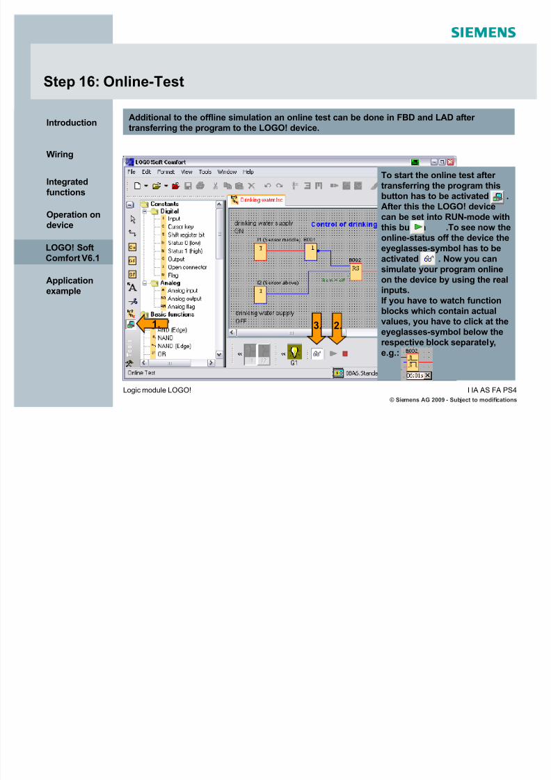
5/12/2018 LOGO! in Details - slidepdf.com
http://slidepdf.com/reader/full/logo-in-details 130/146
© Siemens AG 2009 - Subject to modifications
I IA AS F A PS4Logic module LOGO!
Introduction
Wiring
Integrated
functions
Operation ondevice
LOGO! SoftComfort V6.1
Applicationexample
Step 16: Online-Test
Additional to the offline simulation an online test can be done in FBD and LAD after transferring the program to the LOGO! device.
1. 2.3.
To start the online test after transferring the program thisbutton has to be activated .
After this the LOGO! devicecan be set into RUN-mode withthis button .To see now theonline-status off the device theeyeglasses-symbol has to be
activated . Now you cansimulate your program onlineon the device by using the realinputs.
If you have to watch functionblocks which contain actualvalues, you have to click at theeyeglasses-symbol below therespective block separately,e.g.:
LOGO! SoftComfort V6.1

5/12/2018 LOGO! in Details - slidepdf.com
http://slidepdf.com/reader/full/logo-in-details 131/146
© Siemens AG 2009 - Subject to modifications
I IA AS F A PS4Logic module LOGO!
Introduction
Wiring
Integrated
functions
Operation ondevice
LOGO! SoftComfort V6.1
Applicationexample
Step 17: Setting the clock
With help of the software you can set the system clock of LOGO! as well. Of course, youcan also set the time directly on the device.
LOGO! and PC have to be connected viathe PC cable to transfer the set time toLOGO!, then you have to click on the
button Wr i te.
LOGO! SoftComfort V6.1

5/12/2018 LOGO! in Details - slidepdf.com
http://slidepdf.com/reader/full/logo-in-details 132/146
© Siemens AG 2009 - Subject to modifications
I IA AS F A PS4Logic module LOGO!
Introduction
Wiring
Integrated
functions
Operation ondevice
LOGO! SoftComfort V6.1
Applicationexample
Step 17: Setting the clock
With LOGO! you have the possibility to configure an automatic summer / winter clockchange. You can do this on the software or directly on the device.
LOGO! and PC have to be connected via the PCcable to transfer the set summer / winter clock
change to LOGO!. Depending on the chosenregion this clock change is used.
LOGO! SoftComfort V6.1

5/12/2018 LOGO! in Details - slidepdf.com
http://slidepdf.com/reader/full/logo-in-details 133/146
© Siemens AG 2009 - Subject to modifications
I IA AS F A PS4Logic module LOGO!
Introduction
Wiring
Integrated
functions
Operation ondevice
LOGO! SoftComfort V6.1
Applicationexample
With Set AI3 and AI4 posi t i on you can choose toenable the optional AI3 and AI4 on the LOGO!0BA6 devices that have an option of four analoginputs. Your choices are as follows:
2 AIs: Only AI1 and AI2 corresponding to inputterminals I7 and I8 are available for use in your circuit program.
4 AIs: AI1 and AI2 corresponding to input
terminals I7 and I8 are available for use in your circuit program. Additionally, AI3 and AI4corresponding to input terminals I1 and I2 areavailable for use.
Set via software:
Double-click at in your circuit program
or go to Fil e -> Pro pert i es -> Parameter
or at LOGO! basic module:
Set up > BM AI NUM
Setting the position of analog inputs AI3 and AI4
LOGO! SoftComfort V6.1

5/12/2018 LOGO! in Details - slidepdf.com
http://slidepdf.com/reader/full/logo-in-details 134/146
© Siemens AG 2009 - Subject to modifications
I IA AS F A PS4Logic module LOGO!
Introduction
Wiring
Integrated
functions
Operation ondevice
LOGO! SoftComfort V6.1
Applicationexample
Modem wizard
LOGO! SoftComfort V6.1
LOGO! Soft Comfort V6.1 provides a wizard to configure 11-bit analog modems that usestandard AT commands and to connect them via an analog telephone line.
You can use the modems to transfer circuit programs between LOGO! Soft Comfort V6.1and LOGO! devices.

5/12/2018 LOGO! in Details - slidepdf.com
http://slidepdf.com/reader/full/logo-in-details 135/146
© Siemens AG 2009 - Subject to modifications
I IA AS F A PS4Logic module LOGO!
Introduction
Wiring
Integrated
functions
Operation ondevice
LOGO! SoftComfort V6.1
Applicationexample
Modem wizard
First you have to make a few settings for you COM-Port:Select in Windows Start -> Sett ings -> Control Panel -> S y stem -> H ar d ware -> Devi ce
Manager . Then select Ports -> open the pro pert i es window of your COM-Port.
LOGO! SoftComfort V6.1
The port settings must be as follows:
Bits per second: 9600
Data bits: 8
Parity: Even
Stop bits: 1
Flow control: None

5/12/2018 LOGO! in Details - slidepdf.com
http://slidepdf.com/reader/full/logo-in-details 136/146
© Siemens AG 2009 - Subject to modifications
I IA AS F A PS4Logic module LOGO!
Introduction
Wiring
Integrated
functions
Operation ondevice
LOGO! SoftComfort V6.1
Applicationexample
Modem wizard
LOGO! SoftComfort V6.1
1.
2.
Select the Tool s -> Connect Mod em menu command tostart the wizard. LOGO! Soft Comfort V6.1 displays adialog that guides you through the configuration process.

5/12/2018 LOGO! in Details - slidepdf.com
http://slidepdf.com/reader/full/logo-in-details 137/146
© Siemens AG 2009 - Subject to modifications
I IA AS F A PS4Logic module LOGO!
Introduction
Wiring
Integrated
functions
Operation ondevice
LOGO! SoftComfort V6.1
Applicationexample
Modem wizard
First the remote modem has to be configured. This configuration has to be made via adirect connection between PC and modem.
LOGO! SoftComfort V6.1
Every modem that you configure gets aname. In the wizard default AT-commandsare already entered which are used of most modems. You can type in other AT-commands if necessary for your modem.Disable d ef aul t in this case.
4.
5.
Now you can click at ³ConfigureRemote Modem´.

5/12/2018 LOGO! in Details - slidepdf.com
http://slidepdf.com/reader/full/logo-in-details 138/146
© Siemens AG 2009 - Subject to modifications
I IA AS F A PS4Logic module LOGO!
Introduction
Wiring
Integrated
functions
Operation ondevice
LOGO! SoftComfort V6.1
Applicationexample
Modem wizard
Next step is to configure the local modem. The procedure is similar to the configuration of the remote modem.
LOGO! SoftComfort V6.1
7.
8.The modem wizardprovides a list of telephone numbers.Here several numbersof remote stations canbe entered. Select the
number you want tocall and click Di al .

5/12/2018 LOGO! in Details - slidepdf.com
http://slidepdf.com/reader/full/logo-in-details 139/146
© Siemens AG 2009 - Subject to modifications
I IA AS F A PS4Logic module LOGO!
Introduction
Wiring
Integrated
functions
Operation ondevice
LOGO! SoftComfort V6.1
Applicationexample
Modem wizard
After dialing the remote modem, you are able to up-/download the user program, set LOGO!in run/stop and do online- test.
LOGO! SoftComfort V6.1

5/12/2018 LOGO! in Details - slidepdf.com
http://slidepdf.com/reader/full/logo-in-details 140/146
© Siemens AG 2009 - Subject to modifications
I IA AS F A PS4Logic module LOGO!
Introduction
Wiring
Integrated
functions
Operation ondevice
LOGO! SoftComfort V6.1
Applicationexample
Delete user program and password
To be able to reuse a LOGO! with program and password when password is lost, thepassword has to be entered incorrectly three times at program deletion. Then the programand the PW is automatically deleted. *)In LOGO! ..0BA6 it is possible to delete user program and password by LOGO! Soft ComfortV6.1 .This function is especially helpful for LOGO! pure versions, where it is not possible to
delete the program directly on the device via the keys. In generations prior ..0BA6, amemory cartridge was necessary to get the program deleted.Use Tool -> Transf er -> C l ear User Program and Passwor d .
LOGO! SoftComfort V6.1
*) since E-Stand 4 (ES4) only possible via software or memory card

5/12/2018 LOGO! in Details - slidepdf.com
http://slidepdf.com/reader/full/logo-in-details 141/146
© Siemens AG 2009 - Subject to modifications
I IA AS F A PS4Logic module LOGO!
Introduction
Wiring
Integrated
functions
Operation ondevice
LOGO! SoftComfort V6.1
Applicationexample
Power-on Screen for LOGO! TD
Use Tool s -> Transf er -> Set LO G O! TD Power-on Screen to configure a power-on screen for the LOGO! TD. This screen gets displayed during LOGO! TD powers up.
LOGO! SoftComfort V6.1

5/12/2018 LOGO! in Details - slidepdf.com
http://slidepdf.com/reader/full/logo-in-details 142/146
© Siemens AG 2009 - Subject to modifications
I IA AS F A PS4Logic module LOGO!
Introduction
Wiring
Integrated
functions
Operation ondevice
LOGO! SoftComfort V6.1
Applicationexample
Miscellaneous options
Other miscellaneous settings can be made via the menu item Tool s -> O pt i ons.
LOGO! SoftComfort V6.1

5/12/2018 LOGO! in Details - slidepdf.com
http://slidepdf.com/reader/full/logo-in-details 143/146
© Siemens AG 2009 - Subject to modifications
I IA AS F A PS4Logic module LOGO!
Introduction
Wiring
Integrated
functions
Operation ondevice
LOGO! SoftComfort V6.1
Applicationexample
Application example
Conveyor controller
Applicationexample

5/12/2018 LOGO! in Details - slidepdf.com
http://slidepdf.com/reader/full/logo-in-details 144/146
© Siemens AG 2009 - Subject to modifications
I IA AS F A PS4Logic module LOGO!
Introduction
Wiring
Integrated
functions
Operation ondevice
LOGO! SoftComfort V6.1
Applicationexample
Conveyor control
Function description:
A bottle filling conveyor shall be controlled.
Part 1
The conveyor control is switched on and off via (I1).
When the conveyor control is switched on, the conveyor motor (Q1) runs. If thelight barrier (I3) is interrupted, the motor shall be switched off.
Part 2When the sensor (I2) detects a bottle, the motor is to be switched off for 3 sec.(filling action). After that the motor runs again.
I1(ON/OFF)
I3(light barrier)
I2 (filling)
Q1
Applicationexample

5/12/2018 LOGO! in Details - slidepdf.com
http://slidepdf.com/reader/full/logo-in-details 145/146
© Siemens AG 2009 - Subject to modifications
I IA AS F A PS4Logic module LOGO!
Introduction
Wiring
Integrated
functions
Operation ondevice
LOGO! SoftComfort V6.1
Applicationexample
Solution: Conveyor control part 1
Function description:
Part 1
The conveyor control is switched on and off via (I1).When the conveyor control is switched on, the conveyor motor (Q1) runs. If the light barrier (I3) is interrupted, the motor shall be switched off.
Applicationexample
I1(ON/OFF)
I3(light barrier)
I2 (filling)
Q1
Invertierter Eingang
S l i C l 2

5/12/2018 LOGO! in Details - slidepdf.com
http://slidepdf.com/reader/full/logo-in-details 146/146
Introduction
Wiring
Integrated
functions
Operation ondevice
LOGO! SoftComfort V6.1
Applicationexample
Solution: Conveyor control part 2
Function description:
Part 2
When the sensor (I2) detects a bottle, the motor is to be switched off for 3 sec.(filling action). After that the motor runs again.
Edge triggered
Applicationexample
I1(ON/OFF)
I3(light barrier)
I2 (filling)
Q1