login to rtn huawei
DESCRIPTION
telcomTRANSCRIPT

Login To RTN Huawei

PC IP Configuration Guide (Windows XP SP2)

Page 3
Configure PC IP
1)Righit click the icon
2)Move cursor to here, then select
Desktop: Windows XP SP2
• Configure PC IP address

Page 4
Configure PC IP
1)Righit click the icon
2)Move cursor to here, then select
• Configure PC IP address

Page 5
Configure PC IP
Move cursor to here, then select
• Configure PC IP address

Page 6
Configure PC IP
Configure IP address:129.9.XX.XX. The address can’t same with Equipment’s IP.
• Configure PC IP address

NE Login and Board Configure(RTN 600 V1R2)

Page 8
NE Login PC connect with NE (RTN 600)
• RTN 620
• RTN 605
ETH
Laptop
ETH
Laptop
Page 9
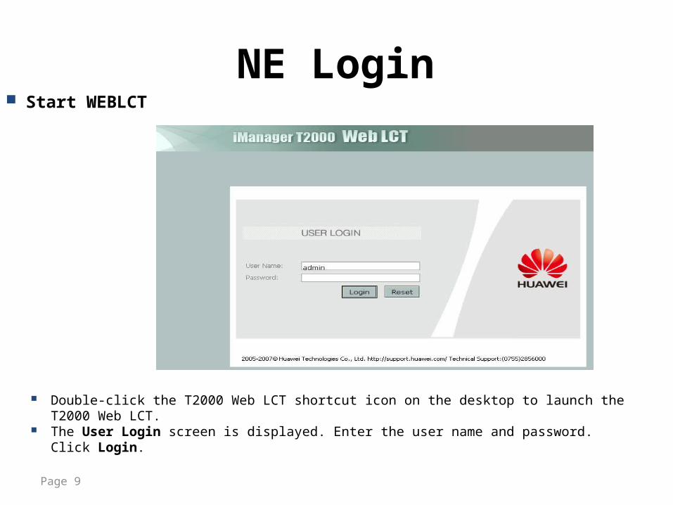
NE Login Start WEBLCT
Double-click the T2000 Web LCT shortcut icon on the desktop to launch the T2000 Web LCT. The User Login screen is displayed. Enter the user name and password. Click Login.

Page 10
NE Login
③
②
①
④
Searched NE list.
Search NE

Page 11
NE Login Add NE
All available NE will be added on the screen.
Communication Status should be normal.
Page 12
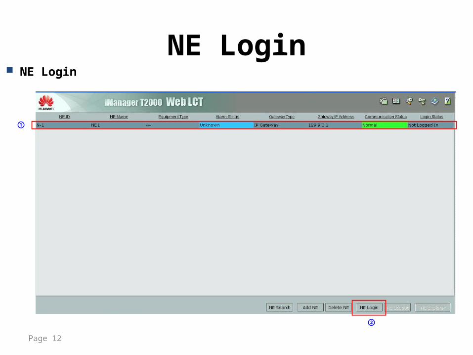
NE Login NE Login
②
①

Page 13
NE LoginUser name: lctPassword: password.
③
④
Login NE

Page 14
Configure NE
②
①
Start to Configure NE

Page 15
Configure NE Change NE ID
Can’t use the same NE ID in a network.
③
②
① Configure NE name.

Page 16
Configure NE Re-login NE
①
② ③

Page 17
Configure NE
③
②
①
④
Configure board
The color of created board is green,
Method 1: Added by batch.

Page 18
Configure NE
③
②
①
Configure board
Method 1: Added one by one.
• Right click on the board then pressed “ADD”.
• PXC Card should be installed FIRST.

1+1 HSB-FD-SD Commissioning

Page 20
Basic Knowledge• 1+1 Configuration
For RTN 620, the paired slots (slot5 and slot7) consist a 1+1 protection group; the paired slots (slot6 and slot8) consist another 1+1 protection group.
Slot 5 and slot 6 is main slot respectively.
For 1+1 HSB and SD application, It is only necessary to configure main IF board parameters.
For 1+1 FD application, It is necessary to configure main parameters and standby parameters respectively.

Page 21
Basic Knowledge• Trigger Conditions of the automatic HSB switching
Switching Conditions Description
The hardware of the IF board is faulty.
At the same priority.
The hardware of the ODU is faulty.
POWER_FAIL
VOLT_LOS( IF Board)RADIO_TSL_HIGH
RADIO_TSL_LOW
RADIO_RSL_HIGH
IF_INPWR_ABN
CONFIG_NOSUPPORT
R_LOC
R_LOF
R_LOS
MW_LOF
The IF connection cable is faulty.

Page 22
Basic Knowledge• Trigger Conditions of the automatic HSM switching
Switching Conditions Description
R_LOC
HighR_LOF
R_LOS
MW_LOF
MW_FECUNCOR Medium
B1_SD (IDU 620 PDH)
LowB2_SD (IDU 620 SDH )
MW_BER_SD( IDU 605 2B/2F)

Page 23
Basic Knowledge
Coupler Type Description Application Receive Power
Asymmetrical Hybrid Coupler(6dB)
with one main channel and one standby channel.
Main ODU port insertion loss, dB max:1.8 (38G: 2.0);Standby ODU port insertion loss, dB max: 7.2 (38G:7.4)
Symmetrical Hybrid Coupler (3dB)
with equal attenuation in both channels
ODU port insertion loss, db max:3.8 (38G:4.0).
• Hybrid Coupler with Waveguide Interface

Page 24
Basic Knowledge• Trigger Conditions and Antenna Aligning
Alarms R_LOF,R_LOS,MW_LOF are the microwave link alarm.
While aligning antennas, the microwave link is not stable, will create these alarms.
In order to finish antennas aligning quickly, for 1+1 application, we suggest turn off the standby IF ODU-PWR switch at first, after antenna aligning finishing, turn on the standby IF ODU-PWR.

Page 25
Basic Knowledge
Item HSB FD SD Notes
Quantity of ODU 2 2 2 HSB/SD: main ODU type is same as standby.
Quantity of Antenna 1 1/2 2 _
Quantity of Hybrid Coupler 1 1/0 0 _
Quantity of Frequency Channel 1 2 1 HSB/SD: Only configure main IF parameters.FD: Configure main and standby IF parameters respectively.
HSB Support √ √ √ —
HSM Support × √ √ —
• 1+1 HSB/FD/SD Compare

CONTENT
• Basic Knowledge• 1+1 HSB• 1+1 FD• 1+1 SD

Page 27
1+1 HSB Commissioning• 1+1 HSB Commissioning Steps
Link 1+1 Configure ParametersConfigure
Turn off Standby IF ODU-PWR Switch Align Antenna
Turn on Standby IF ODU-PWR
Switch
1+1 Switch State and Test

Page 28
1+1 HSB Commissioning• Link 1+1 Configure
To Next Page
①
②
③
④

Page 29
1+1 HSB Commissioning• Link 1+1 Configure

Page 30
1+1 HSB Commissioning• IP Parameters Configure
①
②
③
④
⑤
For 1+1 HSB, only configure main IF board parameters.

Page 31
1+1 HSB Commissioning• Query 1+1 HSB Switch State
①
②
④
③
Switch State

Page 32
1+1 HSB Commissioning• 1+1 Switch Control
①
②
④
③
Right Click

CONTENT
• Basic Knowledge• 1+1 HSB• 1+1 FD• 1+1 SD

Page 34
1+1 FD Commissioning
Link 1+1 Configure ParametersConfigure
Turn off Standby IF ODU-PWR Switch Align Antenna
Turn on Standby IF ODU-PWR
Switch
1+1 Switch State and Test
• 1+1 FD Commissioning Steps

Page 35
1+1 FD Commissioning• Link 1+1 Configure

Page 36
1+1 FD Commissioning• IF Parameters Configure
①
②
③
④⑤
⑥ ⑦
⑧

Page 37
1+1 FD Commissioning• IF Parameters Configure
①
②
④⑤
⑥ ⑦
⑧
③

CONTENT
• Basic Knowledge• 1+1 HSB• 1+1 FD• 1+1 SD

Page 39
1+1 SD Commissioning• 1+1 SD Commissioning Steps
Link 1+1 Configure IF ParametersConfigure
Turn off Standby IF ODU-PWR Switch
Align main Antenna
Turn on Standby IF ODU-PWR
Switch
Align Standby Antenna

Page 40
1+1 SD Commissioning• 1+1 Link Configure

Page 41
1+1 SD Commissioning• Parameters Configure
①
②
③
④
⑤
For 1+1 SD, only configure main IF board parameters.

Page 42
1+1 SD Commissioning Turn off two side standby ODU's power, turn on two main ODU's power, firstly, align two
main antennas.
√: ODU Power on.X: ODU Power off.

Page 43
1+1 SD Commissioning Turn on local site standby ODU's power, keep opposite site main antenna fixed, align local
standby antenna towards opposite main one.
√: ODU Power on.X: ODU Power off.

Page 44
1+1 SD Commissioning Turn on opposite standby ODU's power, keep local main antenna fixed, align opposite
standby antenna towards local main one.
√: ODU Power on.X: ODU Power off.