locating the house on 9 the building...
TRANSCRIPT

Locating the House on the Building Site
Discuss the PhotoSurveying Many surveying and layout tasks require two people to work together as a team. What features of this instrument allow one person to complete the task?
Writing Activity: Step-by-Step DirectionsMany locating tasks have step-by-step directions. Preview the step-
by-step activities in this chapter. Then, create step-by-step directions for a simple task, such as hammering a nail into a board.
Chapter ObjectivesAfter completing this chapter, you will be able to:
• Create a simple building layout, working from an existing reference line.
• Identify the basic types of surveying instruments and list their limitations.
• Use a builder’s level to lay out a right angle.
• Describe how to set up batter boards.
• Explain how to measure a difference in elevation between two points using a level or transit.
• Calculate the volume of soil excavated for a house foundation.
Section 9.1Basic Site Layout
Section 9.2Establishing Lines & Grades
9
234 Chapter 9 Locating the House on the Building Site Ian Francis/Alamy

Content Vocabulary Defi nition
theodolite a transit that reads horizontal and vertical angles electronically
Content Vocabulary
Academic VocabularyYou will fi nd these words in your reading and on your tests. Use the academic vocabulary glossary to look up their defi nitions if necessary.
■ methods ■ locate ■ visible
Graphic OrganizerAs you read, use a chart like the one shown to organize content vocabulary words and their defi nitions, adding rows as needed.
9
Academic Standards
Mathematics
Measurement: Apply appropriate techniques, tools, and formulas to determine measurements (NCTM)Geometry: Analyze characteristics and properties of two- and three-dimensional geometric shapes and develop mathematical arguments about geometric relationships (NCTM)
English Language Arts
Use information resources to gather information and create and communicate knowledge (NCTE 8)
Science
Science and Technology: Abilities of technological design (NSES)Science in Personal and Social Perspectives: Science and technology in local, national, and global challenges (NSES)
Industry StandardsMeasuring DistanceLevelingSite Layout
NCTE National Council of Teachers of EnglishNCTM National Council of Teachers of Mathematics
NSES National Science Education Standards
●● plot plan●● site layout●● theodolite ●● bench mark
●● station mark●● batter board●● differential leveling●● bearing capacity
●● porosity●● overdig
Go to glencoe.com for this book’s OLC for a downloadable version of this graphic organizer.
Before You Read PreviewBefore a house can be built, its location on the plot of land must be accurately established. Choose a content vocabulary or academic vocabulary word that is new to you. When you fi nd it in the text, write down the defi nition.
Chapter 9 Reading Guide 235

E
G H Positionof house
X OXO
A B
C D
F
Property lines
Basic Techniques What is a reference line?
The plot plan is the part of the house plans that shows the location of the building on the lot, along with related land elevations (see Section 2.3). The location of the building must then be marked out on the land itself, in a process referred to as site layout. This may be done by a surveyor or by a builder familiar with basic surveying methods.
The purpose of site layout is to position the house correctly on the lot. The position of the house on the site must meet local building and zoning codes. Other factors also apply, such as the placement of utilities. The position may have been chosen to take advantage of views, to increase privacy, or to avoid a site feature such as a ledge (area of rock below grade) or a stream.
The position of the house may also have been chosen to maxi-mize solar heat gain for increased energy effi ciency, as shown in Figure 9-1.
Two basic methods can accurately deter-mine the location of a proposed building on a property:• Measuring from an existing reference line.• Using a surveying instrument such as a
level or a transit.
Measuring From a Reference LineA building may be planned so that it is
parallel to an existing line, such as a street or marked property line. Such a line can then be used as a guide, or reference line. This makes it possible to stake out the site without using a surveying instrument. When working in this way, it is best to make a drawing of the prop-erty fi rst. Such a drawing is shown in Figure 9-2. Rectangle ABCD represents the property lines, and boundary AB is the reference line.
Using Surveying InstrumentsWhen a building cannot be laid out by
working from reference lines, the builder or surveyor can use one of several kinds of surveying instruments. These instruments work with either optical or laser technol-ogy, though some are based on GPS (global positioning system) technology.
Site Layout9.1
Figure 9-1 Solar ElectricityUsing the Sun This house uses photovoltaic panels to generate electricity from the sun. For these to work effi ciently, the house must be placed properly on the lot.
Figure 9-2 Staking a BuildingSimple Layout Staking out a rectangular building without the use of a surveying instrument.
236 Chapter 9 Locating the House on the Building Site Walter Geiersperger/Corbis

Users of optical instruments rely on line-of-site observations to determine position. The user must look through the instrument’s telescope to spot a target or leveling rod held by an assistant. A leveling rod is a slender, straight rod marked with graduations in feet and fractions of a foot. The rod is held in a vertical position during use.
Laser instruments do not have a telescope. Instead, a highly focused beam of light is aimed at the target. The user does not need to look through the instrument, so an addi-tional person is not required. One person can set up the laser and then move to another portion of the site and determine level by holding an electronic detector against a leveling rod. When the detector senses the reference plane projected by the laser, it signals the user with a light or sound. The disadvantage of a laser instrument is that its light can be diffi cult to see in bright daylight.
GPS instruments are the newest develop-ment in surveying systems. GPS stands for global positioning system. GPS consists of two parts, handheld instruments and 24 satellites evenly distributed around Earth’s orbit. Each of these satellites transmits a unique signal, and when a GPS instrument receives several signals, it is able to locate its position on Earth’s surface with great accuracy. These systems are much more expensive than opti-cal or laser surveying instruments, but they are being used increasingly for construction site layouts.
Types of InstrumentsThe two basic types of surveying instru-
ments commonly used in residential con-struction are levels and transits. Both sit atop a tripod.
Levels The telescope of a level is fi xed in a horizontal plane. It can be used only for measuring horizontal angles because it cannot be tilted up or down. It can only be turned from side to side. This is suffi cient for most building layouts. There are three types of levels.
A builder’s level, shown in Figure 9-3, is sometimes called a dumpy level. It is the least expensive surveying instrument. It must be set up carefully to ensure accurate results. A good quality model is usually accurate to within ±1⁄4" at a distance of 75'.
An automatic level, as shown in Figure 9-4, automatically adjusts for variations in setup. It takes less time and effort to set up than a builder’s level. It is also more accurate, usually to ±1⁄4" at 100'. Some are accurate to ±1⁄16" at 200'.
A laser level, as shown in Figure 9-5 on page 238, does not have a telescope, but is set up on a tripod like other levels. It proj-ects its intense beam of light along a hori-zontal plane. The light shows up as a small red dot at great distances. Some models continually rotate atop the tripod. They project what appears to be a solid, level line around the job site. Other laser levels can be
Figure 9-4 Automatic LevelImproved Accuracy An automatic level is more accurate than a builder’s level.
Figure 9-3 Builder’s LevelLeast Expensive A builder’s level is suitable for small or simple layout tasks.
Figure 9-4 Automatic LevelImproved Accuracy An automatic level is more accurate than a builder’s level.
Section 9.1 Basic Site Layout 237Arnold & Brown; David R. Frazier Photolibrary, Inc.

Telescope
Levelingscrews
rotated as needed using a remote control. Some laser levels use an audible sound to signal a certain level point.Transits The transit, shown in Figure 9-6, is sometimes called a transit level. Unlike the telescope of a level, the telescope of the transit can be moved up and down as well as from side to side. A transit can measure horizontal angles and vertical angles as well. It can also be used to determine if a post or wall is plumb.
A transit is classifi ed by the smallest incre-ment that can be read on its vernier scale. (A vernier scale slides along a longer scale.) The graduations on a vernier scale are in minutes or seconds. A transit may be referred to as a fi ve-minute transit, a one-minute transit, or a twenty-second transit. Measurements made in seconds are more accurate. A theodolite, as shown in Figure 9-7, is a transit that reads horizontal and vertical angles electronically. It needs no vernier scale. It displays the measurements on an LCD (liquid-crystal display) screen. It is used when extremely accurate measurements are required. A device called an electronic fi eld book can be attached to a theodolite to store information. A theodolite is easy to set up.
Recall What are the two tools used to determine the location of a building on the site?
Basic Layout with a Level or Transit Most of the basic layouts described on the
following pages can be made with a level.
Figure 9-7 TheodoliteTracking Information This surveyor is entering information into a theodolite, or electronic transit. What information might be entered?
Figure 9-6 TransitPlumb and Level A transit can be used for site layout but can also determine if parts of the building are plumb.
Figure 9-5 Laser LevelRemote Control A laser level makes it possible for one person to determine elevation points.
238 Chapter 9 Locating the House on the Building Site David R. Frazier Photolibrary, Inc.; Spencer Grant

Bubble
Levelingscrews
All of them can be made using a transit. The same concepts apply to the use of other surveying instruments, although layout methods will differ.Locating a Bench Mark To lay out a building using a transit or a level, you must fi rst have a basic starting point. This starting point, from which measurements can be made, is usually called the bench mark, or point of reference (POR). A bench mark may be a mark on the foundation of a nearby building. More often it is a stone or concrete marker placed on the ground at a certain location. The location of the bench mark may appear on the architect’s drawings. If so, the plans will usually be oriented to that point.Setting Up a Transit or Level Set up the transit or level in a position outside the expected fl ow of activities on a job site. This will prevent it from being accidentally disturbed.
The point over which the level is directly centered is called the station mark. The layout is sighted from this point. The station mark may be a bench mark or a corner of the lot, but it should be where the lot can be conveniently sighted. (If the bench mark and the station mark are not the same, be sure you can sight the bench mark easily.)
A plumb bob is suspended from a hook beneath the head of the instrument. Use this plumb bob to center the level or transit directly over the station mark. Adjust the tripod so that it rests fi rmly on the ground, with the telescope at eye level.
Once a level or transit has been properly set up, be careful not to move or jar the tripod. If this occurs, the instrument must be readjusted. Some or all of the sightings may have to be redone.
Go to glencoe.com for this book’s OLC for additional step-by-step procedures, applications, and certifi cation practice.
Leveling a Transit Head After you have chosen a position for the transit or level, level the instrument’s head:
Step 1 Loosen the horizontal clamp screw and turn the telescope until the bubble is in line with one set of opposing leveling screws. Grip the screws, one in each hand, using a thumb and forefi nger. Loosen one screw as you tighten the other to center the bubble. Keep the screws snug on the foot plate but do not overtighten them. Continue to adjust the screws until the bubble is centered. See Figure 9-8.
Step 2 Rotate the telescope 90° so that it is over the second set of leveling screws and repeat the process described in Step 1.
Step 3 Return the telescope to the fi rst position. Check the bubble to be sure it is centered, and readjust if necessary. Recheck the second position.
Step 4 Continue to check the bubble in both positions until it is within one graduation on either side of center in the bubble tube.
Figure 9-8 Leveling ControlsLevel with Care The level of the head of the instrument can be adjusted by using the leveling screws and checking the bubble.
Section 9.1 Basic Site Layout 239David R. Frazier Photolibrary, Inc.
CA D B E
A
D
C90
B
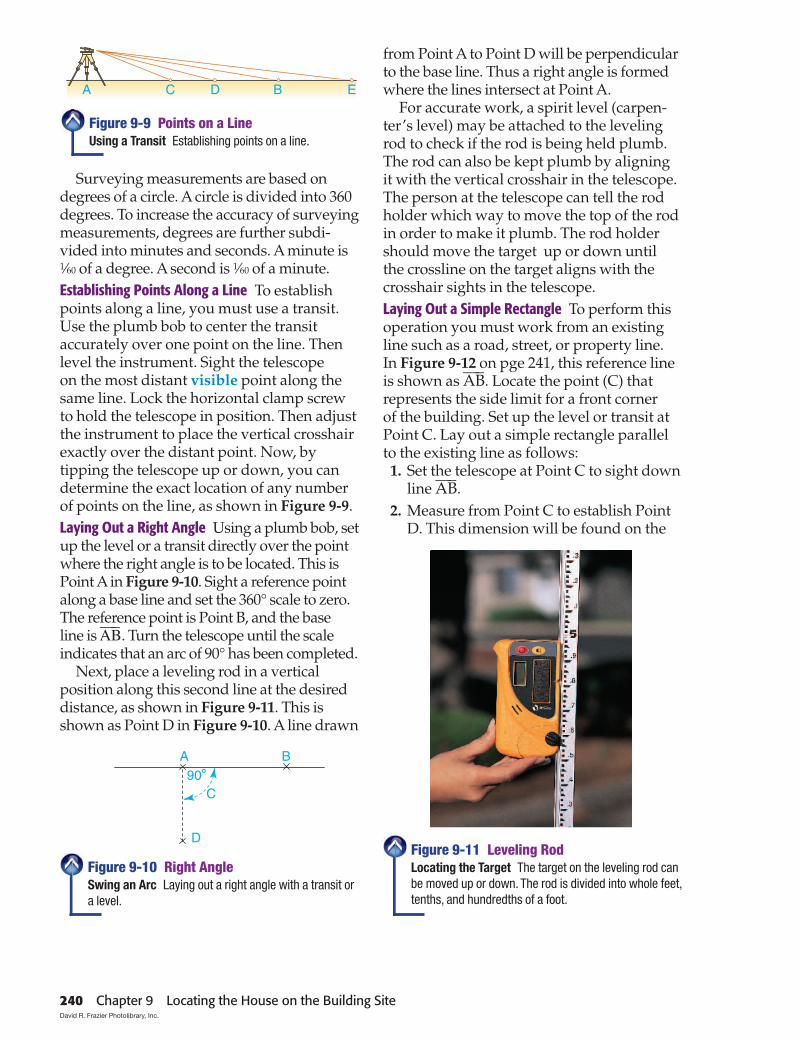
Surveying measurements are based on degrees of a circle. A circle is divided into 360 degrees. To increase the accuracy of surveying measurements, degrees are further subdi-vided into minutes and seconds. A minute is 1⁄60 of a degree. A second is 1⁄60 of a minute.Establishing Points Along a Line To establish points along a line, you must use a transit. Use the plumb bob to center the transit accurately over one point on the line. Then level the instrument. Sight the telescope on the most distant visible point along the same line. Lock the horizontal clamp screw to hold the telescope in position. Then adjust the instrument to place the vertical crosshair exactly over the distant point. Now, by tipping the telescope up or down, you can determine the exact location of any number of points on the line, as shown in Figure 9-9.Laying Out a Right Angle Using a plumb bob, set up the level or a transit directly over the point where the right angle is to be located. This is Point A in Figure 9-10. Sight a reference point along a base line and set the 360° scale to zero. The reference point is Point B, and the base line is
_A
_B. Turn the telescope until the scale
indicates that an arc of 90° has been completed. Next, place a leveling rod in a vertical
position along this second line at the desired distance, as shown in Figure 9-11. This is shown as Point D in Figure 9-10. A line drawn
from Point A to Point D will be perpendicular to the base line. Thus a right angle is formed where the lines intersect at Point A.
For accurate work, a spirit level (carpen-ter’s level) may be attached to the leveling rod to check if the rod is being held plumb. The rod can also be kept plumb by aligning it with the vertical crosshair in the telescope. The person at the telescope can tell the rod holder which way to move the top of the rod in order to make it plumb. The rod holder should move the target up or down until the crossline on the target aligns with the crosshair sights in the telescope.Laying Out a Simple Rectangle To perform this operation you must work from an existing line such as a road, street, or property line. In Figure 9-12 on pge 241, this reference line is shown as
_A
_B. Locate the point (C) that
represents the side limit for a front corner of the building. Set up the level or transit at Point C. Lay out a simple rectangle parallel to the existing line as follows: 1. Set the telescope at Point C to sight down
line _A
_B.
2. Measure from Point C to establish Point D. This dimension will be found on the
Figure 9-10 Right AngleSwing an Arc Laying out a right angle with a transit or a level.
Figure 9-11 Leveling RodLocating the Target The target on the leveling rod can be moved up or down. The rod is divided into whole feet, tenths, and hundredths of a foot.
Figure 9-9 Points on a LineUsing a Transit Establishing points on a line.
240 Chapter 9 Locating the House on the Building Site David R. Frazier Photolibrary, Inc.

C D
F
BA
G H
E
Building 40'A B
51'-211 /16"
Tapemeasure
Tapemeasure
Established line
Back cornerof building
32'
Building
Q
N
P
A BC D
E F
G H
J
K O
IM
L
building plans. It represents the width of the building.
3. Turn the telescope 90° and establish Points E and G by measurement.
4. Move the level or transit to Point D and sight through the telescope to Point C.
5. Turn the telescope 90° and establish Points F and H by measurement.
6. Points E and F represent the front corners of the building. To check your accuracy, measure lines
_E
_F and
_G
_H. They should
be the same length. Check the layout for square by measuring diagonally from Point E to point H, and from Point F to Point G. If these two measurements are identical, the layout is square.
Another method of laying out a rectan-gular project is to fi gure the diagonal of the rectangle, as shown in Figure 9-13. After one side of the project is established (
_A
_B), usu-
ally the front setback line, the rectangle can be laid out accurately by using two long tape measures. The side and end measurements are input as rise and run into a construction
calculator, and the diagonal of the rectangle is fi gured automatically. Using one tape measure, measure the desired distance from one end of line AB. Then, with a second tape measure, measure the diagonal. The lines will intersect precisely at one of the corners. Do this from both ends of the established line and a perfect rectangle is established. The example in Figure 9-13 shows a house that is 40' long and 32' deep. It has a diagonal of 51'-211⁄16".Laying Out an Irregularly Shaped Building When the building is not regular in shape, it is usually best to start by laying out a large rectangle that will take in all or most of the building. This is shown in Figure 9-14 as QHOP. After the large rectangle is established,
Figure 9-13 Rectangle Layout: Method #2Using Two Tapes Measure from each end of the established line AB. The back corner will be where the diagonal measurement (51'-211⁄16") and the end measurement (32') intersect.
Figure 9-14 An Irregular ShapeMultiple Shapes Laying out an irregularly shaped building made of a series of squares and rectangles.
Figure 9-12 Rectangle Layout: Method #1Basic Layout Laying out a square or rectangular building with a level or transit.
Section 9.1 Basic Site Layout 241

E
G H Positionof house
X OXO
A B
C D
F
Property lines
the remaining portion of the layout will consist of small rectangles. Each small rectangle can be laid out and proved sepa-rately. These rectangles are shown as NMLP, ABCQ, DGFE, and JIOK.
Even if the outline of a building is not a rectangle, the process for establishing each point is basically the same. More points must be located, and the fi nal check is more likely to reveal a small error.
Go to glencoe.com for this book’s OLC for additional step-by-step procedures, applications, and certifi cation practice.
Staking Out the Site To stake out the site in the drawing, proceed as follows:
the lot. Points G and H represent the rear corners of the building.
Step 4 The boundary lines of the lot may not be at right angles to each other. If this is the case, you will need to fi rst establish the corner of the building that will be closest to a boundary line. Next, make certain that the minimum front and side yard requirements are established from this point. Then lay out the building by using the methods described on page 240, “Laying Out a Right Angle” and “Laying Out a Simple Rectangle.” Establish a line to indicate the rear of the building. This is shown by GH in Figure 9-2.
Step 5 If the building is complicated, divide it into smaller rectangles. Establish more lines such as_O
_O to indicate the front of each rectangle. You
can get the necessary information from the plans. Then carry out the same steps to establish the rest of each rectangle. The result will be a group of adjoining rectangles that will show the total outline of the building.
Step 1 Check the plot plan to fi nd the setback dis-tance. The setback distance is the minimum space allowed by local codes between a house and the property lines. Codes also specify setback distances between the house and utility lines, streams, and ponds. Along boundaries
_A_C and
_B_D, measure this
distance back from front line _A_B. In the drawing,
the setback is shown by segments _A_O and
_B_O.
Step 2 Stretch a line tightly between the points marked O. The front corners of the building will be located on line
_O
_O. There are two ways to locate
them. You can obtain the measurement from the plot plan to see how far the corners should be from the side boundaries. Then, along line
_O
_O,
measure the indicated distances in from _A_C and _
B_D. Xs represent the front corners of the building
in Figure 9-2. If the building is to be centered between the side boundaries, you need not refer to the plot plan. Instead, subtract the length of the building from the length of
_O
_O. Then measure half
this distance in from each end of _O
_O. Measure the
distance between the two points marked X and check this distance with the plans. The distance
_X_X
represents the length of the building. It must be accurately measured and match the length on the plans.
Step 3 Check the plans to determine the depth of the building (how far back it will extend from the front corners). Mark off the depth by extending lines back from the two points marked X. If the boundary lines of the lot form a 90° angle at the corners, these lines should be parallel to
_A_C and _
B_D. Note that E is the same as
_O
_X, and F is the same
as_X_O. Thus, E and F show the distance between the
sides of the building and the side boundary lines of
242 Chapter 9 Locating the House on the Building Site
40'
20'10'
10' 10'
30'
Establishing Lines & Grades 9.2
Lines & GradesWhat is an excavation?
After its location and alignment have been determined, a rectangle showing the outer dimensions of a structure is staked out. If the building is to form a simple rectangle, the staked-out area will follow the foundation line exactly.
GradeThe grade refers to the level of the
ground where it will meet the foundation of the completed building. The grade is found on the building plans. Grade must be established accurately because it is used for making important measurements. From the grade, you can fi nd the depth of
After You Read: Self-Check 1. What is a plot plan? 2. Name one advantage of surveying instruments based on laser technology. 3. What is the difference between a level and a transit? 4. What is the purpose of the hook under a level or transit?
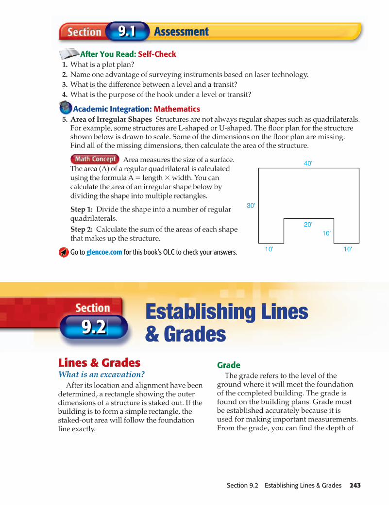
Academic Integration: Mathematics 5. Area of Irregular Shapes Structures are not always regular shapes such as quadrilaterals.
For example, some structures are L-shaped or U-shaped. The fl oor plan for the structure shown below is drawn to scale. Some of the dimensions on the fl oor plan are missing. Find all of the missing dimensions, then calculate the area of the structure.
Area measures the size of a surface. The area (A) of a regular quadrilateral is calculated using the formula A � length � width. You can calculate the area of an irregular shape below by dividing the shape into multiple rectangles.
Step 1: Divide the shape into a number of regular quadrilaterals.Step 2: Calculate the sum of the areas of each shape that makes up the structure.
Go to glencoe.com for this book’s OLC to check your answers.
9.1
Section 9.2 Establishing Lines & Grades 243

Outside line offoundation wall
Diagonals are equalif building is square
the excavation. An excavation is a cut, cav-ity, trench, or depression made by removing earth.
Sometimes the bench mark is used as a reference point for establishing the grade. At other times, the grade may be located in rela-tion to the level of an existing street or curb. The grade is indicated on a stake driven into the ground outside the excavation area.
You can also use the grade to establish other points, such as the height of a foundation or the elevation of the fi rst fl oor.
Batter BoardsAfter the grade and the corners of the
house have been established, building lines must be laid out as aids in keeping the work level and true. A batter board is a board
Go to glencoe.com for this book’s OLC for additional step-by-step procedures, applications, and certifi cation practice.
Setting Up Batter Boards Refer to Figure 9-15. After the corners of the building have been located, set up the batter boards as follows:
Step 1 Drive three 2�4 stakes at each corner of the building, at least 4' beyond the foundation lines.
Step 2 Nail 1�6 or 1�8 boards to the stakes horizontally. The top of each board must be level. All boards must be level with each other. Use a level or transit to locate the height of the boards.
Step 3 Stretch string across the tops of boards at opposite corners and align it exactly over the nails in the corner stakes. A plumb bob is handy for setting the lines.
Step 4 Make a shallow saw kerf where the string overlaps the boards. This will keep the string from sliding. It will also make it easy to reposition the string if it must be temporarily removed to let equipment or machinery pass. Make similar cuts in all eight batter boards.
Step 5 Tie the string to the boards, using the saw kerfs to position it (see Figure 9-16 on page 245). This establishes the lines of the house.
Step 6 Check the diagonals again to make sure the corners are square. (The area for an L-shaped building can be divided into rectangles and the diagonal measurement of each rectangle can be checked.)
Figure 9-15 Using Batter BoardsBuilding Outline Using batter boards to establish the outline of the foundation wall. The top edge of a batter board represents the height of the foundation wall.
244 Chapter 9 Locating the House on the Building Site

Stake
Batter board
Saw kerf
Plumbbob
Nail
Stake
Outside line offoundation wall
Taut line
15'-0"
9'-0"12'-0"
4'-0" Min.
fastened horizontally to stakes placed to the outside of where the corners of the building will be located. These boards and the string tied between them locate and mark the outline of the building as shown in Figure 9-15. The height of the boards may be the height of the foundation wall. Before setting up batter boards, locate the corners of the building precisely by one of the methods already discussed. Drive nails into the tops of the stakes that indicate the outside edge of the foundation walls.
Setting up batter boards is explained in the Step-by-Step Application.
To be certain that the corners are square, use the following procedure: 1. Measure the diagonals of the completed
layout to see if they are the same length, as shown in Figure 9-15.
2. The corners can also be squared by using the 3-4-5 method shown in Figure 9-16. This is done by measuring a distance along one side in 3' increments, such as 6, 9, or 12.
3. Measure along the adjoining side in the same number of 4' increments (8, 12, or 16). The diagonal drawn between the end points will then measure in an equal number of 5' units (10, 15, or 20) when the unit is square. Thus, a 9' distance on one side and a 12' distance on the other should result in a 15' diagonal measurement if the corner is a true 90°.
Land ElevationsCheck the architect’s plan to see where
elevations are to be determined. Set up a level or transit. Be certain that the locations can be seen through the telescope. Place a leveling rod upright on any location to be checked. Then sight through the telescope at the leveling rod. Take a reading of where the horizontal crosshair in the telescope crosses the rod. Then move the rod to the second location to be established. Raise or lower the rod until the reading is the same as for the fi rst point. The bottom of the rod is then at the same elevation as the original point.
Figure 9-16 Batter Board DetailSquaring a Corner You can check that the corners of a layout are square by using the 3-4-5 system.
Section 9.2 Establishing Lines & Grades 245

A
5'
B
7'
A
C DB
5'
7' 1'2'51/2'
41/2'
Measuring a Difference in Elevation To learn the difference in elevation between two points, such as A and B in Figure 9-17, set up a transit or level at an intermediate point. With the measuring rod held at point A, note the mark where the horizontal crosshair in the telescope crosses the rod. Then with the rod held at point B, sight the rod and note the point where the horizontal crosshair crosses the rod. In our example, the difference between the reading at A (5' 0") and the read-ing at B (7' 0") is the difference in elevation between A and B. Thus the ground at point B is 2' lower than the ground at point A. This technique can be used to position foundation footings and other points below grade.
Sometimes it is not possible to sight two points from a single point between them. A high mound can cause this diffi culty. To solve this problem, one or more additional intermediate points, such as C and D shown in Figure 9-18, must be used for setting up
the instrument. The process of determining differences in elevation between points that are remote from each other is called differential leveling.
Recall What points can be established using the grade?
Foundation Wall HeightThe foundation wall footings must rest
on fi rm soil below the frost line. Footings are continuous concrete pads that support a foundation wall. The depth of the frost line varies according to the local climate and is given in local building codes. This deter-mines how deep the excavation must be. To determine this depth, it is common practice to use the highest point on the perimeter of the excavation as the reference point, as
Figure 9-17 Elevation Difference #1Points Visible Obtaining the difference in elevation between two points that are visible from an intermediate point.
Figure 9-18 Elevation Difference #2Points Not Visible Obtaining the difference in elevation between two points not visible from a single intermediate point.
246 Chapter 9 Locating the House on the Building Site

Reference orhigh point
Foundation walloutline
Foundationwall
Minimum 8" clearance
Finish gradeDrain awayfrom house
Original grade
Fill
shown in Figure 9-19. This is true for both graded and ungraded sites.
Good drainage is ensured if suffi cient foundation height is allowed for the sloping of the fi nish grade, as shown in Figure 9-20. Finish grade is the level of the ground when grading is completed. Foundation walls at least 7'-4" high are necessary for full base-ments, and 8' walls are common.
The top of the foundation wall must be at or above a minimum height set by code. This distance is often at least 8" above the fi nished grade, but this may vary with local code. This allows the siding and framing members to be protected from soil moisture and places them well above the grass line. In termite-infested areas, this makes it possible to observe signs of any termite activity between the soil and the wood. Protective measures can then be taken before the wood is damaged.
Crawl spaces should have enough height to permit inspections for ter-mites and to allow plastic soil covers to be installed. Soil covers reduce the effect of ground moisture on framing members. Ordinarily, there should be at least 18" between the undersides of the joists and the highest point of ground enclosed by the foundation walls.
If the ground beneath the structure is excavated or is otherwise lower
than the outside fi nished grade, measures must be taken to assure good drainage. The fi nished grade should always slope away from the house, as shown in Figure 9-20. Below-surface drainage systems might also be required.
The ExcavationAny variation from standard
construction practices increases the cost of the foundation and footings. This might infl uence the design of the house. Before excavating for a new home, subsoil conditions should be determined
by test borings or by obtaining soil samples in some other way. This has several pur-poses. It helps the excavators to determine whether any special precautions will be necessary. Unusually soft or hard soil conditions may call for special excava-tion techniques or equipment. It is also important to know the bearing capacity of the soil. Bearing capacity is a measure of how well the soil can support the weight of a house. Another purpose of soil testing
Figure 9-20 Proper DrainageFinished Grade Added fi ll brings the fi nish grade above the original grade and ensures drainage away from the house.
Figure 9-19 Determining Excavation DepthHighest Point To establish the depth of the excavation, use the highest point around the excavation as the reference point.
Section 9.2 Establishing Lines & Grades 247

is to determine its porosity. Porosity is the measurement of the ability of water to fl ow through the soil. If the soil does not drain well, additional material may have to be excavated and replaced with better soil.
Test borings will also identify problems that could signifi cantly affect the cost of the house. A rock ledge may require costly removal. A high water table may require design changes from a full basement to a crawl space or concrete slab construction. If there has been a previous excavation on the site, the soil may have been disturbed and may not have suffi cient bearing strength for footings.
Several types of earth-moving equipment, such as a power shovel or backhoe, can be used for basement excavations. Topsoil is often stockpiled by a bulldozer, a front-end loader, or a grader for future use, as in Figure 9-21. Power trenchers are often used in excavating slab footings or shallow foun-dation walls.
It is best to excavate only to the top of the footings or the bottom of the basement fl oor. The soil must be stable enough to prevent cave-ins, and some soil becomes soft upon
exposure to air or water. Thus, unless form boards are to be used, it is advisable not to make the fi nal excavation for footings until it is nearly time to pour the concrete.
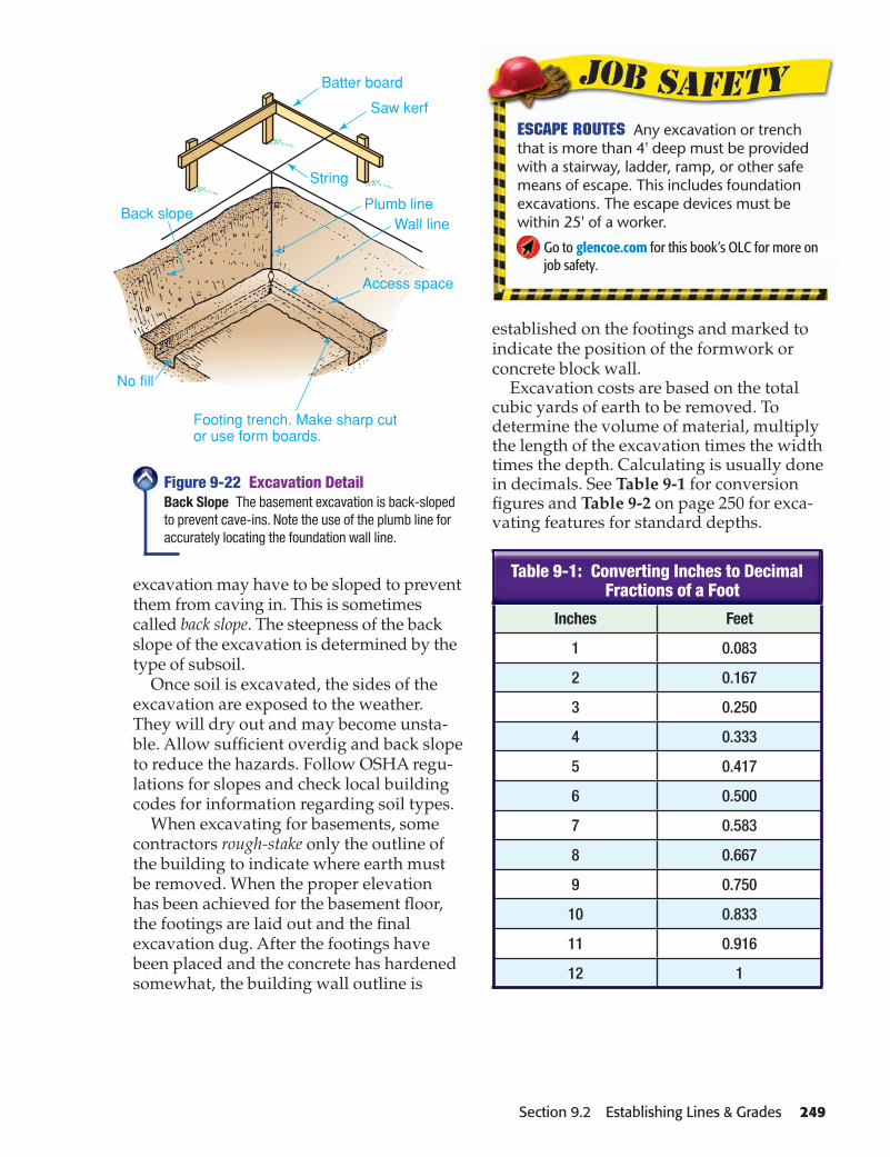
The excavation must be wide enough to provide space to work, as shown in Figure 9-22. For example, there must be enough room to install and remove concrete forms, to lay up block, to waterproof the exterior surfaces of the walls, and to install founda-tion drainage. Overdig is the term used to describe the additional excavation needed to provide clearance for work. The sides of the
Call Before You Dig Utility lines that are accidentally severed can pose a serious risk to workers. Before excavating, contact the local utility companies for information about the location of sewer, telephone, fuel, electric, water, or cable lines that may cross the area. Locations should then be clearly marked.
Go to glencoe.com for this book’s OLC for more on job safety.
Figure 9-21 Grading the SiteStockpiling Topsoil A grader being used to strip the topsoil from a building site in preparation for excavating the basement.
248 Chapter 9 Locating the House on the Building Site David Young-Wolff
Batter board
Saw kerf
Plumb lineWall line
Footing trench. Make sharp cutor use form boards.
No fill
Back slope
Access space
String
Inches Feet
1 0.083
2 0.167
3 0.250
4 0.333
5 0.417
6 0.500
7 0.583
8 0.667
9 0.750
10 0.833
11 0.916
12 1
established on the footings and marked to indicate the position of the formwork or concrete block wall.
Excavation costs are based on the total cubic yards of earth to be removed. To determine the volume of material, multiply the length of the excavation times the width times the depth. Calculating is usually done in decimals. See Table 9-1 for conversion fi gures and Table 9-2 on page 250 for exca-vating features for standard depths.
Figure 9-22 Excavation DetailBack Slope The basement excavation is back-sloped to prevent cave-ins. Note the use of the plumb line for accurately locating the foundation wall line.
excavation may have to be sloped to prevent them from caving in. This is sometimes called back slope. The steepness of the back slope of the excavation is determined by the type of subsoil.
Once soil is excavated, the sides of the excavation are exposed to the weather. They will dry out and may become unsta-ble. Allow suffi cient overdig and back slope to reduce the hazards. Follow OSHA regu-lations for slopes and check local building codes for information regarding soil types.
When excavating for basements, some contractors rough-stake only the outline of the building to indicate where earth must be removed. When the proper elevation has been achieved for the basement fl oor, the footings are laid out and the fi nal excavation dug. After the footings have been placed and the concrete has hardened somewhat, the building wall outline is
Table 9-1: Converting Inches to Decimal Fractions of a Foot
Escape Routes Any excavation or trench that is more than 4' deep must be provided with a stairway, ladder, ramp, or other safe means of escape. This includes foundation excavations. The escape devices must be within 25' of a worker.
Go to glencoe.com for this book’s OLC for more on job safety.
Section 9.2 Establishing Lines & Grades 249
Depth per Square Foot
Cubic Yards Removed
Depth per Square Foot
Cubic Yards Removed
2" 0.006 4'-6" 0.167
4" 0.012 5'-0" 0.185
6" 0.018 5'-6" 0.204
8" 0.025 6'-0" 0.222
10" 0.031 6'-6" 0.241
1'-0" 0.037 7'-0" 0.259
1'-6" 0.056 7'-6" 0.278
2'-0" 0.074 8'-0" 0.298
2'-6" 0.093 8'-6" 0.314
3'-0" 0.111 9'-0" 0.332
3'-6" 0.130 9'-6" 0.350
4' 0.148 10'-0" 0.369Note: To fi nd the factor, fi rst locate the excavation depth. The factor is in the column to the right.
Excavation Volume
This estimating and planning exercise will prepare you for national competitive events with organizations such as
SkillsUSA and the Home Builder’s Institute.
Excavation CostsMultiply the length of the excavation
times the width times the depth to deter-mine the volume of the material to be removed.
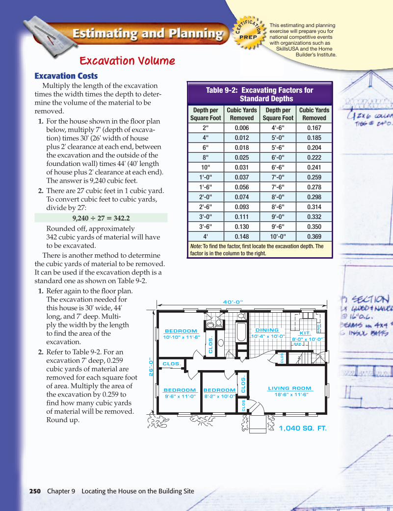
1. For the house shown in the fl oor plan below, multiply 7' (depth of excava-tion) times 30' (26' width of house plus 2' clearance at each end, between the excavation and the outside of the foundation wall) times 44' (40' length of house plus 2' clearance at each end). The answer is 9,240 cubic feet.
2. There are 27 cubic feet in 1 cubic yard. To convert cubic feet to cubic yards, divide by 27:
9,240 � 27 � 342.2 Rounded off, approximately
342 cubic yards of material will have to be excavated.
There is another method to determine the cubic yards of material to be removed. It can be used if the excavation depth is a standard one as shown on Table 9-2.
1. Refer again to the fl oor plan. The excavation needed for this house is 30' wide, 44' long, and 7' deep. Multi-ply the width by the length to fi nd the area of the excavation.
2. Refer to Table 9-2. For an excavation 7' deep, 0.259 cubic yards of material are removed for each square foot of area. Multiply the area of the excavation by 0.259 to fi nd how many cubic yards of material will be removed. Round up.
Table 9-2: Excavating Factors for Standard Depths
250 Chapter 9 Locating the House on the Building Site

Depth in
Inches
Trench Width in Inches
12 18 24 30 36 42 48
6 1.9 2.8 3.7 4.6 5.6 6.6 7.4
12 3.7 5.6 7.4 9.3 11.1 13.0 14.8
18 5.6 8.3 11.1 13.9 16.7 19.4 22.3
24 7.4 11.1 14.8 18.5 22.2 26.0 29.6
30 9.3 13.8 18.5 23.2 27.8 32.4 37.0
36 11.1 16.6 22.2 27.8 33.3 38.9 44.5
42 13.0 19.4 25.9 32.4 38.9 45.4 52.0
48 14.8 22.2 29.6 37.0 44.5 52.0 59.2
54 16.7 25.0 33.3 41.6 50.0 58.4 66.7
60 18.6 27.8 37.0 46.3 55.5 64.9 74.1
After You Read: Self-Check 1. What are three possible reference points for establishing a grade? 2. What is a batter board and what is its purpose?3. Briefl y describe the process of identifying the difference in elevation between two points.
4. What is overdig?
Academic Integration: Science5. The Water Table During excavation, soil samples must be obtained to identify any poten-
tial problems that could signifi cantly affect the cost of construction. For example, a high water table may require design changes from a full basement to a crawl space or concrete slab construction. Find out more about the science of the water table. Write a few sentences about your fi ndings. Be sure to defi ne water table, then explain the difference between the saturated zone and the unsaturated zone.
Go to glencoe.com for this book’s OLC to check your answers.
9.2
Trenches The amount of material that will be removed from trenches, such as those trenches that might be dug for utilities, can be calculated by using Table 9-3. For example, if a trench is to be 42" deep and 18" wide, the table shows that 19.4 cubic yards of material will be removed for every 100 lineal feet. Such a trench might be dug for a house with a 30' setback. To determine how much material would be removed, multiply 19.4 by 0.30 (because 30' is about 0.30 of 100'). The answer is that 5.82 cubic yards of material would be removed.
Table 9-3: Cubic Yard Content of Trenches per 100 Lineal Feet
Volume How many cubic yards of material will be removed for a trench that is 24" deep, 24" wide, and 100 lineal feet long?Starting Hint Consult Table 9-3.
Measurement
Section 9.2 Establishing Lines & Grades 251

9
Review Content Vocabulary and Academic Vocabulary 1. Use each of these content vocabulary and academic vocabulary words in a sentence or diagram.
Content Vocabulary• plot plan (p. 236)• site layout (p. 236)• theodolite (p. 228)• bench mark (p. 239)• station mark (p. 239)
• batter board (p. 244)• differential leveling (p. 246)• bearing capacity (p. 247)• porosity (p. 248)• overdig (p. 248)
Academic Vocabulary• methods (p. 236)• locate (p. 237)• visible (p. 240)
Like a ProTechnical Terms 2. Work with a classmate to defi ne the follow-
ing terms used in the chapter: reference line (p. 236), leveling rod (p. 237), builder’s level (p. 237), dumpy level (p. 237), automatic level (p. 237), laser level (p. 237), vernier scale (p. 238), 3-4-5 method (p. 245), fi nish grade (p. 247), back slope (p. 249), rough-stake (p. 249).
Review Key Concepts 3. Describe how to work from an existing
reference line to establish a simple building layout.
4. Describe the different types of surveying instruments.
5. Demonstrate how to use a builder’s level to lay out a right angle.
6. Demonstrate how to set up batter boards.
7. Explain how to use a transit or level to measure a difference in elevation between two points.
8. Explain how to determine the depth of an excavation for a house foundation.
Critical Thinking 9. Infer How could you best keep the cost of
foundations and footings for a building at a minimum?
Review and Assessment
9.1
Chapter SummaryA house can be positioned or located on a piece of property either by measuring from an established reference line or by using an instrument such as a level or a transit. Most layouts begin at a bench mark. Surveying instruments include levels and transits. The point at which they are set up is called the station mark.
String stretched between batter boards is used to establish the outline of a house. Once this has been done, the excavation can proceed. The excavation must be wide enough to provide space to work. Soil taken from an excavation is measured in cubic yards.
9.2
Section
Section
252 Chapter 9 Review and Assessment

Academic and Workplace Applications
10. Finding Volume A rectangular excavation 5' deep is needed to build a building that is to be 26' by 32'. How many cubic yards of material should be removed if a 2' clearance is needed outside the foundation walls?
The formula for fi nding the volume of a rectangular prism is V � lwh. To determine the actual dimen-sions of the excavation, draw a picture and label the length and width to account for the building and the clearance all around.
Step 1: Draw a picture of the dimensions of the building. Then add the clearance.
Step 2: Multiply the length by the width. Then multiply the result by the depth of the excavation.
Step 3: Use cubic units to express the volume of the material. Convert cubic feet to cubic yards.
11. Measurement Accuracy A surveyor makes a measurement of 60½' using a laser mea-sure. It is accurate to within ±¼". What is the range within which the actual length could fall?
Starting Hint All measurements fall within a range of accuracy depending on the size of the smallest mark on the measuring device used and the quality of the device. Determine the lower end of the range by subtracting the accuracy factor.
12. Career Skills: Problem Solving You are a member of a surveying crew that has been hired to survey a building site this Saturday. On Friday evening, the other two members of your crew call to inform you
that they will not be able to work on Satur-day. The job needs to be completed before Monday. You were planning on working with your crew members and have all of the optical instruments ready to use. Now you will have to determine how you will complete the surveying job alone. Describe what changes you can make in order to complete the job yourself in a one-page summary. Identify the equipment you will need and explain why this equipment will be suitable for the situation.
Multiple ChoiceDirections Choose the phrase that best completes the following statements.
13. The top edge of a batter board represents the ______.
a. depth of the foundation wallb. outside edge of the foundation wallc. height of the foundation walld. width of the foundation wall
14. A measure of how well the soil can support the weight of a house is called ______.
a. a bench markb. the bearing capacityc. an overdigd. the station mark
15. The purpose of a site layout is to ______.
a. position a house correctly on the lotb. determine the depth of an excavationc. locate a bench markd. maximize solar heat gain
Skipping a question when you do not know the answer can waste valuable time. A better strategy is to mark the answer you believe to be correct and come back to the question after you fi nish the test.
* These questions will help you practice for nationalcertifi cation assessment.
Chapter 9 Review and Assessment 253