localization and navigation of an assistive humanoid …martinet/publis/2012/asrhe12enric.pdf ·...
TRANSCRIPT

Localization and Navigation of an AssistiveHumanoid Robot in a Smart Environment
Enric CerveraRobotic Intelligence Lab
Jaume-I UniversityCastello-Spain
Amine Abou MoughlbayInstitut de Recherche en Communications
et Cybernetique de Nantes (IRCCyN)Ecole Centrale de Nantes - France
Philippe MartinetIRCCyN - Ecole Centrale de NantesInstitut Pascal - Clermont Ferrand
Abstract—Assistive humanoids that manipulate objects in ev-eryday environments are potentially useful to improve the livesof the elderly or disabled. To retrieve or deliver objects at home,precise localization is needed. But localization of humanoid robotsis a challenging issue, due to rough odometry estimation, noisyonboard sensing, and the swaying motion caused by walking.To overcome these limitations, we advocate for the use ofexternal sensors for localization and navigation in a smart homeenvironment. As opposed to a stand-alone self contained robot,our humanoid benefits from the information coming from othersensing devices in the environment. In order to achieve robustlocalization while walking, and retrieve an object from the floor,we use RGBD camera information from an external Kinectsensor. Monte Carlo localization estimates the 6D torso poseestimation of the humanoid, which is then used for closed-loopnavigation control. Experiments with a NAO humanoid point outthat, by cooperating with the environmental sensors, the overallprecision of robot navigation is dramatically improved.
I. INTRODUCTION
Object retrieval is remarked as a high priority task forassistive robots by people with physical disabilities. Humanoidrobots could potentially help people with motor impairmentsto retrieve dropped objects [1], [2]. But robust and preciserobot localization is a prerequisite for such task, and humanoidlocalization remains a challenging issue due to inaccurate footstep odometry and noisy onboard sensor observations duringwalking [3].
Since our humanoid is targeted to human-friendly indoorenvironments, a smart home endowed with networked sensorswould provide additional useful information to monitor bothhumans and robots. In smart environments, components areworking together by exchanging information via the localnetwork. The main idea behind the smart home concept isto use networked robots to integrate different services withinthe home as a means to control and monitor the entire livingspace [4]. Such services are not realized by a single full-equipped robot but by a combination of different elements suchas environmental sensors, cameras and human communicatingand cooperating through the network.
The Kinect is a powerful low-cost sensor which providescolor and range images, suitable for human motion detectionand tracking. Dingli et al. [5] have created an Ambient-Assisted Living application which monitors a person’s posi-tion, labels objects around a room and raises alerts in case
of falls. Stone and Skubic [6] have investigated this sensorfor in-home fall risk assessment. Ni et al. [7] use color-depthfusion schemes for feature representation in human actionrecognition.
In this paper, we present a localization and navigationmethod for a humanoid robot in an indoor smart environment.The Kinect sensor is used to monitor and track the 6D poseof the robot. Localization and navigation towards a detectedobject can then be achieved precisely. The rest of the paper isorganized as follows: related work on humanoid localizationis discussed in Section II; Section III presents the architectureof the system; localization and control of the humanoid isdescribed in Section IV; experimental results are presented inSection V; finally, Section VI draws some conclusions andoutlines future work extensions.
II. RELATED WORK
Accurate localization, which is considered to be mainlysolved for wheeled robots, is still a challenging problemfor humanoid robots [3]. When dealing with biped robots,many problems arise such as foot slippage, stability problemsduring walking, and limited payload capabilities, preventingprecise localization in their environment. In addition,humanoids usually cannot be assumed to move on a planeto which their sensors are parallel due to their walking motion.
In the last few years, Monte Carlo methods have beencommonly used to perform localization on mobile robots[8], as well as other methods including grid-based Markovlocalization and Kalman filtering [9]. Furthermore, manystudies have been made to solve the humanoid localizationproblem by tracking their pose in the two-dimensional space.Ido et al. [10] applied a vision-based approach and comparethe current image to previously recorded reference imagesin order to estimate the location of the robot. Owald et al.[11] and Bennewitz et al. [12] compared visual features toa previously learned 2D feature map during pose tracking.Pretto et al. [13] tracked visual features over time forestimating the robot’s odometry. Cupec et al. [14] detectedobjects with given shapes and colors in the local environmentof the humanoid and determine its pose relative to these
2
objects.
In addition to that, many techniques using laser range datahave also been developed. Stachniss et al. [15] presented anapproach to learn accurate 2D grid maps of large environmentswith a humanoid equipped with a Hokuyo laser scanner. Sucha map was subsequently used by Faber et al. [16] for humanoidlocalization in 2D. Similarly, Tellez et al. [17] developed anavigation system for such a 2D environment representationusing two laser scanners located in the feet of the robot.
Since a 2D map is often not sufficient for humanoidmotion planning, several methods use 2.5D grid maps whichadditionally store a height value for each cell. Thompson et al.[18] track the 6D pose of a humanoid equipped with a laserscanner in such a representation. Hornung et al. [3] track ahumanoid’s 6D pose in a 3D world model, which may containmultiple levels connected by staircases.
In the cited methods, they used either embedded camerasand sensors on the robot or exteroceptive ones which aremounted on the robot’s head or body. All these sensorsare usually used to track the environment and subsequentlylocalize the robot.
In our method, the sensors are fixed and used to localizethe walking robot. The contribution of this paper is a robustlocalization system for humanoid robots navigating in indoorenvironments using Kinect cameras. The main goal is todevelop a robust system which is able to track and localizethe robot when walking, and control its motion preciselyenough, to be able to retrieve an object from the floor.
III. SYSTEM’S ARCHITECTURE
The system is composed of a small humanoid robot NAO,navigating in an indoor smart environment, where a 3D visionsystem, consisting of one or more low cost Kinect cameras,monitors and tracks both the user and robot activity, asdepicted in Fig. 1.
In our current implementation, the system is able to detectsmall objects lying on the floor plane, as well as to localize therobot. In the future, we will incorporate the skeletal trackingof the Kinect sensor, to be able to interface directly withhuman gestures. This section briefly describes the hardwarecomponents along with the system software framework.
A. Kinect sensor
The used vision system is the Kinect camera, which consistsof two optical sensors whose interaction allows a three-dimensional scene analysis. One of the sensors is an RGBcamera which has a video resolution of 30 fps. The imageresolution given by this camera is 640x480 pixels. The secondsensor has the aim of obtaining depth information correspond-ing to the objects found at the scene. The working principle ofthis sensor is based on the emission of an infrared signal whichis reflected by the objects and captured by a monochromeCMOS sensor. A matrix is then obtained which provides adepth image of the objects in the scene, called DEPTH. An
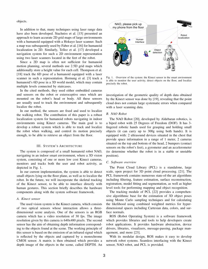
NAO, please pick upmy phone from the floor
Robotlocalization
Objectdetection
HumanInterface
Fig. 1. Overview of the system: the Kinect sensor in the smart environmentis able to monitor the user activity, detect objects on the floor, and localizeprecisely the robot.
investigation of the geometric quality of depth data obtainedby the Kinect sensor was done by [19], revealing that the pointcloud does not contain large systematic errors when comparedwith a laser scanning data.
B. NAO Robot
The NAO Robot [20], developed by Aldebaran robotics, isa biped robot with 25 Degrees of Freedom (DOF). It has 3-fingered robotic hands used for grasping and holding smallobjects (it can carry up to 300g using both hands). It isequipped with: 2 ultrasound devices situated in the chest thatprovide space information in a range of 1 meter, 2 camerassituated on the top and bottom of the head, 2 bumpers (contactsensors on the robot’s feet), a gyrometer and an accelerometer(to determine whether the robot is in a stable or unstableposition).
C. Software overview
The Point Cloud Library (PCL) is a standalone, largescale, open project for 3D point cloud processing. [21]. ThePCL framework contains numerous state-of-the art algorithmsincluding filtering, feature estimation, surface reconstruction,registration, model fitting and segmentation, as well as higherlevel tools for performing mapping and object recognition.
The tracking module of PCL [22] provides a comprehen-sive algorithmic base for the estimation of 3D object posesusing Monte Carlo sampling techniques and for calculatingthe likelihood using combined weighted metrics for hyper-dimensional spaces including Cartesian data, colors, and sur-face normals.
ROS (Robot Operating System) is a software frameworkwhich provides libraries and tools to help developers createrobot applications. It provides hardware abstraction, devicedrivers, libraries, visualizers, message-passing, package man-agement, and more [23].
With its modular design, ROS makes it easy to developnetwork robot systems. Seamless interfacing with the Kinectsensor, NAO robot, and PCL is provided.
3

Fig. 2. 3D tracking of the NAO robot with Kinect.
IV. LOCALIZATION AND NAVIGATION
A. Localization
This technique consists of tracking 3D objects (positionand orientation) in continuous point cloud data sequences. Itwas originally designed for robots to monitor the environmentand make decisions and adapt their motions according to thechanges in the world, but it is equally suitable for trackingthe robot while it walks around the environment (Fig. 2).Localization has been optimized to perform computationsin real-time, by employing multi CPU cores optimization,adaptive particle filtering (KLD sampling) and other moderntechniques [22].
In our application, we use a rigid model of the torso andhead parts of the robot, to track the system on real-time andfind the 3D pose of the robot model even when walking. Infuture works, an articulated model could be used to track thewhole body of the robot.
Using the PCL Cloud tracking technique we can find theactual pose of the robot and the desired one (the object)with respect to the Kinect. Thus the relative 3D pose can becalculated, and we can control the direction of walking in theplane: the position in X and Y directions and the orientationof the robot.
B. Navigation
The NAO robot is able to walk in velocity control mode.This enables the walk to be controlled reactively, as the mostrecent command overrides all previous commands. However,the walk uses a preview controller to guarantee stability. Thisuses a preview of time of 0.8s, so the walk will take thistime to react to new commands. At maximum frequency thisequates to about two steps [24].
The linear velocity of the robot (cVx,c Vy)
T is calculatedwith respect to the pose error between actual and desired poses(ex, ey, eθ)
T using a proportional gain λ. The aim is to movethe robot linearly to the target.
(cVxcVy
)= λ
(exey
)(1)
The angular velocity of the robot cω may be calculated intwo different manners: first, while the error is greater than
a given threshold emin, the robot will head towards the linejoining its current location and final destination; second, whenthe error is lower than such threshold, the robot will headtowards its final orientation.
cω =
{λ arctan(ey/ex) if
√e2x + e2y > emin
λeθ otherwise(2)
C. Veering correction
Closed-loop control is able to converge in the presenceof uncertainties in sensors and actuators. However, fasterconvergence is achieved if the system is properly calibrated. Ina similar way to human beings [25], biped robots suffer frominability to maintain a straight path when walking withoutvision: slight differences between each leg stride caused bybackslash, friction, or motor power will produce a veeringbehavior which can be estimated and corrected.
A simple veering correction procedure is now introduced:the robot is commanded in open-loop to walk straight awaywith a constant linear velocity. Its trajectory is recorded withthe Kinect sensor, and two fitting steps are performed:
1) Circle fitting: the best fitting circle is computed, asshown in Fig. 3a.
2) Line fitting: the robot is now commanded to walk with aconstant linear velocity, and a constant angular velocity,as computed from the previous fitting step. Fig. 3bdepicts the recorded trajectory, and the LMS line fitting.
The error is significantly reduced: without correction, fora 1m walked distance, the lateral error grows to 35cm, andthe orientation error is 30 (Fig. 3a). With angular correction(Fig. 3b), the orientation error is not noticeable, but a lateralerror persists, 25cm for a 1.5m walked distance. This error iscompensated an order of magnitude with a lateral velocityterm, resulting in only 3cm for the same walked distance(Fig. 3c).
As a result, for a given command motion, the actual velocitysent to the robot (rVx,
r Vy,r ω)T consists of the original
commanded values (cVx,c Vy,
c ω)T and compensation termsfor the lateral and angular velocity. The radius of the fittingcircle R and the slope of the fitting line m are used to computethe angular and lateral velocity compensation respectively:
rVxrVyrω
=
cVxcVy −mcVxcω −RcVx
(3)
Finally, the velocity is translated to NAO’s walk arguments(see [24] for details).
V. EXPERIMENTAL RESULTS
In the experiment, the robot is commanded to approach anobject lying on the floor as seen in Fig. 4. The initial distanceto the object is 1.5m and the orientation of the initial posewith respect to the final pose is 25 degrees.
Figs. 5, 6 and 7 depict respectively the commanded velocity,the pose error, and the planar trajectory of the robot.
4

(a) Circle fitting.
(b) Line fitting.
(c) Final trajectory.
Fig. 3. Veering correction: the robot is commanded open-loop to walk straightwith constant linear velocity. First, trajectory is recorded (a) and the best fittingcircle is computed. Second, a new trajectory is recorded (b) and a linear fittingis computed. The final trajectory with angular and lateral compensation isshown in (c).
Fig. 4. Experimental setup (external and Kinect views): as NAO robot entersthe room, it is commanded to move towards an object lying on the floor (theball on the left-bottom corner of the image). Floor lines are not consideredin the experiment.
As can be seen in Fig. 5, the robot initially walks towardsthe destination at full speed, then it progressively decreases itsvelocity as the error is diminished. The profile of the angularvelocity reflects the two stages defined in 2: from 0s to 19s,the robot turns towards the destination; after 19s the robot isnearer to the destination than the threshold (fixed to 30cm)and it turns to its final orientation.
This control strategy explains why the angular error utz inFig. 6 does not decrease initially, since this error is measuredwith respect to the final orientation of the robot.
The trajectory of the robot in the room is depicted inFig. 7. When using only odometry, the robot is not ableto attain the destination goal, but the final pose is 40 cmaway from the desired one. On the other hand, localization
rad/
sm
/s
time - [s]
Fig. 5. Robot velocity in NAO’s local frame: only planar and angular velocityis sent to the robot controller.
orie
ntat
ion
[rad
]po
sitio
n[m
]
time - [s]
Fig. 6. Pose error of the robot torso (position and orientation), as measuredby the Kinect sensor.
and closed-loop navigation allows the robot to attain the goalwithin a few centimeters precision. The final mean positionerror is (x, y, θ) = (0.012, 0.018, 0.07) and the standarddeviation is (σx, σy, σθ) = (0.002, 0.004, 0.05). In preliminaryexperiments, it has been possible to fetch an object from thefloor in such conditions.
VI. CONCLUSION
We have presented a localization and navigation methodfor a humanoid robot in a smart environment, where a Kinectsensor is used for monitoring and tracking the 3D pose of therobot.
This method is suitable for indoor environments, allowingnot only to detect the robot but also to track people who
5

start
goal
Odometry --Localization --
Fig. 7. Trajectories carried out in the experiments: while the odometrydiverges, localization is able to attain the goal.
interact with the robot.The accomplished precision of localization makes it possi-
ble to retrieve objects from the floor for assistance and servicerobotics. Further work will incorporate object manipulation tocomplete such task.
Further improvements are possible: obstacle detection withthe Kinect sensor would allow the robot to navigate robustly ina cluttered environment. The workspace of the robot would bescalable by using more Kinect sensors in a networked system.Finally, multimodal user interaction can be achieved by gestureand voice recognition.
ACKNOWLEDGMENT
This research was partly funded by Ministerio de Cien-cia e Innovacion (DPI2011-27846), Ministerio de Educacion(Programa ”Salvador de Madariaga”, referencia PR2011-015)Generalitat Valenciana (PROMETEO/2009/052) and FundacioCaixa Castello-Bancaixa (P1-1B2011-54). We wish to thankW. Khalil for making it possible for one of the authors to stayat the IRCCyN, Ecole Centrale de Nantes.
REFERENCES
[1] A. Jain and C. Kemp, “El-e: an assistive mobile manipulator thatautonomously fetches objects from flat surfaces,” Autonomous Robots,vol. 28, pp. 45–64, 2010.
[2] C.-H. King, T. L. Chen, Z. Fan, J. D. Glass, and C. C. Kemp, “Dusty:an assistive mobile manipulator that retrieves dropped objects for peo-ple with motor impairments,” Disability and Rehabilitation: AssistiveTechnology, vol. 7, no. 2, pp. 168–179, 2012.
[3] A. Hornung, K. M. Wurm, and M. Bennwitz, “Humanoid robot localiza-tion in complex indoor environments,” in 2010 IEEE/RSJ Int. Conf. onIntelligent Robots and Systems - IROS’10, oct. 2010, pp. 1690 – 1695.
[4] A. Sanfeliu, N. Hagita, and A. Saffiotti, “Network robot systems,”Robotics and Autonomous Systems, vol. 56, no. 10, pp. 793 – 797, 2008.
[5] A. Dingli, D. Attard, and R. Mamo, “Turning homes into low-costambient assisted living environments,” International Journal of AmbientComputing and Intelligence (IJACI), pp. 1–23, 2012.
[6] E. Stone and M. Skubic, “Evaluation of an inexpensive depth camerafor passive in-home fall risk assessment,” in Pervasive ComputingTechnologies for Healthcare (PervasiveHealth), 2011 5th InternationalConference on, may 2011, pp. 71 –77.
[7] B. Ni, G. Wang, and P. Moulin, “Rgbd-hudaact: A color-depth videodatabase for human daily activity recognition,” in Computer VisionWorkshops (ICCV Workshops), 2011 IEEE International Conference on,nov. 2011, pp. 1147 –1153.
[8] S. Thrun, D. Fox, W. Burgard, and F. Dellaert, “Robust montecarlo localization for mobile robots,” 2001. [Online]. Available:http://citeseerx.ist.psu.edu/viewdoc/summary?doi=10.1.1.18.8488
[9] J.-S. Gutmann, “Markov-kalman localization for mobile robots.” inICPR (2), 2002, pp. 601–604. [Online]. Available: http://dblp.uni-trier.de/db/conf/icpr/icpr2002-2.html#Gutmann02
[10] J. Ido, Y. Shimizu, Y. Matsumoto, and T. Ogasawara, “Indoornavigation for a humanoid robot using a view sequence.” I. J.Robotic Res., vol. 28, no. 2, pp. 315–325, 2009. [Online]. Available:http://dblp.uni-trier.de/db/journals/ijrr/ijrr28.html#IdoSMO09
[11] S. Owald, A. Hornung, and M. Bennewitz, “Learning reliable andefficient navigation with a humanoid.” in ICRA. IEEE, 2010,pp. 2375–2380. [Online]. Available: http://dblp.uni-trier.de/db/conf/icra/icra2010.html#OsswaldHB10
[12] M. Bennewitz, C. Stachniss, W. Burgard, and S. Behnke, “Metriclocalization with scale-invariant visual features using a singleperspective camera.” in EUROS, ser. Springer Tracts in AdvancedRobotics, H. I. Christensen, Ed., vol. 22. Springer, 2006, pp.195–209. [Online]. Available: http://dblp.uni-trier.de/db/conf/euros/euros2006.html#BennewitzSBB06
[13] A. Pretto, E. Menegatti, M. Bennewitz, W. Burgard, and E. Pagello, “Avisual odometry framework robust to motion blur.” in ICRA. IEEE,2009, pp. 2250–2257. [Online]. Available: http://dblp.uni-trier.de/db/conf/icra/icra2009.html#PrettoMBBP09
[14] R. Cupec, G. Schmidt, and O. Lorch, “Experiments in vision-guidedrobot walking in a structured scenario,” in Industrial Electronics, 2005.ISIE 2005. Proceedings of the IEEE International Symposium on, vol. 4,20-23, 2005, pp. 1581 – 1586.
[15] C. Stachniss, M. Bennewitz, G. Grisetti, S. Behnke, and W. Burgard,“How to learn accurate grid maps with a humanoid.” in ICRA. IEEE,2008, pp. 3194–3199. [Online]. Available: http://dblp.uni-trier.de/db/conf/icra/icra2008.html#StachnissBGBB08
[16] F. Faber, M. Bennewitz, A. Grg, C. Gonsior, D. Joho, M. Schreiber, andS. Behnke, “The humanoid museum tour guide robotinho,” in in IEEEInt. Symp. on Robot and Human Interactive Communication, 2009.
[17] R. A. Tllez, F. Ferro, D. Mora, D. Pinyol, and D. Faconti, “Autonomoushumanoid navigation using laser and odometry data.” in Humanoids.IEEE, 2008, pp. 500–506. [Online]. Available: http://dblp.uni-trier.de/db/conf/humanoids/humanoids2008.html#TellezFMPF08
[18] S. Thompson, S. Kagami, and K. Nishiwaki, “Localisation forautonomous humanoid navigation.” in Humanoids. IEEE, 2006, pp.13–19. [Online]. Available: http://dblp.uni-trier.de/db/conf/humanoids/humanoids2006.html#ThompsonKN06
[19] K. Khoshelham and S. O. Elberink, “Accuracy and resolution of kinectdepth data for indoor mapping applications,” Sensors, vol. 12, no. 2, pp.1437–1454, 2012.
[20] D. Gouaillier, V. Hugel, P. Blazevic, C. Kilner, J. Monceaux, P. Lafour-cade, and B. Marnier et al., “Mechatronic design of nao humanoid,” inIEEE Int. Conf. on Robotics and Automation, may 2009, pp. 769 –774.
[21] R. Rusu and S. Cousins, “3d is here: Point cloud library (pcl),” inRobotics and Automation (ICRA), 2011 IEEE International Conferenceon, may 2011, pp. 1–4.
[22] R. Ueda, “Tracking 3D objects with Point Cloud Library,” http://pointclouds.org/news/tracking-3d-objects-with-point-cloud-library.html, 2012, [Online; accessed 27-June-2012].
[23] M. Quigley, K. Conley, B. P. Gerkey, J. Faust, T. Foote, J. Leibs,R. Wheeler, and A. Y. Ng, “ROS: an open-source robot operatingsystem,” in ICRA Workshop on Open Source Software, 2009.
[24] A. Robotics, “Walk control – NAO Software 1.12.5 documenta-tion,” http://www.aldebaran-robotics.com/documentation/naoqi/motion/control-walk.html, 2012, [Online; accessed 27-June-2012].
[25] C. S. Kallie, P. R. Schrater, and G. E. Legge, “Variability in steppingdirection explains the veering behavior of blind walkers,” Journal ofExperimental Psychology: Human Perception and Performance, vol. 33,no. 1, 2007.
6