load balancing utilizing data redundancy in distributed
TRANSCRIPT

Eurographics Symposium on Parallel Graphics and Visualization (2011)T. Kuhlen, R. Pajarola, and K. Zhou (Editors)
Load Balancing Utilizing Data Redundancy in DistributedVolume Rendering
S. Frey and T. Ertl
Visualisierungsinstitut der Universität Stuttgart, Germany
0.3%
0
4.4%
1
6.4%
2
5.3%
3
9.8%
4
8.4%
5
6.5%
6
5.4%
7
12.4%
8
8.8%
9
6.9%
10
5.6%
11
3.9%
12
4.7%
13
5.1%
14
5.4%
15
(a) Number of ray samples per brick relative tothe total amount for a given view frustum
0 1 2 3
4 5 6 7
8 9 10 11
12 13 14 15
(b) Distribution of bricks todevices (different colors)
0
9
7
0
1
8
1
2
6
11
14
3
4
10
4
5
2
13
5
15
3
12
(c) Workload balanced over devices
Figure 1: The cost of volume bricks highly depends on parameters that are commonly adjusted interactively at runtime, mostnotably the camera position and orientation (Fig. 1(a)). In order to prevent significant delays caused by data transfers, wedistribute bricks to compute devices redundantly (Fig. 1(b)). This can be utilized by our scheduler to evenly distribute the loadacross all devices by shifting brick render tasks between devices without costly data transfers (Fig. 1(c)).
AbstractIn interactive volume rendering, the cost for rendering a certain block of the volume strongly varies with dy-namically changing parameters (most notably the camera position and orientation). In distributed environments– wherein each compute device renders one block – this potentially causes severe load-imbalance. Balancing theload usually induces costly data transfers causing critical rendering delays. In cases in which the sum of memoryof all devices substantially exceeds the size of the data set, transfers can be reduced by storing data redundantly.We propose to partition the volume into many equally sized bricks and redundantly save them on different computedevices with the goal of being able to achieve evenly balanced load without any data transfers. The bricks assignedto a device are widely scattered throughout the volume. This minimizes the dependency on the view parameters, asthe distribution of relatively cheap and expensive bricks stays roughly the same for most camera configurations.This again enables our fast and simple scheduler to evenly balance the load in almost any situation. In scenariosin which only very few bricks constitute the majority of the overall cost a brick can also be partitioned further andrendered by multiple devices.
Categories and Subject Descriptors (according to ACM CCS): I.3.1 [Computer Graphics]: Parallel processing—I.3.2 [Computer Graphics]: Distributed/network graphics—
1. Introduction
A great number of areas like medicine, material sciences,computational physics, and various other disciplines have to
deal with large volumetric data sets. For visually analyzingthis data, interactive visualization is demanded that does notcompromise quality. Parallel volume rendering is one of the
c© The Eurographics Association 2011.

S. Frey and T. Ertl / Load Balancing Utilizing Data Redundancy in Distributed Volume Rendering
most efficient techniques to achieve this goal by distributingthe rendering process over a cluster of machines. Particularlywhen dealing with large data sets, the volume data set is par-titioned and distributed to render nodes. Splitting the datain object space this way avoids the need for costly out-of-core techniques. However, a major issue arises from the factthat the rendering costs for the volume block that is assignedto a computation device changes significantly with param-eters like the camera position and orientation that are typi-cally adjusted interactively by the user. In order to balancethe load, the rendering of certain volume parts needs to bemoved from one device to another. Common dynamic load-balancing schemes require time consuming data transfers toachieve evenly balanced computation load. Even if this onlyinduces memory copies from main to device memory, it canstill cause significant rendering delays.
At the same time, the amount of nodes in a standard clus-ter as well as the available graphics card memory are steadilyincreasing. For a wide range of areas and applications, thetotal available amount of graphics memory would allow tostore the data set several times. However, common object-space distribution techniques usually save the whole data setin memory only once and maximally save data in boundaryregions redundantly. This largely wastes potential flexibilityfor load-balancing.
We propose to split the volume in many small volumeblocks called bricks and distribute them redundantly to com-pute devices. In each frame, for every brick a device is cho-sen for rendering that holds the respective brick in its mem-ory. A good distribution of bricks already allows for bal-anced execution times and due to the fact that typically mul-tiple bricks are rendered per device, there is no need for thebricks to be equally expensive.
In particular, we make the following contributions:
• Concept of redundantly distributing many small, equallysized bricks instead of allocating one brick per device.• Load-balancing technique exploiting the brick redun-
dancy to maximum effect.• Brick distribution algorithm to allow for good load-
balancing under all circumstances• Evaluation of the influence of camera position and orien-
tation on the brick rendering cost
The remainder of this paper is structured as follows. Sec. 2discusses related work in distributed volume rendering andscheduling. Sec. 3 gives an overview on our approach, whileSec. 4 and Sec. 5 discuss in detail its two phases, namely thea priori initialization and the per frame load-balancing. Weshow the effectiveness of our approach in Sec. 6.
2. Related Work
Distributed Volume Rendering
Distributed volume rendering has been investigated for
a long period of time and a magnitude of publications canbe found on this issue. Most of the existing systems fit ei-ther into the sort-first or sort-last category according to Mol-nar et al.’s classification [MCEF94]. Our approach is in thesort-last category, i.e. the data is split between the nodes,and each node renders its own portion. Compositing thentakes depth information into account to form a final im-age from each node’s rendering. Sort-last volume renderingtechniques are able to handle very large datasets as demon-strated by Wylie et al. [WPLM01] by statically distributingthese datasets among the nodes. The predominant hierar-chical compositing schemes that are used in sort-last archi-tectures aiming at rendering large data sets are the DirectSend approach by Neumann [Neu93] and the Binary-Swapalgorithm [MPHK93]. Palmer et al. [PTT97] discussed howto efficiently exploit all levels of the deep memory hierar-chy of a cluster system. Using the clusters that compute thesimulation also for volume rendering has also been investi-gated [PYRM08]. While the first techniques for parallel vol-ume rendering employed slice-based rendering [MHE01],more recent systems use GPU-based raycasting [KW03]with a single rendering pass [SSKE05]. A simple back-to-front raycaster in the CUDA SDK [NVI08] demonstrates theimplementation with a modern GPGPU language.
There has been a lot of work in recent years on datastructures that can be used to address dynamic load balanc-ing issues in distributed volume rendering systems. For in-stance, Wang et al. [WGS04] proposed a hierarchical space-filling curve for that purpose. Lee et al. [LSH05] employa hybrid/BSP tree subdivision. Müller et al. [MSE06] andMarchesin et al. [MMD06] amongst others employ a kd-treein order to dynamically reorganise the data distribution in acluster. Marchisin et al. [MMD06] also showed that whenzooming on parts of the data sets, load imbalance becomesa challenging issue. In order to achieve good load balanc-ing they dynamically distribute the data (i.e. they resize thevolume bricks) among the rendering nodes according to theload of the previous frame.
Similar to our approach, Peterka et al. [PRY∗08] generatemore volume bricks than there are devices. However, theyassign every brick to only device in initialization using around-robin scheme and no dynamic balancing takes placeduring rendering.
Frank and Kaufman [FK09] use data dependency infor-mation to automate and improve load balanced volume dis-tribution and ray-task scheduling. A directed acyclic graphof bricks is employed and a cost function is evaluated tocreate a load balanced network distribution. The output is arender-node assignment which minimizes the total run time.
Scheduling
In the context of this work, scheduling refers to the wayhow work packages (i.e. rendering a part of the volume) areassigned to compute devices. Basic research in scheduling
c© The Eurographics Association 2011.
S. Frey and T. Ertl / Load Balancing Utilizing Data Redundancy in Distributed Volume Rendering
Subdivide To Bricks Distribute Bricks To GPUs Scheduling: Assign Bricks To GPUsDistributed Volume Renderingand Compositing
Compute Devices (assigned to bricks) Estimated Cost for RenderingVolume Brick
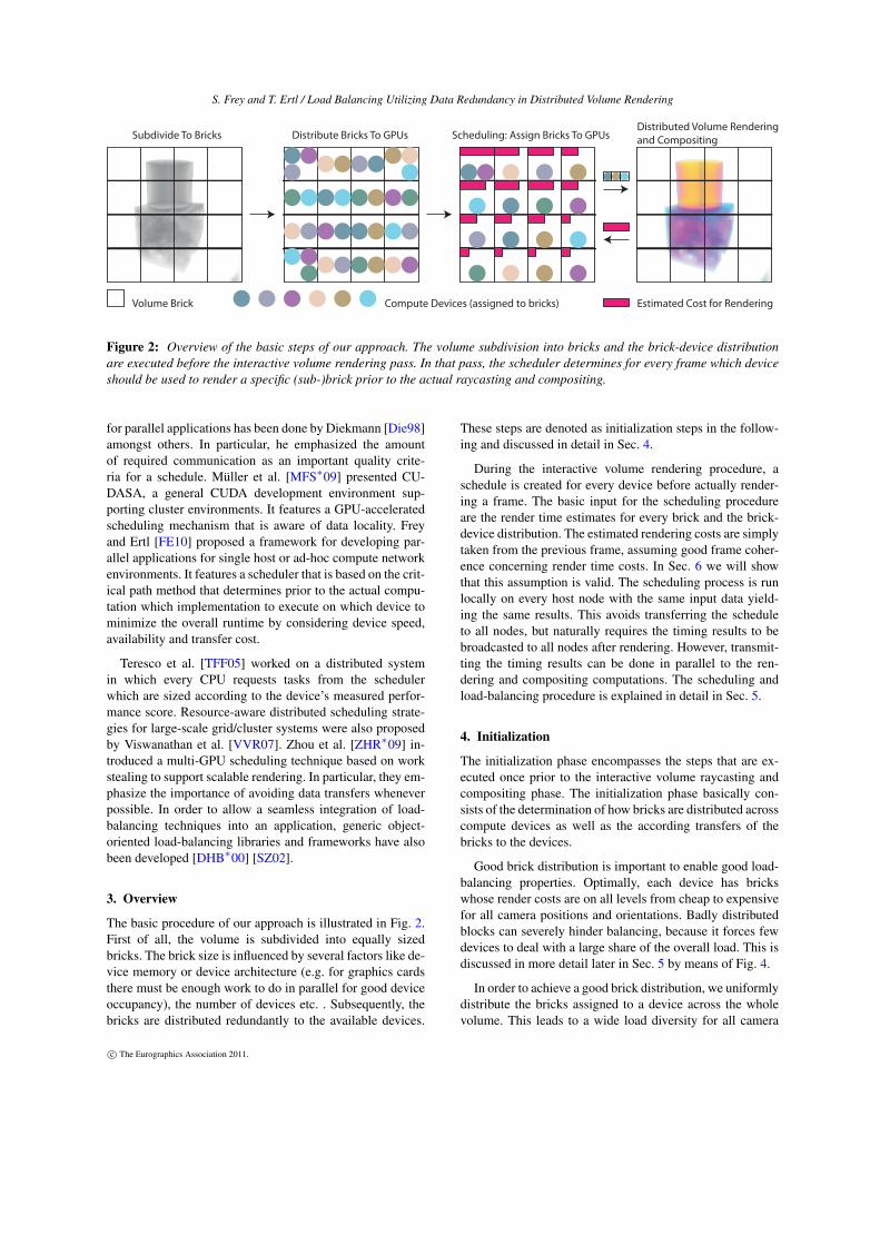
Figure 2: Overview of the basic steps of our approach. The volume subdivision into bricks and the brick-device distributionare executed before the interactive volume rendering pass. In that pass, the scheduler determines for every frame which deviceshould be used to render a specific (sub-)brick prior to the actual raycasting and compositing.
for parallel applications has been done by Diekmann [Die98]amongst others. In particular, he emphasized the amountof required communication as an important quality crite-ria for a schedule. Müller et al. [MFS∗09] presented CU-DASA, a general CUDA development environment sup-porting cluster environments. It features a GPU-acceleratedscheduling mechanism that is aware of data locality. Freyand Ertl [FE10] proposed a framework for developing par-allel applications for single host or ad-hoc compute networkenvironments. It features a scheduler that is based on the crit-ical path method that determines prior to the actual compu-tation which implementation to execute on which device tominimize the overall runtime by considering device speed,availability and transfer cost.
Teresco et al. [TFF05] worked on a distributed systemin which every CPU requests tasks from the schedulerwhich are sized according to the device’s measured perfor-mance score. Resource-aware distributed scheduling strate-gies for large-scale grid/cluster systems were also proposedby Viswanathan et al. [VVR07]. Zhou et al. [ZHR∗09] in-troduced a multi-GPU scheduling technique based on workstealing to support scalable rendering. In particular, they em-phasize the importance of avoiding data transfers wheneverpossible. In order to allow a seamless integration of load-balancing techniques into an application, generic object-oriented load-balancing libraries and frameworks have alsobeen developed [DHB∗00] [SZ02].
3. Overview
The basic procedure of our approach is illustrated in Fig. 2.First of all, the volume is subdivided into equally sizedbricks. The brick size is influenced by several factors like de-vice memory or device architecture (e.g. for graphics cardsthere must be enough work to do in parallel for good deviceoccupancy), the number of devices etc. . Subsequently, thebricks are distributed redundantly to the available devices.
These steps are denoted as initialization steps in the follow-ing and discussed in detail in Sec. 4.
During the interactive volume rendering procedure, aschedule is created for every device before actually render-ing a frame. The basic input for the scheduling procedureare the render time estimates for every brick and the brick-device distribution. The estimated rendering costs are simplytaken from the previous frame, assuming good frame coher-ence concerning render time costs. In Sec. 6 we will showthat this assumption is valid. The scheduling process is runlocally on every host node with the same input data yield-ing the same results. This avoids transferring the scheduleto all nodes, but naturally requires the timing results to bebroadcasted to all nodes after rendering. However, transmit-ting the timing results can be done in parallel to the ren-dering and compositing computations. The scheduling andload-balancing procedure is explained in detail in Sec. 5.
4. Initialization
The initialization phase encompasses the steps that are ex-ecuted once prior to the interactive volume raycasting andcompositing phase. The initialization phase basically con-sists of the determination of how bricks are distributed acrosscompute devices as well as the according transfers of thebricks to the devices.
Good brick distribution is important to enable good load-balancing properties. Optimally, each device has brickswhose render costs are on all levels from cheap to expensivefor all camera positions and orientations. Badly distributedblocks can severely hinder balancing, because it forces fewdevices to deal with a large share of the overall load. This isdiscussed in more detail later in Sec. 5 by means of Fig. 4.
In order to achieve a good brick distribution, we uniformlydistribute the bricks assigned to a device across the wholevolume. This leads to a wide load diversity for all camera
c© The Eurographics Association 2011.

S. Frey and T. Ertl / Load Balancing Utilizing Data Redundancy in Distributed Volume Rendering
(a) Initial Random Distribution (b) Optimized Distribution
Figure 3: Initialization of bricks (squares) with devices(colored circles). The optimized version is reorganized suchthat the distance of the bricks belonging to one device in-creases.
parameter settings in the rendering process. We define thecriteria for a good brick distribution as follows:
(a) Each device holds the maximum amount of bricks de-pending on its memory capacity.
(b) All bricks should be distributed about the same numberof times whenever possible.
(c) Any two devices do not share a large amount of associ-ated bricks.
(d) The minimum distance of the bricks assigned to a deviceis as big as possible.
The process to approach such a distribution is split intotwo steps as illustrated in Fig. 3. First, the bricks are dis-tributed randomly, taking care of conditions (a), (b) and (c).Second, the brick distribution is optimized regarding condi-tion (d) by swapping bricks between devices.. We will elab-orate on these steps in detail in the following.
Brick Distribution Initialization
The goal of this step is to determine a fair initial distri-bution of bricks to devices. In this context fair means thatinitially every brick has the same chances to be assigned toany device and that it is attempted to distribute bricks equallyoften.
First of all, the list of the devices and the list of bricks isshuffled randomly. Then, a brick and a device index are usedto iterate over the respective lists. In every iteration step, it isattempted to add the current brick to the current device. If itwas successful (i.e. the brick has not already been assignedto the device previously), both indices are incremented. Inthe case of an index reaching the end of a list, the respectivelist is shuffled and the index is set to the beginning of thatlist.
If a brick cannot be added to device, the index of the brickstays the same and only the device index is incremented.When the device index reaches its original index again (i.e.the brick could not be assigned to any device), the brick is
shuffle ( devices )shuffle ( bricks )b=0d=0while ( ! devices . empty( ) && ! bricks . empty( ) ) {
/ / brick i s inserted i f i t i s not present alreadyinserted = deviceBricks [ devices [d ] ] . inser t ( bricks [b] )i f ( inserted ) {
b++i f ( devices [d ] . size ( ) == devices [d ] . capacity ( ) ) {
/ / device i s f u l l −> delete i t from l i s tdevices . erase (d)d−−
}}else {
/ / brick insert ion pending i f d != −1i f (d == attemptingInsertSince ) {
/ / delete brick ,/ / i t cannot be inserted anywhere anymorebricks . erase (b)
}else i f (d == −1){
/ / s tar t a new attempt to add the brick/ / to the next possible deviceattemptingInsertSince = d
}}d++i f (d == devices . size ( ) ) {
d=0i f ( attemptingInsertSince == −1) {
/ / shuf f le devices i f there is/ / no pending brick insert ion attemptshuffle ( devices )
}}i f (b == bricks . size ( ) ) {
b=0shuffle ( bricks )
}}
Listing 1: Pseudo-code for initializing bricks with devices.
deleted from the list. Note that while a brick is in such apending state, the device vector is not shuffled.
Devices are erased from the device list when they reachtheir maximum brick reception capacity. The initializationis complete when either the brick list or the device list isempty. The procedure is outlined in more detail by means ofpseudo-code in Listing 1.
Brick Distribution Optimization
In the second step, devices swap bricks to optimize thebrick distribution. The basic procedure of this step bears
c© The Eurographics Association 2011.

S. Frey and T. Ertl / Load Balancing Utilizing Data Redundancy in Distributed Volume Rendering
22.3%
0
19.3%
1
12.3%
2
1.7%
3
29.2%
4
9.6%
5
0.0%
6
0.0%
7
5.3%
8
0.0%
9
0.0%
10
0.0%
11
0.0%
12
0.0%
13
0.0%
14
0.0%
15 0
22.3
0
1
19.3
1
107
2
5.3
81411
3
29.2
4
4
22.0
2
5
13
5
1.73 615 129
(a) No Job Splitting
2.7%02.7%1
2.7%22.7%3
2.7%42.7%5
2.7%62.7%7
2.4%82.4%9
2.4%102.4%11
2.4%122.4%13
2.4%142.4%15
3.0%16
3.0%17
3.0%18
3.0%19
1.7%
203.6%213.6%22
3.6%233.6%24
3.6%253.6%26
3.6%273.6%28
2.4%29
2.4%30
2.4%31
2.4%32
0.0%
33
0.0%
34
2.6%35
2.6%36
0.0%
37
0.0%
38
0.0%
39
0.0%
40
0.0%
41
0.0%
42
0.0%
43 0
12.3
19
18
17
16 3442
1
22.2
36
35
89101113
1429
2
12.8
7
5
3
12039
3
19.4
24
26
28
22
121538 41
4
21.8
25
27
23
21
323130
5
11.2
6
4
2033374043
(b) With Job Splitting
Figure 4: Splitting jobs improves the balancing of load across devices with certain camera configurations. Note that theassignment of bricks to devices is the same as in Fig. 1.
some similarity with the point swapping procedure em-ployed by Balzer et al. [BSD09] for optimizing point clus-ters. For each pair of devices, the most beneficial pair ofbricks to swap between them is determined and subsequentlyexchanged if the status quo is improved by that. A swap isonly valid when there are no brick duplicates on a device asa result.
The quality of the distribution of bricks B(d) for a deviced is measured by the quality function q:
q(d) = ∑b0∈B(d)
∑b1∈B(d)
√|b0−b1| (1)
Using the square root of all brick pairs as quality measure isuseful for our purpose as – in opposite to squared distances –many small uniform distances lead to a much higher valuethan only one far away brick. This means that the maximiza-tion of the measure q leads to a wide and largely uniformbrick distribution. The optimization step ends when all pos-sible device pairs have been looked at without inducing aswap.
5. Load-Balancing
After the initialization step, every device has a number ofbricks assigned to it that it can render potentially. For everyframe, it is determined which device to use for rendering acertain brick. This process is split into two steps: the subdi-vision of the bricks to render jobs and the scheduling of thejobs such that the overall execution time is minimized. Thejob generation process bears some similarity to traditionalload balancing in parallel volume rendering as it has beendiscussed in Sec. 2. However, in contrast to these techniques,the amount of partitions is not bound to the amount of de-vices. In the end, this makes the (brick) partitioning easierbecause it is sufficient to distribute the load of the brick onlyapproximately to jobs and then balance the load by smartlyassigning multiple jobs to devices.
5.1. Job Generation
Originally, every brick rendering task translates into one job.A good balancing of load between devices can be achieved
while ( ! stable ) {stable = truefor d0 in devices {
for d1 in devices {baseQuality = quality ( bricksAssignedTo (d0))
+ quali ty ( bricksAssignedTo (d1) )bestQuality = baseQuality
/ / swap al l possible brick pairs and/ / measure qualityfor b0 in bricksAssignedTo (d0) {
for b1 in bricksAssignedTo (d1) {tmp0 = bricksAssignedTo (d0)tmp0. erase (b0)i f ( ! tmp0. inser t (b1) )
/ / b1 is already in assigned to d0continue
tmp1 = bricksAssignedTo (d1)tmp1. erase (b1)i f ( ! tmp1. inser t (b0) )
/ / b0 is already in assigned to d1continue
/ / determine most beneficial brick swapi f ( quali ty (tmp0) + quality (tmp1) > baseQuality ) {
bestQuality = quality (tmp0) + quality (tmp1)bestSwap = (b0 ,b1)
}}
}/ / swap most beneficial pair of bricks/ / i f i t s bet ter than the status quoi f ( bestQuality > baseQuality ) {
bricksAssignedTo (d0 ) . erase (bestSwap[0])bricksAssignedTo (d1 ) . erase (bestSwap[1])bricksAssignedTo (d0 ) . inser t (bestSwap[1])bricksAssignedTo (d1 ) . inser t (bestSwap[0])stable = false
}}
}}
Listing 2: Pseudo-code for optimizing brick assignments.
c© The Eurographics Association 2011.

S. Frey and T. Ertl / Load Balancing Utilizing Data Redundancy in Distributed Volume Rendering
that way when the major rendering load is distributed acrossmany bricks (like in Fig. 1 for instance). However, when therendering of only one or very few bricks constitutes the ma-jor share of the overall cost, the bricks need to be split toallow for equal load distribution (Fig. 4).
This is accomplished by looping over all jobs from theprevious frame and splitting them recursively until eachjob’s estimated rendering cost exceeds a certain value a:
a = max(
∑ j∈Jobs c( j)|D| ·b2 ,r
)(2)
c( j) The anticipated cost of a job.|D| The number of devices.b The maximal amount of redundant copies
of any brick.r Lower bound for job render time.
The lower bound r for a is determined experimentally –we used 5 ms for the measurements in the context of thiswork. It is motivated from the fact that parallel devices ingeneral and GPUs in particular (our targeted compute de-vice in this work) need a certain amount of work (i.e. de-gree of parallelism) to work efficiently. In extreme cases,low GPU occupancy could lead to a scenario in which eachof two newly generated jobs takes as long as the original jobwould have. The maximum amount of redundant copies b isused to express the number of options the scheduler has tochoose a device for a certain job. In particular if there aremany options for a scheduler, numerous smaller instead offew big jobs are useful because this enables the scheduler todistribute the load more finely. In contrast to that, if a job canonly be assigned to one specific device, it makes no sense tosplit it and cause unnecessary execution overhead.
Before rendering the very first frame, each brick is initial-ized with its own binary tree, only consisting of the anchornode at first. The leaves of this tree represent the jobs thatare associated with the respective brick. The job cost esti-mates are set to the same, arbitrary value due to the lack ofreal rendering timing results initially. Starting from the sec-ond frame, every leaf of the tree is assigned the renderingtime estimated for it. In our case, this is simply the render-ing cost that its associated job had in the previous frame. InSection 6, we will show that this assumption is valid at leastfor our application scenario. Based on the estimated costs forits leaves, the tree of each brick is modified per frame in twoconsecutive phases: the splitting and the merging phase.
In the splitting phase, if the cost estimate for a leaf ex-ceeds a, the volume block associated with it is split in halfand two child nodes are created representing the two newvolume blocks. Each of the children is assigned half of theestimated cost of its parent node. Splitting is performed axisaligned such that the resulting jobs or leaves are equallybig (i.e. their associated volume blocks have the same size).The split axis is chosen such that the length of the diagonal
of the volume blocks attached to the jobs is minimal. Thisachieves a good trade-off between resulting image size thatneeds to be transferred for scheduling (smaller image-spacefootprint is better) and the amount of casted rays for goodoccupancy (larger image-space footprint is better). When alledge lengths are equal, we split along the axis that is mostaligned with the view direction.
When the camera position or focus changes, renderingcosts change as well and previously split jobs might needto be merged again in order to avoid unnecessary overhead.To this end we iterate over all sibling pairs of jobs (they weresplit from the same job in a previous frame) and determinewhether the sum of their cost estimates still meets the split-ting criteria. If this is not the case, they are merged backagain to one job, which means that they are removed fromthe tree and their total weight is assigned to the parent node.This procedure is executed recursively for all leaf nodes untilthe sums of all leaf siblings exceed a.
5.2. Job Scheduling
The task of a scheduler is to decide in every frame what jobsa device needs to render such that every brick is renderedexactly once and the maximum load occurring on any devicein minimal. Formally, this is an optimization problem that isclosely related to the class of packing problems. It can bedefined as follows:
Given: A set of devices D, a set of jobs J and a functionc : D× J→ R∪∞.
Find: A surjective assignment function a : D→ J such thatmaxd∈D(∑ j∈a(d) c(d, j)) is minimal.
Note that c(d, j) =∞ if the brick belonging to the job j ∈ Jis not present on device d ∈ D. Alternatively, depending onthe application, it can be useful to use a sufficiently largeconstant C instead (i.e. such that C is safely larger than anypossible device fill level). This would trigger the additionalassignment of bricks in cases in which a brick has not beenassigned to any device initially.
As our scheduler needs to be run for every frame and thusneeds to be fast, we do not attempt to solve this complexproblem optimally. Instead, we opted for a quick and simpleapproach that still delivers good results. It bears some sim-ilarities to the best-fit decreasing heuristic that can be usedfor the bin packing problem and basically works as follows:
1. Sort all jobs in order of their weight in descending order2. Iterate through the job list and assign each job to a device
such that the overall estimated execution time of all jobsof a device across all devices is minimal.
The overall complexity of the algorithm is O(n logn+ nd).While sorting is in O(n logn) with n being the number ofjobs, the job assignment procedure is in O(nd), with d de-noting the number of devices assigned to a brick. A completeexample on the output produced by the scheduler for a spe-cific input is provided in Fig. 1 and Fig. 4.
c© The Eurographics Association 2011.
S. Frey and T. Ertl / Load Balancing Utilizing Data Redundancy in Distributed Volume Rendering
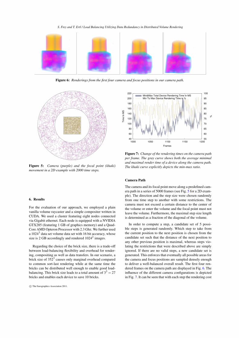
Figure 6: Renderings from the first four camera and focus positions in our camera path.
Figure 5: Camera (purple) and the focal point (khaki)movement in a 2D example with 2000 time steps.
6. Results
For the evaluation of our approach, we employed a plainvanilla volume raycaster and a simple compositer written inCUDA. We used a cluster featuring eight nodes connectedvia Gigabit ethernet. Each node is equipped with a NVIDIAGTX285 (featuring 1 GB of graphics memory) and a Quad-Core AMD Opteron Processor with 2.3 Ghz. We further useda 10243 data set volume data set with 16 bit accuracy, whosesize is 2 GB accordingly and rendered 10242 images.
Regarding the choice of the brick size, there is a trade-offbetween load-balancing flexibility and overhead for render-ing, compositing as well as data transfers. In our scenario, abrick size of 3523 causes only marginal overhead comparedto common sort-last rendering while at the same time thebricks can be distributed well enough to enable good load-balancing. This brick size leads to a total amount of 33 = 27bricks and enables each device to save 10 bricks.
40
60
80
100
120
140
160
180
200
220
1000 1050 1100 1150 120055
60
65
70
75
80
85
90
95
100
TimeInMS
%
Frames
Min&Max Total Device Rendering Time In MSMin To Max Device Rendering Time in %
Figure 7: Change of the rendering times on the camera pathper frame. The gray curve shows both the average minimaland maximal render time of a device along the camera path.The khaki curve explicitly depicts the min-max ratio.
Camera Path
The camera and its focal point move along a predefined cam-era path in a series of 5000 frames (see Fig. 5 for a 2D exam-ple). The direction and the step size were chosen randomlyfrom one time step to another with some restrictions. Thecamera must not exceed a certain distance to the center ofthe volume or enter the volume and the focal point must notleave the volume. Furthermore, the maximal step size lengthis determined as a fraction of the diagonal of the volume.
In order to compute a step, a candidate set of 5 possi-ble steps is generated randomly. Which step to take fromthe current position to the next position is chosen from thecandidate set such that the distance of the next position toany other previous position is maximal, whereas steps vio-lating the restrictions that were described above are simplyignored. If there are no valid steps, a new candidate set isgenerated. This enforces that eventually all possible areas forthe camera and focus positions are sampled densely enoughto deliver a well-balanced overall result. The first four ren-dered frames on the camera path are displayed in Fig. 6. Theinfluence of the different camera configurations is depictedin Fig. 7. It can be seen that with each step the rendering cost
c© The Eurographics Association 2011.

S. Frey and T. Ertl / Load Balancing Utilizing Data Redundancy in Distributed Volume Rendering
0
1
2
3
4
5
6
7
0 10 20 30 40 500
100
200
300
400
500
600
%
TimeInMS
Frames
Max Diff To Prev Frame (%)Avg Diff To Previous Frame (%)
Total Est./Real (Ms)Max SubVol Difference (Ms)
Figure 8: Comparison between estimated render time (ren-der time from previous frame) and real execution time for thefirst 50 frames of our camera path. The gray and the khakicurve express the difference relative to the previous valueson a percentage basis. While the khaki curve compares thetotal execution time of all jobs, the gray curve displays themaximum difference between any two jobs. The cyan curvegives both the total estimated and total measured renderingtime while the orange curve depicts the maximal time differ-ence between two jobs.
might change significantly. The magnitude of the changesmight even be less favorable in terms of frame coherencythan the average interactive volume rendering session. Still,as we will show in the following, the render times of theprevious frame are a good indication for the current frame.
Brick Rendering Predictions
It is critical for our application that there are good predic-tions on how expensive jobs are relative to each other for theupcoming frame. To that end we simply use the render timefrom the previous frame. Figure 8 shows that the assump-tion of coherent render times is valid for our scenario as therelative differences are within the range of a few percent.Obviously, if there were really large camera leaps betweentwo frames, the render times from the previous frame wouldnot be very expressive. However, these leaps usually do notoccur in systems with stable, interactive frame rates.
Scaling
The scaling behaviour of our approach with an increasingamount of devices is plotted in Fig. 9. It shows that themaximal render time per device profits significantly from anincrease in device count. Its scaling factor is even slightlylarger than one. For instance, the longest time any deviceneeds to render its bricks is 122.9 ms with four nodes and55.5 ms with eight nodes. The reason for that is that withmore devices more memory becomes available and the levelof redundancy rises. The increasing brick redundancy is also
0
20
40
60
80
100
120
140
160
180
3 4 5 6 7 80
20
40
60
80
100
120
140
160
180
TimeInMS
BrickRedundancy
Devices
Min&Max Total Device Rendering Time In MSMin-Max Diff in MsBrick RedundancyScaling Baseline
Figure 9: Scaling with the amount of compute devices. Thegray curve shows both the average minimal and maximalrender time of a device along the camera path. The khakicurve explicitly depicts the difference. The purple curveshows the increasing redundancy factor, meaning that bricksare distributed to more devices (see Eq. 3). The cyan curveshows the baseline scaling curve based on the performancewith three nodes.
plotted in Fig. 9. The redundancy factor is defined as
∑d∈D b(d)|B| (3)
with D being the set of devices, |B| the number of bricks andb(d) the amount of bricks stored on a device d ∈ D. Moreredundancy enables the scheduler to find a more optimaldevice-brick assignment. It also helps to decrease the max-imal load imbalance (i.e. the difference between the maxi-mum and minimum time taken for rendering by a device).
Brick Distribution Variations
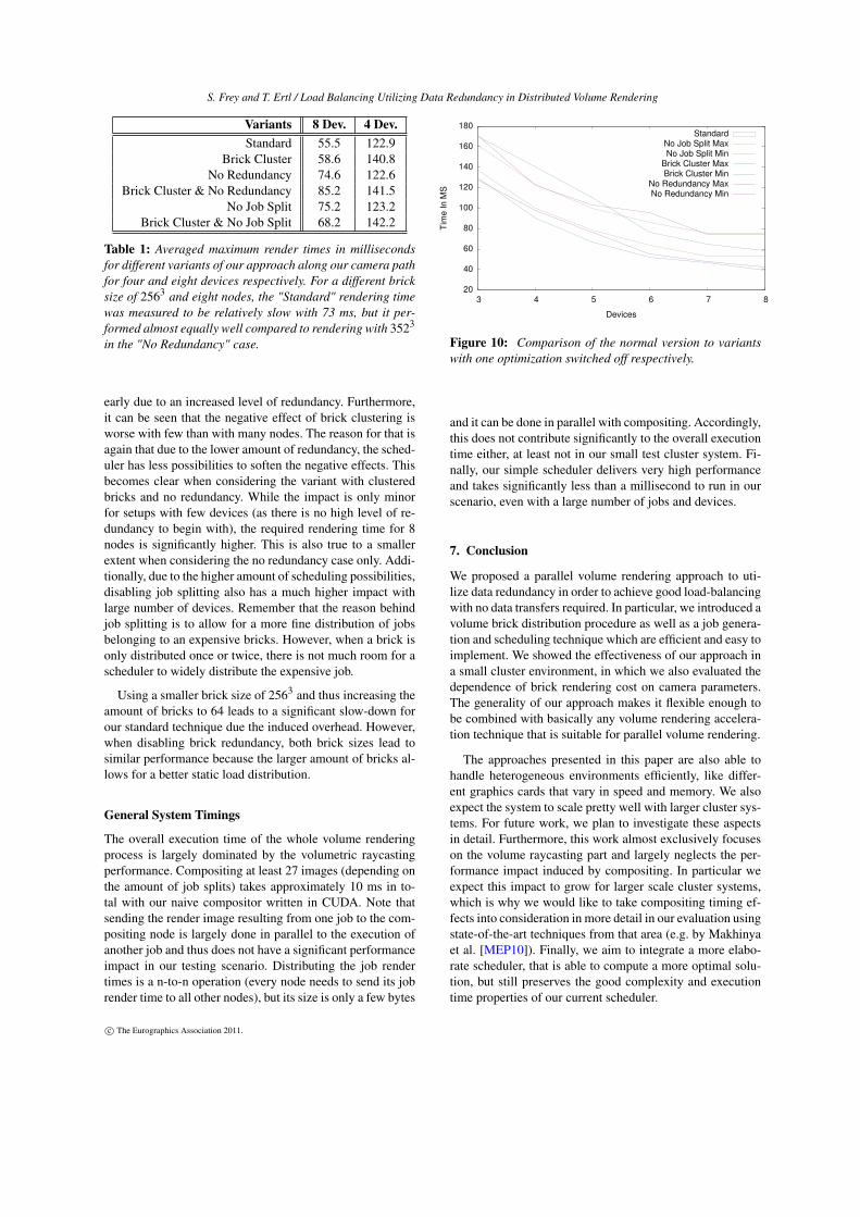
Our approach consists of a set of optimizations that can beenabled or disabled to study their benefit. It can be seen fromTable 1 and Fig. 10 that the improvement of using a certainoptimization heavily depends on the amount of devices thatare involved in the computation. The keywords in the figureand the table stand for the following optimization variants:
Standard The normal approach with every feature pre-sented in the paper.
No Redundancy Each brick is assigned one device only.Brick Cluster Bricks belonging to a device are not dis-
tributed across the volume but concentrated in one area.This is computed by using the inverse quality function inthe optimization step of the initial brick distribution (seeSec. 4). In combination with No Redundancy, this approx-imates the common one-brick-per-device strategy.
No Job Split Splitting of jobs into smaller jobs is disabled.This means that a brick translates into exactly one job.
The table shows the aforementioned effect that the tech-nique for the standard variant scales a little better than lin-
c© The Eurographics Association 2011.
S. Frey and T. Ertl / Load Balancing Utilizing Data Redundancy in Distributed Volume Rendering
Variants 8 Dev. 4 Dev.Standard 55.5 122.9
Brick Cluster 58.6 140.8No Redundancy 74.6 122.6
Brick Cluster & No Redundancy 85.2 141.5No Job Split 75.2 123.2
Brick Cluster & No Job Split 68.2 142.2
Table 1: Averaged maximum render times in millisecondsfor different variants of our approach along our camera pathfor four and eight devices respectively. For a different bricksize of 2563 and eight nodes, the "Standard" rendering timewas measured to be relatively slow with 73 ms, but it per-formed almost equally well compared to rendering with 3523
in the "No Redundancy" case.
early due to an increased level of redundancy. Furthermore,it can be seen that the negative effect of brick clustering isworse with few than with many nodes. The reason for that isagain that due to the lower amount of redundancy, the sched-uler has less possibilities to soften the negative effects. Thisbecomes clear when considering the variant with clusteredbricks and no redundancy. While the impact is only minorfor setups with few devices (as there is no high level of re-dundancy to begin with), the required rendering time for 8nodes is significantly higher. This is also true to a smallerextent when considering the no redundancy case only. Addi-tionally, due to the higher amount of scheduling possibilities,disabling job splitting also has a much higher impact withlarge number of devices. Remember that the reason behindjob splitting is to allow for a more fine distribution of jobsbelonging to an expensive bricks. However, when a brick isonly distributed once or twice, there is not much room for ascheduler to widely distribute the expensive job.
Using a smaller brick size of 2563 and thus increasing theamount of bricks to 64 leads to a significant slow-down forour standard technique due the induced overhead. However,when disabling brick redundancy, both brick sizes lead tosimilar performance because the larger amount of bricks al-lows for a better static load distribution.
General System Timings
The overall execution time of the whole volume renderingprocess is largely dominated by the volumetric raycastingperformance. Compositing at least 27 images (depending onthe amount of job splits) takes approximately 10 ms in to-tal with our naive compositor written in CUDA. Note thatsending the render image resulting from one job to the com-positing node is largely done in parallel to the execution ofanother job and thus does not have a significant performanceimpact in our testing scenario. Distributing the job rendertimes is a n-to-n operation (every node needs to send its jobrender time to all other nodes), but its size is only a few bytes
20
40
60
80
100
120
140
160
180
3 4 5 6 7 8
TimeIn
MS
Devices
StandardNo Job Split MaxNo Job Split Min
Brick Cluster MaxBrick Cluster Min
No Redundancy MaxNo Redundancy Min
Figure 10: Comparison of the normal version to variantswith one optimization switched off respectively.
and it can be done in parallel with compositing. Accordingly,this does not contribute significantly to the overall executiontime either, at least not in our small test cluster system. Fi-nally, our simple scheduler delivers very high performanceand takes significantly less than a millisecond to run in ourscenario, even with a large number of jobs and devices.
7. Conclusion
We proposed a parallel volume rendering approach to uti-lize data redundancy in order to achieve good load-balancingwith no data transfers required. In particular, we introduced avolume brick distribution procedure as well as a job genera-tion and scheduling technique which are efficient and easy toimplement. We showed the effectiveness of our approach ina small cluster environment, in which we also evaluated thedependence of brick rendering cost on camera parameters.The generality of our approach makes it flexible enough tobe combined with basically any volume rendering accelera-tion technique that is suitable for parallel volume rendering.
The approaches presented in this paper are also able tohandle heterogeneous environments efficiently, like differ-ent graphics cards that vary in speed and memory. We alsoexpect the system to scale pretty well with larger cluster sys-tems. For future work, we plan to investigate these aspectsin detail. Furthermore, this work almost exclusively focuseson the volume raycasting part and largely neglects the per-formance impact induced by compositing. In particular weexpect this impact to grow for larger scale cluster systems,which is why we would like to take compositing timing ef-fects into consideration in more detail in our evaluation usingstate-of-the-art techniques from that area (e.g. by Makhinyaet al. [MEP10]). Finally, we aim to integrate a more elabo-rate scheduler, that is able to compute a more optimal solu-tion, but still preserves the good complexity and executiontime properties of our current scheduler.
c© The Eurographics Association 2011.
S. Frey and T. Ertl / Load Balancing Utilizing Data Redundancy in Distributed Volume Rendering
References[BSD09] BALZER M., SCHLÖMER T., DEUSSEN O.: Capacity-
constrained point distributions: A variant of Lloyd’s method.ACM Transactions on Graphics (Proceedings of SIGGRAPH) 28,3 (2009), 86:1–8. 5
[DHB∗00] DEVINE K., HENDRICKSON B., BOMAN E., JOHNM. S., VAUGHAN C.: Design of dynamic load-balancing toolsfor parallel applications. In Proc. Intl. Conf. on Supercomputing(Santa Fe, New Mexico, 2000), pp. 110–118. 3
[Die98] DIEKMANN R.: Load Balancing Strategies for Data Par-allel Applications. PhD thesis, UniversitÃd’t Paderborn, 1998. 3
[FE10] FREY S., ERTL T.: PaTraCo: A Framework Enabling theTransparent and Efficient Programming of Heterogeneous Com-pute Networks. Ahrens J., Debattista K., Pajarola R., (Eds.), Eu-rographics Association, pp. 131–140. 3
[FK09] FRANK S., KAUFMAN A.: Dependency graph approachto load balancing distributed volume visualization. The VisualComputer 25, 4 (2009), 325–337. 2
[KW03] KRÜGER J., WESTERMANN R.: Acceleration Tech-niques for GPU-based Volume Rendering. In Proceedings ofIEEE Visualization ’03 (2003), pp. 287–292. 2
[LSH05] LEE W.-J., SRINI V., HAN T.-D.: Adaptive and Scal-able Load Balancing Scheme for Sort-Last Parallel Volume Ren-dering on GPU Clusters. In International Workshop on VolumeGraphics (2005). 2
[MCEF94] MOLNAR S., COX M., ELLSWORTH D., FUCHS H.:A sorting classification of parallel rendering. IEEE ComputerGraphics and Applications 14, 4 (1994), 23–32. 2
[MEP10] MAKHINYA M., EILEMANN S., PAJAROLA R.: FastCompositing for Cluster-Parallel Rendering. Ahrens J., Debat-tista K., Pajarola R., (Eds.), Eurographics Association, pp. 111–120. 9
[MFS∗09] MÜLLER C., FREY S., STRENGERT M., DACHS-BACHER C., ERTL T.: A compute unified system architecture forgraphics clusters incorporating data locality. IEEE Transactionson Visualization and Computer Graphics 15, 4 (2009), 605–617.3
[MHE01] MAGALLÒN M., HOPF M., ERTL T.: Parallel volumerendering using PC graphics hardware. In Pacific Conference onComputer Graphics and Applications (2001), pp. 384–389. 2
[MMD06] MARCHESIN S., MONGENET C., DISCHLER J.-M.:Dynamic Load Balancing for Parallel Volume Rendering. In Eu-rographics Symposium on Parallel Graphics and Visualization(2006), Eurographics Association, pp. 51–58. 2
[MPHK93] MA K. L., PAINTER J. S., HANSEN C. D., KROGHM. F.: A Data Distributed, Parallel Algorithm for Ray-TracedVolume Rendering. In PRS ’93: Proceedings of the 1993 Sympo-sium on Parallel Rendering (1993), pp. 15–22. 2
[MSE06] MÜLLER C., STRENGERT M., ERTL T.: OptimizedVolume Raycasting for Graphics-Hardware-based Cluster Sys-tems. In Eurographics Symposium on Parallel Graphics and Vi-sualization (2006), Eurographics Association, pp. 59–66. 2
[Neu93] NEUMANN U.: Parallel Volume-Rendering AlgorithmPerformance on Mesh-Connected Multicomputers. In PRS ’93:Proceedings of the 1993 Symposium on Parallel Rendering(1993), pp. 97–104. 2
[NVI08] NVIDIA: NVIDIA CUDA SDK code samples.http://developer.nvidia.com/object/cuda.html, 2008. 2
[PRY∗08] PETERKA T., ROSS R., YU H., MA K.-L., KENDALLW., HUANG J.: Assessing improvements in the parallel volumerendering pipeline at large scale. In Proceedings of SC 08 Ultra-scale Visualization Workshop (Austin TX, 2008). 2
[PTT97] PALMER M. E., TAYLOR S., TOTTY B.: Exploitingdeep parallel memory hierarchies for ray casting volume render-ing. In Proceedings of the IEEE symposium on Parallel rendering(New York, NY, USA, 1997), PRS ’97, ACM, pp. 15–ff. 2
[PYRM08] PETERKA T., YU H., ROSS R., MA K.-L.: Parallelvolume rendering on the ibm blue gene/p. In Proc. Eurograph-ics Parallel Graphics and Visualization Symposium 2008 (2008),pp. 73–80. 2
[SSKE05] STEGMAIER S., STRENGERT M., KLEIN T., ERTLT.: A Simple and Flexible Volume Rendering Framework forGraphics-Hardware–based Raycasting. In Proceedings of the In-ternational Workshop on Volume Graphics ’05 (2005), pp. 187–195. 2
[SZ02] STANKOVIC N., ZHANG K.: A distributed parallel pro-gramming framework. IEEE Trans. Softw. Eng. 28, 5 (2002),478–493. 3
[TFF05] TERESCO J. D., FAIK J., FLAHERTY J. E.: Resource-aware scientific computation on a heterogeneous cluster. Com-puting in Science and Engineering 7, 2 (2005), 40–50. 3
[VVR07] VISWANATHAN S., VEERAVALLI B., ROBERTAZZIT. G.: Resource-aware distributed scheduling strategies forlarge-scale computational cluster/grid systems. IEEE Trans. Par-allel Distrib. Syst. 18, 10 (2007), 1450–1461. 3
[WGS04] WANG C., GAO J., SHEN H.-W.: Parallel Multireso-lution Volume Rendering of Large Data Sets with Error-GuidedLoad Balancing. In Eurographics Symposium on Parallel Graph-ics and Visualization (2004), pp. 23–30. 2
[WPLM01] WYLIE B., PAVLAKOS C., LEWIS V., MORELANDK.: Scalable rendering on pc clusters. IEEE Comput. Graph.Appl. 21 (July 2001), 62–70. 2
[ZHR∗09] ZHOU K., HOU Q., REN Z., GONG M., SUN X.,GUO B.: Renderants: interactive reyes rendering on gpus. InSIGGRAPH Asia ’09: ACM SIGGRAPH Asia 2009 papers (NewYork, NY, USA, 2009), ACM, pp. 155:1–11. 3
c© The Eurographics Association 2011.