lng terminal in Świnoujście marine operations...
TRANSCRIPT

No. PE-PP-10-1 – Rev. 2.5 Page 1 of 142
LNG Terminal in Świnoujście
Marine Operations Manual
PE-PP-10-1

No. PE-PP-10-1 – Rev. 2.5 Page 2 of 142
Characteristics, issues, distribution and revisions of the document
Document characteristics
Subject area Marine Operations
Category
Concept owner
Elaborated by (date & name) 25.03.2014, Adam Łupkowski, Maciej
Gucma
Checked by (scope, date & name) Marcin Palczyński
Verified by (scope, date & name) Jacek Banaszek
Approved by (scope, date & name) Janusz Kurmański
Related internal regulations
Terminal Service Manual, Operating
Manual – Unloading System (10), LNG
Carrier Approval Procedure
Classification
Document issues
Issue No. Issue date Distribution
Original Copy 1 Copy 2 Copy 3
1.0 25.03.2014
2.0 08.01.2015
Revisions – updates, reviews, audits
Rev.
No.
Effective
date
Scope of update, review, inspection
Description of modification / amendment Date & name (author)
1.0 25.04.14
Incorporation of Maritime Office’s comments
comprised in letter ref. Kpe-II-
63207/54/6/3/14.
25.04.14 Adam
Łupkowski, Maciej
Gucma
1.1 29.05.14 Incorporation of Maritime Office’s comments
following consultation on 23.05.14 & 29.05.14
29.05.14 Adam
Łupkowski
1.2 30.05.14
Positive Validation by Maritime Office
comprised in letter ref. Kpe-ll -63207/541 651/I
4.
30.05.14 Adam
Łupkowski
2.0 08.01.15 Technical validation based on LNG supplier’s
feedback.
08.01.15 Adam
Łupkowski
2.1 16.09.15 Technical validation based on DNV GL
verification report.
16.09.15 Adam
Łupkowski
2.2 12.11.15 Mooring system upgrade to 20 hooks
configuration.
12.11.15 Adam
Łupkowski

No. PE-PP-10-1 – Rev. 2.5 Page 3 of 142
2.3 20.04.16 Mooring system upgrade to 22 hooks
configuration.
20.04.16 Adam
Łupkowski
2.4 05.07.16
Wind speed limit for cargo operations
increased from 12,5 m/s to 15 m/s based on
comprehensive technical studies carried out
by Maritime University of Szczecin.
05.07.2016 Adam
Łupkowski
2.5 18.08.16
Wind speed limit for cargo arms
disconnection estbilished at 17,5 m/s based
on comprehensive technical studies carried
out by Maritime University of Szczecin.
18.08.16 Adam
Łupkowski

No. PE-PP-10-1 – Rev. 2.5 Page 4 of 142
Contact with PLNG S.A.
Terminal address:
Marine LNG Terminal
PLNG S.A.
ul. Ku Morzu
72-602 Świnoujście
e-mail:
Company seat:
Polskie LNG S.A.
ul. Fińska 7
72-602 Świnoujście
e-mail:

No. PE-PP-10-1 – Rev. 2.5 Page 5 of 142
Table of contents
Characteristics, issues, distribution and revisions of the document ..................................... 2
A. Introduction ............................................................................................................................... 9
B. Goal of this document ......................................................................................................... 10
C. General information .............................................................................................................. 11
C.1 Description of the terminal; ........................................................................................... 11
C.2 Location; ............................................................................................................................. 12
C.3 Hydrometeorological conditions; ................................................................................ 12
C.4 Charts and nautical publications: ............................................................................... 16
C.5 Requirements concerning tugs .................................................................................... 17
C.6 Requirements concerning fire-fighting ship .............................................................. 21
C.7 Requirements concerning the notification of arrival of the LNG carrier at the terminal ........................................................................................................................................... 21
D. Terminal safety regulations and policy ............................................................................ 25
D.1 Restricted access zone around the LNG carrier. .................................................... 25
D.2 Consequences of breaching the terminal security rules ...................................... 25
D.3 Reference to the health and safety and environmental protection rules in force at the terminal ................................................................................................................... 26
D.4 Reference to safety regulations and checklists (ISGOTT 5th edition) ................ 27
D.5 Rules concerning the persons visiting the ship ......................................................... 28
D.6 Terminal drug and alcohol policy ............................................................................... 29
E. Procedures of entry into the outer port in Świnoujście – PE-PP-10-1-1 .................... 29
E.1 General information concerning the commercial port in Świnoujście. ........... 30
E.2 The approach fairway, available anchorages and rules of their use by LNG
carriers ............................................................................................................................................. 30
E.3 Communication with Maritime Administration ........................................................ 33
E.4 Communication between the ship and terminal operator ................................. 36
E.5 SSI & Vessel Compatibility Study .................................................................................. 37
E.6 Condition of ship tanks and cargo system upon arrival. ...................................... 40
E.7 Information on pilot services ......................................................................................... 40
E.8 "Master/Pilot Exchange” checklist ............................................................................... 43
E.9 Conclusions of the FMBS ................................................................................................ 44
F. Berth approach, mooring and berthing procedures – PE-PP-10-1-2....................... 47
F.1 Operational limits of the terminal (permissible carrier parameters) .................. 47

No. PE-PP-10-1 – Rev. 2.5 Page 6 of 142
F.2 Maximum allowed hydrometeorological conditions during
entrance/departure from the port ......................................................................................... 48
F.3 Port Regulations requirements for mooring assistance ......................................... 49
F.4 Terminal Operator requirements for mooring assistance and berth equipment 50
F.5 Berth equipment ............................................................................................................... 53
F.6 International Shore Connection .................................................................................. 53
F.7 Taking provisions and stores by the ship .................................................................... 53
F.8 Bunkering ............................................................................................................................ 54
F.9 Repairs ................................................................................................................................. 54
F.10 Managing ballast water ................................................................................................. 54
F.11 Wastewater and waste disposal rules ........................................................................ 54
F.12 Shore leave ........................................................................................................................ 55
F.13 Preparation of the berth for the LNG carrier in winter conditions ...................... 55
G. Cargo operations – PE-PP-10-1-3 ....................................................................................... 56
G.1 General information ........................................................................................................ 56
G.2 Supervision over the operation and division of responsibilities ........................... 57
G.3 Gangway positioning ...................................................................................................... 59
G.4 LNG unloading procedure and pre-discharge meeting ...................................... 60
G.5 Connection of unloading and BOG return arms .................................................... 62
G.6 Leak test and pressure test ............................................................................................ 62
G.7 Preliminary CTMS measurement. ................................................................................. 62
G.8 BOG handling system configuration ........................................................................... 63
G.9 "Warm ESD” test ................................................................................................................ 63
G.10 Unloading arm and line cool-down ........................................................................ 64
G.11 "Cold ESD” test .............................................................................................................. 64
G.12 Unloading commencement and control ............................................................. 64
G.13 Cargo sampling ............................................................................................................ 65
G.14 Unloading completion ................................................................................................ 65
G.15 Drainage and nitrogen purge of unloading arms .............................................. 65
G.16 Final CTMS measurement and post-discharge meeting. ................................. 67
G.17 Disconnection of unloading and BOG return arms ............................................ 67
G.18 Post-discharge documentation ............................................................................... 68
H. Emergency procedures – PE-PP-10-1-4 ............................................................................ 68
H.1 Source regulations and industry guidelines .............................................................. 68
H.2 Introduction........................................................................................................................ 68
H.3 Goal of this section .......................................................................................................... 69

No. PE-PP-10-1 – Rev. 2.5 Page 7 of 142
H.4 Range .................................................................................................................................. 69
H.5 Emergency situations within the berth ....................................................................... 75
H.6 Emergency situations on the LNG tanker .................................................................. 78
H.7 Detection of an emergency situation by the ship at the berth .......................... 81
H.8 Evacuation of the ship and evacuation of the LNG unloading platform ....... 82
I. List of contacts ........................................................................................................................ 85
J. Appendices. ............................................................................................................................ 89
J.1 Appendix No. 1 – List of documents – PE-PP-10-1-W1 ............................................ 89
J.2 Appendix No. 2 – SSSCL with filling instruction – PE-PP-10-1-F-1 ........................... 91
J.3 Appendix No. 3 Checklist – Pre-discharge meeting – PE-PP-10-1-F-2.............. 108
J.4 Appendix No. 4 – Safety Letter – PE-PP-10-1-F-4 .................................................... 110
J.5 Appendix No. 5 – Marine Operations Algorithm – PE-PP-10-1-Z-1 .................... 111
J.6 Appendix No. 6 Notification of Departure from the Port of Loading – PE-PP-10-
1-F5 112
J.7 Appendix No. 7 Notification of Arrival – PE-PP-10-1-F6 ........................................ 114
J.8 Appendix No. 8 – SSI current SIGTTO format – PE-PP-10-1-F-3 – for reference only 116
J.9 Appendix No. 9 – Unloading arms work range – PE-PP-10-1-Z-2 ....................... 131
J.10 Appendix No. 10 Quick release hook and fender – PE-PP-10-1-Z3 .................. 134
J.11 Appendix No. 11 – Schematics and parameters of the gangway tower and the gangway, the range and SWL of the crane – PE-PP-10-1-W3 ............................... 136
J.12 Appendix No. 12 – LNG carrier area evacuation route – PE-PP-10-1-W4 ..... 139
J.13 Appendix No. 13 – Jetty readiness checklist – PE-PP-10-1-F7 ............................ 140
J.14 Appendix no. 14 – Hazardous zones around LNG carrier ................................... 142
K. Literature. ............................................................................................................................... 143

No. PE-PP-10-1 – Rev. 2.5 Page 8 of 142
Abbreviations used in the Marine Operation Procedures
Berthing Line
The vertical interface formed between the jetty fenders and the ship's
side resting against them.
BHMW Biuro Hydrograficzne Marynarki Wojennej – Naval Hydrographic Office
Chart Datum
A chart datum is the level of water that charted depths displayed on
a nautical chart are measured from.
ESD Emergency Sequence Disconnection (Emergency Shut-Down as
related to ship/shore operations).
ETA Estimated Time of Arrival.
Exclusion Zone
An exclusion zone established around the jetty within all other ships
and service craft are not permitted.
GIIGNL Groupe International des Importateurs de Gaz Naturel Liquéfié .
Hard Arms Unloading Arms.
Heel The amount of LNG retained in a ship's cargo tanks at the end of
discharge to keep tank condition cold during return voyage.
IMO International Maritime Organization.
Jettyman The Terminal operator assigned for watchkeeping duties on the jetty.
LSL Lowest Sea Level.
LNG Liquefied Natural Gas and its principal constituent - methane. It is held
at close to atmospheric pressure at a temperature of about -163°C.
LLW Low Level Water.
Terminal
Representative
The Terminal employee appointed to manage marine operations.
MOM PLNG Marine Operations Manual / also known as Marine Operation
and Safe LNG Carrier Berthing Procedures
MSL Mean Sea Level.
Mooring gang
Shore side team (subcontracted) deploys the mooring lines according
to the agreed mooring plan.
OCIMF Oil Companies International Marine Forum.
Operating
Envelope
The three dimensional zone traced out by the changing position of the
ship's manifold connection that can be covered during normal
operations by the hard arms.
Panel Operator The terminal operator assigned to permanently attend the control
panel in the Terminal Control Room.
Parallel Body
The area of a ship's side comprising flat plates. It is the area on the ship's
hull where the jetty fenders can support the LNG carrier.
PERC Powered Emergency Release Coupling.
PPE Personal Protective Equipment.
PFSO Port Facility Security Officer.
QC/DC Quick Connect / Disconnect Coupler.
Ship's Agent The Ship's Agent appointed by ship owner/operator to protect and
support their interests while the LNG carrier is in port.
Safety
Management
System
The terminal's system for controlling on-site safety in accordance to
national and international legislation such as International Safety
Management Code.
UKHO United Kingdom Hydrographic Office.
Shift Leader
The terminal employee assigned to manage the shift.

No. PE-PP-10-1 – Rev. 2.5 Page 9 of 142
A. Introduction
The Marine Operations Manual (MOM) has been drawn up by PLNG S.A. in
cooperation with the Maritime University in Szczecin for the needs of the Świnoujście
LNG terminal users, hauliers, ships' captains and agents. This instruction contains key
terminal access procedures, approach procedures, operation procedures,
connection drawings, compatibility procedures and legal notes. The Marine
Operations Manual specifies and complements the Terminal Services Manual with
regard to marine operations management by the Terminal Operator.
The Marine Operations Manual meets the requirements set out in Port Regulations
Article 154 items 1, 2, and 3 in the part constituting “berth safe operations instruction”
and “instruction for safe unloading of LNG.” MOM describe the safety conditions for
mooring operations, LNG unloading and storage PLNG Terminal area. MOM indicate
the Loading Master as an accountable person for LNG unloading operation. PLNG
S.A. together with the Maritime University in Szczecin has put all effort in order to ensure
compliance of this manual with actual situation as well as Polish and international law
regulations. However, PLNG S.A. cannot be held liable for any disparities between the
contents of the Marine Operations Manual and applicable regulations. Familiarizing
with the Marine Operations Manual shall be mandatory for all parties involved in the
operation comprising port entrance, mooring, unloading, un-berthing and departure
of the LNG carrier from the port. Familiarizing with the Marine Operations Manual does
not release any party from the obligation to obtain information necessary for safe
performance of a given operation directly from the sources such as Port Regulations,
Terminal Services Manual, nautical charts and navigation publications as well as
adequate process instructions. PLNG S.A. reserves the right to modify and supplement
the Marine Operations Manuals if this is required by the necessity to increase the safety
level or changes in applicable law. The current version of the Marine Operation and
Safe LNG Carrier Berthing Procedures can be found on the Świnoujście LNG terminal
operator's website www.polskielng.pl
SIGTTO Society of International Gas Tankers and Terminals.
SOLAS International Convention for the Safety of Life at Sea.
Spotting Line
The Spotting Line is the position at which an LNG carrier should be held
by the mooring lines so that the vapour return manifold on board and
ashore are exactly in line with one another.
ZMPSiŚ
Szczecin and Świnoujście Seaport Authority (Zarząd Morskich Portów
Szczecin i Świnoujscie)

No. PE-PP-10-1 – Rev. 2.5 Page 10 of 142
B. Goal of this document
The goals for which the Marine Operations Manua has been prepared are as follows:
Provision of general and contractual information for the terminal user and ship's
captain which is necessary for safe berthing, unloading and departure from the
port.
Provision of information for the terminal user and LNG carrier’scaptain concerning
safety rules and procedures in force at the LNG Terminal in Świnoujście.
Providing the terminal user and LNG carrier captain with supplementary
information necessary for conducting the SSI & Vessel Compatibility study and
references to “LNG Carrier Approval Procedure” by PLNG.
Provision of technical information concerning the marine part of the terminal,
mooring procedure, mooring equipment and unloading system.
Provision of information on emergency procedures in accordance with the Guide
to Contingency Planning for Marine Terminals Handling Liquefied Gases in Bulk-
2nd edition (2001) and ISGOTT 5 as well as the Medical First Aid Guide for Use in
Accidents Involving Dangerous Goods (MFAG).
According to § 154 point 1. of the Port Regulations “Unloading and storage of
dangerous goods except for bunkering operations and desloping operations, shall
be carried out under the condition described in berth safe operation instruction,
prepared by Terminal Operator and submitted to the Director of Maritime Office
in Szczecin for his review in the subject of nautical safety”. Therefore the Marine
Operations Manual in the marine part shall be subject to review of the Director of
the Maritime Office in Szczecin.

No. PE-PP-10-1 – Rev. 2.5 Page 11 of 142
C. General information
C.1 Description of the terminal;
Source: SKBT
The Marine LNG Terminal is located on Wolin island next to Świna river estuary. The
terminal may be approached through the Baltic Sea (Pomeranian Bay) via a fairway
dredged to 14.5 m, within the external port basin being also dredged to the depth of
14.5 m. Mooring at the unloading platform shall be carried out on the ship's starboard
side. The approach, turning and mooring shall be performed with assistance of
tugboats. The maneuvering operation is based on detailed simulations of LNG vessel
movement (Full Mission Bridge Simulation – FMBS) in the range of vessel cargo capacity
between 120,000 and approximately 217,000 m3. The results of FMBS studies are
described in section E9 of this manual. The berth of PLNG Terminal in Świnoujście is
equipped with 4 breasting dolphins and 6 mooring dolphins. Double sets of quick
release mooring hooks are installed on the outer and inner breasting dolphins and all
mooring dolphins except for outer mooring dolphins MD1 and MD6 with sets of triple
hooks. The overall number of mooring hooks is 22.
The unloading is executed with 3 liquid unloading arms and one BOG return (Vapor
Return) arm. Total gross capacity of two terminal tanks amounts to approximately

No. PE-PP-10-1 – Rev. 2.5 Page 12 of 142
320,000 m3. The terminal is subject to the jurisdiction of the Director of the Maritime
Office in Szczecin. At the approach fairway to the port, the VTMS Świnoujście Traffic
system is in operation.
C.2 Location;
Terminal coordinates: Latitude 53° 55.4’ N (WGS 84)
Longitude 014° 18.0’ (WGS 84)
The above coordinates indicate the position of unloading
platform.
Time zone: GMT + 1 hour Daylight Saving Time starts at the end of March GMT +
2 hours and goes back to GMT + 1 hour at the end of October.
(Daylight Saving Time starts at the end of March GMT + 2 hours and
goes back to GMT + 1 hour at the end of October – detailed dates
for respective years are given in ALRS chapter 2.) Please refer to
Admiralty List of Radio Signals Vol. 2.
The LNG Terminal in Świnoujście is located in the external port of Świnoujście. The
entrance to the external port is located on the eastern side of the approach fairway
to the Port of Świnoujście. Minimum width of the approach fairway is 200 m (seabed)
to 240 m maximum (seabed) with maintained technical depth 14,5 m.
C.3 Hydrometeorological conditions;
With regard to the prevailing hydrometeorological conditions, the approach fairways
to the LNG Terminal in Świnoujście have been divided into 3 sections:
Section 1. Anchorage No. 3 (central point of the safe anchoring ground for LNG
carriers Lat=54°17.6’N Lon=014°08.1’E), area – 5,31 km2 with good holding ground of
sand and mud;
Section 2. Northern part of the approach fairway between "N-1” buoy and "9-10” buoy
pair (width 240 m from N-1 to N-2, 220 m from N-2 to “3-4” buoy pair and 200 m from
“3-4” buoy pair to “9-10” buoy pair; distance from “N-1” to “9-10” buoy pair equals to
16,9 Nm);
Section 3. Southern part of the approach fairway between "9-10” buoy pair and the
external port breakwater heads (width 200 m; distance 7,9 Nm).
Winds
The safety of LNG carrier operation at the approach fairway and inside the external
port in Świnoujście may be affected by strong and very strong winds. Table C1 presents

No. PE-PP-10-1 – Rev. 2.5 Page 13 of 142
the frequency of strong and very strong winds. Figures C1-C3 present prevalent wind
directions together with their frequencies.
Wind speed [m/s] % days in a
year
Vw = 10 ÷ 12 10,06
Vw = 13 ÷ 15 2,43
Vw = 16 ÷ 18 0,45
Vw > 18 0,06
Table C1 Number of days in average year with strong and very strong wind in
Świnoujście [Baltic Sea Sailing Directions, data of the Institute of Meteorology and
Water Management]
Fig. C1 Average occurrences of wind blowing from respective directions (in days). 1st
quarter of the year [Baltic Sea Sailing Directions, data of the Institute of Meteorology
and Water Management]

No. PE-PP-10-1 – Rev. 2.5 Page 14 of 142
Fig. C1 Average occurrences of wind blowing from respective directions (in days).
2nd quarter of the year [Baltic Sea Sailing Directions, data of the Institute of
Meteorology and Water Management]
Fig. C3 Average occurrences of wind blowing from respective directions (in days).
3rd quarter of the year [Baltic Sea Sailing Directions, data of the Institute of
Meteorology and Water Management]
Wave motion
The maximum wave height has been indicated separately for the following sections
of the fairway and boundary wind speeds:
• section 1: hw = 2.5 m; lw = 70 m (Vw = 25 m/s);
• section 2: hw = 1.0 m; lw = 60 m (Vw = 10 m/s);
• section 3: hw = 0.6 m; lw = 50 m (Vw = 10 m/s);
No. PE-PP-10-1 – Rev. 2.5 Page 15 of 142
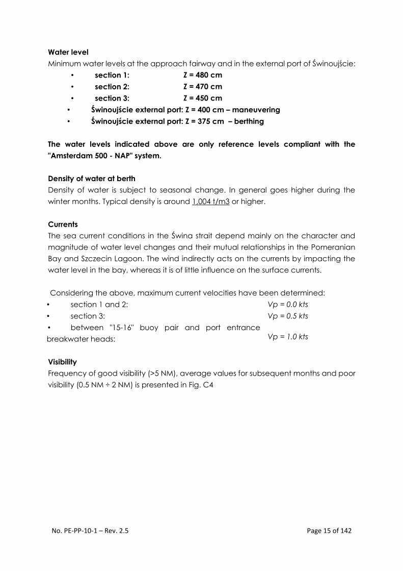
Water level
Minimum water levels at the approach fairway and in the external port of Świnoujście:
• section 1: Z = 480 cm
• section 2: Z = 470 cm
• section 3: Z = 450 cm
• Świnoujście external port: Z = 400 cm – maneuvering
• Świnoujście external port: Z = 375 cm – berthing
The water levels indicated above are only reference levels compliant with the
"Amsterdam 500 - NAP" system.
Density of water at berth
Density of water is subject to seasonal change. In general goes higher during the
winter months. Typical density is around 1,004 t/m3 or higher.
Currents
The sea current conditions in the Świna strait depend mainly on the character and
magnitude of water level changes and their mutual relationships in the Pomeranian
Bay and Szczecin Lagoon. The wind indirectly acts on the currents by impacting the
water level in the bay, whereas it is of little influence on the surface currents.
Considering the above, maximum current velocities have been determined:
• section 1 and 2: Vp = 0.0 kts
• section 3: Vp = 0.5 kts
• between "15-16" buoy pair and port entrance
breakwater heads:
Vp = 1.0 kts
Visibility
Frequency of good visibility (>5 NM), average values for subsequent months and poor
visibility (0.5 NM ÷ 2 NM) is presented in Fig. C4

No. PE-PP-10-1 – Rev. 2.5 Page 16 of 142
Fig. C4 Average frequencies of visibility of >5 NM and average frequencies of visibility
0.5 NM ÷ 2 NM (data for the period 1969 ÷ 1999)
Ice presence
Analyzing the ice conditions in the Pomeranian Bay, following may be adopted:
• Section 1: no ice presence;
• Section 2 and section 3 from KP 10.0: no ice presence;
• Section 3 between port entrance breakwater heads to KP 10.0:
− average number of days with ice presence: 10,
− maximum number of days with ice presence: 70,
− average ice cover thickness: 15 cm,
− maximum ice cover thickness: 35 cm,
− period of possible ice presence: from end of November to end of February.
• external port in Świnoujście:
− average number of days with ice presence: 40,
− maximum number of days with ice presence: 70,
− average ice cover thickness: 15 cm,
− maximum ice cover thickness: 35 cm,
− period of possible ice presence: from end of November to end of February.
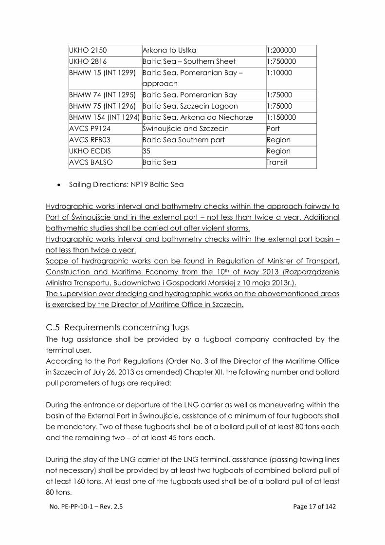
C.4 Charts and nautical publications:
Available publications Admiralty Paper Chart and Vector Chart as well as the
Hydrographic Office of the Polish Navy (BHMW) Charts:
Map number Title Scale /
comments
UKHO 2676 Szczecin and Świnoujście 1:10000
UKHO 2677 Szczecin Lagoon – Northern Part 1:35000
UKHO 2679 Pomeranian Bay 1:75000
No. PE-PP-10-1 – Rev. 2.5 Page 17 of 142
UKHO 2150 Arkona to Ustka 1:200000
UKHO 2816 Baltic Sea – Southern Sheet 1:750000
BHMW 15 (INT 1299) Baltic Sea. Pomeranian Bay –
approach
1:10000
BHMW 74 (INT 1295) Baltic Sea. Pomeranian Bay 1:75000
BHMW 75 (INT 1296) Baltic Sea. Szczecin Lagoon 1:75000
BHMW 154 (INT 1294) Baltic Sea. Arkona do Niechorze 1:150000
AVCS P9124 Świnoujście and Szczecin Port
AVCS RFB03 Baltic Sea Southern part Region
UKHO ECDIS 35 Region
AVCS BALSO Baltic Sea Transit
Sailing Directions: NP19 Baltic Sea
Hydrographic works interval and bathymetry checks within the approach fairway to
Port of Świnoujście and in the external port – not less than twice a year. Additional
bathymetric studies shall be carried out after violent storms.
Hydrographic works interval and bathymetry checks within the external port basin –
not less than twice a year.
Scope of hydrographic works can be found in Regulation of Minister of Transport,
Construction and Maritime Economy from the 10th of May 2013 (Rozporządzenie
Ministra Transportu, Budownictwa i Gospodarki Morskiej z 10 maja 2013r.).
The supervision over dredging and hydrographic works on the abovementioned areas
is exercised by the Director of Maritime Office in Szczecin.
C.5 Requirements concerning tugs
The tug assistance shall be provided by a tugboat company contracted by the
terminal user.
According to the Port Regulations (Order No. 3 of the Director of the Maritime Office
in Szczecin of July 26, 2013 as amended) Chapter XII, the following number and bollard
pull parameters of tugs are required:
During the entrance or departure of the LNG carrier as well as maneuvering within the
basin of the External Port in Świnoujście, assistance of a minimum of four tugboats shall
be mandatory. Two of these tugboats shall be of a bollard pull of at least 80 tons each
and the remaining two – of at least 45 tons each.
During the stay of the LNG carrier at the LNG terminal, assistance (passing towing lines
not necessary) shall be provided by at least two tugboats of combined bollard pull of
at least 160 tons. At least one of the tugboats used shall be of a bollard pull of at least
80 tons.

No. PE-PP-10-1 – Rev. 2.5 Page 18 of 142
The required composition of the tugboat group, apart from those listed above, shall
be supplemented with an additional tugboat of bollard pull of at least 45 tons which
shall constitute a back-up vessel ready for immediate deployment for the
maneuvering operation should any of the basic tugboats fail.
The tug assistance for the LNG carrier entering the External Port in Świnoujście shall be
as follows:
1) within the section of the approach fairway at a position located 1 NM north of
"1-2" buoy pair and during emergency stoppage within the emergency
maneuvering basin – one tugboat with bollard pull of at least 80 tons shall be
used to provide passive assistance as well as one tugboat with bollard pull of
at least 80 tons providing active assistance with connected stern tow;
2) within the section of the approach fairway between "13-14" buoy pair – two
tugboats with bollard pull of at least 80 tons each shall be used to provide
active assistance with connected stern and bow tow;
3) from "15-16" buoy pair onwards – four tugboats shall be used to provide
assistance as in point 2) above and the remaining tugboats assisting in the
manner ordered by the pilot in consultation with the LNG carrier Captain.
The tugboat assistance for the LNG carrier departing the External Port in Świnoujście
shall be as follows:
1) Two tugboats shall be of a bollard pull of at least 80 tons each and the
remaining two – of at least 45 tons each – as far as "15-16" buoy pair;
2) with two tugboats with combined bollard pull of at least 160 tons – as far as "9-
10" buoy pair;
3) with a single tugboat with bollard pull of at least 80 tons – as far as "5-6" buoy
pair on the approach fairway and during the emergency stoppage within the
emergency maneuvering basin;
4) in the manner executed according to the instructions of the pilot in consultation
with the LNG carrier captain.

No. PE-PP-10-1 – Rev. 2.5 Page 19 of 142
Fig. C.5 Tug assistance during entrance to the port

No. PE-PP-10-1 – Rev. 2.5 Page 20 of 142
Fig. C.6 Tug assistance during departure from the port
No. PE-PP-10-1 – Rev. 2.5 Page 21 of 142
C.6 Requirements concerning fire-fighting ship
According to Port Regulations (§ 182) LNG carriers are obliged to use fire-fighting ship
attendance. The fire-fighting ship must be suitable for assisting LNG carriers.
Fire ship must attend LNG carrier:
During her movement on the approach fairway from 13 – 14 buoy pair to
external port in Świnoujście.
During berthing and unberthing.
During the vessel stay at berth.
The fire ship attending moored LNG carrier must be ready for immediate action in the
vicinity of LNG carrier.
One of the tugs may assume the role of fire-fighting ship (reserve unit described in §188
point 3 of Port Regulations) if she is FiFi1class, has parameters described in § 180 point
1 and additionally manned with professional fire fighters from the rescue unit of the Port
Fire Service (“Portowa Służba Ratownicza).
The responsible for fire-fighting equipment, crew training and fire-fighting assistance is
hold by the fire unit commander on board the fire ship.
C.7 Requirements concerning the notification of arrival of the LNG
carrier at the terminal
The vessel captain shall be obliged to deliver the documentation of the vessel, crew
and cargo allowing for entrance to the Port in accordance with the requirements of
the Port Regulations and pursuant to the provisions set out in Section E.3 herein. It is
recommended to liaise with a shipping agent to determine the list of currently required
documents.
Part of the documents, such as Notification of Departure from the Port of Loading and
Notification of Arrival, can be found on the website of PLNG S.A. www.polskielng.pl
The information which must be provided in the above documents refer, among other,
to the port of loading, LNG quantity, its chemical composition, pressure in the cargo
tanks, etc. The specimens of the above documents constitute Appendices Nos. 6 and
7 of this instruction. Required and acceptable LNG spec. can be found in Terminal
Manual available on Operator’s website www.polskielng.pl and in the table below.

No. PE-PP-10-1 – Rev. 2.5 Page 22 of 142
Component
Acceptable LNG specification
range
C1 (%mol) 87 -95,4
C2 (%mol) 3,2 - 8,37
C3 (%mol) 0 - 3
iC4+nC4 (%mol) 0 - 1,2
nC5 (%mol) 0 - 0,23
N2 (%mol) 0,2 -1,4
In accordance with the Terminal Service Manual available on www.polskielng.pl
website, the Terminal User shall ensure that upon departure of the LNG Carrier from
the Port of Loading and no later than 24 hours of such a departure the Terminal
Operator is provided with the Notice of Departure along with all information pertaining
to the LNG Carrier which may be of relevance for the operations performed in the Port
of Unloading.
The most important information for the terminal operator is as follows:
1. Name and call sign of the vessels
2. Captain’s name
3. Arrival draught
4. Cargo volume to be unloaded
5. Last port of call
6. ISPS pre entry checklist
7. Crew list
8. ETA
9. Confirmation of compliance of temperatures and pressures in the cargo tanks
In practice, this comes down to filling in and forwarding the forms of Notice of
Departure from the Port of Loading and Notification of Arrival included respectively in
Appendix No. 6 and No. 7 herein.
Notice of Departure from the Load Port shall be submitted to the Terminal Operator
not later than 24 hours of departure from the Port of Loading.
Notification of Arrival shall be submitted not later than 7 days before the LNG Carrier’s
arrival at the Port of Świnoujście roadstead. An update of ETA time is required at this
stage if the change in the expected time of arrival exceeds 12 hours.
No. PE-PP-10-1 – Rev. 2.5 Page 23 of 142
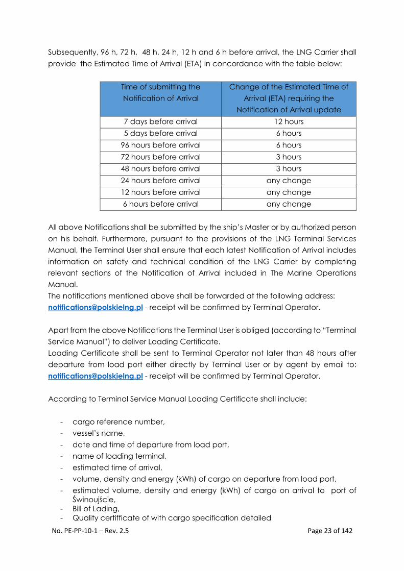
Subsequently, 96 h, 72 h, 48 h, 24 h, 12 h and 6 h before arrival, the LNG Carrier shall
provide the Estimated Time of Arrival (ETA) in concordance with the table below:
Time of submitting the
Notification of Arrival
Change of the Estimated Time of
Arrival (ETA) requiring the
Notification of Arrival update
7 days before arrival 12 hours
5 days before arrival 6 hours
96 hours before arrival 6 hours
72 hours before arrival 3 hours
48 hours before arrival 3 hours
24 hours before arrival any change
12 hours before arrival any change
6 hours before arrival any change
All above Notifications shall be submitted by the ship’s Master or by authorized person
on his behalf. Furthermore, pursuant to the provisions of the LNG Terminal Services
Manual, the Terminal User shall ensure that each latest Notification of Arrival includes
information on safety and technical condition of the LNG Carrier by completing
relevant sections of the Notification of Arrival included in The Marine Operations
Manual.
The notifications mentioned above shall be forwarded at the following address:
[email protected] - receipt will be confirmed by Terminal Operator.
Apart from the above Notifications the Terminal User is obliged (according to “Terminal
Service Manual”) to deliver Loading Certificate.
Loading Certificate shall be sent to Terminal Operator not later than 48 hours after
departure from load port either directly by Terminal User or by agent by email to:
[email protected] - receipt will be confirmed by Terminal Operator.
According to Terminal Service Manual Loading Certificate shall include:
- cargo reference number,
- vessel’s name,
- date and time of departure from load port,
- name of loading terminal,
- estimated time of arrival,
- volume, density and energy (kWh) of cargo on departure from load port,
- estimated volume, density and energy (kWh) of cargo on arrival to port of
Świnoujście,
- Bill of Lading,
- Quality certifficate of with cargo specification detailed

No. PE-PP-10-1 – Rev. 2.5 Page 24 of 142
- Certificate of Origin,
- Cargo Manifest.
For detailed information on commercial aspects of the vessel’s arrival, such as arrival
timeframe, unloading timeframe, principles governing the tendering of the Notice of
Readiness, activities preceding the unloading operation as well as estimation of the
volume of unloaded LNG please refer to complete contents of Chapter 7 in the
Terminal Service Manual () available on www.polskielng.pl
PLNG S.A, as the Operator of the LNG Terminal in Świnoujście is in no way liable, does
not participate or intermediate in the communications between the LNG Carrier and
port’s administration i.e. control services of port authority and VTS. In spite of this, in
order to ensure the completeness of the Marine Operations Manual, the requirements
and the manner of communication between the LNG Carrier and port administration
were described in Section E.3 herein, including the references to Chapter 3 of Port
Regulations and ALRS vol. VI.

No. PE-PP-10-1 – Rev. 2.5 Page 25 of 142
D. Terminal safety regulations and policy
Polskie LNG S.A. as the operator of the terminal is also, within the meaning of the Port
Regulations, the user of the berth and is responsible for ensuring safe berthing and
unloading of an LNG carrier at the terminal. The detailed scope of responsibility and
berth user roles in ensuring safe port operations are specified in the Port Regulations,
Port Facility Security Plan, Internal Emergency and Rescue Plan, this manual and other
documents.
D.1 Restricted access zone around the LNG carrier.
The operator of the LNG terminal in Świnoujście has established a restricted access
zone around the LNG carrier berthing at the terminal. It is defined in the Port Facility
Security Plan and corresponds with the hazard zone identified by quantitative risk
analysis for the marine part of the LNG Terminal. Radius of the restricted access zone
stretches 200 m from the manifold connection between the LNG Carrier and the
unloading arms of the plant. The entrance to the external port basin during the stay of
the LNG carrier at the berth shall be constantly monitored by the terminal personnel
and Polish Coastguard patrol unit – in accordance with the Port Facility Security Plan.
D.2 Consequences of breaching the terminal security rules
During the entire period of stay of the LNG carrier at the terminal, the entire ship crew
and visiting persons shall be obliged to fully adhere to the security rules of the LNG
Terminal specified herein, Terminal Internal Rescue and Operation Plan and Terminal
Emergency Response Plan. The Captain and crew of LNG carrier will be familiarized
with the key aspects related to safe stay of the ship at PLNG Terminal prior to
commence cargo operations Failure to comply with these regulations may result in
consequences including expulsion of personnel from the terminal.
Additionally, persistent breaching of the security policy rules may result in instigation of
the proceedings by the Marine LNG Terminal operator against the ship, including the
withholding of unloading operations and, in extreme cases, expulsion of the ship from
the terminal.
The terminal operator and users shall bear no financial responsibility for any activities
resulting from the repair of failures caused as a result of ship personnel's breach of the
terminal security rules.

No. PE-PP-10-1 – Rev. 2.5 Page 26 of 142
D.3 Reference to the health and safety and environmental protection
rules in force at the terminal
Environmental Protection
The oils and oil-contaminated water must not be discharged from the ship on the
waters of the Pomeranian Bay. During the stay of the LNG carrier at the berth, internal
fuel transfer operations shall be forbidden. Any spills must be immediately reported to
the terminal operator and to adequate services (Duty Officer of the Port Authority and
VTS).
Collection of oil-contaminated waste and garbage
Collection of oil-contaminated waste and garbage is possible at the LNG terminal only
from the off-shore side according to rules set out in item F11.
Information concerning the system of waste disposal in the Ports of Szczecin and
Świnoujście:
The system of waste collection from the ships is mandatory which means that all
facilities operating within the sea port in Szczecin and sea port in Świnoujście, as well
as ships using the berths located in both ports are obliged to comply therewith. The
above system does not apply only to the inland water vessels.
In accordance with the regulations of the Minister of Infrastructure of December 21,
2002 on management plans in ports for waste and cargo residues from ships. (Journal
of Laws No. 236, item 1989 of 2002). ZMPSiŚ S.A. developed the "Waste and ship cargo
residue management plan in the sea port of Szczecin" and "Waste and ship cargo
residue management plan in the sea port of Świnoujście". The plans have been
agreed with the port users and approved by the Zachodniopomorskie Province
Governor by virtue of a decision issued for the sea port management of Szczecin and
Świnoujście. The plans which constitute the basis for operation of the system for waste
collection from ships are available at the Environmental Protection and Health and
Safety Department of ZMPSiŚ S.A. and on ZMPSiŚ website: www.port.szczecin.pl.
Manifolds not used during unloading
The manifolds which are not used for unloading or BOG return must be blinded and
their valves (ESD, by-pass/cooldown and doubleshut) must be closed.
Cargo vapors
Inside the port, discharge of cargo vapors into the atmosphere is forbidden.

No. PE-PP-10-1 – Rev. 2.5 Page 27 of 142
Preventing environmental pollution
In accordance with the MARPOL convention and SECA Zones legislation (in force since
01/01/2010) all LNG carrier ships on their way to the terminal and at the terminal must
have used fuel with sulfur content below 1% vol. in the Baltic Sea.
Starting 01/01/2015, the maximum allowed sulfur content is decreased to 0.1 % vol.
Bunkering
In general, bunkering during the stay of the ship at the terminal shall be forbidden. It
shall be allowed only in exceptional cases, based on the rules specified in item F8.
Inerting purging and venting of the cargo tanks
Operations other than those stipulated in this manual shall be forbidden during the
stay of the LNG carrier at the berth.
D.4 Reference to safety regulations and checklists (ISGOTT 5th edition)
The entire personnel involved in the LNG loading operations must be familiarized with
the information contained in the following publications and industry standards:
Regulation No. 3 of the Director of the Maritime Office in Szczecin of 26/07/2013
"Port Regulations" (English version available on www.ums.gov.pl)
International Code For The Construction And Equipment Of Ships Carrying
Liquefied Gases In Bulk (IGC Code). Resolution MSC.30(61), Resolutions
MSC.32(63) and MSC.59(67)
The International Ship and Port Facility Security Code (ISPS Code)
OCIMF ISGOTT - International Safety Guide for Oil Tankers and Terminals – 5th
edition
SIGTTO - Liquefied Gas Handling Principles on Ships and in Terminals - 3rd edition
(April 2000)
SIGTTO - LNG Operations in Port Areas (September 2003)
SIGTTO - Guide to Contingency Planning for Marine Terminals Handling
Liquefied Gases in Bulk-2nd edition (2001)
SIGTTO Training of Terminal Staff involved in Loading and Discharging Gas
Carrier (1996)
SIGTTO Jetty Maintenance and Inspection Guide (2008)
SIGTTO Ship Vetting and its Application to LNG (2004)
Liquefied Gas Fire Hazard Management - First Edition (2004)
OCIMF Marine Terminal Management and Self-Assessment (MTMSA)
OCIMF Marine Terminal Particulars Questionnaire (MTPQ)
OCIMF Marine Terminal Operator Competence & Training (MTOCT)

No. PE-PP-10-1 – Rev. 2.5 Page 28 of 142
The Marine LNG Terminal of PLNG S.A. in Świnoujście applies all safety rules and
practices specified in the current issue of ISGOTT (5th edition). The checklist and safety
check-line shall be in compliance with the ISGOTT checklists.
Failure to comply with the rules and practices contained in ISGOTT shall result in
consequences described in chapter D.2.
D.5 Rules concerning the persons visiting the ship
The terminal shall ensure safe connection between the ship and the terminal. The
terminal shall ensure also adequate security measures against access of unauthorized
persons also within the area of the LNG terminal and jetty. It is expected that the ship
will ensure own security measures against access of unauthorized persons from the
ship sides in accordance with the ISPS code. The terminal normally operates at level 1
– in accordance with the ISPS code. Implementation of level 2 or 3 shall be
communicated to the ship in advance – during information exchange between the
ship and terminal.
The ship should maintain constant observation and report presence of any
unidentified vessels in the port basin and notify the terminal security service of this fact.
If a need arises, the terminal operator shall take actions to ensure safe stay and
unloading of an LNG carrier during its stay at the berth.
Based on the regulations of the International Ship and Port Facility Security Code (ISPS),
the area in which the Terminal is located is classified as a "Restricted access area"
which means that the vessels present at the terminal are required to comply with
security and safety regulations in accordance with the regulations of the
aforementioned Code.
Visiting of the ship by persons from outside is permitted only subject to the terminal shift
manager's or loading master’s consent. All visiting persons must be equipped, as a
minimum, with a hard hat, safety goggles, long trousers and upper body garment
covering their arms. Visiting persons must be accompanied at the terminal at all times
by an employee indicated by the shift manager or loading master. The ship crew list
and list of authorized / visiting persons should be delivered to the terminal security
personnel and be available at the gangway.
In accordance with the Port Regulations, the officers of the Port Authority are
authorized during their duty to enter the ships, yards, storage facilities and other port
facilities for inspection of compliance with port regulations.
The berth user (terminal operator) shall be obliged to provide the Port Authority officers
with access to ships, yards, storage facilities and other port facilities for inspection of

No. PE-PP-10-1 – Rev. 2.5 Page 29 of 142
compliance with port regulations. The access of the Port Authority Officers shall be at
all times possible from the side of the land. The access from the side of the water shall
be possible provided that there is no interference with loading operations carried out
at a given time.
Crew changes are possible, provided that all customs, border and administrative
requirements have been met and minimum PPE rules are adhered to.
Within the marine part of the terminal, it is strictly forbidden to use mobile phones,
pagers and other equipment not meeting the requirements of the ATEX directive in
the scope of spark resistance. Should the Port Authority officers fail to have UHF radios
with adequate certification, they shall be provided by the terminal operator.
D.6 Terminal drug and alcohol policy
LNG Terminal in Świnoujście has “zero tolerance” policy for drug and alcohol which
applies to all personnel working or visiting the terminal. This approach also apply to the
crewmembers coming back from shore leave.
E. Procedures of entry into the outer port in Świnoujście – PE-PP-
10-1-1
Source: SKBT

No. PE-PP-10-1 – Rev. 2.5 Page 30 of 142
E.1 General information concerning the commercial port in Świnoujście.
The parameters of the approach fairway to the external port in Świnoujście:
• Safe depths of all sections of the approach fairway are as follows:
− Anchorage No. 3 minimum depth = 15.8 m;
− all other sections of fairways minimum depth = 14.5 m.
• Safe widths of the approach fairway and system of navigational marks are as
follows:
− between 0.0 Nm (breakwater heads) and 14,5 Nm of fairway b = 200 m;
− between 14,5 Nm and 19,1 Nm of fairway b > 220 m;
− between 19,1 Nm and 26,9 Nm of fairway b = 220 m;
The terminal operates 24/7 throughout the entire year. The access to the terminal
depends on weather conditions. The final decision on entry to the port and approach
to the terminal shall always be made by the ship's captain and assisting pilots.
For LNG carriers arriving at the terminal in Świnoujście for the first time, entry shall be
permitted only during daytime.
The maximum allowed speed of the LNG carrier entering the port at respective
sections of the approach fairway and in the VTS zone within the Pomeranian Bay are
specified in table E1:
Item Fairway section Maximum
speed [kts]
1. between "N-1" buoy and "9-10" buoy pair 10
2. between "9-10" buoy pair and "15-16" buoy
pair 8
3. between "15-16" buoy pair and within the
external port basin 4
Table E1
The maximum allowed speed of an LNG carrier in ballast departing from the Port of
Świnoujście, in the area of the roadstead and on the approach fairway, after passing
the "15-16" buoy pair shall be 12 knots.
E.2 The approach fairway, available anchorages and rules of their use
by LNG carriers
For the LNG carriers arriving at the LNG Terminal in Świnoujście, the assigned route may
be divided into two basic sections:
No. PE-PP-10-1 – Rev. 2.5 Page 31 of 142
1. Western approach fairway up to "N-1" buoy crossing the territorial sea of
Germany east of Ruegen Island between "Arkona" buoy through "Sassnitz” and
"SWIN-N” buoy to "N-1” buoy (Lat = 54°17.0´N; Lon = 014°16.4´E). The minimum
depth of the basin through which this fairway crosses is 14.5 m.
2. Approach fairway to the Port of Świnoujście between "N-1" buoy to the external
port breakwater heads. It is a fairway dredged to the depth of 14.5 m. The
approach fairway comprises:
a. Northern part of the approach fairway between "N-1” buoy and "N-2” buoy
and, further, to "3-4” buoy pair (14,5 Nm of the fairway – from the breakwater
heads). Its minimum depth of 14.5 m and width of 220 m is ensured, in its
majority, by natural basin depths except for the section 14,8 Nm ÷ 16,7 Nm
located between "1-2” and "3-4” buoy pairs which is a dredged to 14,5 m
fairway (natural depths are in the range of 13.5 m).
b. The southern part of the approach fairway crossing the Pomeranian Bay
between "3-4” buoy pair (14,5 Nm of the fairway) and central breakwater
head in Świnoujście (0.0 Nm). It is a dredged fairway with minimum depth of
14.5 m and width of 200 m. In the section between "3-4” buoy pair and "7-8”
buoy pair this fairway crosses the basin with natural depths of 13.5 m ÷ 14.5
m, whereas in the section between "7-8” buoy pair and "9-10” buoy pair it
crosses a basin with natural depths of 13.0 m ÷ 13.5 m.
The diagram of the approach fairway to Świnoujście together with anchorages,
speeds allowed in particular sections of the fairway and under-keel clearance is shown
in Fig. E1. The map of the external port in Świnoujście is shown in Fig. E2. Depths of the
maneuvering basins, i.e. port entrance, turning basin and approach to the berth, are
14.5 m.

No. PE-PP-10-1 – Rev. 2.5 Page 32 of 142
Fig. E1 Diagram of the approach fairway to the outer port of Świnoujście
Source: SKBT

No. PE-PP-10-1 – Rev. 2.5 Page 33 of 142
Fig. E2 External port in Świnoujście
E.3 Communication with Maritime Administration
Pursuant to the LNG Terminal Services Manual, the Terminal User (the entity contracting
regasification service and supplying LNG) shall obtain all available information
concerning access to the port directly from the Maritime Administration (duty officer
of the Port Authority and VTS).
Detailed information concerning the communication with maritime administration is
provided in chapter II of Port Regulations (available on www.ums.gov.pl) and in ALRS
Vol. VI.
Communication with Maritime Administration shall be managed separately from the
commercial communication described in section C.6 of this document. Especially
“Notice of Arrival’ required by Maritime Administration and “Notification of Arrival”
required by Terminal Operator shall be treated as separate documents with different
purpose and content.
The ship's master or an authorized representative of the ship's master shall be obliged
to submit a preliminary notice of arrival at the port authority or VTS in areas in which
such system operates.

No. PE-PP-10-1 – Rev. 2.5 Page 34 of 142
The preliminary notice of arrival shall be submitted in advance as indicated below:
not later than 24 hours before the arrival of the ship at the port of
destination or before the arrival at the pilot ship boarding point,
if the ship voyage is shorter than 24 hours – immediately after the ship has
departed from the last port,
if the port of destination has not been known earlier – immediately after
the ship's captain obtains such information.
Together with the preliminary notice, the following information shall be provided:
contact details:
- Designated Person ISM;
- person providing detailed information on the cargo if the ship in
question transports hazardous or potentially contaminating
cargo;
details of the hazardous or potentially contaminating cargo in
accordance with the rules set out in Section 17 of the Port Regulations;
ship class according to INF Code, together with Principle VII/14.2 where
applicable;
estimated departure time (ETD) from the port;
information on total number of persons onboard the ship;
information on cargo harmfulness category for chemical agents
transported in bulk.
Together with the preliminary notice, the ships should provide information on the waste
present onboard the ship.
The ship performing regular voyages between the ports of the European Union
Member States may be released from the obligations set out in section 1 under
separate regulations.
Following documents should be appended to the preliminary notice:
Passenger List – IMO FAL FORM 6;
Crew's Effects Declaration – IMO FAL FORM 4;
Ship's Stores Declaration – IMO FAL FORM 3;
Crew List – IMO FAL FORM 5;
Cargo Declaration or Hazardous Goods form – IMO FAL FORM 2 or IMO
FAL FORM 7 respectively;
Maritime Declaration of Health.
The ship's captain or an authorized representative of the captain of a ship subject to
mandatory notification for performance of the extended Port State Control inspection
shall be obliged to notify the ship arrival at a port or anchorage of this port not later
than 72 hours in advance of the arrival or prior to departure from the previous port if
the voyage will take less than three days.

No. PE-PP-10-1 – Rev. 2.5 Page 35 of 142
The ship's captain or an authorized representative of the ship's captain shall, after
arrival, submit the following:
at the port authority or VTS in areas where this system is in operation, the
notice of arrival on IMO General Declaration - IMO FAL FORM 1;
at the port authority - maritime transport registry form the specimen and
application scope of which are specified in separate regulations.
The ship's captain or an authorized representative of the ship's captain shall, prior to
departure from the port, submit the following at the port authority or VTS in areas where
this system is in operation:
the departure notification on IMO General Declaration – IMO FAL FORM
1;
Passenger List – IMO FAL FORM 6;
Crew List – IMO FAL FORM 5;
Cargo Declaration or Hazardous Goods form – IMO FAL FORM 2 or IMO
FAL FORM 7 respectively;
Ship's Stores Declaration – IMO FAL FORM 3.
The ship's captain or an authorized representative of the ship's captain shall submit, to
the port authority, the maritime transport registry form the specimen and application
scope of which are specified in separate regulations:
not later than 1 business day from the departure of the ship from the port;
not later than 1 business day after conclusion of a given month – if the
form contains collective information for a given month.
The documents and information listed above shall be submitted in the components
PRE – ARRIVAL, PSC Notice, IMO FAL (for approval) respectively, of the PHICS system.
In the event of PHICS system failure, the documents and information listed above shall
be submitted to the port authority of VTS in areas where this system is in operation, on
the forms the specimens of which are defined in separate regulations, in writing, by e-
mail or by fax.
For the needs of vessel traffic and port operations, following rules shall be followed:
VTS area Świnoujście:
1) operational channel: 12 VHF, 70 VHF DSC code 002610800;
2) call sign: Świnoujście Traffic;
3) area: roadstead, Port of Świnoujście and Świnoujście – Szczecin fairway as far
as 2nd Gate ("Brama Torowa");
4) purpose: contact between VTS operator and moving vessels or vessels
intending to move;
5) VHF channel 12 shall only be used for communication between VTS and the
ship;
6) for the exchange of information between onshore entities and the VTS operator
concerning the traffic of vessels on the fairway and their mooring, telephone
communications should be used;

No. PE-PP-10-1 – Rev. 2.5 Page 36 of 142
7) the entrepreneurs may designate other call channels for their purposes within
the assigned frequency ranges;
8) arrangements between the ship and VTS requiring longer time shall be made
on VHF channel 18.
Port of Świnoujście area, for ship mooring and unberthing services;
1) operational channel: VHF 17;
2) area: commercial port areas including the production and ship repair yards:
3) purpose: maintaining communication between the pilot, tugboat, berth (dock)
administration, berth master and wharfman;
4) in the event of higher number of simultaneous mooring, unberthing and
docking operations, the communication between the ship and the tugboat or
other vessels involved in these operations, VHF channel 08 or 06 should be used
with observance of the rules specified in radio communications rules and with
application of following restrictions:
a) transmission power should be reduced to 1 W,
b) communication should be immediately ceased and moved to a different VHF
channel upon receiving information that using the VHF 06 channel interrupts
communication
in an on-going rescue operation carried out with the use of aircraft.
E.4 Communication between the ship and terminal operator
In accordance with Chapter 7 of the LNG Terminal Services Manual:
The terminal user shall ensure that irrespective of the notification of Carrier’s arrival
required under mandatory provisions of law, the captain of the carrier or his agent
notifies the Terminal Operator using a relevant form available at the webpage of the
Terminal Operator on the following: identification information of a Carrier, Port of
Destination, on the time of departure from the port of loading and the estimated time
of arrival at the roadstead (hereinafter referred to as “Notification of Arrival”).
Such a Notification of Arrival shall be submitted not later than 7 days prior to the arrival
of the Carrier to the Świnoujście PortRoadstead. The Terminal User shall also submit a
Notification of Arrival ninety-six (96), seventy-two (72), forty-eight (48), twenty-four (24),
twelve (12) and six (6) hours before the arrival of the Carrier to the Roadstead.
Detailed information concerning the communications between the LNG Carrier and
the Terminal Operator is provided in Section C.6 of MOM and Chapter 7 of the LNG
Terminal Services Manual.
No. PE-PP-10-1 – Rev. 2.5 Page 37 of 142
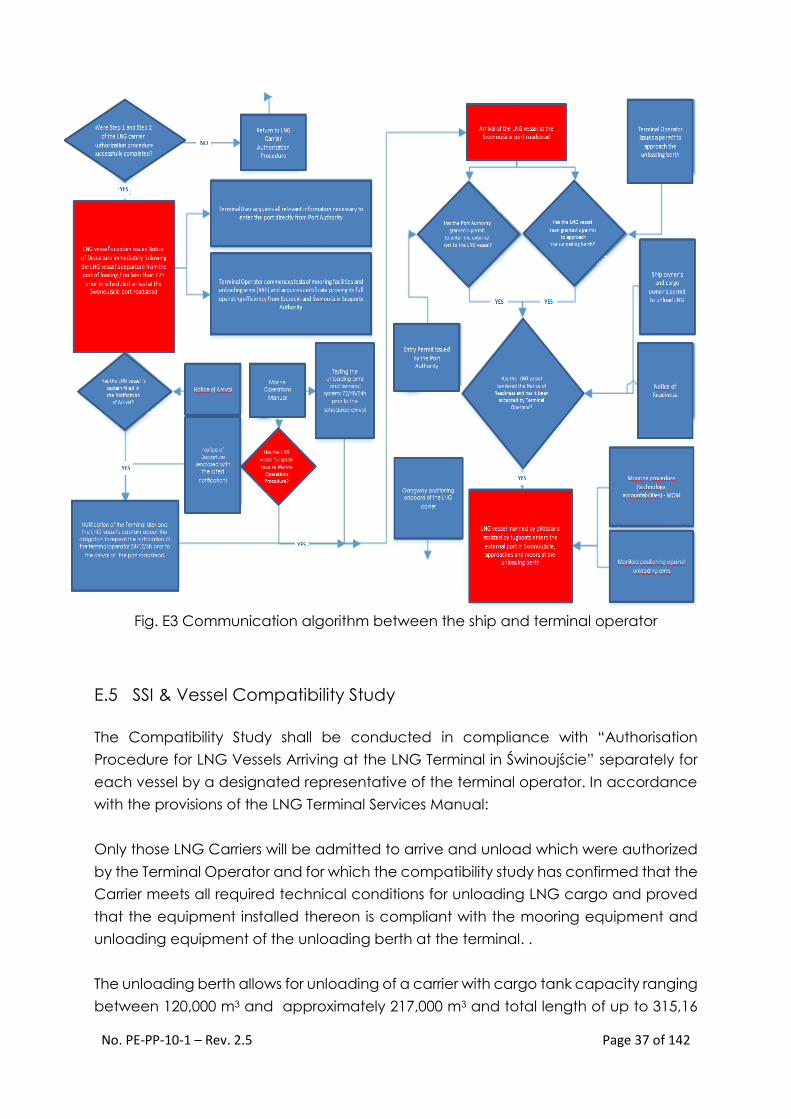
Fig. E3 Communication algorithm between the ship and terminal operator
E.5 SSI & Vessel Compatibility Study
The Compatibility Study shall be conducted in compliance with “Authorisation
Procedure for LNG Vessels Arriving at the LNG Terminal in Świnoujście” separately for
each vessel by a designated representative of the terminal operator. In accordance
with the provisions of the LNG Terminal Services Manual:
Only those LNG Carriers will be admitted to arrive and unload which were authorized
by the Terminal Operator and for which the compatibility study has confirmed that the
Carrier meets all required technical conditions for unloading LNG cargo and proved
that the equipment installed thereon is compliant with the mooring equipment and
unloading equipment of the unloading berth at the terminal. .
The unloading berth allows for unloading of a carrier with cargo tank capacity ranging
between 120,000 m3 and approximately 217,000 m3 and total length of up to 315,16

No. PE-PP-10-1 – Rev. 2.5 Page 38 of 142
m, width of up to 50 m and maximum draft of 12.5 m fresh water. In the event of positive
verification in the authorization procedure, unloading of LNG from carriers of
parameters different from those specified above shall be possible.
In accordance with the design of the terminal, the minimum cargo capacity of a LNG
carrier shall be 50,000 m3.
Throughout the validity period of the authorization, the Operator shall retain the right
to verify the authorization of any carrier, primarily by means of inspections, and to
render the maintenance of authorization dependent upon demanded adjustments,
particularly in the scope of metering instruments (CTMS). In justified cases, the operator
shall be entitled to refuse the consent for unloading from a carrier or stay at the
unloading berth or shall be entitled to cancel the authorization.
The approval process of a carrier arriving at the LNG terminal in Świnoujście shall follow
the algorithm below which constitutes a part of the "LNG Carrier Approval Procedure
for Carriers Arriving at the LNG Terminal in Świnoujście” – PE-PP-10-1-6 which
constitutes a separate manual available on the operator's website www.polskielng.pl.
The complete list of documents required for accomplishing the Carrier authorization
procedure is contained in the "LNG Carrier Approval Procedure for Carriers Arriving at
the LNG Terminal in Świnoujście” as well as in Chapter 7 of the LNG Terminal Services
Manual.

No. PE-PP-10-1 – Rev. 2.5 Page 39 of 142
Fig. E4 Authorization algorithm – source: Approval Procedure of a carrier arriving at
the LNG terminal in Świnoujście.
No. PE-PP-10-1 – Rev. 2.5 Page 40 of 142
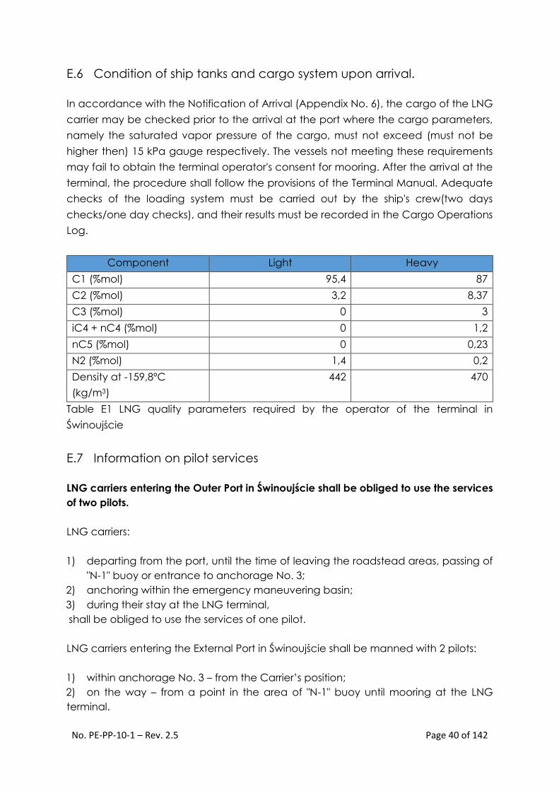
E.6 Condition of ship tanks and cargo system upon arrival.
In accordance with the Notification of Arrival (Appendix No. 6), the cargo of the LNG
carrier may be checked prior to the arrival at the port where the cargo parameters,
namely the saturated vapor pressure of the cargo, must not exceed (must not be
higher then) 15 kPa gauge respectively. The vessels not meeting these requirements
may fail to obtain the terminal operator's consent for mooring. After the arrival at the
terminal, the procedure shall follow the provisions of the Terminal Manual. Adequate
checks of the loading system must be carried out by the ship's crew(two days
checks/one day checks), and their results must be recorded in the Cargo Operations
Log.
Component Light Heavy
C1 (%mol) 95,4 87
C2 (%mol) 3,2 8,37
C3 (%mol) 0 3
iC4 + nC4 (%mol) 0 1,2
nC5 (%mol) 0 0,23
N2 (%mol) 1,4 0,2
Density at -159,8ºC
(kg/m3)
442 470
Table E1 LNG quality parameters required by the operator of the terminal in
Świnoujście
E.7 Information on pilot services
LNG carriers entering the Outer Port in Świnoujście shall be obliged to use the services
of two pilots.
LNG carriers:
1) departing from the port, until the time of leaving the roadstead areas, passing of
"N-1" buoy or entrance to anchorage No. 3;
2) anchoring within the emergency maneuvering basin;
3) during their stay at the LNG terminal,
shall be obliged to use the services of one pilot.
LNG carriers entering the External Port in Świnoujście shall be manned with 2 pilots:
1) within anchorage No. 3 – from the Carrier’s position;
2) on the way – from a point in the area of "N-1" buoy until mooring at the LNG
terminal.

No. PE-PP-10-1 – Rev. 2.5 Page 41 of 142
Ordering pilot services shall be the responsibility of the ship's captain or his authorized
representative at the pilot station:
1) for ships entering the port – at least 4 hours before planned time of pilot boarding
the ship;
2) for ships departing from the port – at least 2 hours before planned time of ship
departure;
2. The order for pilot services should contain:
1) ship name, call sign, flag;
2) ship gross tonnage (GT);
3) ship length overall (LOA);
4) maximum draft in fresh water;
5) estimated arrival time to the pilot boarding ground (ETA);
6) details of the tugboats intended for ship handling;
7) any information concerning the place and manner of ship mooring.
Orders for pilot services shall be placed at the dispatchers in Szczecin or Świnoujście.
By phone: Szczecin: +48 91 432 56 56, +48 604 200 093
Świnoujście: +48 91 321 34 31
By e-mail: [email protected]
Over the Internet: http://www.szczecinpilot.pl/zamawianie
Świnoujście Pilot Station Dispatch Office
Contact Person: Dispatcher
Call sign: Świnoujście Pilot
VHF: channel 68
Phone (24h): +48 91 321 34 31
Fax: +48 91 321 34 31
e-mail: [email protected]
Detailed information on the regulations governing pilot services may be
found in ALRS Vol. VI and chapters VI and XII of the Port Regulations.

No. PE-PP-10-1 – Rev. 2.5 Page 42 of 142
Requirements concerning pilot equipment in accordance with the IMPA:
Fig. E5. Pilot Poster

No. PE-PP-10-1 – Rev. 2.5 Page 43 of 142
E.8 "Master/Pilot Exchange” checklist
Captain/Pilot checklist compliant with the maritime administration requirements
constitutes an appendix to the port regulations.
No. PE-PP-10-1 – Rev. 2.5 Page 44 of 142
E.9 Conclusions of the FMBS
A total number of 14 valid simulation runs were carried out, including emergency
maneuvers, and the total net simulation time was approximately 22 hours. Before
starting, a number of test runs were done to facilitate adaptation to the maneuvering
conditions.
The following conclusions can be drawn from the evaluation and simulation runs taking
into account the level of difficulty in executing the maneuvers, the tug requirements
and the simulated emergency maneuvers:
Normal maneuvers:
• In 10 m/s of mean wind speed, (gusting up to 12.5 m/s), regardless of direction,
current up to 1.0 knots, and waves of 1.2 m significant height, the fairway is
accessible for Q- Flex LNG carriers. The wind is predominant safety factor.
• Winds of more than 10 m/s knots can slightly hinder maneuvers when wind
direction is coincident with outgoing current (wind from W and current veering
to E) close to harbour breakwaters' heads, increasing the drift angle to
approximately 5°. The critical area of the channel where the bridge team
needs to be more vigilant is between 15-16 buoys and turning basin inside outer
harbour, because of channel direction change, shallow water in front of central
breakwater and necessity to support by PPU. There is also strict necessity to keep
speed below 4kts in the 200m wide channel between breakwaters in order to
effectively cope with bank effect. The stopping distance from the entrance to
outer harbour to the turning basin is sufficient to stop the vessel within turning
basin limits with the maneuver strategy used in the study. No more than half
astern was used during stopping maneuver.
• The tug formation comprises two 80t ASD tugs connected by 50m to l00m
towing lines at the stern and the bow, and up to three pushing tugs (two active
and one in close standby), each of 45 t, which can be connected at the sunken
bits starboard/port bow, sunken bit starboard/port quarter and starboard/port
stern according to pilots' wishes. The side where tugs are located is port in
normal conditions as the vessel is berthing starboard side after rotation in turning
basin. This is sufficient to turn the ship around and move it safely to the terminal
in the conditions studied.
• During departure maneuvers the effect of the wind increases compared to that
of the arrival due to the ship's smaller draft and the greater area exposed to the
wind. Anyway the 80t tugs can cope that effectively. Departure maneuvers are
direct. The tugs separate the ship from the quay and she navigates with their
assistance towards the fairway to leave the port. The same tug formation,
consisting of four ASD tugs and one additional in standby, is sufficient to
No. PE-PP-10-1 – Rev. 2.5 Page 45 of 142
separate the ship from the terminal and keep her under control until passing 15-
16 buoys where all the tugs except stern one separate.
Emergency maneuvers:
• All conducted emergency maneuvers have been properly solved using the
proposed tug formation, rudder, engine and anchors. The combination of the
available means of maneuver were enough to keep the vessel under control
and within the fairway and inside outer harbour 14.5m isobath limits.
• Tugs failure during turning maneuver of 80t ASD tug has been assessed (towing
line parted or tug broke down in Scenario No. 3 24/02). The power of the
remaining tugs was sufficient to control and turn the ship and move her to the
terminal in a safe fashion. Anyway, the power required from tugs was
considerably high during prolonged periods of time (they used up to Ix80tx75%
and 3x45tx75% simultaneously for prolonged periods of time).
• Anyway, this case corresponds to an emergency situation, therefore this
conclusion cannot be extrapolated to other normal situations.
Tug Requirements:
• The minimum tug formation recommended for Q-Flex vessels at Świnoujście Port
is 5 ASD tugs (3 with a bollard pull of 45 tonnes each and two extra with 80
tonnes). During normal maneuvers, 4 tugs have worked simultaneously at 50%
of the time for prolonged periods of time, therefore all 5 ASD tugs are required.
• This tug formation results enough for navigation, turning and berthing stages in
the conditions studied (mean wind speed of 10 m/s, 1.0 kts current and 1.2 m
significant wave height).
• As already commented, the tug fleet considered was capable of solving all
emergency maneuvers considered, tugs were capable to stop the vessel,
control the vessel and turn the vessel in a safe and controlled way.
Navigable Areas:
• The fairway for the entry at the port is wide and suitable enough for the access
of the Q-Flex to the port under the analyzed conditions, even though it has to
cope with a certain drift angle which increases the area occupied by the vessel
at the fairway. There is strict necessity to use Pilot Portable Unit (PPU) to support
navigation especially in the area between 15-16 buoys to the berth where
physical ATONs are not sufficient.
• The approach channel between breakwaters has width of 200m. The turning
basin is an oval shaped (l000m x 600m). The minimum distance to the limits of
the 14.5m isobaths inside-breakwaters channel during the simulation was 20m.
The minimum distance to the limits of the 14.5m isobath inside turning basin
during the simulation was 63m.

No. PE-PP-10-1 – Rev. 2.5 Page 46 of 142
• Turning area is sufficient to allow the safe and controlled turning of the Q-Flex
under the analyzed conditions.
Vertical Dimensions (UKC):
• Taking into account the current limits for the access of LNG carriers at
Świnoujście Port (under-keel clearance of not less than 2.0 m is maintained from
pair of buoys '9-10' and within maneuvering areas, while taking into
consideration water level forecast), the access to the port with Q-Flex fully
loaded (T=12.5 m) shows no interferences with the depth of the fairway, and
therefore, it is considered safe.
Aids to Navigation:
The available Aids to Navigation (AtoN) throughout the Świnoujście approach fairway
are as follows:
• 1 leading line,
• 2 sector lights at breakwaters heads,
• 2 IALA pillar mid-channel safety water buoys,
• 14 IALA pillar lateral buoys,
• 2 beacons (11-12),
• 8 special pillar yellow buoys marking anchorage areas.
Ali this available AtoNs are enough to ensure safe maneuvers except in the area
between 15- 16 buoys to the berth where PPU assistance is necessary.
Operational Limits:
• The maneuvers performed for the assessment of the access of the Q-Flex to
Świnoujście Port considered the worst case scenarios within the LNG Terminal
limitations for the access of LNG carriers.
• Mean wind speed not more than 12.5m/s in any direction (gusting up to 15m/s);
• Significant wave height not more than 1,5m;
• Current speed not more than 0.5kt (up to 1 .0kt locally) in any direction.
These conditions are adequate for the safe access of the Q-Flex towards Świnoujście
LNG Terminal
Recommendations:
Pilots considered that in the fairway the most critical wind direction are E and
W. They agreed strong wind affects tug assistance when the vessel reduces
speed at the port entrance and while berthing at speed - 0kts.
The necessity to keep speed <4kts in the channel between breakwaters in order
to effectively cope with bank effect was reiterated. Monitoring of the ship
position close to the fairway axis via visuals and electronic pilot navigation
system (PPU) was emphasized by all parties.
No. PE-PP-10-1 – Rev. 2.5 Page 47 of 142
It was agreed that initial three (3) entries of vessel and first departure will be
performed during the day light hours.
The final tug formation of 2x90t, 2x45t, lx55t is to be confirmed by harbour
authorities. All training scenarios have been prepared and performed with
2x80t, 3x45t BP tugs.
The tug masters confirm their ability to render passive assistance at a speed of
lOkts for the channel transit.
Further training focused in the knowledge of the Pilots / Captains and
Tugmasters to:
Determine the most effective positions of the available tugs and tug types,
taking account of when, where and how tug assistance is required during
passage towards the berth, at the berth or when departing.
The capabilities and limitations and efficient use of the propulsion and steering
control systems of tug types while assisting, and how to respond to propulsion
and steering control system failures.
The safe maneuvering of tug when passing and releasing the tow lines.
The most effective positions for pull and push tugs when required.
Effective communication between pilot and tugmaster and correct exchange
of information between pilot and tugmaster, and also tugmaster and his crew
regarding tug placement, intended maneuvers, towline use, etc.
The usage of PPU particularly in emergency situations was recommended.
F. Berth approach, mooring and berthing procedures – PE-PP-10-
1-2
F.1 Operational limits of the terminal (permissible carrier parameters)
The LNG Terminal in Świnoujście may receive ship with following maximum parameters:
Cargo capacity: from 120,000 to approximately 217,000 m3
Overall length up to 315,16 m
Breadth up to 50 m
Fresh water draft – 12.5 m
Maximum draft during unloading – 13.2 m (including static under-keel
clearance equal to 10% of maximum draft)
Maximum approach transverse speed – 0,05 m/s
Maximum angle of approach – 20
Berth heading - 358°
No. PE-PP-10-1 – Rev. 2.5 Page 48 of 142
After conducting compatibility study with a positive result, the terminal operator may
allow mooring of LNG carriers with minimum cargo capacity smaller than the
described above.
F.2 Maximum allowed hydrometeorological conditions during
entrance/departure from the port
VTS may allow an LNG carrier to enter the port, provided that:
wind speed does not exceed 10 m/s,
wave height does not exceed 1.2 m,
visibility is not worse than 1 Nm,
the current speed in the maneuvering basin between the port breakwater
heads and "15 -16” buoy pair does not exceed 0.5 knot (considered equivalent
to speed of 1.5 knot indicated by the meter located at the Świnoujście -
Szczecin fairway, at the height of GPK (Border Control Point) berth),
the water level ensures maintenance of the under-keel clearance not smaller
than 2.3 m on the approach fairway to the Port of Świnoujście to "9-10" buoy
pair, with consideration of forecast tendencies of water level changes,
the terminal panel operator reports the readiness for arrival of the carrier on VHF
channel 12 ,
the tugboat company providing services for the carrier reports the readiness,
composition of the vessel group and tugboat operability declaration on VHF
channel 12,
the weather forecast for the time of the carrier's port entry maneuver does not
stipulate rapid deterioration of weather conditions;
The LNG carrier captain or the pilot on captain's behalf reports to the VTS the passing
of "5-6" buoy pair on the access fairway to the Port of Świnoujście to obtain the consent
for continuation of the entry to the port. The VTS shall grant such consent, provided
that:
a) wind speed does not exceed 12.5 m/s,
b) wave height does not exceed 1.5 m,
c) the water level ensures maintenance of the under-keel clearance not smaller
than 2.0 m from "9-10" buoy pair and in ship maneuvering basins, with
consideration of forecast tendencies of water level changes,
VTS may allow an LNG carrier to depart from the port, provided that:
a) wind speed does not exceed 10 m/s,
b) wave height does not exceed 1.5 m,
c) visibility is not worse than 1 Nm,
d) the current speed in the maneuvering basin between the port breakwater
heads and "15 -16” buoy pair does not exceed 0.5 knot (considered equivalent
to speed of 1.5 knot indicated by the meter located at the Świnoujście -
Szczecin fairway, at the height of GPK (Border Control Point) berth),

No. PE-PP-10-1 – Rev. 2.5 Page 49 of 142
e) the terminal panel operator reports the readiness for unberthing of the carrier
on VHF channel 12 ,
f) the tugboat company providing services for the carrier reports the readiness,
composition of the vessel group and tugboat operability declaration on VHF
channel 12,
g) the weather forecast for the time of the carrier's port departure maneuver does
not stipulate rapid deterioration of weather conditions;
F.3 Port Regulations requirements for mooring assistance
Below mentioned requirements are set in Port Regulations as minimum and described
for information only. Terminal Operator requirements are more strict and have been
described on section F.4.
Berthing and berthing regulations
All ships of length overall of 50 m and more shall use the assistance of port linesmen.
The number of port linesmen servicing a ship depends on the length overall of a ship.
For ships of length overall exceed 200:
Berthing – minimum of 6; unberthing – minimum of 5.
Linesmen shall wear personal protection equipment, including life jackets, and work in
line with occupational safety and health regulations.
During berthing or unberthing, linesmen are managed by a berth user equipped with
means of communication with the ship. The user indicates a place of berthing for a
ship.
Each linesman shall be trained as regards service provided, based on a training
program recommended by the IMO, confirmed by a certificate.
At berths designated for transhipment of dangerous or polluting goods, mooring
operations, occupational safety and health and training requirements as regards work
provided shall be described in the Berth Safe Operation Instruction.
During berthing or unberthing of a ship a motorboat shall be used if mooring dolphins
are not linked with the berth by catwalks or when it is not possible to receive a mooring
line from the ship.
Detailed information concerning mooring and berthing regulations may be found in
chapter VIII of the Port Regulations.

No. PE-PP-10-1 – Rev. 2.5 Page 50 of 142
F.4 Terminal Operator requirements for mooring assistance and berth
equipment
In accordance with the requirements of the operator of the LNG terminal in
Świnoujście, the linesmen team must comprise at least 12 persons (including the crews
onboard mooring boats, at least 3 persons each). Two mooring boats must be used
for mooring of an LNG carrier which shall be adjusted for safe transport of two mooring
ropes simultaneously.
Apart from training and certificates required by Port Regulations, the linesmen must
have completed special training in service mooring infrastructure of the LNG terminal
in Świnoujście confirmed by an appropriate certificate issued by Terminal Operator.
The diagram of the LNG unloading berth in the external port in Świnoujście is shown in
Fig. F1. This diagram has been developed on the basis of the technical design of the
LNG unloading berth. The unloading berth is equipped with:
4 type Super Cone Fender berth fenders manufactured by Trelleborg Marine
Systems with a 3.5 m x 4.7 m fender plate (allowed mooring impact energy
1,500 kNm);
10 dual mooring hooks equipped with a remote mooring hook release system
as well as the mooring rope tension monitoring system with a possibility of
monitoring from the ship;
4 un-loading arms located on the DN400 platform (3 un-loading arms for LNG
and 1 for vapor return);
gangway tower and mobile gangway with the ship movement tracking system;
2 remotely-controlled fire monitors.
Fig. F1 Diagram of the berth at the LNG terminal in Świnoujście

No. PE-PP-10-1 – Rev. 2.5 Page 51 of 142
LNG Carrier mooring procedure at the terminal in Świnoujście is as follows:
Parallel approach to the berth to a distance of approx. 1 ship width – lateral
speed control by pushing tugboats.
Springs are lowered to approx. 1 m above water level and taken up to mooring
boats – two ropes simultaneously. Spring might also be send one by one. Final
decision is to be made by the captain and pilots.
The mooring boats tow the forward and aft springs to adequate dolphins – the
ship's crew gradually slackens the ropes to allow the mooring boats to
maneuver freely.
The linesmen onshore pass the messenger rope to the mooring boats which is
subsequently attached to both springs after which they are hoisted onto the
mooring dolphins with capstans and attached in adequate sequence
(inboard/outboard) to quick-release hooks. Mooring boats withdraw to a safe
distance.
After correct attachment of springs to the hooks, disconnection of messenger
ropes and withdrawal of linesmen to a safe distance, one of the linesmen gives
a signal to the officers on maneuvering stations that rope heaving may
commence.
The springs are heaved up and the ship is simultaneously pushed towards the
berth. At this stage, particular attention should be paid to transverse approach
speed shown on the PNDS system display and on the pagers held by pilots. In
the final phase of ship approach to the fenders, by skillfully pulling the springs
one should ensure that these ropes do not become trapped between the ship
side and the fenders.
After the parallel part of the ship hull becomes resting against the fender
devices, its positioning against unloading arms shall commence. The Gas
Engineer, maintaining radio communication with the vessel’s captain, and the
Loading Master together with the Pilots and directly with the Gas Engineer,
acting in a coordinated manner to position the BOG return manifold against
the unloading arms and issuing relevant maneuvering orders. The ship shall be
positioned according to the spotting line – alignment of symmetry line of the
vapor manifold with the BOG return arm.
When the manifold of the LNG carrier is correctly aligned with respect to the
unloading arms, the "in position" communication is issued which shall be
confirmed by the ship's captain. Next, the captain orders "make fast forward
and aft springs".
After fastening of the springs and uncoupling of the spring winches,
subsequently the breasts lines, head line and stern line shall be handed in the
manner described above.

No. PE-PP-10-1 – Rev. 2.5 Page 52 of 142
After handing and making fast of all mooring ropes, the towing lines shall be
cast (in some cases, in order to hand the head and stern lines, it is necessary to
cast the towing line on the bow and stern before the former are handed).
After completion of the mooring operation, the crew shall fasten the fire wires
from the side of the water, 1.5 m above water level (in accordance with
ISGOTT). If the vessel if fitted with sunken bitts of an appropriate strength, which
in case of emergency, allow the tugs to safely connect towing lines then there
is no need to use fire wires. Abovementioned approach become a standard
practice recommended by OCIMF. Decision should be made upon completion
of ship shore compatibility study described in LNG Carrier Approval Procedure
(PE-PP-10-1-6).
Upon unberthing, the mooring ropes are slackened and released from hooks in
reverse sequence with regard to that during mooring. The linesmen and ship's
crew maintain particular care when casting the mooring lines. The officer at the
maneuvering station must not order any given line or rope to be heaved up
without clear indication from a linesman that it may be done.
When casting springs, it is practicable to wait with full slackening until the ropes
are fully beyond the contour of the fender devices. This will prevent potential
contact between springs and fenders which may pose a hazard to the
linesmen.
Handing the ropes to the mooring lines shall be performed with good maritime
practices and with particular care for their crews' safety.
The same applies to fastening and casting the tow line – good maritime
practices should be observed and all personnel shall realize large forces that
act on the tow line and particular care should be maintained.
Fig. F2 Positioning of the ship at the berth

No. PE-PP-10-1 – Rev. 2.5 Page 53 of 142
Fig. F3 Mooring diagram for the a class Q-Flex LNG carrier
F.5 Berth equipment
The berth shall be equipped with the following devices:
1. 4 loading arms located on the DN400 platform (3 loading arms for LNG and 1
for vapor return), operating range as in appendix J9;
2. Gangway tower with a mobile gangway equipped with a ship movement
tracking system – operating range as in appendix J11;
3. 2 remotely-controlled fire monitors;
4. System for indication of approach speed (in cm/s) with mobile displays for pilots
and a display board at the berth;
5. Mooring rope tension monitoring system (mobile for the CCR and permanent in
the main control room and jetty control room);
F.6 International Shore Connection
The international coupling is located at the bottom of unloading platform and it is
equipped with a shut-off valve. The terminal fire water network is always pressurized.
F.7 Taking provisions and stores by the ship
Taking provisions and stores by the ship is possible only from the side of the water and
requires the terminal operator's consent at all times. The LNG carrier captain should
notify the terminal operator (through an agent) on the intention to obtain provisions
and/or stores during the stay at the terminal.
Loading of stores and spare parts to the ship must not collide with loading operations.
Prior to such operations, it is necessary to arrange this during the pre-unloading
meeting. When the unloading arms are connected, it is not allowed for any supply
vessels to attach to the carriers side.
The ship's captain, through an agent, shall be obliged to notify the duty officer of the
Port Authority and VTS on each planned provision and store taking operation by the
No. PE-PP-10-1 – Rev. 2.5 Page 54 of 142
ship, with indication of the involved supply vessel as well as the commencement and
completion time of such operation.
F.8 Bunkering
In general, bunkering during the stay of the ship at the terminal shall not be allowed.
In exceptional cases, when the ship obtains the consent of the terminal operator to
remain for a longer time at the berth and incurs all related costs, bunkering shall be
allowed only from the sea side and after disconnection of unloading arms. The ship's
master, through an agent, shall be obliged to notify the Duty Officer of the Port
Authority and VTS on each planned bunkering operation by the ship, with indication
of the involved bunker vessel as well as the commencement and completion time of
such operation.
F.9 Repairs
Any repairs that may affect the ship capacity of independent maneuvers are
forbidden during the stay of the ship at the terminal. Any exemptions must be agreed
with the Terminal Loading Master.
F.10 Managing ballast water
The LNG carrier entering Baltic Sea must replace ballast water in accordance with
MARPOL and HELCOM conventions and must have a Ballast Water Management Plan
implemented that shall comply with the resolution of IMO - MEPC.127(53) and shall
record the ballast water replacement in the Ballast Water Record Book.
The LNG carriers entering the LNG terminal in Świnoujście, due to the amount of cargo
they transport, carry only limited amount of ballast water or no ballast water at all. If
for any reasons, the ballast tanks are partially filled, it is not allowed to discharge ballast
water that has not been exchanged. The ship ballasting procedures during unloading
shall take the above principle into account.
F.11 Wastewater and waste disposal rules
The wastewater and waste handing over is allowed only from the side of the water
and requires the terminal operator's consent at all times.
The above operations shall not be allowed during unloading. The ship's captain shall
communicate the intention to hand over any waste (including wastewater) in
advance. It is necessary to fill in adequate document (though an agent) which
constitute appendices to the Waste and ship cargo residue management plan of
ZMPSiŚ (Szczecin and Świnoujście Sea Port Authority). The ship's captain, through an
agent, shall be obliged to notify the duty officer of the Port Authority and VTS on each
planned wastewater and waste handing operation by the ship, with indication of the

No. PE-PP-10-1 – Rev. 2.5 Page 55 of 142
involved vessel as well as the commencement and completion time of such
operation.
Necessary documents and forms are available on the website of ZMPSiŚ
http://www.port.szczecin.pl
F.12 Shore leave
Crew disembarkment shall be possible after all customs, border and administrative
requirements have been fulfilled and subject to observance of the ISPS code rules and
terminal security regulations. A member of the crew intending to disembark (shore
leave) must hold a photocopy of the passport containing a photograph and, as a
minimum, a hard hat, safety glasses, long trousers and upper body garment covering
their arms.
All personnel must comply with terminal “zero tolerance” drug & alcohol policy.
F.13 Preparation of the berth for the LNG carrier in winter conditions Ensuring readiness of the berth for mooring of an LNG carrier in winter conditions shall
be the responsibility of the berth owner – ZMPSiŚ (Szczecin and Świnoujście Sea Port
Authority). The terminal shift manager or loading master or his authorized deputy, after
obtaining the information on berth preparation – snow removal, ice removal of
mooring rope handling paths, circulation platforms, crushing of ice in the area of the
berth and maneuvering basin – shall check the preparation of the berth.
Ice breaking and winter maintenance of the approach fairway lays fully within
Maritime Administration and Seaport Management responsibility. There are two ice
breaking tugs available in Port of Świnoujście.

No. PE-PP-10-1 – Rev. 2.5 Page 56 of 142
G. Cargo operations – PE-PP-10-1-3
G.1 General information
The chapter below describes the operating procedures related to LNG unloading. The
maximum unloading rates that can be received by the terminal is 12,000 m3/hour with
connected three unloading arms and BOG return arm. The maximum operating
pressure during LNG unloading is 4.5 bar, while the maximum pressure in the BOG return
line is 16.5 kPa (165 mBar) which correspond to “high pressure” alarm setting of PIC-12
controller.
The unloading arms, mooring infrastructure (quick-release hooks, capstans) together
with the piloting, navigation and docking system and the gangway tower will be
tested at least 48 hours (test completion) before the expected arrival of the LNG
carrier. The piloting, navigation and docking system shall be started-up 3 hours before
the mooring. 2 hours before mooring the nitrogen flow in the loading arm venting
system shall be increased from 0.1-0.2 m3/h to 0.4-1.0 m3/h. After conducting the tests
of the mooring system together with the PNDS system, obtaining the confirmation of
their operability and verification of berth preparation for ship arrival in winter conditions
(item F12), the terminal operator, i.e. the berth user within the meaning of the Port
Regulations, represented by the shift manager or loading master, shall report readiness
to receive the ship to the Duty Officer of the Port Authority and the VTS.
Table G1. Design and operating parameters of the unloading arms
Systems tested by the terminal operator prior to the planned arrival of the LNG carrier:
Gangway tower with the gangway of maximum reach of 22,5 m (above Mean
Sea Level) and a shore crane with SWL = 2 tons and maximum outreach of 15
m.
Process tag LA-1011-A/B LA-1011-C LA-1012
Product handled LNG LNG/BOG BOG
Pressure
Operating 4.5 bar 4.5/0.165 bar 0.165 bar
Design 18.9 bar/
Full vacuum
18.9 bar/
Full vacuum
18.9 bar/
Full vacuum
Temperature Operating
-163.7 to -
159.2 °C
-163.7 to -120 °C -131.1 to -120 °C
Design -170/85°C -170/85°C -170/85°C
Max. flow rate
4,000 m3/h
(LNG)
4,000 m3/h
(LNG)
8,000 m3/h
(BOG)
12,000 m3/h
(BOG)

No. PE-PP-10-1 – Rev. 2.5 Page 57 of 142
Jetty Spillage System and Jetty Impounding Basin – located beyond the north-
eastern corner of unloading platform on the separate installation.
Fire protection system.
Fire and gas detection system.
Emergency Shut Down/Process Shut Down/Unit Shut Down and Local Shut
Down systems (activated by the terminal).
UHF and VHF radio communications system.
PAGA Intercom internal communication system and CCTV system.
Ship to Shore Link System – electrical, fiber optic and pneumatic connections.
Quick-release hook system (hand, local and remote release testing).
Piloting, Navigation and Docking System (PNDS) together with environmental
monitoring system.
Terminal lighting.
Cargo sampling system, laboratory and online chromatograph (field operator
or laboratory technician task).
G.2 Supervision over the operation and division of responsibilities
For the needs of this chapter, following definitions of positions and responsibilities
during the LNG carrier unloading operation have been adopted:
"Loading Master" shall be the persons designated by the terminal operator who
shall be responsible for the management of LNG unloading operation. It is an
employee of the terminal operator.
"Ship Duty Officer" shall be a Chief Officer of the LNG carrier or a person thereby
appointed as the contact person competent in all operations related to LNG
unloading. Ship Duty Officer shall be the Loading Master's counterpart onboard
the ship.
The LNG carrier Captain shall be the person with overall responsibility for ship
safety both during port entry and mooring. The captain shall also be overall
responsible for ship safety during the stay at the terminal.
"LNG carrier Pilot" is a person holding necessary marine qualifications,
knowledge and experience in the scope of safe maneuvering of LNG carriers
and additionally the scope of qualification requirements for marine pilots –
specialist training on the FMBS simulator for the Świnoujście external port
approach for a given class of LNG carriers evidenced by a relevant certificate.
He acts as an advisor to the ship Captain and acting in full cooperation with
the Captain, he ensures safe entry to the port, approach to the berth and
mooring. The pilot's responsibility is regulated by law.
"Tugboat Captain" is a person responsible for safety of the tugboat assistance
operations. He works under the supervision of the pilot and LNG carrier's
Captain.

No. PE-PP-10-1 – Rev. 2.5 Page 58 of 142
"Mooring Master" is a direct superior or linesmen who coordinates their work. He
takes orders directly from the Loading Master.
"Panel Operator (DCS Operator)" is a person supervising the unloading
operation from the jetty control room and main control room. He is an
employee of the terminal operator and works under supervision of a Shift
Manager and a Loading Master (during unloading operations).
"Field Operator (Operator)" is a terminal employee performing activities
necessary for controlling the process at the field. He works under the supervision
of the Duty Panel operator and Shift Manager, and in the marine part of the
terminal – also supervised by an Loading Master.
Shift Manager is the superior of panel operators and field operators who
supervises unloading and storage operations as well as LNG regasification
process from the main control room. He is an employee of the terminal's
operator and works under the supervision of the Terminal Operations
Superintendent and, for the time of LNG unloading operation, also under the
supervision of the Loading Master especially in case of any marine
emergencies.
The term "Terminal" shall mean a Loading Master or persons within his scope of
responsibility or working under his supervision, the term "LNG Carrier" shall mean
a Chief Officer / Duty Officer of a carrier or persons in the scope of his
responsibility and the term "Pilot" shall mean the pilot of the LNG Carrier.
All activities described in this section shall be carried out in close coordination
between the Terminal and the Ship.
When the LNG carrier is moored at the berth, the responsibility for the safety of
unloading operation shall be on the part of both the ship and the terminal. On the part
of the ship, the supervision over the unloading operation shall be performed by the
Chief Officer and, on the part of the terminal, the Loading Master and Shift Manager.
When the ship is positioned at to the berth, her manifold and terminal unloading
platform must be constantly manned and monitored by trained personnel. On the part
of the ship, this is the cargo watch, while on the part of the terminal, this shall be the
operators of unloading arms.
Duties of the panel operator and operators after completion of a shift include the
following activities:
Making sure that the ship/terminal connection ensures safe course of the
unloading operation;
Checking the condition of unloading arms;
Checking the condition of unloading pipelines (according to a separate
manual);
Filling in and update of the loading operations log (temperatures / pressures)
during cooling of the loading arms;

No. PE-PP-10-1 – Rev. 2.5 Page 59 of 142
Making sure that no LNG leaks or excessive BOG emission presence occur.
Checking the safety of the LNG unloading operation at the berths and in the area of
the ship's manifold as well as monitoring of the forces acting on the ship's mooring
system shall be carried out from the jetty control room with the use of the camera
system and the Smart Hook system which is a part of the Integrated Maritime
Navigation Safety System. Maximum and minimum load on particular mooring lines
are determined by individual Optimoor analyses and they are communicated during
the pre-discharge meeting..
Monitoring of hydrometeorological conditions by the terminal shall be ensured by the
environmental monitoring system(WXT520, Aandreaa DCS-4100, WTLS) included in the
scope of the integrated monitoring system. The shift panel operator or a person
indicated by the shift manager is obliged to monitor from the main control room and
jetty control room the parameters such as: wind speed and direction, atmospheric
precipitation and pressure, temperature, air humidity, current speed and direction,
tide level and wave action parameters – all the above information is provided by the
systems installed at the terminal. The shift panel operatorat the jetty control room or
the persons indicated by the shift manager shall immediately inform the shift manager
and loading master and directly the ship duty officer on occurrence or a risk of
occurrence of boundary conditions requiring the LNG unloading operation to be
ceased. The ship duty officer shall immediately inform the captain and the pilot
onboard the LNG carrier of such fact while the pilot and/or captain shall notify the
Duty Officer of the Port Authority and the VTS. The ship duty officer shall also be obliged
to monitor the wind parameters from the Cargo Control Room. In the scope of
activities to be taken in the event of boundary conditions by the shift panel operator
or a persons indicated by the shift manager, the deciding person shall be the Loading
Master acting in consultation with the ship's captain.
The duties of the unloading arms operators include passing of the earthing cable to
the ship which shall subsequently be attached to the dedicated point on the ships hull
by a crew member. Next the ESD system cable (electrical, optical or pneumatic) is
passed to the ship and it shall be connected to a correct socket on the LNG carrier by
a member of her crew. During the connection, the ESD system switch shall be in "off"
position. It shall be switched to "on" position after making sure that the cable has been
correctly attached to the ship's socket.
At this stage, a member of the LNG carrier shall switch on the water curtain.
G.3 Gangway positioning
When the ship is moored safely and all above mentioned ship-terminal connections
have been correctly established, a qualified employee of the terminal (panel
operator) shall lower the gangway onboard of the LNG carrier. The members of the

No. PE-PP-10-1 – Rev. 2.5 Page 60 of 142
ship's cargo watch and terminal's shift make sure together that the gangway and the
gangway tower is correctly illuminated during night time.
In practice, items G.2 and G.3 may be performed simultaneously, however one should
remember about the necessity to hand the earthing cable prior to deployment of the
gangway.
Shore gangway is located 24,40 m forward of the spotting line. For starboard side
alongside the gangway will be landed forward of the manifold.
Fig. G.1. Gangway position in relation to ship’s side
Schematics and parameters of the gangway tower and the gangway also the range
and SWL of the crane are given in appendix 11 to this manual.
G.4 LNG unloading procedure and pre-discharge meeting
Before the LNG unloading operation. A pre-discharge meeting is held onboard the
ship. The meeting objectives are as follows:
Confirmation of the unloading schedule and pumping rates.
Exchange of any required information concerning the system and equipment
of the Ship and the Terminal .
Arrangement of all cargo data and requirements concerning the unloading.
Arrangement of the D1011-PIC-12 BOG vapor return controller set point.
Discussion on purging methodology.
Discussion on CTMS requirements.
Carrying out of a safety inspection aboard (by the Loading Master or a person
indicated by him and Carrier’s Duty Officer or a person indicated by him)
confirming that all safety requirements have been met, before the
commencement of unloading operation.

No. PE-PP-10-1 – Rev. 2.5 Page 61 of 142
Filling of a "Ship/shore safety checklist" or an equivalent document.
The meeting shall be attended, on the part of the ship, by the ship captain
(recommended) and chief officer (mandatory), while on the part of the terminal, the
Loading Master. The suggested meeting agenda and, at the same time, the pre-
discharge meeting checklist constitutes an appendix to this manual.
A set comprising a radio telephone Motorola GP830 EX set to UHF channel 1 together
with a charger and a spare battery shall be delivered to the Cargo Control Room of
the ship by the terminal loading master and shall be used for emergency
communications between the Ship and the Terminal should the hot line system or
regular telephone systems fail.
During the pre-discharge meeting, the ship's captain shall sign the information letters
of the terminal operator concerning the safety and environmental protection as well
as ISPS statement (in accordance with International Ship and Port Facility Security
Code).
In turn, the senior officer together with the terminal loading master shall fill in the SSSCL
according to their best knowledge, experience and filling instructions contained
therein. The SSSCL constitutes an appendix No. 2 to this manual. Periodical checks of
all items which, in accordance with code "R", require such activity, shall be carried out
at least every 4 hours.
Wind speed boundary conditions (operability conditions) for the LNG unloading
operation are as follows:
Unloading stops > 15 m/s
Disconnection of unloading arms > 17,5 m/s
*Consider Unberting > 20 m/s
Operation resumes < 15 m/s
Other cases resulting in the necessity to stop the unloading operation:
Fire or spill at the LNG carrier.
Fire or spill at the terminal.
Uncontrolled movement of the ship with regard to the berth.
Exceeding of the operating range of the unloading arms – activation of ESD 1.
Activation of ESD 2.
*If the environmental conditions persist, Vessel Master and loading Master to discuss
with the O/B Pilot on the need to depart the berth and shift to the contingency
anchorage (turning basin) with the supporting tugs in attendance.
In each case, the stopping of the unloading operation, disconnection of arms,
emergency unberthing and resumption of operations shall be decided by the Loading
Master in consultation with the ship's Captain.

No. PE-PP-10-1 – Rev. 2.5 Page 62 of 142
Notice of Readiness
In accordance with the Terminal Manual, the Notice of Readiness may be tendered
after obtaining the consent of entry of the ship to the port from the maritime
administration (VTS) at the earliest. NOR is usually accepted by the Terminal Operator
at “all fast”.
G.5 Connection of unloading and BOG return arms
After filling in of the SSSCL (or during this activity, after necessary arrangements for
respective checklist items) the authorized representative of the terminal operator
(Loading Master) in consultation with the Carrier’s senior officer shall issue a consent to
connect the unloading arms. Connection shall be carried out after the arm operators
have made sure that no contamination is present inside the manifold and that the ship
crew has correctly installed adequate unloading filters (60 mesh strainers). The arm
operator shall position it adequately in front of a respective manifold. The arm shall be
stopped at a distance of several dozen centimeters from the manifold, after which the
blind flange shall be removed. After this operation, the unloading arm shall be
connected to the ship manifold with a quick connect / disconnect coupler (QC/DC).
This activity shall be repeated for subsequent unloading arms and the BOG return arm.
The gaskets are supplied by the terminal. In principle, the first arm to be connected is
the BOG return arm. BOG return arm is also the last arm to be disconnected.
G.6 Leak test and pressure test
In order to ensure optimal coordination, this procedure must be performed for all arms
one after another and reported to the Ship. The proposed sequence of the operation
is intended to optimize nitrogen consumption with the leak test being performed in first
line and followed by N2 purging. The nitrogen pressure in the unloading arms shall be
increased to approx. 5.0 Bar and in the BOG return arms to approx. 2.0 Bar to carry out
the connection tightness test - in practice, it is performed by the ship's Gas Engineer
together with the arm operator using a special liquid. The pressure is subsequently
released by relief valves located on the unloading platform of the terminal and on the
LNG carrier manifold. The purging activity shall be repeated until O2 concentration of
less than 1% by volume is achieved which must be measured and confirmed by the
ship's Gas Engineer with a relevant detector.
G.7 Preliminary CTMS measurement.
The preliminary CTMS measurement should be performed before the warm ESD test
and before unloading arms’ cooldown. During the commencement of the CTMS
measurement, all valves of the manifold must be closed. The measurement shall be
carried out in the presence of a Chief Officer, authorized terminal representative and
an independent surveyor – appointed under an agreement between the ship
owner/operator, terminal operator and terminal user. Correct measurement shall be

No. PE-PP-10-1 – Rev. 2.5 Page 63 of 142
performed with the use of adequate software of the main CTMS system installed on
the LNG carrier. It is required to maintain the back-up system operational as well at
that time. The CTMS calibration system certificate and the tank gauging tables should
always be available onboard. The CTMS system printout shall be signed by a chief
officer, authorized terminal representative (Loading Master) and independent cargo
surveyor.
If the ship utilizes BOG to supply the engine, it shall meet the requirements of Annex VI
of the MARPOL convention and shall be able to switch from combustion of gas to
combustion of conventional fuel. The amount of gas combusted between the
preliminary and final CTMS measurement must be calculated and given together with
the amount of cargo that has been unloaded. The procedure for measurement of gas
combusted in the engine shall be agreed between all parties.
The re-liquefaction plant (if installed) may be kept in operation during initial and final
CTMS, this must be taken into account in cargo calculations.
For further information please refer Terminal Service Manual. Terminal Service Manual
and current edition of GIIGNL LNG Custody Transfer Handbook.
G.8 BOG handling system configuration
Free flow of cargo vapor BOG shall take place between the ship and the terminal. It
results from the difference of pressure which is created as a result of LNG level changes
in the ship's and terminal's LNG storage tanks. The valves on the BOG return line from
the terminal may be opened only after the preliminary CTMS measurement has been
completed, but this depends on the BOG pressure in ship tanks which must be
recorded during the pre-discharge meeting. The BOG vapor return valve on the ship
may be opened after the terminal control room operator has been informed and after
the operator confirms that the BOG return valve at the terminal has been opened.
In case of unlikely situation when the pressure in ship’s cargo tanks is exceeded and
the vessel has no other mean to control it and simultaneously the terminal is not in
position to take BOG ashore yet it possible to obtain terminal permission for venting
BOG to atmosphere (as a rule it is forbidden and can only be allowed in exceptional
circumstances)
G.9 "Warm ESD” test
The objective of the test confirming the unloading is to verify whether the unloading
arm ESD (Emergency Shut-Down) level 1 function executed by the terminal ESD system
is executed correctly in terms of closing of the ESD system valves onshore.
The UZ-ESD2A (unloading arm ESD level 1 function for excessive projection of the
unloading arm) and UZ-ESD2B (activation of the unloading arm ESD level 1 function +
disconnection of the PERC for the second level of excessive projection of the
unloading arm) functions which are executed by the unloading arm PLC controller
shall NOT be tested during the pre-discharge tests.

No. PE-PP-10-1 – Rev. 2.5 Page 64 of 142
Prior to commencement of the unloading arm cool-down process, two warm ESD
(primary and secondary link) tests shall be conducted. One shall involve the activation
of the system from the side of the ship and the other shall involve activation from the
side of the terminal. During the test, ship/shore and shore/ship communications must
be checked. In order to mitigate the effects of uncontrolled pressure rise in the
unloading arms, during the tests a confirmation should be obtained that the ship's ESD
valves close before the terminal's ESD valves and that emergency stop of the
unloading pumps and closing of valves on the transfer lines takes place in an
adequate sequence. In any case, the closing time of the ESD valves on the ship and
at the terminal must not exceed 30 seconds.
G.10 Unloading arm and line cool-down
The scope of cool-down procedure is intended to obtain target cool-down level of
three liquid unloading arms and to obtain even cool-down of the flanges to prevent
leaks (the BOG return arm does not require cooling).
The estimated cool-down times are ca. 60 minutes. The objective is to obtain cool-
down of three unloading arms LA-1011-A/B/C, down to the temperature of -130 °C or
lower at maximum cool-down rate of between 8 and 10 °C per minute.
The unloading arm cool-down process must be effected in close cooperation
between the LNG carrier's senior officer and the terminal shift manager and Loading
Master. After confirmation that the valves on the ship and terminal unloading lines
have been correctly aligned and after mutual confirmation of readiness for cool-down
of the arms, following activities shall be performed:
After a signal from the terminal, the ship shall start the pumps;
The terminal loading master, acting in consultation with the arm operator and
ship's Gas Engineer shall control the LNG flow with adequate valves with the
progress of unloading arm cool-down process;
When the temperature inside the unloading arms reaches at least -130 0C, the
cool-down process is considered completed. Arms cooldown is carried out
according to Operating Manual – Unloading System.
G.11 "Cold ESD” test
The cold ESD test is performed at least once every 3 months in cooperation with the
ship. The procedure is similar to that of the warm ESD test, except for the fact that it is
performed after completion of unloading arm cool-down.
Valve closing check in cold conditions is normally performed before commencement
of unloading operation.
G.12 Unloading commencement and control
The design unloading rate equals 12,000 m3/h with ship manifold pressure of ca. 4.5
bar. If the pressure in ship manifold is lower, the unloading rate may be smaller than
12,000 m3/h. 4.5 bar manifold pressure shall not be exceeded.

No. PE-PP-10-1 – Rev. 2.5 Page 65 of 142
If the unloading rate exceeds 12,000 m3/h, the terminal compressors capacity may be
too low with regard to the generated amount of BOG and the excess gas may be sent
to the vent. Hence, it is not recommended to exceed the design unloading rate.
After completion of the unloading arms cool-down and ship's and terminal's
confirmation of readiness for LNG unloading, the unloading pumps shall be started. In
practice, it is performed in the following steps:
The terminal confirms that all valves on the LNG unloading line are open and
that it is of correct temperature;
The ship opens all valves on LNG cargo lines and closes the cool-down valves
connecting the spray lines with LNG lines at the manifold;
Subsequent pumps are started every 5-7 minutes with adequate notification
of the terminal in advance and terminal loading master consent;
The Chief Officer of the LNG carrier shall inform the terminal on achievement of
the unloading rates agreed during the pre-discharge meeting which must be
each time confirmed by the Terminal shift manager / Loading Master and
recorded in the cargo operations log.
G.13 Cargo sampling
An authorized employee of the terminal shall commence sampling of the LNG in
accordance with an applicable process manual, after the ship has confirmed that it
achieved fixed and stable unloading rate.
G.14 Unloading completion
Upon completion of the unloading operation, the chief officer should gradually
reduce the unloading rate, stopping the ship’s cargo pumps one after another. The
unloading must not be stopped abruptly, as this may result in a temporary pressure rise
/ hammering in the unloading system piping.
As the unloading progresses, the ship shall notify the terminal on the expected time of
completion and, in particular, on the unloading rate ramp down. The unloading
pumps are stopped by the ship in a relevant sequence and at specific time internals.
The information on stopping of each pump must be transferred to the terminal and,
after stopping of the last pump, the unloading completion takes place and its official
time must be agreed with the terminal. In the final phase of LNG unloading, particular
attention shall be paid to adequate BOG pressure control.
G.15 Drainage and nitrogen purge of unloading arms
The liquid unloading arms shall be fully emptied prior to disconnection from the LNG
carrier manifold flange.
The internal side of the unloading arms (i.e. onshore side) shall be emptied to the jetty
drain drum D-1011.The residual LNG on the external side of the unloading arms (i.e. on
the ship side) shall be removed with the use nitrogen for ship tanks. The nitrogen shall
be supplied to the unloading arms by the nitrogen purge lines located on the top of

No. PE-PP-10-1 – Rev. 2.5 Page 66 of 142
respective unloading arms and equipped with relevant shut-off valves. Unloading
arms shall be drained in concordance with SIGTTO guidelines set out in „LNG Transfer
Arms and Manifold Draining Purging and Disconnection Procedure” and as described
in Operating Manual – Unloading System.
After completion of unloading, the LNG remaining in the unloading arms shall be
drained in the following sequence:
Drainage of the internal parts of the unloading arms to the jetty drain drum ;
Fig. G1 – Unloading arms’ drainage by the terminal
Drainage of the contents of external part of the unloading arms to the ship
cargo system with the nitrogen supplied from the terminal;
Fig. G2 – Unloading arms’ drainage by the Carrier

No. PE-PP-10-1 – Rev. 2.5 Page 67 of 142
The unloading arms operator shall confirm that the unloading arms are liquid
free by opening the drainage valve on the purge line;
All arms are subsequently purged with nitrogen until the LNG has fully
evaporated and the ice collected on the arms during unloading has melted.
Upon disconnection of unloading arms, the content of methane shall not
exceed 2% of capacity. Which has to be confirmed with a gas meter suitable
to measure methane content in nitrogen,
WARNING: THE UNLOADING ARMS SHALL NOT BE SPRAYED WITH WATER TO SPEED UP
ICE MELTING
G.16 Final CTMS measurement and post-discharge meeting.
Prior to the final CTMS measurement, one should make sure that all ESD and double
shut-off valves on the manifold are closed. After this has been confirmed in the
presence of the chief officer, authorized representative of the terminal (Loading
Master) and an independent cargo surveyor, the final CTMS measurement shall take
place, printout shall be made and CTMS report signed.
After completion of unloading, the so-called post-discharge meeting shall take place.
The objectives of this meeting are as follows:
obtaining final agreement in the scope of cargo transfer control;
evaluation of the entire unloading operation;
suggestion of practically reasonable or feasible improvements for future
unloading operations;
documentation of safety areas, incorrect communication, uncertainty or other
problems and preparation of plans of further actions to address these issues;
execution of document implementation procedures (i.e. minutes of meetings,
checklists, etc.).
vessel final approval for further calls.
The post-discharge meeting may be carried out simultaneously with the following
activities:
disconnection of unloading arms;
switching off the water curtain;
disconnection of the ship from the ship-to-shore communication system.
The post-discharge meeting shall typically take place in the ship's Conference Room.
It has to be attended by at least the Loading Master and Chief Officer.
G.17 Disconnection of unloading and BOG return arms
After deicing of the unloading arms which may take up to several hours depending
on ambient temperature, the unloading arm operators and the ship's Gas Engineer
shall make sure that the concentration of methane is below 2% by volume and,
subsequently, they disconnect the unloading arms one by one and install the blind
flanges. After this activity, a short nitrogen purge shall be carried out to remove oxygen
No. PE-PP-10-1 – Rev. 2.5 Page 68 of 142
that has entered the unloading arms after disconnection. After this activity, the arms
are retracted to the terminal and locked in the resting position.
G.18 Post-discharge documentation
After receiving the result of the final CTMS measurement system and checking of the
atmospheric pressure. The calculation of the total unloaded LNG amount shall take
place in accordance with the methodology described in the Terminal Services
Manual. The documents needed at this stage have been presented in the algorithm
of the Marine Operational Manual constituting the Appendix to this Manual.
H. Emergency procedures – PE-PP-10-1-4
H.1 Source regulations and industry guidelines
Act on Maritime Safety of September 18, 2011.
Act on Protection of Marine Traffic and Sea Ports of October 4, 2008.
Act – Environmental Protection Law of April 27, 2001.
Ordinance of the Minister of Economy of October 10, 2013 on types and
quantities of hazardous substances the presence of which on the plant decides
on qualifying the plant as an increased risk plant or a plant with the high risk of
occurrence of serious industrial failures;
Ordinance of the Minister of Transportation, Construction and Maritime
Economy of June 22, 2012 on detailed organization of the Marine Search and
Rescue Service.
Regulation No. 3 of the Director of the Maritime Office in Szczecin of July 26,
2013 as amended: Port Regulations
Regulation No. 1 of the Director of the Maritime Office in Szczecin on fire safety
within sea ports and harbors of January 20, 1974 (as amended)
International Code for Construction and Equipment of Ships Carrying Liquefied
Gases in Bulk – ICG 1993
European Resuscitation Council guidelines – ERC 2010
Medical First Aid Guide For Use In Accidents Involving Dangerous Goods
(MFAG) - 2004 Edition
International Safety Guide for Oil Tankers and Terminals – ISGOTT 5th edition 2006
SIGTTO – Guide to Contingency Planning for Marine Terminals Handling
Liquefied Gases in Bulk – 2nd edition (2001)
OCIMF – Guide to Contingency Planning for the Gas Carrier Alongside and
Within Port Limits – 2nd edition (1999)
H.2 Introduction
In accordance with the provisions of Polish and international law, each marine
terminal should operate the approved and implemented emergency procedures.
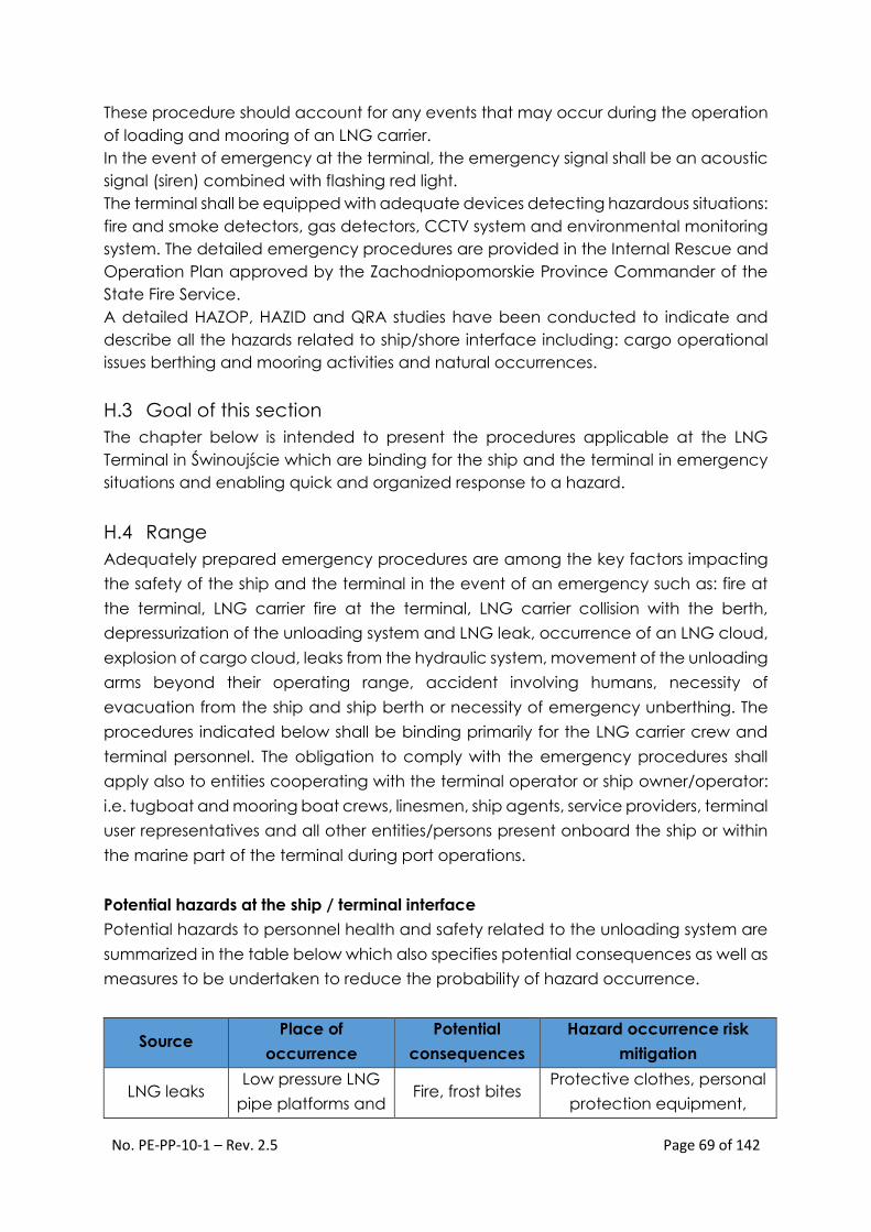
No. PE-PP-10-1 – Rev. 2.5 Page 69 of 142
These procedure should account for any events that may occur during the operation
of loading and mooring of an LNG carrier.
In the event of emergency at the terminal, the emergency signal shall be an acoustic
signal (siren) combined with flashing red light.
The terminal shall be equipped with adequate devices detecting hazardous situations:
fire and smoke detectors, gas detectors, CCTV system and environmental monitoring
system. The detailed emergency procedures are provided in the Internal Rescue and
Operation Plan approved by the Zachodniopomorskie Province Commander of the
State Fire Service.
A detailed HAZOP, HAZID and QRA studies have been conducted to indicate and
describe all the hazards related to ship/shore interface including: cargo operational
issues berthing and mooring activities and natural occurrences.
H.3 Goal of this section
The chapter below is intended to present the procedures applicable at the LNG
Terminal in Świnoujście which are binding for the ship and the terminal in emergency
situations and enabling quick and organized response to a hazard.
H.4 Range
Adequately prepared emergency procedures are among the key factors impacting
the safety of the ship and the terminal in the event of an emergency such as: fire at
the terminal, LNG carrier fire at the terminal, LNG carrier collision with the berth,
depressurization of the unloading system and LNG leak, occurrence of an LNG cloud,
explosion of cargo cloud, leaks from the hydraulic system, movement of the unloading
arms beyond their operating range, accident involving humans, necessity of
evacuation from the ship and ship berth or necessity of emergency unberthing. The
procedures indicated below shall be binding primarily for the LNG carrier crew and
terminal personnel. The obligation to comply with the emergency procedures shall
apply also to entities cooperating with the terminal operator or ship owner/operator:
i.e. tugboat and mooring boat crews, linesmen, ship agents, service providers, terminal
user representatives and all other entities/persons present onboard the ship or within
the marine part of the terminal during port operations.
Potential hazards at the ship / terminal interface
Potential hazards to personnel health and safety related to the unloading system are
summarized in the table below which also specifies potential consequences as well as
measures to be undertaken to reduce the probability of hazard occurrence.
Source Place of
occurrence
Potential
consequences
Hazard occurrence risk
mitigation
LNG leaks Low pressure LNG
pipe platforms and Fire, frost bites
Protective clothes, personal
protection equipment,

No. PE-PP-10-1 – Rev. 2.5 Page 70 of 142
Source Place of
occurrence
Potential
consequences
Hazard occurrence risk
mitigation
delivery pipelines,
recondenser area
trainings, gas detectors,
operating manuals and
work station procedures.
Natural gas
leaks
BOG return
header, jetty drain
drum and BOG
return arm
Fire, explosion
Protective clothes, personal
protection equipment,
trainings, gas detectors,
operating manuals and
work station procedures.
Electric
Current
Electrical networks,
electrical panels of
unloading arms
and auxiliary
systems
Electric shock,
serious body
injuries, burns,
death
Restricted access to
electrical equipment,
description of electrical
devices, warning marks,
work station procedures,
working and protective
clothing, personal
protective equipment,
equipment for penetration
protection.
Rotating
equipment
Unloading arms
hydraulic pumps
Serious body
injuries, death
Personal protection
equipment, trainings,
operating manuals and
work station procedures.
Equipment
maneuvering
Unloading arms
platform
Contusions,
fractures, serious
body injuries
death
Personal protection
equipment, trainings,
operating manuals and
work station procedures.
Works at
heights
Pipe racks,
unloading arms
platforms, access
platform, supports,
ladders
Falls, fractures,
contusions,
internal injuries
and death
Personal protection
equipment against falls,
trainings, work station
procedures, safety harness.
Table H1. Potential hazards at the ship / terminal interface
Rules of procedure in the event of an accident involving humans
In the event of occurrence of one or more events described in the column "Potential
consequences" of the above table H1, the activities of the terminal operator's
personnel shall always be supervised by the shift manager, adequately to the situation
and held training in the scope of first aid to persons injured as a result of contact with

No. PE-PP-10-1 – Rev. 2.5 Page 71 of 142
LNG, fire, explosion, electric shock or fall from height. The rules of first aid shall comply
with the guidelines of ERC and MFAG.
The basic duties of the shift manager or persons indicated thereby shall include:
Securing the accident site against escalation of accident consequences if
justified by existing circumstances.
Provision of first aid to the injured persons or persons in danger.
Notification of relevant services in accordance with the emergency contacts
list.
Further division of activities shall depend on the character of events accompanying
the accident (fire, explosion, leak) and it described in further part of this chapter.
Rules of providing first aid (in compliance with the guidelines of ERC and MFAG):
Make sure the aid can be given in a safe manner (so that the rescuer does not
become the next injured person).
If needs, remove the injured persons / persons from the accident site.
Use breathing apparatuses if a risk of toxic atmosphere is present.
Evaluate the condition of the injured person, in accordance with MFAG:
Evaluation of breathing
Recovery position

No. PE-PP-10-1 – Rev. 2.5 Page 72 of 142
Evaluation of pulse
If pulse can be felt in the injured person but no breathing can be noticed, artificial
respiration shall be applied following the rules below:
Clear the respiratory ducts
Perform artificial respiration at a rate of 10-12 breaths per minute (1 every ca. 5
seconds) starting with four breaths without the 5 second interval.
If the circulation has stopped, the procedure below should be followed:
Chest compressions combined with artificial respiration should be performed
immediately considering the fact that after 4 to 6 minutes from cardiac arrest,
irreversible changes in the brain and death may occur.
To ensure that chest compressions are effective, the injured person must be laid
on a hard and even surface.

No. PE-PP-10-1 – Rev. 2.5 Page 73 of 142
The chest compressions should be performed by compressing the injured
person's chest to the depth of 4-5 cm at the rate of 60 compressions per minute.
The place of chest compressions is shown on the drawing below.
In case of two rescuers (preferred option), one breath shall be performed per
five chest compressions (at the rate of 60 compressions per minute), without
interrupting the chest compressions.
For one rescuer, the recommended pattern is 2 breaths per 15 chest
compressions – the rate of compression should be increased to ca. 80 per
minute.
No. PE-PP-10-1 – Rev. 2.5 Page 74 of 142
Health and safety instructions contributing to prevention of accidents
The personnel shall be trained in the scope of knowledge on health and safety
regulations and in equipment operation.
Cleanliness and order shall be maintained on the platforms around the
unloading arms and in the area of the jetty drain drum.
It is forbidden to smoke or use open fire in all areas in which the unloading
operations are performed.
Persons in inadequate physical or mental conditions shall not be allowed to
operate the equipment. It is strictly forbidden to consume alcohol or remain
present in the unloading zone after alcohol consumption.
All personnel working at the unloading system shall wear adequate personal
protection equipment (protective hat, hearing protections and safety glasses).
All works that may cause exposure to liquid methane should be performed by
persons using adequate protections (gloves and glasses).
The machinery, tools and their protective elements shall be maintained in
technically operable condition and cleanliness to ensure that operation of such
equipment shall not cause a hazard to health and safety of personnel.
The equipment which has been found during operation to be defective, shall
be stopped immediately and disconnected from the power source. It is
forbidden to restart such equipment without repairs.
It is forbidden to perform repairs of tanks, common units such as pump skids and
other tank equipment during their operation.
Unauthorized persons are strictly forbidden to approach any equipment.
Faulty or damaged equipment or equipment during repairs shall be clearly
marked with information boards and secured so as to prevent their use.
The equipment in operation must not be repaired, cleaned or lubricated
except for lubrication with purpose-built instruments specified in the operation
and maintenance manual.
Mobile lighting devices and power tools used during the maintenance and
repair works shall meet the requirements in the scope of protection against
electric shock.
The personnel operating the equipment involving rotating parts shall wear
clothes without loose (hanging) parts during works and in hard hats shielding
their hair.
In the event of an accident, the injured person shall be provided first aid, the
doctor should be called and technical inspection authority as well as health
and safety specialists should be called.
No. PE-PP-10-1 – Rev. 2.5 Page 75 of 142
The personnel operating the system should be familiarized with the operation
and maintenance documentation (supplied by the manufacturer) of
respective equipment included in the system.
System equipment, in particular the measuring instruments, safety valves,
insulation and handrails shall be maintained in proper technical condition
ensuring safe operation.
Particular attention should be paid during operation of pressurized vessels, as in
case of jetty drain drum D-1011.
Any emergencies shall be immediately reported to superiors.
It is strictly forbidden to:
operate the system equipment without adequately designed protective
devices;
operate the equipment with damaged instrumentation or signaling devices;
change settings of protective and signaling devices by unauthorized persons;
change settings of safety valves without authorization;
perform repair works during system operation or when the system is pressurized;
use damaged or unoperational work tools or protective devices.
H.5 Emergency situations within the berth
Actions that must be taken by the terminal in case of an emergency situation are
described in detail in the Internal Operation and Rescue Plan. In case of an
emergency situation occurrence, it should be considered each time whether to
unberth and tow the ship away from the berth. Terminal loading master is every time
appointed as on–scene commander for any emergency situations within the berh. He
is also responsible for emergency communication with all “marine” services.
Fire at the Terminal
In case of detection of a fire, a terminal operator worker is obliged to immediately
activate the nearest alarm button and to inform the shift manager or panel operator
in the main control room. The panel operator from the main control room immediately
informs the duty officer of the ship by the hot line communication system or by radio.
Immediately after detecting a fire the panel operator activates the ESD 1 system
causing a halt of the unloading. If the fire takes place within the unloading platform,
the ESD 1 system can also be activated locally by the unloading arms operator or from
the jetty control room. After confirming the stop of the LNG tanker pumps and after
closing the ESD valves the Loading Master, after analyzing the situation, instructs the
unloading arms operator to do an emergency drainage and disconnection in
coordination with the ship or, if it is impossible, he orders an evacuation of the
personnel from the danger zone and then commands the activation of the ESD 2. The
initiation of the fire-extinguishing system is done remotely from the main control room

No. PE-PP-10-1 – Rev. 2.5 Page 76 of 142
or from the jetty control room. Controlling of the fire monitors is also done remotely. In
case of a decision about an emergency unberthing is made by Loading Master the
PE-PP-10-1-7 procedure described in section H.9 is to be followed.
The shift manager or an appointed person informs the State Fire Service by use of fixed
emergency link (red phone) and loading master informs, the Duty Officer of the Port
Authority and the VTS (VHF 12 or 16), the Port Fire and Rescue Service, including the
fireboat and the tugboats on appropriate UHF channels agreed.
Actions of the terminal worker after noticing a fire:
Pressing the nearest fire alarm activation button.
Informing the shift manager in the main control room by radio or emergency
telephone.
If possible – taking action aimed at minimizing the effects of the fire and
following shift manager’s or loading master’s instructions.
Actions of the shift manager / duty panel operator and loading master:
Informing the duty officer of the ship by the hot line or by radio.
Activation of the ESD 1 system.
Confirming the halt of the loading pumps and the ESD valves with the ship and
instructing the ship to stop all operations.
Instructing the ship to prepare to disconnect the unloading arms.
Instructing the unloading arms operators to drain and disconnect them.
Order to evacuate the personnel from the danger zone.
Remote activation of the fire protection system.
Informing the services and institutions in accordance with the list of contacts in
section I of the present instruction.
Informing the Duty Officer of the Port Authority and the VTS and requesting a
fire unit and the tugboats.
Activation of an emergency unberthing procedure (after such decision has
been made by the Loading Master).
Directing the rescue and fire-fighting action until the arrival of the State Fire
Service.
*If the fire covers the unloading platform and the situation prevents the disconnection
of the arms through their emergency draining from both sides and opening the QC/DC,
the Loading Master makes a decision on activating the ESD 2, which results in
activation of the PERC connectors.
Unsealing and an LNG leak from the terminal system
A terminal worker who notices an LNG leak from the terminal system must immediately
inform the shift manager in the main control room. The panel operator activates the
alarm and informs the duty officer of the ship by the hot line system or by radio. At the

No. PE-PP-10-1 – Rev. 2.5 Page 77 of 142
same time, the ESD 1 system is activated (locally, from the jetty control room or from
the main control room). After receiving a confirmation of a stop of the ship's loading
pumps and closure of the ESD valves, the Loading Master instructs the draining and
disconnection of the unloading arms and, depending on the character of the leak,
makes a decision on activating the PE-PP-10-1-7 emergency unberthing procedure
described in section H.9. The Loading Master orders the evacuation of the personnel
from the danger zone and informs the shift manager of the character of the threat.
The shift manager informs proper services (including state fire service by red phone)
and institutions in accordance with the list in section I.
Actions of a terminal worker after detection of an unsealing and an LNG leak from the
terminal system:
Informing the shift manager in the main control room.
If possible – taking action aimed at minimizing the effects of the leak.
following shift manager’s or loading master’s instructions.
Actions of the shift manager / duty panel operator and loading master:
Informing the duty officer of the ship by the hot line or by radio.
Activation of the ESD 1 system.
Confirming the halt of the loading pumps and the ESD valves with the ship and
instructing the ship to stop all operations.
Instructing the ship to prepare to disconnect the unloading arms.
Instructing the unloading arms operators to drain and disconnect them.
Order to evacuate the personnel from the danger zone.
Informing the proper services and institutions in accordance with the
emergency contacts list from section I.
Informing the Duty Officer of the Port Authority and the VTS and requesting a
fire unit and the tugboats.
Directing the rescue action until the arrival of the State Fire Service.
Allision of the LNG tanker with the berth
In case of a collision of the LNG tanker with the berth, the ship's crew has an obligation
to take actions aimed at ensuring the safety of the ship and the terminal in
accordance with the ship emergency plan (Shipboard Contingency Plan). The
terminal will provide the ship with necessary support in the above-mentioned actions.
Depending on the type of event that is the result of the collision (fire, explosion,
unsealing of the loading system) actions described in adequate points of the present
chapter will be taken. The Duty Officer of the Port Authority and the VTS must be
immediately informed about the event that occurred.

No. PE-PP-10-1 – Rev. 2.5 Page 78 of 142
H.6 Emergency situations on the LNG tanker
Fire on the LNG tanker
In case of an emergency situation on the LNG tanker (fire, explosion), the first action
taken by the ship is to notify terminal control room by hot line or radio system and raise
an alarm consisting of a series of long signals made by the ship's siren – each of them
lasting for at least 10 seconds. The signals must be made until a confirmation from the
terminal. The alarm signals are established and confirmed during the pre-discharge
meeting.
In an emergency situation, all port operations (mooring, unloading, ballasting, taking
supplies, submitting the refuse, etc.) must be immediately stopped and the main
engines and the steering engine must be put in a standby mode.
After raising an alarm, the captain of the tanker takes responsibility over directing and
supervision of the operation on the LNG tanker. On the premises, the operation is
directed by an officer appointed by the captain and supported by the ship's crew.
The procedure in case of an occurrence of a threat should be consistent with the ship's
emergency situation procedure plan (Shipboard Contingency Plans).
A specialized terminal personnel with the fire service and port rescue and fire service
will cooperate with the LNG tanker crew in order to control the emergency situation
as fast as possible. After hearing the alarm signal from the ship, a terminal worker
located on the berth should inform the shift manager or panel operator in the main
control room as soon as possible (regardless of the fact that they have been notified
by the ship’s duty officer). An alarm from the main control room should be activated.
The next step is an immediate stop of the loading operation through the activation of
the ESD system (unless the ship has already done it), informing the state fire service (red
phone). Notification of assisting units in that ship, including the fire ship and fire service
units, the Duty Officer of the Port Authority and the VTS, SAR, and the medical service
is carried out by the loading master by use of the appropriate radio channels.
Actions of the ship's crew after detection of a fire on board:
Informing the terminal control room by hot line or radio communication.
Raising an alarm consisting of a series of long signals made by the ship's siren –
each of them lasting for at least 10 seconds. The signals must be made until a
confirmation from the terminal. The alarm signals are established and confirmed
during the pre-discharge meeting.
Informing of the shift manager in the main control room in the terminal.
Activation of ESD 1.

No. PE-PP-10-1 – Rev. 2.5 Page 79 of 142
Activation of the ship's recovery plan and undertaking an extinguishing action
in accordance with this plan.
Full cooperation with terminal personnel.
Actions of a terminal worker in case of noticing a fire on the LNG tanker:
Pressing the nearest fire alarm activation button.
Informing the shift manager in the main control room.
Following the shift manager’s and loading master’s instructions.
Evacuation of the LNG carrier area.
Actions of the shift manager / duty panel operator and loading master:
Activation of the ESD 1 system (unless the ship has already done it)
Confirming the halt of the loading pumps and the ESD valves with the ship and
instructing the ship to stop all operations.
Instructing the ship to prepare to disconnect the unloading arms.
Instructing the unloading arms operators to drain and disconnect them.
Order to evacuate the personnel from the danger zone.
Activation of the fire extinguishing system (fire monitors) and fire assistance
upon request of the ship.
Informing the services (state fire service by red phone) and institutions in
accordance with the list of contacts in section I of the present instruction.
Informing the Duty Officer of the Port Authority and the VTS and requesting a
fire unit and the tugboats.
Activation of an emergency unberthing procedure (after such decision has
been made by the Loading Master).
Directing the rescue and fire-fighting action from land until the arrival of the
State Fire Service.
*If the fire covers the manifold of the LNG tanker and the situation prevents the
disconnection of the arms through their emergency draining from both sides and the
opening of QC/DC, the Loading Master makes a decision on activating the ESD 2
system which results in activation of the PERC connectors.
The Loading Master, in consultation with the captain of the ship, makes a decision on
the necessity of an emergency unberthing.
Unsealing and an LNG leak from the loading system of the ship
In case of an occurrence of an LNG leak from the loading system of the ship, the first
action taken by the duty officer of the ship is to notify terminal control room by hot line
or radio system and raising an alarm consisting of a series of long signals made by the

No. PE-PP-10-1 – Rev. 2.5 Page 80 of 142
ship's siren – each of them lasting for at least 10 seconds. The signals must be made
until a confirmation from the terminal. The alarm signals are established and confirmed
during the pre-discharge meeting.
In an emergency situation, all port operations (mooring, unloading, ballasting, taking
supplies, submitting the refuse, etc.) must be immediately stopped and the main
engines and the steering engine must be put in a standby mode.
After raising an alarm, the captain of the tanker takes responsibility over directing and
supervision of the operation on the LNG tanker. On the premises, the operation is
directed by an officer appointed by the captain and supported by the ship's crew.
The procedure in case of an occurrence of a threat should be consistent with the ship's
emergency situation procedure plan (Shipboard Contingency Plans).
The terminal worker who notices the LNG leak from the loading system of the ship must
immediately inform the shift manager in the main control room. The panel operator
activates the alarm. At the same time, the ESD 1 system is activated (unless the ship
has already done it). After receiving a confirmation of a stop of the ship's loading
pumps and closure of the ESD valves, the Loading Master instructs the draining and
disconnection of the unloading arms and, depending on the character of the leak,
makes a decision on activating the PE-PP-10-1-7 emergency unberthing procedure
described in section H.9. The Loading Master orders an evacuation of the personnel
from the danger zone and informs the shift manager of the character of the threat.
The shift manager informs proper services and institutions in accordance with the list in
section I. The loading master informs all relevant marine services (VTS, port fire and
rescue service, tugs).
Actions of the ship's crew after detection of a leak on the shipboard:
Informing of the shift manager in the main control room in the terminal.
Raising an alarm consisting of a series of long signals made by the ship's siren –
each of them lasting for at least 10 seconds. The signals must be made until a
confirmation from the terminal. The alarm signals are established and confirmed
during the pre-discharge meeting.
Activation of ESD 1.
Activation of the recovery plan and undertaking an action in accordance with
this plan.
Actions of a terminal worker after detection of an unsealing and an LNG leak from the
loading system of the ship:
Informing the shift manager in the main control room.
If possible – taking action aimed at minimizing the effects of the leak.

No. PE-PP-10-1 – Rev. 2.5 Page 81 of 142
Actions of the shift manager / duty panel operator and loading master:
Informing the duty officer of the ship by the hot line or by radio.
Activation of the ESD 1 system.
Confirming the halt of the loading pumps and the ESD valves with the ship and
instructing the ship to stop all operations.
Instructing the ship to prepare to disconnect the unloading arms.
Instructing the unloading arms operators to drain and disconnect them.
Order to evacuate the personnel from the danger zone.
Informing the proper services and institutions in accordance with the
emergency contacts list from section I.
Informing the Duty Officer of the Port Authority and the VTS and requesting a
fire unit and the tugboats.
Directing the rescue action from land until the arrival of the State Fire Service.
Informing the services (Fire service, Duty Officer of the Świnoujście Port Authority
and VTS).
The Loading Master, in consultation with the captain of the ship, has to make a
decision on the necessity of an emergency unberthing.
Allision of the LNG tanker with the berth
In case of a collision of the LNG tanker with the berth, the ship's crew has an obligation
to take actions aimed at ensuring the safety of the ship and the terminal in
accordance with the ship emergency plan (Shipboard Contingency Plan). The
terminal will provide the ship with necessary support in the above-mentioned actions.
Depending on the type of event that is the result of the collision (fire, explosion,
unsealing of the loading system) actions described in adequate points of the present
chapter will be taken. The Duty Officer of the Port Authority and the VTS must be
immediately informed about the event that occurred.
Collision or grounding of LNG tanker on the approach to the terminal
In case of collision or grounding of LNG tanker on the approach fairway the vessel
should follow Port Regulations and immediately inform the Duty Officer of the port and
VTS on VHF Ch 12. The terminal will assist and cooperate with the ship by all means
available this include informing “shore based” emergency services if necessary.
H.7 Detection of an emergency situation by the ship at the berth
In case of an occurrence of an emergency situation at the berth, the ship has an
obligation to inform the main control room in the terminal about it via the fastest
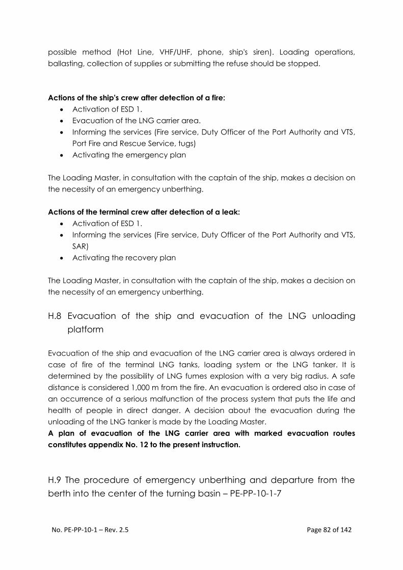
No. PE-PP-10-1 – Rev. 2.5 Page 82 of 142
possible method (Hot Line, VHF/UHF, phone, ship's siren). Loading operations,
ballasting, collection of supplies or submitting the refuse should be stopped.
Actions of the ship's crew after detection of a fire:
Activation of ESD 1.
Evacuation of the LNG carrier area.
Informing the services (Fire service, Duty Officer of the Port Authority and VTS,
Port Fire and Rescue Service, tugs)
Activating the emergency plan
The Loading Master, in consultation with the captain of the ship, makes a decision on
the necessity of an emergency unberthing.
Actions of the terminal crew after detection of a leak:
Activation of ESD 1.
Informing the services (Fire service, Duty Officer of the Port Authority and VTS,
SAR)
Activating the recovery plan
The Loading Master, in consultation with the captain of the ship, makes a decision on
the necessity of an emergency unberthing.
H.8 Evacuation of the ship and evacuation of the LNG unloading
platform
Evacuation of the ship and evacuation of the LNG carrier area is always ordered in
case of fire of the terminal LNG tanks, loading system or the LNG tanker. It is
determined by the possibility of LNG fumes explosion with a very big radius. A safe
distance is considered 1,000 m from the fire. An evacuation is ordered also in case of
an occurrence of a serious malfunction of the process system that puts the life and
health of people in direct danger. A decision about the evacuation during the
unloading of the LNG tanker is made by the Loading Master.
A plan of evacuation of the LNG carrier area with marked evacuation routes
constitutes appendix No. 12 to the present instruction.
H.9 The procedure of emergency unberthing and departure from the
berth into the center of the turning basin – PE-PP-10-1-7

No. PE-PP-10-1 – Rev. 2.5 Page 83 of 142
The Loading Master, in consultation with the captain of the ship, makes a decision on
the necessity of the ship's departure from the terminal in case when its stay in the berth
constitutes a threat to the personnel, the natural environment, the mooring system
and/or the LNG carrier area. It is important that especially in case of rough weather
conditions (strong wind, squals), both ship’s captain and terminal loading master may
consider safer to leave the vessel at berth, assisted by tugs with arms disconnected
then decide to unberth the vessel. St-by tugs will assist the ship and prevent any
uncontrolled movements.
It is advised to consider an emergency unberthing and departure from the berth in
the following cases:
1. Fire at the Terminal.
2. Fire on the LNG tanker.
3. Break away of the ship from the berth.
4. Excess of the operational range of the unloading arms (activation of the first
degree alarm)
5. Activation of ESD 2.
6. An occurrence of boundary conditions of wind velocity for the emergency
unberthing given in the present instruction..
7. LNG leak from the ship system.
8. LNG leak from the terminal system.
If the situation and the time allow it and there is an uninhibited access to the mooring
stations of the LNG tanker, the unberthing should occur after previous loosing of all the
mooring ropes. The Loading Master, after making sure that the tugboats made fast
the emergency towlines or they are connected to sunken bitts, gives an order of
releasing the quick release hooks and informs the captain of the ship about the
possibility of heaving up the mooring ropes on board..
In case when an emergency situation develops dynamically and/or there is no access
to the mooring stations, the quick release hooks can be activated under load
conditions from jetty control room. In that case it is advised to maintain exceptional
caution and under no circumstances get close to the maneuvering boards of the
tanker and the mooring dolphins. A rapid release of energy accumulated in the
loaded mooring lines and caused by the activation of the hook releasing system
constitutes a serious threat to the people located in the nearest surroundings.

No. PE-PP-10-1 – Rev. 2.5 Page 84 of 142
Readiness of the ship, availability of the pilots and towing assistance upon emergency
unberthing
Readiness of the ship
In accordance with the Marine Operations Manual and Safe LNG Carr, it is not allowed
to perform any works on an LNG tanker moored to the terminal that have a negative
influence on the time of readiness of the main engines, the steering engine and the
mooring navigation equipment. In practice, the time needed for attaining such
readiness amounts from 30 minutes which basically eliminates the possibility of using
the native drive in emergency unberthing.
Availability of the pilot
In accordance with the Port Regulations, and consequently the Marine Operations
Manual, the pilot stays on board of the LNG tanker throughout the whole time of the
unloading. The availability of the pilot in case of a necessity of an emergency
unberthing is therefore ensured.
Readiness of the tugboats
In accordance with the Marine Operations Manual, the tugboats must remain in
assistance during the stop of the LNG tanker in the terminal. They moor at the low
berth, about 500 m from the reloading platform. The tugboats are to remain in full
readiness (the so-called Hot Stand-by). After receiving a signal of the necessity of
emergency unberthing, the tugboats immediately go in the direction of the LNG
tanker, connect the emergency towlines (fire wires or sunken bitts), and pull the ship
away from the berth. The remaining tugboats stay in passive assistance and, whenever
needed, they control the moves of the ship in accordance with the directions of the
LNG tanker's captain and the pilot, leading the ship out into the center of the turning
basin. The tugboats keep the Hot Stand-by through conducting constant listening at
a VHF channel established during the pre-discharge meeting.
The fire unit is obliged to obey the same communication regulations as the tugboats.
Coordination of an emergency unberthing from the terminal
A decision on an emergency unberthing is made by the Loading Master in
consultation with the captain of the ship. Whenever it is necessary, the Loading Master
gives an order to activate the quick release hooks system – or from the PNDS control
room (jetty control room).
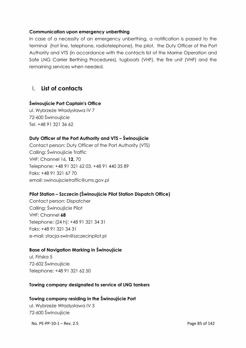
No. PE-PP-10-1 – Rev. 2.5 Page 85 of 142
Communication upon emergency unberthing
In case of a necessity of an emergency unberthing, a notification is passed to the
terminal (hot line, telephone, radiotelephone), the pilot, the Duty Officer of the Port
Authority and VTS (in accordance with the contacts list of the Marine Operation and
Safe LNG Carrier Berthing Procedures), tugboats (VHF), the fire unit (VHF) and the
remaining services when needed.
I. List of contacts
Świnoujście Port Captain's Office
ul. Wybrzeże Władysława IV 7
72-600 Świnoujście
Tel. +48 91 321 36 62
Duty Officer of the Port Authority and VTS – Świnoujście
Contact person: Duty Officer of the Port Authority (VTS)
Calling: Świnoujście Traffic
VHF: Channel 16, 12, 70
Telephone: +48 91 321 62 03, +48 91 440 35 89
Faks: +48 91 321 67 70
email: [email protected]
Pilot Station – Szczecin (Świnoujście Pilot Station Dispatch Office)
Contact person: Dispatcher
Calling: Świnoujście Pilot
VHF: Channel 68
Telephone: (24 h): +48 91 321 34 31
Faks: +48 91 321 34 31
e-mail: [email protected]
Base of Navigation Marking in Świnoujście
ul. Fińska 5
72-602 Świnoujście
Telephone: +48 91 321 62 50
Towing company designated to service of LNG tankers
Towing company residing in the Świnoujście Port
ul. Wybrzeże Władysława IV 3
72-600 Świnoujście

No. PE-PP-10-1 – Rev. 2.5 Page 86 of 142
Telephone: + 48 606 332 129
Municipal Headquarters of the State Fire Service in Świnoujście
Contact person: Duty Officer of the Municipal Control Station
Address: 72-600 Świnoujście, ul. Piastowska 2a
Tel.: +48 91 321 44 08 – head office; +48 91 327 52 10 – secretariat; +48 91 321 44 08 –
Municipal Control Station;
Tel. alarm number: 998 – alarm number MCS;
Fax. +48 91 321 42 89 – secretariat; +48 91 321 42 89 after 3:30 p.m. mon-fri. – MCS
E-mail: [email protected] - MSK
Regional Headquarters of the State Fire Service in Szczecin
Address: ul. Firlika 9-14, 71-637 Szczecin
Telephone: +48 91 480 88 01
Faks: +48 91 480 88 02
e-mail: [email protected]
Municipal Police Headquarters in Świnoujście
Contact person: Duty Officer
Address: 72-600 Świnoujście, ul. Krzywoustego 2a
Telephone: + 48 91 326 75 11
Tel. alarm number: 997, 112
Fax. + 48 91 326 75 13
E-mail: [email protected]
Maritime Border Guard Branch
Pomeranian Border Guard Division
ul. Grodzka 4, 72-600 Świnoujście
Telephone: +48 91 322 52 15
Faks: +48 91 322 52 09
Border Guard Outpost in Świnoujście
Address: ul. Dworcowa 1, 72-606 Świnoujście
Telephone: +48 91 322 72 00;
Faks: +48 91 322 72 05
Voivodeship Office – Regional Crisis Management Center
Contact person: Center Attendant
Address: 70-502 Szczecin, Wały Chrobrego 4
Telephone: +48 91 430 33 42,
Faks: +48 91 433 85 22

No. PE-PP-10-1 – Rev. 2.5 Page 87 of 142
E-mail: [email protected]
Group Duty Worksite
Telephone: +48 91 430 33 42
Mobile tel. no.: +48 696 031 168
Fax. +48 91 433 85 22
Helpline: +48 800 170 010
E-mail: [email protected]
Crisis Management Department (CMD) – Świnoujście
City Hall of Świnoujście
Address: 72-600 Świnoujście, ul. Wojska Polskiego 1/1
Telephone: +48 91 321 44 26, +48 91 322 00 08, +48 91 322 00 09
Faks: 91 321 44 26
email: [email protected]
Maritime Search and Rescue Service SAR
Auxiliary Coordination Center
Address: Świnoujście, ul. Władysława IV 7
Telephone: +48 91 321 49 17
Faks: +48 91 321 59 29
Mobile: +48 505 050 969
Maritime Search and Rescue Service SAR
Contact person: Duty officer of the Maritime Rescue Coordination Center
Address: Gdynia, ul. Hryniewieckiego 10
Telephone: +48 58 620 55 51
Telephone: +48 58 620 55 51
Mobile: +48 505 050 971
Port Rescue Service
Contact person: Duty Officer
Address: Szczecin, ul. Bytomska 1
Tel. (24 h): +48 91 430 82 55
Alarm Point:
Telephone: +48 91 430 89 98, +48 91 430 83 55,
Faks: +48 91 462 41 12,
e-mail: [email protected]
Commandant
Telephone: +48 91 430 82 55,
Mobile: +48 601 722 849,
e-mail: [email protected]

No. PE-PP-10-1 – Rev. 2.5 Page 88 of 142
Fireboat STRAŻAK 26 – Świnoujście
Telephone: +48 661 408 640
Regional Emergency Ambulance Service Station in Szczecin
Duty Service Tel. 999, 112
Address: 70-526 Szczecin, ul. Mazowiecka 14
Tel. 24 h 999, 112
Emergency Ambulance Service of the Independent Public Health Care Center in the
Alfred Sokołowski Municipal Hospital in Świnoujście
Address: ul. Mieszka I 7, Świnoujście
Telephone: +48 91 321 41 74
Szczecin and Świnoujście Seaport Authority
Contact person: Main Port Dispatcher
Szczecin, ul. Bytomska 7
Tel: (24 h) 91 430 83 71,
Mobile tel. no.: 46 34
e-mail: [email protected]

No. PE-PP-10-1 – Rev. 2.5 Page 89 of 142
J. Appendices.
J.1 Appendix No. 1 – List of documents – PE-PP-10-1-W1
CHPP
PN-EN ISO 28460 Petroleum and natural gas industries. Installation and
equipment for liquefied natural gas. Ship-to-shore interface
and port operations
2013
PN-EN 1473 Installations and Equipment for Liquefied Natural Gas.
PN-EN 13852-
1:2013.
Off-shore lifting equipment requirements
Major Accident Hazards of Certain Industrial Activities -
European Council Directive - Official Journal of the KIA
5697/590EK 405B, rev. KIA 12044/613/2007
2000
EN 1532 Installations and Equipment for Liquefied Natural Gas - Ship
to Shore Interface - 1997 - European Standard -
1997
INTERNATIONAL MARITIME ORGANIZATION
IMO290E Revised Recommendations on the Safe Transport of
Dangerous Cargoes and Related Activities
2007
IMO D11QE International Convention for the Safety of Life at Sea
(SOLAS)
2004
IMO 172E SOLAS Amendments 2003, 2004, 2005 2006
IMO 173E SOLAS Amendments 2006 2007
IMO 479E Convention Compensation on Liability for Damage in
Connection from Car.Haz. / Noxious (HNS Convention)
1997
IMO 117E International Safety Management Code (ISM & Guidelines
for Implement of the ISM)
2002
IMO Code for Existing Ships Carrying Liquefied Gases in Bulk
(Existing Ship Code)
1976
IMO Code for the Construction and Equipment of Ships Carrying
Liquefied Gases in Bulk (GC Code)
1993
IMO International Code for the Construction and Equipment of
Ships Carrying Liquefied Gases in Bulk (IGC Code)
1993
ISPS ISPS CODE 2004
STANDARD INDUSTRY GUIDELINES
WL004 Liquefied Gas Handling Principles on Ships and in Terminals 2000
OCIMF Mooring Equipment Guidelines – 3rd Edition 2008
OCIMF International Safety Guide for Oil Tankers and Terminals 2006

No. PE-PP-10-1 – Rev. 2.5 Page 90 of 142
Installations and Equipment for Liquefied Natural Gas - Ship
to Shore Interface - 1997 - European Standard - EN 1532
1997
WM040 Mooring Equipment Guidelines 2008
SIGTTO Ship Information Questionnaire for Gas Carriers 1998
SIGTTO The Training of Terminal Staff involved in the Loading and
Discharging of Gas Carriers
1996
WG061 Guide to Contingency Planning for Marine Terminals
Handling Liquefied Gases in Bulk
2001
NI Tug Use in Port (A Practical Guide) 2003
ICS Tanker Safety Guide (Liquefied Gas) - International
Chamber of Shipping - 1995
1995
OCIMF Safety Guide for Terminals Handling Ships Carrying
Liquefied Gases in Bulk - OCIMF - 1993
1993
SIGTTO Ship/Shore interface Communications Necessary for
Matching Ship to Berth - SIGTTO - 1997.
1997
SIGTTO Recommendations for Manifolds for Refrigerated Liquefied
Natural Gas Carriers (LNG) - SIGTTO - 1994
1984
SIGTTO ISGOTT 5th edition 2006
SIGTTO Guide to Contingency Planning for Marine Terminals
Handling Liquefied Gases in Bulk-2nd edition
2001
SIGTTO LNG Operations in Port Areas 2003
SIGTTO Liquefied Gas Handling Principles on Ships and in Terminals
- 3rd edition
2000
SIGTTO Training of Terminal Staff involved in Loading and
Discharging Gas Carrier
1996
SIGTTO Jetty Maintenance and Inspection Guide 2008
SIGTTO Ship Vetting and its Application to LNG 2004
GIIGNL LNG Custody Transfer Handbook 2011
INDUSTRY RECOMMENTATIONS
SIGTTO Rollover Prevention - A Review of Causes, Methods for
Prevention and Damage Limitation Measures
1993
SIGTTO Site Selection and Design for LNG Ports and Jetties 1997
SIGTTO Accident Prevention - The Use of Hoses & Hard Arms at
Marine Terminals Handling Liquefied Gases
1996

No. PE-PP-10-1 – Rev. 2.5 Page 91 of 142
J.2 Appendix No. 2 – SSSCL with filling instruction – PE-PP-10-1-F-1
The Ship/Shore Safety Check List (Lista Kontrolna Bezpieczeństwa Statek/Terminal)
PE-PP-10-1-F-1

No. PE-PP-10-1 – Rev. 2.5 Page 92 of 142
Characteristics, issues, distribution and revision of the document
Characteristics of the document
Related area Marine Operations
Category:
Concept owner
Developed by – date, name and last name 20/02/2014, Adam Łupkowski
Verified by – range, date, name and last
name Jacek Banaszek
Verified by – range, date, name and last
name Marcin Palczyński
Approved by – date, name and last name Janusz Kurmański
Related internal regulations Terminal Service Manual, Marine
Operation and Safe Berthing Manual
Classification
Issues of the document
Issue no. Issue date Distribution
Orginal Copy 1 Copy 2 Copy 3
Revisions – updates, reviews, audits
Revision
number
Entry
date
Scope of update, review, audit
Description of changes made
Date, name, last
name (person
making the entry)
No. PE-PP-10-1 – Rev. 2.5 Page 93 of 142
Emergency Actions
(Działania w sytuacji zagrożenia)
The actions to be taken in the event of an emergency at a terminal should be
contained in the terminal’s emergency plan. Particular attention should be given to
factors to be taken into consideration when deciding whether or not to remove a ship
from the berth in the event of an emergency. (Działania jakie musza zostać podjęte
w przypadku sytuacji awaryjnej na terminalu powinny być zawarte w planie
awaryjnym terminala. W przypadku poważnego zagrożenia bezpieczeństwa należy
rozważyć awaryjne odholowanie statku od nabrzeża).
Fire or Explosion on a Berth
(Pożar lub wybuch na nabrzeżu)
Action by Ships: Should a fire or explosion occur on a berth, the ship or ships at the
berth must immediately report the incident to the terminal control room by the
quickest possible method (VHF/UHF, telephone contact, sounding ship’s siren etc). All
cargo, bunkering, deballasting and tank cleaning operations should be shut down
and all cargo arms or hoses should be drained ready for disconnection. The ship’s fire-
mains should be pressurised and water fog applied in strategic places. The ship’s
engines, steering gear and unmooring equipment must be brought to a state of
immediate readiness. A pilot ladder should be deployed on the offshore side. (W
przypadku pożaru lub wybuchu na nabrzeżu statek ma obowiązek
natychmiastowego powiadomienia sterowni głównej terminalu najszybszą możliwą
metodą (VHF/UHF, telefon, syrena statkowa). Operacje ładunkowe i balastowe musza
zostać natychmiast przerwane, a ramiona rozładowcze zdrenowane i przygotowane
do awaryjnego rozłączenia. Statkowa instalacja ppoż. powinna być utrzymywana
pod ciśnieniem, a odpowiedni system ppoż. (w przypadku LNG – proszkowy) powinien
być gotowy do natychmiastowego użycia. Silnik główny, maszynka sterowa i system
cumowniczy powinny być w stanie natychmiastowej gotowości. Od strony wody
powinien zostać przygotowany sztormtrap pilotowy).
Fire on a Tanker at a Terminal
(Pożar na zbiornikowcu przy terminalu)
If a fire breaks out on a tanker while at a terminal, the tanker must raise the alarm by
sounding the recognized alarm signal consisting of a series of long blasts on the ship’s
whistle, each blast being not less than 10 seconds in duration unless the terminal has
notified the ship of some other locally recognised alarm signal. All cargo, bunkering or
ballasting operations must be stopped. (W przypadku pożaru na zbiornikowcu załoga
ma obowiązek podnieść alarm za pomocą uzgodnionego wcześniej sygnału

No. PE-PP-10-1 – Rev. 2.5 Page 94 of 142
składającego się z serii długich, trwających co najmniej 10 sekund, dźwięków
nadanych syreną okrętową – jeśli nie ustalono innego sygnału. Operacje ładunkowe
i balastowe muszą zostać wstrzymane, a statkowy plan awaryjny (contingency plan)
wcielony w życie).
Ship’s Name
(Nazwa statku)
Terminal Name & Berth No.
(Nazwa i numer nabrzeża)
Date of Arrival
(Data zawinięcia)
Port
Time of Arrival
(Czas zawinięcia)
Instructions for completion
(Instrukcja wypełniania)
The safety of operations requires that all questions should be answered affirmatively
by clearly ticking (v) the appropriate box. If an affirmative answer is not possible, the
reason should be given and agreement reached upon appropriate precautions to be
taken between the ship and terminal. Where any question is consider to be not
applicable, then a note to that effect should be inserted in the remarks column.
(Bezpieczeństwo operacji wymaga udzielenia odpowiedzi na wszystkie pytania i
postawienie znaku (v) w odpowiednim polu. Jeśli udzielenie pozytywnej odpowiedzi
jest niemożliwe, powinien być podany tego powód oraz musi nastąpić odpowiednie
uzgodnienie między statkiem i terminalem).
A box in the columns „Ship” and „Terminal” indicates that checks should be carried
out by the party concerned.
(Pola w kolumnach “Statek” i “Terminal” wskazują która strona przeprowadza kontrolę
spełnienia wymogów danego punktu).
The presence of the letters A, P or R in the column code indicates the following:
(Litery A, P i R postawione w kolumnie „Litery kodu” oznaczają odpowiednio):
A – Any procedures and agreement which should be in writing in the remarks column
of this check list or other mutually acceptable form. In other case, the signature of
both parties should be required.
(Litera ta oznacza, że dane ustalenie wymaga formy pisemnej w kolumnie ”Uwagi”
lub innej wzajemnie akceptowalnej formy ustalenia. W przeciwnym wypadku
wymagany jest podpis obydwu stron).

No. PE-PP-10-1 – Rev. 2.5 Page 95 of 142
P – In the case of negative answer the operation should not be carried out whit out
the permission of the Port Authority.
(Litera ta oznacza, że w przypadku negatywnej odpowiedzi operacja nie może być
prowadzona bez zgody Kapitanatu Portu).
R – Indicated items to be rechecked at intervals not exceeding that, agreed in the
declaration.
(Litera ta wskazuje konieczność dokonywania sprawdzeń w zadeklarowanych
odstępach czasu).
Ship/Shore Safety Check List
(Lista Kontrolna Bezpieczeństwa Statek/Terminal)
Part ‘A’ - Bulk Liquid General – Physical Checks
(Część ‘A’ Sprawdzenia ogólne dla ładunków płynnych – fizyczna weryfikacja)
No.
(Lp.)
General
(Pytania ogólne)
Ship
(Statek
)
Terminal
(Termin
al)
Code
(Kod)
Remarks
(Uwagi)
1
1. There is safe access between
the ship and shore. (Zapewniono
bezpieczny dostęp pomiędzy
statkiem i nabrzeżem).
R
2
The ship is securely moored.
(Statek został bezpiecznie
zacumowany).
R
3
The agreed ship/shore
communication system is
operative.(Uzgodniony system
łączności statek/terminal jest
sprawny).
A R
System:
Backup
System:
4
Emergency towing-off pennants
are correctly rigged and
positioned. (Awaryjne liny
holownicze zostały prawidłowo
zamocowane).
R
5
The ship’s fire hoses and fire-
fighting equipment are positioned
and ready for immediate use.
(Statkowe węże I sprzęt p.poż. są
właściwie rozlokowane).
R

No. PE-PP-10-1 – Rev. 2.5 Page 96 of 142
6
The terminal’s fire-fighting
equipment is positioned and
ready for immediate use. (Sprzęt
p.poż. terminalu jest gotowy do
użycia).
R
7
The ship’s cargo and bunker
hoses, pipelines and manifolds
are in good condition, properly
rigged and appropriate for the
service intended. (Statkowe węże
ładunkowe i bunkrowe oraz
rurociągi i manifoldy są w dobrym
stanie – gotowe do użycia).
8
The terminal’s cargo and bunker
hoses or arms are in good
condition, properly rigged and
appropriate for the service
intended. (Węże ładunkowe i
bunkrowe oraz rurociągi i
manifoldy terminalu są w dobrym
stanie – gotowe do użycia).
9
The cargo transfer system is
sufficiently isolated and drained
to allow safe removal of blank
flanges prior to connection.
(System ładunkowy statku jest
zdrenowany i odizolowany, aby
umożliwić bezpieczne usuniecie
flansz zaślepiających).
10
Scuppers and save-alls on board
are effectively plugged and drip
trays are in position and empty.
(Szpigaty są odpowiednio
zakorkowane, a wanienki
przeciwrozlewowe puste).
R
11
Temporarily removed scupper
plugs will be constantly
monitored. (Czasowo
rozszczelnione szpigaty będą
stale monitorowane).
R

No. PE-PP-10-1 – Rev. 2.5 Page 97 of 142
12
Shore spill containment and
sumps are correctly managed.
(Wanny i inne przestrzenie
przeciwrozlewowe terminalu są
właściwie przygotowane).
R
13
The ship’s unused cargo and
bunker connections are properly
secured with blank flanges fully
bolted. (Nieużywane linie
ładunkowe i bunkrowe są
odpowiednio zaślepione –
wszystkie śruby w miejscu).
14
The terminal’s unused cargo and
bunker connections are properly
secured with blank flanges fully
bolted. (Nieużywane linie
ładunkowe i bunkrowe są
odpowiednio zaślepione –
wszystkie śruby w miejscu).
15
All cargo, ballast and bunker tank
lids are closed. (Wszystkie włazy
do zbiorników ładunkowych,
balastowych i paliwowych są
zamknięte).
16
Sea and overboard discharge
valves, when not in use, are
closed and visibly secured.
(Zawory wody morskiej, które nie
są w użyciu są zamknięte i
zabezpieczone).
17
All external doors, ports and
windows in the accommodation,
stores and machinery spaces are
closed. Engine room vents may
be open. (Wszystkie drzwi, okna i
otwory nadbudówki i siłowni są
zamknięte – wentylacja siłowni
może być otwarta).
R
18
The ship’s emergency fire control
plans are located externally.
(Statkowe plany p.poż. znajdują
Location:
(Lokalizacja)
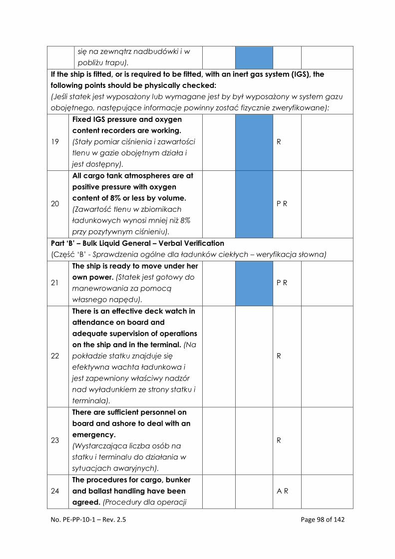
No. PE-PP-10-1 – Rev. 2.5 Page 98 of 142
się na zewnątrz nadbudówki i w
pobliżu trapu).
If the ship is fitted, or is required to be fitted, with an inert gas system (IGS), the
following points should be physically checked:
(Jeśli statek jest wyposażony lub wymagane jest by był wyposażony w system gazu
obojętnego, następujące informacje powinny zostać fizycznie zweryfikowane):
19
Fixed IGS pressure and oxygen
content recorders are working.
(Stały pomiar ciśnienia i zawartości
tlenu w gazie obojętnym działa i
jest dostępny).
R
20
All cargo tank atmospheres are at
positive pressure with oxygen
content of 8% or less by volume.
(Zawartość tlenu w zbiornikach
ładunkowych wynosi mniej niż 8%
przy pozytywnym ciśnieniu).
P R
Part ‘B’ – Bulk Liquid General – Verbal Verification
(Część ‘B’ - Sprawdzenia ogólne dla ładunków ciekłych – weryfikacja słowna)
21
The ship is ready to move under her
own power. (Statek jest gotowy do
manewrowania za pomocą
własnego napędu).
P R
22
There is an effective deck watch in
attendance on board and
adequate supervision of operations
on the ship and in the terminal. (Na
pokładzie statku znajduje się
efektywna wachta ładunkowa i
jest zapewniony właściwy nadzór
nad wyładunkiem ze strony statku i
terminala).
R
23
There are sufficient personnel on
board and ashore to deal with an
emergency.
(Wystarczająca liczba osób na
statku i terminalu do działania w
sytuacjach awaryjnych).
R
24
The procedures for cargo, bunker
and ballast handling have been
agreed. (Procedury dla operacji
A R

No. PE-PP-10-1 – Rev. 2.5 Page 99 of 142
wyładunku, bunkrowania i
balastowania zostały uzgodnione).
25
The emergency signal and
shutdown procedure to be used by
the ship and shore have been
explained and understood.
(Sygnały alarmowe i procedura
awaryjnego przerwania wyładunku
zostały wyjaśnione i przyjęte do
wiadomości).
A
26
Material Safety Data Sheets (MSDS)
for the cargo transfer have been
exchanged where requested.
(Karty substancji niebezpiecznych
zostały wymienione zgodnie z
życzeniem stron).
P R
27
The hazards associated with toxic
substances in the cargo being
handled have been identified and
understood. (Niebezpieczeństwa
związane z wyładunkiem LNG
zostały zidentyfikowane).
H2S Content:
(Stężenie
H2S)
Benzene
Content
(Stęż.
benzenu)
28
An International Shore Fire
Connection has been provided.
(Międzynarodowy łącznik
pożarowy jest dostępny).
29
The agreed tank venting system will
be used.
(Uzgodniony system wentylacji
zbiorników).
A R Method:
30
The requirements for closed
operations have been agreed.
(Wymogi odnośnie “operacji
zamkniętej” zostały uzgodnione).
R
31
The operation of the P/V system has
been verified.
(Działanie system P/V zostało
zweryfikowane).

No. PE-PP-10-1 – Rev. 2.5 Page 100 of 142
32
Where a vapour return line is
connected, operating parameters
have been agreed. (Gdy linia
powrotu par ładunku jest
podłączona uzgodniono jej
parametry operacyjne).
A R
33
Independent high level alarms, if
fitted, are operational and have
been tested. (Przetestowano
działanie niezależnego systemu
ostrzegania przed wysokim
poziomem zbiorników).
A R
34
Adequate electrical insulating
means are in place in the
ship/shore connection.
(Zapewniono wyrównanie
ładunków elektrycznych między
statkiem, a terminalem).
A R
35
Shore lines are fitted with a non-
return valve, or procedures to
avoid back filling have been
discussed. (Linie ładunkowe
terminalu posiadają zawory
zwrotne lub uzgodniono procedurę
zabopiegania cofaniu się ładunku).
P R
36
Smoking rooms have been
identified and smoking
requirements are being observed.
(Wyznaczono pomieszczenia dla
palących).
A R
Nominated
smoking
rooms:
37
Naked light regulations are being
observed. (Zakaz używania
otwartego ognia jest
przestrzegany).
A R
38
Ship/Shore telephones, mobile
phones and pager requirements
are being observed. (Zakaz
używania telefonów komórkowych
i pagerów jest przestrzegany).
A R

No. PE-PP-10-1 – Rev. 2.5 Page 101 of 142
39
Hand torches (flashlights) are of an
approved type. (Latarki używanie
na statku i na terminalu są
właściwego typu).
40
Fixed VHF/UHF transceivers and AIS
equipment are on the correct
power mode or switched off.
(Stacje VHF/UHF i AIS mają
zredukowaną moc emisji lub są
wyłączone).
41
Portable VHF/UHF transceivers are
of an approved type. (Przenośne
urządzenia VHF/UHF są
odpowiedniego typu).
42
The ship’s main radio transmitter
aerials are earthed and radars are
switched off. (Anteny MF/HF są
uziemione, a radary wyłączone).
43
Electric cables to portable
electrical equipment within the
hazardous area are disconnected
from power. (Przenośne urządzenia
elektryczne w strefie niebezpiecznej
są odłączone od sieci).
44
Window type air conditioning units
are disconnected. (Agregaty
klimatyzatorów znajdujące się na
zewnątrz są wyłączone).
45
Positive pressure is being
maintained inside the
accommodation, and air
conditioning intakes, which may
permit the entry of cargo vapours,
are closed. (Wewnątrz nadbudówki
jest utrzymywane dodatnie
ciśnienie, a wloty powietrza do
klimatyzacji, które mogą
spowodować zassanie par ładunku
są zamknięte).

No. PE-PP-10-1 – Rev. 2.5 Page 102 of 142
46
Measures have been taken to
ensure sufficient mechanical
ventilation in the pumproom.
(Przedsięwzięto środki w celu
zapewnienia wystarczającej
wentylacji pompowni).
R
47
There is provision for an emergency
escape. (Istnieje alternatywna
droga ewakuacji).
48
The maximum wind and swell
criteria for operations have been
agreed. (Graniczne wartośći wiatru
i falowania zostały uzgodnione).
A
49
Security protocols have been
agreed between the Ship Security
Officer and the Port Facility Security
Officer, if appropriate. (Zasady
ochrony zostały uzgodnione
między SSO, a PFSO)
A
50
Where appropriate, procedures
have been agreed for receiving
nitrogen supplied from shore, either
for inerting or purging ship’s tanks,
or for line clearing into the ship.
(Uzgodniono procedury
azotowania do inertowania lub
przedmuchu zbiorników)
A P
If the ship is fitted, or is required to be fitted, with an inert gas system (IGS) the
following
statements should be addressed:
(Jeśli statek jest wyposażony lub jest wymagane by był wyposażony w system gazu
obojętnego, następujące fakty powinny zostać potwierdzone):
51
The IGS is fully operational and in
good working order. (System gazu
obojętnego jest w pełni sprawny i
w dobrym stanie technicznym)
P
52
Deck seals, or equivalent, are in
good working order. (Deck seal lub
jego odpowiednik są w dobrym
stanie technicznym).
R

No. PE-PP-10-1 – Rev. 2.5 Page 103 of 142
53
Liquid levels in pressure/vacuum
breakers are correct. (Poziomy
cieczy w P/V brakerach są
prawidłowe).
R
54
The fixed and portable oxygen
analysers have been calibrated
and are working properly.
(Stacjonarne i przenośne
analizatory atmosfery zostały
skalibrowane i działają
prawidłowo).
R
55
All the individual tank IG valves (if
fitted) are correctly set and locked.
(Indywidualne zawory odcinające
gazu obojętnego (Jeśli
zainstalowane) są odpowiednio
ustawione i zablokowane).
R
56
All personnel in charge of cargo
operations are aware that, in the
case of failure of the inert gas plant,
discharge operations should cease
and the terminal be advised.
(Personel nadzorujący operacje
ładunkowe jest świadomy
konieczności przerwania operacji i
powiadomienia terminalu w
przypadku awarii systemu gazu
obojętnego)
The COW section – Intentionally omitted as N/A throughout for LNG operations.
(Część dotycząca COW została celowo pominięta, gdyż nie odnosi się do operacji
LNG)
Part ‘C’ – Bulk Liquid Chemicals – Verbal Verification – Intentionally omitted as N/A
throughout for LNG operations.
(Część ‘C’ – Ciekłe chemikalia – weryfikacja słowna – celowo pominięto jako nie
odnoszące się do operacji LNG)
Part ‘D’ – Bulk Liquefied Gases – Verbal Verification
(Część ‘D’ – Gazy skroplone luzem – Weryfikacja słowna)
1
Material Safety Data Sheets are
available giving the necessary
data for the safe handling of the
cargo. (Karty substancji

No. PE-PP-10-1 – Rev. 2.5 Page 104 of 142
niebezpiecznych są dostępne i
zawierają niezbędne informacje do
bezpiecznego przeładunku).
2
A manufacturer’s inhibition
certificate, where applicable, has
been provided. (Certyfikat
inhibitora wydany przez
załadowcę, gdy jest to właściwe).
P
3
The water spray system is ready for
immediate use. (System zraszaczy
pokładowych gotowy do
natychmiastowego użycia).
4
There is sufficient suitable
protective equipment (including
self-contained breathing
apparatus) and protective clothing
ready for immediate use.
(Dostępna jest wystarczająca ilość
odpowiedniego wyposażenia
ochronnego (włączając aparaty
oddechowe) i ubrań ochronnych.
5
Hold and inter-barrier spaces are
properly inerted or filled with dry
air, as required. (Hold space i IBS są
właściwie zainertowane/
zaazotowane lub wypełnione
suchym powietrzem).
6
All remote control valves are in
working order. (Wszystkie zawory
zdalnie kontrolowane są w dobrym
stanie technicznym).
7
The required cargo pumps and
compressors are in good order,
and the maximum working
pressures have been agreed
between ship and shore. (Pompy
ładunkowe i kompresory są w pełni
sprawne, a maksymalne ciśnienia
operacyjne zostały uzgodnione
między statkiem, a terminalem).
A

No. PE-PP-10-1 – Rev. 2.5 Page 105 of 142
8
Re-liquefaction or boil-off control
equipment is in good order.
(System ponownego skraplania
BOG oraz system kontroli przepływu
i ciśnienia BOG są w pełni
sprawne).
9
The gas detection equipment has
been properly set for the cargo, is
calibrated, has been tested and
inspected and is in good order.
(Urządzenia wykrywacze gazu
zostały prawidłowo ustawione,
skalibrowane, przetestowane,
sprawdzone i są w dobrym stanie
technicznym).
10
Cargo system gauges and alarms
are correctly set and in good order.
(Wskaźniki poziomu ładunku i
alarmy są odpowiednio ustawione i
w pełni sprawne).
11
Emergency shutdown systems have
been tested and are working
properly. (Systemy awaryjnego
zatrzymania wyładunku zostały
przetestowane i działają
prawidłowo).
12
Ship and shore have informed each
other of the closing rate of ESD
valves, automatic valves or similar
devices. (Przedstawiciele statku i
terminal poinformowali się
wzajemnie o czasach zamknięcia
zaworów ESD, zaworów
automatycznych lub podobnych
urządzeń).
A
Ship:
Shore:
13
Information has been exchanged
between ship and shore on the
maximum / minimum
temperatures/pressures of the
cargo to be handled. (Wymieniono
informacje statek /terminal na
A
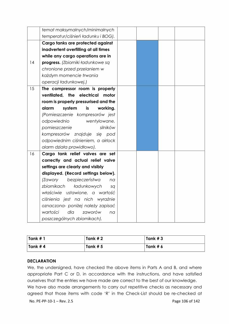
No. PE-PP-10-1 – Rev. 2.5 Page 106 of 142
temat maksymalnych/minimalnych
temperatur/ciśnień ładunku i BOG).
14
Cargo tanks are protected against
inadvertent overfilling at all times
while any cargo operations are in
progress. (Zbiorniki ładunkowe są
chronione przed przelaniem w
każdym momencie trwania
operacji ładunkowej.)
15 The compressor room is properly
ventilated, the electrical motor
room is properly pressurised and the
alarm system is working.
(Pomieszczenie kompresorów jest
odpowiednio wentylowane,
pomieszczenie silników
kompresorów znajduje się pod
odpowiednim ciśnieniem, a airlock
alarm działa prawidłowo).
16 Cargo tank relief valves are set
correctly and actual relief valve
settings are clearly and visibly
displayed. (Record settings below).
(Zawory bezpieczeństwa na
zbiornikach ładunkowych są
właściwie ustawione, a wartość
ciśnienia jest na nich wyraźnie
oznaczona- poniżej należy zapisać
wartości dla zaworów na
poszczególnych zbiornikach).
Tank # 1 Tank # 2 Tank # 3
Tank # 4 Tank # 5 Tank # 6
DECLARATION
We, the undersigned, have checked the above items in Parts A and B, and where
appropriate Part C or D, in accordance with the instructions, and have satisfied
ourselves that the entries we have made are correct to the best of our knowledge.
We have also made arrangements to carry out repetitive checks as necessary and
agreed that those items with code ‘R’ in the Check-List should be re-checked at

No. PE-PP-10-1 – Rev. 2.5 Page 107 of 142
intervals not exceeding _____ hours. If to our knowledge the status of any item
changes, we will immediately inform the other party.
(Oświadczenie)
(My niżej podpisani zweryfikowaliśmy zapisy części A i B oraz, gdy było to właściwe dla danej operacji części C lub D,
zgodnie z instrukcją wypełniania SSSCL i upewniliśmy się, że zapisy jakich dokonaliśmy są poprawne i zgodnie z naszą
najlepszą wiedzą. Zgodziliśmy się także dokonywać okresowych sprawdzeń stanu faktycznego wszystkich zapisów
oznaczonych literą ‘R’ – powinny one być weryfikowane w odstępach czasowych nie przekraczających ____ godzin.
Jeśli zgodnie z wiedzą którejś ze stron stan faktyczny jakiegokolwiek ustalenia/zapisu ulegnie zmianie zobowiązuje się
ona niezwłocznie powiadomić o tym drugą stronę).
For Ship
(Upoważniony przedstawiciel statku)
For Terminal
(Upoważniony przedstawiciel terminalu)
Name:
Rank:
Signature:
Date:
Time:
Name:
Position or Title:
Signature:
Date:
Time:
Record of repetitive checks:
Date:
Time:
Initials
for Ship:
Initials
for
Shore:

No. PE-PP-10-1 – Rev. 2.5 Page 108 of 142
J.3 Appendix No. 3 Checklist – Pre-discharge meeting – PE-PP-10-1-F-2
CHECKLIST Pre-discharge meeting – Meeting Agenda
LNG Terminal Świnoujście Ship:
Date:
GENERAL
INFORMATION
1 VHF communication has been checked YES NO
2 Hot line and telephone line have been checked YES NO
3 Is gas burning planned during the unloading? YES NO
4 CTM has been opened (before the ESD test) YES NO
5 Warm ESD will be given off by the SHIP
TERMIN
AL
6 Number of ESD Tests
7 Pressure in the ship's tanks kPa
8 Pressure in the terminal's tanks kPa
VAPOR RETURN
9 Vapor return valve open after CTMS (before the
unloading test)
YES NO
10 Vapor flow control at the side of the SHIP
TERMIN
AL.
11 Maximum vapor pressure kPa
COOLING
12 Rate of arms cooling flow m3/h
13 Rate of arms cooling temperature 0C/min
14 Number of arms used in the unloading
UNLOADING
15 Amount of cargo to be unloaded
16 Complete unloading rate
17 Single pump capacity
18 Pressure of pump shutdown

No. PE-PP-10-1 – Rev. 2.5 Page 109 of 142
19 Number of pumps/tanks unloaded simultaneously
20 Unloading rate control SHIP
TERMIN
AL.
21 Expected time of unloading
22 Information about the start of each pump 5
minutes before
YES
23 Information about the stop of each pump 5
minutes before
YES
24 Information about the stabilization of the
unloading rate
YES
25 Information about 25%, 50%, and 75% of the total
unloading volume 10 minutes before
YES
26 Information about the halt of each pump 5
minutes before
YES
AFTER THE
UNLOADING
27 Expected time of arms drainage
28 Vapor return valve closed before CTM (after the
unloading)
YES NO
29 Expected time of N2 blow-through and
disconnection of the arms
30 Expected time of arms disconnection
TERMINAL LOADING MASTER SHIP’S MASTER/CHIEF OFFICER

No. PE-PP-10-1 – Rev. 2.5 Page 110 of 142
J.4 Appendix No. 4 – Safety Letter – PE-PP-10-1-F-4
Safety Letter
Dear Sir,
Responsibility for the safe conduct of operations while your ship is at this terminal
rests jointly with you, as Master of the ship, and with the responsible Terminal
Representative. We wish, therefore, before operations start, to seek your full co-
operation and understanding on the safety requirements set out in the Ship/Shore
Safety Check-List, which are based on safe practices that are widely accepted by the
oil and tanker industries. We expect you, and all under your command, to adhere
strictly to these requirements throughout your ship’s stay alongside this terminal and
we, for our part, will ensure that our personnel do likewise, and co-operate fully with
you in the mutual interest of safe and efficient operations. Before the start of
operations, and from time to time thereafter, for our mutual safety, a member of the
terminal staff, where appropriate together with a Responsible Officer, will make a
routine inspection of your ship to ensure that elements addressed within the scope of
the Ship/Shore Safety Check-List are being managed in an acceptable manner.
Where corrective action is needed, we will not agree to operations commencing or,
should they have been started, we will require them to be stopped. Similarly, if you
consider that safety is being endangered by any action on the part of our staff or by
any equipment under our control, you should demand immediate cessation of
operations. There can be no compromise with safety. Please acknowledge receipt of
this letter by countersigning and returning the attached copy.
Terminal Representative
Terminal Representative on duty is:
Position or Title:
Contact Details:
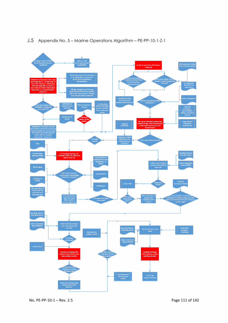
No. PE-PP-10-1 – Rev. 2.5 Page 111 of 142
J.5 Appendix No. 5 – Marine Operations Algorithm – PE-PP-10-1-Z-1

No. PE-PP-10-1 – Rev. 2.5 Page 112 of 142
J.6 Appendix No. 6 Notification of Departure from the Port of Loading – PE-PP-10-1-
F5
LNG Carrier Name and IMO number:
Cargo ID:
Load Port:
Load port Departure Time and Date:
Estimated Time of Arrival (ETA) at the Pilot Boarding Station:
Quantity of LNG loaded in m3 (total):
Vapour pressure:
Temperature of the liquid:
Quality of the LNG loaded:
Value at Load Port:
Wobbe Index:
Gross calorific value of LNG:
Density of LNG at Load Port:
PPM sulfur in LNG at Load port:
Components % Mol of
chemical
components
Units Value at Load Port
Methane (CH4)
Ethane (C2H6)
Propane (C3H8)
Iso Butane (i-C4H10)
N-Butane (n-C4H10)
Iso Pentane (i-C5H12)
N-Pentane (n-C5H12)
N-Hexane (n-C6H14)
Nitrogen (N2)
Oxygen (O2)
Carbon dioxide (CO2)

No. PE-PP-10-1 – Rev. 2.5 Page 113 of 142
Quantity of LNG to be unloaded in m3 (less fuel & boil off during the voyage):
Quantity of LNG to be unloaded in MWh (less fuel & boil off during the voyage):
Other remarks (e.g. factors affecting voyage time or unloading rate):
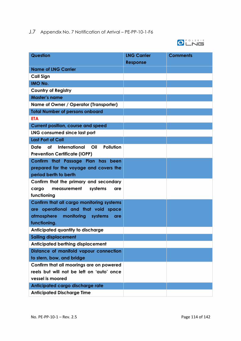
No. PE-PP-10-1 – Rev. 2.5 Page 114 of 142
J.7 Appendix No. 7 Notification of Arrival – PE-PP-10-1-F6
Question LNG Carrier
Response
Comments
Name of LNG Carrier
Call Sign
IMO No.
Country of Registry
Master’s name
Name of Owner / Operator (Transporter)
Total Number of persons onboard
ETA
Current position, course and speed
LNG consumed since last port
Last Port of Call
Date of International Oil Pollution
Prevention Certificate (IOPP)
Confirm that Passage Plan has been
prepared for the voyage and covers the
period berth to berth
Confirm that the primary and secondary
cargo measurement systems are
functioning
Confirm that all cargo monitoring systems
are operational and that void space
atmosphere monitoring systems are
functioning.
Anticipated quantity to discharge
Sailing displacement
Anticipated berthing displacement
Distance of manifold vapour connection
to stern, bow, and bridge
Confirm that all moorings are on powered
reels but will not be left on ‘auto’ once
vessel is moored
Anticipated cargo discharge rate
Anticipated Discharge Time

No. PE-PP-10-1 – Rev. 2.5 Page 115 of 142
Ship’s deficiencies that would affect port
performance including the need for
repairs
Requirements for nitrogen, fuel, water,
stores garbage removal that will be taken
from third parties
Cargo density in KG/M³
Cargo Temperature
Anticipated Saturated Vapour Pressure on
arrival
Ship Inmarsat No’s: Voice No.
Voice No.
Fax No.
Telex No.
Ship GSM : Mobile Phone No
Ship Email:
MMSI No.

No. PE-PP-10-1 – Rev. 2.5 Page 116 of 142
J.8 Appendix No. 8 – SSI current SIGTTO format – PE-PP-10-1-F-3 – for reference only

No. PE-PP-10-1 – Rev. 2.5 Page 117 of 142

No. PE-PP-10-1 – Rev. 2.5 Page 118 of 142
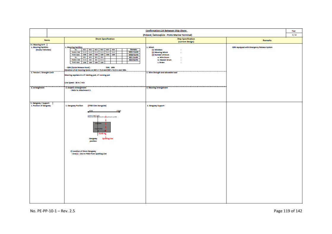
No. PE-PP-10-1 – Rev. 2.5 Page 119 of 142

No. PE-PP-10-1 – Rev. 2.5 Page 120 of 142

No. PE-PP-10-1 – Rev. 2.5 Page 121 of 142

No. PE-PP-10-1 – Rev. 2.5 Page 122 of 142

No. PE-PP-10-1 – Rev. 2.5 Page 123 of 142

No. PE-PP-10-1 – Rev. 2.5 Page 124 of 142

No. PE-PP-10-1 – Rev. 2.5 Page 125 of 142
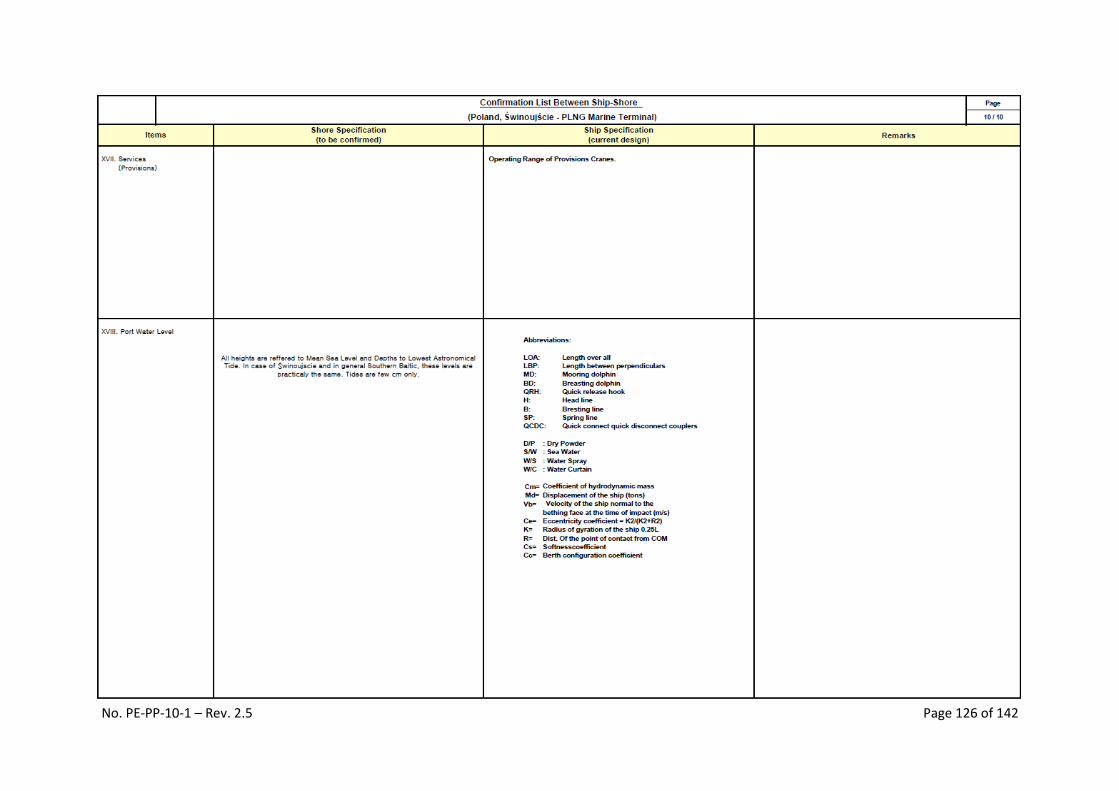
No. PE-PP-10-1 – Rev. 2.5 Page 126 of 142

No. PE-PP-10-1 – Rev. 2.5 Page 127 of 142

No. PE-PP-10-1 – Rev. 2.5 Page 128 of 142

No. PE-PP-10-1 – Rev. 2.5 Page 129 of 142

No. PE-PP-10-1 – Rev. 2.5 Page 130 of 142

No. PE-PP-10-1 – Rev. 2.5 Page 128 of 142
J.9 Appendix No. 9 – Unloading arms work range – PE-PP-10-1-Z-2

No. PE-PP-10-1 – Rev. 2.5 Page 132 of 143

No. PE-PP-10-1 – Rev. 2.5 Page 133 of 143
Possible configurations of the manifolds and the unloading arms

No. PE-PP-10-1 – Rev. 2.5 Page 134 of 143
J.10 Appendix No. 10 Quick release hook and fender – PE-PP-10-1-Z3

No. PE-PP-10-1 – Rev. 2.5 Page 135 of 143

No. PE-PP-10-1 – Rev. 2.5 Page 136 of 143
J.11 Appendix No. 11 – Schematics and parameters of the gangway tower and the
gangway, the range and SWL of the crane – PE-PP-10-1-W3
Gangway tower and gangway.
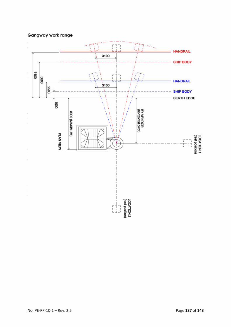
No. PE-PP-10-1 – Rev. 2.5 Page 137 of 143
Gangway work range

No. PE-PP-10-1 – Rev. 2.5 Page 138 of 143
Arms work range and crane lifting height
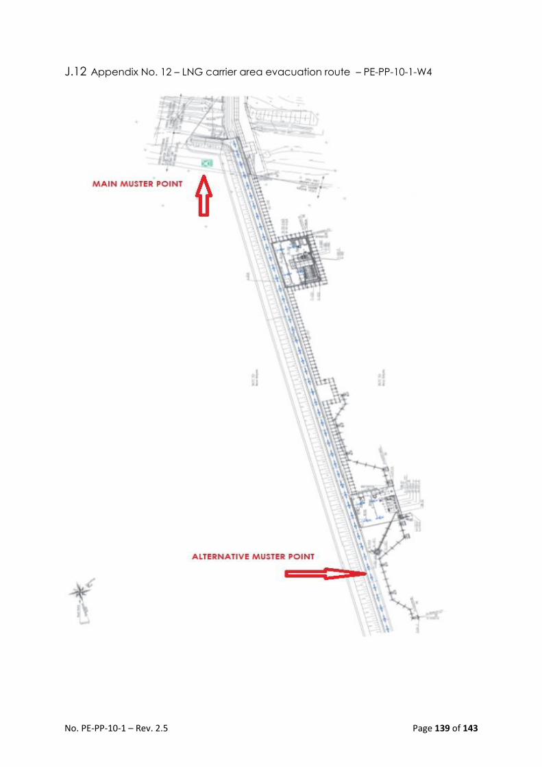
No. PE-PP-10-1 – Rev. 2.5 Page 139 of 143
J.12 Appendix No. 12 – LNG carrier area evacuation route – PE-PP-10-1-W4
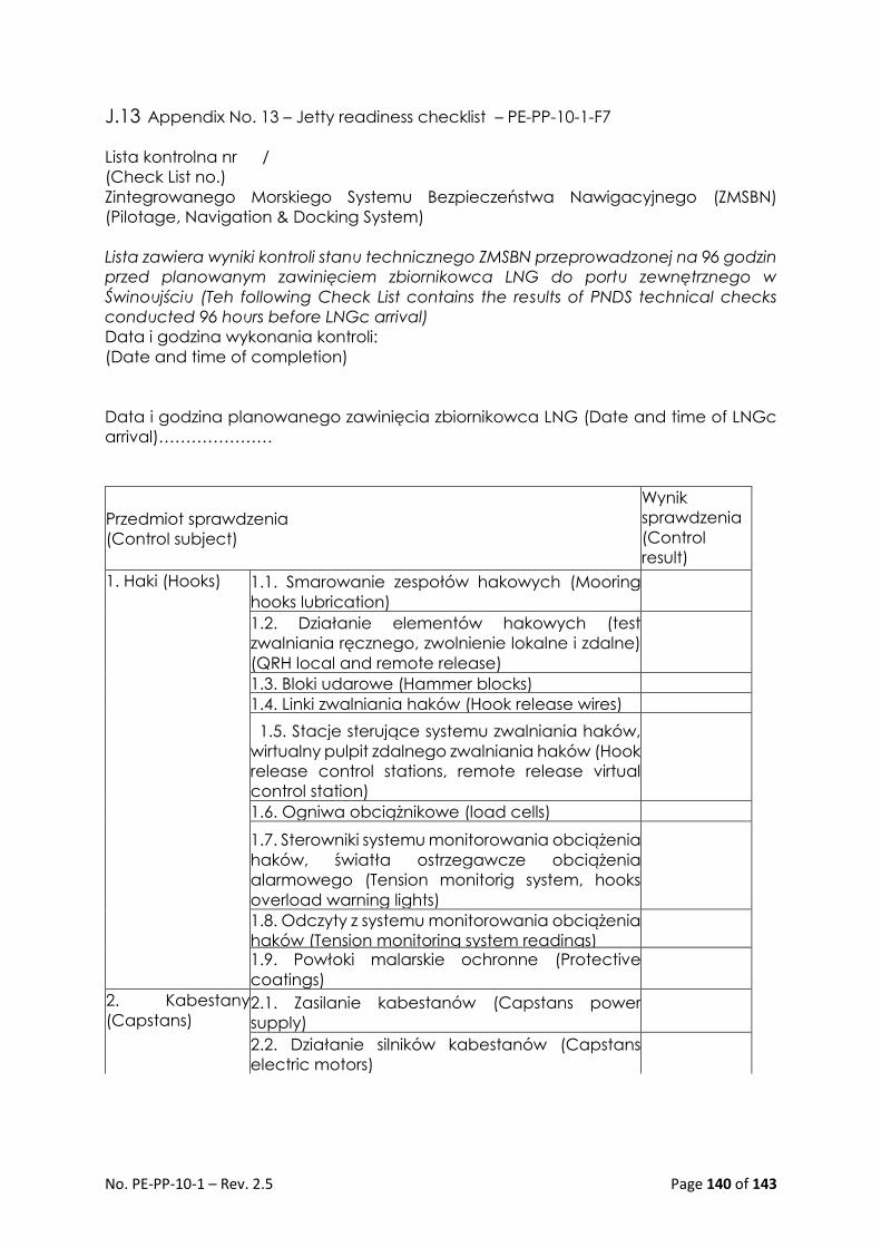
No. PE-PP-10-1 – Rev. 2.5 Page 140 of 143
J.13 Appendix No. 13 – Jetty readiness checklist – PE-PP-10-1-F7
Lista kontrolna nr /
(Check List no.)
Zintegrowanego Morskiego Systemu Bezpieczeństwa Nawigacyjnego (ZMSBN)
(Pilotage, Navigation & Docking System)
Lista zawiera wyniki kontroli stanu technicznego ZMSBN przeprowadzonej na 96 godzin
przed planowanym zawinięciem zbiornikowca LNG do portu zewnętrznego w
Świnoujściu (Teh following Check List contains the results of PNDS technical checks
conducted 96 hours before LNGc arrival)
Data i godzina wykonania kontroli:
(Date and time of completion)
Data i godzina planowanego zawinięcia zbiornikowca LNG (Date and time of LNGc
arrival)…………………
Przedmiot sprawdzenia
(Control subject)
Wynik
sprawdzenia
(Control
result)
1. Haki (Hooks)
1.1. Smarowanie zespołów hakowych (Mooring
hooks lubrication)
1.2. Działanie elementów hakowych (test
zwalniania ręcznego, zwolnienie lokalne i zdalne)
(QRH local and remote release)
1.3. Bloki udarowe (Hammer blocks)
1.4. Linki zwalniania haków (Hook release wires)
1.5. Stacje sterujące systemu zwalniania haków,
wirtualny pulpit zdalnego zwalniania haków (Hook
release control stations, remote release virtual
control station)
1.6. Ogniwa obciążnikowe (load cells)
1.7. Sterowniki systemu monitorowania obciążenia
haków, światła ostrzegawcze obciążenia
alarmowego (Tension monitorig system, hooks
overload warning lights)
1.8. Odczyty z systemu monitorowania obciążenia
haków (Tension monitoring system readings)
1.9. Powłoki malarskie ochronne (Protective
coatings)
2. Kabestany
(Capstans) 2.1. Zasilanie kabestanów (Capstans power
supply)
2.2. Działanie silników kabestanów (Capstans
electric motors)

No. PE-PP-10-1 – Rev. 2.5 Page 141 of 143
2.3. Zabezpieczenia przeciwprzeciążeniowe
(Overload protection)
2.4. Stan izolacji przewodów elektrycznych
(Electrical wires insulation)
2.5. Dławiki kablowe (Cable glands)
2.6. Obudowy układów sterowania (Control units
housing)
2.7. Hamulce kabestanów (Capstans brakes)
2.8. Obwody sterowania kabestanami
(przełączniki nożne, wybieraki kierunku, wyłączniki
awaryjne) (Capstans control circuts, direction
control, emergency stops)
2.9. Nagrzewnice antykondensacyjne (anti-
condensation heaters)
2.10. Desykant w obudowach kabestanów
(Dessicant in capstans housings)
2.11. Powłoki malarskie ochronne (Protective
coatings)
3. Tablica
wyświetlacza
(SmartDock
display)
3.1. Oczyszczenie tablicy wyświetlacza
(SmartDock display cleaning)
3.2. Test wyświetlacza (SmartDock display test)
3.3. Desykant w obudowie tablicy (Dessicant in
display housing)
3.4. Rotor elektryczny (Electical rotor)
4. Czujniki
podejścia statku
(Ship approach
sensors)
4.1. Oczyszczenie okienek obudów czujników
laserowych (Laser sensors windows cleaning )
4.2. Desykant w obudowach czujników
laserowych (Dessicant in laser sensors boxes)
4.3. Odczyty z systemu wspomagania dobijania
statku (SmartDock system readings)
5. Stacja
pogodowa
(Weather station)
5.1. Oczyszczenie czujnika stacji pogodowej
(Weather station sensor cleaning)
5.2. Odczyty ze stacji pogodowej (Weather station
readings)
6. Czujnik fali
(Wave sensor) 6.1. Desykant w obudowie czujnika fali (Dessicant
in wave sensor box)
6.2. Odczyty z czujnika fali (Wave sensor readings)
7. Czujnik prądów
morskich (Current
sensor)
7.1. Oczyszczenie czujnika prądów morskich
(Current sensor cleaning)
7.2. Odczyty z czujnika prądów morskich (Current
sensor readinigs)

No. PE-PP-10-1 – Rev. 2.5 Page 142 of 143
J.14 Appendix no. 14 – Hazardous zones around LNG carrier

No. PE-PP-10-1 – Rev. 2.5 Page 143 of 143
K. Literature.
1. OCIMF ISGOTT - International Safety Guide for Oil Tankers and Terminals – 5th
edition.
2. SIGTTO - Liquefied Gas Handling Principles on Ships and in Terminals - 3rd edition
(April 2000).
3. SIGTTO - LNG Operations in Port Areas (September 2003).
4. SIGTTO - Guide to Contingency Planning for Marine Terminals Handling
Liquefied Gases in Bulk-2nd edition (2001).
5. SIGTTO Training of Terminal Staff involved in Loading and Discharging Gas
Carrier (1996).
6. SIGTTO Jetty Maintenance and Inspection Guide (2008).
7. SIGTTO Ship Vetting and its Application to LNG (2004).
8. Liquefied Gas Fire Hazard Management - First Edition (2004)
9. OCIMF Marine Terminal Management and Self-Assessment (MTMSA).
10. OCIMF Marine Terminal Particulars Questionnaire (MTPQ).
11. OCIMF Marine Terminal Operator Competence & Training (MTOCT).
12. A Risk Based Approach for the Evaluation of Firefighting Equipment on Liquefied
Gas Jetties
13. Accident Prevention - The Use of Hoses and Hard-Arms at Marine Terminals
Handling Liquefied Gas - 2nd Edition
14. Contingency Planning and Crew Response Guide for Gas Carrier Damage at
Sea and in Port Approaches
15. Crew Safety Standards and Training for Large LNG Carriers
16. ESD Arrangements & Linked Ship/ Shore Systems for Liquefied Gas Carriers
17. Guide to Contingency Planning for Marine Terminals Handling Liquefied Gases
in Bulk
18. Guide to Contingency Planning for the Gas Carrier Alongside and Within Port
Limits, 2nd Ed
19. Guidelines for the Alleviation of Excessive Surge Pressures on ESD
20. Jetty Maintenance and Inspection Guide
21. Liquefied Gas Fire Hazard Management - First Edition
22. Liquefied Gas Handling Principles on Ships and in Terminals - 3rd edition
23. LNG Operations in Port Areas
24. LNG Shipping Suggested Competency Standards 2008 - Second Edition
25. LNG Transfer Arms and Manifold Draining, Purging and Disconnection
Procedure
26. Rapid Phase Transitions in LNG Carrier Manifold Drip Trays
27. Report on the Effects of Fire on LNG Carrier Containment Systems
28. Safe Havens for Disabled Gas Carriers
29. Sampling of Liquefied Gases - BSI Bulletin
30. Ship Vetting and its Application to LNG
31. Ship-Shore Compatibility Questionnaire
32. Site Selection and Design for LNG Ports and Jetties