lng research study · lng gas acceptability research study equipment selection criteria the legacy...
TRANSCRIPT

LNG Gas Acceptability Research Study
LNG Research Study
Half Size Gravity Vented Wall Furnace
December 2005
Prepared By:
The Southern California Gas Company
Engineering Analysis Center – Applied Technologies
Jorge Gutierrez
Firas Hamze
Carol Mak
Juan R. Mora

LNG Gas Acceptability Research Study
Acknowledgements The authors express appreciation to the following associates whose efforts contributed much to the success of this project.
Monica Clemens
David Kalohi
Johnny Lozano
Larry Sasadeusz
Rod Schwedler
Kevin Shea
Dale Tomlinson
Robert Munoz
Disclaimer LEGAL NOTICE
The Southern California Gas Company, its officers, employees, and contractors, make no warranty, expressed or implied, and assume no legal liability for accuracy of the information contained in this report; neither do they individually or collectively assume any liability with respect to the use of such information or report or for any damages which may result from the use of or reliance on any information, apparatus, methods, or process disclosed or described in or by this report.
No information contained in this report can be copied, reported, quoted, or cited in any way in publications, papers, brochures, advertising, or other publicly available documents without the prior written permission of the Southern California Gas Company.
Half Size Gravity Vented Wall Furnace Draft/Confidential – Do Not Cite i

LNG Gas Acceptability Research Study
Table of Contents Results Summary..............................................................................................................3
As Received Test ..........................................................................................................3 Rated Input Test (Tuned with Base Gas)......................................................................4 Rated Input Test (Tuned with Gas 8) ............................................................................5
Equipment Selection Criteria.............................................................................................6 Equipment Specification....................................................................................................6 Standards..........................................................................................................................6 Installation.........................................................................................................................6 Test Gases........................................................................................................................7 Test Procedure..................................................................................................................8
As Received Test (with Base Gas) ...............................................................................8 Rated Input Test (Tuned with Base Gas)......................................................................9 Rated Input Test (Tuned with Gas 8) ............................................................................9 Cold Ignition Test ........................................................................................................10 Hot Ignition Test ..........................................................................................................10
Results ............................................................................................................................11 As Received Test (with Base Gas) .............................................................................11
Input ........................................................................................................................11 Temperatures ..........................................................................................................12 Emissions ................................................................................................................13
Rated Input Test (Tuned with Base Gas)....................................................................14 Input ........................................................................................................................14 Temperatures ..........................................................................................................15 Emissions ................................................................................................................16
Rated Input Test (Tuned with Gas 8) ..........................................................................17 Input ........................................................................................................................17 Temperatures ..........................................................................................................18 Emissions ................................................................................................................19
Cold Ignition Test ........................................................................................................20
Half Size Gravity Vented Wall Furnace Draft/Confidential – Do Not Cite 1
Hot Ignition Test ..........................................................................................................21

LNG Gas Acceptability Research Study
Appendix A: Test Protocol...............................................................................................22
Appendix B: Tables of Averages.....................................................................................28 Appendix C: Test Gases .................................................................................................31 Appendix D: Zero, Span and Linearity Tables ................................................................32 Appendix E: Calculations ................................................................................................35 Appendix F: Test Equipment...........................................................................................40 Appendix G: Test Set-Up/Schematic ..............................................................................41 Appendix H: Half Size Wall Furnace Setup ....................................................................42
Half Size Gravity Vented Wall Furnace Draft/Confidential – Do Not Cite 2
LNG Gas Acceptability Research Study
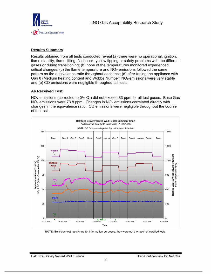
Half Size Gravity Vented Wall Heater Summary Chart As Received Test (with Base Gas) - 11/22/2005
0
30
60
90
120
150
180
1:05 PM 1:25 PM 1:45 PM 2:05 PM 2:25 PM 2:45 PM 3:05 PM 3:25 PM
Time
Equi
vale
nce
Rat
io X
100
( φ)
NO
X &
CO
(ppm
, Cor
rect
ed to
0%
O2)
0
300
600
900
1,200
1,500
1,800
Hea
ting
Valu
e &
Wob
be N
umbe
r (B
tu/c
f)St
ack
Tem
pera
ture
(°F)
Wobbe
NOX
φ
CO
Results Summary Results obtained from all tests conducted reveal (a) there were no operational, ignition, flame stability, flame lifting, flashback, yellow tipping or safety problems with the different gases or during transitioning; (b) none of the temperatures monitored experienced critical changes; (c) the flame temperature and NOX emissions followed the same pattern as the equivalence ratio throughout each test; (d) after tuning the appliance with Gas 8 (Medium heating content and Wobbe Number) NOX emissions were very stable and (e) CO emissions were negligible throughout all tests.
As Received Test NOX emissions (corrected to 0% O2) did not exceed 83 ppm for all test gases. Base Gas NOX emissions were 73.8 ppm. Changes in NOX emissions correlated directly with changes in the equivalence ratio. CO emissions were negligible throughout the course of the test.
Heating Value
Stack
Base Gas 3 Gas 6 Gas 7 Gas 4A BaseBase BaseGas 2 Gas 5A Gas 5 Gas 8 Gas 4
NOTE: CO Emissions stayed at 0 ppm throughout the test.
Half Size Gravity Vented Wall Furnace Draft/Confidential – Do Not Cite 3
NOTE: Emission test results are for information purposes, they were not the result of certified tests.

LNG Gas Acceptability Research Study
Half Size Gravity Vented Wall Heater Summary ChartRated Input Test (Tuned with Base Gas) - 12/06/2005
0
30
60
90
120
150
180
9:35 AM 9:55 AM 10:15 AM 10:35 AM 10:55 AM 11:15 AM 11:35 AM 11:55 AM 12:15 PM 12:35 PM 12:55 PM
Time
Equi
vale
nce
Rat
io X
100
( φ)
NO
X &
CO
(ppm
, Cor
rect
ed to
0%
O2)
0
300
600
900
1,200
1,500
1,800
Hea
ting
Valu
e &
Wob
be N
umbe
r (B
tu/c
f)St
ack
Tem
pera
ture
(°F)
Wobbe
NOXφ
CO
Rated Input Test (Tuned with Base Gas) When tuned with Base Gas, NOX emissions (corrected to 0% O2) were highest with Gas 7 (106 ppm) and Base Gas NOX emissions were 89 ppm. Changes in NOX emissions correlated directly with changes in the equivalence ratio. CO emissions values were negligible throughout the test.
Heating Value
Stack
Base Gas 3 Gas 6 Gas 7 Gas 4A BaseBase BaseGas 2 Gas 5A Gas 5 Gas 8 Gas 4
NOTE: CO Emissions stayed at 0 ppm throughout the test.
Half Size Gravity Vented Wall Furnace Draft/Confidential – Do Not Cite 4
NOTE: Emission test results are for information purposes, they were not the result of certified tests.

LNG Gas Acceptability Research Study
Half Size Gravity Vented Wall Heater Summary ChartRated Input Test (Tuned with Gas 8) - 12/07/2005
0
30
60
90
120
150
180
8:30 AM 8:50 AM 9:10 AM 9:30 AM 9:50 AM 10:10 AM 10:30 AM 10:50 AM 11:10 AM 11:30 AM 11:50 AM
Time
Equi
vale
nce
Rat
io X
100
( φ)
NO
X &
CO
(ppm
, Cor
rect
ed to
0%
O2)
0
300
600
900
1,200
1,500
1,800
Hea
ting
Valu
e &
Wob
be N
umbe
r (B
tu/c
f)St
ack
Tem
pera
ture
(°F)
Wobbe
NOX φ
CO
Rated Input Test (Tuned with Gas 8) When tuned with Gas 8, NOX emissions (corrected to 0% O2) decreased for all test gases compared to values obtained when the appliance was tuned with Base Gas. NOX emissions for Gas 7 were 97.9 ppm and 83.7 ppm for Base Gas; decreasing 7.7 ppm and 5.1 ppm from values obtained when the appliance was tuned with Base Gas. Changes in NOX emissions correlated directly with changes in the equivalence ratio. CO emissions values were negligible throughout the test.
Heating Value
Stack
Gas 8 Gas 3 Gas 6 Gas 7 Gas 4AGas 2 Gas 5A Gas 5 Base Gas 4Gas 8 Gas 8 Gas 8
NOTE: CO Emissions stayed at 0 ppm throughout the test.
Half Size Gravity Vented Wall Furnace Draft/Confidential – Do Not Cite 5
NOTE: Emission test results are for information purposes, they were not the result of certified tests.
LNG Gas Acceptability Research Study
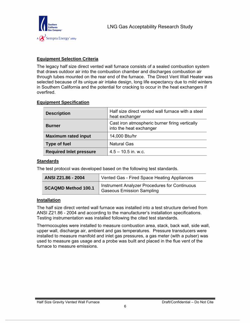
Equipment Selection Criteria The legacy half size direct vented wall furnace consists of a sealed combustion system that draws outdoor air into the combustion chamber and discharges combustion air through tubes mounted on the rear end of the furnace. The Direct Vent Wall Heater was selected because of its unique air intake design, long life expectancy due to mild winters in Southern California and the potential for cracking to occur in the heat exchangers if overfired.
Equipment Specification
Description Half size direct vented wall furnace with a steel heat exchanger
Burner Cast iron atmospheric burner firing vertically into the heat exchanger
Maximum rated input 14,000 Btu/hr
Type of fuel Natural Gas
Required Inlet pressure 4.5 – 10.5 in. w.c. Standards The test protocol was developed based on the following test standards.
ANSI Z21.86 - 2004 Vented Gas - Fired Space Heating Appliances
SCAQMD Method 100.1 Instrument Analyzer Procedures for Continuous Gaseous Emission Sampling
Installation The half size direct vented wall furnace was installed into a test structure derived from ANSI Z21.86 - 2004 and according to the manufacturer’s installation specifications. Testing instrumentation was installed following the cited test standards.
Half Size Gravity Vented Wall Furnace Draft/Confidential – Do Not Cite 6
Thermocouples were installed to measure combustion area, stack, back wall, side wall, upper wall, discharge air, ambient and gas temperatures. Pressure transducers were installed to measure manifold and inlet gas pressures, a gas meter (with a pulser) was used to measure gas usage and a probe was built and placed in the flue vent of the furnace to measure emissions.

LNG Gas Acceptability Research Study
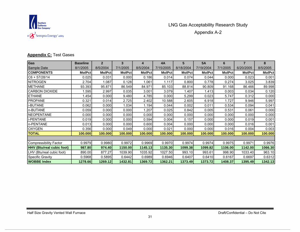
Test Gases The following gases have been specifically formulated to cover the range, compositions and calorific values of natural gases that could be delivered in the Southern California Gas Company territory by current natural gas suppliers and future LNG suppliers. Composition details are specified in Appendix C.
Gas Wobbe Number (Btu/cf) Heating Value (Btu/cf)
Base 1,278 (Low Wobbe) 987 (Low heat content)
2 1,269 (Lowest Wobbe) 974 (Lowest heat content)
3 1,433 (Highest Wobbe) 1,150 (Highest heat content)
4 1,370 (Medium Wobbe) 1,145 (High heat content)
4A 1,362 (Medium Wobbe) 1,135 (High heat content)
5 1,374 (Medium Wobbe) 1,100 (High heat content)
5A 1,362 (Medium Wobbe) 1,100 (High heat content)
6 1,408 (High Wobbe) 1,106 (High heat content)
7 1,395 (High Wobbe) 1,142 (High heat content)
8 1,342 (Medium Wobbe) 1,066 (Medium heat content)
Half Size Gravity Vented Wall Furnace Draft/Confidential – Do Not Cite 7
LNG Gas Acceptability Research Study
Test Procedure Test procedures were developed based on the above test standards. However, due to differences between test standards, time limitations, and facility restrictions, the test procedures were simplified. Test procedure simplification was done with input from manufacturers and consultants in the context of developing and maintaining a sound test procedure.
Before every test, the following steps were performed:
All emissions analyzers were calibrated and linearity was checked. Data loggers were checked and temperatures, pressures, and gas flow readings
were verified. During every test, the following steps were performed:
Base Gas and Test Gases were run continuously with switching between gases taking less than 14 seconds.
Emissions, pressures, temperatures and combustion stability were monitored, during and after changeover.
After every test, the following steps were performed:
Flue vent was inspected for soot formation. Test data was downloaded. Linearity and drift inspections were performed on all emissions analyzers.
As Received Test (with Base Gas) Using Base Gas, the wall furnace was lit to allow the appliance to warm-up, the manifold pressure was examined and the input rate was found to be 9,373 Btu/hr, which is 33.1% below rated input. Once readings were stable, data collection was started and the gases were run in the following order:
Base Gas for 10 minutes. Gas 3 for 10 minutes. Gas 6 for 10 minutes. Gas 7 for 10 minutes. Reestablish Base Gas for 10 minutes. Gas 2 for 10 minutes. Gas 5A for 10 minutes. Gas 5 for 10 minutes. Reestablish Base Gas for 10 minutes. Gas 8 for 10 minutes. Gas 4A for 10 minutes. Gas 4 for 10 minutes.
Half Size Gravity Vented Wall Furnace Draft/Confidential – Do Not Cite 8
Conclude testing with Base Gas for 10 minutes.
LNG Gas Acceptability Research Study
Rated Input Test (Tuned with Base Gas) Using Base Gas, the manifold and inlet pressures were adjusted and an input rate of 11,017 Btu/hr was achieved; which is 21.3% below rated input. Once readings were stable, data collection was started and the gases were run in the following order:
Base Gas for 15 minutes. Gas 3 for 15 minutes. Gas 6 for 15 minutes. Gas 7 for 15 minutes. Reestablish Base Gas for 15 minutes. Gas 2 for 15 minutes. Gas 5A for 15 minutes. Gas 5 for 15 minutes. Reestablish Base Gas for 10 minutes. Gas 8 for 15 minutes. Gas 4A for 15 minutes. Gas 4 for 15 minutes. Conclude testing with Base Gas for 15 minutes.
Rated Input Test (Tuned with Gas 8) Using Gas 8, the manifold was adjusted to achieve a similar input rate and performance (including emissions, temperatures, etc.) as with Base Gas. Once readings were stable, data collection was started and the gases were run in the following order:
Gas 8 for 15 minutes. Gas 3 for 15 minutes. Gas 6 for 15 minutes. Gas 7 for 15 minutes. Reestablish Gas 8 for 15 minutes. Gas 2 for 15 minutes. Gas 5A for 15 minutes. Gas 5 for 15 minutes. Reestablish Gas 8 for 15 minutes. Base Gas for 15 minutes. Gas 4A for 15 minutes. Gas 4 for 15 minutes.
Half Size Gravity Vented Wall Furnace Draft/Confidential – Do Not Cite 9
Conclude testing with Gas 8 for 15 minutes.

LNG Gas Acceptability Research Study
Cold Ignition Test The unit was tuned with each test gas. With appliance’s components at ambient temperature, three ignition tests were conducted following the protocol detailed §7.1 & §7.2 of Appendix A.
Hot Ignition Test
Half Size Gravity Vented Wall Furnace Draft/Confidential – Do Not Cite 10
The unit was tuned with each test gas. After steady-state operating conditions were achieved, three ignition tests were conducted following the protocol detailed in §7.3 & §7.4 of Appendix A.

LNG Gas Acceptability Research Study
Half Size Gravity Vented Wall Heater Input ChartAs Received Test (with Base Gas) - 11/22/2005
0
5
10
15
20
25
30
1:05 PM 1:25 PM 1:45 PM 2:05 PM 2:25 PM 2:45 PM 3:05 PM 3:25 PM
Time
Inle
t & M
anifo
ld P
ress
ure
(in. w
.c.)
Inpu
t Rat
e (M
Btu
/hr)
& C
orre
cted
Gas
Flo
w (s
cfh)
0
300
600
900
1,200
1,500
1,800
Hea
ting
Valu
e &
Wob
be N
umbe
r (B
tu/c
f)
Manifold
Wobbe
Results1,2,3
As Received Test (with Base Gas)
Input
The input rate corresponds with changes in Wobbe Number, with the minimum and maximum input rates being 9,225 Btu/hr (Base Gas) and 11,026 Btu/hr (Gas 3). The corrected gas flow ranged from 8.9 scfh to 9.4 scfh. Inlet and manifold pressures remained stable during the course of the test.
There were not drops in inlet pressure at the beginning of each gas run because we didn’t to purge the gas supply hose before the gas meter.
Heating Value
Inlet
InputRateCorrected
Gas Flow
Base Gas 3 Gas 6 Gas 7 Gas 4A BaseBase BaseGas 2 Gas 5A Gas 5 Gas 8 Gas 4
1 All emissions, temperature and input values mentioned throughout the results section are average values. 2 Emissions values are corrected to 0% O2.
Half Size Gravity Vented Wall Furnace Draft/Confidential – Do Not Cite 11
3 When either Base Gas or Gas 8 is used as the set-up gas, the values reported for the set-up gas are the average values of all runs for that gas during each test.

LNG Gas Acceptability Research Study
Half Size Gravity Vented Wall Heater Temperature ChartAs Received Test (with Base Gas) - 11/22/2005
0
30
60
90
120
150
180
1:05 PM 1:25 PM 1:45 PM 2:05 PM 2:25 PM 2:45 PM 3:05 PM 3:25 PM
Time
Am
bien
t, G
as, D
isch
arge
d A
ir, B
ack
Wal
l,Si
de W
all &
Top
Wal
l Tem
pera
ture
(°F)
0
350
700
1,050
1,400
1,750
2,100
Fire
Box
, Fla
me
& S
tack
Tem
pera
ture
(°F)
Flame
Upper Wall
Gas
Back Wall
Stack
Fire Box
SideWall
Temperatures
The highest flame temperature was observed with Gas 7 at 1,505°F then remained below 1,485°F for the rest of the gases tested. The back wall temperatures ranged between 121°F and 130°F, fire box temperature ranged between 480°F and 499°F and discharge air temperature remained below 101°F. Stack temperatures remained stable throughout the test and reached a high of 353.2°F with Gas 4A. Ambient and gas temperatures were stable at 77.0 ± 3.0°F.
Ambient
Discharged Air
Base Gas 3 Gas 6 Gas 7 Gas 4A BaseBase BaseGas 2 Gas 5A Gas 5 Gas 8 Gas 4
Half Size Gravity Vented Wall Furnace Draft/Confidential – Do Not Cite 12
The interruptions in discharge air temperature during Gas 5 and part of the Base Gas run was caused by a loose thermocouple wire connection.

LNG Gas Acceptability Research Study
Half Size Gravity Vented Wall Heater Emissions ChartAs Received Test (with Base Gas) - 11/22/2005
0
4
8
12
16
20
24
1:05 PM 1:25 PM 1:45 PM 2:05 PM 2:25 PM 2:45 PM 3:05 PM 3:25 PM
Time
O2 &
CO
2 (%
)H
C &
CO
(ppm
, Cor
rect
ed to
0%
O2)
0
20
40
60
80
100
120
NO
X (p
pm, C
orre
cted
to 0
% O
2)
Base Gas 3 Gas 6 Gas 7 Gas 4A
HC
NOTE: CO Emissions stayed at 0 ppm throughout the test.
O2
NOX
CO2
BaseBase BaseGas 2 Gas 5A Gas 5 Gas 8 Gas 4
CO
Emissions
NOX emissions ranged from 72.4 ppm (Gas 2) to 83.0 ppm (Gas 7). Base Gas NOX emissions were 73.8 ppm. CO2 percentage and NOX emissions curves followed the same pattern throughout the test; which was inversely proportional to the O2 percentage curve. CO emissions remained at 0 ppm and HC emissions stayed below 1.3 ppm throughout the course of the test.
Half Size Gravity Vented Wall Furnace Draft/Confidential – Do Not Cite 13
NOTE: Emission test results are for information purposes, they were not the result of certified tests.

LNG Gas Acceptability Research Study
Half Size Gravity Vented Wall Heater Input ChartRated Input Test (Tuned with Base Gas) - 12/06/2005
0
5
10
15
20
25
30
9:35 AM 9:55 AM 10:15 AM 10:35 AM 10:55 AM 11:15 AM 11:35 AM 11:55 AM 12:15 PM 12:35 PM 12:55 PM
Time
Inle
t & M
anifo
ld P
ress
ure
(in. w
.c.)
Inpu
t Rat
e (M
Btu
/hr)
& C
orre
cted
Gas
Flo
w (s
cfh)
0
300
600
900
1,200
1,500
1,800
Hea
ting
Valu
e &
Wob
be N
umbe
r (B
tu/c
f)Manifold
Wobbe
Rated Input Test (Tuned with Base Gas)
Input
The highest input rate was observed with Gas 3 (12,440 Btu/hr) and the lowest with Gas 2 (10,760 Btu/hr). Corrected gas flow rates ranged from 10.5 scfh (Gas 4A) to 11.0 scfh (Gas 2). Manifold and inlet pressures were within tolerances specified in the test protocol.
Heating Value
Inlet
InputRate
Corrected Gas Flow
Base Gas 3 Gas 6 Gas 7 Gas 4A BaseBase BaseGas 2 Gas 5A Gas 5 Gas 8 Gas 4
Half Size Gravity Vented Wall Furnace Draft/Confidential – Do Not Cite 14
The drops in inlet pressure at the beginning of each gas run were the result of purging the gas supply hose before the gas meter.

LNG Gas Acceptability Research Study
Half Size Gravity Vented Wall Heater Temperature ChartRated Input Test (Tuned with Base Gas) - 12/06/2005
0
30
60
90
120
150
180
9:35 AM 9:55 AM 10:15 AM 10:35 AM 10:55 AM 11:15 AM 11:35 AM 11:55 AM 12:15 PM 12:35 PM 12:55 PM
Time
Am
bien
t, G
as, B
ack
Wal
l,Si
de W
all &
Top
Wal
l Tem
pera
ture
(°F)
0
350
700
1,050
1,400
1,750
2,100
Dis
char
ged
Air,
Fla
me
& S
tack
Tem
pera
ture
(°F)Flame
Upper Wall
Gas
Back Wall
Stack
SideWall
Temperatures
Ambient
Discharged Air
Base Gas 3 Gas 6 Gas 7 Gas 4A BaseBase BaseGas 2 Gas 5A Gas 5 Gas 8 Gas 4
Half Size Gravity Vented Wall Furnace Draft/Confidential – Do Not Cite 15
The highest flame temperature was observed with Gas 6 (1,638°F), whereas Gas 2 (1,531°F) had the lowest flame temperature. Stack temperature was highest with Gas 6 (362.5°F) while the lowest was observed with Gas 2 (354.5°F). Back wall temperature ranged from 117.9°F to 130.7°F and discharged air temperature ranged from 87.6°F to 93.9°F. Ambient, gas and side wall temperatures were steady throughout of the course of the test.

LNG Gas Acceptability Research Study
Half Size Gravity Vented Wall Heater Emissions ChartRated Input Test (Tuned with Base Gas) - 12/06/2005
0
4
8
12
16
20
24
9:35 AM 9:55 AM 10:15 AM 10:35 AM 10:55 AM 11:15 AM 11:35 AM 11:55 AM 12:15 PM 12:35 PM 12:55 PM
Time
O2 &
CO
2 (%
)H
C &
CO
(ppm
, Cor
rect
ed to
0%
O2)
0
20
40
60
80
100
120
NO
X (p
pm, C
orre
cted
to 0
% O
2)
Base Gas 3 Gas 6 Gas 7 Gas 4A
HC
NOTE: CO Emissions stayed at 0 ppm throughout the test.
O2
NOX
CO2
BaseBase BaseGas 2 Gas 5A Gas 5 Gas 8 Gas 4
Emissions
NOX emissions were highest with Gas 7 (105.6 ppm) and lowest with and Gas 2 (86.2 ppm). Base Gas NOX emissions were at 88.8 ppm. CO2 percentage and NOX emissions followed the same pattern throughout the test; which was inversely proportional to the O2 percentage. The HC emission remained below 1 ppm and CO emissions were negligible throughout the course of the test.
Half Size Gravity Vented Wall Furnace Draft/Confidential – Do Not Cite 16
NOTE: Emission test results are for information purposes, they were not the result of certified tests.

LNG Gas Acceptability Research Study
Half Size Gravity Vented Wall Heater Input ChartRated Input Test (Tuned with Gas 8) - 12/07/2005
0
5
10
15
20
25
30
8:30 AM 8:50 AM 9:10 AM 9:30 AM 9:50 AM 10:10 AM 10:30 AM 10:50 AM 11:10 AM 11:30 AM 11:50 AM
Time
Inle
t & M
anifo
ld P
ress
ure
(in. w
.c.)
Inpu
t Rat
e (M
Btu
/hr)
& C
orre
cted
Gas
Flo
w (s
cfh)
0
300
600
900
1,200
1,500
1,800
Hea
ting
Valu
e &
Wob
be N
umbe
r (B
tu/c
f)
Manifold
Wobbe
Rated Input Test (Tuned with Gas 8)
Input
The highest input rate was observed with Gas 3 (13,365 Btu/hr) and the lowest with Gas 2 (11,519 Btu/hr). Corrected gas flow rates had little variance, ranging from 11.3 scfh (Gas 4A) to 11.8 scfh (Gas 2 and Base Gas). The manifold and inlet pressure remained stable throughout the course of the test.
Heating Value
Inlet
InputRate
Corrected Gas Flow
Gas 3 Gas 6 Gas 7 Gas 4AGas 2 Gas 5A Gas 5 Base Gas 4Gas 8 Gas 8 Gas 8 Gas 8
Half Size Gravity Vented Wall Furnace Draft/Confidential – Do Not Cite 17
The drops in inlet pressure at the beginning of each gas run were the result of purging the gas supply hose before the gas meter.

LNG Gas Acceptability Research Study
Half Size Gravity Vented Wall Heater Temperature ChartRated Input Test (Tuned with Gas 8) - 12/07/2005
0
30
60
90
120
150
180
8:30 AM 8:50 AM 9:10 AM 9:30 AM 9:50 AM 10:10 AM 10:30 AM 10:50 AM 11:10 AM 11:30 AM 11:50 AM
Time
Am
bien
t, G
as, B
ack
Wal
l,Si
de W
all &
Top
Wal
l Tem
pera
ture
(°F)
0
350
700
1,050
1,400
1,750
2,100
Flam
e, d
isch
arge
Air
& S
tack
Tem
pera
ture
(°F)Flame
Upper Wall
Gas
Back Wall
Stack
SideWall
Temperatures
Ambient
Discharge Air
Gas 3 Gas 6 Gas 7 Gas 4AGas 2 Gas 5A Gas 5 Base Gas 4Gas 8 Gas 8 Gas 8 Gas 8
Half Size Gravity Vented Wall Furnace Draft/Confidential – Do Not Cite 18
The flame temperature was highest with Gas 3 (1,545°F) and lowest with Base Gas and Gas 2 (1,450°F and 1,451°F, respectively). The back wall temperatures were 127.0 ± 4.0°F, stack temperatures were 364.0 ± 3.0°F and discharge air remained stable at 94.0 ± 5.0°F. Ambient and gas temperatures increased slightly as the test progressed but were stable at 74.0 ± 2.0°F.
LNG Gas Acceptability Research Study
Half Size Gravity Vented Wall Heater Emissions ChartRated Input Test (Tuned with Gas 8) - 12/07/2005
0
4
8
12
16
20
24
8:30 AM 8:50 AM 9:10 AM 9:30 AM 9:50 AM 10:10 AM 10:30 AM 10:50 AM 11:10 AM 11:30 AM 11:50 AM
Time
O2 &
CO
2 (%
)H
C &
CO
(ppm
, Cor
rect
ed to
0%
O2)
0
20
40
60
80
100
120
NO
X (p
pm, C
orre
cted
to 0
% O
2)
Gas 3 Gas 6 Gas 7 Gas 4A
HC
NOTE: CO Emissions stayed at 0 ppm throughout the test.
O2
NOX
CO2
Gas 2 Gas 5A Gas 5 Base Gas 4Gas 8 Gas 8 Gas 8 Gas 8
Emissions
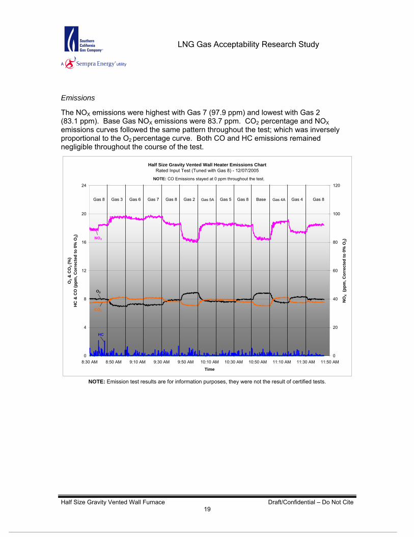
The NOX emissions were highest with Gas 7 (97.9 ppm) and lowest with Gas 2 (83.1 ppm). Base Gas NOX emissions were 83.7 ppm. CO2 percentage and NOX emissions curves followed the same pattern throughout the test; which was inversely proportional to the O2 percentage curve. Both CO and HC emissions remained negligible throughout the course of the test.
Half Size Gravity Vented Wall Furnace Draft/Confidential – Do Not Cite 19
NOTE: Emission test results are for information purposes, they were not the result of certified tests.
LNG Gas Acceptability Research Study
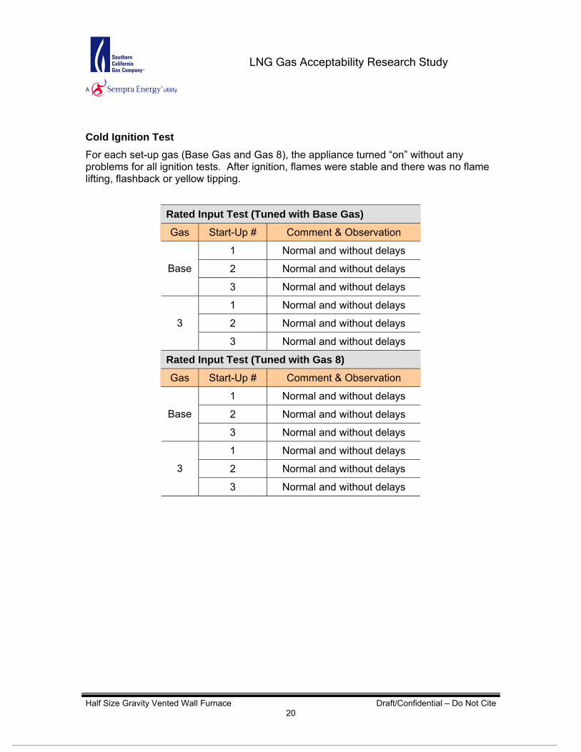
Cold Ignition Test For each set-up gas (Base Gas and Gas 8), the appliance turned “on” without any problems for all ignition tests. After ignition, flames were stable and there was no flame lifting, flashback or yellow tipping.
Half Size Gravity Vented Wall Furnace Draft/Confidential – Do Not Cite 20
Rated Input Test (Tuned with Base Gas)
Gas Start-Up # Comment & Observation
1 Normal and without delays
2 Normal and without delays Base
3 Normal and without delays
1 Normal and without delays
2 Normal and without delays 3
3 Normal and without delays
Rated Input Test (Tuned with Gas 8)
Gas Start-Up # Comment & Observation
1 Normal and without delays
2 Normal and without delays Base
3 Normal and without delays
1 Normal and without delays
2 Normal and without delays 3
3 Normal and without delays

LNG Gas Acceptability Research Study
Hot Ignition Test For each set-up gas (Base Gas and Gas 8), the appliance turned “on” without any problems for all ignition tests. After ignition, flames were stable and there was no flame lifting, flashback or yellow tipping.
Half Size Gravity Vented Wall Furnace Draft/Confidential – Do Not Cite 21
Rated Input Test (Tuned with Base Gas)
Gas Start-Up # Comment & Observation
1 Normal and without delays
2 Normal and without delays Base
3 Normal and without delays
1 Normal and without delays
2 Normal and without delays 3
3 Normal and without delays
Rated Input Test (Tuned with Gas 8)
Gas Start-Up # Comment & Observation
1 Normal and without delays
2 Normal and without delays Base
3 Normal and without delays
1 Normal and without delays
2 Normal and without delays 3
3 Normal and without delays

LNG Gas Acceptability Research Study
Half Size Gravity Vented Wall Furnace Draft/Confidential – Do Not Cite 22
Appendix A: Test Protocol
1. Standards
The test protocol for this appliance is based on the following test standards:
ANSI Z21.86 - 2004 Vented Gas - Fired Space Heating Appliances
SCAQMD Method 100.1 Instrument Analyzer Procedures for Continuous Gaseous Emission Sampling
2. Equipment Description
Description Half Size Direct Vented Wall Furnace with a steel heat exchanger
Burner Cast iron atmospheric burner firing vertically into the heat exchanger
Maximum rated input 14,000 Btu/hr
Type of fuel Natural Gas
Required inlet pressure 4.5 – 10.5 in. w.c.
3. Test Arrangement
3.1. Basic Setup A test wall should be built as specified on Figure 6 of ANSI Z21.86 - 2004. The wall furnace shall be installed on the test wall as per the manufacturer’s installation manual with minimum clearances of 5 inches to the adjacent side wall, 11 inches to the ceiling, and 1 ¾ inches to the floor.
3.2. Vent Pipe The wall furnace vent pipe provided with the unit by the manufacturer is to be used. The emissions sample probe and three-point thermocouple grid (wired as a thermopile) must be constructed per SCAQMD Protocol.
3.3. Testing Instrumentation Instrumentation must adhere as close as possible to the SCAQMD Method 100.1.
3.4. Temperatures and Pressures Provide instrumentation to measure ambient, fuel (natural gas), wall, stack and discharge air temperatures. In addition, also provide instrumentation to measure inlet and manifold pressures. Provide thermocouples in other locations as appropriate to record possible effects of gas blend changes. If possible, seek assistance from the manufacturer in selecting additional thermocouple locations.
LNG Gas Acceptability Research Study
Half Size Gravity Vented Wall Furnace Draft/Confidential – Do Not Cite 23
3.5. Special Measures - Windows & camera access Cover pilot opening with a clear high temperature plastic material and utilize as a window to view the flame. Additional window or camera access will not be made because the gasket for the combustion area contains Asbestos.
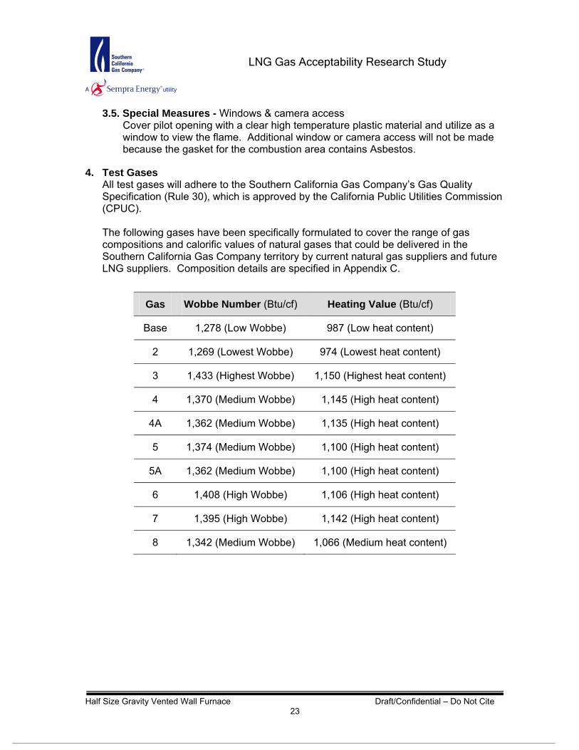
4. Test Gases All test gases will adhere to the Southern California Gas Company’s Gas Quality Specification (Rule 30), which is approved by the California Public Utilities Commission (CPUC). The following gases have been specifically formulated to cover the range of gas compositions and calorific values of natural gases that could be delivered in the Southern California Gas Company territory by current natural gas suppliers and future LNG suppliers. Composition details are specified in Appendix C.
Gas Wobbe Number (Btu/cf) Heating Value (Btu/cf)
Base 1,278 (Low Wobbe) 987 (Low heat content)
2 1,269 (Lowest Wobbe) 974 (Lowest heat content)
3 1,433 (Highest Wobbe) 1,150 (Highest heat content)
4 1,370 (Medium Wobbe) 1,145 (High heat content)
4A 1,362 (Medium Wobbe) 1,135 (High heat content)
5 1,374 (Medium Wobbe) 1,100 (High heat content)
5A 1,362 (Medium Wobbe) 1,100 (High heat content)
6 1,408 (High Wobbe) 1,106 (High heat content)
7 1,395 (High Wobbe) 1,142 (High heat content)
8 1,342 (Medium Wobbe) 1,066 (Medium heat content)
LNG Gas Acceptability Research Study
Half Size Gravity Vented Wall Furnace Draft/Confidential – Do Not Cite 24
5. Basic Operating Condition Unless required otherwise by specific test requirements, the following are to apply:
5.1. Room temperature Room temperature shall be maintained between 65 - 85°F. The temperature shall be determined by means of 4 J-Type thermocouples, the junctions of which are shielded from radiation. These thermocouple junctions shall be located so room air temperature can be measured at points approximately 24 inches away from the approximate midpoints of each of the 4 sides of the appliance or test enclosure. The thermocouple leads shall be connected to a data logger, and room temperature shall be the average of the four individual temperature readings.
5.2. Test Pressures and Burner Adjustments Unless otherwise stated, all tests will be conducted at normal inlet test pressure and normal input rate. Burner adjustments shall only be made after the appliance has been operated for 15 minutes from a cold start (i.e. all parts of the appliance are at room temperature) to verify the input rating. The burner input must be within ± 2% of the appliance’s rated input. Primary air shall be set to give a good flame at this adjustment and neither burner ratings nor primary air adjustments shall be changed during a series of tests with any one test gas. Any adjustments resulting in an appreciable deposit of carbon during any of the tests specified shall not be acceptable.
5.3. Burner Operating Characteristics Main burners and ignition devices shall be effectively ignited without delayed ignition or flashback when turned on and off at received and/or maximum allowable input rate and inlet test pressure, either manually or by a thermostatically actuated control device. When ignition is made, the flames shall not flash outside the appliance. The burners should ignite, operate and extinguish without any undue noise.
5.4. Pilot Burners and Safety Shutoff Devices The pilot shall not deposit appreciable carbon during any test specified when adjusted according to the manufacturer’s instructions. The pilot shall effect ignition of gas at the main burner port(s) (except for designed turn-off of intermittent or interrupted pilots) and shall not become extinguished and remain extinguished when the gas to the main burner(s) is turned off and on in a normal manner. The test shall be conducted for each type of gas using the following method of test: Gas shall be admitted to the main burner(s) by turning on fully in a continuous movement any manual means provided for controlling main burner gas flow. At least 3 successive ignition tests shall be conducted with the main burner gas flow maintained for 30 seconds and interrupted for 30 seconds for each cycle.

LNG Gas Acceptability Research Study
Half Size Gravity Vented Wall Furnace Draft/Confidential – Do Not Cite 25
Failure to affect ignition immediately after gas reaches the main burner port(s) in any one instance, or continued extinction of the pilot, shall be considered as noncompliance with this provision (Note: Test the unit with Gases 2 and 3 first. If it failed, retest with Gases 4A and 6). Any type of pilot equipped with an automatic igniter shall not cause excessive flame flash out or damage to the appliance.
5.5. Wall, Floor and Ceiling Temperatures The temperatures on the surface of any exterior portion of the test walls and ceiling structures in contact with the wall furnace shall not be more than 117°F in excess of room temperature when the appliance is operated as required in the following test method. The temperatures of the back wall of the appliance, the test vent, on the floor under the appliance and for a distance of 18 inches in front of and to the sides of the appliance shall not be more than 90°F in excess of room temperature when the appliance is operated as required in the following method of test.
5.6. Flue Gas temperature Under normal operating conditions, the average flue gas temperature of the wall furnace shall not exceed 380°F above room temperature. The flue gas temperature shall be determined by a grid of parallel-connected No. 24 AWG thermocouples, located at the flue outlet and connected to a data logger.
5.7. Temperature at Discharge Air Opening and Surface Temperature Testing shall be conducted as specified in §8.7.1 of ANSI Z21.86 - 2004.
5.8. Flame Temperature Due to the difficulties and cost involved in accurately measuring flame temperature continuously during each test, a simplistic method for measuring flame temperature will be used. This method requires the installation of a thermocouple tip inside the outer mantel of the flame such that it is fixed throughout the length of the test. Due to measurement method and changes in both flame shape and flame length, readings simply indicate temperature treads in the flame zone.
6. Testing
6.1. As Received Test Operate the wall furnace with Base Gas as received (i.e. with furnace gas regulator and manifold pressure as set by manufacturer/vender). Also, begin collecting temperature, pressure and emissions data while verifying proper operation of all equipment and instrumentation. Continue steady furnace operation with Base Gas for a specified duration and conduct a high-speed switch to the first test gas. Record data before, during and after changeover and observe transient phenomena. Possible phenomena include flame flashback, noise, instability or outage, etc. (NOTE: The furnace firing rate is not to be adjusted).

LNG Gas Acceptability Research Study
Half Size Gravity Vented Wall Furnace Draft/Confidential – Do Not Cite 26
With the furnace continuing to operate at steady state on the first test gas, conduct a high-speed switch to another test gas and record observations and data. Conduct a high-speed switch to the Base Gas and record observations and data as indicated above. Continue testing by reestablishing steady state conditions with the Base Gas after two or three runs with test gases. When testing has been conducted with all gases, shut down the furnace and examine flue collector and vent connection area for presence of soot by means of the swab technique. If soot is found, clean surfaces and repeat testing with suspect gas blend(s), selected on the basis of earlier yellow tipping observations. Establish which gas deposited soot in the appliance.
6.2. Rated Input (Tuned with Base Gas) Tune the appliance with Base Gas to the maximum achievable input rate. Follow the same procedures as specified in the As Received Test above. If it is discovered during the As Received Test that the appliance is operating at rated input, then the As Received Test becomes the Rated Input Test.
6.3. Rated Input (Tuned with Gas 8) Tune the appliance with Gas 8 to achieve the same input rate and similar performance as with Base Gas. Follow the same procedures as specified in the As Received Test.
7. Ignition Tests Shortly after and during ignition, observe flames and note yellow tipping, flame lifting, flashback phenomena or lack of same.
7.1. Cold Ignition Test (Tuned with Base Gas) With the appliance at room temperature and at the maximum achievable input rate observed during initial tuning with Base Gas, purge the gas delivery system with Base Gas. Using Base Gas, turn the appliance “ON” and document any combustion, ignition or flame irregularities. Allow the appliance to cool down to room temperature then repeat this procedure 2 more times. Purge the gas delivery system with Gas 3. Using Gas 3, turn the appliance “ON” and document any combustion, ignition or flame irregularities. Allow the appliance to cool down to room temperature then repeat this procedure 2 more times.
7.2. Cold Ignition Test (Tuned with Gas 8) Follow the same procedure as Cold Ignition Test (Tuned w/ Base Gas) but substitute Base Gas with Gas 8.

LNG Gas Acceptability Research Study
Half Size Gravity Vented Wall Furnace Draft/Confidential – Do Not Cite 27
7.3. Hot Ignition Test (Tuned with Base Gas) With the appliance at steady state temperatures and at the maximum achievable input rate observed during initial tuning with Base Gas, purge the gas delivery system with Base Gas. Using Base Gas, turn the appliance “ON” and document any combustion, ignition or flame irregularities. Repeat this procedure 2 more times without allowing the appliance to cold down. Purge the gas delivery system with Gas 3. Using Gas 3, turn the appliance “ON” and document any combustion, ignition or flame irregularities. Repeat this procedure 2 more times without allowing the appliance to cool down.
7.4. Hot Ignition Test (Tuned with Gas 8) Follow the same procedure as Cold Ignition Test (Tuned w/ Base Gas) but substitute Base Gas with Gas 8.
8. Special tests Special tests may be conducted to investigate phenomena of concern to the furnace manufacturer. The decision of whether or not to test and the design of appropriate tests will be discussed with the manufacturer.
9. Additional Testing Conduct additional testing and/or testing with other gas blends, per the Phase II protocol, when test results or observations indicate it is necessary. If indicated additional testing is outside of the project scope, include appropriate comment in the test report.

LNG Gas Acceptability Research Study
Appendix A-2
Appendix B: Tables of Averages
As Received Test (with Base Gas)
Gases Base 3 6 7 Base 2 5A 5 Base 8 4A 4 BaseHHV (Btu/cf) 988 1,150 1,106 1,143 988 974 1,100 1,099 988 1,066 1,135 1,145 988
Wobbe (Btu/cf) 1,279 1,433 1,408 1,396 1,279 1,269 1,374 1,373 1,279 1,342 1,362 1,370 1,279Input Rate (Btu/hr) 9,373 11,026 10,384 10,500 9,176 9,343 10,217 10,322 9,274 10,012 10,546 10,409 9,077
Corrected Gas Flow (scfh) 9.3 9.4 9.2 9.0 9.1 9.4 9.1 9.2 9.2 9.2 9.1 8.9 9.0
O2 (%) 10.5 9.7 9.4 8.9 9.5 10.1 9.9 9.6 9.7 9.7 9.7 9.6 9.8CO2 (%) 6.0 6.5 6.7 7.0 6.6 6.2 6.4 6.6 6.5 6.5 6.6 6.7 6.5
CO (ppm @ 0% O2) 0.0 0.0 0.0 0.0 0.0 0.0 0.0 0.0 0.0 0.0 0.0 0.0 0.0HC (ppm @ 0% O2) 1.2 1.0 1.0 1.1 1.2 1.0 1.0 0.7 0.7 1.0 0.8 0.7 0.8
NOX (ppm @ 0% O2) 68.4 75.9 78.6 83.0 78.6 72.4 74.2 76.0 74.9 75.9 75.1 75.6 73.2Ultimate CO2 (%) 12.0 12.1 12.1 12.2 12.1 12.1 12.2 12.2 12.2 12.2 12.3 12.3 12.3
Equivalence Ratio (Φ) 0.52 0.56 0.58 0.60 0.57 0.54 0.55 0.57 0.56 0.56 0.56 0.57 0.56
Ambient 75.3 75.9 76.9 77.2 77.6 77.7 77.9 78.0 78.3 78.3 78.2 78.1 78.3Gas 77.4 77.4 77.4 77.6 77.9 78.0 78.3 78.5 78.7 78.7 78.9 79.1 79.3
Stack 339.1 342.4 349.5 351.1 354.4 348.9 350.0 351.4 350.9 348.1 353.2 350.4 353.2Flame 1,394 1,453 1,484 1,505 1,480 1,429 1,439 1,461 1,460 1,456 1,457 1,467 1,453
Back Wall 121.1 121.8 124.6 126.9 128.6 128.4 127.4 127.5 128.3 128.3 128.5 129.0 129.4Side Wall 76.0 76.2 76.6 77.0 77.3 77.4 77.6 77.8 78.1 78.2 78.3 78.5 78.5
Upper Wall 92.1 92.3 92.9 93.6 94.1 94.1 94.0 94.4 95.2 95.5 96.0 96.3 96.5Discharge Air 100.3 92.8 96.3 99.0 97.1 96.4 96.7 99.5 95.7 100.9 100.4 98.0 99.0
Fire Box 472.9 480.5 493.3 498.7 497.0 483.7 482.6 490.3 489.9 487.2 487.0 490.4 487.9
Inlet 7.9 7.9 7.9 7.9 7.9 7.9 7.9 7.9 7.9 7.9 7.9 7.9 7.9Manifold 4.2 4.2 4.2 4.2 4.2 4.2 4.2 4.2 4.2 4.2 4.2 4.2 4.2
Emissions (not from certified tests)
Temperatures (°F)
Pressures (in. w.c.)
Table of AveragesHalf Size Gravity Vented Wall Furnace
As Received Test (with Base Gas)November 22, 2005
Half Size Gravity Vented Wall Furnace Draft/Confidential – Do Not Cite 28

LNG Gas Acceptability Research Study
Appendix A-2
Rated Input Test (Tuned with Base Gas)
Gases Base 3 6 7 Base 2 5A 5 Base 8 4A 4 BaseHHV (Btu/cf) 988 1,150 1,106 1,143 988 974 1,100 1,099 988 1,066 1,135 1,145 988
Wobbe (Btu/cf) 1,279 1,433 1,408 1,396 1,279 1,269 1,374 1,373 1,279 1,342 1,362 1,370 1,279Input Rate (Btu/hr) 11,017 12,440 12,024 12,035 10,654 10,760 11,914 11,761 10,755 11,533 11,900 12,074 10,668
Corrected Flow (scfh) 11.2 10.8 10.9 10.5 10.8 11.0 10.8 10.7 10.9 10.8 10.5 10.5 10.8Emissions (not from certified tests)
O2 (%) 8.5 6.8 6.6 6.6 8.0 8.4 7.3 7.0 8.0 7.5 6.9 7.5 8.2CO2 (%) 7.3 8.4 8.4 8.6 7.6 7.4 8.2 8.4 7.6 7.9 8.6 8.0 7.5
CO (ppm @ 0% O2) 0.0 0.0 0.0 0.0 0.0 0.0 0.0 0.0 0.0 0.0 0.0 0.0 0.0HC (ppm @ 0% O2) 0.4 0.4 0.4 0.3 0.5 0.4 0.4 0.3 0.5 0.3 0.3 0.3 0.3
NOX (ppm @ 0% O2) 85.8 102.2 104.0 105.6 91.0 86.2 98.1 99.9 89.8 97.2 100.6 94.1 88.3Ultimate CO2 (%) 12.3 12.4 12.3 12.5 12.4 12.4 12.6 12.5 12.4 12.3 12.8 12.4 12.4
Equivalence Ratio (Φ) 0.62 0.70 0.70 0.71 0.64 0.62 0.68 0.69 0.64 0.67 0.69 0.65 0.63Temperatures (°F)
Ambient 69.7 70.8 71.5 71.9 72.4 72.7 73.1 73.4 74.0 74.5 74.7 75.0 75.2Gas 70.8 71.0 71.6 72.1 72.6 72.8 73.3 73.7 74.0 74.3 74.6 74.8 75.0
Stack 351.7 360.7 362.5 361.4 355.8 354.5 358.4 359.7 356.1 357.2 359.6 357.4 354.9Flame 1,521 1,620 1,638 1,638 1,558 1,531 1,592 1,615 1,555 1,584 1,613 1,583 1,555
Back Wall 112.6 117.9 123.8 126.6 127.7 125.7 125.5 128.1 128.9 128.0 129.4 130.7 130.3Side Wall 69.9 70.8 71.5 72.2 72.6 72.8 73.1 73.6 74.1 74.3 74.6 74.8 75.1
Upper Wall 81.0 84.0 86.0 87.5 88.7 89.2 89.5 90.1 90.6 90.9 91.3 91.7 92.1Discharge Air 89.8 88.7 87.6 90.5 93.7 90.4 93.5 93.9 92.8 93.4 93.4 92.8 93.5
Pressures Inlet (in. w.c.) 8.3 8.3 8.3 8.2 8.3 8.2 8.1 8.3 8.2 8.2 8.2 8.2 8.2
Manifold (in. w.c.) 4.2 4.2 4.2 4.3 4.3 4.3 4.3 4.3 4.3 4.3 4.3 4.3 4.3
Table of AveragesHalf Size Gravity Vented Wall Furnace
Rated Input Test (Tuned with Base Gas)December 6, 2005
Half Size Gravity Vented Wall Furnace Draft/Confidential – Do Not Cite 29

LNG Gas Acceptability Research Study
Appendix A-2
Rated Input Test (Tuned with Gas 8)
Gases 8 3 6 7 8 2 5A 5 8 Base 4A 4 8HHV (Btu/cf) 1,066 1,150 1,106 1,143 1,066 974 1,100 1,099 1,066 988 1,135 1,145 1,066
Wobbe (Btu/cf) 1,342 1,433 1,408 1,396 1,342 1,269 1,374 1,373 1,342 1,279 1,362 1,370 1,342Input Rate (Btu/hr) 12,323 13,365 12,926 12,967 12,244 11,519 12,705 12,622 12,387 11,673 12,873 13,147 12,273
Corrected Gas Flow (scfh) 11.6 11.6 11.7 11.3 11.5 11.8 11.6 11.5 11.6 11.8 11.3 11.5 11.5
O2 (%) 8.0 7.2 7.3 7.2 7.8 8.7 7.9 7.6 7.9 8.7 7.7 8.2 8.0CO2 (%) 7.5 8.1 8.0 8.2 7.7 7.2 7.8 7.9 7.7 7.2 8.0 7.6 7.6
CO (ppm @ 0% O2) 0.0 0.0 0.0 0.0 0.0 0.0 0.0 0.0 0.0 0.0 0.0 0.0 0.0HC (ppm @ 0% O2) 0.3 0.1 0.1 0.1 0.1 0.1 0.0 0.1 0.1 0.1 0.1 0.1 0.0
NOX (ppm @ 0% O2) 90.7 97.1 96.8 97.9 93.5 83.1 91.5 92.8 92.0 83.7 92.8 88.2 91.7Ultimate CO2 (%) 12.2 12.3 12.3 12.4 12.3 12.3 12.5 12.5 12.3 12.3 12.7 12.4 12.3
Equivalence Ratio (Φ) 0.64 0.68 0.68 0.68 0.65 0.61 0.65 0.66 0.65 0.61 0.65 0.64 0.64
Ambient 71.6 72.2 73.2 73.3 73.4 73.8 74.1 74.5 74.7 74.8 74.8 74.9 74.8Gas 71.9 72.4 73.0 73.4 73.8 74.2 74.5 74.9 75.1 75.4 75.6 75.7 75.8
Stack 362.1 366.0 366.3 365.9 364.9 361.3 362.8 364.6 365.0 363.5 366.2 365.4 363.7Flame 1,496 1,545 1,543 1,542 1,511 1,451 1,497 1,515 1,502 1,450 1,510 1,483 1,492
Back Wall 120.0 123.2 126.9 127.8 128.5 127.7 126.5 128.0 128.9 128.5 127.8 129.2 129.0Side Wall 71.8 72.5 73.3 73.7 73.9 74.2 74.3 74.7 75.0 75.2 75.2 75.6 75.7
Upper Wall 89.2 90.9 92.4 92.9 93.8 94.3 94.4 95.2 95.7 95.6 95.2 95.9 95.5Discharge Air 92.2 89.3 92.2 98.5 95.0 95.4 96.8 94.5 95.9 89.8 92.1 93.1 91.1
Inlet 8.4 8.3 8.3 8.3 8.3 8.4 8.4 8.3 8.3 8.3 8.0 8.3 8.3Manifold 3.9 3.9 3.9 3.9 3.9 3.9 3.9 3.9 3.9 3.9 4.0 3.9 3.9
Emissions (not from certified tests)
Temperatures (°F)
Pressures (in. w.c.)
Table of AveragesHalf Size Gravity Vented Wall FurnaceRated Input Test (Tuned with Gas 8)
December 7, 2005
Half Size Gravity Vented Wall Furnace Draft/Confidential – Do Not Cite 30
LNG Gas Acceptability Research Study
Appendix A-2
Appendix C: Test Gases
Gas Baseline 2 3 4 4A 5 5A 6 7 8Sample Date 8/1/2005 8/5/2004 7/1/2005 8/5/2004 7/15/2005 8/18/2004 7/19/2004 7/1/2005 6/20/2005 8/5/2005COMPONENTS MolPct MolPct MolPct MolPct MolPct MolPct MolPct MolPct MolPct MolPctC6 + 57/28/14 0.025 0.031 0.000 0.186 0.014 0.074 0.044 0.000 0.023 0.001NITROGEN 2.704 1.087 0.128 1.061 1.117 0.800 0.778 0.274 3.025 3.839METHANE 93.393 95.871 86.549 84.971 85.103 88.814 90.809 91.168 86.466 89.998CARBON DIOXIDE 1.595 2.997 0.035 3.001 3.079 1.407 1.413 0.003 0.034 0.120ETHANE 1.454 0.000 9.480 4.785 0.000 5.299 0.023 5.747 0.312 0.000PROPANE 0.321 0.014 2.725 2.402 10.588 2.605 6.918 1.727 9.946 5.997i-BUTANE 0.062 0.000 1.034 1.194 0.044 0.002 0.011 0.534 0.094 0.041n-BUTANE 0.059 0.000 0.000 1.207 0.025 0.842 0.005 0.531 0.061 0.000NEOPENTANE 0.000 0.000 0.000 0.000 0.000 0.000 0.000 0.000 0.000 0.000i-PENTANE 0.019 0.000 0.000 0.594 0.004 0.157 0.000 0.000 0.019 0.001n-PENTANE 0.013 0.000 0.000 0.600 0.004 0.000 0.000 0.000 0.016 0.001OXYGEN 0.356 0.000 0.049 0.000 0.021 0.000 0.000 0.016 0.004 0.003TOTAL 100.000 100.000 100.000 100.000 100.000 100.000 100.000 100.000 100.000 100.000
Compressibility Factor 0.9979 0.9980 0.9972 0.9969 0.9970 0.9974 0.9974 0.9975 0.9971 0.9976HHV (Btu/real cubic foot) 987.80 974.40 1150.00 1145.13 1135.30 1099.38 1099.82 1106.00 1142.00 1066.30LHV (Btu/real cubic foot) 890.00 877.27 1039.90 1035.92 1027.50 993.10 993.61 998.90 1033.40 963.10Specific Gravity 0.5968 0.5895 0.6442 0.6989 0.6946 0.6407 0.6410 0.6167 0.6697 0.6312WOBBE Index 1278.66 1269.12 1432.81 1369.72 1362.21 1373.49 1373.72 1408.37 1395.49 1342.13
Half Size Gravity Vented Wall Furnace Draft/Confidential – Do Not Cite 31

LNG Gas Acceptability Research Study
Appendix A-2
Half Size Gravity Vented Wall Furnace Draft/Confidential – Do Not Cite 32
Analyzer Emission Ranges 0 - 25 0 - 20 0 - 200 0 - 1000 0 - 100Zero Calibration Gas (Low-Range Values) 0.00 0.00 0.00 0.00 0.00
Allowable Zero Drift (Less Than ± 3% of Range) 0.75 0.60 6.00 30.00 3.00Zero Calibration -12:16:20 PM 0.09 0.06 0.8 0.24 0.15Zero Drift Check - 15:31:43 PM 0.08 0.08 0.05 0.18 0.43Total Drift Over Test Period 0.01 0.02 0.75 0.06 0.28
Span Calibration Gas
Appendix D: Zero, Span and Linearity Tables
As Received Test (with Base Gas)
Was the Zero Drift Within Allowable Deviation? Yes Yes Yes Yes Yes(High-Range Values) 20.10 11.99 181.00 443.00 85.20
Allowable Span Drift (Less Than ± 3% of Range) 0.75 0.60 6.00 30.00 3.00Span Calibration -12:29:25 PM 20.11 12.06 181.33 443.17 85.60Span Drift Check - 15:28:36 PM 20.09 12.06 181.00 442.99 87.34Total Drift Over Test Period 0.02 0.00 0.33 0.18 1.74
LinearitWas the Span Drift Within Allowable Deviation? Yes Yes Yes Yes Yes
y Calibration Gas (Mid-Range Values) 8.97 9.22 82.00 443.00 44.70Allowable Linearity Drift (Less Than ±1% of Range) 0.25 0.20 2.00 10.00 1.00
Linearity Check - 8:02:34 AM 8.99 9.37 80.68 441.39 44.18Difference From Mid-Range Values 0.02 0.15 1.32 1.61 0.52
Was the Linearity Within Allowable Deviation? Yes Yes Yes Yes YesLine
arity
Zero
Span
As Received Test (with Base Gas)
Zero, Span & Linearity Data
November 22, 2005
O2 (%) CO2 (%) CO (ppm)
HC (ppm)
NOx
(ppm)
Half Size Gravity Vented Wall Heater

LNG Gas Acceptability Research Study
Appendix A-2
Half Size Gravity Vented Wall Furnace Draft/Confidential – Do Not Cite 33
Analyzer Emission Ranges 0 - 25 0 - 20 0 - 200 0 - 1000 0 - 100Zero Calibration Gas (Low-Range Values) 0.00 0.00 0.00 0.00 0.00
Allowable Zero Drift (Less Than ± 3% of Range) 0.75 0.60 6.00 30.00 3.00Zero Calibration -7:50:48 AM 0.08 0.06 0.39 0.01 0.15Zero Drift Check - 1:09:20 PM 0.06 0.14 -3.72 -0.24 0.90Total Drift Over Test Period 0.02 0.08 4.11 0.25 0.75
Span Calibration Gas
Rated Input Test (Tuned with Base Gas)
Was the Zero Drift Within Allowable Deviation? Yes Yes Yes Yes Yes(High-Range Values) 20.10 11.99 181.00 443.00 85.20
Allowable Span Drift (Less Than ± 3% of Range) 0.75 0.60 6.00 30.00 3.00Span Calibration 7:59:46 PM 20.29 12.06 181.59 443.90 85.64
Span Drift Check - 12:57:39 PM 20.42 12.14 179.13 450.21 85.76Total Drift Over Test Period 0.13 0.08 2.46 6.31 0.12
LinearitWas the Span Drift Within Allowable Deviation? Yes Yes Yes Yes Yes
y Calibration Gas (Mid-Range Values) 8.97 9.22 82.00 443.00 44.70Allowable Linearity Drift (Less Than ±1% of Range) 0.25 0.20 2.00 10.00 1.00
Linearity Check - 08:10:13 AM 9.14 9.44 78.10 444.19 44.03Difference From Mid-Range Values 0.17 0.22 3.90 1.19 0.67
Was the Linearity Within Allowable Deviation? Yes No No Yes YesLinearity Check - 01:03:32 PM 9.13 9.46 77.17 449.26 44.33
Difference From Mid-Range Values 0.16 0.24 4.83 6.26 0.37Was the Linearity Within Allowable Deviation? Yes No No Yes Yes
Zero, Span & Linearity Data
December 6, 2005
O2 (%) CO2 (%) CO (ppm)
HC (ppm)
NOx
(ppm)
Half Size Gravity Vented Wall Heater
Zero
Span
Rated Input Test (Tuned with Base Gas)
Line
arity

LNG Gas Acceptability Research Study
Appendix A-2
Half Size Gravity Vented Wall Furnace Draft/Confidential – Do Not Cite 34
Analyzer Emission Ranges 0 - 25 0 - 20 0 - 200 0 - 1000 0 - 100Zero Calibration Gas (Low-Range Values) 0.00 0.00 0.00 0.00 0.00
Allowable Zero Drift (Less Than ± 3% of Range) 0.75 0.60 6.00 30.00 3.00Zero Calibration -7:29:38 AM 0.08 0.06 0.02 0.12 0.06
Zero Drift Check - 12:00:51 PM 0.07 0.13 -0.87 -0.78 0.78Total Drift Over Test Period 0.01 0.07 0.89 0.90 0.72
Span Calibration Gas
Rated Input Test (Tuned with Gas 3)
Was the Zero Drift Within Allowable Deviation? Yes Yes Yes Yes Yes(High-Range Values) 20.10 11.99 181.00 443.00 85.20
Allowable Span Drift (Less Than ± 3% of Range) 0.75 0.60 6.00 30.00 3.00Span Calibration 7:39:25 AM 20.19 12.06 183.05 442.53 85.71
Span Drift Check - 11:52:29 AM 20.10 12.17 182.11 440.88 86.20Total Drift Over Test Period 0.09 0.11 0.94 1.65 0.49
LinearitWas the Span Drift Within Allowable Deviation? Yes Yes Yes Yes Yes
y Calibration Gas (Mid-Range Values) 8.97 9.22 82.00 443.00 44.70Allowable Linearity Drift (Less Than ±1% of Range) 0.25 0.20 2.00 10.00 1.00
Linearity Check - 07:46:41 AM 9.02 9.41 80.62 442.23 43.38Difference From Mid-Range Values 0.05 0.19 1.38 0.77 1.32
Was the Linearity Within Allowable Deviation? Yes Yes Yes Yes NoLinearity Check - 11:57:19 AM 8.99 9.48 80.43 440.99 43.92
Difference From Mid-Range Values 0.02 0.26 1.57 2.01 0.78Was the Linearity Within Allowable Deviation? Yes No Yes Yes Yes
Zero, Span & Linearity Data
December 7, 2005
O2 (%) CO2 (%) CO (ppm)
HC (ppm)
NOx
(ppm)
Half Size Gravity Vented Wall Heater
Zero
Span
Rated Input Test (Tuned with Gas 8)
Line
arity

LNG Gas Acceptability Research Study
Appendix A-2
Half Size Gravity Vented Wall Furnace Draft/Confidential – Do Not Cite 35
Appendix E: Calculations
Emission Concentrations
Corrected to O2 Standard (3% O2)
⎥⎦
⎤⎢⎣
⎡−−
×=2
2x O%20.9320.9(ppm) ionsConcentratRaw )O 3% to (corrected ionsConcentrat NO & HC CO,
Where
Raw Concentration = Measured CO, HC & NOx concentrations, by volume (ppm)
% O2 = Measured O2 Concentration
Ultimate CO2
⎥⎦
⎤⎢⎣
⎡−
×=2
22 ORaw 20.920.9 CORaw (%)CO Ultimate
Where
Raw CO2 = Measured CO2 Concentration (%)
Raw O2 = Measured O2 Concentration (%)

LNG Gas Acceptability Research Study
Appendix A-2
Half Size Gravity Vented Wall Furnace Draft/Confidential – Do Not Cite 36
% Excess Air To determine the % Excess Air, the theoretical air and theoretical flue gas values for each gas tested must be calculated. The table below lists the constituents found in natural gas, the balanced chemical equations for each constituent and their respective theoretical air and theoretical flue gas molar quantities.
The theoretical air value for each constituent is the sum of moles for both O2 and N2 on the reactants side of the balanced chemical equation (ex: For Methane, 2 moles of O2 plus 7.56 moles of N2 = 9.56 moles of Theoretical Air). The theoretical flue value for each constituent is the sum of moles for both CO2 and N2 on the product side of the balanced chemical equation (ex: For Methane, 1 mole of CO2 plus 7.56 moles of N2 = 8.56 moles of Theoretical Flue Gas).
Once the test gases have been analyzed (via gas chromatography), the % composition of each gas is used to determine the theoretical air and theoretical flue gas values for each gas tested. Thus,
PC...PC PC AirlTheoretica n21 +++= ∑
PD...PDPDFlue lTheoretica n21 +++= ∑
Where C is the theoretical air value for each constituent, D is the theoretical flue gas value for each constituent and P is the percent composition for each constituent (expressed as a decimal, not a percentage). Therefore, the % Excess Air is calculated as follows:
100CORaw Value AirlTheoritica
CORaw CO Ultimate ValueFlue lTheoretica AirExcess %
2
22 ×⎥⎦
⎤⎢⎣
⎡×
−×=
Theo. Air
8O 8(3.78)N9.5O 9.5(3.78)N
8O 8(3.78)N
3.5O 3.5(3.78)N2O 2(3.78)N
6.5O 6.5(3.78)N5O 5(3.78)N
6.5O 6.5(3.78)N
Theo. Flue Gas9.56 8.5616.73 15.2323.90 21.9031.07 28.5731.07 28.5738.24 35.2438.24 35.2445.41 41.91
C5H12 + 2 + 2 ==> 5CO2 + 6H2O + 8(3.78)N2
C6H14 + 2 + 2 ==> 6CO2 + 7H2O + 9.5(3.78)N2
C5H12 + 2 + 2 ==> 5CO2 + 6H2O + 8(3.78)N2
i-Butane (C4H10)n-Butane (C4H10)
C2H6 + 2 + 2 ==> 2CO2 + 3H2O + 3.5(3.78)N2
Balanced Chemical Composition
Ethane (C2H6)Methane (CH4) CH4 + 2 + 2 ==> 1CO2 + 2H2O + 2(3.78)N2
Constituent
C4H10 + 2 + 2 ==> 4CO2 + 5H2O + 6.5(3.78)N2
i-Pentane (C5H12)
C3H8 + 2 + 2 ==> 3CO2 + 4H2O + 5(3.78)N2
Hexanes (C6H14)
Propane (C3H8)
C4H10 + 2 + 2 ==> 4CO2 + 5H2O + 6.5(3.78)N2
n-Pentane (C5H12)
LNG Gas Acceptability Research Study
Appendix A-2
Half Size Gravity Vented Wall Furnace Draft/Confidential – Do Not Cite 37
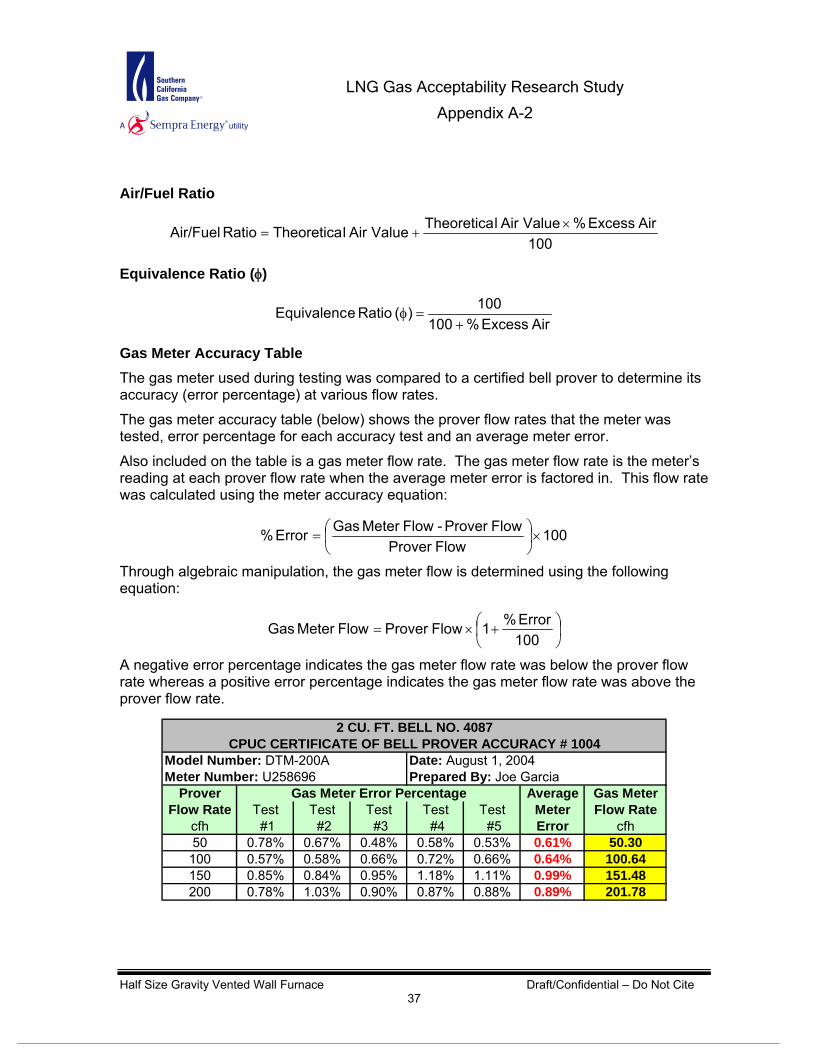
Air/Fuel Ratio
100 AirExcess % Value AirlTheoretica Value AirlTheoreticaRatio Air/Fuel ×
+=
Equivalence Ratio (φ)
AirExcess %100100)( Ratio eEquivalenc
+=φ
Gas Meter Accuracy Table The gas meter used during testing was compared to a certified bell prover to determine its accuracy (error percentage) at various flow rates.
The gas meter accuracy table (below) shows the prover flow rates that the meter was tested, error percentage for each accuracy test and an average meter error.
Also included on the table is a gas meter flow rate. The gas meter flow rate is the meter’s reading at each prover flow rate when the average meter error is factored in. This flow rate was calculated using the meter accuracy equation:
100Flow Prover
Flow Prover-Flow Meter GasError % ×⎟⎠⎞
⎜⎝⎛=
Through algebraic manipulation, the gas meter flow is determined using the following equation:
⎟⎠⎞
⎜⎝⎛ +×=
100Error %1Flow ProverFlow Meter Gas
A negative error percentage indicates the gas meter flow rate was below the prover flow rate whereas a positive error percentage indicates the gas meter flow rate was above the prover flow rate.
Prover Average Gas MeterFlow Rate Test Test Test Test Test Meter Flow Rate
cfh #1 #2 #3 #4 #5 Error cfh50 0.78% 0.67% 0.48% 0.58% 0.53% 0.61%
0.64%0.99%0.89%
50.30100 0.57% 0.58% 0.66% 0.72% 0.66% 100.64150 0.85% 0.84% 0.95% 1.18% 1.11% 151.48200 0.78% 1.03% 0.90% 0.87% 0.88% 201.78
Prepared By: Joe GarciaModel Number: DTM-200AMeter Number: U258696
Gas Meter Error Percentage
2 CU. FT. BELL NO. 4087CPUC CERTIFICATE OF BELL PROVER ACCURACY # 1004
Date: August 1, 2004
LNG Gas Acceptability Research Study
Appendix A-2
Half Size Gravity Vented Wall Furnace Draft/Confidential – Do Not Cite 38
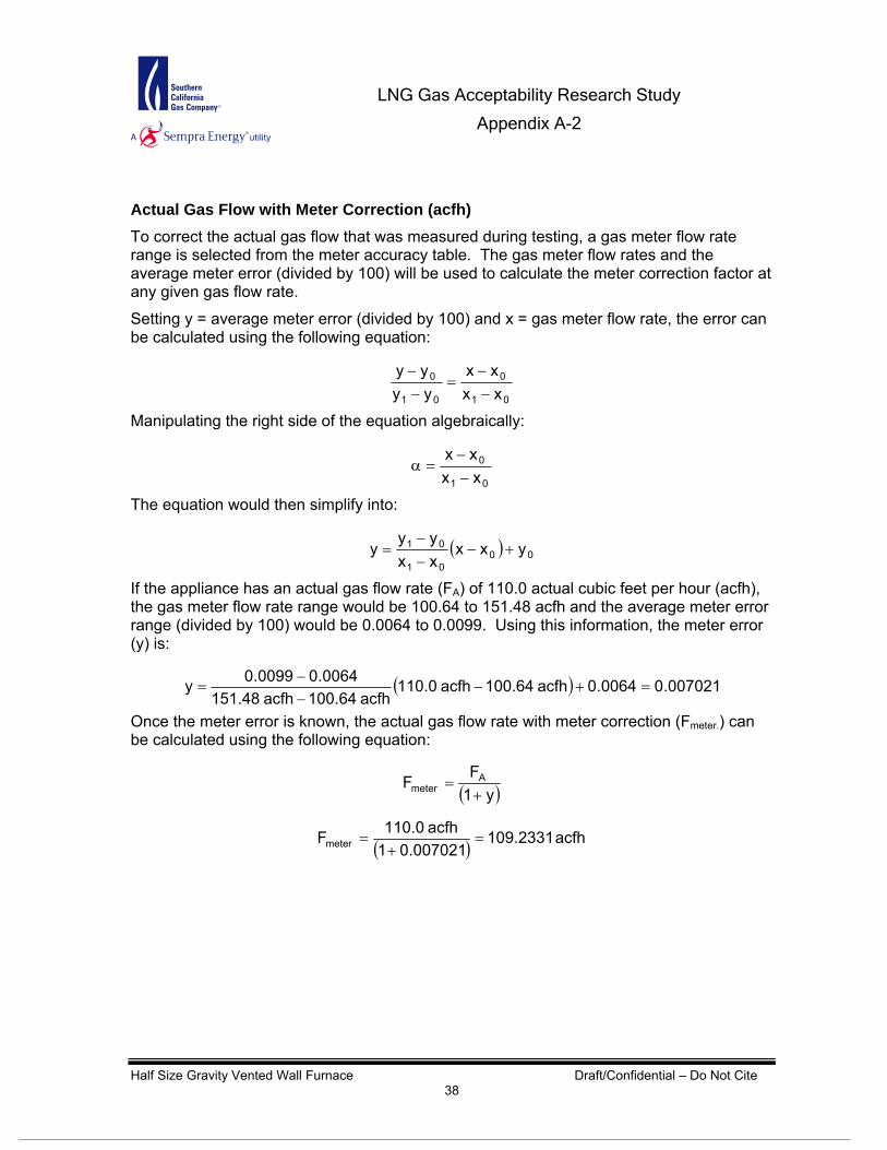
Actual Gas Flow with Meter Correction (acfh) To correct the actual gas flow that was measured during testing, a gas meter flow rate range is selected from the meter accuracy table. The gas meter flow rates and the average meter error (divided by 100) will be used to calculate the meter correction factor at any given gas flow rate.
Setting y = average meter error (divided by 100) and x = gas meter flow rate, the error can be calculated using the following equation:
01
0
01
0
xxxx
yyyy
−−
=−−
Manipulating the right side of the equation algebraically:
01
0
xxxx
−−
=α
The equation would then simplify into:
( ) 0001
01 yxxxxyy
y +−−−
=
If the appliance has an actual gas flow rate (FA) of 110.0 actual cubic feet per hour (acfh), the gas meter flow rate range would be 100.64 to 151.48 acfh and the average meter error range (divided by 100) would be 0.0064 to 0.0099. Using this information, the meter error (y) is:
( ) 007021.00064.0acfh 100.64acfh 110.0acfh 100.64acfh 151.48
0064.00099.0y =+−−−
=
Once the meter error is known, the actual gas flow rate with meter correction (Fmeter.) can be calculated using the following equation:
( )y1F
F Ameter +
=
( ) acfh 109.2331007021.01
acfh 110.0Fmeter =+
=

LNG Gas Acceptability Research Study
Appendix A-2
Half Size Gravity Vented Wall Furnace Draft/Confidential – Do Not Cite 39
Corrected Gas Flow (scfh)
( )⎥⎥⎦
⎤
⎢⎢⎣
⎡
+×⎥
⎦
⎤⎢⎣
⎡ +×=
459.67F)( TT
P(psia) Ppsig P
FFFuel
standard
standard
1Fuelmetercorrected o
Where
Fcorrected = Gas flow corrected to standard temperature and pressure (scfh)
Fmeter = Actual gas flow with meter correction (acfh)
FuelP = Natural gas supply pressure (psig)
1P = Average pressure in Pico Rivera at an average elevation of 161 ft (psia)
standardP = Standard atmospheric pressure (14.735 psia @ 60°F)
standardT = Standard atmospheric temperature (519.67 R @ 1 atm)
FuelT = Fuel temperature (°F)
Input Rate (Btu/cf)
HHVFlow Gas CorrectedRateInput ×=
Where
HHV = Higher Heating Value (Btu/cf)
Wobbe Number (Btu/cf)
GHHVW0 =
Where
W0 = Wobbe Number (Btu/cf)
HHV = Higher Heating Value (Btu/cf)
G = Specific gravity of gas sample

LNG Gas Acceptability Research Study
Appendix A-2
Half Size Gravity Vented Wall Furnace Draft/Confidential – Do Not Cite 40
Analyzer Manufacturer Model Type Accuracy
NO/NOX Thermo Environmental
Instruments Inc. 10AR Chemiluminescent ± 1% of full scale
CO Thermo Environmental Instruments Inc. 48 Nondispersive infrared (NDIR)
gas analyzer ± 1% of full scale
CO2 Fuji ZRH Nondispersive infrared (NDIR) gas analyzer ± 1% of full scale
HC California Analytical Instruments, Inc. 300 HFID Flame ionization detector (FID) ± 1% of full scale
O2 Teledyne 326RA Electrochemical cell ± 1% of full scale
Gas Manufacturer Accuracy
Calibration Scott Specialty Gases ± 2%
NO/NOX Scott Specialty Gases ± 2%
CO Scott Specialty Gases ± 2%
CO2 Scott Specialty Gases ± 2%
HC Scott Specialty Gases ± 2%
O2 Scott Specialty Gases ± 2%
Equipment Model Accuracy
Datalogger D51515 n/a
Gas Chromatograph 6890 ± 0.5 BTU/scf
K KMQSS 2.2oC or 0.75%
J JMQSS 2.2oC or 0.75%
T TMQSS 2.2oC or 0.75%Dry Test Gas Meter
200 cf/h max DTM-200A @ 200 cf/h – 100.1 %@60 cf/h – 99.9 %
Gas Meter Pulser2 pulses per 1/10 cf 4008468 n/a
Gas Pressure Regulator 299H ± 1.0 %
Differential Pressure Transmitter 607-4 ±0.25 -0.50%
Pressure Transducer PX205-100GI ±0.25% of full scale Omega
Omega Engineering Co.
Omega Engineering Co.
Dwyer
Fisher
Manufacturer
American Meter Company
Rio Tronics
Delphin
Agilent
Omega Engineering Co.
Emissions Analyzer
Test Equipment
Calibration & Span Gases
Type
Certified Master Class - 18.95 ppm
Certified Master Class - 0.5 ppm
Certified Master Class - 9.1 %
Certified Master Class - 0 %
Certified Master Class -12.1 %
Certified Master Class - 79.3 ppm
Appendix F: Test Equipment All emissions analyzers, analyzer calibration gases and instrumentation meet CARB and SCAQMD standards.

LNG Gas Acceptability Research Study
Appendix A-2
Half Size Gravity Vented Wall Furnace Draft/Confidential – Do Not Cite 41
BALL VALVE
BALLVALVE
REGULATOR
REGULATOR
PRESSURE TEMPERATURE GAS METERW ITH PULSER
GASCYLINDERS
EMISSIONANALYZER
O2, CO2CO, NOx
HC
END-USEREQUIPMENT
TEST RIG
LAPTOP
DATALOGGER
DATA LOGGER
TP
P
COMPUTER
THERMOCOUPLES
BASELINEGAS
T
BALL VALVE
HEAT EXCHANGER
Appendix G: Test Set-Up/Schematic Equipment utilized for testing adheres to industry standards for testing laboratories that certify such equipment. The test rig is transportable and includes a data logger, emissions cart, gas meter, thermocouples and pressure transducers; plus, a gas regulation system that can take natural gas from 3,000 psig and deliver up to 2,000 cubic feet per hour (cfh) at low pressure (approx. 8 in w.c.). The test rig is illustrated below.

LNG Gas Acceptability Research Study
Appendix A-2
Half Size Gravity Vented Wall Furnace Draft/Confidential – Do Not Cite 42
Appendix H: Half Size Wall Furnace Setup
1 Side Wall Temperature
2 Upper Wall Temperature
3 Back Wall Temperature
4 Exhaust Gas Discharge
5 Inlet Air to Burner