lncs 8888 - 3d previsualization using a computational ...emmanuel/publications/pdfs/c20.pdf · 3d...
TRANSCRIPT
G. Bebis et al. (Eds.): ISVC 2014, Part II, LNCS 8888, pp. 904–914, 2014. © Springer International Publishing Switzerland 2014
3D Previsualization Using a Computational Photography Camera
Clifford Lindsay and Emmanuel Agu
Worcester Polytechnic Institute, Worcester, MA
Abstract. During movie production, movie directors use previsualization tools to convey the movie visuals as they see them in their minds eye. Traditional methods of previsualization include hand-drawn sketches, storyboards and still photographs. Recently, video game engines have been used for previsualization so that once the movie set is modeled, scene lighting, geometry, textures and various scene elements can be changed interactively and the effects of many po-tential changes can be previewed quickly. The use of video games for previsua-lization involves manually modeling the movie set by artists to create a digital version, which is expensive. We envision that a computational photography camera can be used for capturing images of a physical set from which a model of the scene can be automatically generated. A wide range of possible changes can be explored interactively and previewed on-set including scene geometry and textures. Since our vision is large, we focus initially on an initial prototype (a computational photography camera and previsualization algorithms), which enable scene lighting to be captured, inferred, manipulated and new lights ap-plied (relighting). Evaluations of our light previsualization prototype shows low photometric error rates and encouraging feedback from experts.
1 Introduction
Movie making is the process of storytelling using creative visuals and audio scenes. While designing the movie set, its physical configuration must be matched to the director’s artistic vision. Previsualization techniques are used to create approximate previews of a movie sequence prior to shooting it. Often these techniques are used to convey the artistic direction of the story in terms of cinematic elements, such as cam-era movement, angle, lighting, dialogue, and character motion. Essentially, a movie director uses previsualization (previs) to convey movie visuals as he sees them in his ”minds-eye”. Traditional methods for previs include hand-drawn sketches, story-boards and photographs to convey how a scene or character might look or move.
A recent trend has emerged whereby 3D video game engines are used to design movie sets and perform previsualization (called 3D previsualization). By understand-ing the effects of the various options available to the filmmakers prior to shooting, previsualization can help to minimize reshoots, save time, money, and facilitate the creative process [1]. Digital previsualization platforms have the advantage that once a scene is digitally modeled, visualizing changes to the scene can be done interactively and the effects of many potential changes can be previewed quickly. However, using
3D Previsualization Using a Computational Photography Camera 905
video games for previsualization involves manually modeling the movie set by artists to create a digital version, which is expensive. Consequently, digital platforms for previsualization are currently used mostly by big movie companies.
Our Vision. Computational photography cameras and algorithms have recently emerged [2]. We envision that a computational photography camera (hardware, algo-rithms and software) can be used for interactive 3D previsualization. A digital model of movie set can be automatically generated from a picture (or pictures). Various scene configurations can be explored by the director including lighting choices, movie furniture, props and object materials in order to guide on-set design choices.
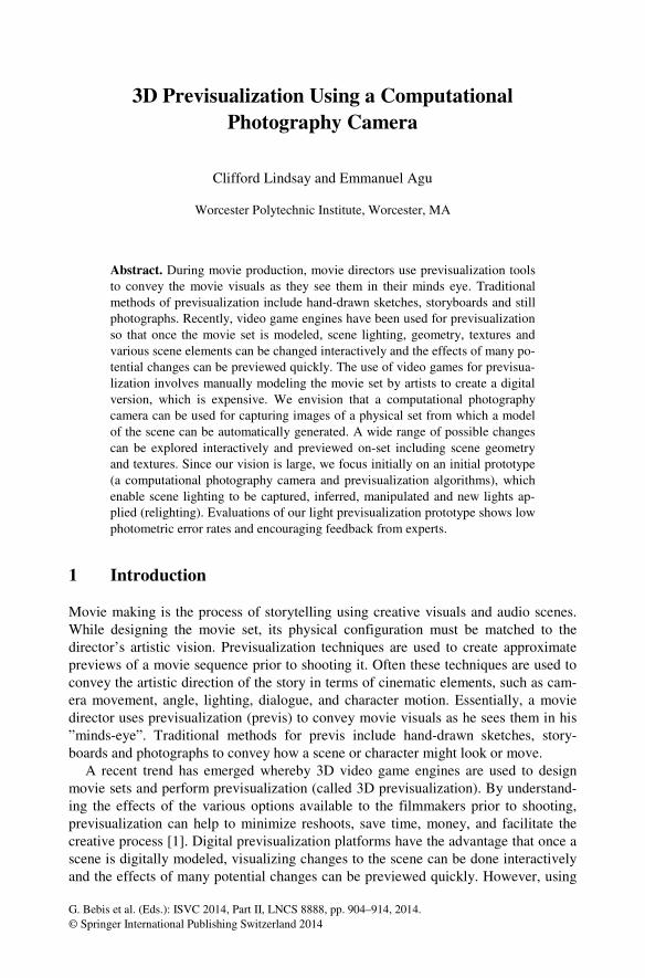
Fig. 1. Our envisioned previsualization interface that facilitates the virtual capture and edit all of a movie scene’s properties including geometry, object reflectance, texture, shadows and lights
Figure 1 is a mock-up of our envisioned previsualization interfacen. Using our computational previsualization camera (hardware, algorithms and software), a movie set is digitized in real time to capture scene objects, material, lighting and textures, which can be edited on-set by the movie director to view the effect of changes. In the figure, a scene object has been selected by the user via the interface (red dotted line). The interface then provides all the options for editing the real object virtually such as textures, reflectance, geometry, and lighting changes and previewing the changes in real-time. This tool would provide the same level of control for visualization as 3D modeling tools such as Maya or 3D Studio max on-camera.
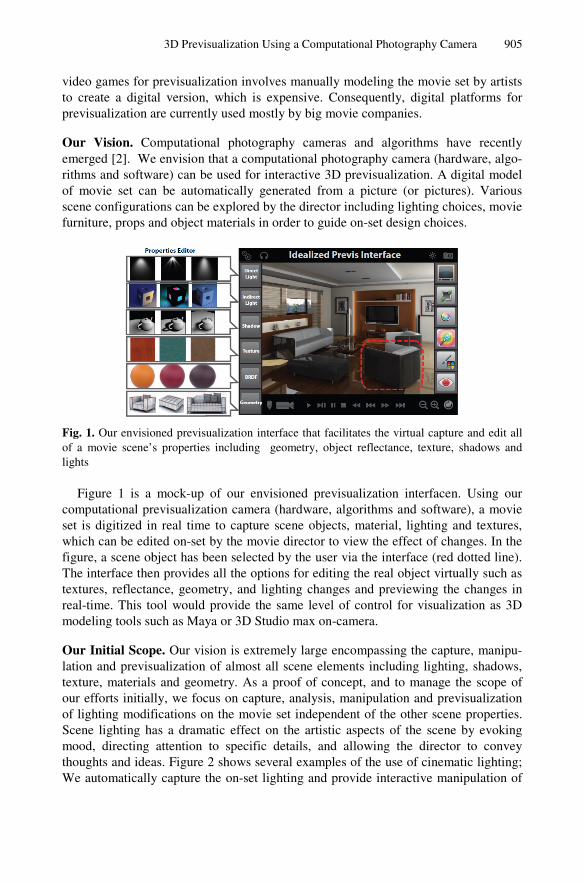
Our Initial Scope. Our vision is extremely large encompassing the capture, manipu-lation and previsualization of almost all scene elements including lighting, shadows, texture, materials and geometry. As a proof of concept, and to manage the scope of our efforts initially, we focus on capture, analysis, manipulation and previsualization of lighting modifications on the movie set independent of the other scene properties. Scene lighting has a dramatic effect on the artistic aspects of the scene by evoking mood, directing attention to specific details, and allowing the director to convey thoughts and ideas. Figure 2 shows several examples of the use of cinematic lighting; We automatically capture the on-set lighting and provide interactive manipulation of
906 C. Lindsay and E. Agu
cinematic elements to facilitate the movie maker’s artistic expression, validate cine-matic choices, and provide guidance to production crews.
Fig. 2. A collage of example lighting concepts that illustrate diverse types of scene lighting
Our Key Contributions. We propose a five-tiered framework: 1) Symmetric lighting: new algorithms that analyzes and decomposes the scene photometrically to infer cur-rent scene lighting, and 2) β (beta) map: a novel data structure for storing captured light, which facilitates editing and relighting. 3) Light editing: functionality to modify the captured scene lighting using gradient domain operations. 4) Scene relighting: a technique to apply new lighting to the movie scene and 6) PCam: a novel programm-able camera architecture that is fully programmable and a user interface that facilitates scene capture, analysis, editing and previsualization by novices.
2 Symmetric Light
Symmetric Lighting is our novel technique for inferring the lighting conditions under which an image of a scene (movie set) was initially captured without knowing or measuring its geometry, reflectance, or appearance and without the need for light measurement equipment as is typically used today. An outline of the Symmetric Light technique is now provided. We assume that the light source colors are distinct and known by the user a priori, and calculate the effects of these lights at each image pixel due to the different colored light sources. Under this condition, every pixel receives a mixture of these two distinct light sources L1 and L2 either directly or after being re-flected off a material surface. If an image pixel receives a mixture of L1 and L2, in RGB space λ ={R, G, B}, an image sensor has three color values our input image can be modeled as:
(1)
We recover the direct and global elements of light using a technique called Active illumination. Active Illumination is the name given to a class of Computational
3D Previsualization Using a Computational Photography Camera 907
Photography [4] methods that manipulate only the lighting in a scene in order to esti-mate scene properties. In our Symmetric Lighting method, we manipulate the lighting by alternating the color each light emits, which allows us to estimate the proportion each light contributes to illuminating a given camera pixel. Thus to infer what light impinges on a pixel, we position the lights in the appropriate location in the RGB color cube based on their light color. Then using interpolation, we assume that each pixel, located at (x,y) in image I, has a relative contribution of light from each illumi-nant in the form:
21 )1( LLL ββ −+= (2)
Since we assume knowledge of L1 and L2, determing the light L received by a given pixel reduces to finding it’s value of β (contributions received from L1 and L2). To solve for β we introduce the novel idea of Symmetric Lighting, which allows us to introduce further constraints on the ill-constrained formulation for determining β. The idea is that while keeping the camera and light positions constant and assuming the lights emit different colored light, we acquire two images of the scene. After acquiring the first image, the second image is acquired with the colors between lights swapped.
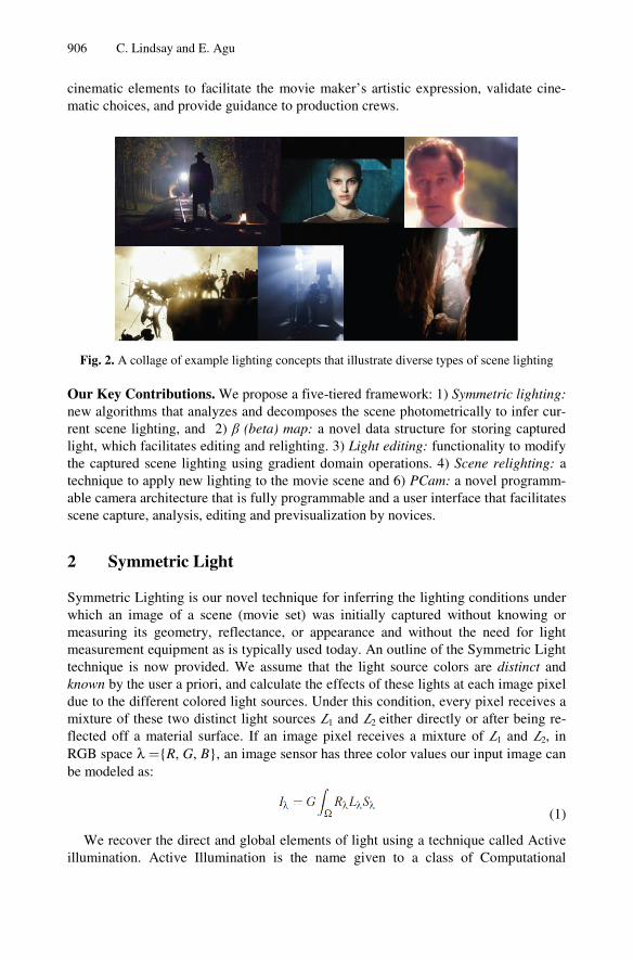
Using Euclidean geometry in the RGB color cube, we can solve for the values of the two lights sources. If we plot the light colors of L1 and L2 in the RGB cube, they form two points in the cube. The line between L1 and L2 in the color cube is in fact the range of light colors (mixtures) any pixel image can receive. If we then multiply the light line segment
21LL by a pixel of the color C1, this corresponds to a transform
of the line segment to a new location in the RGB cube, call it 211 LLC . The new line
segment 211 LLC spans a color range, where every point on the line segment is some
interpolation of the end points C1L1 and C1L2 where β is the interpolation variable. If we also consider a second transformation of
21LL by a different pixel color C2, this
forms a different line segment, call it 212 LLC . We find the proper interpolant value β
that solves these equations. Then the solution is just the β value where 211 LLC and
212 LLC intersect as indicated in Figure 3.
Fig. 3. The relationship between camera pixel C1 and C2 in successive images at the same pixel location (i, j) and the two lights that provide a relative contribution in linear RGB space
908 C. Lindsay and E. Agu
The above formulation assumes 2 lights but we also derive a more general form for inferring the colors of N different lights. We refer the reader to [5] for the full deri-vation and also our technique for minimizing light estimation errors.
3 The Beta Map
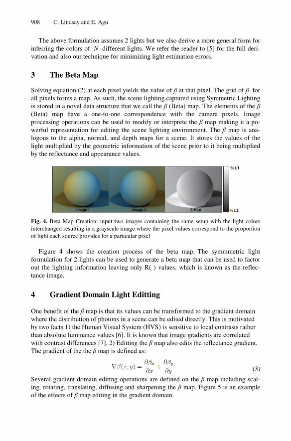
Solving equation (2) at each pixel yields the value of β at that pixel. The grid of β for all pixels forms a map. As such, the scene lighting captured using Symmetric Lighting is stored in a novel data structure that we call the β (Beta) map. The elements of the β (Beta) map have a one-to-one correspondence with the camera pixels. Image processing operations can be used to modify or interprete the β map making it a po-werful representation for editing the scene lighting environment. The β map is ana-logous to the alpha, normal, and depth maps for a scene. It stores the values of the light multiplied by the geometric information of the scene prior to it being multiplied by the reflectance and appearance values.
Fig. 4. Beta Map Creation: input two images containing the same setup with the light colors interchanged resulting in a grayscale image where the pixel values correspond to the proportion of light each source provides for a particular pixel
Figure 4 shows the creation process of the beta map. The symmmetric light formulation for 2 lights can be used to generate a beta map that can be used to factor out the lighting information leaving only R( ) values, which is known as the reflec-tance image.
4 Gradient Domain Light Editting
One benefit of the β map is that its values can be transformed to the gradient domain where the distribution of photons in a scene can be edited directly. This is motivated by two facts 1) the Human Visual System (HVS) is sensitive to local contrasts rather than absolute luminance values [6]. It is known that image gradients are correlated with contrast differences [7]. 2) Editting the β map also edits the reflectance gradient. The gradient of the the β map is defined as:
(3)
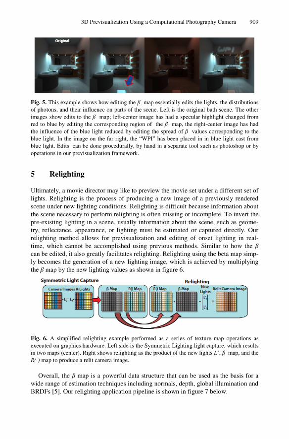
Several gradient domain edittng operations are defined on the β map including scal-ing, rotating, translating, diffusing and sharpening the β map. Figure 5 is an example of the effects of β map editing in the gradient domain.
3D Previsualization Using a Computational Photography Camera 909
Fig. 5. This example shows how editing the β map essentially edits the lights, the distributions of photons, and their influence on parts of the scene. Left is the original bath scene. The other images show edits to the β map; left-center image has had a specular highlight changed from red to blue by editing the corresponding region of the β map, the right-center image has had the influence of the blue light reduced by editing the spread of β values corresponding to the blue light. In the image on the far right, the “WPI” has been placed in in blue light cast from blue light. Edits can be done procedurally, by hand in a separate tool such as photoshop or by operations in our previsualization framework.
5 Relighting
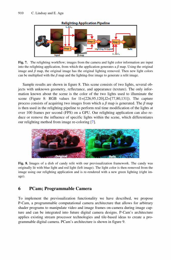
Ultimately, a movie director may like to preview the movie set under a different set of lights. Relighting is the process of producing a new image of a previously rendered scene under new lighting conditions. Relighting is difficult because information about the scene necessary to perform relighting is often missing or incomplete. To invert the pre-existing lighting in a scene, usually information about the scene, such as geome-try, reflectance, appearance, or lighting must be estimated or captured directly. Our relighting method allows for previsualization and editing of onset lighting in real-time, which cannot be accomplished using previous methods. Similar to how the β can be edited, it also greatly facilitates relighting. Relighting using the beta map simp-ly becomes the generation of a new lighting image, which is achieved by multiplying the β map by the new lighting values as shown in figure 6.
Fig. 6. A simplified relighting example performed as a series of texture map operations as executed on graphics hardware. Left side is the Symmetric Lighting light capture, which results in two maps (center). Right shows relighting as the product of the new lights L’, β map, and the R( ) map to produce a relit camera image.
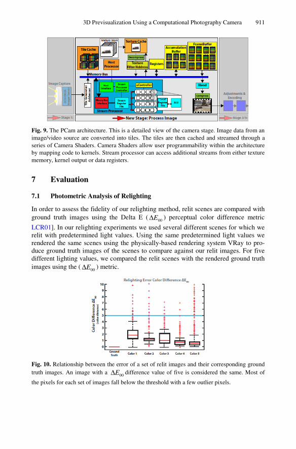
Overall, the β map is a powerful data structure that can be used as the basis for a wide range of estimation techniques including normals, depth, global illumination and BRDFs [5]. Our relighting application pipeline is shown in figure 7 below.
910 C. Lindsay and E. Agu
Fig. 7. The relighting workflow; images from the camera and light color information are input into the relighting application, from which the application generates a β map. Using the original image and β map, the original image has the original lighting removed. Then new light colors can be multiplied with the β map and the lighting-free image to generate a relit image.
Sample results are shown in figure 8. This scene consists of two lights, several ob-jects with unknown geometry, reflectance, and appearance (texture). The only infor-mation known about the scene is the color of the two lights used to illuminate the scene (Figure 8: RGB values for l1=[226,95,120],l2=[77,80,131]). The capture process consists of acquiring two images from which a β map is generated. The β map is then used in the relighting pipeline to perform real time modification of the lights at over 100 frames per second (FPS) on a GPU. Our relighting application can also re-duce or remove the influence of specific lights within the scene, which differentiates our relighting method from image re-coloring [7].
Fig. 8. Images of a dish of candy relit with our previsualization framework. The candy was originally lit with blue light and red light (left image). The light color is then removed from the image using our relighting application and is re-rendered with a new green lighting (right im-age).
6 PCam; Programmable Camera
To implement the previsualization functionality we have described, we propose P-Cam, a programmable computational camera architecture that allows for arbitrary shader programs to manipulate video and image frames on-camera during image cap-ture and can be integrated into future digital camera designs. P-Cam’s architecture applies existing stream processor technologies and tile-based ideas to create a pro-grammable digital camera. PCam’s architecture is shown in figure 9.
3D Previsualization Using a Computational Photography Camera 911
Fig. 9. The PCam architecture. This is a detailed view of the camera stage. Image data from an image/video source are converted into tiles. The tiles are then cached and streamed through a series of Camera Shaders. Camera Shaders allow user programmability within the architecture by mapping code to kernels. Stream processor can access additional streams from either texture memory, kernel output or data registers.
7 Evaluation
7.1 Photometric Analysis of Relighting
In order to assess the fidelity of our relighting method, relit scenes are compared with ground truth images using the Delta E ( 00EΔ ) perceptual color difference metric
LCR01]. In our relighting experiments we used several different scenes for which we relit with predetermined light values. Using the same predetermined light values we rendered the same scenes using the physically-based rendering system VRay to pro-duce ground truth images of the scenes to compare against our relit images. For five different lighting values, we compared the relit scenes with the rendered ground truth images using the ( 00EΔ ) metric.
Fig. 10. Relationship between the error of a set of relit images and their corresponding ground truth images. An image with a 00EΔ difference value of five is considered the same. Most of
the pixels for each set of images fall below the threshold with a few outlier pixels.
912 C. Lindsay and E. Agu
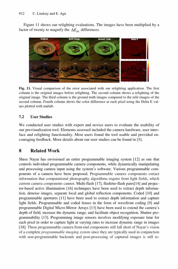
Figure 11 shows our relighting evaluations. The images have been multiplied by a factor of twenty to magnify the 00EΔ differences.
Fig. 11. Visual comparison of the error associated with our relighting application. The first column is the original images before relighting. The second column shows a relighting of the original image. The third column is the ground truth images compared to the relit images of the second column. Fourth column shows the color difference at each pixel using the Delta E val-ues plotted with matlab.
7.2 User Studies
We conducted user studies with expert and novice users to evaluate the usability of our previsualization tool. Elements assessed included the camera hardware, user inter-face and relighting functionality. Most users found the tool usable and provided en-couraging feedback. More details about our user studies can be found in [5].
8 Related Work
Shree Nayar has envisioned an entire programmable imaging system [12] as one that controls individual programmable camera components, while dynamically manipulating and processing camera input using the system’s software. Various programmable com-ponents of a camera have been proposed. Programmable camera components extract information that computational photography algorithms require from light fields, which current camera components cannot. Multi-flash [17], flash/no-flash pairs[14] and projec-tor-based active illumination [16] techniques have been used to extract depth informa-tion, denoise images, separate local and global reflection components. Coded [10] and programmable apertures [11] have been used to extract depth information and capture light fields. Programmable and coded lenses in the form of wavefront coding [9] and programmable Digital Micro-Mirror Arrays [13] have been used to extend the camera’s depth of field, increase the dynamic range, and facilitate object recognition. Shutter pro-grammability [13]. Programming image sensors involves modifying exposure time for each pixel in order to capture light at varying rates to increase dynamic range in images [18]. These programmable camera front-end components still fall short of Nayar’s vision of a complete programmable imaging system since they are typically used in conjunction with non-programmable backends and post-processing of captured images is still re-
3D Previsualization Using a Computational Photography Camera 913
quired before the final image can be generated. The FrankenCamera [2] includes a pro-grammable back end but it is not specifically purposed for previsualization.
9 Conclusion and Future Work
We have described a comprehensive vision of algorithms and a programmable camera for previsualization which allows a movie set to be captured and manipulated on-set in real time. We have built a prototype focusing on light capture, edit, manipulation and relighting. In future, we hope to attack other scene elements including geometery, material and textures.
References
1. Okun, J.A., Zwerman, S.: The VES Handbook of Visual Effects: Industry Standard VFX Practices and Procedures. Focal Press, ElsevierScience (2010)
2. Adams, A., et al.: The frankencamera: an experimental platform for computational photo-graphy. In: Proc ACM SIGGRAPH (2010)
3. Warner brothers, HBO Entertainement, and Fox Searchlight Pictures. Movie collage (April 2011)
4. Raskar, R., Tumblin, J., Mohan, A., Agrawal, A., Li, Y.: Computational photography. ACM / EG Computer Graphics Forum 25(3), 1–20 (2006)
5. Lindsay, C.: Programmable Image-Based Light Capture for Previsualization, PhD Disser-tation, Worcester Polytechnic Institute (January 2013)
6. Ruppertsberg, A.I., Bloj, M., Hurlbert, A.: Sensitivity to luminance and chromaticity gradients in a complex scene. Journal of Vision 8(9) (2008)
7. Bhat, P., Lawrence Zitnick, C., Cohen, M., Curless, B.: Gradientshop: A gradient-domain optimization framework for image and video filtering. ACM Trans. Graphics 29(2), 10 (2010)
8. Reinhard, E., Ashikhmin, M., Gooch, B., Shirley, P.: Color transfer between images. IEEE Comput. Graph. Appl. 21(5), 34–41 (2001)
9. Edward, J., Dowski, R., Cathey, W.T.: Extended depth of field through wave-front coding. Appl.Opt. 34(11), 1859–1866 (1995)
10. Levin, A., Fergus, R., Durand, F., Freeman, W.T.: Image and depth from a conventional camera with a coded aperture. ACM Trans. Graph. 26(3), 70 (2007)
11. Liang, C.-K., Lin, T.-H., Wong, B.-Y., Liu, C., Chen, H.: Programmable aperture photography: Multiplexed light field acquisition. ACM Transactions on Graphics 27(3), 55:1–55:10 (2008)
12. Nayar, S.: Computational cameras: Redefining the image. IEEE Computer Mag., 30–38 (August 2006)
13. Nayar, S., Branzoi, V., Boult, T.: ProgrammableImaging using a Digital Micromirror Array. In: IEEE Conference on Computer Vision and Pattern Recognition vol. I, pp. 436–443 (June 2004)
14. Petschnigg, G., Agrawala, M., Hoppe, H., Szeliski, R., Cohen, M., Toyama, K.: Digital photography with flash and no-flash image pairs. In: ACM Trans Graphics (Proceedings of SIGGRAPH 2004) (2004)

914 C. Lindsay and E. Agu
15. Raskar, R., Agrawal, A., Tumblin, J.: Coded exposure photography: motion deblurring using fluttered shutter. ACM Trans. Graph. 25(3), 795–804 (2006)
16. Zhang, L., Nayar, S.K.: Projection Defocus Analysis for Scene Capture and Image Display. ACM Trans. on Graphics (July 2006)
17. Raskar, R., Tan, K.-H., Feris, R., Yu, J., Turk, M.: Non-photorealistic camera: depth edge detection and stylized rendering using multi-flash imaging. In: ACM SIGGRAPH 2005, p. 2. ACM (2005)
18. Nayar, S., Branzoi, V.: Adaptive Dynamic Range Imaging: Optical Control of Pixel Exposures over Space and Time. In: IEEE Intl. Conf. on Computer Vision, vol. 2, pp. 1168–1175 (October 2003)