lithium battery energy solution · 2018-11-08 · energy solution lg chem model no. em48126p3s |...
TRANSCRIPT

I N C O R P O R A T I N G
ENERGY SOLUTION
LG CHEM MODEL NO. EM48126P3S | ABB DC DISTRIBUTION BOARDS
Installation Guide
VER
SIO
N 1
.5
L I T H I U M B AT T E R Y

Contents
3. Notices
4. Before You Begin
7. Bill of Materials
8. Warnings
9. Cautions
12. Battery Specifications
13. DB Specifications
14. Weights & Dimensions
15. Battery Details
16. Battery Electrical Schematics
18. Installation Process
49. Battery Status Lights
50. Battery Fault Scale
51. Select Alerts
52. Full List of Alerts
53. Completing Installation
54. Battery Warranty
55. Picking Lists 2

Notices
About This Manual • This manual describes how to install LG Chem EM048126P3S series
lithium rack mounted battery modules into a supplied Cabinet and wire them to a supplied DC Distribution Board.
• Read this manual all the way through before you attempt installation and follow the instructions throughout the installation process.
• If you are uncertain about any of the requirements, recommendations, or safety procedures described in this manual, contact your supplier immediately for advice and clarification.
• The information included in this manual is accurate at the time of publication. However the product specifications are subject to change without prior notice. In addition the illustrations in this manual are meant to help explain system configuration concepts and installation instructions. The illustrated items may differ from the actual items at the installation location
3
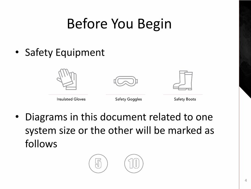
Before You Begin
• Safety Equipment
• Diagrams in this document related to one system size or the other will be marked as follows
4

Before You Begin
• Installation Prerequisites
5
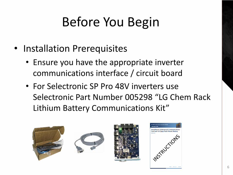
Before You Begin
• Installation Prerequisites
• Ensure you have the appropriate inverter communications interface / circuit board
• For Selectronic SP Pro 48V inverters use Selectronic Part Number 005298 “LG Chem Rack Lithium Battery Communications Kit”
6

Bill Of Materials
7
Component 5 Battery System 10 Battery System
LG Chem EM048126P3Sx 6.5kWh lithium battery modules 3-5 based on order 5-10 based on order
Communication Cable: Inter-battery 1 per Battery less 1 i.e. 3 cables for 4 batteries
Communication Cable: First Battery to DB9 Female 1 per System
DC cables (red & black) 1 pair per Battery
Cable Glands – 16mm for data 1
Cable Glands – 28mm for fan controller power 1
Cable Glands – 35mm for DC cable to inverter 2
Cable Glands – 63mm for DC cables from batteries 1 2
70mm2 cable lugs 2
Temperature control unit for fans with four nuts & bolts 1
Rack Mount Cabinet 22RU to hold up to 5 batteries 37RU to hold up to 10 batteries
Set of four levelling feet for Cabinet 1
Cabinet shelves 5 10
Nuts & bolts for shelves (4 per shelf) 20 40
Nuts & bolts for securing modules (4 per module) 20 40
DC Distribution Board For 5 batteries For 10 batteries
Installation manual (this document) 1

Warnings
• Read the LG Chem battery installation manual for a complete list of warnings and response to emergency situations including fire and damaged batteries.
• Risk of shock-high DC current.
• Hazardous weight of each battery module.
8

Cautions
• Read the LG Chem battery installation manual for information on battery handling and personal protective equipment to be worn.
• Installation is to be in a dry, clean environment – do not expose to moisture or dust.
• The installation location should be secured against vermin including rodents, reptiles and all types of insects.
9

Cautions cont.
• Ensure that the floor of the installation location is flat, level and suitably rated for the weight of the battery Cabinet, which with 10 batteries weighs approximately 500kg.
• Do not move Cabinet with batteries installed –set the Cabinet in its final location before battery installation.
• Only use leveling feet if necessary.
• Install batteries from the bottom shelf up.
10

Cautions cont.
• It is strongly advised that the SP Pro be connected to the internet for remote access to assist with any warranty claim on the batteries.
• Note: a complete download of the battery logging data from the SP Pro inverter is required for any battery warranty claim.
11

Parameter EM48126P3S
Battery available operating temperature −10°C ~ 45°C
Battery optimal operating temperature 15°C ~ 30°C
Humidity 5 to 95% (non-condensing)
Nominal Capacity 126Ah
Nominal Energy 6.5kWh
Nominal Voltage 51.8Vdc
Operating Voltage 42 ~ 58.8Vdc
Maximum Charge/Discharge Current 63A
Round Trip Efficiency 95%+
Maximum Short Circuit Current 1,897A
Fuse Blowing Time 3.2 msec
Battery Specifications
12

5 Battery Cabinet 10 Battery Cabinet
ABB Circuit Breakers 5 x S802C-C80 80A MCB 10 x S802C-C80 80A MCB
ABB Distribution Blocks DBL400 DBL400
ABB Main Isolators Tmax XT 250A MCCB Tmax XT 250A MCCB
Escutcheon Standard Standard
Distribution Board Specifications
13

5 Battery Cabinet 10 Battery Cabinet
Cabinet (mm) 600 (W) x 1100 (H) x 800 (D) 600 (W) x 1750 (H) x 800 (D)
Cabinet (kg) 71kg 120kg
Battery Module (mm) 483 (W) x 110 (H) x 586.6 (D)
Battery Module (kg) 44kg
Distribution Board (mm) 600 (W) x 900 (H) x 225 (D) 600 (W) x 1100 (H) x 225 (D)
Distribution Board (kg) 50kg 60kg
Weights & Dimensions
14

Battery Details
1. Status indicators
2. RJ48 port (intra-rack)
3. RJ48 port (inverter)
4. Positive connector
5. Power Terminal Compartment
6. Negative connector
7. On/Off button
8. Dry contact
9. Handle (not rated for 44kg) 15

Battery Electrical Schematic
16

Battery Electrical Schematic
17

Installation Process
1. Confirm installation location meets the requirement to be dry, clean and ideally temperature controlled plus has been secured against vermin.
2. Install leveling feet if necessary to ensure that the Cabinet is completely level.
18

Installation Process cont.
3. Ensure that the wall the Distribution Board is being affixed to is suitable load rated.
4. Measure out locations for installation of the Cabinet and Distribution Board.
• Align top of Distribution Board to top of Cabinet.
19

20
Align top of Distribution Board to top of Cabinet.

21
Align top of Distribution Board to top of Cabinet.

Installation Process cont.
5. Position the Cabinet in its final position hard up against the wall.
6. Remove both side panels from Cabinet.
7. Lie the Distribution Board on its back and remove the escutcheon, gland plate and internal pan.
22

Installation Process cont.
8. Mount the Distribution Board on the wall in its final position up against right hand side of the Cabinet.
9. Drill out 63mm gland(s) for DC cables from inside the Distribution Board right through to the inside of the Cabinet. • The DC cables must be routed through the back-
right side of the Cabinet into the Distribution Board due to the length of the DC cables.
23

24
Drill 1 x 63mm hole from inside the Distribution Board through and into the Cabinet.

25
Drill 2 x 63mm holes from inside the Distribution Board through and into the Cabinet.

Installation Process cont.
10.Drill out glands for the communication cable and the power cable to the Fan Controller.
• These cables may be routed through the back or sides of the Cabinet.
11.Vacuum out any metal shavings in the base of the Cabinet.
26

Installation Process cont.
12.Install all cable glands.
• The 63mm DC cable gland(s) should go right through from the inside of the Cabinet to the inside of the Distribution Board.
13.Install shelves and fan controller into the Cabinet in the positions shown.
27

Shelf positions: 6, 17, 28, 39, 50
Fan controller: 61, 62
28

Shelf positions: 6, 16, 26, 36, 46, 56, 66, 76, 86, 96
Fan controller: 106, 108 29

Installation Process cont.
14.Run power cable for fan controller out of cabinet through gland.
30

Installation Process cont.
15.Re-install pan into Distribution Board.
16.Wire the DC cables for each battery to the circuit breakers in the Distribution Board.
Ensure polarities match
31

Installation Process cont.
17.Route each battery’s pair of DC cables through the 63mm cable glands into the Cabinet.
• Tag each cable 300mm back from the battery connector for later identification.
18.Leave all DC battery cables hanging out the right side of the Cabinet prior to final connection.
32

Installation Process cont.
19.Install batteries one at a time starting from the bottom shelf.
Warning – two people required to lift each battery
Warning – do not carry the battery only by the handle, it is not rated to carry the full weight of the battery
33

Installation Process cont.
20.Secure each battery with four module mounting bolts to the front mounting bars.
34

Installation Process cont.
21.Measure the voltage of each battery.
• Remove terminal compartment cover.
• Measure voltage at the terminal blocks with a volt meter. If voltage is lower than 42V do not use the battery module.
• Replace cover.
35

Installation Process cont.
22.Install the communications cables between the batteries.
• Starting at the top, insert one end of the intra-rack communication cable into the lower RJ48 port of the module and then insert other end into the upper RJ48 port of the module below.
• Leave the lower RJ48 port of the bottom-most battery unconnected.
36

Intra-battery Communications cables.
37

Installation Process cont.
23.Connect LG Chem RJ45 to DB 9 communications cable from top-most battery to the inverter through the cable gland.
• For SP Pro inverters this means connecting via the Selectronic LG Chem Stand Alone Battery Communications Kit (part no. 005298)
38

Communications cable to inverter.
39

Installation Process cont.
24.Connect each DC cable pair to a battery module – positive first, then negative.
24.Cable tie the DC cables to the internal uprights of the Cabinet.
40

Comms cables link from battery to battery.
DC cables run in parallel.
41

Comms cables link from battery to battery.
DC cables run in parallel.
42

Installation Process cont.
26.Crimp & heat-shrink 70mm2 lugs onto 70mm2 DC cable ready for termination in main isolator.
27.Install 70mm2 DC cable from the top of the main isolator at the top of the Distribution Board through to the inverter.
• Install glands into the Distribution Board gland plate if required.
• Install gland plate into the Distribution Board.
• Reinstate escutcheon in Distribution Board.
43

Installation Process cont.
28.Turn on the top most battery via the On/Off button.
• This designates the top battery as the master and activates not only the master module but also the slave modules.
44

Installation Process cont.
All of the battery modules are sequentially assigned IDs by the master module.
If the top module’s On/Off button is pressed, the module becomes the master module and also the first module.
45

Battery Status Lights
46

Installation Process cont.
29.Position Fan Controller temperature sensor above top-most battery module.
30.Power on Fan Controller and set for 25°C.
47

Installation Process cont.
31.Remove the nub screws from the base of the Cabinet’s right side panel.
32.Reinstate both Cabinet side panels.
33.Retain all left over parts (bolts, etc.) for future upgrades.
48
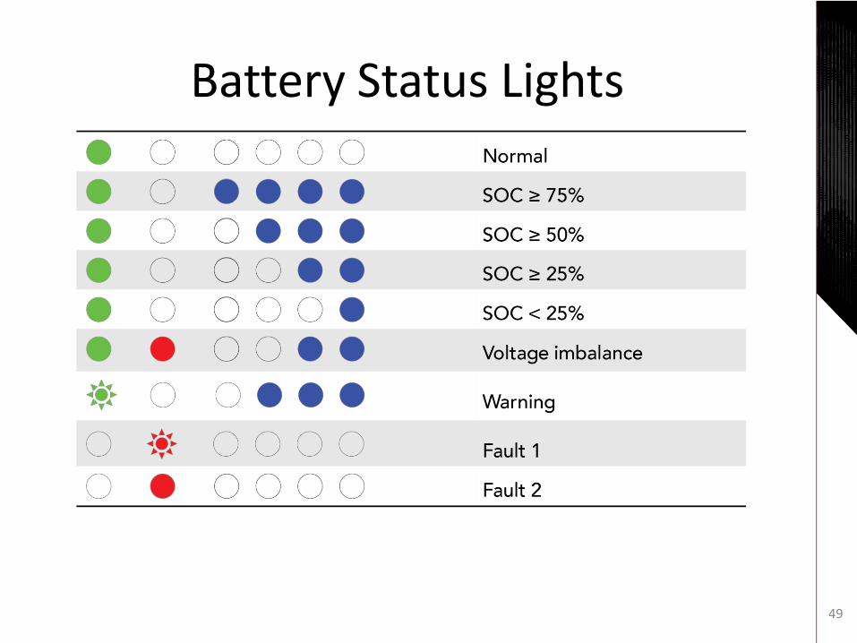
Battery Status Lights
49

Battery Fault Scale
50
Warning: When a battery module is likely to become unstable, it goes into a warning state. This state is cleared when the module recovers its normal condition.
Fault 1: When a battery module is likely to become faulty, it goes into a low level fault state, This state may require an appropriate measure to be cleared.
Fault 2: When a battery module falls outside prescribed limits, it goes into a high level fault state. The battery module in this state is not used anymore. Inspection by LG Chem required.

Select Alerts
51
Too low module voltage
Lost communications between battery modules
Too high battery temperature

See LG Chem Service Manual for complete list of alerts including:
List of Alerts
52
• Cell overvoltage
• Cell undervoltage
• Too low module voltage
• Too large voltage difference between cells
• Over-charged current
• Over-discharged current
• Over-charged power
• Over-discharged power
• Too high battery temperature
• Too low battery temperature
• Too large temperature difference inside battery module
• Lost communication between battery modules
• Lost communication with the inverter
• Too low SOC
• Too high SOC

Completing Installation
Refer to LG Chem installation guide* for:
• Commissioning
• Deactivating
• Troubleshooting
LG Chem Documentation: • https://1drv.ms/f/s!AjpEpD6OS3W3qDybi4Gzu0JiPWdR
• 20171201 - Standalone G2_installation_manual_Final.pdf *
• 170104_Standalone_Specification_V1.1.pdf
• 20171201 - Standalone G2_service_manual_Final.pdf
• JH3 Cell_SDS_LG Chem_AU_R1.1.pdf 53

LG Chem Battery Warranty
• Refer to Warranty Document for complete details of coverage
• Note: a complete download of the battery logging data from the SP Pro inverter is required for any warranty claim
54

Picking List – 5 Battery System
55
Component 5 Battery System Picked
LG Chem EM048126P3Sx 6.5kWh lithium battery modules 3-5 based on order
Communication Cable: Inter-battery 1 per Battery less 1
Communication Cable: First Battery to DB9 Female 1 per System
DC cables (red & black) 1 pair per Battery
Cable Glands – 16mm for data 1
Cable Glands – 28mm for fan controller power 1
Cable Glands – 35mm for DC cable to inverter 2
Cable Glands – 63mm for DC cables from batteries 1
70mm2 cable lugs 2
Temperature control unit for fans with four nuts & bolts 1
Rack Mount Cabinet 22RU to hold up to 5 batteries
Set of four levelling feet for Cabinet 1
Cabinet shelves 5
Nuts & bolts for shelves (4 per shelf) 20
Nuts & bolts for securing modules (4 per module) 20
DC Distribution Board For 5 batteries
Installation manual (this document) 1
Selectronic LG Chem Stand Alone Battery Comms Kit (part no. 005298) 1

Picking List – 10 Battery System
56
Component 10 Battery System Picked
LG Chem EM048126P3Sx 6.5kWh lithium battery modules 5-10 based on order
Communication Cable: Inter-battery 1 per Battery less 1
Communication Cable: First Battery to DB9 Female 1 per System
DC cables (red & black) 1 pair per Battery
Cable Glands – 16mm for data 1
Cable Glands – 28mm for fan controller power 1
Cable Glands – 35mm for DC cable to inverter 2
Cable Glands – 63mm for DC cables from batteries 2
70mm2 cable lugs 2
Temperature control unit for fans with four nuts & bolts 1
Rack Mount Cabinet 37RU to hold up to 10 batteries
Set of four levelling feet for Cabinet 1
Cabinet shelves 10
Nuts & bolts for shelves (4 per shelf) 40
Nuts & bolts for securing modules (4 per module) 40
DC Distribution Board For 10 batteries
Installation manual (this document) 1
Selectronic LG Chem Stand Alone Battery Comms Kit (part no. 005298) 1