literature survey on the stress corrosion cracking of low
TRANSCRIPT

O
ohiQ>
CQ
5)a
P A U L S C H E R R E R I N S T I T U T
CH0200021
PSI Bericht Nr. 02-06February 2002
ISSN 1019-0643
Nuclear Energy and Safety DivisionLaboratory for Materials Behaviour
Literature Survey on the Stress CorrosionCracking of Low-Alloy Steels in High-TemperatureWater
H.P. Seifert
3 3 / 1 3Paul Scherrer InstitutCH - 5232 Villigen PSITelefon 056 310 21 11Telefax 056 310 21 99
Literature Survey on the Stress Corrosion Cracking ofLow-Alloy Steels in High-Temperature Water
H.P. Seifert
Nuclear Energy and Safety DivisionLaboratory for Materials Behaviour
Structural Integrity Group
Abstract
The present report is a summary of a literature survey on the stress corrosion cracking (SCC)behaviour/ mechanisms in low-alloy steels (LAS) in high-temperature water with specialemphasis to primary-pressure-boundary components of boiling water reactors (BWR). Abrief overview on the current state of knowledge concerning SCC of low-alloy reactorpressure vessel and piping steels under BWR conditions is given. After a short introductionon general aspects of SCC, the main influence parameter and available quantitative literaturedata concerning SCC of LAS in high-temperature water are discussed on a phenomenologicalbasis followed by a summary of the most popular SCC models for this corrosion system. TheBWR operating experience and service cracking incidents are discussed with respect to theexisting laboratory data and background knowledge. Finally, the most important openquestions and topics for further experimental investigations are outlined.
TABLE OF CONTENTS
ABSTRACT 2
INDEX 4
0. ABBREVIATIONS 6
1. INTRODUCTION 8
1.1 REPORT OUTLINE 8
1.2 REFERENCES 9
2. GENERAL ASPECTS OF STRESS CORROSION CRACKING 10
2.1 ENVIRONMENTALLY-ASSISTED CRACKING 10
2.2 BASIC ASPECTS AND CHARACTERISTIC FEATURES OF SCC 12
2.3 LABORATORY EAC TEST METHODS AND THEIR RELEVANCE TO LWR COMPONENTS .. 17
3. SCC/SICC OF LOW-ALLOY STEELS IN HIGH-TEMPERATURE WATER 19
3.1 MAIN INFLUENCING FACTORS FOR SCC/SICC 193.2 SCC/SICC SUSCEPTIBILITY CONDITIONS 193.3. ENVIRONMENTAL PARAMETERS 22
3.4 MECHANICAL/LOADING PARAMETERS 30
3.5 MATERIAL PARAMETERS 32
3.6 INCUBATION PERIOD 36
3.7. QUANTITATIVE SCC/SICC CRACK GROWTH RATE DATA 36
4. MECHANISTICAL ASPECTS OF EAC OF LAS 41
4.1 CRACK GROWTH MECHANISMS 41
4.2 LOCAL CRACK-TIP CHEMISTRY AND MASS TRANSPORT 58
4.3 CRACK-TIP ELECTRO- AND WATER CHEMISTRY IN LAS UNDER LWR CONDITIONS 63
4.4 DISCUSSION OF SOME SPECIFIC ASPECTS OF CRACK CHEMISTRY AND EAC 64
5. LWR OPERATING EXPERIENCE AND EAC CRACKING INCIDENTS 74
5.1 EAC CRACKING INCIDENTS IN LWR 74
5.2 OPERATING EXPERIENCE VS. LABORATORY BACKGROUND KNOWLEDGE 78
5.3 POSSIBLE EAC PREVENTION STRATEGIES AND MITIGATION ACTIONS 81
6. OPEN QUESTIONS AND NEEDS FOR FUTURE WORK 83
6.1 CORROSION FATIGUE/ STRAIN-INDUCED CORROSION CRACKING 83
6.2 STRESS CORROSION CRACKING 85
7. EXTENDED SUMMARY AND CONCLUSIONS 87
8. ACKNOWLEDGEMENT 91
9. REFERENCES 92
INDEX
ABSTRACT 2
INDEX 4
0. ABBREVIATIONS 6
1. INTRODUCTION 8
1.1 REPORT OUTLINE 8
1.2 REFERENCES 9
2. GENERAL ASPECTS OF STRESS CORROSION CRACKING 10
2.1 ENVIRONMENTALLY-ASSISTED CRACKING 10
2.1.1 Types of EAC 102.1.2 Classical and Non-Classical SCC 10
2.2 BASIC ASPECTS AND CHARACTERISTIC FEATURES OF SCC 12
2.2.1 SCC Fracture Features 132.2.2 Crack Initiation vs. Crack Growth 132.2.3 SCC Crack Growth Rate vs. Stress Intensity Factor Curves 75
2.3 LABORATORY EAC TEST METHODS AND THEIR RELEVANCE TO LWR COMPONENTS .. 17
3. SCC/SICC OF LOW-ALLOY STEELS IN HIGH-TEMPERATURE WATER.. 19
3.1 MAIN INFLUENCING FACTORS FOR SCC/SICC 193.2 SCC/SICC SUSCEPTIBILITY CONDITIONS 193.3. ENVIRONMENTAL PARAMETERS 22
3.3.1 Temperature 223.3.2 ECP and Oxygen Content 253.3.3 Sulphate Concentration of Environment 273.3.4 Possible Irradiation Effects on EAC 28
3.4 MECHANICAL/LOADING PARAMETERS 30
3.4.1 Critical Strain-rates and Strains 303.4.2 Stress Intensity Factor Threshold for SCC KJSCC 32
3.5 MATERIAL PARAMETERS 32
3.5.1 Steel Sulphur-Content, MnS-Inclusions 323.5.2 Yield Strength Rp, Micro structure 343.5.3 Dynamic Strain Ageing, Free Nitrogen and Carbon Content in Steel 35
3.6 INCUBATION PERIOD 36
3.7. QUANTITATIVE SCC/SICC CRACK GROWTH RATE DATA 363.7.1 SICC Crack Growth Rates 363.7.2 SCC Crack Growth Rates andKiscc 37
3.7.3 Possible Reasons for Data Scatter and High SCC Crack Growth Rates 39
4. MECHANISTICAL ASPECTS OF EAC OF LAS 41
4.1 CRACK GROWTH MECHANISMS 41
4.1.1 Film Rupture / Anodic Dissolution Mechanism (FRAD) 414.1.2 Hydrogen-Assisted EAC (HAEAC) 46
4.1.2.1 Sources of Hydrogen in LAS under LWR Conditions 464.1.2.2 Effects of Hydrogen [see references in 20, 140-144, 160-163] 464.1.2.3 General Aspects of HAEAC in Aqueous Environments 474.1.2.4 HAEAC Model for LAS under LWR Conditions 494.1.2.5 HAEAC vs. FRAD 50
4.1.3 Dynamic Strain Ageing (DSA) 524.1.3.1 Background 524.1.3.2 Phenomenological and Microscopical Features of DSA 524.3.1.3 Physical Metallurgy of DSA 534.1.3.5 Possible Interaction between DSA and EAC in LAS 57
4.2 LOCAL CRACK-TIP CHEMISTRY AND MASS TRANSPORT 58
4.2.1 Basic Concepts of Crack Chemistry in Low-Alloy Steels under LWR Conditions 584.2.2 Differential Aeration Cell at the Crack Mouth 604.2.3 Dissolution Cell at the Crack-Tip 604.2.4 Mass Transport Process in the Crack Enclave 614.2.5 Critical Crack-Tip Sulphur-Anion Concentration for EAC 614.3.6 Critical Crack Growth Rate for EAC 62
4.3 CRACK-TIP ELECTRO- AND WATER CHEMISTRY IN LAS UNDER LWR CONDITIONS 63
4.3.1 Crack-Tip ECP 634.3.2 Crack-Tip pH and Crack-Tip Sulphur-Anion Concentration 634.3.3 Crack-Tip Conductivity 63
4.4 DISCUSSION OF SOME SPECIFIC ASPECTS OF CRACK CHEMISTRY AND EAC 64
4.4.1 ECP and Dissolved Oxygen Content 644.4.2 Impurity Content and Conductivity 644.4.3 Effect of MnS-Inclusions 654.4.4 Asymmetry of Transients and Hysteresis Effects 664.4.5 Effect of Flow Rate 69
5. LWR OPERATING EXPERIENCE AND EAC CRACKING INCIDENTS 74
5.1 EAC CRACKING INCIDENTS IN LWR 74
5.1.1 Common Features of EAC Cracking Incidents 745.1.2 EAC of BWR RPV Feedwater Nozzles 765.1.3 SICC of Thin-Walled Pipings in German BWR 77
5.2 OPERATING EXPERIENCE VS. LABORATORY BACKGROUND KNOWLEDGE 78
5.2.1 Reasons for Higher EAC Cracking Frequency in Laboratory Tests 795.2.2 Reasons for High SCC Cracking Susceptibility in Some Lab Tests 805.2.3 Summary 80
5.3 POSSIBLE EAC PREVENTION STRATEGIES AND MITIGATION ACTIONS 81
5.3.1 Critical Components 825.3.2 Mitigation Actions 82
6. OPEN QUESTIONS AND NEEDS FOR FUTURE WORK 83
6.1 CORROSION FATIGUE/ STRAIN-INDUCED CORROSION CRACKING 83
6.2 STRESS CORROSION CRACKING 85
7. EXTENDED SUMMARY AND CONCLUSIONS 87
8. ACKNOWLEDGEMENT 91
9. REFERENCES 92
0. Abbreviations
ASME
ASME BPV
ASTM
ASTME399
BWR
BWR VIP
C(T)
CERT
CF
CGR
CODLL
DCPD
DO
DSA
EAC
ECP
EPFM
EPRI
FRAD
FW
GÈ
HAEAC
HAZ
HSK
HWC
ICG-EAC
IGSCC
KTA
LAS
LCF
American Society of Mechanical Engineers
ASME Boiler and Pressure Vessel Code
American Society of Testing and Materials
Test Method for Plane-Strain Fracture Toughness of Metallic Materials
Boiling Water Reactor
Boiling Water Reactor Vessel and Internals Project
Compact Tension Specimen
Constant Extension Rate Test
Corrosion Fatigue
Crack Growth Rate
Crack Opening Displacement at Load Line
Direct Current Potential Drop Method
Dissolved Oxygen
Dynamic Strain Ageing
Environmentally-Assisted Cracking
Electrochemical Corrosion Potential
Elastic-Plastic Fracture Mechanics
Electric Power Research Institute
Firm Rupture/Anodic Dissolution Mechanism
Feed Water
General Electric
Hydrogen-Assisted EAC Mechanism
Heat-Affected Zone
Hauptabteilung für die Sicherheit der Kernanlagen
Hydrogen Water Chemistry
International Co-operative Group of Environmentally-Assisted Crackingof LWR Materials
Intergranular SCC
KrThreshold for SCC
Kerntechnischer Ausschuss, Germany
Low-Alloy Steel
Low-Cycle Fatigue

LEFM Linear-Elastic Fracture Mechanics
LFCF Low-Frequency Corrosion Fatigue
LWR Light Water Reactor
LWV Labor fur Werkstoffverhalten
MPA Staatliche Materialprufungsanstalt, University of Stuttgart, Germany
NDT Non-Destructive Testing
NRC National Regulatory Commission, USA
NWC Normal Water Chemistry
PEER Panel of Experts for Evaluation and Review
PWHT Post-Weld Heat Treatment
PWR Pressurized Water Reactor
QA Quality Assurance
RPV Reactor Pressure Vessel
SCC Stress Corrosion Cracking
SEM Scanning Electron Microscopy
SHE Standard-Hydrogen-Electrode
SICC Strain-Induced Corrosion Cracking
SRL Slow Rising Load Test
SS Stainless Steel
SSRT Slow Strain Rate Test
SSY Small Scale Yielding
TGSCC Transgranular SCC
UTS Ultimate Tensile Strength
VGB Technische Vereinigung der Grosskraftwerksbetreiber, Deutschland
YS Yield Strength

1. IntroductionThe reactor pressure vessel (RPV) of both boiling water (BWR) and pressurized waterreactors (PWR) is the most critical pressure-boundary component as far as safety and plantlife are concerned [1.1, 1.2]. The high standards of safety and reliability on this pressure-boundary component in light water rectors (LWR) require that all potential relevant ageingand degradation mechanism affecting structural integrity are sufficiently understood so thateven low probability failures can be ruled out by adequate (counter)measures. RPV structuralintegrity continues therefore to be a key concern within the context of both reactor safety andevaluation/extension of plant service life.
In the past, RPV ageing and degradation have been mainly discussed with respect toirradiation embrittlement and to thermal/mechanical fatigue. Both ageing mechanism havealready been anticipated during the design phase and have been implemented to the nuclearcodes and regulations (ASME BPV, KTA). They are controlled by suitable surveillanceprogrammes and fatigue evaluation procedures. On the other hand, the possible effect ofcorrosion phenomena on RPV structural integrity has been ignored for many years.Environmental effects have therefore not been directly addressed in the guidelines forassessing both the initiation of fatigue cracks and the fatigue crack growth behaviour in therelevant nuclear codes (ASME DI, XI). Early laboratory investigations clearly demonstratedthat environmentally-assisted cracking (EAC) might occur in RPV steels in high-temperaturewater under certain critical system conditions. Based on these investigations the question onconservatism and adequacy of the relevant nuclear codes was arising and has resulted inintensive experimental and theoretical investigations on EAC during the last two decades.
Notwithstanding the absence of stress corrosion cracking (SCC) in the field, SCC has beenobserved in laboratory tests under simulated BWR conditions with crack growth rates rangingfrom 30 urn/year to 3 m/year even under nominally similar testing conditions. The SCCbehaviour of low-alloy RPV steels in oxygenated high-temperature water and its possiblerelevance to BWR power operation has therefore been a subject of controversial discussions.There seemed to be a crucial discrepancy between the existing laboratory SCC crack growthdata base and the excellent operating experience. With regard to the current BWR operatingpractice, it was not evident if an unacceptably high risk or potential for sustained growth ofcracks in reactor pressure vessel steels by SCC actually existed or not. A large experimentaland theoretical research programme on SCC of low-alloy RPV steels under BWR conditionswas therefore initiated at PSI (SpRK II, 1996 - 1999). The working programme of thisresearch project included:
a literature survey on SCC of low-alloy RPV steels (this report).
an experimental parameter study to characterise the SCC susceptibility of low-alloyRPV steels under BWR conditions [1.1, 1.2].
- the participation in an European Round Robin test programme [1.3, 1.4].
a survey and assessment of SCC mechanism and models for low-alloy steels in high-temperature water and the development of a quantitative SCC model [1.5, 1.6].
1.1 Report outlineThe present report is a summary of the literature survey on the SCC of low-alloy steels inhigh-temperature water performed at the beginning of this research programme. The surveyroughly reflects the state-of-the art until the end of 1998 but also includes the results of someselected, newer papers on that topic. The report is divided into six individual sections:
After a short introduction on general aspects of SCC in metals (Section 2), the main influenceparameters and available quantitative literature data concerning SCC of LAS in high-temperature water are discussed on a phenomenological basis (Section 3). In Section 4, asummary on the most popular SCC models for this corrosion system is given. The importantrole of crack-tip strain-rate and crack-tip sulphur-anion activity for SCC in LAS is outlined.The BWR operating experience and service cracking incidents are discussed with respect tothe existing laboratory data and the mechanistical background knowledge (Section 5). Themost important open questions and possible topics for future work are outlined in Section 6followed by an extended summary of the literature survey (Section 7).
1.2 References
[1.1] J. Heldt, H.P. Seifert, ,,Stress corrosion cracking of low-alloy reactor-pressure-vesselsteels in oxygenated, high-temperature water", Nuclear Engineering & Design, Vol. 206,2001, pp. 57 -89 .
[1.2] H.P. Seifert, J. Heldt, U. Ineichen, U. Tschanz, ,,Spannungsrisskorrosion von Stahlenfur Reaktorkomponenten in Heisswasser", BFE-Final Report, February 2000, 41 p.
[1.3] A. Wunsche, D. Blind, F. Huttner (MPA Stuttgart), K. Kiister (HEW), P.Karjalainen-Roikonen, U. Ehrnsten (VTT), A. Roth (Siemens KWU), H.P. Seifert,J. Heldt (PSI), ,,European round robin test on EAC of LAS under BWR conditions",Final Report, MPA Stuttgart, March 2000.
[1.4] A. Wunsche, D. Blind, F. Huttner (MPA Stuttgart), K. Kuster (HEW), P. Kar-jalainen-Roikonen, U. Ehrnsten (VTT), A. Roth (Siemens KWU), H.P. Seifert, J.Heldt (PSI), ,,European round robin test on EAC of LAS under BWR conditions", Proc.9th Int. Symp. on Environmental Degradation of Materials in Nuclear Power Systems -Water Reactors, ANS/NACE/TMS, 1.-5. August 1999, Newport Beach, CA, USA, Eds:S. Bruemmer, P. Ford, G. Was, pp. 911 - 919.
[1.5] B. Tirbonod, ,,Modelling of the stress corrosion cracking behaviour for low-alloy steelsin high-temperature water ", PSI-Report Nr. 00-08, November 2000, ISSN 1019-0643.
[1.6] B. Tirbonod, ,,Stress corrosion cracking behaviour of low-alloy steels in high-temperature water: description and results from modelling", PSI Annual Scientific Report2000, Volume IV, Nuclear Energy and Safety, ISSN 1423-7334, March 2001, pp. 105 -114.

2. General Aspects of Stress Corrosion Cracking
2.1 Environmentally-Assisted Cracking
EAC is an important environmental degradation mechanism, which covers both the initiationand sub-critical growth of cracks under the simultaneous and synergistic interaction ofmechanical stress and a ,,chemically active" environment.
2.1.1 Types of EAC
On the basis of the applied, external, mechanical load, three different types of EAC can bedifferentiated (Table 1).
Mechanism
Type of loading
LWR operationcondition
Quantitativecharacterisation
secStress Corrosion
Cracking
static
steady-statepower operation
BWR VIP 60disposition lines
EAC
SICCStrain-Induced
Corrosion Cracking
slow monotonically risingor very low-cycle (vLCF)
start-up/shut-downthermal stratification
-
CFCorrosion Fatigue
cycliclow-cycle high-cycle
thermal fatiguethermal stratification
ASME m and XI
Table 1: Basic types of EAC. For the RPV, the basic EAC types can be assigned to differentLWR operating conditions.
Almost every alloy/environment system is susceptible to CF, in contrast to SCC, which isvery specific to certain combinations of alloy/environment/ material state ("criticalconditions"). In SCC, the crack path can be either trans- or intergranular, whereas in CF, it isgenerally transgranular in nature. In contrast to CF, distinct limiting or threshold conditionsconcerning solution concentration, temperature and potential exist for SCC [1,2].
2.1.2 Classical and Non-Classical SCC
SCC can be further classified by the crack propagation mechanism, crack path, etc. Because ofits relevance for practical applications, the differentiation of SCC systems by their strain-ratedependence is further worked out here. In classical corrosion systems (type I SCC) SCC crackinitiation (and subsequent growth) can occur if the strain-rate is virtually zero (or sometimeseven negative). In non-classical systems (Type II SCC, strain-rate-sensitive SCC) SCC initiationonly occurs, if a positive strain-rate e > 0 occurs (see Table 2 and Figure 1) [1, 2]. For bothtypes, corrosion-assisted cracking only occurs, if the applied strain-rates are within a "criticalrange", limited by the upper (e 0 and lower (£2) bound critical strain-rates (see Figure 1 and 2).At high strain-rates, mechanical processes leading to fracture occur faster than e.g.electrochemical reactions or corrosion-deformation interactions. Therefore mechanical fracturetakes place without any relevant influence of the corrosive environment. At very low strain-rates, mechanical processes are not sufficiently effective to cause EAC in Type II SCC [1,2].
The concept of Type I and Type II was originally applied for SCC tests with smooth tensilespecimens, but it can be also transferred to notched or pre-cracked specimens or even to
10
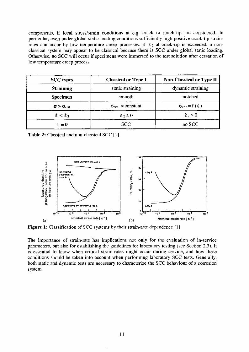
components, if local stress/strain conditions at e.g. crack or notch-tip are considered. Inparticular, even under global static loading conditions sufficiently high positive crack-tip strain-rates can occur by low temperature creep processes. If £2 at crack-tip is exceeded, a non-classical system may appear to be classical because there is SCC under global static loading.Otherwise, no SCC will occur if specimens were immersed to the test solution after cessation oflow temperature creep process.
SCC types
Straining
Specimen
CJ > Ocrit
e < ei
e = 0
Classical or Type I
static straining
smooth
Gcrit ~ constant
£ 2 < 0
SCC
Non-Classical or Type II
dynamic straining
notched
Ocrit = f (£)
£ 2 > 0
no SCC
Table 2: Classical and non-classical SCC [1].
lis
Pi3 ,-" Om © 2
2
inert environment A I. 8
I ! I j I10-10
Nominal strain rate (s'1 ]t~\ ,.«,„„.«,>.„•„„,»«,<» , ,, Nominal strain rate [ s 1 )
Figure 1: Classification of SCC systems by their strain-rate dependence [1]
The importance of strain-rate has implications not only for the evaluation of in-serviceparameters, but also for establishing the guidelines for laboratory testing (see Section 2.3). Itis essential to know when critical strain-rates might occur during service, and how theseconditions should be taken into account when performing laboratory SCC tests. Generally,both static and dynamic tests are necessary to characterize the SCC behaviour of a corrosionsystem.
11

CM
ctiQ_
o
inert environment
"Type II
. TyPe
KISCC
aggressive environment
KId
10-8 10L 10a
1/2,Loading rate dK/dt [MPa-m/s]
Figure 2: Classification of SCC systems by their dKj/dt-dependence [3, 4].
2.2 Basic Aspects and Characteristic Features of SCC
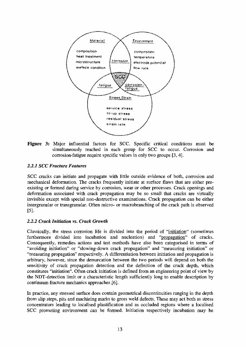
SCC can be defined as the initiation and subcritical growth of cracks under the simultaneoussynergistic interaction of approximately constant mechanical tensile stresses and a chemicallyactive environment [3, 4]. In addition to this, the material often has to be in a susceptiblemicrostructural state. There are always specific couples of alloy and environment establishingSCC under adequate mechanical loading conditions (Figure 3), while the stresses required tocause SCC may be rather small, usually below the macroscopic yield stress, and are tensile innature [5].
Generally distinct environmental (temperature, solution concentration and potential) andloading (stress, strain-rate) limits and thresholds for the occurrence of SCC do exist. Suchthresholds and limits are system parameters, in the sense that their values depend on eachother and are generally only valuable in a limited range of the parameter space of thecorrosion system.
12
compositionN«at treatmentmicros Iructure etecSrode potentialsurface condition
stressfit-up stressresidua? slr«ssstraw rate
Figure 3: Major influential factors for SCC. Specific critical conditions must besimultaneously reached in each group for SCC to occur. Corrosion andcorrosion-fatigue require specific values in only two groups [3, 4].
2.2.1 SCC Fracture Features
SCC cracks can initiate and propagate with little outside evidence of both, corrosion andmechanical deformation. The cracks frequently initiate at surface flaws that are either pre-existing or formed during service by corrosion, wear or other processes. Crack openings anddeformation associated with crack propagation may be so small that cracks are virtuallyinvisible except with special non-destructive examinations. Crack propagation can be eitherintergranular or transgranular. Often micro- or macrobranching of the crack path is observed[5].
2.2.2 Crack Initiation vs. Crack Growth
Classically, the stress corrosion life is divided into the period of "initiation" (sometimesfurthermore divided into incubation and nucleation) and "propagation" of cracks.Consequently, remedies actions and test methods have also been categorised in terms of"avoiding initiation" or "slowing-down crack propagation" and "measuring initiation" or"measuring propagation" respectively. A differentiation between initiation and propagation isarbitrary, however, since the demarcation between the two periods will depend on both thesensitivity of crack propagation detection and the definition of the crack depth, whichconstitutes "initiation". Often crack initiation is defined from an engineering point of view bythe NDT-detection limit or a characteristic length sufficiently long to enable description bycontinuum fracture mechanics approaches [6].
In practice, any stressed surface does contain geometrical discontinuities ranging in the depthfrom slip steps, pits and machining marks to gross weld defects. These may act both as stressconcentrators leading to localised plastification and as occluded regions where a localisedSCC promoting environment can be formed. Initiation respectively incubation may be
13
defined as the very time required to form a localised environment (by stress-independentcorrosion processes) that is conducive to subsequent crack propagation. This initiationprocess can relatively rapidly occur if compared to LWR-design lives of 30 to 40 years.However, the subsequent SCC propagation rates under LWR conditions can be very slow andin this case, SCC crack propagation may determine the component life time. On the contrary,in aggressive environments e.g. found in chemical industry fast SCC crack growth can occurbut the crack initiation period often exceeds the design lifetime of the component. Suchcomponents would not be used in practice, if an analysis would solely be based on fracturemechanics SCC tests taking the growth of pre-existing cracks into account only [6].
Otherwise, by a fracture mechanics approach the crack initiation period is often regarded asan additional safety margin. The high stress concentration at sharp fatigue pre-cracks isleading to significant local crack-tip plasticity and the restricted crack geometry favours theformation of an aggressive occluded water chemistry. Here, conditions for crack initiationappear to be more favourable than that at smooth ,,defect-free" surfaces. Thus, tests with pre-cracked specimens are sometimes regarded as extremely conservative with respect topractice, even if in these tests long incubation periods are sometimes observed (especially inthe case of intergranular SCC where long periods can be necessary for the transition from thetransgranular fatigue pre-crack to the intergranular SCC crack).
The most common SCC/SICC mitigation strategy is to exclude large pre-existing defects byadequate NDT and QA measures during and after fabrication of components before they wereput in operation and to avoid during operation those conditions, which could lead to crackinitiation. Nevertheless, cracking in operating components may be induced by transient orfaulted operation conditions during service or may be detected by ND-inspection. Thereforeadditional investigations on the SCC crack propagation behaviour are necessary and essentialfor both safety and structural integrity assessments and to set-up ND inspection intervals,especially for safety-relevant components of LWR.
The factors controlling crack initiation and growth may significantly differ. Therefore bothprocesses may show relevantly different responses to changes in the corrosion system.
Crack initiation is a complex sequence of different stochastic and deterministic microscopicprocesses and events which often include pit initiation, pit growth, multiple micro-crackinitiation at pit ground, micro-crack coalescence and growth of a main-crack. Only the laststep can be described by LEFM if the main-crack is long enough. Furthermore crackinitiation is strongly affected by the surface state, a factor which is strongly dependent onfabrication process of the component. Parameters describing SCC/SICC crack initiation aretherefore often subjected to a statistical distribution and to a large scatter. Therefore crackinitiation is difficult to handle [5].
Crack growth is also based on a complex sequence of several individual steps (Figure 4).Each of these steps can depend in a different manner on the other system parameters and maybe rate-limiting. A change of the system conditions can cause a change in the rate-limitingstep, which can produce a significantly different behaviour [5].
14

Figure 4: Schematic of crack-tip processes that may be the rate-determining step for SCCpropagation. Factors that affect the rate-determining step have the strongest effecton crack propagation. If corrosion system parameters are modified, the rate-determining step and response to the corrosion system parameter can change [5].
2.2.3 SCC Crack Growth Rate vs. Stress Intensity Factor Curves
Most frequently, the SCC propagation behaviour is quantitatively characterised by tests withpre-cracked fracture mechanic specimens. Mode I loading is generally used, because it ismost severe for SCC and results in lowest thresholds [5]. Tests under slow monotonicallyrising load with different loading rates are necessary to derive minimum Kiscc values for typeII SCC (see Figure 2). Under constant load the stress intensity factor is increasing withincreasing crack length, whereas it decreases under constant deformation. Crack growth ratevs. stress intensity factor diagrams are derived from several individual tests (see Figure 5).Such tests have to be performed either under conditions where LEFM is valid (SSY-conditions) or EPFM parameters as J have to be used to characterise mechanical crack-tipconditions.
15
t%
8/
/tijiii
MACROBRANCHING /
POSSIBLE /
POSSIBLE /
p B /
Kg 5: 1.4 Kp ;
•
INTENSITY,
iscc
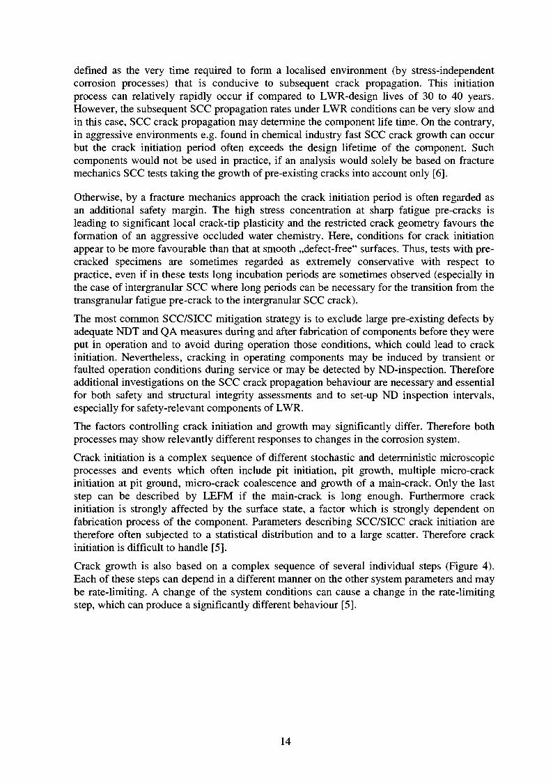
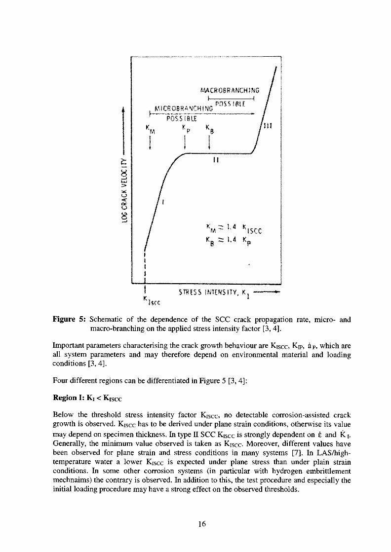
Figure 5: Schematic of the dependence of the SCC crack propagation rate, micro- andmacro-branching on the applied stress intensity factor [3, 4].
Important parameters characterising the crack growth behaviour are Kiscc* Kn>, aP, which areall system parameters and may therefore depend on environmental material and loadingconditions [3, 4].
Four different regions can be differentiated in Figure 5 [3, 4]:
Region I: Ki < Kiscc
Below the threshold stress intensity factor Kiscc, no detectable corrosion-assisted crackgrowth is observed. Kiscc has to be derived under plane strain conditions, otherwise its valuemay depend on specimen thickness. In type II SCC Kiscc is strongly dependent on e and K i.Generally, the minimum value observed is taken as Kiscc- Moreover, different values havebeen observed for plane strain and stress conditions in many systems [7]. In LAS/high-temperature water a lower Kiscc is expected under plane stress than under plain strainconditions. In some other corrosion systems (in particular with hydrogen embrittlementmechnaims) the contrary is observed. In addition to this, the test procedure and especially theinitial loading procedure may have a strong effect on the observed thresholds.
16
Region II: KJSCC ^ Ki < Kn>
In this region crack growth rate increases with increasing stress intensity factor, often with apower law function (a = A -Kin). In some corrosion systems a direct transition from region Ito III is observed within a very small stress intensity range. Above = V2 • Kiscc micro-branching may be observed.
Region III: Kn» < Ki < KiC:
In this region crack growth rate is not or just slightly dependent on the stress intensity factor.It is often considered that mass transport controls crack growth in this region. Above ~ \ 2 •Kn> macro-branching may be observed.
Region IV: Ki > KIC or Ku
If Ki reaches Kic or KIJ sudden catastrophic failure or onset of pure ductile mechanical crackgrowth without any relevant environmental effect occurs.
2.3 Laboratory EAC Test Methods and Their Relevance to LWR Components
The thermo-mechanical loading conditions of operating LWR pressure-boundary componentsare very complex; the corresponding load spectrum is a complex superposition and/orsequence of different loading modes (static, cyclic). Therefore, in laboratory tests a widerange of loading (static, dynamic, cyclic) and environmental conditions reflecting thedifferent operating conditions (start-up/shut-down, steady-state power operation, stand-by,transients, ...) are necessary to reliably evaluate and assess the possible effect of EAC on thelong-term structural integrity of low-alloy pressure-boundary components in LWR. Differenttypes of specimen (smooth, notched, pre-cracked) are necessary to characterize the EACinitiation and growth behaviour.Dynamic SCC tests cannot clearly differentiate between Type I and Type II SCC. On theother hand pure static tests can feign a high stability against SCC/SICC if the system issusceptible to Type II SCC or if exposure time is too short with respect to typical incubationperiods for Type I SCC. In Figure 6 an hierarchy of SCC test methods is given [8], whichallows an efficient and rational screening for SCC/SICC susceptibility in a givenalloy/environment system.In Figure 7 an overview on typical EAC test methods and their relevance to LWRcomponents is given [9]. Consequently, the component behaviour under operating conditionscan only be assessed if several of the presented test methods were deliberately combined.
17

ABBREVIATIONS:
SSBT SLOW STRAIN RATE TSSTS
i ESSRT ELASTiC SLOW STRAIN RATS
TESTS
ISSRT !NTERRUS»TED SLOW STRAIN KATETESTS
Figure 6: Hierarchy of SCC test methods [8].
Figure 7: EAC test methods and their relevance to LWR components [9].
18

3. SCC/SICC of Low-Alloy Steels in High-Temperature Water
The SCC/SICC susceptibility and propagation of low-alloy pressure-boundary componentsteels in oxygenated high-temperature water is governed by a complex system of interrelatedand svnergistic factors, such as material, environmental and loading parameters, by design,manufacturing, process and operating related features. The sum of these features arecharacterising the corrosion system. SCC/SICC initiation and growth are only observed underspecific combinations of environmental, loading and material conditions. Crack initiation andgrowth may be controlled by different microscopic processes and may therefore show adifferent response to the various system parameters. The term SCC/SICC susceptibility isrelated to crack initiation in this report, if not further specified.
3.1 Main Influencing Factors for SCC/SICC
The following main influencing factors for SCC/SICC have been identified during the lastdecades [11-27]:
• Environmental parameters:
- corrosion potential ECP
ECP = f(C<2, H2O2, H2, pH, T, flow rate, impurities, chemical compositionof alloy (Cr, Ni,...), history, exposure time,...)
- temperature T
- concentration of specific (anionic) impurities: SO42", Cl\ HS", S2\ H2S,...
- flow rate
• Material parameters:
- sulphur content
- morphology, size, spatial distribution and chemical composition of MnS-inclusions
- free nitrogen and carbon content (DS A response of alloy)—> nitrogen/aluminium-ratio, PWHT- or annealing-temperature
• Loading parameters:
- loading or strain-rate: dKi/dt, de/dt
- load, stress or strain level: Ki, o, e
3.2 SCC/SICC Susceptibility ConditionsIt is known from both experimental and field experience that EAC may occur in low-alloypressure-boundary component steels in oxygenated, high-temperature water if the followingconditions are simultaneously attained:
- Corrosion potential: ECP > ECPcrit = -200 mVSHE (if K < 0.3 |0,S/cm)
- Strain-rate: 0 <ecrit,min < e < £criunax= 10"1 %/s
- Strain: e > E ^ = 0.1 - 0.3 % > elastic limit (ocrit > Rp)
In particular, slow, positive, dynamic tensile straining with associated plastic yielding appearsto be essential for EAC initiation and growth. The extent of EAC cracking is crucially
19
dependent both on maintaining a positive crack-tip strain-rate and a high sulphur-anionactivity in the crack-tip environment. Hence, high EAC crack growth rates (CGR) areobserved in steels with a high MnS-inclusion content in highly oxidising environments withhigh impurity level in the water and, in particular, under dynamic loading conditions.
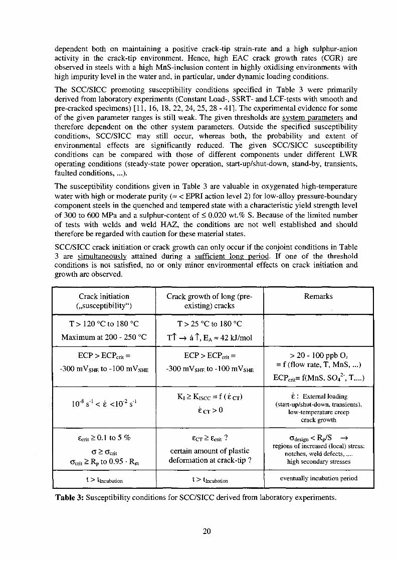
The SCC/SICC promoting susceptibility conditions specified in Table 3 were primarilyderived from laboratory experiments (Constant Load-, SSRT- and LCF-tests with smooth andpre-cracked specimens) [11, 16, 18, 22, 24, 25, 28 - 41]. The experimental evidence for someof the given parameter ranges is still weak. The given thresholds are system parameters andtherefore dependent on the other system parameters. Outside the specified susceptibilityconditions, SCC/SICC may still occur, whereas both, the probability and extent ofenvironmental effects are significantly reduced. The given SCC/SICC susceptibilityconditions can be compared with those of different components under different LWRoperating conditions (steady-state power operation, start-up/shut-down, stand-by, transients,faulted conditions,...).
The susceptibility conditions given in Table 3 are valuable in oxygenated high-temperaturewater with high or moderate purity (= < EPRI action level 2) for low-alloy pressure-boundarycomponent steels in the quenched and tempered state with a characteristic yield strength levelof 300 to 600 MPa and a sulphur-content of < 0.020 wt.% S. Because of the limited numberof tests with welds and weld HAZ, the conditions are not well established and shouldtherefore be regarded with caution for these material states.
SCC/SICC crack initiation or crack growth can only occur if the conjoint conditions in Table3 are simultaneously attained during a sufficient long period. If one of the thresholdconditions is not satisfied, no or only minor environmental effects on crack initiation andgrowth are observed.
Crack initiation(,,susceptibility")
T>120°Ctol80°C
Maximum at 200 - 250 °C
ECP > ECPcnt =
-300 mVsHE to -100 mVSHE
10"8 s-1 < e <10"2 sA
8crit^0.1 to 5 %
CJ > Ccrit
Cent > RP to 0.95 • Rm
t > tincubation
Crack growth of long (pre-existing) cracks
T > 25 °C to 180 °C
Tt-> at,EA = 42kJ/mol
ECP > ECPcrit =
-300 mVsHE to -100 mVSHE
Ki > Kiscc = f (e CT)
£ C T > 0
£CT ^ Ecrit ?
certain amount of plasticdeformation at crack-tip ?
t > tincubation
Remarks
> 2 0 - 100ppbO2
= f (flow rate, T, MnS,...)
ECPcrit= f(MnS, SO42\ T,...)
£ : External loading(start-up/shut-down, transients),
low-temperature creepcrack growth
^design < Rp/S ->regions of increased (local) stress:
notches, weld defects,....high secondary stresses
eventually incubation period
Table 3: Susceptibility conditions for SCC/SICC derived from laboratory experiments.
20
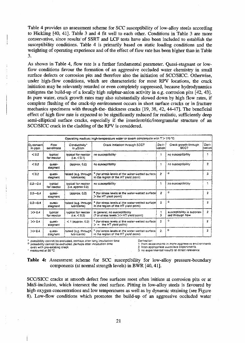
Table 4 provides an assessment scheme for SCC susceptibility of low-alloy steels accordingto Hickling [40, 41]. Table 3 and 4 fit well to each other. Conditions in Table 3 are moreconservative, since results" of SSRT and LCF tests have also been included to establish thesusceptibility conditions. Table 4 is primarily based on static loading conditions and theweighting of operating experience and of the effect of flow rate has been higher than in Table3.
As shown in Table 4, flow rate is a further fundamental parameter. Quasi-stagnant or low-flow conditions favour the formation of an aggressive occluded water chemistry in smallsurface defects or corrosion pits and therefore also the initiation of SCC/SICC. Otherwise,under high-flow conditions, which are characteristic for most RPV locations, the crackinitiation may be relevantly retarded or even completely suppressed, because hydrodynamicsmitigates the build-up of a locally high sulphur-anion activity in e.g. corrosion pits [42, 43].In pure water, crack growth rates may also substantially slowed down by high flow rates, ifcomplete flushing of the crack-tip environment occurs in short surface cracks or in fracturemechanics specimens with through-the- thickness cracks [19, 38, 42, 44-47]. The beneficialeffect of high flow rate is expected to be significantly reduced for realistic, sufficiently deepsemi-elliptical surface cracks, especially if the interdentritic/intergranular structure of anSCC/SICC crack in the cladding of the RPV is considered.
Operating medium: higMemperatufe water or steam eonssnsats with T > 1?O °C
O} contentin.pprc
<Q2.
<0.2
<Q.S
0.2—0.4
0.2—0.4
»0.A
Flow j Conductivity*conditions j ift j»S/em
typicalfor reactor
quasi-stagnant
quasi-stagnant
typicaliOf rsattor
quasi-stagnant
Quasi-stagnant
typicaltef reactor
typical for reactor(i.e. < 0.1}
(apprsx. 0,2}
raised (e.g. throughlubricants)
typical for reactor{i.e. appro* 0.2)
(appro*. 0.2}
raised (e.g. threugftlubricanis}
typical to? reactor{i.e. < 0.2)
»0.4 I qussi- ! < 1 (approx. 0.2)i stagnant j
»0.4 quasi- iraised Ce.g. throughstagnant | lubricants)
' •
Crack initiation through SCC?
no susceptibility
no susceptibility
* {for stress levels at the water-wetted surfaceSrs the region of the HT yield point}
no susceptibility
* (tor stress levels at She vuster-wetted surface>tr»e HT yield point)
* (for stress tevete at trse waier-wetseo* surfacein the region csf the HT yieStJ point)
in general, no susceptibility(? af stress levess » HTyield point)
* {for stress levels at ine wate.'.we«e<J surface> « the HT yield point)
* ifer ssress Severn at tn« wmef-wettad surfapsin the region ef the HT yield point)
Deri-vation
1
1
2
Crack growth throughSCC?
no suscepH&Mity
no susceptibility
<s
1 j r<o susceptibilityI
2
3
2
2
0
0
susceptibility is suppres-sed througft Sow
Deri-vation
2
3
1
2
a
2
° 1 2
0 2
x possibility cannot be excludes, perhaps aHer long incubtatiori time° possibility oanrsoi be excludstf. perhaps sfser incubation time
ev-en with pre~existms crack• measured at 2S "C
1 from experiments in more aggressive env;ro2 from appropriate ausociave experiments3 no expefime^tai results o1 direc? relevance
Table 4: Assessment scheme for SCC susceptibility for low-alloy pressure-boundarycomponents (at normal strength levels) in BWR [40,41].
SCC/SICC cracks at smooth defect free surfaces most often initiate at corrosion pits or atMnS-inclusion, which intersect the steel surface. Pitting in low-alloy steels is favoured byhigh oxygen concentrations and low temperatures as well as by dynamic straining (see Figure8). Low-flow conditions which promotes the build-up of an aggressive occluded water
21

chemistry in these small surfaces defects strongly favours SCC/SICC initiation at the pitground.
300
200
100
1000 !0QC0
ers content lpt}ll)
Figure 8: Effect of DO, temperature and strain-rate on pitting in LAS [32].
In the following sections some important phenomenological aspects are further worked out.Most influencing parameters are interrelated and synergistic, and therefore cannot bediscussed independently. In many cases, the effect of system parameters on the crackinitiation and crack growth process cannot be clearly separated. Therefore, both aspects aregenerally discussed together. Most system parameters have not yet been systematicallystudied. The analysis of the effect of different system parameters based on experimentalstudies of different authors with significant variabihty in system conditions from study tostudy and test to test, is therefore associated with uncertainty.
3 3 . Environmental Parameters
3.3.1 Temperature
The effect of temperature on SCC/SICC initiation and growth has not yet been systematicallystudied. There are only a few crack growth investigations in high-purity water and most ofthem have been performed in the temperature range of 270 to 300 °C. Temperature effectsshould be studied under constant process conditions. Because of significant variations inECP, steel sulphur content and mechanical loading conditions, comparison of literature datais difficult and no satisfactory conclusion on temperature effects can be derived from thesetests. Furthermore, in most cases it is often difficult to clearly separate the effect oftemperature on crack growth from its effect on the thresholds for the onset of EAC.Therefore, the effect of temperature on crack initiation and crack growth is not yet fullyunderstood.
The SCC/SICC susceptibility of low-alloy pressure-boundary component steels seems to below below 100 °C, but the few tests at low temperatures indicate that EAC may still occur[15, 67, 99]. From SSRT tests with smooth tensile specimens, a maximum susceptibility can
22

be derived between (150 °C) 200 °C and 250 °C (see Figure 9) [11, 19, 33, 49, 98, 99],depending on dissolved oxygen content and sulphur content of the steel. A minimum oxygenconcentration is needed in this temperature range to exceed the ECPcrjt [44, 49]. Dynamicstrain ageing (DSA) (and free nitrogen and carbon content of the steel) may be a furthercontributing factor for this maximum of susceptibility and for variations in temperature trendsbetween different alloys [27]. In LCF-tests, fatigue life (which is defined as the number ofcycles required to form an engineering-size crack form a "defect-free surface", e.g. 3 nun-deep crack) decreases linearly with temperature above 150 °C and up to 320 °C [36, 71],when the other threshold conditions for environmental effects are satisfied. Fatigue life isinsensitive to temperatures below 150 °C or when any other threshold condition is notsatisfied [36, 71]. The temperature effects may depend on factors such as DO, ECP, strain-rate, strain, and steel sulphur content [36]. It is generally believed that the decrease in fatiguelife is caused primarily by the effects of environment on the growth of short cracks that are< 100 nm [101]. Nevertheless, the temperature effect in both test types (LCF, SSRT) oninitiation and propagation cannot be clearly separated.
<ex
80
70
50
40
%o
20
• Alloy B (0.004 yvt.%S, 0.013 wt.%AI) ;• Alloy D (0.018 Wt.%S, 0.03 wt.%AI) ;
Open symbols: \o SICC detected by CpPD (K,™)
n;o
100 150 200 250 300 350
150 250 358 *C Temperature [°C]
Figure 9: Maximum SICC susceptibility at intermediate temperatures in SSRT tests [11]with smooth specimens and slow rising load tests with pre-cracked specimens[29].
The SCC crack growth rate seems to decrease with decreasing temperature [15, 21] (seeFigure 10). An activation energy of 42 KJ/mol has been determined with plateau-crackgrowth rates under aggressive environmental (high impurity content, highly oxidising) andextremely loading conditions (outside LEFM) with pre-cracked specimens under staticloading in static autoclaves [15, 21]. This activation energy can be taken as a rough estimateof corresponding crack growth rates at different temperatures. In high-purity water, there isalmost no susceptibility to sustained SCC growth [28, 29], making it impossible to determineactivation energies and temperature trends under these conditions. In SSRT tests inoxygenated high-temperature water, increasing SICC CGR were observed with increasingtemperatures between 150 °C and 288 °C [11, 33, 97, 98].
23

-j 288
• temperature
16O SOQ
10
soa22O
2.0 o rf^c]
\
«.« 2.0 2,4 2
reciprocai tempsrature, 1/T, i 1/K * 10
M 3.8 4.0
a] reciprocal temperature 1/T [1/J€«10i
Figure 10: Temperature dependence of SCC crack growth rates [15,41].
The situation is even more complex under cyclic loading conditions (corrosion fatigue),where depending on loading conditions (frequency/strain-rate, load amplitude and R-value),crack growth rates between 150 °C and 300 °C were either monotonically increasing withtemperature or showing a maximum at intermediate temperatures between 180 ° to 240 °C[14, 38, 72 - 84] (see Figure 11). In some cases even a minimum at intermediate temperaturewas reported [75, 78]. Thresholds and crack growth rates may show different temperaturetrends. It has been proposed, that both plateau thresholds and plateau CGR in corrosionfatigue increase with increasing temperature [72]. The region of EAC might therefore besignificantly extended at lower temperatures compared to 290 °C.
IE-OS0.001 6.&1 0.1 1 10
CYCLIC FREQUENCY, Hz
Figure 11: Effect of loading frequency and temperature on CF CGR [84]. 2E-4 Hz:Maximum at 250 °C. 5E-2 Hz: CF CGR monotonically increases withtemperature.
24

Within certain limits, there is a trend, that EAC CGR increase with increasing temperaturesfor given fixed testing conditions. DSA and the temperature dependence of different EACthresholds (AKpi, strain-rate,...) are probably the two major reasons for deviations form thistrend and for a more complex behaviour. A change in crack growth mechanism (FRAD toHAEAC, true CF to stress corrosion fatigue) may be further contributing factors. DSA mayexplain a CGR maximum at intermediate temperature for certain strain-rates by both its effecton CGR and on thresholds. Differences in the free nitrogen and carbon content of the steelmay explain the quite different temperature response sometimes observed of otherwisesimilar alloys. A lower plateau thershold AKpi in corrosion fatigue at lower temperatures mayexplain a negative temperature dependence of EAC in the case where the AK of the tests doesexceed the threshold AKpi at lower temperatures, but not at higher temperatures. There areseveral experimental indications that the range of environmental, material and loadingconditions leading to EAC may significantly extended at intermediate and low temperaturescompared to tests at 290 °C.
3.3.2 ECP and Oxygen Content
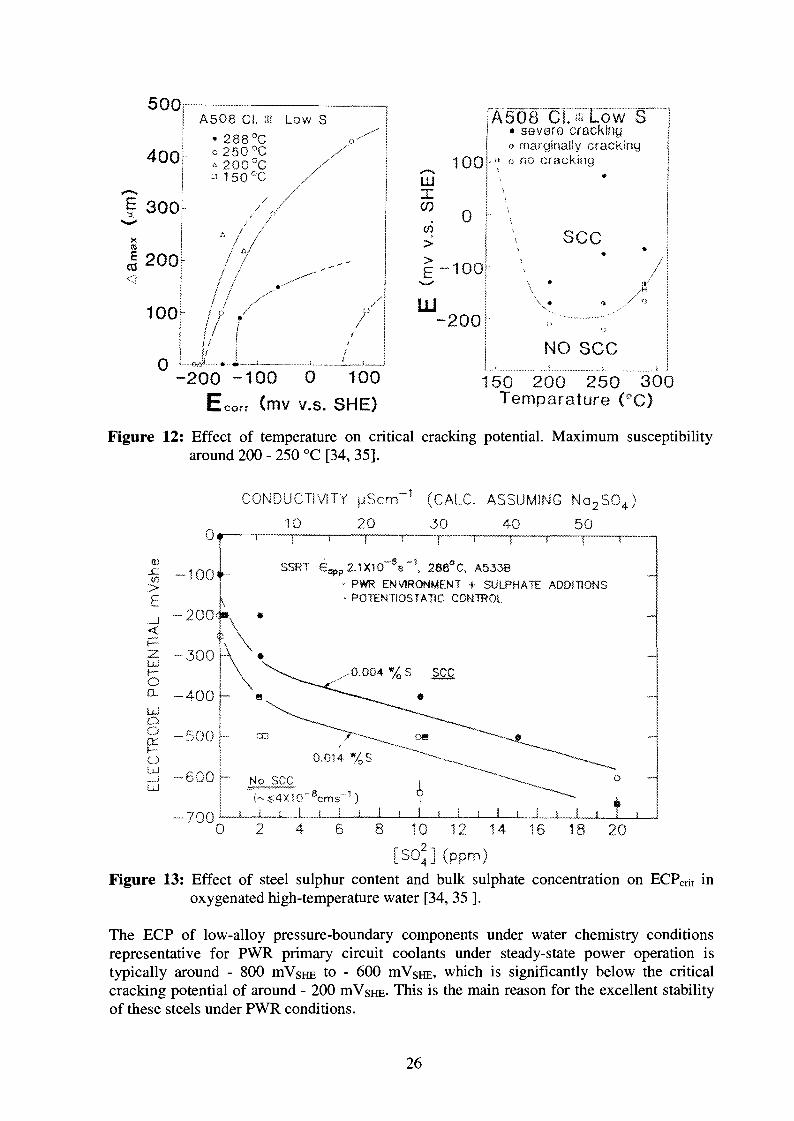
The ECP is more fundamental for SCC/SICC than the content of oxygen respectively contentof all oxidising agents [16, 59]. Depending on flow rate, temperature and material, 5 ppb to100 ppb dissolved oxygen is sufficient to exceed the critical cracking potential of ca.- 200 mVsHE [16, 33 - 35, 97, 98] in high-purity water. The critical potential ECPcrit isdependent on temperature, steel sulphur content, bulk sulphur-anion concentration and strain-rate (see Figure 12 - 15, 17). ECPcrit decreases with increasing sulphur content of the steel[34, 35, 60], and with increasing sulphate content of the environment [34, 35] (see Figure 13).The critical potential has sometimes been related to the passivation potential Ep or thestability boundary of Fe2O3/Fe3C"4 [85], but the role of ECP is probably better understood byits effect on mass transport in the crack enclave and on the enrichment of sulphur-anionspecies in the crack-tip environment and by the dominant effect of sulphur-anion species oncrack growth and repassivation (low/high sulphur behaviour (see Section 4)). The ECP, steelsulphur content and bulk sulphur-anion content are interrelated by crack-tip sulphur-anionactivity. The critical potential can then be related to a critical sulphur-anion concentration inthe crack-tip environment and to the transition between the low/high sulphur crack growthbehaviour. Above ECPcrit, the EAC susceptibility range (temperature/strain-rate/strain) issignificantly extended [11] with increasing ECP. In relative pure high-temperature water, thecrack growth rates may increase with increasing ECP and then probably saturates, when thehigh sulphur behaviour is achieved [86 - 88]. In LCF tests, when all threshold conditions aresatisfied, fatigue life decreases logarithmically above a DO of 50 ppb and the effect seems tosaturate at 500 ppb DO [102, 103]. Fatigue life is insensitive to DO levels below 50 ppb orwhen any other threshold conditions is not satisfied.
25
500r
4001
? 300
J2OO^
A508 CI. «i Low S• 288°Co250°C
7/
II/ /
mXCO
CO
AUU
1
-1
00
0
00
JA508 C I . IHLOW S1 • severe cracking
« marginally cracking-" o no cracking
\
sec\.
y j-200
0Ij ;
•••>&/$ m 3
NO SCC
-200 ~100 0 100(mv v.s. SHE)
150 200 250 300Temparature (°C)
Figure 12: Effect of temperature on critical cracking potential. Maximum susceptibilityaround 200 - 250 °C [34, 35].
CONDUCTIVITY pScm"1 (CALC. ASSUMING N Q 2 S 0 4 )
20 30 40 50
SSRT € « , p 2.1X10 s , 288 C, A533B
PWR ENVIRONMENT + SULPHATE ADDITIONSPOTENTiOSTATIC CONTROL
^0.004 %S SCC
I I I L__i JL_L_J
d - 6 0 0 j - No seeUJ
-70010 12 14 16 18 20
[SO?] (ppm)Figure 13: Effect of steel sulphur content and bulk sulphate concentration on ECPcrit in
oxygenated high-temperature water [34, 35 ].
The ECP of low-alloy pressure-boundary components under water chemistry conditionsrepresentative for PWR primary circuit coolants under steady-state power operation istypically around - 800 mVsHE to - 600 mVSHE, which is significantly below the criticalcracking potential of around - 200 mVsHE- This is the main reason for the excellent stabilityof these steels under PWR conditions.
26
100
SSST, 1*10"6s-"hpw, 288 aClow-flew cutcclcve
msee
200 _
S. -300
o o
- 4 0 0 -
NO SCG
OA533-B A508 A533-B
i < ;
A533-BJ 1
0,005 0,010 0,015 0,020 0,025
b content
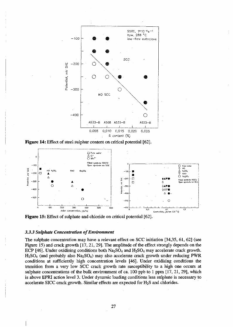
Figure 14: Effect of steel sulphur content on critical potential [62].
- i o o >••
I
Q Pure wa r̂A Ci-Q SO/"
f i l led symbols TGSCC0p«n syrnbcis no SCC
I
I I:> -zoo H3
HCI
A
A
o A
- D
•s0- - 4
-500 i-O
200 300 400
Anion concentrotion, j;g/kfj
• A T *0
A • •
. O
Conductivity, uS/cm (25
n0\?
Pure wat«HCi
KoCI
Fi-ifid 3ymJ>o:B TCSiiC
: f
*C)
: : : , :
Figure 15: Effect of sulphate and chloride on critical potential [62].
3.3.3 Sulphate Concentration of Environment
The sulphate concentration may have a relevant effect on SCC initiation [34,35, 61, 62] (seeFigure 15) and crack growth [17, 21, 29]. The amplitude of the effect strongly depends on theECP [46]. Under oxidising conditions both Na2SC>4 and H2SO4 may accelerate crack growth.H2SO4 (and probably also Na2SC>4) may also accelerate crack growth under reducing PWRconditions at sufficiently high concentration levels [46]. Under oxidising conditions thetransition from a very low SCC crack growth rate susceptibility to a high one occurs atsulphate concentrations of the bulk environment of ca. 100 ppb to 1 ppm [17, 21, 29], whichis above EPRI action level 3. Under dynamic loading conditions less sulphate is necessary toaccelerate SICC crack growth. Similar effects are expected for H2S and chlorides.
27
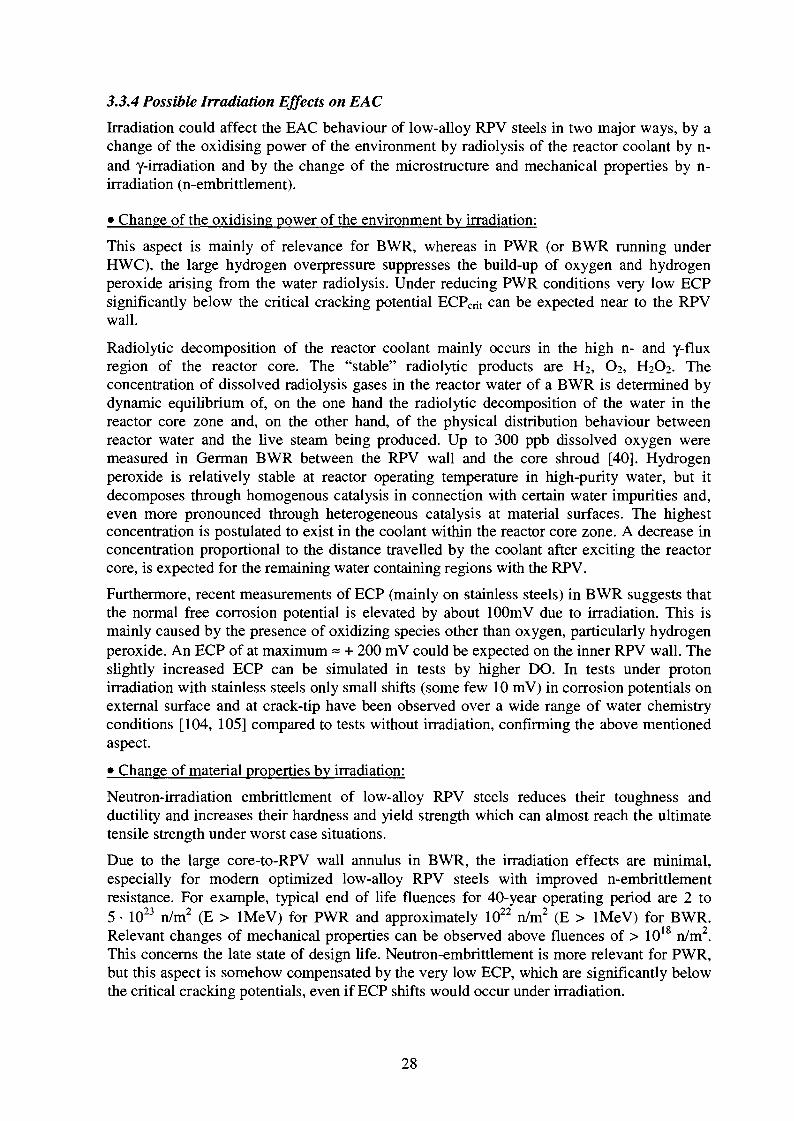
3.3.4 Possible Irradiation Effects on EAC
Irradiation could affect the EAC behaviour of low-alloy RPV steels in two major ways, by achange of the oxidising power of the environment by radiolysis of the reactor coolant by n-and y-irradiation and by the change of the microstructure and mechanical properties by n-irradiation (n-embrittlement).
• Change of the oxidising power of the environment by irradiation:
This aspect is mainly of relevance for BWR, whereas in PWR (or BWR running underHWC), the large hydrogen overpressure suppresses the build-up of oxygen and hydrogenperoxide arising from the water radiolysis. Under reducing PWR conditions very low ECPsignificantly below the critical cracking potential ECPcrit can be expected near to the RPVwall.
Radiolytic decomposition of the reactor coolant mainly occurs in the high n- and y-fluxregion of the reactor core. The "stable" radiolytic products are H2, O2, H2O2. Theconcentration of dissolved radiolysis gases in the reactor water of a BWR is determined bydynamic equilibrium of, on the one hand the radiolytic decomposition of the water in thereactor core zone and, on the other hand, of the physical distribution behaviour betweenreactor water and the live steam being produced. Up to 300 ppb dissolved oxygen weremeasured in German BWR between the RPV wall and the core shroud [40]. Hydrogenperoxide is relatively stable at reactor operating temperature in high-purity water, but itdecomposes through homogenous catalysis in connection with certain water impurities and,even more pronounced through heterogeneous catalysis at material surfaces. The highestconcentration is postulated to exist in the coolant within the reactor core zone. A decrease inconcentration proportional to the distance travelled by the coolant after exciting the reactorcore, is expected for the remaining water containing regions with the RPV.
Furthermore, recent measurements of ECP (mainly on stainless steels) in BWR suggests thatthe normal free corrosion potential is elevated by about lOOmV due to irradiation. This ismainly caused by the presence of oxidizing species other than oxygen, particularly hydrogenperoxide. An ECP of at maximum = + 200 mV could be expected on the inner RPV wall. Theslightly increased ECP can be simulated in tests by higher DO. In tests under protonirradiation with stainless steels only small shifts (some few 10 mV) in corrosion potentials onexternal surface and at crack-tip have been observed over a wide range of water chemistryconditions [104, 105] compared to tests without irradiation, confirming the above mentionedaspect.
• Change of material properties by irradiation:
Neutron-irradiation embrittlement of low-alloy RPV steels reduces their toughness andductility and increases their hardness and yield strength which can almost reach the ultimatetensile strength under worst case situations.
Due to the large core-to-RPV wall annulus in BWR, the irradiation effects are minimal,especially for modern optimized low-alloy RPV steels with improved n-embrittlementresistance. For example, typical end of life fluences for 40-year operating period are 2 to5 • 1023 n/m2 (E > lMeV) for PWR and approximately 1022 n/m2 (E > lMeV) for BWR.Relevant changes of mechanical properties can be observed above fluences of > 1018 n/m2.This concerns the late state of design life. Neutron-embrittlement is more relevant for PWR,but this aspect is somehow compensated by the very low ECP, which are significantly belowthe critical cracking potentials, even if ECP shifts would occur under irradiation.
28
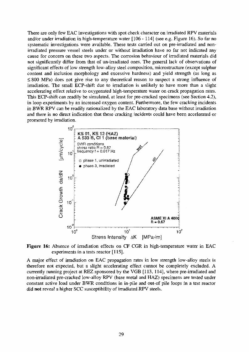
There are only few EAC investigations with spot check character on irradiated RPV materialsand/or under irradiation in high-temperature water [106 - 114] (see e.g. Figure 16). So far nosystematic investigations were available. These tests carried out on pre-irradiated and non-irradiated pressure vessel steels under or without irradiation have so far not indicated anycause for concern on these two aspects. The corrosion behaviour of irradiated materials didnot significantly differ from that of un-irradiated ones. The general lack of observations ofsignificant effects of low strength low-alloy steel composition, microstructure (except sulphurcontent and inclusion morphology and excessive hardness) and yield strength (as long as< 800 MPa) does not give rise to any theoretical reason to suspect a strong influence ofirradiation. The small ECP-shift due to irradiation is unlikely to have more than a slightaccelerating effect relative to oxygenated high-temperature water on crack propagation rates.This ECP-shift can readily be simulated, at least for pre-cracked specimens (see Section 4.2),in loop experiments by an increased oxygen content. Furthermore, the few cracking incidentsin BWR RPV can be readily rationalized by the EAC laboratory data base without irradiationand there is no direct indication that these cracking incidents could have been accelerated orpromoted by irradiation.
10s
e 10
KS01, KS12fHAZ)A 533 B, Cl 1 (base material)BWR conditionsstress ratio R = 0.8?frequency f = 0.017 Hz
o phase 1, unirradiated• phase 3, irradiated
O ASME XIA 400CR » 0.67
Stress intensity AK [MPaVm]1Cf
Figure 16: Absence of irradiation effects on CF CGR in high-temperature water in EACexperiments in a tests reactor [115].
A major effect of irradiation on EAC propagation rates in low strength low-alloy steels istherefore not expected, but a slight accelerating effect cannot be completely excluded. Acurrently running project at REZ sponsored by the VGB [113, 114], where pre-irradiated andnon-irradiated pre-cracked low-alloy RPV (base metal and HAZ) specimens are tested underconstant active load under BWR conditions in in-pile and out-of pile loops in a test reactordid not reveal a higher SCC susceptibility of irradiated RPV steels.
29
3.4 Mechanical/Loading Parameters
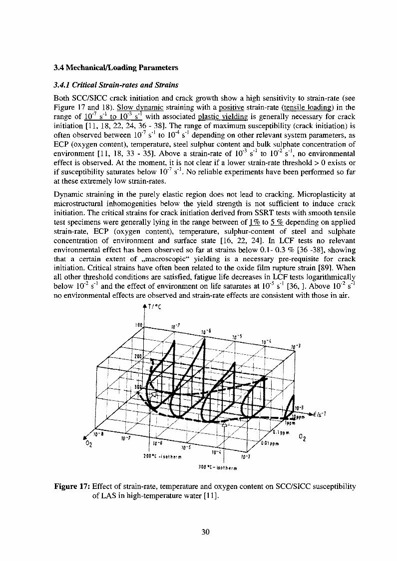
3.4.1 Critical Strain-rates and Strains
Both SCC/SICC crack initiation and crack growth show a high sensitivity to strain-rate (seeFigure 17 and 18). Slow dynamic straining with a positive strain-rate (tensile loading) in therange of 10'7 s"1 to 10"3 s"1 with associated plastic yielding is generally necessary for crackinitiation [11, 18, 22, 24, 36 - 38]. The range of maximum susceptibility (crack initiation) isoften observed between 10"7 s"1 to 10"4 s"1 depending on other relevant system parameters, asECP (oxygen content), temperature, steel sulphur content and bulk sulphate concentration ofenvironment [11, 18, 33 - 35]. Above a strain-rate of 10"3 s"1 to 10"2 s"1, no environmentaleffect is observed. At the moment, it is not clear if a lower strain-rate threshold > 0 exists orif susceptibility saturates below 10"7 s"1. No reliable experiments have been performed so farat these extremely low strain-rates.
Dynamic straining in the purely elastic region does not lead to cracking. Microplasticity atmicrostructural inhomogenities below the yield strength is not sufficient to induce crackinitiation. The critical strains for crack initiation derived from SSRT tests with smooth tensiletest specimens were generally lying in the range between of J_% to 5 % depending on appliedstrain-rate, ECP (oxygen content), temperature, sulphur-content of steel and sulphateconcentration of environment and surface state [16, 22, 24]. In LCF tests no relevantenvironmental effect has been observed so far at strains below 0.1- 0.3 % [36 -38], showingthat a certain extent of ,,macroscopic" yielding is a necessary pre-requisite for crackinitiation. Critical strains have often been related to the oxide film rupture strain [89]. Whenall other threshold conditions are satisfied, fatigue life decreases in LCF tests logarithmicallybelow 10"2 s"1 and the effect of environment on life saturates at 10"5 s"1 [36, ]. Above 10"2 s"1
no environmental effects are observed and strain-rate effects are consistent with those in air.
"3
02
280*C -isotherm
390 "C-ijotIttrm
Figure 17: Effect of strain-rate, temperature and oxygen content on SCC/SICC susceptibilityof LAS in high-temperature water [11].
30

In static test with smooth tensile test specimens, crack initiation was only observed at stresslevels above the high-temperature yield strength [31, 38], if specimens where exposed to theenvironment before cessation of the low-temperature creep [38]. No SCC was observed withpre-cracked specimens, which have been loaded in an inert environment and where completeexhaustion of low temperature creep has been allowed to occur prior to the exposure of thespecimens to the test environment [29]. These observations are demonstrating again theimportance of slow dynamic straining for crack initiation.
The primary design stresses are limited to values below the yield strength Rp (Rp/S, S: safetyfactor). Therefore, in general plastic yielding in service is only observed at pre-existingdefects, in regions of increased (local) stress, and/or for high secondary (thermal) stresses orresidual stresses. Dynamic straining primarily arises from dynamic/cyclic external loading(transient LWR operation conditions: thermal and pressurisation cycles during start-up/shut-down, stand-by, thermal fluctuation, stripping or thermal stratification), low temperaturecreep in highly stressed regions (notches, welding defects, ...) or by the crack growth (puremechanical (fatigue) or corrosion-assisted) itself.
1/2.,dK/dt [MPam'Vh]
1x10° 1x101 1x10²
1X10"6
^ 1x10"7
1x10
1x10⁻¹⁰
O SA 533 B Cl. 1 (0.018 wt.% S)• SA 508 Cl. 2 (0.004 wt. % S)A 20 MnMoNi 5 5 (0.004 wt.% S)
Linear Fit of O /95 % Prediction Interval
<Aas|CC>/At.E a (dCOD^/dt)0
<Aaslcc>/At'E a (dK/dt)08
1x10'7 1X10"6 1x10"5 1x10" 1x10^
dCODLL/dt [mm/s]
Figure 18: Effect of loading rate ("strain-rate") on SICC crack growth rates [29].
Corrosion-assisted crack growth rate is strongly related to strain-rate. For givenenvironmental and material conditions, the crack growth rate is increasing with increasingstrain-rate following roughly a power law (see also Figure 18 and Section 4.1.1). At very highstrain-rates no corrosion-assisted crack growth is observed up to the onset of pure mechanicalductile crack growth. Again it is not fully clear at present time, if a lower strain-rate thresholdlimit for corrosion-assisted crack growth > 0 exists or not. The strain-rate effect may berationalised by rupture/reformation cycles of the protective oxide film by both anodicdissolution or hydrogen-assisted SCC mechanisms. Dynamic strain ageing may be analternative explanation or additional contributing factor for the strain-rate dependence ofSCC/SICC crack growth.
31
3.4.2 Stress Intensity Factor Threshold for SCC KISCc
The stress intensity factor threshold Kiscc for SCC depends on strain-rate (initial loadingprocedure) and on other system parameters such as ECP, temperature, sulphur-content ofsteel, sulphate concentration of environment, etc. For nominal static loading conditionsapparent Kiscc-values from 20 MPa-m1/2 to 60 MPa-m1/2 [15, 21, 28, 29, 45] have beenreported in oxygenated high-temperature water (simulated BWR conditions). Lowerthresholds were observed in surface-cracked specimens with significant plastic yieldingmaking Ki-calculations invalid [63]. In slow rising displacement/load respectively J-R-tests atdifferent displacement rates, the lowest Kiscc-values where cracking has been observed underslow rising loading were ranging from 23 MPa-m1/2 to 40 MPa-m1/2 [29, 45, 64 - 67]depending on the steel sulphur content and the environmental conditions. The Kiscc-valuedecreases with decreasing load/strain-rate [29]. It is not yet clear if KIScc saturates orincreases again at very low strain-rates [29]. At very high loading rates crack initiation occursat Ku without any remarkable environmental effect [64 -67].
In oxygenated high-temperature water of high and moderate purity SCC crack initiation withminor cracking and subsequent crack arrest has been observed above 20 to 30 MPam1/2,whereas sustained (with respect to operational time scales) SCC crack growth has only beobserved above 40 MPa-m1/2 to 60 MPa-m1/2 [17, 28, 29, 90]. In oxygenated high-temperaturewater with high impurity levels (SO42" + Cl" > 500 ppb) under low-flow or quasi-stagnantconditions, sustained cracking has been observed down to stress intensity factors of 20 -30MPam1/2 [15, 21, 45]. Under reducing PWR conditions no SCC crack growth wasobserved up to very high Kj-values near to 100 MPa-m1/2 or to Ku [16, 68].
3.5 Material Parameters
3.5.1 Steel Sulphur-Content, MnS-Inclusions
The sulphur content of the steel, the size, type (chemical composition), morphology andspatial distribution of MnS-inclusions are the material parameters having the strongest effecton SCC/SICC susceptibility [14, 16, 22-24, 34-35, 84, 86, 91-96]. It has been shown thatEAC initiation [36 -38, 97, 98], EAC growth [ 12 -14, 16, 34, 35, 97, 98] and the pittingbehaviour [116 - 118] of LAS are affected by the presence of MnS-inclusions.
Although the majority of the embedded inclusions appear to be mainly MnS, few of them arestoichometric MnS, and some inclusions are FeS or mixed (Mn,Fe)S. The variations insulphide compositions may be related to the steel-making process [119], and differentsulphide compositions may produce different levels of electrochemical attack [120 - 122].MnS is readily soluble in acidic water, FeS and NiS are somewhat less soluble, and CrS is,,sparingly" soluble [123]. The dissolution of embedded sulphides intersected by the growingcrack results in sulphide-anions (S2\ HS") in the crack-tip environment.
The local sulphur content and morphology of MnS-inclusions depend on the steel making (—>segregation) and fabrication process of the plate (forming: hot rolling, forging,...), and theycan significantly differ in large plates [124]. Sulphur strongly accumulates in the liquid phaseduring the solidification process. MnS is a relatively low melting compound, and hencemigrates in the molten state toward the centre of a solidifying ingot. The concentration ofsulphides is generally higher in the centre of the plate. In segregation zones local sulphurcontent can be several times larger than the mean bulk sulphur content [125]. Sulphides tendto be rod-like in unidirectionally-rolled plates, and disk-like in cross-rolled plates, while inforgings the sulphides tend to be more spherical. Modern RPV steels have both a smaller
32

sulphur content and a more homogeneous sulphur distribution than older ones. Theorientation (TL, LT, TS, ...) and location of the specimens may therefore be further importantfactors and may be an important source of scatter of experimental SCC/SICC data.
It has been reported, that the T-L orientation produces higher CF CGR than the LTorientation which, in turn, produces higher CF CGR than the LS orientation [126], while inan other reference, the rates for the LS, LT and TL orientation were found to be essentiallysimilar [127]. The size and morphology of the MnS-inclusions seem to be as important as thesulphur content itself [16]. Plate-like or rod-shaped sulphides are often reported to be moredetrimental than spherical inclusions. This all suggests that steel making process and productform (plate vs. forging vs. weld) may play a role in EAC susceptibility. The low apparentEAC susceptibility of welds is attributed to the very small, uniformly-distributed sulphides,as well as to the compositional differences between wrought steels and welds [16].
As mentioned above, the bulk sulphur content as generally provided on materialcertifications, is not an optimum indicator of the EAC susceptibility of a given steel. Otherattributes (shape, size, ...) may be as least as important as the sulphur content. A promisingparameter is the area fraction of MnS-inclusions, which correlated well with the EACsusceptibility of the materials in some investigations [128].
The effects of steel sulphur content are svnergistic with environmental variables, such as(sulphur-) anionic impurities in the bulk environment, ECP (dissolved oxygen content) andflow rate. This is believed to be due to the creation of a sulphur-rich crack-tip environmentresponsible for EAC, which arises from the dissolution of MnS intersected by the crack andby the transport of sulphur-anions by migration/diffusion/convection in the crack enclave.The sulphur-anions can either be present from the dissolution sulphides intersected by thegrowing crack or they can be present in the water as an impurity. A high steel sulphur contentis therefore not a pre-requisite for the occurrence of EAC. The controlling factor is thesulphur-anion concentration at the crack-tip. Further important factors controlling the crack-tip sulphur-anion concentration are the crack growth rate itself (which governs theintersection rate of new, fresh, dissolvable MnS-inclusions) and the dissolution rate of theMnS-inclsuions, which is not well known. The dissolution rate is dependent on temperature,potential and pH, type of sulphide-inclusions and eventually also on their size and shape[84].The effect of MnS-inclusions on EAC and the interrelation between ECP/MnS/bulksulphur-anion content are discussed in detail in Section 4.1 and 4.2. It has been proposed thata critical sulphur-anion concentration in the crack-tip environment has to be achieved forEAC [84]. A high ECP and/or high sulphur-anion concentration in the bulk environment andlow flow rate favour the formation of a sulphur rich crack-tip environment and susceptibilityof low sulphur steels can be as high as in high sulphur steels under these conditions.
In smooth specimens SCC/SICC initiation and pitting often occurs at MnS-inclusions whichintersect the steel surface [33, 44, 60, 96]. In high sulphur steels generally more MnS-inclusions intersect the steel surface, which increases the probability for crack initiation.Kunyia [31] showed that whilst SICC rates where the same for low and medium sulphursteels, the number of initiation sites was greater in the latter case. Hurst et al. [129] showedthat if specimen orientation was such as to maximise access of the environment to the crevicecreated by decohesion of an outcropping sulphide inclusion, localized SICC could beobserved in a stagnant autoclave in nominally deoxygenated conditions. If the MnS-inclusions intersecting the steel surface were removed before starting an SSRT test, no SICCin high-purity water is observed [93]. Under highly oxidizing conditions at low orintermediate temperatures and low flow rate conditions, where pitting and the formation of anaggressive occluded water chemistry is strongly favoured [93, 94], initiation occurs often at
33
pits and the effect of MnS is less dominant. In pre-cracked specimens, large area ofdissolvable MnS-inclusions intersected by the crack plane are available and the restrictedmass transport in the crack enclave favours the formation of a high sulphur-anion crack-tipenvironment. The effect of MnS is less distinct for crack growth than for crack initiation.MnS-inclusions which intersect the pre-crack front are found to be less dominant for thelocation of crack initiation in pre-cracked specimen than in smooth specimens [29].
SICC/SCC susceptibility is generally decreasing with decreasing steel sulphur content and,higher SICC/SCC CGR are sometimes observed in steels with higher sulphur content. Theeffect of steel sulphur content is less pronounced for crack growth than for crack initiation, inparticular under oxidizing BWR conditions. The critical cracking potential is decreasing withincreasing steel sulphur content [34, 35, 60, 62]. In many cases, a high steel sulphur contentis significantly extending the range of EAC conditions (ECP, DO, bulk sulphur-anioncontent, strain-rates, ...) and shifting the thresholds to less severe conditions [16]. Forexample, lower ECP, smaller bulk sulphur-anion contents and lower strain-rates arenecessary to induce EAC in high sulphur materials than in low sulphur ones [16]. If there is arelevant effect of steel sulphur content on SCC/SICC or not, depends on the values andcombination of the following interrelated and synergistic system parameters as the ECP, bulksulphur-anion concentration, flow rate, temperature, strain-rate and crack growth rate. Thesynergism with other system parameters is one further reason for some apparent disparityconcerning the effect of MnS on EAC.
In LCF tests, the effect of sulphur content on fatigue life depends on the DO content of thewater. When the threshold conditions are satisfied and for DO content of 1.0 ppm, the fatiguelife decreases with increasing sulphur content [100]. Limited data suggest that environmentaleffects on fatigue life saturate at a sulphur content of 0.015 wt.%. At high DO levels, e.g.> 1.0 ppm, the fatigue life seems to be insensitive to sulphur content in the range of 0.002 -0.015 wt.% [100]. When any one of the threshold conditions are not satisfied, environmentaleffects are minimal and relatively insensitive to changes in sulphur content.
Steels with a sulphur-content of less than 0.003 wt.% show a very low susceptibility to EACcrack growth over a wide range of environmental and loading conditions and are oftenregarded as ,,immune", but SICC has even been observed in SSRT tests in extremely lowsulphur (0.001 wt. % S) forging material in oxygenated high-temperature water at DO > 100ppb in the temperature range form 150 °C to 250 °C [97, 98]. Furthermore, the low sulphurcontent results in a higher toughness, larger critical crack sizes and higher safety margins. Butthe beneficial effect of a low steel sulphur content concerning EAC disappears under stronglyoxidising (high ECP) and/or at high bulk impurity levels (high bulk sulphur-anionconcentration) or under suitable strain-rate/temperature conditions [29, 216]. Sustained SCCunder static loading may be even observed in deoxygenated high-temperature water at verylow ECP, if H2SO4 is added to the bulk water in high concentrations [46, 86].
3.5.2 Yield Strength Rp, Microstructure
Although, the effect of microstructure on SCC/SICC susceptibility has not yet beensystematically studied in low-alloy steels in high-temperature water, the following trendsappear:
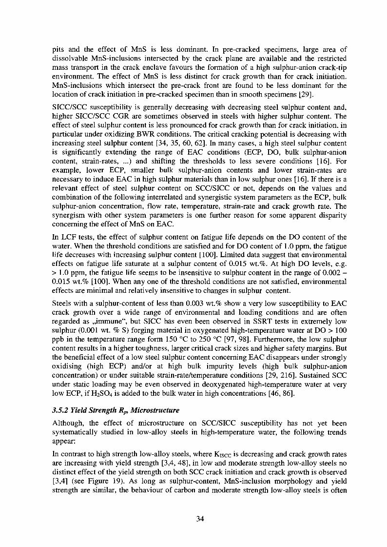
In contrast to high strength low-alloy steels, where Kiscc is decreasing and crack growth ratesare increasing with yield strength [3,4, 48], in low and moderate strength low-alloy steels nodistinct effect of the yield strength on both SCC crack initiation and crack growth is observed[3,4] (see Figure 19). As long as sulphur-content, MnS-inclusion morphology and yieldstrength are similar, the behaviour of carbon and moderate strength low-alloy steels is often
34
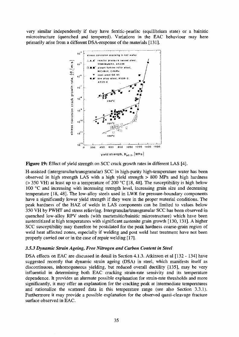
very similar independently if they have ferritic-pearlitc (equilibrium state) or a bainiticmicrostructure (quenched and tempered). Variations in the EAC behaviour may hereprimarily arise from a different DSA-response of the materials [131].
r " in het w»t«t
..A.JC' r«3clo< pr«ssuf« vess«! ',!OMnMo«)S5. ASMS
LS.K* steam iutbimt rotor ste*NiCrMoV, CrNtMo
• easi • *««! OS 40• , • " l»w atioy »t*cl, ,
A333-6
o
u
oo
__!„ I J
a 200 400 soo 800 ioao isoo i<«oo ISOO
yield slrength, Rp0,zi | ^ p a ]
Figure 19: Effect of yield strength on SCC crack growth rates in different LAS [4].
H-assisted (intergranular/transgranular) SCC in high-purity high-temperature water has beenobserved in high strength LAS with a high yield strength > 800 MPa and high hardness(> 350 VH) at least up to a temperature of 200 °C [18, 48]. The susceptibility is high below100 °C and increasing with increasing strength level, increasing grain size and decreasingtemperature [18, 48]. The low-alloy steels used in LWR for pressure-boundary componentshave a significantly lower yield strength if they were in the proper material conditions. Thepeak hardness of the HAZ of welds in LAS components can be limited to values below350 VH by PWHT and stress relieving. Intergranular/transgranular SCC has been observed inquenched low-alloy RPV steels (with martensitic/bainitic microstructure) which have beenaustentitized at high temperatures with significant austenite grain growth [130, 131]. A higherSCC susceptibility may therefore be postulated for the peak hardness coarse-grain region ofweld heat affected zones, especially if welding and post weld heat treatment have not beenproperly carried out or in the case of repair welding [17].
3.5.3 Dynamic Strain Ageing, Free Nitrogen and Carbon Content in Steel
DSA effects on EAC are discussed in detail in Section 4.1.3. Atkinson et al [132 - 134] havesuggested recently that dynamic strain ageing (DSA) in steel, which manifests itself asdiscontinuous, inhomogeneous yielding, but reduced overall ductility [135], may be veryinfluential in determining both EAC cracking strain-rate sensivity and its temperaturedependence. It provides an alternate possible explanation for strain-rate thresholds and moresignificantly, it may offer an explanation for the cracking peak at intermediate temperaturesand rationalize the scattered data in this temperature range (see also Section 3.3.1).Furthermore it may provide a possible explanation for the observed quasi-cleavage fracturesurface observed in EAC.
35
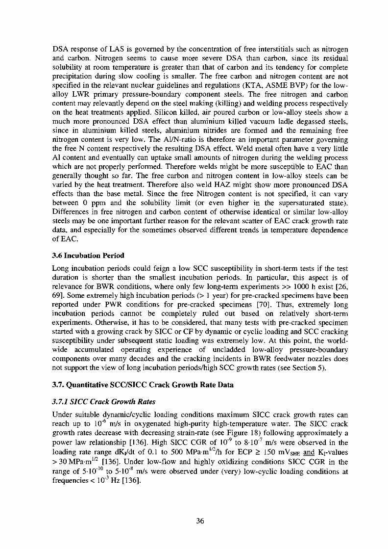
DSA response of LAS is governed by the concentration of free interstitials such as nitrogenand carbon. Nitrogen seems to cause more severe DSA than carbon, since its residualsolubility at room temperature is greater than that of carbon and its tendency for completeprecipitation during slow cooling is smaller. The free carbon and nitrogen content are notspecified in the relevant nuclear guidelines and regulations (KTA, ASME BVP) for the low-alloy LWR primary pressure-boundary component steels. The free nitrogen and carboncontent may relevantly depend on the steel making (killing) and welding process respectivelyon the heat treatments applied. Silicon killed, air poured carbon or low-alloy steels show amuch more pronounced DSA effect than aluminium killed vacuum ladle degassed steels,since in aluminium killed steels, aluminium nitrides are formed and the remaining freenitrogen content is very low. The Al/N-ratio is therefore an important parameter governingthe free N content respectively the resulting DSA effect. Weld metal often have a very littleAl content and eventually can uptake small amounts of nitrogen during the welding processwhich are not properly performed. Therefore welds might be more susceptible to EAC thangenerally thought so far. The free carbon and nitrogen content in low-alloy steels can bevaried by the heat treatment. Therefore also weld HAZ might show more pronounced DSAeffects than the base metal. Since the free Nitrogen content is not specified, it can varybetween 0 ppm and the solubility limit (or even higher in the supersaturated state).Differences in free nitrogen and carbon content of otherwise identical or similar low-alloysteels may be one important further reason for the relevant scatter of EAC crack growth ratedata, and especially for the sometimes observed different trends in temperature dependenceof EAC.
3.6 Incubation Period
Long incubation periods could feign a low SCC susceptibility in short-term tests if the testduration is shorter than the smallest incubation periods. In particular, this aspect is ofrelevance for BWR conditions, where only few long-term experiments » 1000 h exist [26,69]. Some extremely high incubation periods (> 1 year) for pre-cracked specimens have beenreported under PWR conditions for pre-cracked specimens [70]. Thus, extremely longincubation periods cannot be completely ruled out based on relatively short-termexperiments. Otherwise, it has to be considered, that many tests with pre-cracked specimenstarted with a growing crack by SICC or CF by dynamic or cyclic loading and SCC crackingsusceptibility under subsequent static loading was extremely low. At this point, the world-wide accumulated operating experience of uncladded low-alloy pressure-boundarycomponents over many decades and the cracking incidents in BWR feedwater nozzles doesnot support the view of long incubation periods/high SCC growth rates (see Section 5).
3.7. Quantitative SCC/SICC Crack Growth Rate Data
3.7.1 SICC Crack Growth Rates
Under suitable dynamic/cyclic loading conditions maximum SICC crack growth rates canreach up to 10"6 m/s in oxygenated high-purity high-temperature water. The SICC crackgrowth rates decrease with decreasing strain-rate (see Figure 18) following approximately apower law relationship [136]. High SICC CGR of 10"9 to 8-10"7 m/s were observed in theloading rate range dKr/dt of 0.1 to 500 MPam1/2/h for ECP > 150 mVSHE and Krvalues> 30MPam1/2 [136]. Under low-flow and highly oxidizing conditions SICC CGR in therange of 5-10" to 5-10" m/s were observed under (very) low-cyclic loading conditions atfrequencies < 10"3 Hz [136].
36

3.7.2 SCC Crack Growth Rates andKIScc
In oxygenated high-temperature water, SCC plateau crack growth rates of 10"8 m/s up to10~7m/s have been observed under pure static loading under highly faulted water chemistryconditions (high concentrations of specific anionic impurities > EPRI action level 3) and/orfor highly stressed specimens either loaded near to KD or with a high degree of plasticity inthe remaining ligament [15, 21, 29, 45]. For nominal static loading conditions Kiscc-valuesfrom 20 MPam1/2 to 60 MPa-m1/2 [15, 21, 28, 29, 45] have been reported for simulated BWRconditions. In oxygenated high-temperature water of high and moderate purity SCC crackinitiation with minor cracking and subsequent crack arrest has been observed above 20 to30 MPa-mI/2, whereas sustained (with respect to operational time scales) SCC crack growthhas only be observed above 40 to 60 MPam1/2 [17, 28, 29, 90]. In oxygenated high-temperature water with high impurity levels (SO4 " + Cl" > 500 ppb) under low-flow or quasi-stagnant conditions, sustained cracking has been observed down to stress intensity factors of20 - 30 MPa-m1/2 [15, 21, 45]. Under reducing PWR conditions no SCC crack growth wasobserved up to very high Ki-values near to 100 MPa-m1/2 or to Ku [16, 68].
Figure 20 shows a compilation of experimental results on corrosion-assisted crack growthrates under static loading conditions in low-alloy pressure-boundary component steels inoxygenated high-temperature water at 288 °C/240 °C [4, 12, 15, 18 -26]. Additionally, anupper bounding line according to Speidel [15] and an envelope of newer results of MPAStuttgart [23] are shown. Also included in Figure 20 are the ,,low sulphur" and ,,high sulphurline" due to the work of Ford et al. [4] taking both into account mechanistical considerationsbased on the film rupture/anodic dissolution mechanism and the SCC data base, as shown inthe diagram. The tremendous scatter of 3 to 5 orders of magnitude under nominally identical,or at least similar testing conditions makes rational life prediction impossible and hastherefore led to divergent assessments on the possible effect of SCC on the RPV structuralintegrity.
Many tests revealing the high crack growth rates plotted in Figure 20 have been performedunder a combination of both gross yielding of the remaining specimen ligament, which is notrelevant to the thick-walled RPV structure, and aggressive water-chemistry conditions, whichare not representative of current BWR operation practice [17]. Attempts have been made toreduce this tremendous scatter by data reduction methods, taking into account the differentquality and performance of the experiments [41]. It was shown that, in older investigations,system parameters having a strong influence on crack growth were neither sufficientlycontrolled and monitored, nor documented. Thus, the transferability and relevance of thesedata to pressure-boundary components and to BWR power operation conditions cannot besatisfactorily evaluated. Consequentially, assessment of the different data quality [41] clearlyrevealed a need for further experimental parameter studies, since only a few, well-characterised and reproducible experiments, which fulfil current quality requirements ontesting [137, 210], have been reported in the literature.
37
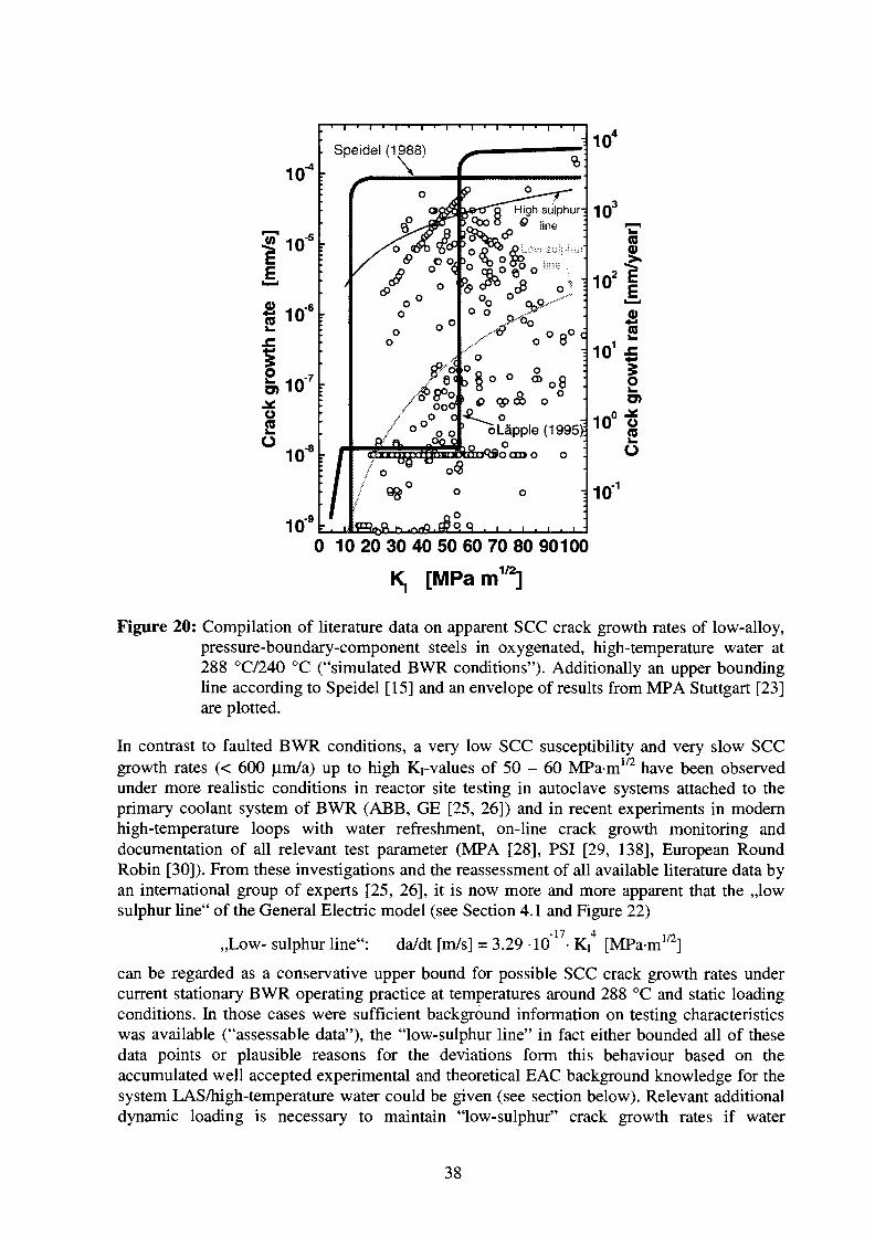
110!
10,-6
2en§ 1 0 '
8°
Speidei(1988)
op oo o
oLapple(1995);oOCXDO O
0 10 20 30 40 50 60 70 80 90100
K, [MPam1/2]
Figure 20: Compilation of literature data on apparent SCC crack growth rates of low-alloy,pressure-boundary-component steels in oxygenated, high-temperature water at288 °C/240 °C ("simulated BWR conditions"). Additionally an upper boundingline according to Speidel [15] and an envelope of results from MPA Stuttgart [23]are plotted.
In contrast to faulted BWR conditions, a very low SCC susceptibility and very slow SCCgrowth rates (< 600 |0,m/a) up to high Ki-values of 50 - 60 MPam1/2 have been observedunder more realistic conditions in reactor site testing in autoclave systems attached to theprimary coolant system of BWR (ABB, GE [25, 26]) and in recent experiments in modernhigh-temperature loops with water refreshment, on-line crack growth monitoring anddocumentation of all relevant test parameter (MPA [28], PSI [29, 138], European RoundRobin [30]). From these investigations and the reassessment of all available literature data byan international group of experts [25, 26], it is now more and more apparent that the ,,lowsulphur line" of the General Electric model (see Section 4.1 and Figure 22)
17 l /2 n,,Low-sulphur line": da/dt [m/s] = 3.29 10 • Ki [MPam1/z]
can be regarded as a conservative upper bound for possible SCC crack growth rates undercurrent stationary BWR operating practice at temperatures around 288 °C and static loadingconditions. In those cases were sufficient background information on testing characteristicswas available ("assessable data"), the "low-sulphur line" in fact either bounded all of thesedata points or plausible reasons for the deviations form this behaviour based on theaccumulated well accepted experimental and theoretical EAC background knowledge for thesystem LAS/high-temperature water could be given (see section below). Relevant additionaldynamic loading is necessary to maintain "low-sulphur" crack growth rates if water
38
chemistry conditions were maintained within current BWR operation practice to some extent.Otherwise crack arrest was observed under purely static loading. Very recent preliminary testresults [131] arise the question concerning the conservatism of the "low-sulphur line" atlower intermediate temperatures (200 - 250°C) in susceptible materials (DSA?) and for smallload fluctuations at very high load-ratios (R > 0.95) near to fatigue thresholds AKth.
3.7.3 Possible Reasons for Data Scatter and High SCC Crack Growth Rates
The typical inherent scatter of SCC CGR under constant, reproducible test conditions istypically within one order of magnitude. Slight differences in the test design and operatingpractice are some of the most important reasons for the large scattering of literature SCC datain Figure 20 [14, 137]. Much of the observed scatter is due to primarily an inadequatedefinition of system and due to a high sensivity of the propagation rate to small uncontrolledor unmonitored changes in some of the system parameters [137]. Other possible reasons forinherent data scatter have been discussed in the preceding parts of this section.
Much of the observed scatter in Figure 20 can be attributed to one or several of the followinginterrelated factors:
1. Strain-rate effects:
External loading, crack growth (corrosion-assisted or fatigue) and low temperature creep maycontribute to maintain a positive, tensile (crack-tip) strain-rate and therefore strongly affectthe SCC growth behaviour (see Section 4.1.1). The strain-rate at the beginning of theexperiment may be > 0 or virtually zero depending on test procedure:
- different initial loading procedure: initial loading rate, initial loading: in test environmentvs. in air [14, 29, 138].
- significantly different test durations: especially in short-term tests crack growth issignificantly overestimated under static loading [28,29, 138]
- start of test with actively growing EAC crack (pre-cracking in autoclave, change from hightoo low SCC CGR conditions)
- SSY vs. gross ligament yielding: Many tests were performed with significantly overloadedspecimens (gross ligament yielding), where small scale yielding conditions evidently do notprevail [29]. Under these conditions a sustained crack-tip strain-rate may be maintained bylow temperature creep. Many tests were performed under conditions where the onset ofpure mechanical ductile crack growth cannot be excluded in air (loaded near to the plasticlimit load of the material or to Ku). In many of these tests, crack growth mechanism(TGSCC vs. ductile) has not been verified by post-test fractography in the SEM.
- pure static loading vs. periodical partial unloading, ripple loading, slow monotonicallyrising load: This aspect can be attributed at least in part to the term SCC which can beunderstood either in a narrow sense (EAC under purely static mechanical loading) or as partof the broader spectrum of EAC (including the transition to SICC and low-cycle corrosionfatigue) [20, 25].
- constant load vs. constant displacement [138].
- different pre-cracking procedure (in air vs. in autoclave).
- too short test period after transition from high too low SCC CGR conditions.
39
2. ECP, flow rate, specific impurities
- relevant difference in ECP in spite of similar DO at inlet, because of different flow rates,designs of autoclaves and inadequate electrical isolation of specimens. In older tests ECP isoften not specified.
- specified DO and conductivity at inlet do not represent the real electrochemical and waterchemistry conditions near the specimen surface (large differences between DO andconductivity in inlet and outlet in some older investigations), especially under quasi-stagnant or very low-flow conditions in large autoclave systems.
- flushing of crack-tip electrolyte under high flow rate conditions (see Section 4.4.5)
- inadequate controlling of environmental parameters (static autoclaves) respectively waterchemistry conditions which were not representative for current BWR operating practice(quasi-stagnant, > 1.0 jlS/cm, > 1 ppm Cl" + SO4
2~).
- different type and concentration of impurities in spite of similar inlet conductivities.
3. Material parameters:
- material state which is not representative for LWR primary pressure-boundary components(as specified in the nuclear regulations) (significantly different strength level, hardness,microstructure or heat treatment).
- steel sulphur content, spatial distribution and morphology of MnS, DSA (N/Al).
4. Crack length measurement aspects:
- inadequate determination of crack advance: generally the combination of suitable on-linecrack growth measurement methods (DCPD, ..) with fractographical analysis by SEM(inclusive removement of the oxide film) is necessary for reliably assessing the SCC crackgrowth behaviour, otherwise relevant error can be produced [29, 138].
^ grain diameter, resolution limit of crack length measurement, cyclic plastic zonesize.
- no clear indications for EAC often in connection with too small test duration.
5. Transition CGR, which are not representative for specified testing conditions:
- (unsteady) transition crack growth behaviour after changes of system parameters, too shorttest duration in multiple parameter tests after change of system parameters.
- memory/hysteresis effects because of water chemistry and DO transients (Section 4.4.4).
- crack retardation/acceleration because of crack closure effects after mechanical transients.
40

4. Mechanistical Aspects of EAC of LAS
The following discussion is focused to the crack growth from incipient, mechanically andmicrostructurally long cracks. The dominant effect of crack-tip strain-rate and crack-tipchemistry and the influence of MnS-inclusions and the content of free nitrogen and carbon inthe steel will be explained in Section 4.1 by the most popular crack growth models. InSection 4.2 it will be briefly shown how local crack-tip chemistry is related to the bulkchemistry outside the crack enclave by the different mass transport mechanism (diffusion,migration, convection) and to the local metallurgy and microchemistry in the steel by thedissolution of the MnS-inclusions.
4.1 Crack Growth Mechanisms
EAC mechanisms have been the topic of many reviews [6, 20, 139 - 144] and have beenrecently discussed with their relevance to LAS in high-temperature water [140, 142 - 144]. Itis in the view of many authors (e.g.[20]), that there is a common mechanism for transgranularEAC of LAS under LWR conditions, in the sense that corrosion fatigue and stress corrosioncracking are fundamentally related phenomena and governed by the same processes. In thefollowing, it will not be differentiated between corrosion fatigue and stress corrosioncracking, if not necessary.
For the case of low-alloy steels in high-temperature water, the following potential crackingmechanism have been mainly discussed in literature:
• Film rupture/anodic dissolution (FRAD) (Section 4.1.1)
• Hydrogen-assisted EAC (HAEAC) (Section 4.1.2)
• Dynamic strain ageing (DSA) (Section 4.1.3)
The controlling factors in EAC of LAS are phenomenologically well known but the directexperimental evidence for a specific microscopic crack extension process is still very weak.The exact crack growth mechanism is therefore still under discussion. None of the proposedmechanism can satisfactorily explain all experimentally observed cracking aspects. Currently,the observed cracking behaviour can be best rationalized by a combination of these threefundamental cracking mechanism. At lower temperatures (< 100 °C) and/or high strengthlevels (Rp > 800 MPa) hydrogen effects are more pronounced. At high temperatures(> 150 °C) and/or lower yield strength levels (Rp < 800 MPa) anodic dissolution seems todominate. Under certain combinations of temperature and strain-rate dynamic strain ageingmay give an additional contribution to the crack growth in susceptible materials with a highconcentration of interstitial nitrogen and carbon.
4.1.1 Film Rupture /Anodic Dissolution Mechanism (FRAD)
The quantitative EAC crack growth models (GE-model [20], CEFM [145-146]) in the systemLAS/high-temperature water are all based on the film rupture/anodic dissolution mechanism:
In high-temperature water, a protective oxide film is formed on low-alloy steels which delaysor suppress further corrosion attack and acts as a diffusion barrier for retarded hydrogenuptake. The brittle oxide film can rupture by plastic straining at the crack-tip. Bare metal isthen exposed to the crack-tip electrolyte. Consequently, accelerated local anodic metaldissolution can take place, which finally leads to corrosion-assisted crack growth. The anodicdissolution is stopped by the reformation of the protective oxide film (repassivation). Thesetwo processes are strongly dependent on the aggressivity of crack-tip water chemistry. The
41

crack-tip chemistry itself is related to the bulk water chemistry outside the crack enclave bymass transport processes and to the dissolution of MnS-inclusions respectively the exposureof fresh MnS-inclusions by crack growth. For a sustained corrosion-assisted crack growthrepeated rupture of the protective oxide and therefore sustained crack-tip straining isnecessary.
The relevant parameters in this model are therefore the crack-tip strain-rate, the oxide filmrupture strain and the dissolution/repassivation behaviour, which strongly depends on thecrack-tip chemistry. The following discussion is primarily based on the GE-model [20]:
Film rupture occurs, if the crack-tip strain reaches the rupture strain of the oxide. Currently,no information on the films formed during active crack growth in these steels in high-temperature water are available. There is limited information on the crack-tip chemistry frommicro-sampling [46, 86, 147] and crack-tip ECP measurements [148, 149]. Based on thecrack-tip chemistry (ECP, pH) conditions extrapolated from these investigations, it isexpected, that the oxide formed at the crack-tip is basically magnetite Fe3C>4. Informations onthe film rupture strain are basically arising from different experimental measurements undersimulated crack-tip chemistry conditions. The pre-oxidation, test conditions and measurementmethod may affect the measured oxide film rupture strains, which were ranging from to 0.01to 0.5 % [150 -155].
With increasing crack-tip strain-rate, the oxide film ruptures more frequent and crack growthrate increases. The crack growth rate is therefore strongly dependent on crack-tip strain-rate:
a = f(eCT) (1)
Sources of dynamic crack-tip straining arise from dynamic/cyclic external loading, lowtemperature creep and the crack growth into less strain-hardened regions itself. Corrosion-deformation interactions and strain localisation by DSA may be further sources of crack-tipstrain-rate. Under static loading conditions the crack growth itself and the low temperaturecreep are the major source of crack-tip strain-rate.
In general, crack-tip strain-rate depends on stress intensity factor level and rate as well as onthe crack growth rate. The stress intensity factor rate and crack growth rate, in turn, dependon crack-tip strain-rate again:
£CT = f [K, (i>, a(£CT)), K, (P, a), a(eCT)] (2)
The following simplified relationships for cyclic, slow rising and static load reflect thedifferent basic sources of crack-tip strain-rate:
Cyclic load/rising load: eCT = A • Kj + B • a (3)
Static load: eCT = C • ecreep + D • a (4), where £creep = f (K,) (5)
In all cases, crack growth itself may significantly contribute to the crack-tip strain-rate. BothEAC crack growth rate and strain-rate depend on each other and are not independent.Depending on their exact values, the crack growth rate term or the left term in equation (3)and (4) may dominate under certain conditions.
After film rupture, the crack grows by directed anodic dissolution of the new fresh bare crackfront. Dissolution current and crack advance are directly related by the Faraday law. Thecrack growth is stopped by the nucleation and reformation of the protective oxide film. Boththe anodic dissolution and repassivation are strongly dependent on the composition of thecrack-tip electrolyte. Repassivation measurements under simulated crack-tip conditions
42
indicate that dissolution and repassivation kinetics are strongly affected by both anionicsulphur species as sulphate or sulphides and by pH [20, 23, 154, 155]. High concentrations ofsulphur-anions (SO*2", HS\ S2') relevantly retard repassivation and increase therefore thecrack advance by anodic dissolution between two film rupture events. Based on the measuredfilm nucleation and growth kinetics, two limiting conditions, the so-called low and highsulphur behaviour can be defined (equations 6 and 7). Below 20 ppb fast repassivation occursand the repassivation is not dependent on sulphur activity. Above 2 ppm repassivation issignificantly retarded and not dependent on sulphur activity. Between 20 ppb and 2 ppmretardation of repassivation increases with increasing sulphur-anion activity. The crackpropagation rate/ crack-tip strain-rate relationships are therefore bounded by two limitingalgorithms:
"Low sulphur activity (< 20 ppb S2")": a = N • £ „ ' (6)
"High sulphur activity (>2 ppm S2")": a = L • eCT035 (7)
The dissolution of the MnS-inclusions which are intersected by the pre-existing crack andwhich will be exposed to the electrolyte by the crack growth itself and the concentration ofsulphur-anions in the bulk environment outside the crack are the major sources of sulphur-anion species in the crack-tip environment. The crack-tip environment is related to the bulkenvironment by mass transport process (diffusion, migration convection) and it is alsodependent on the crack growth rate itself. The local sulphur activity in the crack-tipenvironment is governed by a system of interrelated corrosion system parameters such as theapplied load, strain or loading rate, the ECP or dissolved oxygen content, the bulkconcentration of specific anionic impurities as SO42" and the steel MnS-inclusion content andmorphology (see Section 4.2). A high ECP, high bulk sulphur-anion concentration, quasi-stagnant or low flow rate, a high steel sulphur content and a long pre-existing crack with alarge area of dissolvable MnS-inclusions favours the formation of sulphur-anion rich crack-tip environment.
The precise crack propagation rate/crack-tip strain-rate relationships can be more complicatedthan equations 6 and 7, since the propagation rate will depend on the specific dissolvedsulphur-anion activity that is maintained at the crack-tip. This, in turn, depends on the crackgrowth rate (exposure rate of new fresh dissolvable MnS) itself and on the mass transport inthe crack enclave, which will govern the transition between the "low" and "high sulphur line"(see Figure 21 and 22). Transition lines form the low to the high sulphur behaviour can beestablished for different ECP, flow rates and sulphur contents of the steel [20, 156-158].
Figure 21 shows the relationship between EAC crack growth rate and crack-tip strain-rate inthe GE-model [20]. The lower crack-tip strain-rate threshold is related to the blunting of thecrack-tip by corrosion, since crack growth rates are in the same order as corrosion rateperpendicular to the crack plane. At high strain-rates > 10"3 to 10"2 s"1, crack growth is eitherdominated by pure mechanical fatigue without any relevant environmental effect in the caseof cyclic loading or gets independent of crack-tip strain-rate (continuous dissolution). Ifcrack-tip strain-rate is high enough there is no environmental effect or acceleration of crackgrowth since there is not enough time for corrosion processes.
43

ul
cc
0 in"i—
1 10oora.
o
<-> in
-8
irrnaf" i r n w j i nniB|' i mn i ] ; t rm i i
TOTAL CORROSION-FATJSUECRACK- GROWTH RATE
ENVIRONMENTALLY-ASSISTEO COMPONENTDUE TO FILM-RUPTURE
-SURFACEDISSOLUTION)
rnmir
MEGHAN !CAL~ COMPONENTDUE TO "DRY8 FATIGUE
(CHEMICAL BLUNTINGON CRACK SIDES!
a)
—i
m iid i i mini i i mini i i mm! s iitmti Minna nunsii imiiM i nimiLJ
JQ-8 ,0 -7 jO-6 |0 -5 f 0 -4 ,0~3 } 0-2 , Q - I j 0 0
CRACK TIP STRAIN RATE, s*1
10~J
!CO
E
uJ
O Id"'7
O
a.
o<o
b)
n"9 MODIFICATION OF iNiflAL PROPAGATION RATE AL$W!TriMS TOACCSXiNT F » FOTtWliAt-ORiVSN DiFTUSON
STAGNANT-ROW0.02% SULPHUR
., x-10 1 ; M Itllli 1 I ! Illiij I i i i lt l i l i. i..i..iiilii L_i_U.liiii i...
i o 8 io"7 10 6 id " 5 T4dCRACK TIP STRAIN RATE
diO
10
s::.
c
10
"d 103
i o 3
-1
Figure 21: Schematic of relationship between EAC crack growth rate and crack-tip strain-rate in the GE-model (a). In (b) the low sulphur and high sulphur line andtransition curves for different ECP are shown for a steel sulphur content of0.020wt.%.
44
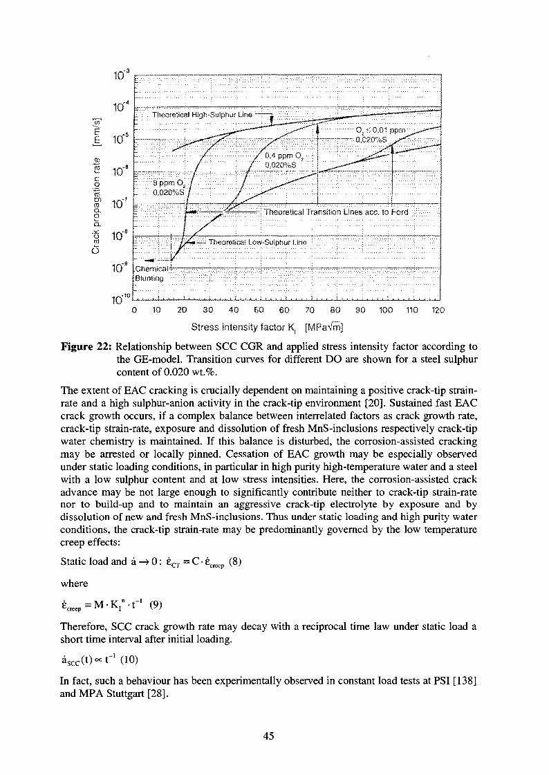
theoretical transition Lines
- Theurwt'raai I ow-Suiphur t mo
10 20 30 40 60 60 70 80 SO
Stress intensity factor K. [MPaVm]
100 110 120
Figure 22: Relationship between SCC CGR and applied stress intensity factor according tothe GE-model. Transition curves for different DO are shown for a steel sulphurcontent of 0.020 wt.%.
The extent of EAC cracking is crucially dependent on maintaining a positive crack-tip strain-rate and a high sulphur-anion activity in the crack-tip environment [20]. Sustained fast EACcrack growth occurs, if a complex balance between interrelated factors as crack growth rate,crack-tip strain-rate, exposure and dissolution of fresh MnS-inclusions respectively crack-tipwater chemistry is maintained. If this balance is disturbed, the corrosion-assisted crackingmay be arrested or locally pinned. Cessation of EAC growth may be especially observedunder static loading conditions, in particular in high purity high-temperature water and a steelwith a low sulphur content and at low stress intensities. Here, the corrosion-assisted crackadvance may be not large enough to significantly contribute neither to crack-tip strain-ratenor to build-up and to maintain an aggressive crack-tip electrolyte by exposure and bydissolution of new and fresh MnS-inclusions. Thus under static loading and high purity waterconditions, the crack-tip strain-rate may be predominantly governed by the low temperaturecreep effects:
Static load and a —> 0: £CT = C-£creep(8)
where
= M-K In - r 1 (9)
Therefore, SCC crack growth rate may decay with a reciprocal time law under static load ashort time interval after initial loading.
asccC^oct"1 (10)
In fact, such a behaviour has been experimentally observed in constant load tests at PSI [138]and MPA Stuttgart [28].
45
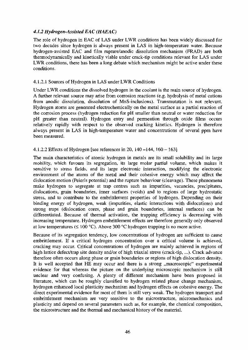
4.1.2 Hydrogen-Assisted EAC (HAEAC)
The role of hydrogen in EAC of LAS under LWR conditions has been widely discussed fortwo decades since hydrogen is always present in LAS in high-temperature water. Becausehydrogen-assisted EAC and film rupture/anodic dissolution mechanism (FRAD) are boththermodynamically and kinetically viable under crack-tip conditions relevant for LAS underLWR conditions, there has been a long debate which mechanism might be active under theseconditions.
4.1.2.1 Sources of Hydrogen in LAS under LWR Conditions
Under LWR conditions the dissolved hydrogen in the coolant is the main source of hydrogen.A further relevant source may arise from corrosion reactions (e.g. hydrolysis of metal cationsfrom anodic dissolution, dissolution of MnS-inclusions). Transmutation is not relevant.Hydrogen atoms are generated electrochemically on the metal surface as a partial reaction ofthe corrosion process (hydrogen reduction for pH smaller than neutral or water reduction forpH greater than neutral). Hydrogen entry and permeation through oxide films occursrelatively rapidly with respect to the observed cracking kinetics. Hydrogen is thereforealways present in LAS in high-temperature water and concentrations of several ppm havebeen measured.
4.1.2.2 Effects of Hydrogen [see references in 20, 140 -144, 160 - 163]
The main characteristics of atomic hydrogen in metals are its small solubility and its largemobility, which favours its segregation, its large molar partial volume, which makes itsensitive to stress fields, and its large electronic interaction, modifying the electronicenvironment of the atoms of the metal and their cohesive energy which may affect thedislocation motion (Peierls potential) and the rupture behaviour (cleavage). These phenomenamake hydrogen to segregate at trap centres such as impurities, vacancies, precipitates,dislocations, grain boundaries, inner surfaces (voids) and to regions of large hydrostaticstress, and to contribute to the embrittlement properties of hydrogen. Depending on theirbinding energy of hydrogen, weak (impurities, elastic interactions with dislocations) andstrong traps (dislocation cores, phase and grain boundaries, internal surfaces) can bedifferentiated. Because of thermal activation, the trapping efficiency is decreasing withincreasing temperature. Hydrogen embrittlement effects are therefore generally only observedat low temperatures (< 100 °C). Above 300 °C hydrogen trapping is no more active.
Because of its segregation tendency, low concentrations of hydrogen are sufficient to causeembrittlement. If a critical hydrogen concentration over a critical volume is achieved,cracking may occur. Critical concentrations of hydrogen are mainly achieved in regions ofhigh lattice defect/trap site density and/or of high triaxial stress (crack-tip, ...). Crack advancetherefore often occurs along phase or grain boundaries or regions of high dislocation density.It is well accepted that HE may occur and there is a strong ,,macroscopic" experimentalevidence for that whereas the picture on the underlying microscopic mechanism is stillunclear and very confusing. A plenty of different mechanism have been proposed inliterature, which can be roughly classified to hydrogen related phase change mechanism,hydrogen enhanced local plasticity mechanism and hydrogen effects on cohesive energy. Thedirect experimental evidence for most of them is still very weak. The hydrogen transport andembrittlement mechanism are very sensitive to the microstructure, micromechanics andplasticity and depend on several parameters such as, for example, the chemical composition,the microstructure and the thermal and mechanical history of the material.
46
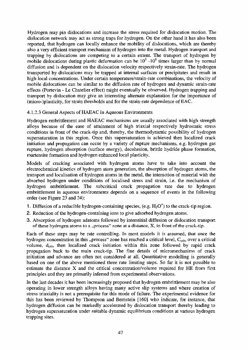
Hydrogen may pin dislocations and increase the stress required for dislocation motion. Thedislocation network may act as strong traps for hydrogen. On the other hand it has also beenreported, that hydrogen can locally enhance the mobility of dislocations, which are therebyalso a very efficient transport mechanism of hydrogen into the metal. Hydrogen transport andtrapping by dislocations are competing to a certain extent. The transport of hydrogen bymobile dislocations during plastic deformation can be 103 -106 times larger than by normaldiffusion and is dependent on the dislocation velocity respectively strain-rate. The hydrogentransported by dislocations may be trapped at internal surfaces or precipitates and result inhigh local concentrations. Under certain temperature/strain-rate combinations, the velocity ofmobile dislocations can be similar to the diffusion rate of hydrogen and dynamic strain-rateeffects (Portevin - Le Chatelier effect) might eventually be observed. Hydrogen trapping andtransport by dislocation may give an interesting alternate explanation for the importance of(micro-)plasticity, for strain thresholds and for the strain-rate dependence of EAC.
4.1.2.3 General Aspects of HAEAC in Aqueous Environments
Hydrogen embrittlement and HAEAC mechanisms are usually associated with high strengthalloys because of the ease of attainment of high triaxial respectively hydrostatic stressconditions in front of the crack-tip and, thereby, the thermodynamic possibility of hydrogensupersaturation in this region. Once this supersaturation is achieved then localized crackinitiation and propagation can occur by a variety of rupture mechanisms, e.g. hydrogen gasrupture, hydrogen absorption (surface energy), decohesion, brittle hydride phase formation,martensite formation and hydrogen enhanced local plasticity.
Models of cracking associated with hydrogen atoms have to take into account theelectrochemical kinetics of hydrogen atom generation, the absorption of hydrogen atoms, thetransport and localisation of hydrogen atoms in the metal, the interaction of material with theabsorbed hydrogen under conditions of localised stress and strain, i.e. the mechanism ofhydrogen embrittlement. The subcritical crack propagation rate due to hydrogenembrittlement in aqueous environments depends on a sequence of events in the followingorder (see Figure 23 and 24):
1. Diffusion of a reducible hydrogen-containing species, (e.g. H3O"1") to the crack-tip region.
2. Reduction of the hydrogen-containing ions to give adsorbed hydrogen atoms.
3. Absorption of hydrogen adatoms followed by interstitial diffusion or dislocation transportof these hydrogen atoms to a ,,process" zone at a distance, X, in front of the crack-tip.
Each of these steps may be rate controlling. In most models it is assumed, that once thehydrogen concentration in this ,,process" zone has reached a critical level, Ccrit, over a criticalvolume, dent, then localized crack initiation within this zone followed by rapid crackpropagation back to the main crack-tip. The fine details of micromechanims of crackinitiation and advance are often not considered at all. Quantitative modelling is generallybased on one of the above mentioned three rate limiting steps. So far it is not possible toestimate the distance X and the critical concentration/volume required for HE from firstprinciples and they are primarily inferred from experimental observations.
In the last decades it has been increasingly proposed that hydrogen embrittlement may be alsooperating in lower strength alloys having many active slip systems and where creation ofstress triaxiality is not a prerequisite for this mode of failure. The experimental evidence forthis has been reviewed by Thompson and Bernstein [160] who indicate, for instance, thathydrogen diffusion can be markedly accelerated by dislocation transport thereby leading tohydrogen supersaturation under suitable dynamic equilibrium conditions at various hydrogentrapping sites.
47
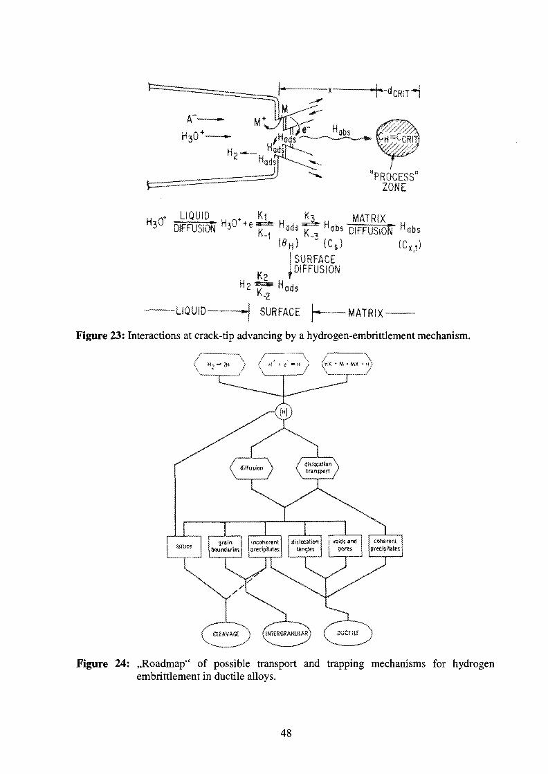
"PROCESS"ZONE
LIQUID^DIFFUSION
MATRIX
H
I SURFACE^DIFFUSION
-LIQUID- SURFACE M ATRIX
Figure 23: Interactions at crack-tip advancing by a hydrogen-embrittlement mechanism.
( H,« »f\
) (nx • M • MX • H)/ \ /
( ClfAVAa ) (1NIE8CSAMUUR
Figure 24: ,,Roadmap" of possible transport and trapping mechanisms for hydrogenembrittlement in ductile alloys.
48
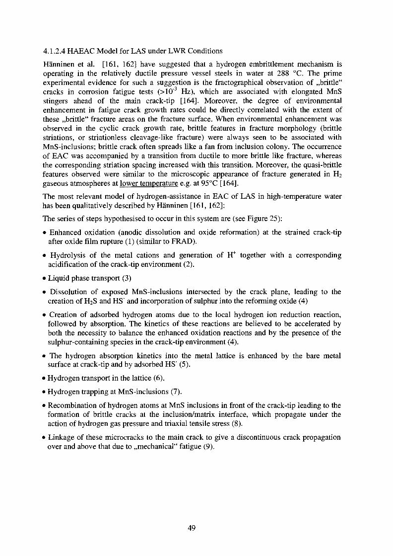
4.1.2.4 HAEAC Model for LAS under LWR Conditions
Hanninen et al. [161, 162] have suggested that a hydrogen embrittlement mechanism isoperating in the relatively ductile pressure vessel steels in water at 288 °C. The primeexperimental evidence for such a suggestion is the fractographical observation of ,,brittle"cracks in corrosion fatigue tests (>10~3 Hz), which are associated with elongated MnSstingers ahead of the main crack-tip [164]. Moreover, the degree of environmentalenhancement in fatigue crack growth rates could be directly correlated with the extent ofthese ,,brittle" fracture areas on the fracture surface. When environmental enhancement wasobserved in the cyclic crack growth rate, brittle features in fracture morphology (brittlestriations, or striationless cleavage-like fracture) were always seen to be associated withMnS-inclusions; brittle crack often spreads like a fan from inclusion colony. The occurrenceof EAC was accompanied by a transition from ductile to more brittle like fracture, whereasthe corresponding striation spacing increased with this transition. Moreover, the quasi-brittlefeatures observed were similar to the microscopic appearance of fracture generated in H2gaseous atmospheres at lower temperature e.g. at 95 °C [164].
The most relevant model of hydrogen-assistance in EAC of LAS in high-temperature waterhas been qualitatively described by Hanninen [161, 162]:
The series of steps hypothesised to occur in this system are (see Figure 25):
• Enhanced oxidation (anodic dissolution and oxide reformation) at the strained crack-tipafter oxide film rupture (1) (similar to FRAD).
• Hydrolysis of the metal cations and generation of H* together with a correspondingacidification of the crack-tip environment (2).
• Liquid phase transport (3)
• Dissolution of exposed MnS-inclusions intersected by the crack plane, leading to thecreation of H2S and HS" and incorporation of sulphur into the reforming oxide (4)
• Creation of adsorbed hydrogen atoms due to the local hydrogen ion reduction reaction,followed by absorption. The kinetics of these reactions are believed to be accelerated byboth the necessity to balance the enhanced oxidation reactions and by the presence of thesulphur-containing species in the crack-tip environment (4).
• The hydrogen absorption kinetics into the metal lattice is enhanced by the bare metalsurface at crack-tip and by adsorbed HS" (5).
• Hydrogen transport in the lattice (6).
• Hydrogen trapping at MnS-inclusions (7).
• Recombination of hydrogen atoms at MnS inclusions in front of the crack-tip leading to theformation of brittle cracks at the inclusion/matrix interface, which propagate under theaction of hydrogen gas pressure and triaxial tensile stress (8).
• Linkage of these microcracks to the main crack to give a discontinuous crack propagationover and above that due to ,,mechanical" fatigue (9).
49
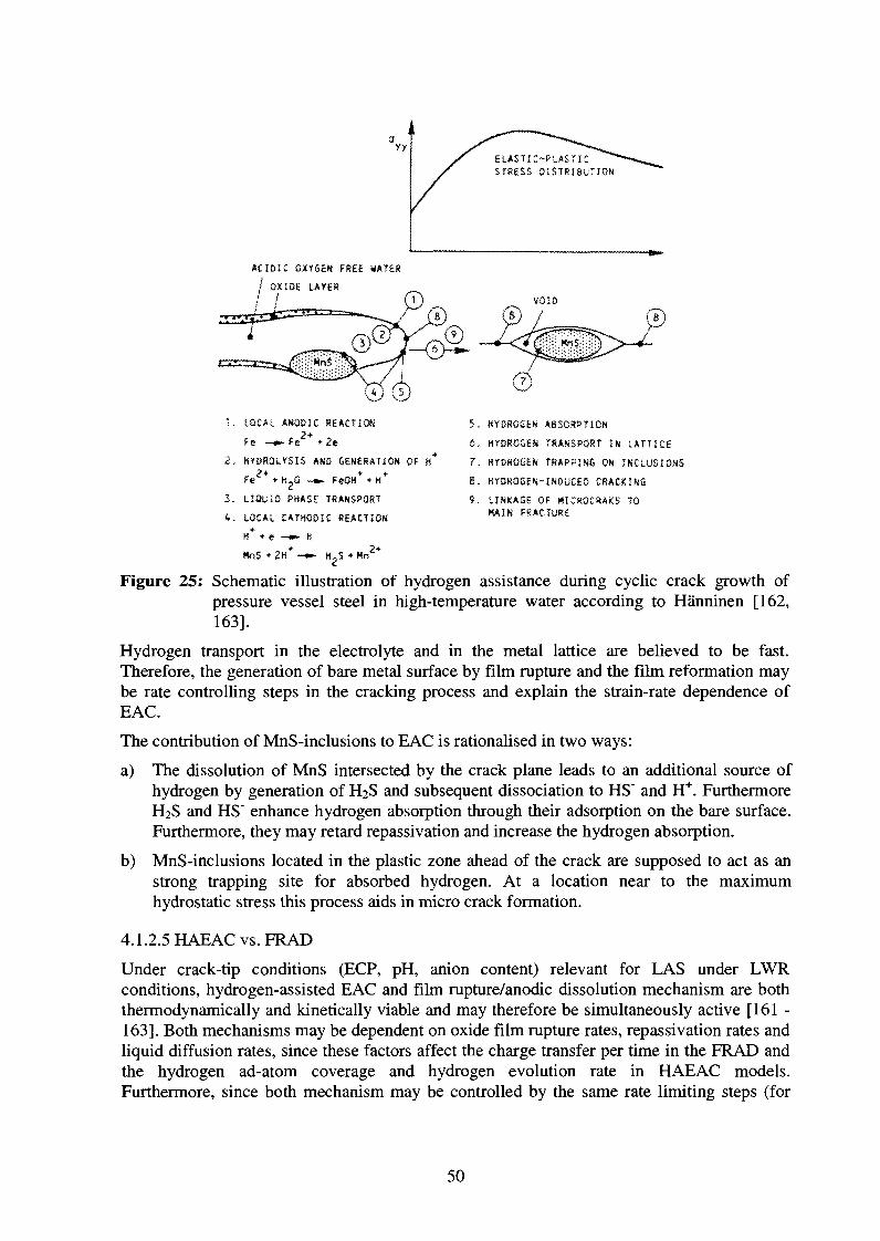
ELASTIC-PLASTICSTRESS DISTRIBUTION
ACIDIC OXYGEN FREE WATER
/ OX1O6 LAYER
/
LOCAL ANODIC REACTION2+ . ,
Fe Fe
Z. HYDROLYSIS AND GENERATION OF H*
Fe • tljO -m- FeOH+ + H*
3. L28U1D PHASE TRANSPORT
4. LOCAL CATHOOIC REACTION
H+ + e -*» H2*
3. KYD30SSX A8S0SPT10N
6. HYDROGEN TRANSPORT IN LATTICE
?. HYDROGEN TRAPPING ON INCLUSIONS
S. HYDROGEN-INDUCED CRACKING
9. LINKA5E OF HICRQCRAKS TOMAIN FRACTURE
HnS + 2H -•- H?S • Mn'
Figure 25: Schematic illustration of hydrogen assistance during cyclic crack growth ofpressure vessel steel in high-temperature water according to Hanninen [162,163].
Hydrogen transport in the electrolyte and in the metal lattice are believed to be fast.Therefore, the generation of bare metal surface by film rupture and the film reformation maybe rate controlling steps in the cracking process and explain the strain-rate dependence ofEAC.
The contribution of MnS-inclusions to EAC is rationalised in two ways:
a) The dissolution of MnS intersected by the crack plane leads to an additional source ofhydrogen by generation of H2S and subsequent dissociation to HS" and H+. FurthermoreH2S and HS" enhance hydrogen absorption through their adsorption on the bare surface.Furthermore, they may retard repassivation and increase the hydrogen absorption.
b) MnS-inclusions located in the plastic zone ahead of the crack are supposed to act as anstrong trapping site for absorbed hydrogen. At a location near to the maximumhydrostatic stress this process aids in micro crack formation.
4.1.2.5 HAEAC vs. FRAD
Under crack-tip conditions (ECP, pH, anion content) relevant for LAS under LWRconditions, hydrogen-assisted EAC and film rupture/anodic dissolution mechanism are boththermodynamically and kinetically viable and may therefore be simultaneously active [161 -163]. Both mechanisms may be dependent on oxide film rupture rates, repassivation rates andliquid diffusion rates, since these factors affect the charge transfer per time in the FRAD andthe hydrogen ad-atom coverage and hydrogen evolution rate in HAEAC models.Furthermore, since both mechanism may be controlled by the same rate limiting steps (for
50
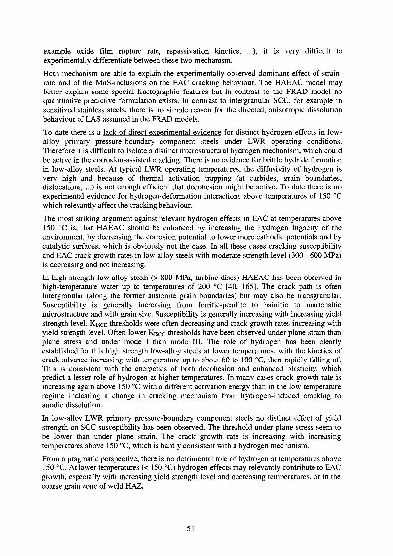
example oxide film rupture rate, repassivation kinetics, ...), it is very difficult toexperimentally differentiate between these two mechanism.
Both mechanism are able to explain the experimentally observed dominant effect of strain-rate and of the MnS-inclusions on the EAC cracking behaviour. The HAEAC model maybetter explain some special fractographic features but in contrast to the FRAD model noquantitative predictive formulation exists. In contrast to intergranular SCC, for example insensitized stainless steels, there is no simple reason for the directed, anisotropic dissolutionbehaviour of LAS assumed in the FRAD models.
To date there is a lack of direct experimental evidence for distinct hydrogen effects in low-alloy primary pressure-boundary component steels under LWR operating conditions.Therefore it is difficult to isolate a distinct microstructural hydrogen mechanism, which couldbe active in the corrosion-assisted cracking. There is no evidence for brittle hydride formationin low-alloy steels. At typical LWR operating temperatures, the diffusivity of hydrogen isvery high and because of thermal activation trapping (at carbides, grain boundaries,dislocations, ...) is not enough efficient that decohesion might be active. To date there is noexperimental evidence for hydrogen-deformation interactions above temperatures of 150 °Cwhich relevantly affect the cracking behaviour.
The most striking argument against relevant hydrogen effects in EAC at temperatures above150 °C is, that HAEAC should be enhanced by increasing the hydrogen fugacity of theenvironment, by decreasing the corrosion potential to lower more cathodic potentials and bycatalytic surfaces, which is obviously not the case. In all these cases cracking susceptibilityand EAC crack growth rates in low-alloy steels with moderate strength level (300 - 600 MPa)is decreasing and not increasing.
In high strength low-alloy steels (> 800 MPa, turbine discs) HAEAC has been observed inhigh-temperature water up to temperatures of 200 °C [40, 165]. The crack path is oftenintergranular (along the former austenite grain boundaries) but may also be transgranular.Susceptibility is generally increasing from ferritic-pearlitc to bainitic to martensiticmicrostructure and with grain size. Susceptibility is generally increasing with increasing yieldstrength level. KKCC thresholds were often decreasing and crack growth rates increasing withyield strength level. Often lower Kiscc thresholds have been observed under plane strain thanplane stress and under mode I than mode HI. The role of hydrogen has been clearlyestablished for this high strength low-alloy steels at lower temperatures, with the kinetics ofcrack advance increasing with temperature up to about 60 to 100 °C, then rapidly falling of.This is consistent with the energetics of both decohesion and enhanced plasticity, whichpredict a lesser role of hydrogen at higher temperatures. In many cases crack growth rate isincreasing again above 150 °C with a different activation energy than in the low temperatureregime indicating a change in cracking mechanism from hydrogen-induced cracking toanodic dissolution.
In low-alloy LWR primary pressure-boundary component steels no distinct effect of yieldstrength on SCC susceptibility has been observed. The threshold under plane stress seem tobe lower than under plane strain. The crack growth rate is increasing with increasingtemperatures above 150 °C, which is hardly consistent with a hydrogen mechanism.
From a pragmatic perspective, there is no detrimental role of hydrogen at temperatures above150 °C. At lower temperatures (< 150 °C) hydrogen effects may relevantly contribute to EACgrowth, especially with increasing yield strength level and decreasing temperatures, or in thecoarse grain zone of weld HAZ.
51

4.1.3 Dynamic Strain Ageing (DSA)
4.1.3.1 Background
Atkinson et al. [132 - 134] have suggested recently that dynamic strain ageing (DSA) in steelmay be very influential in determining both EAC cracking strain-rate sensivity and itstemperature dependence [135]. It provides an alternate possible explanation for strain-ratethresholds and more significantly, it may offer an explanation for the cracking peak atintermediate temperatures and rationalize the scattered data in this temperature range (seealso Section 3.3.1). Furthermore it may provide a possible explanation for the observed quasi-cleavage fracture surface observed in EAC.
There is now increasing experimental evidence that DSA may play an important role on EACunder certain conditions:
Coincidence of temperature and strain-rate between DSA hardening and susceptibility toEAC of RPV steels in SSRT and SRL tests under low flow oxygenated high-temperaturewater conditions has been observed [132- 135] (see Figure 26 and 27).
The loss of ductility (RA) in SSRT tests in low flow oxygenated high-temperature water andin air increased with increasing free nitrogen content, confirming that DSA may be furthercontributing factor for EAC [132-135].
ooX
ou—i-amcr
HAInH2O*100ppbG2RA in H2O200ppb O2RA in M2O4€0ppb O2RA In H2O€0Qppb 02RA in MtT.Strength la Alf
esu
600
m
£00
L3S0
enc
m
-30Q
50 100 200 250 300 350 400Temperaiurs 8C
Figure 26: Coincidence of susceptibility of LAS to SICC in SSRT-tests (minimum inreduction of area) in high-temperature water with DSA behavior (maximum oftensile strength) in air in terms of temperature and strain-rate [133-135].
4.1.3.2 Phenomenological and Microscopical Features of DSA
DSA may be observed in susceptible LAS during plastic straining at sufficiently slow strain-rates (< = 10'2 s"1) in the temperature range from 100 °C to 350 °C. DSA in LAS is associatedwith diffusion of interstitial species such as C and N atoms to the core region of dislocationsand their immobilization. The DSA effects increase with increasing concentration of free,interstitial N and C and are most pronounced if the diffusion rate of C/N and the dislocation
52
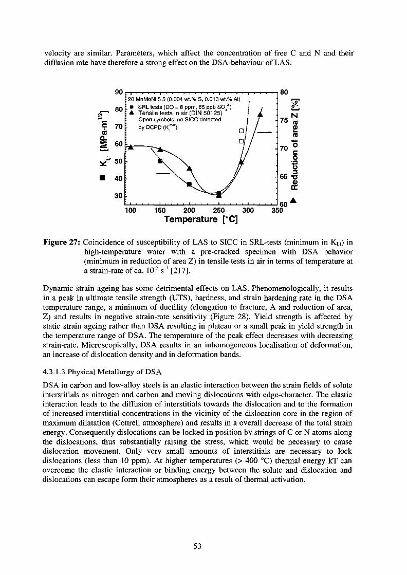
velocity are similar. Parameters, which affect the concentration of free C and N and theirdiffusion rate have therefore a strong effect on the DSA-behaviour of LAS.
90
8 0
" I 70QsQ. 60
50
40
30
20 MnMoNi 5 5 (0.004 wt.% S, 0.013 wt.% Al)I SRL tests (DO = 8 ppm, 65 ppb SO 2")^ Tensile tests in air (DIN 50125)
Open symbols: no SICC detectedby DCPD ( O
80
75
70
65
£(0
"5coIIDC
100 150 200 250 300
Temperature [°C]
60350
Figure 27: Coincidence of susceptibility of LAS to SICC in SRL-tests (minimum in K14) inhigh-temperature water with a pre-cracked specimen with DSA behavior(minimum in reduction of area Z) in tensile tests in air in terms of temperature at
[217].a strain-rate of ca. 10"5 s"1
Dynamic strain ageing has some detrimental effects on LAS. Phenomenologically, it resultsin a peak in ultimate tensile strength (UTS), hardness, and strain hardening rate in the DSAtemperature range, a minimum of ductility (elongation to fracture, A and reduction of area,Z) and results in negative strain-rate sensitivity (Figure 28). Yield strength is affected bystatic strain ageing rather than DSA resulting in plateau or a small peak in yield strength inthe temperature range of DSA. The temperature of the peak effect decreases with decreasingstrain-rate. Microscopically, DSA results in an inhomogeneous localisation of deformation,an increase of dislocation density and in deformation bands.
4.3.1.3 Physical Metallurgy of DSA
DSA in carbon and low-alloy steels is an elastic interaction between the strain fields of soluteinterstitials as nitrogen and carbon and moving dislocations with edge-character. The elasticinteraction leads to the diffusion of interstitials towards the dislocation and to the formationof increased interstitial concentrations in the vicinity of the dislocation core in the region ofmaximum dilatation (Cottrell atmosphere) and results in a overall decrease of the total strainenergy. Consequently dislocations can be locked in position by strings of C or N atoms alongthe dislocations, thus substantially raising the stress, which would be necessary to causedislocation movement. Only very small amounts of interstitials are necessary to lockdislocations (less than 10 ppm). At higher temperatures (> 400 °C) thermal energy kT canovercome the elastic interaction or binding energy between the solute and dislocation anddislocations can escape form their atmospheres as a result of thermal activation.
53
IPaJ
reng
t
W
ensi
l650
640
630
620
610
600
dl/dt = 0.03 mm/min
•
\ i\j
80
0 50 100 150 200 250 300 350
Temperature [°C]
cfe^/dt = 1E-5 sdl/dt = 0.03 m/min
50 100 150 200 250 300 350
Temperature [°C]
650
10
NcQ
CO
"5o
<DCC
10-6
Strain rate de, Vdt [s ]T6Cn
10"b 10"1 10"3 10"2
Strain rate de /dt [s~1]tech
CO
|
COCO
£55
600
550
500
4sn
50O
480
480
470
•
A,
7 0.8 0.9 10 1.1
,-Jr /
V
12
^ 2.55E-6 s " y ~ - <
/y^C 9-43E-5S
9.26E-4 s"!
T = 200 °C• i i i r . . . . .
•s2c
CO
10"21 \J
3
10
10"4
10'5
o
e
e
- e
No serrationsSerrationsYield plateau
e
e
no plateau
o
e/
/
o / ••
20 MnMoNi 5 5 (B)
/ // • / O O 1
/
o
» oOooo •,
0.5 1.0 1.5 2.0 2.5 3.0 3.5 4.0 4.5 5.0
Strain e. u [%10 50 100 150 200 250 300 350 400
Temperature [°C]
Figure 28: Typical features of DSA in tensile tests in air with a susceptible RPV steel(20MnMoNi 5 5 , 30 ppm Nfree): Maximum/minimum in Rm/Z at intermediatetemperatures, negative strain-rate sensivity, serrations in stress strain curve[216].
When the temperature is raised into the DSA region (typically 100 - 350 °C), interstitials candiffuse during deformation and can form atmospheres around dislocations generated duringdeformation. The dislocations generated are quickly pinned so that others must be generatedto allow deformation to continue. As a result, the dislocation density at a given strain ishigher than when the straining is done outside the DSA range. The repeated breakaway andrepining of mobile dislocations by the interstitials was the original explanation for the
54

serrations in the stress-strain curve. The alternate explanation is that once carbon and nitrogenatmospheres are formed, the dislocations remain locked, and the serrated yield phenomenaarise from the generation and movement of newly formed dislocations, which are thensuddenly pinned. The DSA effect respectively the pinning of dislocations is at maximum, ifthe diffusion rate (which is dependent on the temperature) of the free interstitials and thedislocation velocity (which is dependent on loading and strain-rate respectively frequency)are similar. This is schematically shown in Figure 29. At low strain-rate or frequency,diffusion of the interstitials is faster than the dislocations, at high strain-rates dislocations aretoo fast to be pined by the interstitials, so in both cases there is no significant DSA-effect.The maximum is a function of temperature or strain-rate. For higher temperatures maximumDSA-peak is shifted to higher strain-rates. With increasing strain-rate DSA-peak is shifted tohigher temperatures.
1118to
CompletePassivation >
/ 2« \
/Corrosion Fatigue \/ o r \
/ Stress Corrosion \/ Cracking \
/ by Slip/Dissolution %
fV^ ' Mechanical
^k Fracture
o
§ 1P. O
SlowLow Frequency
Log Strait? RateLog Cyclic Frequency
FastHigh Frequency
Figure 29: Correlation between frequency/strain-rate and DSA or EAC response.
4.1.3.4 The Metallurgy of DSA
In ferrite N and C have similar diffusion coefficients and they are producing a nearlyidentical lattice misfit strain, thus, these two elements are expected to produce nearly similarDSA effects in LAS. Therefore, in general, the effects produced by C and N can beconsidered as additive. At room temperature, the residual solubility of N in ferrite is about100 times greater than that of C - N solubility in steel is higher at all temperatures than thatof C. It is generally assumed that N, rather than C, is mainly responsible for DSA. However,at higher temperatures in the DSA range the increasing solubility of carbon may cause DSAeven in the absence of N.
The concentration of free interstitial C and N strongly depend on the steel making (killing) orwelding process, the thermal history or heat-treatment (annealing-, PWHT- or stress relievingtemperature) and on the chemical composition (Ctot, Ntot, Al, V, Ti, Cr, Mo, O, Mn ...) of thesteel. Alloying elements, which have a strong affinity to N or C, such as Al, Cr and Mo, andform nitrides or carbides may result in a reduction of the residual concentration of free C andN. Parameters, which would affect the interstitial diffusion in dilute alloys might also affectthe DSA-behaviour of LAS. The measured activation energy for the onset of serrations in the
55

stress-strain curve is not sensitive to the microstructure or composition of steel. Theexemption being the Mn content which seems to influence the diffusion process of N and Cby forming Mn-N and Mn-C pairs increasing thus the activation energy for the diffusionprocess [135]. Large differences in the activation energy for the disappearance of DSAreported suggest that it is also a function of steel composition.
Silicon-killed vs. Al-killed low-alloy steels:
Silicon killed, air poured carbon or low-alloy steels show a much more pronounced DSAeffect than aluminium killed vacuum ladle degassed steels, since in aluminium killed steels,aluminium nitrides are formed and the remaining free interstitial nitrogen content is very low.The Al/N-ratio is therefore an important parameter governing the free nitrogen content andthe resulting DSA effect.
Weld material:
During the welding process uptake of small amounts of oxygen and nitrogen can occur. Weldmetal often have a very little aluminium- but high oxygen-contents. Because of its very highaffinity to oxygen, aluminium fist combines to oxygen (aluminium oxide precipitates) inwelds, which reduces the beneficial effect of the aluminium. During fast cooling afterwelding, incomplete precipitation of carbides and nitrides occurs resulting in an increased oreven supersaturated concentration of free C and N in the as-welded condition. Theprecipitation of carbides during PWHT further reduces the concentration of free C and N.The PWHT-temperarure is detrimental. The free C and N decrease with increasing annealingtemperature because of precipitation of carbides and nitrides.
Welds might reveal increased concentrations of interstitial N and therefore be moresusceptible to EAC in the DSA-temperature /strain-rate range than generally thought so far.LFCF crack growth tests in high-temperature water with weld materials have been performedunder temperature-strain-rate conditions (> 250 °C, > 10'3 Hz) where DSA is absent or onlymoderately active. The better resistance of the weld material under these conditions has beenmainly attributed to the different morphology and chemical composition of MnS-inclusionsin the welds (very small spherical inclusions).
Weld HAZ material:
The free carbon content in low-alloy steels can strongly vary depending on the heat treatmentand on chemical composition (Ctot, Cr, Mo, V, ...). Alloying elements, which have a strongtendency to form carbides as Cr or Mo may also affect the residual interstitial carbon content.In the heat-affected zone near to the fusion line, with high peak temperatures slightly belowthe melting point (partial) dissolution of carbides and (incomplete) re-precipitation duringsubsequent cooling occurs, which can result in a supersaturated state. During the followingPWHT (stress relieving) precipitation of further carbides occurs. The interstitial carbon isstrongly dependent on the stability of the carbides (chemical composition), on the peaktemperature, heating and cooling rates and on the PWHT-treatments applied. The most severeDSA-effects are expected for materials in the as-welded condition without PWHT (e.g. repairwelding).
The free carbon and nitrogen content are not specified in the relevant nuclear guidelines andregulations (KTA, ASME BVP) for the low-alloy LWR primary pressure-boundarycomponent steels and can strongly vary from steel to steel, steel to weld and within weldHAZ resulting in a different EAC response in the DSA-temperature/strain-rate range. Theconcentrations can vary between 0 ppm and a supersaturated state well above the solubilitylimit. Differences in free nitrogen and carbon content of otherwise identical or similar low-alloy steels may be one important further reason for the relevant scatter of EAC crack growth
56
rate data, and especially for the sometimes-observed different trends in temperaturedependence of EAC.
4.1.3.5 Possible Interaction between DSA and EAC in LAS
The role of DSA in EAC has not been studied much. However, the EAC data stronglysuggest that the susceptibility of LAS to EAC coincides with DSA behaviour, in terms oftemperature and strain-rate [133 -135]. Environment-assisted cracking behaviour of LAS iscontrolled by various mechanical, environmental and material parameters. In EAC, DSA isespecially important in dynamic crack-tip plasticity behaviour such as dynamic loading ordevelopment of creep strain. The crack-tip strain-rate is an important parameter in controllingEAC (see Section 4.1.1). DSA affects the yield strength, strain hardening exponent and creeprate, which are important factors affecting the crack-tip strain and strain-rate. DSA may resultin a higher crack-tip strain and strain-rate than in a material, which is not susceptible to DSA.Microscopically, DSA results in an inhomogeneous localisation of deformation, an increaseof dislocation density and increase in planar deformation [135]. These factors can result inreduction of the local fracture toughness and favour brittle crack extension, but also in themechanical rupture of the protective oxide film and therefore crack advance by anodicdissolution/hydrogen embrittlement mechanism. Therefore DSA may synergistically interactwith anodic dissolution and hydrogen embrittlement to increase EAC cracking susceptibility.
EAC in LAS has been observed under temperature/stain rate conditions or in materials, whereno or only minor DSA-effects were present. DSA is therefore not a pre-requisite for EAC andbest regarded as an additional contribution to EAC growth process.
57

4.2 Local Crack-Tip Chemistry and Mass Transport
EAC crack initiation and growth from incipient cracks are governed by the local mechanical,metallurgical and environmental crack-tip conditions, e.g. for a given material primarily bythe crack-tip strain-rate and the activity of chloride and sulphur-anions and the rjH in thecrack-tip environment [48]. This local factors are governed by a system of interrelatedcorrosion system parameters such as the applied load and load ratio, strain/loading rate, theECP or dissolved oxygen content, the flow rate across the crack mouth, the bulkconcentration of specific anionic impurities as SO42" and Cl" and the steel MnS-inclusioncontent and morphology.
The local crack-tip water chemistry is normally more aggressive than the corresponding bulkwater chemistry outside the crack. But generally, only the bulk water chemistry is known anddirect information on crack-tip water chemistry arises primarily from modelling and fromnew in-situ experimental techniques (crack-tip microsampling, crack-tip ECP measurement).
The following sections qualitatively outline, how the local crack-tip chemistry is related tothe known bulk water chemistry outside the crack by mass transport mechanism and to localmicrochemistry by the dissolution of MnS-inclusions. The discussion is primarily focused toBWR conditions and is based on the film rupture/anodic dissolution mechanism. Crack andcrevice chemistry have been the topic of many reviews [166 - 168]. Models for crack/crevice(electro-)chemistry and their potential application to LWR conditions have been recentlydiscussed in [166,168].
The basic concepts and fundamental processes for the evolution of the occluded crackchemistry are discussed in Section 4.2.1. Typical crack-tip conditions (potential, pH,conductivity, impurity concentrations) in LAS under LWR conditions are outlined in Section4.2.2. Finally, some important aspects of crack (electro-) chemistry (ECP, impurities, MnS-inclusion, flow rate) are further discussed in Section 4.2.3.
4.2.1 Basic Concepts of Crack Chemistry in Low-Alloy Steels under LWR Conditions
Figure 30 shows the basic concepts of crack chemistry and electrochemistry for EAC in LASunder LWR conditions, which is based on the film rupture/anodic dissolution mechanism.This qualitative picture of crack (electro-)chemistry is primarily based on experimentalobservations. Currently, only very simplified and therefore limited models exist for LASunder LWR conditions [168].
Bulk and crack-tip environment are coupled by mass transport processes (diffusion,migration, convection) and charge conservation. The impurity concentration in the crackenclave is dependent on its bulk concentration outside the crack enclave, itsproduction/depletion rate by homogeneous or heterogeneous reactions in the crack enclave(e.g. MnS-dissolution, hydrolysis of metal cations, precipitation reactions, electrochemicalreactions at crack surface) and by its transport into or out of the crack enclave by diffusion,migration and convection. Many of these processes are dependent on one or several factorssuch as the potential, pH, concentration, which may be a function of location in the crackenclave.
58

_ cr, sol; OK
2H* + 2e: - • H2
4 CAVflux « diffusion + 41-driven + convecficai
Figure 30: Schematic of crack electro- and water chemistry showing the differential aerationcell at the crack mouth (reaction 3 and 4) that establishes the crack-tip chemistryand the local microcell (reaction 1 and 2) associated with metal dissolution andcrack advance. Because of the high ohmic resistance of the electrolyte, there is nodirect coupling of electronic currents between these two cells. The potentialgradient between the aerated crack mouth (+ 0.1 VSHE) and the de-aerated crack-tip (- 0.5 VSHE) results in an additional flux of anions/cations into/out of the crackenclave and an enrichments of anions and pH-shifts in the crack-tip environmentin the case of non-OH~anions in the bulk environment. (In the case of low-alloysteels, Ni/Ni2+ has to be replaced by Fe/Fe2+).
Even under relatively pure bulk water chemistry conditions, an aggressive occluded waterchemistry can be formed in cracks and crevices under the action of concentration (differentialaeration) or thermal cells or from outright boiling. Such occluded cells only require arestricted crevice geometry. For LWR low-alloy steel primary pressure-boundary componentsonly the differential aeration cell is of relevance.
In oxygenated high-temperature water (BWR conditions) a differential aeration cell is formedin the crack mouth region, since oxygen reduction is faster than its diffusion. Dynamic crack-tip straining may additionally result in oxide film rupture and the formation of a dissolutioncell at crack-tip. Both cells may exist without the existence of the other one. The evolution ofthe differential aeration cell, for example, only requires a restricted crevice geometry.Because of the limited conductivity under typical LWR conditions and the resulting highohmic potential drops, the crack-tip (dissolution cell) and crack mouth electrochemistry(differential aeration cell) are only coupled by mass transport but not by direct electroniccoupling.
59

4.2.2 Differential Aeration Cell at the Crack Mouth
Oxygen reduction kinetics on oxide films is fast with respect to oxygen mass transport bydiffusion in high-temperature water. Therefore, in a high aspect ratio cracks with restrictedmass transport, almost all oxygen is consumed over a short distance in the crack mouthregion resulting in a built-up of a differential aeration cell (oxygen concentration cell). Theresulting potential drop in this differential aeration cell and the additional mass transport bymigration were important factors for the evolution of the corresponding crevice and crack-tipwater chemistry. The potential drop in the crack mouth is acting as a pump for anionicimpurities in the bulk environment towards the crack-tip and retains anionic impuritiesgenerated by (electro-)chemical reactions (dissolution of MnS-inclusions) in the crack-tipenvironment. If the bulk reactor water contains specific anionic impurities as SO4
2, Cl", themigration of these impurities can result in a pH-shift. The dissolution of MnS-inclusions andthe hydrolysis of metal cations generated by anodic dissolution may be further reasons forpH-shifts under these conditions. The potential gradient and its effect on the evolution of thecrack-tip chemistry is decreasing with decreasing bulk oxygen content. Under BWR/HWC orPWR conditions, there is only a small or virtually no potential gradient between the crackmouth and crack-tip and mass transport is governed by diffusion only.
4.2.3 Dissolution Cell at the Crack-Tip
Mechanical straining results in the rupture of the protective oxide film at the crack-tip and inexposure of fresh bare metal to the de-aerated crack-tip electrolyte and in crack growth byanodic dissolution. The crack growth is stopped by the reformation of the protective oxidefilm (repassivation). Because of complete oxygen depletion in the crack enclave, anodicdissolution current on the very localized anode is balanced by the reduction of hydrogen orwater on the crack walls in the absolute vicinity of the crack-tip. Hydrogen is always presentin the crack-tip environment because of corrosion processes (oxide film formation) andhydrolysis of metal cations generated by anodic dissolution. The limited conductivity resultsin high ohmic potential drops if currents were flowing and therefore strongly limits the spatialextension of local galvanic elements and is therefore avoiding direct electronic couplingbetween crack-tip and crack mouth electrochemistry.
The crack-tip sulphur-anion (SO42", HS\ S2") activity and pH, by there strong effect onrepassivation kinetics, control the anodic dissolution respectively EAC crack growth in LASunder LWR conditions. This is clearly confirmed by the mircosampling technique and byrepassivation measurements under simulated crack-tip conditions [46, 50, 86, 147, 154, 163].In LAS crack-tip sulphur-anion activity is governed by the dissolution of the MnS-inclusionsintersected by the crack enclave and the bulk sulphur-anion concentration outside the crackand by their transport into or out of the crack enclave. Crack growth rate itself may have astrong influence on crack-tip sulphur content by the exposure of fresh new dissolvable MnS-inclusion. The type, size, morphology and spatial distribution of the MnS-inclusions arefurther important factors.
The migration of sulphur-anions in the potential gradient in the crack mouth region given bydifference of low ECP inside the de-aerated crack and the high ECP under oxidising bulkconditions results in an enrichment of sulphur-anions in the crack-tip electrolyte and permitsshifts in pH in acidic direction, although generally only by a small amount (< 1-1.5 unit) [46,50, 86]. Apart from the dissolution of MnS-inclusions, hydrolysis of metal cations as well asthe migration of other specific anionic bulk impurities were further causes for this slightacidification. Under PWR conditions there is virtually no potential gradient between crackmouth and crack-tip and the described sulphur enrichment mechanism by migration is absent.
60
4.2.4 Mass Transport Process in the Crack Enclave
The concentration of a specific species in the crack-tip environment is governed by itsdifferent source terms (homogeneous/ heterogeneous reactions) and the different masstransport mechanism. There are three different basic transport mechanisms, which can besimultaneously active:
• Diffusion of neutral and charged species due to their concentration gradients.
• Migration of charged species due to a potential gradient.
• Convection of neutral and charged species by water flow induced by external flow acrossthe crack mouth or by fatigue pumping by the relative displacements of the crack flanksbetween the maximum and minimum stress portions of a fatigue cycle.
The presence of high convection generally dominates all other transport mechanism andhomogeneous concentration and ECP conditions do generally exist in regions of highconvection. Fatigue pumping becomes more important as cyclic frequencies are increasedand as stress ratio is decreased. Under static loading and for long cracks convection can beneglected, and then mass transport is dominated by diffusion (reducing PWR andBWR/HWC conditions) respectively diffusion and migration (oxidizing BWR conditions).The complete flushing out or dilution of the aggressive crack-tip environment by convectionmay completely suppress or relevantly slow down EAC crack growth. Flow rate andconvection effects will be discussed further in Section 4.4.5.
4.2.5 Critical Crack-Tip Sulphur-Anion Concentration for EAC
Based on experimental observations, several authors have proposed, that a critical crack-tipsulphur-anion concentration has to be achieved for the occurrence of EAC [84, 169, 170].The crack-tip sulphur-anion activity is determined by synergistic system parameters such asthe ECP (bulk DO) at the external surface in the crack mouth region, the flow rate past thecrack mouth, the bulk concentration of sulphur-anions, the MnS-inclusion content of the steeland the crack growth rate itself. Suitable combinations of these parameters may help toexceed the critical crack-tip sulphur-anion concentration provided that there is at least onesource of sulphur-anions (bulk-sulphur-anions or MnS-inclusions).
Based on the mentioned sulphur enrichment mechanism and different sulphur sources, a highcrack-tip sulphur-anion activity > the critical concentration and high cracking susceptibility istherefore favoured by
- a high ECP (a high DO)
- a high bulk sulphur-anion activity- an alloy with a high sulphur content
- a long pre-existing crack (—> large area of dissolvable MnS-inclusions, small flow rateeffects)
- low-flow or quasi-stagnant conditions
- sufficiently high crack growth rate (exposure of new, fresh dissolvable MnS-inclusions)
The sulphur may be present either as MnS-inclusions in the steel or as an impurity in the bulkwater. A high steel sulphur content or a high ECP are therefore not mandatory for EAC.SICC has been even observed in extremely low-sulphur steels at high ECP and/or high bulksulphur-anion contents [97, 98, 138]. Otherwise, sustained, fast EAC may be observed at verylow ECP (PWR) under suitable cyclic loading conditions or at high bulk H2SO4concentrations [86].
61

4.3.6 Critical Crack Growth Rate for EAC
Under reducing PWR conditions, the sulphur enrichment mechanism by migration is absent.In the absence of bulk sulphur-anions in relatively pure PWR water, the crack-tip sulphur-anion concentration is governed by the balance between competing processes of sulphur-anion supply by the dissolution of MnS-inclusion and the loss of sulphur-anions by thediffusion out of the crack. To maintain a high crack-tip sulphur-anion activity, the growingcrack has to expose a sufficient amount of new fresh dissolvable MnS-inclusion, otherwisethe continuous diffusion will result in a continuous decrease of the crack-tip sulphur-anionactivity and of EAC growth rate. The cessation of EAC in LAS under PWR conditions hasbeen experimentally observed and recently discussed in two new papers [171, 172]. The ideaof a critical crack-tip sulphur-anion activity for the occurrence of EAC has led to a new ideaof a critical crack growth rate and critical crack extension length which have to besimultaneously exceeded that sustained EAC may be observed. If these conjoint conditionsare not satisfied, cessation of EAC and crack arrest is observed. Time-domain EAC plotsclearly reflect this behaviour (Figure 31). A sufficiently high a growth rate may be attainedby suitable cyclic loading conditions with a relevant pure mechanical fatigue component forrelevant environmental acceleration of crack growth. The critical crack growth rate isexpected to decrease with increasing steel sulphur content and increasing ECP/DO.
ARROWS INDICATE: ACHANGE IN «»,'dTOUmNG THE EXPERIMENT
o
A•
44.0/4.0• 4 033 022.018 611 0
I 1 .0II 0
6 6
ft
sir0.30.10.70 ?0 80 8808O 650.3
50" ' ,-vS 10
!FiE«T ENViRONMSNTAl CRACK GROWTH fiA?E: METERS SSC
Figure 31: Time-domain plot of EAC crack growth rates from low-frequency corrosionfatigue tests with SA 533 B Cl. 1 material (0.025 Gew.% S) in oxygenated high-temperature water (200 ppb DO, 288 °C) under different loading conditionsrevealing a critical crack growth rate for the onset of EAC of ca. 10"10 m/s for aDOof200ppb[218].
The crack-tip sulphur-anion activity and strain-rate seem to be more fundamental than theother system parameters. Several thresholds may be related to the critical crack-tip sulphur-anion activity, like the critical cracking potential ECPcrit, steel sulphur thresholds or a criticalbulk sulphur-anion concentration, which all are variable system parameters. Most EACcessation and crack arrest phenomena in the system LAS/high-temperature water may beattributed to the requirement of dynamic crack-tip strain-rate and high crack-tip sulphur-anion content and their interrelation to crack growth and mass transport.
62

4.3 Crack-Tip Electro- and Water Chemistry in LAS under LWR Conditions
4.3.1 Crack-Tip ECP
The ECP at the crack-tip is always low (typically around - 500 ITIVSHE) even at extremelyhigh bulk DO of 42 ppm and/or high n/y radiation levels and is similar for oxidizing BWRand reducing PWR conditions. The crack-tip ECP is governed by the Ha/H^O-line, sinceoxygen is completely consumed in the crack enclave. This is confirmed by the low crack-tipECP [148, 149] close to the equilibrium potential for H2/H"1" reaction measured under aeratedbulk conditions. Because of the lack of excessive hydrogen overpressure and LiOH underBWR bulk conditions, crack-tip ECP under BWR conditions are slightly more positive (100 -250 mV) and crack-tip pH at temperature slightly more negative (1 -2 units) than under PWRconditions [173]. In BWR, the nominally pure water provides no pH buffering capability, andthe differential aeration cell that results from the oxidizing bulk conditions causes anionenrichment in the crack and pH-shifts. In PWR, there is essentially no differential aerationcell, and many components are not subjected to differential thermal cells or local boiling.Thus the main difference between PWR and BWR is the difference in operating temperature(315 - 320 °C compared to 270 - 290 °C), pH, Hydrogen fugacity and impurity level [173].
Under oxidizing BWR conditions, the ECP on the external surface outside the crack is high(typically - 50 to + 200 HIVSHE) and governed by the C^/FbO-line. The potential differencebetween the deaerated crack-tip and the oxygenated crack mouth region typically amounts500 - 700 mV [50]. Under reducing PWR conditions there is virtually no potential gradientbetween crack mouth and crack-tip. In oxygenated high-temperature water, the potentialgradient depends on the dissolved oxygen content and flow rate and increases with increasingDO. There is a large shift in ECP between 10 to 100 ppb DO and a high flow rate mayproduce relevant positive shifts in ECP in this region. Above 200 ppb DO, the ECP onlyslightly increases with increasing DO and flow rate has only a small effect [170].
4.3.2 Crack-Tip pH and Crack-Tip Sulphur-Anion Concentration
A slight acidification of the crack-tip environment with respect to the near neutral bulkreactor water is generally observed under BWR conditions, but the pH-shift is generallylimited to maximal 1 - 2 units [50, 173]. Dissolution of MnS-inclusions and hydrolysis ofmetal cations as well as the migration of specific anionic bulk impurities were the cause forthis slight acidification. In PWR, there is essentially no differential aeration cell and the PWRwater provides a pH buffering capability, therefore the crack-tip pH at temperature is slightlymore positive (1 -2 units) than under BWR conditions.
Under aerated BWR conditions, crack-tip sulphur activity is typically 20x - 30x the bulksulphur-anion activity. Under de-aerated PWR (or BWR/HWC/NMCA) conditions, wherethe mechanism of anion enrichment is not active, crack-tip sulphur activity is approximately2x - 3 x higher than the bulk sulphur-anion activity and lOx lower than under aerated bulkconditions under otherwise identical testing conditions [46, 86].
4.3.3 Crack-Tip Conductivity
The solubility of corrosion products in near neutral high-temperature water is very limitedand only slightly changing for the observed small pH-changes [50, 173]. Precipitationreactions and the small solubility of most ionic impurities limit the concentration of cationicand anionic impurities respectively of the conductivity at the crack-tip. Crack-tip conductivityis probably at maximum 100 to 1000 x higher than in the bulk environment outside the crack,but still very small [50, 173].
63
4.4 Discussion of some Specific Aspects of Crack Chemistry and EAC
4.4.1 ECP and Dissolved Oxygen Content
The ECP is more fundamental for EAC than the direct absolute concentration of oxydizingand reducing species, since it is primarily the potential drop in the crack mouth region whichgoverns the evolution of the crack-tip water chemistry for given conditions [50]. In goodconducting electrolytes (PWR) a similar EAC behaviour was observed under nominalidentical conditions independently if ECP was controlled potentiostatically or by O2 or H2O2-addition [14, 16, ]. ECP can encapsulate to a certain extend, radiolysis and flow rate effectsas well as the effect of oxidizing and reducing impurities other than oxygen.
In contrast to the ECP, dissolved oxygen content itself does not necessarily reflect the reallocal electrochemical conditions near to the specimen or component surface. Similar oxygenconcentrations do not necessarily result in similar ECP. Significant ECP shifts of up to 300mV can be observed for example in the transition range from 10 - 100 ppb oxygen (transitionfrom oxygen to hydrogen or water reduction), if flow rate is changed from quasi-stagnant toturbulent conditions.
4.4.2 Impurity Content and Conductivity
The exact composition of the electrolyte respectively the type and concentration of ionicimpurities which determine the conductivity were much more important than the conductivityper se. Conductivity can have a little effect on crack growth rate to a certain extend, but it isprimarily the concentration of specific anionic impurities as sulphate/sulphides and chloridewhich have a strong influence on crack-tip repassivation kinetics and pH which govern theSCC susceptibility or accelerate EAC crack growth of these steels. It is widely known thatcertain species (NO3", BO3", F) have a strong effect on conductivity but little or no effect oncrack growth rate [50]. More importantly, it has been shown that increases in conductivitycan also reduce the crack growth rate, e.g. in cases where bulk pH is shifted / buffered toslightly alcalic pH2g8 °c of about 6.5 to 8 [50].
There is strong experimental evidence, that the crack growth and the cell current in thedissolution cell is rather limited by the repassivation kinetics (which is governed in particularby the activity of sulphur-anions and crack-tip pH) after oxide film rupture than by cathodicreactions. Tests with microsampling [46, 86] with and without bulk H2SO4- addition underaerated (+ 150 mVsHE, 10 ppm O2) and de-aerated (-500 ITIVSHE, 0 ppm O2) bulk conditionsand with variation of the microsampling rate clearly indicate, that it is not the potentialgradient, per se, which enhances crack-tip dissolution, but the aggressive chemistry in thecrack (activity of sulphur-anions and crack-tip pH). Under de-aerated conditions high EACgrowth rates may be observed at high bulk H2SO4 concentrations and crack-tip microsamplescollected during bulk I^SCvaddition under de-aerated conditions showed higher crack-tipconcentrations than that expected from a simple addition of the crack-tip value in pure de-aerated water plus the bulk H2SO4-addition. These two findings confirm that neither theexternal corrosion potential nor potential gradient directly controls the dissolution rate, butthe presence of sulphur species in the crack-tip (probably the acidic shift in pH) enhancesboth the MnS-dissolution and dissolution rates. At high crack-tip microsampling rates,flushing, dilution and aeration of crack-tip electrolyte crack occurred by convection. Thecrack growth slowed down or was completely suppressed under these conditionsdemonstrating that crack growth is not controlled by the crack-tip potential (whichsignificantly increased) but primarily by the activity of sulphur-anions and crack-tip pH.
64
4.4.3 Effect of MnS-Inclusions
The dissolution of MnS-inclusions to H2S respectively HS" and S2" may contribute to EAC inthe following ways:
Sulphur-anions as HS", S2" and SO42" may significantly retard repassivation after oxide filmrupture and therefore increase crack advance by anodic dissolution in the FRAD-model(Section 4.1.1) and the HAEAC-model (Section 4.1.2). The retarded repassivation by thefilm-free surface and the adsorbed HS", S2" or H2S increase the hydrogen absorption to themetal lattice, and favour therefore HAEAC. Furthermore, the dissolution of MnS is a furtherpotential source of hydrogen and MnS-inclusions in the region of maximum hydrostatic stressahead of the crack-tip may act as strong hydrogen traps and HAEAC initiation sites (Section4.1.2).
The following factors are important parameters for the dissolution behaviour of MnS and forthe crack-tip sulphur-anion activity:
- The dissolution behaviour is dependent on the type, size, morphology and spatialdistribution of MnS-inclusions in steel [120 - 124]. The area fraction of MnS generallycorresponds well to the observed EAC susceptibility [128]. The steel making andmanufacturing process and the product form (hot rolled plate, forging, weld), which affectthe distribution (segregation) and morphology of MnS-inclusions, are further influencingfactors. Therefore origin and orientation of specimen with respect to their location in theplate may affect EAC susceptibility and is an important source of scatter of EAC data.
- The crack growth rate, which governs the intersection rate of new dissolvable MnS-inclusions.
- Temperature, pH, potential, which govern dissolution kinetics and solubility.
Post-test fractography and metallography [161, 164], crevice experiments [174] and testswith microsampling [46, 86] indicate, that dissolution of MnS-inclusions, which areintersected by the crack plane can and does occur under deaereated crack-tip conditions. Thedetail of reaction mechanisms and kinetics are not known. The following reactions for thedissolution of the MnS-inclusions have been proposed:
MnS <-» Mn2+ + S2"
MnS + H2O <r* Mn2+ + HS" + OH"
MnS + 2 H+ <-> Mn2+ + H2S
MnS + 4 H2O *-> Mn2+ + SO42 + 8 H+ + 8 e"
MnS + 4 H2O <-4 Mn2+ + HSO4"+ 7 It + 7 e"
2 MnS + 3 H2O <-> 2 Mn2+ + S2O32"+ 6 H+ + 6 e"
Fe + 2 HS" + 2 H * ^ FeSi- + 2Had
Fe + H2S <-> FeS + H2
The MnS-dissolution kinetics and type of reaction may depend on the temperature, pH andpotential. Under typical deaerated crack-tip conditions (low ECP of = - 500 mVsHE, slightacidic pH shift of 1- 2 units from neutral) H2S respectively HS" and S2" seem to be thethermodynamically stable dissolved sulphur products. SO4 " added to the bulk water outsidethe crack might be kinetically stable under crack-tip conditions, since reduction to H2S iskinetically inhibited.
65

The dissolution rate would be an important parameter in EAC modelling. The kinetics ofdissolution is not known. It might be reaction or diffusion controlled. pH, potential, solubilityand size of the inclusion may affect its dissolution behaviour. Based on microsampling [46,86] tests and other investigations, it seems that MnS-dissolution is rather slow.
Under typical deaerated crack-tip conditions (low ECP of ~ -500 HIVSHE, slight acidic pHshift of 1 - 2 units from neutral) Fe3C>4 respectively FeS and FeS2 are stable corrosionproducts, which can form films. Depending on crack-tip sulphur-anion activity, the stablefilm on surface is either Fe3O4 or mixed Fe3O4/FeS/FeS2. In fact, FeS and FeS2-filmsrespectively increased sulphur concentrations in the oxide films have been observed by post-test fractography in specimens which have shown fast EAC during the test. But it was notclear if precipitation of iron sulphides has occurred during the test or during cooling down.The iron sulphides and sulphur built-in the oxide film may act as a trap for sulphur-anions butalso as a possible source of sulphur-anions and could eventually cause distinct hysteresiseffects and an asymmetric transient behaviour in LAS.
The incorporation of metallurgical sulphur effects into the crack-tip chemistry modelsrequires assumption regarding the rates sulphur-anion generation and transport within thecrack. Assumptions are necessary since insufficient data are available to adequatelycharacterize the rate of sulphur-anion generation which is a function of the distribution ofMnS-inclusions (length, aspect ratio,...), of the intersection rate (which is proportional to thecrack growth rate) and of the kinetics of dissolution (e.g. extent and rate of dissolution, whicheventually depends on pH, potential, temperature, size, solubility,...). So far only a semi-empirical model exists to incorporate the metallurgical sulphur effects [157, 175]. In thismodel, the crack-tip concentration CCT is correlated with the bulk concentration CEXT> thepotential gradient A<J> in the crack enclave, the steel sulphur content S and crack growth rateda/dt by an equation of the following type:
CCT * Cex, • AAO+ B(S) • da/dt (11)
where A and B(S) are constants, the later being dependent on the steel sulphur content.
4.4.4 Asymmetry of Transients and Hysteresis Effects
As already pointed out in the preceding Sections, EAC growth form incipient cracks isgoverned by the crack-tip strain-rate and the sulphur-anion activity and pH in the crack-tipenvironment. A slow, positive tensile strain-rate and a high sulphur-anion activity in thecrack-tip environment have to be simultaneously maintained for sustained, fast EAC growthwith high sulphur rates. The threshold condition for EAC is directly related to crack-tipchemistry (critical sulphur-anion concentration) and crack growth rate, not to loadingparameter or bulk environmental per se. The synergistic interrelation and interdependencebetween crack growth rate and crack-tip chemistry and crack growth rate and crack-tip strain-rate and the important effect of time-dependent mass transport process (migration) on theevolution of the crack-tip chemistry in the crack enclave are the major reasons for hysteresisand retardation effects. Most EAC cessation and crack arrest and local crack pinningphenomena in the system LAS/high-temperature water may be attributed to the requirementof dynamic crack-tip strain-rate and high crack-tip sulphur-anion content and theirinterrelation to crack growth and mass transport.
The GE model inherently predicts hysteresis effects as shown in Figure 32 based on equation(11). To sustain high-sulphur crack growth rates, a high sulphur-anion activity has to bemaintained in the crack-tip electrolyte. If such a high sulphur-anion activity cannot besustained, the crack growth rates drop down to low-sulphur rates. The exact location of the
66

transition curve between the low and high sulphur line depend on the exact value of ECP,steel sulphur content, bulk sulphate concentration and the flow rate across the crack mouth,but also on the history of the specimen/component. Under oxidizing conditions, the crack-tipsulphur-anion concentration is governed by the balance between competing processes ofsulphur-anion supply by the dissolution of MnS-inclusion (which is dependent on the crackgrowth rate by the MnS intersection rate) / retention of these anions and transport of bulksulphur-anions towards the crack-tip by migration on the one hand and the loss of sulphur-anions by the diffusion out of the crack on the other hand (see Section 4.1.1). Compared to aninitially "high sulphur crack-tip condition, starting from low sulphur condition requires ahigher crack-tip strain-rate, stress intensity or loading frequency to achieve the critical crack-tip chemistry / crack growth rate, because the higher crack growth rate under high sulphurconditions itself provides a higher crack-tip sulphur-anion content and the crack-tip strain-rate. In fact, such a behaviour has been observed by van der Sluys [218] in tests withincreasing/decreasing frequencies/stress intensities.
iO" b 11 "!"j—rn-nrsj—ITInnij rrmirrj rrnrnfj pTrrmp
THEORETICAL V J OBSERVED DATA COMPARISON..
T iO'4in
£
LOW FLOW RATESA333GR6 CARSON STEEL8pp» 0 g
— FIXED CRACK TIP S CONTENT- CRACK TIP S*f (GROWTH RATE)
-elC5g i n - T L 1 1 HIGH" SULPHUR.
a.
10*' to"0 str5 t o ' 4 to"3 iO"2 to' !
CRACK TIP STRAIN RATE, s"1
Figure 32: Corrosion fatigue crack growth rate vs. crack-tip strain-rate according to the GE-model [157, 175] showing a distinct hysteresis loop under strongly oxidizingconditions. Different crack growth rates are predicted depending on the startingcondition of the test.
The hysteresis loop is more pronounced under oxidizing BWR/NWC than under reducingPWR or BWR/HWC conditions. Within the limited range of the transition lines forincreasing/decreasing conditions, different crack growth rates may be observed depending onthe start conditions of the test.
Asymmetry of water chemistry and potential transients (dissolved oxygen) transients:
The effect of water chemistry and ECP may have either a strong or no effect on EAC crackgrowth depending on the exact value of the other system parameters (loading conditions(crack-tip strain-rate), steel sulphur content, ...). A relevant effect of sulphate or ECP onEAC growth is only observed in the transition region between the low and high sulphur line.If high/low sulphur crack-tip conditions are achieved, a further increase/decrease in sulphateor ECP does not result in a further increase/decrease of EAC crack growth rate. The EAC
67
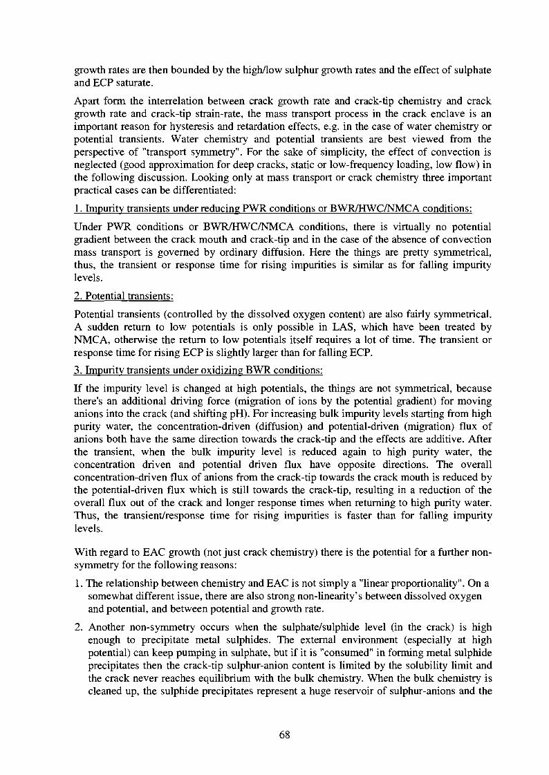
growth rates are then bounded by the high/low sulphur growth rates and the effect of sulphateand ECP saturate.
Apart form the interrelation between crack growth rate and crack-tip chemistry and crackgrowth rate and crack-tip strain-rate, the mass transport process in the crack enclave is animportant reason for hysteresis and retardation effects, e.g. in the case of water chemistry orpotential transients. Water chemistry and potential transients are best viewed from theperspective of "transport symmetry". For the sake of simplicity, the effect of convection isneglected (good approximation for deep cracks, static or low-frequency loading, low flow) inthe following discussion. Looking only at mass transport or crack chemistry three importantpractical cases can be differentiated:
1. Impurity transients under reducing PWR conditions or BWR/HWC/NMCA conditions:
Under PWR conditions or BWR/HWC/NMCA conditions, there is virtually no potentialgradient between the crack mouth and crack-tip and in the case of the absence of convectionmass transport is governed by ordinary diffusion. Here the things are pretty symmetrical,thus, the transient or response time for rising impurities is similar as for falling impuritylevels.
2. Potential transients:
Potential transients (controlled by the dissolved oxygen content) are also fairly symmetrical.A sudden return to low potentials is only possible in LAS, which have been treated byNMCA, otherwise the return to low potentials itself requires a lot of time. The transient orresponse time for rising ECP is slightly larger than for falling ECP.
3. Impurity transients under oxidizing BWR conditions:
If the impurity level is changed at high potentials, the things are not symmetrical, becausethere's an additional driving force (migration of ions by the potential gradient) for movinganions into the crack (and shifting pH). For increasing bulk impurity levels starting from highpurity water, the concentration-driven (diffusion) and potential-driven (migration) flux ofanions both have the same direction towards the crack-tip and the effects are additive. Afterthe transient, when the bulk impurity level is reduced again to high purity water, theconcentration driven and potential driven flux have opposite directions. The overallconcentration-driven flux of anions from the crack-tip towards the crack mouth is reduced bythe potential-driven flux which is still towards the crack-tip, resulting in a reduction of theoverall flux out of the crack and longer response times when returning to high purity water.Thus, the transient/response time for rising impurities is faster than for falling impuritylevels.
With regard to EAC growth (not just crack chemistry) there is the potential for a further non-symmetry for the following reasons:
1. The relationship between chemistry and EAC is not simply a "linear proportionality". On asomewhat different issue, there are also strong non-linearity's between dissolved oxygenand potential, and between potential and growth rate.
2. Another non-symmetry occurs when the sulphate/sulphide level (in the crack) is highenough to precipitate metal sulphides. The external environment (especially at highpotential) can keep pumping in sulphate, but if it is "consumed" in forming metal sulphideprecipitates then the crack-tip sulphur-anion content is limited by the solubility limit andthe crack never reaches equilibrium with the bulk chemistry. When the bulk chemistry iscleaned up, the sulphide precipitates represent a huge reservoir of sulphur-anions and the
68
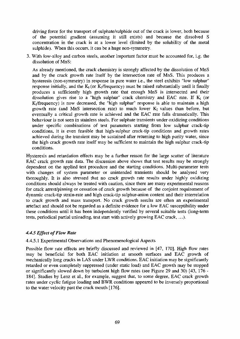
driving force for the transport of sulphate/sulphide out of the crack is lower, both becauseof the potential gradient (assuming it still exists) and because the dissolved Sconcentration in the crack is at a lower level (limited by the solubility of the metalsulphide). When this occurs, it can be a huge non-symmetry.
3. With low-alloy and carbon steels, another important factor must be accounted for, i.g. thedissolution of MnS:
As already mentioned, the crack chemistry is strongly affected by the dissolution of MnSand by the crack growth rate itself by the intersection rate of MnS. This produces ahysteresis (non-symmetry) in response in pure water i.e., the steel exhibits "low sulphur"response initially, and the Kj (or Kj/frequency) must be raised substantially until it finallyproduces a sufficiently high growth rate that enough MnS is intersected and theirdissolution gives rise to a "high sulphur" crack chemistry and EAC rate. If Ki (orKi/frequency) is now decreased, the "high sulphur" response is able to maintain a highgrowth rate (and MnS intersection rate) to much lower Ki values than before, buteventually a critical growth rate is achieved and the EAC rate falls dramatically. Thisbehaviour is not seen in stainless steels. For sulphate transients under oxidizing conditionsunder specific combinations of test parameters starting from low sulphur crack-tipconditions, it is even feasible that high-sulphur crack-tip conditions and growth ratesachieved during the transient may be sustained after returning to high purity water, sincethe high crack growth rate itself may be sufficient to maintain the high sulphur crack-tipconditions.
Hysteresis and retardation effects may be a further reason for the large scatter of literatureEAC crack growth rate data. The discussion above shows that test results may be stronglydependent on the applied test procedure and the starting conditions. Multi-parameter testswith changes of system parameter or unintended transients should be analysed verythoroughly. It is also stressed that no crack growth rate results under highly oxidizingconditions should always be treated with caution, since there are many experimental reasonsfor crack arrest/pinning or cessation of crack growth because of the conjoint requirement ofdynamic crack-tip strain-rate and high crack-tip sulphur-anion content and their interrelationto crack growth and mass transport. No crack growth results are often an experimentalartefact and should not be regarded as a definite evidence for a low EAC susceptibility underthese conditions until it has been independently verified by several suitable tests (long-termtests, periodical partial unloading, test start with actively growing EAC crack, ...).
4.4.5 Effect of Flow Rate
4.4.5.1 Experimental Observations and Phenomenological Aspects
Possible flow rate effects are briefly discussed and reviewed in [47, 170]. High flow ratesmay be beneficial for both EAC initiation at smooth surfaces and EAC growth ofmechanically long cracks in LAS under LWR conditions. EAC initiation may be significantlyretarded or even completely suppressed (under static load) and EAC growth may be stoppedor significantly slowed down by turbulent high flow rates (see Figure 29 and 30) [43, 176 -184]. Studies by Lenz et al., for example, suggest that, to some degree, EAC crack growthrates under cyclic fatigue loading and BWR conditions appeared to be inversely proportionalto the water velocity past the crack mouth [176].
69
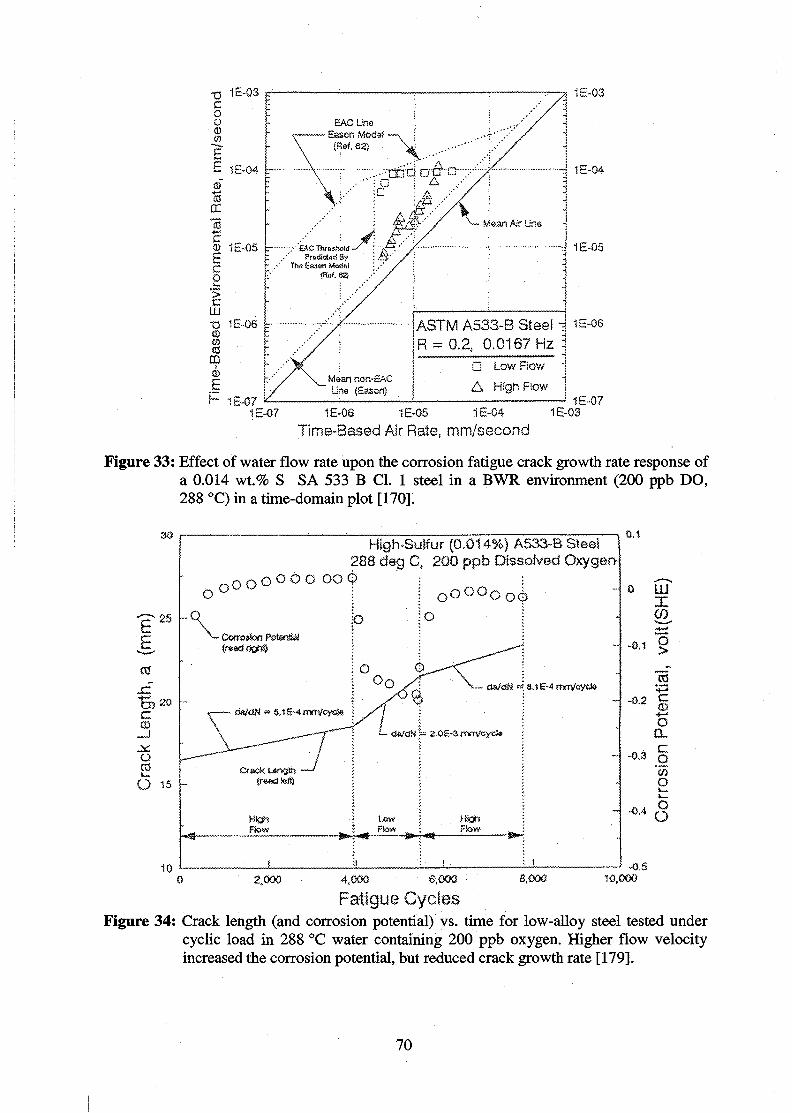
1E-03
Mean non-SACUne (Sasen)
ASTM A533-B Steel i= 0.2, 0.0167 Hz ]
Low Flow
High Ftow
1E-04
1E-05
1E-08 1E-05 1E-04
Time-Based Air Rate, mm/second1E-03
1E-07
Figure 33: Effect of water flow rate upon the corrosion fatigue crack growth rate response ofa 0.014 wt.% S SA 533 B Cl. 1 steel in a BWR environment (200 ppb DO,288 °C) in a time-domain plot [170].
High-Sulfur (0.014%) A533-B Steel !288 deg C, 200 ppfa Dissolved Oxygen-
O O Q Q G O GO4>
O.t
xCO.
-o.t %
-0.2 g
oa.
o
- I2,000 8,000 10,0004.0CX) 6,000
Fatigue CyclesFigure 34: Crack length (and corrosion potential) vs. time for low-alloy steel tested under
cyclic load in 288 °C water containing 200 ppb oxygen. Higher flow velocityincreased the corrosion potential, but reduced crack growth rate [179].
70
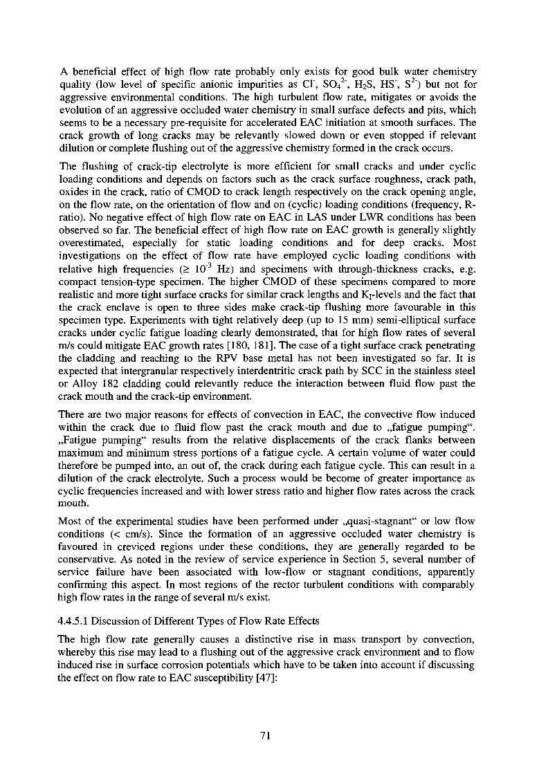
A beneficial effect of high flow rate probably only exists for good bulk water chemistryquality (low level of specific anionic impurities as Cl\ SO42", H2S, HS\ S2") but not foraggressive environmental conditions. The high turbulent flow rate, mitigates or avoids theevolution of an aggressive occluded water chemistry in small surface defects and pits, whichseems to be a necessary pre-requisite for accelerated EAC initiation at smooth surfaces. Thecrack growth of long cracks may be relevantly slowed down or even stopped if relevantdilution or complete flushing out of the aggressive chemistry formed in the crack occurs.
The flushing of crack-tip electrolyte is more efficient for small cracks and under cyclicloading conditions and depends on factors such as the crack surface roughness, crack path,oxides in the crack, ratio of CMOD to crack length respectively on the crack opening angle,on the flow rate, on the orientation of flow and on (cyclic) loading conditions (frequency, R-ratio). No negative effect of high flow rate on EAC in LAS under LWR conditions has beenobserved so far. The beneficial effect of high flow rate on EAC growth is generally slightlyoverestimated, especially for static loading conditions and for deep cracks. Mostinvestigations on the effect of flow rate have employed cyclic loading conditions withrelative high frequencies (> 10~3 Hz) and specimens with through-thickness cracks, e.g.compact tension-type specimen. The higher CMOD of these specimens compared to morerealistic and more tight surface cracks for similar crack lengths and Ki-levels and the fact thatthe crack enclave is open to three sides make crack-tip flushing more favourable in thisspecimen type. Experiments with tight relatively deep (up to 15 mm) semi-elliptical surfacecracks under cyclic fatigue loading clearly demonstrated, that for high flow rates of severalm/s could mitigate EAC growth rates [180, 181]. The case of a tight surface crack penetratingthe cladding and reaching to the RPV base metal has not been investigated so far. It isexpected that intergranular respectively interdentritic crack path by SCC in the stainless steelor Alloy 182 cladding could relevantly reduce the interaction between fluid flow past thecrack mouth and the crack-tip environment.
There are two major reasons for effects of convection in EAC, the convective flow inducedwithin the crack due to fluid flow past the crack mouth and due to ,,fatigue pumping".,,Fatigue pumping" results from the relative displacements of the crack flanks betweenmaximum and minimum stress portions of a fatigue cycle. A certain volume of water couldtherefore be pumped into, an out of, the crack during each fatigue cycle. This can result in adilution of the crack electrolyte. Such a process would be become of greater importance ascyclic frequencies increased and with lower stress ratio and higher flow rates across the crackmouth.
Most of the experimental studies have been performed under ,,quasi-stagnant" or low flowconditions (< cm/s). Since the formation of an aggressive occluded water chemistry isfavoured in creviced regions under these conditions, they are generally regarded to beconservative. As noted in the review of service experience in Section 5, several number ofservice failure have been associated with low-flow or stagnant conditions, apparentlyconfirming this aspect. In most regions of the rector turbulent conditions with comparablyhigh flow rates in the range of several m/s exist.
4.4.5.1 Discussion of Different Types of Flow Rate Effects
The high flow rate generally causes a distinctive rise in mass transport by convection,whereby this rise may lead to a flushing out of the aggressive crack environment and to flowinduced rise in surface corrosion potentials which have to be taken into account if discussingthe effect on flow rate to EAC susceptibility [47]:
71
Type A: Crack-tip flushing
Depending on both length, geometry of crack and level of flow rate, there is an opportunityfor properly oriented flow to dilute or completely flush out of the aggressive chemistryformed in the crack. This is relevant to PWR conditions, where dissolution of MnS-inclusionsin the crack can produce an aggressive chemistry and accelerate crack growth rates. It hasbeen demonstrated by many independent tests that crack-tip flushing by high flow rates mayrelevantly slow down EAC crack growth rates in LAS under these conditions [181, 182, 185,186].
Type B: Crack-tip flushing with increase of crack-tip corrosion potential
In oxidizing BWR environments, crack-tip flushing is related to a large increase in corrosionpotential at the crack-tip from the presence by convection of high oxidant levels. Experimentsby Lenz et al.[176 ] and Katada [179] have demonstrated, that even under BWR conditionshigh flow rates may mitigate EAC growth rates. In experiments in oxygenated high-temperature water with crack-tip microsampling with very high sampling rates, whereflushing of the crack-tip electrolyte occurs, EAC growth rates have been relevantly sloweddown, compared to low sampling rates [46, 86]. As noted in Section 4 EAC growth in LAS isprimarily governed by the crack-tip pH and activity of specific anionic impurities but not bythe crack-tip corrosion potential.
Type C: Flow induced increase rise in surface corrosion potential
At low bulk oxygen concentrations (10 - 100 ppb), high flow rates can produce a significantincrease in the external (crack mouth) corrosion potential (up to 400 mV). At low DO andlow flow conditions, oxygen reduction and ECP is controlled by the diffusion of oxygenthrough the diffusion layer to the steel surface. The DO concentration at the steel surface islower than in the bulk environment and results in a low ECP. An increased flow will reducethe thickness of the stagnant boundary layer and increase the DO concentration and ECP atsteel surface. At very high flow rates oxygen reduction kinetics is controlled by the reductionreaction itself (activation polarisation) but not by mass transport. The oxygen concentration atsteel surface and in the bulk environment are identical. Under these conditions, ECP is ca.independent on flow rate and has reached its highest value for a given DO.
The higher ECP at crack mouth would result in an increase in potential gradient betweencrack mouth and deaerated crack-tip, which is at rest, and in the potential gradient drivenmigration of specific dangerous anions towards the crack-tip. Because corrosion potential andSCC growth rates are strongly correlated, there has been a sensible concern that this willproduce substantially increased SCC susceptibility and crack growth rates.
While the effect of flow-induced elevation of corrosion potential has traditionally beenviewed as promoting SCC, it has been recently proposed by Andresen that the deleteriouseffect of flow rate can be ignored, and the corrosion potential relevant to EAC advance is the,,low flow" potential (see Figure 35). This view is based on recognition that the effect ofcorrosion potential can be understood in terms of the role of the potential-driven ionmigration in mass transport (i.e. in crevice differential aeration cell). The kinetics of masstransport is such that convection completely overwhelms (by many orders of magnitude) thecontributions of ordinary concentration gradient driven diffusion and potential gradientdriven ion migration. The presence of high convection prevents the formation of an occludedchemistry where convection exists, thus eliminating any relevant concentration and potentialgradient (concentration or flow-induced) in this region (see Figure 35). Thus, whereconvection is present, there is no relevant diffusion and migration. Occluded chemistry canonly form near the point of ,,zero convection" in the crack, and the relevant potential is
72

associated with the low flow conditions at this location. This location referred to as the,,electrochemical crack mouth". Between the geometrical crack mouth and theelectrochemical crack mouth, any effect of potential gradient is overwhelmed by convection.Thus, while the corrosion potential at the free surface may be greatly elevated under highflow rate conditions, the flow merely acts to shift the electrochemical crack mouth into thecrack. There are some few tests under conditions, where corrosion potential at externalsurface has been shifted by high flow rate [179]. The EAC growth rates have been sloweddown at high flow rates under these conditions. The slow down of crack growth might be aneffect of crack-tip flushing. Further critical experiments at low DO levels with low and highflow rate with long cracks where flushing of crack-tip environment can be excluded would benecessary to verify the hypothesis of Andresen.
Hgn fiow rate field
4 A mX ) ' >.
r c* ?m r*\
, |f- c ••s^jir m » ' ! iv ' ;
D, concentration atcenter?r.e o! crack
Figure 35: Schematic of the electrochemical crack mouth, which is defined as the location inthe crack enclave where convective flow becomes small. Since convectiondominates diffusion and migration, the electrochemical crack mouth is defined asthe location where the contribution of the potential gradient can stronglyinfluence mass transport and the crack chemistry. At locations toward thegeometric crack mouth, the effect of any potential gradient is overwhelmed byconvection. Thus, while the corrosion potential at the free surface may be greatlyelevated under high flow rate conditions, the flow rate merely acts to shift theelectrochemical crack mouth into the crack [47].
High flow rates may be beneficial for both EAC initiation and growth. High flow rates maysignificantly retard EAC initiation but not completely prevent it. High flow rates mayrelevantly slow down crack growth under cyclic fatigue loading conditions and/or underconditions where flushing out of the aggressive crack environment can occur. For staticloading conditions and deep cracks, the beneficial effect of high flow past the crack mouth isgenerally overestimated and only a minor effect is expected here compared to low flow andquasi-stagnant conditions. The only case, where EAC might be significantly accelerated byhigh flow rates, is the situation in high-temperature water with low DO and high flow, whereECP is significantly shifted on the external surface, but the flow does not enter the crack, sothat an occluded chemistry can form, a situation which seems not to be very realistically.
73
5. LWR Operating Experience and EAC Cracking IncidentsIt is obvious from the accumulated experience of operating PWR and BWR that EAC of low-alloy pressure vessel and piping steels is not a major problem in the sense that it is clearly notwidespread in occurrence. Nevertheless, rare instances of EAC in LAS have occurred, moreoften in pipelines than in pressure vessels and very rarely in reactor pressure (RPV) vesselsthemselves [16, 19, 89]. One reason for this is that low-alloy RPV steel does not come intocontact with the liquid phase primary coolant since in common Western LWR designs mostparts of the RPV are normally protected by a duplex or stabilised austenitic stainless steelweld overlay cladding providing a high stability against EAC and thermal fatigue.
Compared to fossil power plants, where corrosion fatigue continues to be the damagemechanism responsible for the largest percentage of availability loss, the world-wideaccumulated operating experience and performance of low-alloy primary pressure-boundarycomponents in LWR has been excellent. This is attributable to a relevant part to the qualityand care with which the nuclear systems have been designed, built, maintained, and operated,in addition to the large conservatism introduced at the design stage, especially with respect tothe known or anticipated mechanism of failures including fatigue. Thus the initial chance ofoccurrence was reduced through the design basis and, when indications were found orsuspected at critical locations in some plants, augmented inspections and operationalprocedures were instituted to further reduce the chance of fatigue failures in service.
The high standards of safety and reliability on pressure-boundary components in NPP requirethat even very low probability failures must be understood to prevent recurrences by adequatecountermeasures. Therefore it is essential to define the conditions under whichenvironmentally-assisted cracking can occur in high-temperature water and to quantifymargins between normal operating and upset conditions which can cause EAC.
5.1 EAC Cracking Incidents in LWR
Cracking incidents have occurred in BWR and less distinct in PWR. Carbon and low-alloysteel components [14, 16, 19, 26, 32, 89] being involved are pressure vessels [187], steamgenerators [188, 189], piping [190 - 194], deaerators [195 - 197], and steam turbine discs[198 -200]. Just in the latter situation intergranular cracking of prior austenitic grainboundaries in bainitic NiCrMo and CrMo steels (HAEAC) has been observed. In all othercases cracking has been predominantly transgranular in nature where carbon or low-alloysteels covered by the designations of SA 333Gr6, SA 106, SA 302GrB, SA 533 B, or SA 508(and other national equivalents) have been involved. The following discussion is focused onlow-alloy LWR primary pressure-boundary components.
5.1.1 Common Features of EAC Cracking Incidents
Most EAC cracking incidents have been carefully analysed and documented in literature.Notwithstanding that even similar components can significantly differ in design details, indesign and material concepts, in manufacturing and fabrication process and in operation-related features and operation history, common features and similarities of these crackingincidents could be derived. These EAC incidents have been often associated with, andexacerbated by, various combinations of:
- severe dynamic straining, due to thermal stratification/stripping (e.g. during hot-stand-by atlow feedwater flow rate) or due to thermal and pressurisation cycles (e.g. plant-start-up/shut-down, hot stand-by,...).
74
- an oxidizing environment due to e.g. oxygen (BWR pipe lines carrying stagnant steam ornon-degassed condensate during normal operating, ...) or Cu2+-cations (leakage from brasscondensers,...), sometimes in conjunction with unspecified anionic impurities (Chloride,..).
- high local stress around or above the HT yield stress or high secondary or residual stressdue to, for instance, localised post-weld treatment, fit-up deformation, local stress raisers,geometrical welding defects due to misalignment, excessive weld penetration (leading toroot notches and lack of fusion or incipient cracking in the root region).
Instances of EAC have particularly occurred in BWR service, most often in LAS piping, and,very rarely in the RPV itself. EAC damage was usually detected by non-destructiveexamination and seldom led to through-wall penetrations with leakage [19, 32]. In many ofthe reported incidents, EAC in LAS has occurred as a result of substantial departures fromeither design intentions or normal operation practice, which are identifiable and can betherefore avoided [16]. Oxidising agents, usually oxygen, and severe dynamic straining werealways involved [16, 32]. These cases could be attributed either to SICC or low-cyclecorrosion fatigue. Several incidents were related to unanticipated sources, frequency, and/orseverity of thermal stress cycles in critical locations, thus indicating design inadequacies [89].In many cases fabrication or design deficiencies often favoured local plastification (e.g.welding defects) and dynamic straining (e.g. thermal sleeve with old slip fit design, seeSection 5.1.2)) and sometimes resulted in an increased stress intensity (residual stress,welding hot cracks of the cladding) or increased EAC susceptibility of the material (e.g.excessive hardness of LAS weld HAZ, increased IGSCC susceptibility of SS cladding due toinsufficient delta ferrite, martensite formation or extensive cold work due to grinding, ...)[16, 19, 32, 89]. By an improved design of the components or fabrication procedure andquality control during the fabrication process, reoccurrence of these cases could be avoided orsignificantly reduced [16, 19, 32, 89]. In some cases water quality outside current EPRI waterchemistry guidelines (high level of aggressive impurities) has been a further contributingfactor [16].
Cracks often initiated from geometric discontinuities (which result in local stressconcentration and favour the formation of an aggressive, occluded water chemistry) and/or inregions, where the formation of an aggressive environment were favoured (stagnant flow,crevice,...). EAC cracks were mainly initiated from corrosion pits and/or at MnS-inclusions,which intersected the steel surface but rarely if ever from pre-existing large cracks. Ingeneral, crack initiation has been more affected by the high frequency, high-cycle fatigue dueto local thermal stratification or thermal stripping action limited to near surface regions. Thecrack propagation was often dominated by the low-cycle fatigue from slower and lessfrequent transients due to global thermal stratification or operational power transients.
A complete root cause evaluation has not always been performed in all cracking incidents.Therefore, identification of cracking mode respectively the separation of the relativecontributions of EAC (SCC or SICC/CF) or pure mechanical fatigue to the total crackadvance has not always been completely clear. Minor contributions to crack propagation dueto SCC can therefore not be completely ruled out for many cracking incidents, but cases withmajor or relevant contribution of SCC to the total crack advance in properly manufacturedand heat-treated low-alloy primary pressure-boundary components are not known to theauthor. In contrast, certain cases indicate excellent SCC resistance of the base metal understationary power operation conditions, since no corrosion damage in the form of cracks hasoccurred either as a result of extensive surface contact with the operating environment (e.g.for unclad reactor heads or nozzle bore radii) which exhibited extensive contact with the
75

operating environment, or at the tips of cracks ending through the cladding in the low-alloybase metal [187].
Some typical aspects for corrosion-assisted crack advance in low-alloy pressure-boundarycomponents in the primary coolant circuit of BWR will be worked-out in more detail on thebasis of two ,,classical" types of cracking incidents.
5.1.2 EAC of BWR RPV Feedwater Nozzles
EAC has been observed in some RPV feedwater nozzles in BWR [20, 187]. Cracking hasbeen located in the bore and blend radius regions of the SA 508 nozzle (Figure 36) claddedby 308 (non-sensitised) duplex stainless steel. The corresponding thermal sleeve designallowed a leakage flow of cold feedwater in the annulus between the nozzle and the sleeve.
VESSEL WALL
REACTOROGWWCGMEKFLOW
SUP FITJOINT
THERMAL FLOWREGIONOF HfGHFREQUENCYTHERMALCYCLING ANDCRACK1NQ
SPARGER
Figure 36: Cross section of BWR feedwater nozzle with cracking location [20, 187].
As a hypothesis, the cracking was due to a sequence of high cycle fatigue and EAC under lowcycle conditions:
-A high frequency thermal fatigue mechanism (without relevant environmental contribution)initiated cracks in the stainless steel cladding, which subsequently propagated through thelow-alloy steel. This mechanism [20, 187] was attributed to turbulent mixing of the coldleakage flow (220 °C), past the slip fit joint of the safe end, and the hot downcomer flow(280 °C). The mixing fluid impinges on the nozzle wall, causing thermal cycling atfrequencies in the range of 0.01 to 1 Hz. The thermal stress amplitude from this particularsource degrades to zero when the crack propagates to an approximate 6 mm depth. An
76
alternate thermal sleeve designs and removal of cladding by grinding, which minimise thehigh frequency thermal stresses, has been revealed as an adequate countermeasure.
- Further propagation of this crack in the LAS has been assigned to low frequency thermaland pressurization cycles associated with e.g., start-up/shut-down cycles, scrams, turbinerolls, etc. The cracking mechanism could be assigned to SICC or low-cycle CF with relevantenvironmental acceleration of crack growth. SCC under static load during steady-statepower operation seemed not to relevantly contribute to crack advance in this case. Thisassumption is supported by the better correlation between the extent of cracking and thenumber of start-up/shut-down cycles than with the total operating period [20, 187].
5.1.3 SICC of Thin-Walled Pipings in German BWR
Relatively high strength fine-grained structural steels (WB 35) have been widely used inGermany, e.g. for the construction of pressure vessels and piping in BWR systems and for thefabrication of feedwater tanks and heat exchanger in the secondary circuit of PWR whichenabled to manufacture relative thin-walled components. Cracking incidents have beenoccasionally observed in feedwater tanks of PWR but more often in thin-walled piping ofBWR with stagnant steam or stagnant high-temperature water. Several of these cases werereviewed in [18, 32, 38, 201 -203] and possible mitigation remedial actions are discussed in[193, 204 - 207]. In all these cases oxidizing conditions and local dynamic straining wereinvolved. The PWR cases cited above involved feedwater under operating conditions, forwhich the normally low contents of oxygen cannot be assumed.
The piping cracking incidents could be attributed to SICC (strain-rate-sensitive SCC) and insome few cases to corrosion fatigue at very low cyclic frequencies. The crack growth wasrather intermittent and occurred during special operating conditions (start-up/shut-down, hot-stand-by at low feedwater rates with thermal stratification). Typical chemical and cyclicstrain transients in LWR pressure-boundary components are specified in Table 5. Thespecified conditions fit excellent to the SICC susceptibility conditions observed in SSRT tests(see Figure 17 in Section 3.). There were no indications for relevant SCC crack growth understatic loading during steady state power operation. The cracks often initiated in regions ofincreased local stress above the design level (for example at welding defects, pipe bends inconjunction with inadequate pipe support or restraints) or in horizontal pipe sections wherethermal stratification could occur. The fact that frequently cracking occurred in lines withstagnant steam or non-degassed condensate, but not in comparable lines carrying flowingsteam, is a indication that oxygen concentration/corrosion potential are a crucial parametersin respect to the occurrence of SICC, since such conditions are known to encourage theformation of a condensate rich in dissolved oxygen.
Many early SICC field incidents involved stagnant conditions, where the real conductivity ofthe water within the porous oxide/hydroxide layer immediately adjacent to the surface of theaffected component might be expected to be much higher. Significantly, cracking hasoccurred in recent years in Germany in BWR feedwater lines, although the purity of the bulkmedium was exceptionally high [209]. Geometrically, however, it was clearly associated withareas in the lower part of the horizontal piping where corrosion products (primarily rust) hadformed from water residues during prior shut-down. Thus it is possible that a local, "micro-environment" of much higher conductivity had still existed during plant start-up, i.e. at thetime when significant, dynamic straining at welds in the piping also occurred.
77

om portent "ration O2 (ppb) Temp. CC Ae, % «, 1/s
PWRSG FW NozzleBWRPV FW NozzleBWR FW PipingBWR. FW PipingBWR FW PipingBWR FW PipingBWR FW PipingBWR FW Piping
StartupStartupStartupStartupTurbine RollHot Stand-byCool downStratification
5
20/20020/20020/200< 200< 200< 2 0200
230/RT218/38216/38288/38288/80
. 288/90288/RT250/50
0.2-00.2-00.2 00.08?0.4
0.260.2
0.2 0
.0
.4
.5
0.1
*}
10—1 0 -10~5 10—4-8xlO"8
3 6xlO~5
4xl0"6
> 6xlO™6
10-e-10"5
Table 5: Typical chemical and cyclic strain transients in LWR pressure-boundary-components [208].
5.2 Operating Experience vs. Laboratory Background Knowledge
The results of root cause analysis of different cracking incidents fit well to the accumulatedexperimental and mechanistical background knowledge on the EAC and pitting behaviour inthe system LAS/high-temperature water (see Section 3.2, Table 3 and 4). The operationexperience confirms the high SCC resistance of quenched and tempered LAS under steady-state power operation and static loading conditions. Both operating experience and lab dataclearly reveal that slow, positive (tensile) dynamic straining with associated plastic yieldingand sufficiently oxidising conditions are essential for EAC initiation and subsequent growthin high-temperature water of high or moderate purity. Since primary design stress aregenerally limited to values below the elastic limit, (local) plastification at defect-free surfacescan only occur under special operation conditions with high secondary stresses (thermalstresses) or in regions of increased local stress (notches, residual stress,...). EAC cracks ofteninitiated from corrosion pits or MnS-inclusions which intersected the steel surface. Pitting ofLAS is strongly favoured under oxidising conditions (high oxygen concentration) especiallyat low and intermediate temperatures and by slow dynamic straining. Quasi-stagnant or lowflow conditions are promoting the formation of an aggressive occluded water chemistry at thepit ground and therefore strongly promoting EAC initiation.
So far we could not find any major discrepancy between operating experience and trends inlaboratory data. The following two major apparent disparities have been sometimesmentioned in literature:
• EAC is much easier to induce in laboratory specimens tested in autoclaves under simulatedLWR conditions, particularly in steels with elevated concentrations of sulphur, than inoperating components under comparable conditions.
• There is no evidence for a relevant SCC susceptibility of LAS base metal under stationarypower operation condition. Here there seemed to exist an enormous discrepancy betweenoperating experience and some very high SCC crack growth rate laboratory data understatic loading under nominal BWR conditions reported in literature. This discrepancy wasexplained by crack initiation problems (low probability, extremely long incubation periods)under BWR power operation conditions (with high flow rate and high purity of the coolant)and there was a concern that, if crack initiation should occur, then high crack growth ratesrelative to operational time scales or inspection intervals might be observed.
78
5.2.1 Reasons for Higher EAC Cracking Frequency in Laboratory Tests
There are several reasons, why EAC is more frequently observed in lab tests than in operatingcomponents under nominally comparable conditions:
- For the occurrence of EAC initiation (and subsequent growth), several parameters such asthe ECP, strain-rate, strain and temperature have to simultaneously exceed certain thresholdvalues during a sufficiently long period (see Section 3.2). If one threshold condition is notsatisfied, no relevant effect of the environment on fatigue initiation and growth is observed.The probability of EAC initiation is then extremely low and even an initially growing EACcrack will generally arrest. The probability that all these factors are simultaneouslyachieved is relatively low and for many component locations/operation conditions one orseveral of these factors are missing. A high EAC risk is therefore restricted to some fewcritical component locations and/or special operation conditions. Even if these conjointthreshold conditions are simultaneously fulfilled, crack initiation process may require arelevant time period and crack growth rates can be very slow.
- Furthermore, a high flow rate representative for most RPV locations may completelysuppress or at least retard crack initiation by suppressing the evolution of an aggressiveoccluded water chemistry in pits or small surface defects by flushing the pit or defectenvironment. Even crack growth of deep cracks may be completely suppressed orrelevantly slowed down if flushing of crack-tip environment occurs.
Most laboratory experiments were performed under low flow or quasi-stagnant conditions,whereas most locations are subjected to turbulent high flow rate conditions.
- Most laboratory experiments start with a sharp and relatively deep fatigue pre-crack that is,,ready" to propagate; most structural components do apparently not (see Section 5.1). Inthe absence of pre-existing defects or cracks, EAC cracks need to be initiated at the freesurface before propagation can occur, and this process may consume a large part of the lifetime or many fatigue cycles.EAC initiation at fatigue pre-cracked specimens is facilitated with respect to defect freesurfaces for the following reasons:Since primary design stresses are limited below the yield strength, plasticity at defect-freesurfaces are restricted to regions of increased local stress (e.g. notches, weld defects andresidual stress) or to special operation conditions with high secondary thermal stresses. Thepre-requisite of plasticity is always given in pre-cracked specimens. In pre-crackedspecimens, a large volume of MnS-inclusions is intersected by the pre-crack crack plane.The dissolution of these MnS-inclusion and the creviced geometry of the pre-crack (withhigh aspect ratio) favours the formation of an occluded aggressive EAC promoting crack-tip environment. At smooth defect-free surfaces, the evolution of an occluded aggressiveenvironment in small corrosion pits and therefore the initiation and subsequent EAC growthmay be completely suppressed by flushing of the environment at the pit ground. Hushing ofcrack-tip environment in deep surface cracks is more difficult.
- In western LWR most parts of the RPV are protected by a duplex or stabilised austeniticstainless weld overly cladding with a high stability against EAC. EAC in the RPV requirescracking of this cladding and direct access of the environment to the crack enclave.
79

5.2.2 Reasons for High SCC Cracking Susceptibility in Some Lab Tests
Reasons for the large scatter and for the very high SCC crack growth susceptibilitysometimes observed under "nominal" BWR water chemistry conditions have been discussedin Section 3 and 4. Many tests revealing those high SCC crack growth rates plotted inFigure 20 have been performed under a combination of both gross yielding of the remainingspecimen ligament which is not relevant to the thick-walled RPV structure and aggressivewater chemistry conditions which are not representative for current BWR operation. Anotherimportant reason for high crack growth rates have been loading conditions significantlydifferent from static loading, e.g. slow rising displacement tests or tests with periodical partialunloading with very short constant load periods in-between, where relevant dynamic crack-tip straining by external loading occurs. In many older investigations, system parametershaving a strong influence on crack growth were neither sufficiently controlled and monitorednor documented. Thus, the transferability and relevance of these data to pressure-boundarycomponents and to BWR power operation conditions cannot be evaluated. In those caseswhere enough information on testing characteristics were available to the author, either no orvery slow SCC crack growth rates were observed under simulated BWR conditions, orplausible reasons for the deviations form this behaviour based on the accumulated wellaccepted experimental and theoretical background knowledge for the system underinvestigation, could be given (see Section 3.6.3)
The high SCC cracking susceptibility observed in older tests could not be reproduced byrecent reactor site testing [25, 26] and by recent experiments [28, 30, 138] in modern high-temperature loops with water refreshment, on-line crack growth monitoring anddocumentation of all relevant test parameter. From these investigations it is now more andmore apparent that the ,,low sulphur line" can be regarded as an upper bound for possibleSCC crack growth rates under current BWR operating practice. Relevant additional dynamicloading is necessary to maintain low sulphur crack growth rates if water chemistry conditionswere maintained within current BWR operation practice to some extent. Otherwise crackarrest occurs under purely static loading.
The high crack growth rates down to small stress intensity factors are in clear contradiction tothe world-wide accumulated RPV operation experience. Clearly, if there would be a practicalproblem of that magnitude occurring generally under conditions relevant to power operation,then no low-alloy steel vessel used in high performance steam production plant, nuclear ornon-nuclear, and especially those vessels, where EAC cracking has been observed throughthe cladding down to the unaffected base metal, could survive, which is manifestly not thecase.
5.2.3 Summary
LAS pressure-boundary components in nuclear RPVs had an excellent service record.Nevertheless, rare instances of environmentally-assisted cracking have occurred, more oftenin pipework than in pressure vessel and very rarely in reactor pressure vessels themselves.Components in BWR have been involved much more than in PWR. Oxidising agents, usuallyoxygen itself, and relevant dynamic straining were always involved in these crackingincidents. They could be attributed to SICC or low-cycle CF, but hardly if ever to SCC.Incidents in PWR did generally occur under operation conditions, where the presence ofoxidising agents cannot be excluded and/or the concentration of specific impurities didclearly exceed current water chemistry guidelines. Under reducing conditions characteristicfor the primary coolant circuit of PWR under steady-state power operation, the LAS are not
80

susceptible to SCC. Compared to BWR, the susceptibility to SICC and low-cycle CF isdrastically reduced.
As long as water chemistry is maintained within current BWR/NWC operation practice tosome extent, properly manufactured and heat-treated LAS pressure-boundary componentsseem not be susceptible to sustained, fast SCC growth under static load. Therefore, relevantSCC crack growth under transient-free steady-state BWR/NWC power operation appears tobe highly unlikely. In contrast to their high stability against SCC, the LAS show a distinctsusceptibility to SICC/low-cycle CF in oxygenated high-temperature water, even at very lowimpurity levels, if suitable slow dynamic/cyclic loading conditions do occur during operation.
5.3 Possible EAC Prevention Strategies and Mitigation Actions
The common SCC/SICC mitigation strategy is to exclude large pre-existing defects byadequate non-destructive examination and quality assurance measures during and afterfabrication of components before they were put in operation and to avoid during operationthose water chemistry/stress or strain combinations, which could lead to crack initiation. Thisprocedure is applied for primary pressure-boundary components in nuclear power plants. Thecurrent LWR operation practice, EPRI water chemistry guidelines and the applied designcodes are successful in avoiding most critical conditions for EAC initiation. The currentfatigue design rules have been successful in preventing cracks in carbon and low-alloy steeland are very conservative and adequate under most circumstances. As revealed by theoperation experience, it is very likely that SICC, or very low-cycle CF behaviour, that coversthe most important gap in the design rules and fatigue usage methodologies. The short-livedplant transients (start-up/shut-down, hot stand-by, turbine trips, with temperature/pressurization cycles, thermal stratification,...) have been identified as periods when SICC ismost likely to occur.
Nevertheless, cracking in operating components may be induced by (unanticipated) transientor faulted operation conditions or may be (and has been) observed by ND-inspection duringservice. Furthermore, ND inspection methods have a limited resolution, sizing probabilityand reliability, therefore reactor safety analysis is primarily based on crack growthevaluations of postulated pre-existing cracks. Therefore reliable data on the SCC/SICC crackpropagation behaviour are necessary and essential for both safety considerations/structuralintegrity assessments and to set-up/adapt ND inspection intervals, especially for safety-relevant primary pressure-boundary components, e.g. the RPV. There is still a lack of reliablequantitative SICC crack growth rate data under short-lived plant transients (start-up/shut-down, hot stand-by, turbine trips, with temperature/pressurization cycles, thermalstratification,...).
For safety-relevant LAS primary pressure-boundary components, only the combination ofavoiding of water chemistry/stress or strain combinations which promote crack initiation withstructural integrity/safety assessments based on fracture control (based on non-destructive-inspection, crack growth evaluations and fracture mechanics analysis) can be guaranteed tobe effective, since crack initiation during service can never be completely ruled out andbecause rates of environmentally-assisted crack growth can be sufficiently high under certaincritical conditions relative to plant operational time scales.The LAS show a distinct susceptibility to SICC in oxygenated, high-temperature water, evenat very low impurity levels, if suitable slow dynamic/cyclic loading conditions occur duringoperation. It is therefore important to systematically identify specific circumstances thatchallenge the conservatism in present design rules and the possible system conditions(operating conditions, critical components) where such conditions can or could occur.
81

5.3.1 Critical Components
Critical components in NPP are for example [32]:
- pipelines carrying nearly stagnant steam or non-degassed condensate during normaloperation (or which are used only intermittently).
- feedwater nozzles and adjacent sections of horizontal piping, if thermal stratification canoccur.
- components, which are likely to undergo significant localised mechanical loading over orabove the design levels (e.g. thin-walled piping and pipe bends in conjunction withinadequate pipe supports or restraints).
5.3.2 Mitigation Actions
Based on the operating experience and laboratory background knowledge different short orlong-term remedial measures have been successfully defined and applied [193, 204 - 207] forexample by changing or optimising of manufacturing, processing, design and operationrelated features. In any sensitive preventing strategy risks from fabrication defects have to beeliminated (ND inspection, QA). Operating conditions and component designs should beoptimised to avoid dynamic straining and highly oxidizing/ stagnant conditions.
In summary SICC/SCC risks can be minimised by (for technical details see [193, 204 - 207]):
- suitable selection of materials e.g. low sulphur steel (< 0.010 wt.% S) with high toughness.
- suitable selection of manufacturing and fabrication practice to avoid welding defects andHAZ with high hardness (< 300 VH by properly performed post-weld heat treatments) andto reduce residual stress (stress relieving).
- an improved design to reduce regions of high local stresses (by increased wall thickness, byinternal flush grinding of joints and optimisation of welding technology)
- avoiding or reducing the number of thermal and pressurisation cycles (thermal-stratificationduring hot stand-by, start-up/shut-down) by optimised operating procedure or an improveddesign of the affected component (thermal sleeve of feedwater nozzle, feedwater sparger)
- avoiding stagnant conditions and reducing oxygen levels by optimised operation practice(for example modification of start-up procedures to reduce dissolved oxygen levels by betterventing of piping, improvement of drainage in horizontal lines,...)
- an adequate water chemistry control (EPRI or VGB guidelines), HWC/NMCA.
82
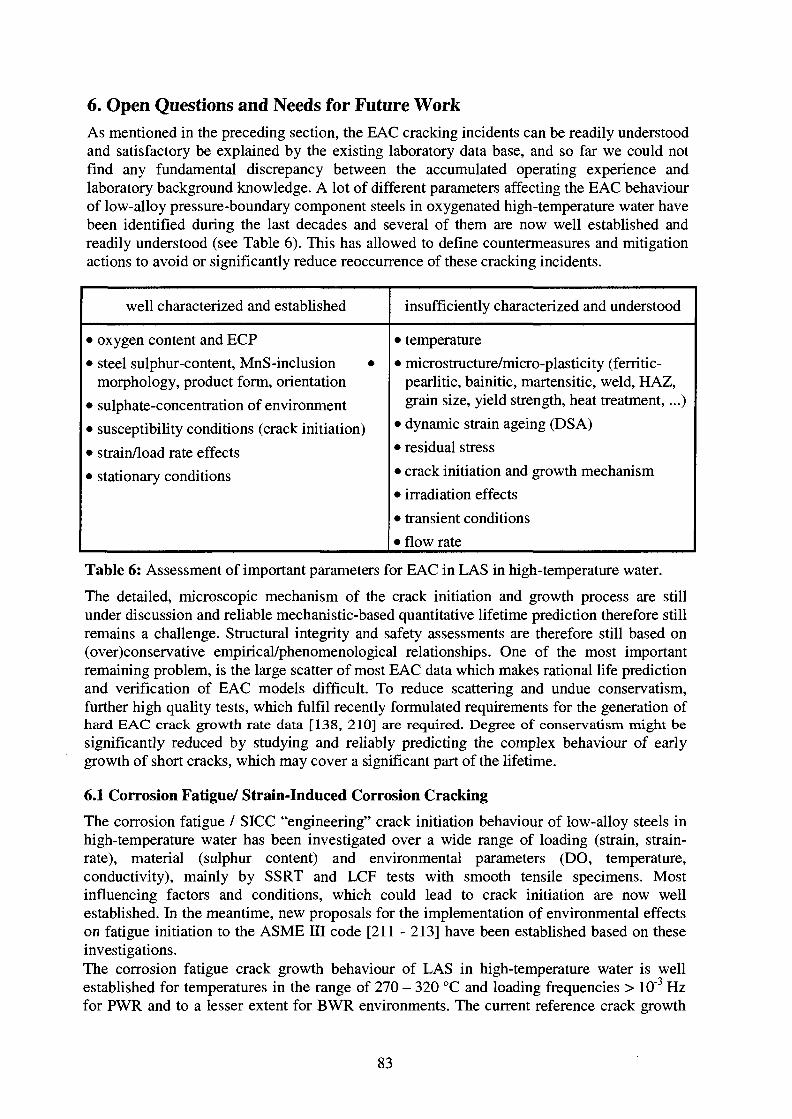
6. Open Questions and Needs for Future WorkAs mentioned in the preceding section, the EAC cracking incidents can be readily understoodand satisfactory be explained by the existing laboratory data base, and so far we could notfind any fundamental discrepancy between the accumulated operating experience andlaboratory background knowledge. A lot of different parameters affecting the EAC behaviourof low-alloy pressure-boundary component steels in oxygenated high-temperature water havebeen identified during the last decades and several of them are now well established andreadily understood (see Table 6). This has allowed to define countermeasures and mitigationactions to avoid or significantly reduce reoccurrence of these cracking incidents.
well characterized and established
• oxygen content and ECP
• steel sulphur-content, MnS-inclusion •morphology, product form, orientation
• sulphate-concentration of environment
• susceptibility conditions (crack initiation)
• strain/load rate effects
• stationary conditions
insufficiently characterized and understood
• temperature
• microstructure/micro-plasticity (ferritic-pearlitic, bainitic, martensitic, weld, HAZ,grain size, yield strength, heat treatment,...)
• dynamic strain ageing (DSA)
• residual stress• crack initiation and growth mechanism
• irradiation effects
• transient conditions
• flow rate
Table 6: Assessment of important parameters for EAC in LAS in high-temperature water.
The detailed, microscopic mechanism of the crack initiation and growth process are stillunder discussion and reliable mechanistic-based quantitative lifetime prediction therefore stillremains a challenge. Structural integrity and safety assessments are therefore still based on(over)conservative empirical/phenomenological relationships. One of the most importantremaining problem, is the large scatter of most EAC data which makes rational life predictionand verification of EAC models difficult. To reduce scattering and undue conservatism,further high quality tests, which fulfil recently formulated requirements for the generation ofhard EAC crack growth rate data [138, 210] are required. Degree of conservatism might besignificantly reduced by studying and reliably predicting the complex behaviour of earlygrowth of short cracks, which may cover a significant part of the lifetime.
6.1 Corrosion Fatigue/ Strain-Induced Corrosion Cracking
The corrosion fatigue / SICC "engineering" crack initiation behaviour of low-alloy steels inhigh-temperature water has been investigated over a wide range of loading (strain, strain-rate), material (sulphur content) and environmental parameters (DO, temperature,conductivity), mainly by SSRT and LCF tests with smooth tensile specimens. Mostinfluencing factors and conditions, which could lead to crack initiation are now wellestablished. In the meantime, new proposals for the implementation of environmental effectson fatigue initiation to the ASME HI code [211 - 213] have been established based on theseinvestigations.The corrosion fatigue crack growth behaviour of LAS in high-temperature water is wellestablished for temperatures in the range of 270 - 320 °C and loading frequencies > 10"3 Hzfor PWR and to a lesser extent for BWR environments. The current reference crack growth
83
rate curves in the ASME BPV Code Section XI Appendix A are based on data obtained priorto 1980. They depend explicitly on AK and R-ratio, but not on other variables that are knownto be important, such as loading frequency. In the meantime, several laboratories haveconducted extensive testing programmes, including a wide variation of controlled variables.Based on this extended database, a proposal for new reference crack growth curves has beenworked-out by Eason et al. [214, 215], taking into account the strong effect of strain-rate/loading frequency. The BWR database for this proposal was relatively small and mainlybased on tests with an ECP of < + 50 ITIVSHE, temperatures around 288 °C and rise times AtR< 1000 s. There is still a relevant lack of experimental data for high ECP, low loadingfrequencies < 10~3 Hz and intermediate temperatures, but also for very high R-ratios > 0.95.This lack of data therefore results in a relevant uncertainty concerning the conservatism andadequacy of the proposed reference curve for these parameter combinations. Implementationof these proposals to the ASME El and XI codes and code upgrading are still underdiscussion. Practical application of these proposals is difficult and complex, since loadingrate (strain-rate, rise time) is an important parameter.
The current fatigue design and evaluation codes (ASME DI and XI) have been quitesuccessful in preventing fatigue cracks and failures in low-alloy steel (LAS) components, andwould therefore seem to be adequate or conservative under most operating circumstances.Despite the good record of current design rules in preventing cracks in carbon and low-alloysteel, a very few, do still occur. Thus identifying specific circumstances that challenge theconservatism in present rules is necessary. On the other hand, there is an obvious desire toeliminate overconservatism especially in the context of plant life extension assessments.Operational experience (Section 5) and laboratory background knowledge (Section 4) bothindicate that the current fatigue design curves/codes and usage methodologies might be non-conservative for certain critical, short-lived, BWR plant transients (start-up/shut-down, hotstand-by, thermal stratification,...) and that SICC, or very low-cycle CF behaviour covers themost important gap in the field of EAC of LAS. The changes of temperature and/or pressure(and of water chemistry) during such transients result in a complex load spectrum. Theresulting loads may be out of phase or even in anti-phase with the temperature. Thetemperature/strain-rate combinations, which are relevant for these transients again draw theattention to possible DSA effects on EAC.
From a safety perspective, there is a relevant lack of quantitative SICC/low-frequency CFcrack growth data under transient LWR plant conditions (i.e. at slow strain-rates/very lowcyclic frequencies (< 10"3 Hz), intermediate temperatures (100 to 300 °C) and high corrosionpotentials (BWR)), where susceptibility to SICC/low-cycle CF is very high and the ASME XIwet reference curve may be significantly exceeded. The effect of specific impurities (Cl\SO42", ...), corrosion pitting and mean stress on SICC initiation, and the possible effects offlow rate and DSA on crack initiation and growth should be further investigated. Because ofpossible DSA effects, both, weld and weld HAZ have to be included in such investigations(see Section 4.1.3). The effects of random loading or overloads (e.g. hydrostatic test) on EACinitiation and growth have not yet been studied. The efficiency of HWC/NMCA onmitigation of SICC/LCF under transient operating conditions should be also clarified.
To evaluate real plant situations and for lifetime prediction flow rate effects and non-isothermal conditions should be further investigated including tests with surface-crackedspecimens (also with cladding). Such tests might help understand some apparent discrepancybetween operating experience and laboratory results and eventually to eliminate someoverconservatism.
84
6.2 Stress Corrosion Cracking
Both, new laboratory investigations and operating experience are showing that relevant SCCcrack growth does not occur under pure static loading, if water chemistry conditions aremaintained within current BWR normal operation practice to some extent. Based on newresults of qualified tests in simulated BWR environment interim disposition lines for SCCcrack growth in low-alloy pressure-boundary component steels for BWR power operationhave been proposed by an international group of experts within the BWR VIP project [25,26]. This work has been recently accepted by the NRC as an interim position [25].
The quantitative data base for these disposition lines is still relatively small. Testing has beenfocused to water chemistry conditions representative for the bulk reactor water / feedwaterunder transient-free steady state BWR/NWC power operation and to material statesrepresentative for RPV/piping base metal. The disposition lines are primarily based onrelatively short-term (typically around 1000 h) laboratory tests with respect to operationaltime scales. Most investigations under simulated BWR conditions were performed understationary conditions in the temperature range of 270 to 290 °C at dissolved oxygen contentsof 200 ppb to 400 ppb at relatively low ECP compared to the recently measured elevated in-pile values of corrosion potential.
There are many aspects of SCC which have not yet been sufficiently investigated (seeTable 6). From a safety perspective and with regard to a reliable engineeringjudgement/assessment of the possible threat of SCC on the long-term structural integrity ofthe RPV and of other safety-related low-alloy steel pressure-boundary components, thefollowing aspects should be further investigated to close the most important gaps:
- Long-term SCC cracking behaviour:
The disposition lines should be verified by some few long-term (> 1 a) SCC tests underconstant active external load under BWR conditions. A part of these tests should start orinclude sequences with actively growing fast EAC cracks, which have been triggered bysuitable cyclic loading, before switching to static loading conditions. Ideally, long-term testscould be combined with reactor site testing (in loop/autoclave systems attached to BWRcoolant system).
- Effect of temperature:
The effect of temperature on SCC growth has not yet been systematically studied in high-purity high-temperature water. Because of possible DSA effects a higher susceptibility atintermedate temperatures cannot be excluded for susceptible steels [216].
- Effect of ,,ripple loading":
Most SCC tests have been performed under pure static loading or with periodical partialunloading (,,gentle cyclic loading"). The effect of small stress or AK-fluctuations at high R-values > 0.95 (,,ripple loading") arising from small temperature or pressure fluctuationsduring steady state BWR power operation, is an aspect of EAC growth, which has not yetbeen studied for LAS under LWR conditions, but which might eventually significantly affectthe cracking behaviour.
- Effect of water chemistry/loading transients:
The crack growth rate response during and after a water chemistry transient is of practicalconsequence because BWR system operation inevitably involves periodic, short-termvariations in water chemistry (e.g. increased sulphate concentrations due to resin intrusions,condenser leackages, ...). Similar, ECP and dissolved oxygen transients occur during start-up
85

and occasionally during steady state power operation. Transients in ECP and dissolvedoxygen occur with greater regularity with the implementation of HWC, since periodic shut-down of hydrogen injection is required. Since EAC may be controlled by the mass transportprocesses in the crack enclave (see Section 4.2), significant delay times might occurfollowing a water chemistry transient and hysteresis and memory effects cannot be excludedunder certain circumstances. During operation of a BWR, also loading transients (e.g.thermal/pressurisation cycles during start-up/shut-down, turbine trips, hot stand-by, ...) canand do inevitably occur. Information on the crack growth rate response during (incubationperiods, response time, ...) and after water chemistry/loading transients (transition behaviour,delay times, hysteresis and memory effects, ...) are essential for an engineering judgement ofthese transients and for reliable structural integrity assessments of low-alloy pressure-boundary components concerning SCC.
Most of these transients are short-lived. Therefore, the main interest is not primarily in thetransient itself, but in the transition behaviour following the transient: What are the CGRunder transient conditions? Does the system return to same original state before the transient?How fast does the system return to the original state or to the new steady-state? Are there anyhysteresis or memory effects after such transients? Which transients have to be considered instructural integrity assessments (thresholds for the amplitude /durance/frequency oftransients)? May fast EAC crack growth, which has been triggered by transient loading(SICC, CF) or transient/faulted water chemistry conditions, be maintained after transition tostatic loading or to normal water chemistry conditions or does the crack growth slow downback to the very low values observed under these circumstances?
The results of PSI [138] and MPA [28] investigations indicate, that fast SICC/CF crackgrowth rapidly decays after the transition from monotonically raising/cyclic to static loadingand crack arrest generally occurs a short period after this transition. This importantpreliminary result should be verified by further testing over a broader spectrum ofenvironmental, material and loading parameters.
Effects of potential/DO transients on EAC crack growth in LAS have already beeninvestigated by Andresen et al. in tests with periodical partial unloading [46, 86]. Relativeshort response and delay times of typically 10 to 100 hours are observed in the case ofpotential transients. The effect of sulphate and chloride transients at constant high corrosionpotentials has not yet been studied for the case of LAS. Long delay times may be expectedafter such sulphate/chloride transients.
- SCC susceptibility of weld and weld HAZ:
The materials investigated so far, were mainly of base metal type in the quenched andtempered (bainitic) or in the normalised (equilibrium) state (ferritic-pearlitic). Welds and inparticular weld heat affected zones have hardly been involved. Apart from the effect ofsulphur other material parameters have not yet been systematically studied. Because ofpossible DSA-effects, a higher susceptibility of weld and weld HAZ material with respect tothe base metal cannot be excluded under certain critical conditions. The coarse-grained andpeak hardness zone of weld HAZ might reveal a higher SCC susceptibility than theunaffected base material [18, 48]. SCC testing with weld HAZ requires an appropriatemodified specimen design (e.g. blunt notch C(T)).
86

7. Extended Summary and Conclusions
A literature survey on the SCC behaviour/mechanisms in low-alloy steels in high-temperaturewater with special emphasis to primary pressure-boundary components of BWR has beenperformed. The following conclusions could be derived from this work:
1. EAC susceptibility conditions:
Transgranular EAC in low-alloy RPV and piping steels in high-temperature has beenobserved both in laboratory experiments and in operating LWR. EAC initiation and growthare governed by a complex interaction of environmental, loading and material parameters. Itis known from both experimental and field experience that EAC may occur in low-alloypressure-boundary component steels in oxygenated, high-temperature water if the followingconditions are simultaneously attained:
- Corrosion potential: ECP > ECPcrit = -200 mVSHE (if K < 0.3 |uS/cm)
- Strain-rate: 0<ecri tmin < e < ecrit>max = 10"1 %/s
- Strain: e > £<;„, = 0.1 - 0.3 % > elastic limit (acrit > RP)
In particular, slow, positive, dynamic tensile straining with associated plastic yielding (non-classical or Type II SCC) and sufficiently oxidizing conditions appear to be essential for EACinitiation and growth. The extent of EAC cracking is crucially dependent both on maintaininga positive crack-tip strain-rate and a high sulphur-anion activity in the crack-tip environment.Crack arrest can be expected if these two conjoint requirements were not met, which isgenerally the case under constant load for Kj-values ~ < 60 MPam1/2and for water chemistryconditions representative for stationary BWR/NWC power operating conditions.
A high sulphur-anion concentration at crack-tip and high cracking susceptibility is favouredby following factors:
highly oxidizing conditions (high ECP, high DO)
- steel with high sulphur content, local increased sulphur content by segregation, longpre-existing crack with large area of dissolvable MnS-inclusions
- high bulk sulphur-anion concentration in the bulk water (e.g. sulphate from ionexchanger resin ingress, condenser leakage, ...)
stagnant or low-flow conditions
Factors which promote a sustained dynamic crack-tip strain-rate under static loadingconditions are:
a high net section stress, gross ligament yielding
superimposed periodical (partial) unloading
- DSA
87

2. Major influence parameters:
• Environmental parameters:
- corrosion potential ECP (dissolved oxygen content)
temperature T
concentration of specific (anionic) impurities: SO42", Cl~, HS\ S2~, H2S,...
- flow rate
• Material parameters:
sulphur content
morphology, size, spatial distribution and chemical composition of MnS-inclusions
- free nitrogen and carbon content (DSA response of alloy) —> nitrogen/aluminium-ratio, PWHT- or annealing-temperature, ....
• Loading parameters:
loading or strain-rate: dKi/dt, de/dt
- load, stress or strain level: Ki, c, 8
The effects of the following parameters are well established/insufficiently characterized:
well characterized and established
• oxygen content and ECP
• steel sulphur-content, MnS-inclusionmorphology, product form, orientation
• sulphate-concentration of environment
• susceptibility conditions
• strain/load rate effects
• stationary conditions
Insufficiently characterized and understood
• temperature
• microstructure/micro-plasticity
• dynamic strain ageing (DSA)
• flow rate
• crack initiation and growth mechanism
• transient conditions
• irradiation effects
3. Main controlling factors:
EAC crack initiation and growth of incipient cracks are governed by the local mechanical,metallurgical and environmental crack-tip conditions, e.g. for a given material primarily bythe crack-tip strain-rate and the activity of chloride- and sulphur-anions and the pH in thecrack-tip environment. These local factors are governed by a system of interrelated corrosionsystem parameters such as the applied load and load ratio, strain/loading rate, the ECP ordissolved oxygen content, the flow rate across the crack mouth, the bulk concentration ofspecific anionic impurities as SO4
2~ and Cl" and the steel MnS-inclusion content andmorphology.
The corrosion potential in the crack mouth region (or more precisely the potential gradient inthe crack mouth region) plays a dominant role in the evolution of an aggressive occludedcrack-tip chemistry. Therefore, SCC susceptibility is strongly dependent on ECP andincreases with increasing ECP.
88

4. Crack growth mechanism:
For the case of low-alloy steels in high-temperature water, the following potential crackingmechanism have been mainly discussed in literature:
• Film rupture/anodic dissolution
• Hydrogen-assisted EAC
The exact crack growth mechanism is still under discussion. None of the proposedmechanism can satisfactorily explain all experimentally observed cracking aspects. Currently,the observed cracking behaviour can be best rationalized by a combination of these twofundamental cracking mechanism. At lower temperatures (< 100 °C) and/or high strengthlevels (Rp > 800 MPa) hydrogen effects are more pronounced. At high-temperatures(> 150 °C) and/or lower yield strength levels (Rp < 800 MPa) anodic dissolution seems todominate. Under certain combinations of temperature and strain-rate dynamic strain ageingmay give an additional contribution to the crack growth in susceptible steels with a highconcentration of free interstitial nitrogen and carbon.
5. Operating experience:
The worldwide accumulated operating experience and performance of low-alloy primary-pressure-boundary components is very good. Instances of EAC have particularly occurred inBWR service, most often in LAS piping, and, very rarely in the RPV itself. Oxidising agents,usually dissolved oxygen, and relevant dynamic straining (e.g. arising form thermalstratification, thermal and pressurisation cycles during start-up/shut-down, etc.) were alwaysinvolved. These cases could be attributed either to SICC or low-cycle CF. Cases with majoror relevant contribution of SCC to the total crack advance in properly manufactured and heat-treated low-alloy primary-pressure-boundary components have not been found in theliterature.
6. Operating experience vs. laboratory background knowledge:
The cracking incidents can be readily understood by the accumulated experimental andmechanistical background knowledge on the EAC and on the pitting behaviour in the systemLAS/high-temperature water. So far we could not find any fundamental discrepancy betweenoperating experience and trends in laboratory data. Plausible reasons for the higher crackingfrequency in lab tests compared to operating components have been given (fatigue pre-crack,conjoint requirements for EAC initiation, flow rate, stainless steel cladding). Most of the oldlab data revealing very high SCC crack growth rates have been performed under acombination of both gross yielding of the remaining specimen ligament which is not relevantto the thick-walled RPV structure and aggressive water chemistry conditions which are notrepresentative for current BWR operation.
7. SCC susceptibility under stationary BWR power operation conditions:
The high SCC cracking susceptibility observed in older tests could not be reproduced byrecent reactor site testing (ABB, GE) and by recent experiments in modern high-temperatureloops with water refreshment, on-line crack growth monitoring and documentation of allrelevant test parameter (MPA, PSI, European Round Robin). From these investigations it isnow more and more apparent that the ,,low sulphur line" can be regarded as an upper boundfor possible SCC crack growth rates under current BWR operating practice. Relevantadditional dynamic loading is necessary to maintain low sulphur crack growth rates if water
89

chemistry conditions were maintained within current BWR operation practice to some extent.Otherwise cessation of SCC crack growth and crack arrest occurs under purely static loading.
As long as water chemistry is maintained within current BWR/NWC operation practice tosome extent, properly manufactured and heat-treated LAS pressure-boundary componentsseem not be susceptible to sustained, fast SCC growth under static load for Ki-values of ca.< 60 MPa-m1/2 at temperatures around 288 °C. Therefore, relevant SCC crack growth undertransient-free steady-state BWR/NWC power operation appears to be highly unlikely. Incontrast to their high stability against SCC, the LAS show a distinct susceptibility toSICC/low-cycle CF in oxygenated high-temperature water, even at very low impurity levels,if suitable slow dynamic/cyclic loading conditions do occur (e.g. transient BWR operationconditions).
8. Open questions and possible topics for further experimental investigations:
With regard to structural integrity/safety assessments and evaluation of plant lifetimeextension the following aspects in the field of EAC of LAS are proposed for furtherinvestigations:
• All types of EAC:
- Role of DSA in EAC of LAS.
- EAC initiation and crack growth behaviour of weld filler and weld HAZ materials.
Effect of flow rate on EAC initiation and growth.
Effect of non-isothermal conditions.
• SCC:
- Effect of small load fluctuations at high load ratios (R > 0.95) near to fatiguethresholds AKth on SCC growth ("ripple loading").
Effect of lower and intermediate temperatures (100 - 250 °C) on SCC growth.
- Water chemistry transients: Effect of short-term SO42"- and Cl'-transients on long-term SCC crack growth behaviour under oxidizing conditions (response times,asymmetry, memory and hysteresis effects?).
• CF/SICC:
LFCF/SICC crack growth behaviour at lower and intermediate temperatures (100 -288 °C) and at low loading frequencies (< 10~3Hz) under highly oxidizing transientBWR/NWC operation condition (ECP > 100 mVSHE).
Effect of anionic impurities (Cl\ SO42) on LCF/SICC initiation/growth.
Effect of corrosion pitting and mean stress on LCF initiation.
- Effect of random loading and overloads on LCF initiation and LFCF growth.
- Mitigation effect of HWC or HWC/NMCA on LCF initiation and LFCF growth.
Investigations on flow rate effects may help to understand some apparent discrepancybetween operating experience and laboratory results and also to eliminate someoverconservatism. The degree of conservatism might be further reduced by studying themechanism and improving the predicting of the complex behaviour of early growth of shortcracks, which may cover a significant part of the lifetime.
90
8. Acknowledgement
The financial support of this work by the Swiss Federal Nuclear Safety Inspectorate (HSK)and the Swiss Federal Office of Energy (BFE) is gratefully acknowledged.
91
9. References
[I] W. Schenk, ,,Practical importance of low-cycle loads in connection with strain-induced stress corrosion cracking", Werkstoffe und Korrosion, Vol. 29, 1978, pp. 740-746.
[2] G. Herbsleb, W. Schwenk, ,,The influence of dynamic mechanical parameters onstress corrosion cracking of steel - a review", Corrosion, Vol. 41, 1985, pp. 431 -437.
[3] M.O. Speidel, ,,Ursachen und Geschwindigkeit des umgebungsabhangigen Bruchesin metallischen und nichtmetallischen Werkstoffen", UmgebungsabhangigesBruchverhalten: Werkstoffschadigung und Bauteilsicherheit in korrosiven Medienund bei erhohter Temperatur, Vortrage zur 17. Metalltagung, M. Schaper, J. Barthel,Eds., October 29-31, Dresden, Germany, 1990.
[4] M.O. Speidel, ,,Stress corrosion cracking and corrosion fatigue fracture mechanics",Corrosion in Power Generating Equipment, Proceedings of the 8th Int. Brown BoveriSymposium, Plenum, New York, USA, 1984, pp. 85 - 132.
[5] R.H. Jones, R.E. Ricker, ,,Mechanism of stress corrosion cracking", in StressCorrosion Cracking, R.H. Jones, Ed., ASM International, 1993, pp. 1 - 40.
[6] P. Ford, ,,Current understanding of the mechanisms of stress corrosion and corrosionfatigue", Environment-Sensitive Fracture: Evaluation and Comparison of TestMethods, ASTM STP 821, S.W. Dean, E.N. Pugh, and G.M. Uginasky, Eds., ASTM,Philadelphia, USA, 1984, pp. 32 - 51.
[7] See references in ASTM E 1681-95, "Standard test method for determining athreshold stress intensity factor for environment-assisted cracking of metallicmaterials under constant load", 1998 Annual Book of ASTM Standards, Section 3,Metals Test Methods and Analytical Procedures, Vol. 03.01, Metal-MechanicalTesting; Elevated and Low-Temperature Tests; Metallography, pp. 943 - 956
[8] J.G. Erlings, H.W. de Groot, J. Nauta, ,,The effect of slow plastic and elasticstraining on sulphide stress corrosion cracking and hydrogen embrittlement of 3.5%Ni steel and API 5L X60 pipeline steel", Corrosion Science, Vol. 27, 1987, pp. 1153 -1167.
[9] E. Tenckhoff, M. Erve, E. Lenz, G. Vazoukis, ,,Environmentally-assisted crackgrowth in low-alloy steels - results and their relevance to LWR components", NuclearEngineering & Design, Vol. 119, 1990, pp. 371 - 378.
[10] G. Gabetta, I. Cole, ,,Fracture control guidelines for environmentally-assistedcracking of low-alloy steels", CISE Report CISE 6661, March 18, 1992.
[II] E. Lenz, N. Wieling, ,,Strain-induced corrosion cracking of low-alloy steels in LWR-systems - interpretation of susceptibility by means of a three dimensional (T, e,dissolved oxygen) diagram", Nucl. Eng. & Design, Vol. 9, 1986, pp. 331 - 344.
[12] H. Hanninen, I. Aho-Mantila, K. Torrdnnen, Environment sensitive cracking inpressure-boundary materials of light water reactors", CSNI Report 141, 1987.
[13] F.P. Ford, ,,Status of research on environmentally-assisted cracking in LWR pressurevessel steels", Journal of Pressure Vessel Technology, Vol. 110, 1988, pp. 113 -128.
[14] P.M. Scott, D.R. Tice, ,,A review of stress corrosion cracking in nuclear reactorpressure vessel and piping steels", AEREG-G4616, March 1988.
92

[15] M.O. Speidel, R.M. Magdowski, ,,Stress corrosion cracking of nuclear reactorpressure vessel and piping steels", Int. J. Pres. Ves. & Piping, Vol. 34, 1988, pp. 119 -142.
[16] Scott, P.M., Tice, D.R., ,,Stress corrosion in low-alloy steels", Nucl. Eng. & Design,Vol. 119, 1990, pp. 399-413.
[17] E. Tenckhoff, M. Erve, E. Lenz, G. Vazoukis, ,,Environmentally assisted crackgrowth in low-alloy steels - results and their relevance to LWR components", Nucl.Eng. & Design, Vol. 119, 1990, pp. 371 - 378.
[18] J. Hickling, ,,Strain-induced corrosion cracking: Relationship to stress corrosioncracking / corrosion fatigue and importance for nuclear service life", 3rd IAEASpecialist's Meeting on Sub-Critical Crack Growth, Moscow, May 14 - 19, 1990.NUREG/CP-0112, ANL-90/22, Vol. 2, pp. 9 - 26.
[19] D. Blind, ,,Zur Korrosionsrissbildung in druckfiihrenden Kraftwerkskomponenteninfolge Einwirkung von Hochtemperaturwasser", Habilitationsschrift, UniversitatStuttgart, June 1991.
[20] F.P. Ford, ,,Environmentally-assisted cracking of low-alloy steels", EPRINP-7473-L,Electric Power Research Institute, January 1992.
[21] A. Kraus, ,,Stress corrosion cracking of pressure vessel steels in high-temperaturewater", Ph.D. thesis, Diss. ETH Nr. 10644, ETH Zurich, 1994.
[22] H. Gladen, H. Kaesche, ,,Stress corrosion cracking of mild steel in high pressure,high-temperature water during slow strain-rate testing", Nucl. Eng. & Design, Vol.151, 1994, pp. 463 - 472.
[23] V. Lapple, ,,Untersuchungen zum korrosionsgestiitzten RiBwachstum ferritischerStahle in sauerstoffhaltigem Hochtemperaturwasser", Technisch-wissenschaftlicherBericht der MPA Stuttgart 96/02, Staatliche Materialpriifanstalt Universitat Stuttgart,1996.
[24] H. Friedrich, J. Frank, H. Gladen, M. Stratmann, ,,Stress corrosion cracking oflow-alloy steels under high pressure and high-temperature conditions", Corrosion 96,1996, Baltimore, MD, USA, Paper 98, pp. 98-1 - 98-10.
[25] F.P. Ford, R.M. Horn, J. Hickling, R. Pathania, G. Briinimer, ,,Stress corrosioncracking of low-alloy steels under BWR conditions; assessments of crack growth ratealgorithms", 9th International Conference on Environmental Degradation of Materialsin Nuclear Power Systems - Water Reactors, August 1999, Newport Beach, USA, pp.856 - 863.
[26] BWR Vessel and Internals Project, ,,Evaluation of stress corrosion crack growth inlow-alloy steel vessel materials in the BWR environment (BWRVJP-60)", EPRI-TR108709, Research Project WOB301-45, Final report, March 199, Electric Powerresearch Institute, Palo Alto, California, USA.
[27] J.D. Atkinson, J. Yu, ,,The role of dynamic strain-ageing in the environment-assistedcracking observed in pressure vessel steels", Fatigue Fract. Engng. Mater. Struct.,Vol. 20, 1997, pp. 1-12.
[28] K. Kussmaul, D. Blind, V. Lapple, ,,New observations on the crack growth rate oflow-alloy nuclear grade ferritic steels under constant active load in oxygenated high-temperature water", Nucl. Eng. & Design, Vol. 168, 1997, pp. 53 - 75.
93

[29] J. Heldt, H.P. Seifert, ,,Stress corrosion cracking of low-alloy reactor pressure vesselsteels under boiling water reactor conditions" Proc. 9th International Symposium onEnvironmental Degradation of Materials in Nuclear Power Systems - Water Reactors,August 1999, Newport Beach, USA, pp. 901 -909.
[30] D. Blind, F. Hiittner, A. Wunsche, K. Kiister, H.P. Seifert, J. Heldt, A. Roth, P.Karjalainen-Roikonen, U. Ehrnsten, ,,European round robin on constant load EACtests of low-alloy steel under BWR conditions", 9th International Conference onEnvironmental Degradation of Materials in Nuclear Power Systems - Water Reactors,August 1999, Newport Beach, USA, pp. 911 - 919.
[31] J. Kuniya, I. Masaoka, R. Sasaki, H. Itho, T. Okazaki, ,,Stress corrosion crackingsusceptibility of low-alloy steels used for reactor pressure vessel in high-temperatureoxygenated water", Journal of Pressure Vessel Technology, Vol. 107, 1985, pp. 430-435.
[32] J. Hickling, D. Blind, ,,Strain-induced corrosion cracking of low-alloy steel in LWRsystems - case histories and identification of conditions leading to susceptibility",Nucl. Eng.& Design, Vol. 91, 1986, pp. 305 - 330.
[33] J. Congleton, T. Shoji, R.N. Parkins, ,,The stress corrosion cracking of reactorpressure vessel steel in high-temperature water", Corrosion Science, Vol. 25, 1985,pp. 633 - 650.
[34] T. Shoji, ,,The critical cracking potential of reactor pressure vessel steel in pressurisedhigh-temperature water", In: Cullen, W.H. (Ed.), Proceedings of the 3rd InternationalAtomic Energy Agency Specialist's Meeting on Sub-critical Crack Growth, TechnicalSessions H, H and IV, Vol. 2, Moscow, USSR, 1990, NUREG/CP-0112, ANL-90/22,pp. 109-116.
[35] T. Shoji, H. Takahasi, S. Aizawa, M. Saito, ,,Effects of sulphate contamination,sulphur in steel and strain-rate on critical cracking potential for SCC of pressurevessel steels in pressurized high-temperature water", Proc. 3rd Int. Symposium onEnvironmental Degradation of Materials in Nuclear Power Systems - Water Reactors,Eds.: G.J. Theus, J.R. Weeks, 1988, pp. 251 - 258.
[36] O.K. Chopra, W J . Shack, ,,Low-cycle fatigue of piping and pressure vessel steelsenvironments", Nucl. Eng. & Design, Vol. 184, 1988, pp. 49 - 76.
[37] W.A. Van der Sluys, ,,Evaluation of the available data on the effect of theenvironment on the low cycle fatigue properties in light water reactor environments",6th Int. Symp. on Environmental Degradation of Materials in Nuclear Power Systems -Water Reactors, Eds: Gold, R.E., Simonen, P.E., The Minerals, Metals & MaterialsSociety 1993, pp. 1 - 4.
[38] E. Lenz, N. Wieling, ,,Einflussgrossen auf die Rissinitiierung und auf dasRisswachstum in niedriglegierten Feinkornbaustahlen in Hochtemperaturwasser", 20th
Session of DVM Team on Fracture Mechanics, March 17 - 18, 1988, DVM .
[39] F.P. Ford, ,,Prediction of corrosion-fatigue in low-alloy steel and carbon-steel/watersystems at 288 °C", 6th Int. Symp. on Environmental Degradation of Materials inNuclear Power Systems - Water Reactors, Eds: Gold, R.E., Simonen, P.E., TheMinerals, Metals & Materials Society 1993, pp. 9 - 17.
[40] J. Hickling, U. Reitzner, ,,Water chemistry aspects of corrosion cracking takingBWR plants as an example", VGB Kraftwerkstechnik, Vol. 72, 1992, pp. 359 - 367.
94
[41] J. Hickling, ,,Evaluation of acceptance criteria for data of environmentally-assistedcracking in light water reactors", SKI Report 94:14, Statens Karnkraftinspektion,September 1994.
[42] H. Choi, F.H. Beck, Z. Szklarska-Smialowska, D.D. Macdonald, ,,The effect offluid flow on the stress corrosion cracking of ASTM A508 C1.2 steel in high-temperature water", Corrosion, Vol. 38, 1984, pp. 76 - 85.
[43] J. Hickling, ,,The effect of fluid flow on the stress corrosion cracking of ASTM A508C1.2 steel in high-temperature water", Corrosion, Vol. 40, 1984, pp. 36 -38.
[44] H. Choi, F.H. Beck, Z. Szklarska-Smialowska, D.D. Macdonald, ,,Stress corrosioncracking of ASTM A508 C1.2 steel in oxygenated water at elevated temperatures",Corrosion, Vol. 38, 1982, pp. 136 - 144.
[45] B. Iskluth, ,,Beitrag zur Spannungsrisskorrosion am Beispiel eines niedriglegiertenwarmfesten Feinkornbaustahles in sauerstoffhaltigem Hochtemperaturwasser", Ph.Dthesis, Staatliche Materialpriifungsanstalt, Universitat Stuttgart, 1989.
[46] P.L. Andresen, L.M. Young, ,,Crack-tip microsampling & growth rate measurementsin low-alloy steel in high-temperature water" Corrosion, Vol. 51, 1995, pp. 223 - 233.
[47] P. Andresen, "Effects of flow rate on SCC growth rate behaviour in BWR water",Proc. 8th Int. Symp. on Environmental Degradation of Materials in Nuclear PowerSystems - Water Reactors, TMS-NACE, 1997, pp. 603 - 614.
[48] J. Hickling, ,,Wasserstoffinduzierte Spannungsrisskorrosion in niedriglegiertenStahlen", Beitrag Nr. 7,4. MPA-Seminar, Stuttgart, October 4 - 5, 1978.
[49] M.E. Indig, J.E. Weber, D. Weinstein, Environmental aspects of carbon stresscorrosion in high-purity water", Reviews on Coatings and Corrosion, Vol. 5, 1982,pp. 173 - 225.
[50] P.L. Andresen, L.M. Young, "Characterization of the role of electrochemistry,convection and crack chemistry in stress corrosion cracking", Proc. 7th Int. Symp. onEnvironmental degradation of Materials in Nuclear Power Systems - Water Reactors,NACE, 1995, pp. 579 -596.
[60] P. Hurst, D.A. Appleton, P. Banks, A.S. Raffel, ,,Slow strain-rate stress corrosiontests on A508-III and A533B steel in de-ionized and PWR water at 563 °K",Corrosion Science, Vol. 25, 1985, pp. 651-671.
[61] G. Sund, ,,The influence of oxygen and sulphate contents of the water on thetendency to stress corrosion cracking in pressure vessel steels at 288 °C", In: Cullen,W.H. (Ed.), Proceedings of the 3rd International Atomic Energy Agency Specialist'sMeeting on Subcritical Crack Growth, Technical Sessions n, II and IV, Vol. 2,Moscow, USSR, 1990, NUREG/CP-0112, ANL-90/22, pp. 3 - 8.
[62] G. Sund, B. Rosborg, ,,The influence of impurities on the tendency to stress corrosioncracking of pressure vessel steel A533-B in water at 288 °C", Presentation at the ICG-EAC-Meeting 1991, Lake Placid, New York, USA, March 1991 (referenced bypermission of the authors).
[63] T.A. Prater, W.R. Catlin, L.F. Coffin, ,,Surface crack growth behaviour ofstructural metals in high-temperature water environments", Trans. ASME, Journal ofEng. Mat. Tech., Vol. 108,1986, pp. 2 - 9.
95
[64] G. Gabetta, C. Rinaldi, M.M. Radaelli, ,,Stress corrosion tests in water at 288 °C,using the unloading compliance technique", Proceedings of ECF 8, Turin, October 1 -5, 1990, pp. 1083 - 1089.
[65] G. Gabetta, C. Rinaldi, ,,Environmentally assisted cracking of A533B RPV steel",In: Cullen, W.H. (Ed.), Proceedings of the 3rd International Atomic Energy AgencySpecialist's Meeting on Subcritical Crack Growth, Technical Sessions n, II and IV,Vol. 2, Moscow, USSR, 1990, NUREG/CP-0112, ANL-90/22, pp. 145 - 154.
[66] R. Schellenberger, P. Deimel, ,,JR curves of the low-alloy steel 20 MnMoNi 5 5 withtwo different sulphur contents in oxygenated high-temperature water at 240 °C",Nuclear Engineering & Design, Vol. 151, 1994, pp. 449 - 461.
[67] T. Shoji, H. Takahasi, T. Kondo, H. Nakajima, ,,Pre-cracked slow strain-rate test(SSRT) on SA533B steel in hydrogen gas, 85 °C and 288 °C water environments",Rep. Res. Inst. Strength & Fracture of Materials, Tohoku Univ., Vol. 17, 1984, pp. 39-44.
[68] GJ. Loyd, ,,Constant load and constant displacement stress corrosion in simulatedwater reactor environments", In: Proceedings of the 2nd International Atomic EnergyAgency Specialist's Meeting on Subcritical Crack Growth, May 15 -17, 1986, Sendai,Japan, NUREG/CP-0067, Volume I, pp. 423 - 437.
[69] ABB, unpublished work.
[70] W.H. Bramford, ,,A summary of environmentally-assisted crack growth studiesperformed at Westinghouse Electric Corporation", NUREG/CR-5020, US NRC,1988.
[71] G. Nakao, M. Higuchi, H. Kanasaji, K. Iida, Y. Asasa, ,,Effects of temperature anddissolved oxygen on fatigue lives of carbon and low-alloy steels in LWRenvironments", Effects of the environments on the initiation of crack growth, ASTMSTP 1298, W.A. Van der Sluys, R.S. Piascik, and R. Zawierucha. Eds., ASTM 1997,pp. 232 -244.
[72] J.D. Atkinson, J. Yu, Z.Y. Chen, ZJ. Zhao, ,,Modelling of corrosion fatigue crackgrowth plateaux for RPV steels in high-temperature water", Nucl. Eng. & Design,Vol. 184, 1998, pp. 13-25.
[73] T. Kondo, T. Kikuyama, H. Nakajjima, M. Shindo, R. Nagasaki, ,,Corrosionfatigue of ASTM A-302 Steel in high-temperature water, the simulated nuclearreactor environment", Corrosion fatigue, NACE-2, NACE, 1972, pp. 539 -556.
[74] L.A. James, ,,The effect of temperature and cyclic frequency upon fatigue crackgrowth behaviour of several steels in an elevated temperature aqueous environment",Journal of Pressure Vessel Technology, Vol. 116, No. 2, 1994, pp. 122 - 127.
[75] W.H. Cullen, K. Torronen, M. Kemppainen, ,,Effects of temperature on fatiguecrack growth of A 508-2 steel in LWR environment", NUREG/CR-3230, USNRC,April 1983.
[76] E. Lenz, N. Wieling, H. Munster, ,,Influence of variation of flow rates andtemperature on the cyclic crack growth rate under BWR conditions", Proc. of the 3rd
International Symposium on Environmental Degradation of Materials in NuclearPower systems-Water Reactors, TMS, 1987, pp. 283 - 288.
96

[77] J.D. Atkinson, T.C., Lindley, ,,The effect of frequency and temperature onenvironmentally-assisted fatigue crack growth below Kiscc in steels", Proceedings ofthe conference on the influence of environment on fatigue, Institution of MechanicalEngineers, London, 1977, pp. 65 - 74.
[78] Y. Katada, N. Nagata, ,,The effect of temperature on fatigue crack growth behaviourof a low-alloy pressure vessel steel in a simulated BWR environment", CorrosionScience, Vol. 25, No.8/9, 1985, pp. 693 - 704.
[79] D.R. Tice, D. Worswik, P. Hurst, H. Fairbrother, ,,Influence of mean stress andtemperature on corrosion fatigue crack growth of reactor pressure vessel steels,Proceedings of the 6th International on Environmental Degradation of Materials inNuclear Power Systems-Water Reactors, R.E. Gold, E.P. Simonen, Eds., August 1-5,1993, San Diego, California, TMS, 1993, pp. 19 - 27.
[80] J.D. Atkinson, ,,The effect of temperature on corrosion fatigue crack propagation inreactor pressure vessel steels", Proceedings of the 6th International on EnvironmentalDegradation of Materials in Nuclear Power Systems-Water Reactors, R.E. Gold, E.P.Simonen, Eds., August 1 - 5, 1993, San Diego, California, TMS, 1993, pp. 29 - 34.
[81] T.A. Auten, S.Z. Hayden, R.H. Emanuelson, ,,Fatigue crack growth rate studies ofmedium sulphur low-alloy steels tested in high-temperature water", Proceedings ofthe 6th International on Environmental Degradation of Materials in Nuclear PowerSystems-Water Reactors, R.E. Gold, E.P. Simonen, Eds., August 1 - 5, 1993, pp. 35 -41.
[82] L.D. Paul, R.H. Emanuelson, M.T. Miglin, ,,Fatigue crack growth in SA-210 Alcarbon steel boiler tubing in contaminated boiler water", Fatigue degradation andfracture 1990, PVP, Vol. 195, ASME, 1990, pp. 21 -28.
[83] P. Combrade, M. Foucault, ,,Crack-tip conditions related to environmentallyassisted cracking in pressure vessel steels, Proceedings of the 5th InternationalSymposium on Environmental Degradation of Materials in Nuclear Power Systems-Water Reactors, TMS, 1992, pp. 554 - 560.
[84] L.A. James, ,,Report No. 1: Environmentally-assisted cracking of ferritic steels inaqueous environments: An interpretive review", WRC Bulletin, Vol. 404, 1985 , pp.1-20.
[85] J. Congleton, T. Shoji, R.N. Parkins, ,,The stress corrosion cracking of reactorpressure vessel steel in high-temperature water", Corrosion Science, Vol. 25, 1985,No,8/9, pp. 633 - 650.
[86] L.M. Young, P.L. Andresen, ,,Crack-tip microsampling and growth measurements ina 0.021%S low-alloy steel in high-temperature water", in: Airey, G. et al. (Eds.), Proc.7th International Symposium on Environmental Degradation of Materials in NuclearPower Systems - Water Reactors, Breckenridge, Colorado, August, 1995, Vol. 2, pp.1193-1202.
[87] P.L. Andresen, ,,Modelling of the effect of sulphur on the threshold environmentalcracking rate of steels in high-temperature water", Proceedings of the 3rd Internationalconference on fatigue and fatigue thresholds, Midlands (UK), 1987, pp. 1189 - 1200.
[88] F.P. Ford, P.L. Andresen, ,,Stress corrosion cracking of low-alloy steels in 288 °Cwater", Corrosion-89, Paper No. 83, pp. 83/1 - 83/19, San Francisco, USA, 1987.
97
[89] Y.S. Garud, S.R. Paterson, R.B. Dooley, R.S. Pathania, J. Hickling, A. Bursik,,,Corrosion fatigue of water-touched pressure retaining components in power plants",EPRI-TR-106696, Final Report, Electric Power Research Institute, November 1997.
[90] W.A. Van der Sluys, R. Pathania, ,,Studies of stress corrosion cracking in steelsused for reactor pressure vessels", Proc. 5th International Symposium onEnvironmental Degradation of Materials in Nuclear Power Systems - Water Reactors,pp. 571-578.
[91] J. Kuniya, H. Anazai, I. Masaoka, ,,Effects of MnS inclusions on stress corrosioncracking in low-alloy steels", Corrosion, Vol. 48, 1992, pp. 419 - 425.
[92] J.D. Atkinson, ,,The role of MnS-inclusions in the development of environmentallyassisted cracking of nuclear reactor pressure vessel steels", In: Proceedings of the 2n
International Atomic Energy Agency Specialist's Meeting on Sub-critical CrackGrowth, May 15 -17, 1986, Sendai, Japan, NUREG/CP-0067, Volume II, pp. 153 -178.
[93] K. Rippstein, H. Kaesche, ,,Stress corrosion cracking of a reactor pressure vesselsteel in high-temperature water at high flow rates", Corrosion Science, Vol. 29, No. 5,1989, pp. 517-534.
[94] Z. Szklarska-Smialowska, D.D. Macdonald, H. Choi, ,,The general and localizedcorrosion of carbon and low-alloy steels in oxygenated high-temperature water",EPRI-NP-2853, EPRI, February 1983.
[95] D. Weinstein, ,,BWR environmental cracking margins for carbon steel piping", EPRIreport NP-2406, EPRI, Palo Alto, CA, May 1982.
[96] H. Gladen, ,,Untersuchungen zur Spannungsrisskorrosion von Feinkornbaustahlen inHochdruck-Hochtemperatur-Wasser", Dissertation, Erlangen, April 1994.
[97] T. Arai, M. Mayuzumi, ,,Effect of dissolved oxygen concentration and materialfactors on stress corrosion cracking of low-alloy steels", Corrosion 97, NACE, 1997,Paper 90, pp. 90-1 - 90-13.
[98] T. Arai, M. Mayuzumi, "Effects of temperature, dissolved oxygen and sulphurcontent on SCC behaviour of low-alloy steels in high temperature water", Minutes ofthe 1998 Annual Meeting of the ICG-EAC, ICG-EAC-Meeting, Hangzhou, China,April 19 - 24, 1998, Paper L4-1-L4-34 (referenced with the permission of the author).
[99] R. Magdowski, ,,Spannungsrisskorrosion von ferritischen Stahlen in Wasser",Moderne Stahle, Reihe Ergebnisse der Werkstoff-Forschung, Ed.: J.P. Uggowitzer,Verlag Schweizerische Akademie der Wissenschaften, May 1987, pp. 107 - 140.
[100] O.K. Chopra, "Environmental effects on fatigue crack initiation in piping andpressure vessel steels", Int. Conf. on Fatigue of Reactor Components, July 31 -August 2, 2000, Napa, California, USA.
[101] O.K. Chopra, "Mechanism of fatigue crack initiation in light water reactor coolantenvironments", Int. Conf. on Fatigue of Reactor Components, July 31 - August 2,2000, Napa, California, USA.
[102] N. Nagata, S. Sato, Y. Katada, "Low-cycle fatigue behaviour of pressure vesselsteels in high-temperature pressurized water", ISIJ Intl., Vol. 31, pp. 106 - 114.
[103] G. Nakao, H. Kanasaki, M. Higuchi, K. Iida, Y. Asada, "Effects of temperatureand dissolved oxygen content on fatigue life of carbon and low-alloy steels in LWR
98
environment", Fatigue and crack growth: Environmental effects, modelling studies,and design considerations, PVP, Vol. 306, pp. 123 - 128.
[104] P. Andresen, F.P. Ford, A.J. Jacobs, ,,Life prediction of LWR core internalssubjected to stress corrosion cracking"; VGB-Conference "Corrosion and corrosionprotection in power plant technology 1995", Essen, November 29-30, 1995,Attachment 13.
[105] P. Andresen, F.P. Ford, S.M. Murphy, J.M. Perks, ,,State of knowledge ofradiation effects on environmental cracking in light water reactor core materials",Proc. 4th Int. Conf. on Env. Degr. of Mat. in Nucl. Power Systems - Water Reactors,NACE, 1990.
[106] L. A. James, ,,Fatigue crack propagation in neutron-irradiated pressure vessel steels",Nuclear Safety, Vol. 18, No. 6, 1997, pp. 791 - 801.
[107] W.H. Cullen, H.E. Watson, R.A. Taylor, F.J. Loss, ,,Fatigue crack growth rates ofirradiated pressure vessel steels in simulated nuclear coolant environment", Journal ofNuclear Materials, Vol. 96, No. 3, 1981, pp. 261 -268.
[108] W.H. Cullen, H.E. Watson, R.A. Taylor, FJ. Loss, H.A. Spencer, "Fatigue crackgrowth rates of irradiated pressure vessel steels in simulated nuclear coolantenvironment", Proceedings of the IAEA specialist's meeting on sub-critical crackgrowth, NUREG/CP 0044, Vol. 1, May 1983, pp. 89 - 108.
[109] R.G. Lott, T.R. Mager, "Corrosion fatigue of irradiated pressure vessel steels",Proc. 2nd Int. Symp. on Env. Degr. of Mat. in Nucl. Power Systems - Water Reactors,ANS, 1986, pp. 189 - 197.
[110] W.H. Cullen, "Fatigue crack growth of irradiated pressure vessel steels in LWRenvironments, Proceedings of the 2nd IAEA specialist's meeting on sub-critical crackgrowth, NUREG/CP 0067, Vol. 1, April 1986, pp. 357 - 378.
[ I l l ] W.H. Cullen, "Fatigue crack growth in pressure vessel and piping steels in LWRenvironments", NUREG/CR-4724, USNRC, March 1987,
[112] D. Anders, J. Fohl, ..Investigation on cyclic crack growth behaviour of reactorpressure vessel steels placed and loaded in the core region of an operating BWR",Nucl. Eng. & Design, Vol. 136, No. 3, 1992, pp. 265 - 276.
[113] M. Ruscak, J. Kysela, A. Brozova, O. Erben, M. Postler, G. Bruemmer, H.Hoffmann, U. Ilg, W. Riihle, ,,Stress corrosion cracking tests of rpv steels undersimulated BWR coolant and irradiation conditions", Proc. 9th Int. Symp. on Env.Degr. of Mat. in Nucl. Power Systems - Water Reactors, 1999, pp. 875 - 882.
[114] -
[115] K. Kussmaul, E. Roos, J. Fohl, "Forschungsvorhaben Komponentensicherheit (FKS)- Ein wesentlicher Beitrag zur Komponentensicherheit", 23. MPA Seminar, October 1-2 , 1997, pp. 2-1-2-21.
[116] D. Weinstein, ,,BWR environmental cracking margins for carbon steel piping", EPRIreport NP-2406, EPRI, Palo Alto, CA, May 1982.
[117] K.Videm, ,,Corroison of steel in high-temperature water - the influence of oxygen inwater and of performed oxide coatings", Proc. 7 Scandinavian CorrosionConference, Trondheim, 1975, pp. 444 - 456.
99
[118] K. Mizuno, S. Pednekar, S. Smialowska, D.D. Macdonald, ,,The general andlocalised corrosion of carbon and low-alloy steels in oxygenated high temperaturewater, EPRINP-2853, EPRI, Palo Alto, CA, February 1983.
[119] C.E. Sims, "The non-metallic constituents of steel", Transactions MetallurgicalSociety of the AIME, Vol. 215, 1995, pp. 367 - 393.
[120] J. Bulloch, "Environmental fatigue crack growth studies: The effect of non-metallicinclusions", Res. Mechanica, Vol. 8, No. 4, 1986, pp. 331 - 354.
[121] W.A. Logsdon, P.K. Liaw, J.A. Begley, "Fatigue crack growth rate properties ofSA508 and SA533 pressure vessel steels and submerged arc weldments in apressurized water environment", Fracture Mechanics: 19th Symposium, ASTM STP969, 1988, pp. 830 - 867.
[122] P.K. Liaw, W.A. Logsdon, J.A. Begley, "Fatigue crack growth behaviour of pressurevessel steels and submerged arc weldments in a high-temperature pressurized waterenvironment", Metallurgical Transactions, Vol. 20A, No. 10, 1989, pp. 2069 - 2085.
[123] G. Wranglen, "Pitting and sulphide inclusions in steels", Corrosion Science, Vol. 14,No. 5, 1974, pp. 331-349.
[124] W.H. Bamford, ,,A summary of environmentally-assisted crack growth studiesperformed at Westinghouse Electric Power Corporation: Under funding from theHSST-programme", NUREG/CR-5020, USNRC, May 1988.
[125] J.H. Bulloch, Environmental assisted cracking phenomena in reactor pressurevessel steel - the role of manganese sulphide segregation", Proc. 3rd Int. Symp. onEnv. Degr. of Mat. in Nucl. Power Systems - Water Reactors, TMS, 1987, pp. 261 -268.
[126] W.H. Bamford, I.L.W. Wilson, ,,Characterization of the environmental crackingbehavior of high sulphur steel plates", Proceedings of the 2nd IAEA specialist'smeeting on subcritical crack growth, NUREG/CP 0067, April 1986, Vol. 1, pp. 317 -338.
[127] T. Kondo, J. Kuniya, H. Takaku, K. Tokimasa, M. Arii, M. Kurihara, "Recentstudies on cyclic crack growth of reactor pressure-boundary materials in hightemperature water environments in Japan", Proceedings of the 2nd IAEA specialist'smeeting on subcritical crack growth, NUREG/CP 0067, Vol. 1, April 1986, pp. 219 -249.
[128] W.A. Van der Sluys, R.H. Emanuelson, "Environmental acceleration of fatiguecrack growth in reactor pressure vessel materials and environments",Environmentally-Assisted Cracking: Science and Engineering, ASTM STP 1049,1990. pp. 117-135.
[129] P. Hurst, D. Appleton, P. Banks, A.S. Raffel, "Slow strain-rate stress corrosion testsof A508-III and A533-B steel in de-ionized and PWR water at 563 K", CorrosionScience, Vol. 25, 1985, pp. 651-671.
[130] M. Tsubota, H. Sakamoto, R. Tsuzuki, "Intergranular stress corrosion cracking oflow-alloy and carbon steels in high-temperature water", Proc. 6th Int. Symp. on Env.Degr. of Mat. in Nucl. Power Systems - Water Reactors, 1993, pp. 53 - 58.
100
[131] H.P. Seifert, S. Ritter, ,,SCC of low-alloy RPV steels under BWR conditions - newobservations -", ICG-EAC 2001 Meeting, Kyongju, South Korea, April 23 - 27, 2001,Minutes of the ICG-EAC 2001 Meeting, Paper LAS-4.
[132] J.D. Atkinson, J. Yu, ,,The role of dynamic strain ageing in the environment assistedcracking observed in pressure vessel steels", Fatigue Fract. Engng Mater. Struct., Vol.20 (1), 1997, pp. 1 -12.
[133] J. Atkinson, Z. Zao, J. Yu, ,,Interactive effect of dynamic strain ageing with hightemperature water on the crack initiation behaviour of reactor pressure vessel steels",Effects of the Environment on the Initiation of Crack Growth, ASTM STP 1298, pp.199 - 215, W.A. Van der Sluys, R.S. Piascik, R. Zawierucha, Eds., ASTM, 1997.
[134] J.D. Atkinson et al., "The influence of free nitrogen content on stress corrosioncracking of carbon and low-alloy Steels in high temperature water", Euromat 2000,France, November 2000.
[135] H. Hanninen et al., "Effects of dynamic strain ageing on environment-assistedcracking of low-alloy pressure vessel and piping Steels", Proc. 10th Int. Symp. onEnv. Degr. of Mat. in Nucl. Power Systems - Water Reactors, 2001, to appear.
[136] H.P. Seifert, S. Ritter, J. Heldt, ,,Strain-induced corrosion cracking of low-alloyRPV steels under BWR conditions", Proc. 10th Int. Symp. on Env. Degr. of Mat. inNucl. Power Systems - Water Reactors, 2001, to appear.
[137] P.L. Andresen, ,,Effects of testing characteristics on observed SCC behaviour inBWR", Corrosion 98, San Diego, CA, USA, 1998, Paper No. 137, pp. 137.1 - 137.16.
[138] J. Heldt, H.P. Seifert, ,,Stress corrosion cracking of low-alloy rector pressure vesselsteels in oxygenated, high-temperature water", Nuclear Engineering & Design, Vol.206, 2001, pp. 57 -89 .
[139] R.H. Jones, R.E. Ricker, ,,Mechanism of stress corrosion cracking", in StressCorrosion Cracking, R.H. Jones, Ed., ASM International 1993, pp. 1 - 40.
[140] A.Turnbull, ,,Modelling of environment assisted cracking", Corrosion Science, Vol.34, 1993, pp. 921-960.
[141] T.Magnin, "Adavances in corrosion-deformation interactions", Material ScienceForum, Vol. 202, 1995.
[142] F.P. Ford, "The crack-tip system ant its relevance to the prediction of cracking inaqueous environments", Environment-induced Cracking of Metals, R.P. Gangloff,M.B. Ives, Eds., pp. 139 - 166, NACE, Houston 1996.
[143] B. Tirbonod, "Stress corrosion cracking: Short description and review of models",PSI technical report, PSI-TM-49-96-09, October 23, 1996.
[144] B. Tirbonod, "Modelling of the stress corrosion cracking behaviour for low-alloysteels in high-temperature water", PSI-report No. 00-08, November 2000, ISSN 1019-0643.
[145] D.D. Macdonald, M. Urquidi-Macdonald, ,,A coupled environment model for stresscorrosion cracking in sensitized type 304 stainless steel in LWR environments",Corrosion Science, Vol. 32, 1991, pp. 51 - 81.
[146] D.D. Macdonald, P.C. Lu, M. Urquidi-Macdonald, T.K. Yeh, ..Theoreticalestimation of crack growth rates in type 304 stainless steel in boiling-water reactorenvironments", Corrosion Science, Vol. 52, 1996, pp. 768 - 785.
101

[147] Y. Lee, T. Shoji, K.S. Raja, "Evaluation of crack-tip solution chemistry of low-alloysteels in oxygenated high-temperature water", Proc. 9th International Symposium onEnvironmental Degradation of Materials in Nuclear Power Systems - Water Reactors,August 1999, Newport Beach, USA, pp. 893 - 898.
[148] G. Gabetta, ,,Measure of chemical and electrochemical parameters inside anenvironmentally-assisted growing crack", Proc. 3rd Int. IAEA Specialist's Meeting onSubcritical crack Growth, W. Cullen, Ed., NUREG/CP-0112, Vol. 2, pp. 129 - 143.
[149] G. Gabetta, ,,A method to measure electrochemical potential at the tip of a growingcrack during environmental fatigue test", Fat. of Engng. Mater, and Struct., Vol. 5,1982, pp. 215-220.
[150] F.P. Ford, ,,Mechanism of environmental cracking in systems peculiar to the powergeneration industry", EPRI-report, EPRINP-2589, 1982.
[151] E.M. Field, R.C. Stanley, A.M. Adams, D.R. Holmes, ,,The growth, structure andbreakdown of magnetite films on mild steels", Proc. 2nd Int. Congr. on MetallicCorrosion, pp. 829 - 841. NACE, Houston, USA, 1963.
[152] P.L. Harrison, ,,Tensile fracture of magnetite films", Corrosion Science, Vol. 7,1967, pp. 789 -794.
[153] R.B. Diegle, D.A. Vermilyea, Reformation of iron oxides formed in causticelectrolyte", Corrosion, Vol. 32, 1076, pp. 411 - 414.
[154] F.P. Ford, P. Combrade, ,,Electrochemical reaction rates on bare surfaces and theiruse in a crack prediction model for the low-alloy steel/water system", Proc. 2nd Int.IAEA Specialsist's Meeting on Sub-critical crack Growth, NUREG/CP-0067, Vol. 2,pp. 231-268.
[155] P. Deimel, V. Lapple, ,,Zusammenstellung und Bewertung von Modellansatzen zurQuantifizierung des korrosionsgestiitzten Risswachstums in Hochtemperaturwasser",Abschlussbericht, Forschungsvorhaben 73025/RS 788, October 1991, MPA Stuttgart,Germany.
[156] F.P. Ford, P. L. Andresen, "Stress corrosion cracking of low-alloy steels in 288 °Cwater", Corrosion/89, Paper No. 498, pp. 498-1 - 498-19, New Orleans, 1989, NACE,Houston, USA.
[157] P.L. Andresen, "Modelling the effect of sulphur on the threshold environmentalcracking rate of steels in high temperature water", Proc. 3rd Int. Conf. on Fatigue andFatigue Thresholds, Midlands, UK, 1987, pp. 1189 - 1200.
[158] F.P. Ford, P.L. Andresen, ,,Corrosion fatigue of A533B/A5O8pressure vessel steelsin 288 °C water", Proc. 3rd Int. IAEA Specialist's Meeting on Sub-critical CrackGrowth, W. Cullen, Ed., NUREG/CP-0112, Vol. 2, pp. 105 - 124.
[159] -
[160] A.W. Thompson, I. W. Bernstein, ,,The role of metallurgical variables in hydrogenassisted environmental fracture", Rockwell Science Center Report, SCPP-75-63
[161] H.Hanninen, K. Torronen, M. Kempainen, S. Salonen, ,,On the mechanisms ofenvironment sensitive cyclic crack growth of nuclear reactor pressure vessel steels",Corrosion Science, Vol. 23, 1983, pp. 663 -679.
[162] H. Hanninen, K. Toronnen, W.H. Cullen, ,,Comparison of proposed cyclic crackgrowth mechanisms of low-alloy steels in LWR environments", Proc. 2nd Int. IAEA
102
Specialist's Meeting on Sub-critical Crack Growth, NUREG/CP-0067, Vol. 2, pp. 73- 9 7 .
[163] F.P. Ford, ,,Overview of collaborative research into mechanisms of environmentallycontrolled cracking in the low-alloy pressure vessel steel/water system", Proc. 2nd Int.IAEA Specialist's Meeting on Sub-critical Crack Growth, NUREG/CP-0067, Vol. 2,pp. 3 - 7 1 .
[164] K. Torronen, M. Kemppainen, H. Hanninen, ,,Fractographic evaluation ofspecimens of A533B pressure vessel steel", EPRI-report, EPRI-NP-3483, FinalReport, May, 1984.
[165] P. Hurst et al., ,,The stress corrosion cracking of hard 2 lA CrMo steel in water at200 ° and 300 °C", IAEA Symposium on Water Chemistry and Corrosion Problemsof Nuclear reactor Systems and Components, Vienna, Austria, 1982.
[166] M.J. Psaila Dombrowski, ..Modelling of crack and crevice chemistry in light waterreactor environments", PHD Thesis, MIT, 1990.
[167] A. Turnbull, ,,Crack-tip electrochemistry", Corrosion Sous Contrainte, D. Desjardins,R. Oltra, Eds, Bombanes, France, 1990, Les Editions de Physique, pp. 75 - 100.
[168] B. Tirbonod, ,,A new model for the species transport along a stress corrosion crack",PSI internal report, PSI-TM-49-98-08, 1998.
[169] W.A. Van der Sluys, R.H. Emanuelson, ,,Enhancement of fatigue crack growth ratesin pressure-boundary materials due to light water reactor environments", Proc. 3rd
International Symposium on Environmental Degradation of Materials in NuclearPower Systems - Water Reactors, TMS-AIME, 1987, pp. 277 - 282.
[170] L. A. James, W.A. Van der Sluys, ,,The effect of aqueous environments upon theinitiation and propagation of fatigue cracks in low-alloy steels", pp. 176 - 209.
[171] Y.Yin Li, ,,Cessation of environmentally-assisted cracking in low-alloy steel:experimental results", Nuclear Engineering & Design, Vol. 197, 2000, pp. 45 - 60.
[172] G.L. Wire, ,,Cessation of environmentally-assisted cracking in low-alloy steel:theoretical analysis", Nuclear Engineering & Design, Vol. 197, 2000, pp. 25 - 44.
[173] P.L. Andresen, ,,Conceptual similarities and common predictive approaches for SCCin high temperature water systems", Corrosion 96, Paper No. 258, pp. 258-1 - 258-15,NACE, 1996.
[174] H. Hanninen, H. Illi, K. Torronnen, M. Vulli, ,,On the electrochemical andchemical conditions in corrosion fatigue cracks of low-alloy steels in high temperaturewater, Proc. 2nd IAEA Specialist's Meeting on Sub-critical Crack Growth,NUREG/CP-0067, Vol. 2, pp. 179 - 200.
[175] P. Andresen, ,,Modelling of water and material chemistry effect on crack-tipchemistry and resulting crack growth kinetics", Proc. 3rd Int. Symp. on Env. Degr. ofMat. in Nucl. Power Systems - Water Reactors, TMS-AIME, 1988, pp. 301 - 312.
[176] E. Lenz, N. Wieling, H. Munster, ,,Influence of variation of flow rate andtemperature on the cyclic crack growth rate under BWR conditions", Proc. 3rd Int.Symp. on Env. Degr. of Mat. in Nucl. Power Systems - Water Reactors, TMS-AIME,1988, pp. 283 - 288.
103
[177] P.M. Scott, A.E. Truswell, ,,Corrosion fatigue crack growth in reactor pressurevessel steels in PWR primary water", Journal of Pressure Vessel Technology, Vol.105, No. 3 1983, pp. 245 - 254.
[178] H. Kitigawa, K. Komai, H. Nakajima, M. Higuchi, ,,Testing round robin on cycliccrack growth of low and medium sulphur A533B steels in LWR environments",Transaction 9th SMIRT Conference, Vol. F, 1987, pp. 155 - 160.
[179] Y. Katada, N. Nagata, S. Sato, ,,Fatigue crack growth behaviour and corrosionpotential of A533B steels in high temperature pressurized water", Fatigue 90, Vol. HI,Materials & Component Engineering Publications, 1990, pp. 1819 -1824.
[180] L. A. James, G.L. Wire, W.H. Cullen, ,,The effect of water flow rate upon theenvironmentally-assisted cracking response of a low-alloy steel", Journal of PressureVessel Technology, Vol. 117, No. 3, 1995, pp. 238 - 244.
[181] L. A. James, H.B. Lee, G.L. Wire, ,,The effect of water flow rate upon theenvironmentally-assisted cracking response of a low-alloy steel: Experimental resultsplus modeling", Journal of Pressure Vessel Technology, Vol. 119, 1997, pp. 83.
[182] H. Choi, F.H. Beck, Z. Szklarska-Smialowska, D.D. MacDonald", ,,The effect offluid flow on the stress corrosion cracking of ASTM A508 C. 2 Steel and AISI Type304 stainless steel in high temperature water", Corrosion, Vol. 38, No. 2, 1982, pp. 76- 8 5 .
[183] P. Hurst, P. Banks, G. Pemberton, A.S. Raffel, ,,Stress corrosion behaviour ofA533B and A508-DI steels and weldments in high temperature water environments",Proc. 2nd Int. Symp. on Env. Degr. of Mat. in Nucl. Power Systems - Water Reactors,ANS, 1986, pp. 645 - 655.
[184] W J . Shack, T.F. Kassner, P.S. Maiya, J.Y. Park, W.E. Ruther, Environmentally-assisted cracking in light water reactors", NUREG/CR-4667, Vol. 5, 1989.
[185] L. A. James, T.A. Auten, TJ. Poskie, W.H. Cullen, ,,Corrosion fatigue crackgrowth in clad low-alloy steels - Part I: Medium sulphur forging steel", Journal ofPressure Vessel Technology, Vol. 119, 1997, pp.249 - 254.
[186] L. A. James, H.B. Lee, G.L. Wire, S.R. Novak,W.H. Cullen, ,,Corrosion fatiguecrack growth in clad low-alloy steels - Part II: Water flow rate effects in high sulphurplate steel", Journal of Pressure Vessel Technology, Vol. 119, 1997, pp. 255 - 263.
[187] B.M. Gordon, D.E. Delwiche, G.M. Gordon, ,,Service experience of BWR pressurevessel", in: Rungta, Gilman, J.D., Bramford, W.H., (Eds.), Proc. of ASM-PVPConference: Performance and evaluation of LWR pressure vessels, San Diego, 1987,ASM-PVP 119 (1987), pp. 9 - 17.
[188] W.H. Bramford, L.C. Smith, A.L. Thurman, ,,Integrity issues in PWR steamgenerators and feedwater Systems", Proc. Of ASM-PVP Conference: Performanceand Evaluation of LWR Pressure Vessels", San Diego, 1987, Eds. Rungta, J.D.Gilman, W.H. Bramford, ASM-PVP 119, pp. 19 - 29
[189] CJ. Czajkowski, ,,Evaluation of the transgranular cracking phenomenon on theIndian Point No. 3 steam generator vessel", Int, J. Pressure Vessels and Piping, Vol.26, 1986, pp. 97-110.
104

[190] B. Vyas, C.J. Czajkowski, J. R. Weeks, ,,Metallurgical examination of crackedfeedwater pipes from nine pressurized water reactors", Nucl. Technol., Vol. 55, 1981,pp. 525 - 537.
[191] K. Kussmaul, D. Blind, J. Jansky, ,,Cracking in feedwater pipework of light waterreactors: Causes and remedies", Int. J. Pressure Vessel and Piping, Vol. 17, 1984, pp.83 - 104.
[192] J.F. Enrietto, W.H. Bramford, D.F. White, ,,Preliminary investigation of PWRfeedwater line cracking", Int. J. Pressure Vessel & Piping, Vol. 9, 1981, pp. 421 - 443.
[193] K. Kussmaul, D. Blind, H. Steinmill, ,,Experience in the replacement of safetyrelated piping in German boiling water reactors", Int. J. Pressure Vessel & Piping,Vol. 25, 1986, pp. 111-135.
[194] J. Hickling, D. Blind, ,,Strain-induced corrosion cracking of low-alloy steels in LWRsystems - Case histories and identification of conditions leading to susceptibility",Nucl. Eng. & Design, Vol. 91, 1986, pp. 305 - 330.
[195] R.J. Franco, G.M. Buchheim, ,,Case Histories of deaerator failure analyses", PaperNo. 306, Corrosion 86, NACE, Houston, Texas, USA, 1986.
[196] J.A. Kelly, ,,Operation & water chemistry in deaerator cracking", Paper No. 304,Corrosion 86, NACE, Houston, Texas, USA, 1986.
[197] T.G. Clevenger, ,,Deaerator cracking - An industry update", Paper No. 302,Corrosion 86, NACE, Houston, Texas, USA, 1986.
[198] J.M. Hodge, IX. Mogford, Proc. Inst. Mech. Eng., Vol. 193,1979, p.l 1.
[199] J.R. Weeks, ,,Stress corrosion of turbine rotors in nuclear powered reactors",Brookhaven National Laboratory Report BNL-NOREG 22689-R, June 1978.
[200] F.F. Lyle, H.C. Burghart, ,,Cracking of steam turbine discs", EPRI ContractRP1398-5.
[201] E. Lenz, N. Wieling, G. Neubrech, ,,CERT-data and their relevance for corrosionassessments of cases", Proc. 2nd IAEA Specialists' Meeting on Sub-critical CrackGrowth, Sendai, Japan, 1985, NUREG/ CP-0067, Vol. 2, pp. 455 - 473.
[202] M. Mikisch, E. Lenz, R. Lohberg, ,,Loading conditions in horizontal feedwater pipesof LWR influenced by thermal shock and thermal stratification effects", Nucl. Eng. &Design, Vol. 84, 1985, pp. 179 - 187.
[203] E. Lenz, N. Wieling, ,,Mediumseitige Einflussgrossen bei der DehnungsinduziertenRisskorrosion und Beispiele fur anwendungsbezogene Falle", VGB Kraftwerks-technik, Vol. 66, 1986, pp. 481 - 485.
[204] M. Erve, W. Brettschuh, N. Henzel, H. Sorl, E. Lenz, provisions to prevent strain-induced corrosion cracking in ferritic piping systems of boiling water reactors", Nucl.Eng. & Design, Vol. 96, 1986, pp. 217 - 224.
[205] K. Kussmaul, D. Blind, J. Jansky, ,,Rissbildungen in Speisewasserleitungen vonLeichtwasserreaktoren - Ursachen und Abhilfemassnahmen", VGB Kraftwerks-technik, Vol. 64, 1984, pp. 1115 - 1129.
[206] E. Lenz, A. Seibold, ,,Dehnungsinduzierte Risskorrosion; Erfahrungen mitferritischen Komponenten; Abhilfe- und Vorbeugungsmassnahmen gegen Schaden",VDI-Schadenstagung, Munich, FRG, 1985, pp. 125 -130.
105

[207] G. Engelhard et al., ,,Neuere Werkstoff- und schweisstechnische Entwicklungen imRohrleitungsbau", VGB Konferenz ,,Werkstoffe und Schweisstechnik im Kraftwerk",Essen, FRG, 1987.
[208] F.P. Ford, S. Ranganath, D. Weinstein, ,,Environmentally assisted fatigue crackinitiation in low-alloy steels - A review of the literature and the ASME Coderequirements", EPRITR-102765, 1993, EPRI, Palo Alto, CA, USA.
[209] J. Hickling, ,,Strain-induced corrosion cracking of low-alloy steels under BWRconditions: are there still open issues?", Proc. 10th Int. Conf. on EnvironmentalDegradation of Materials in Nuclear Power Systems - Water Reactors, 2001, LakeTahoe Nevada, USA, to appear.
[210] Scott, P.M., ,,Recommended test procedure for studies on crack growth in simulatedLWR water environments", in: Cullen, W.H. (Ed.), Proceedings of the 3rd
International Atomic Energy Agency Specialist's Meeting on Sub-critical CrackGrowth, Technical Sessions E, H and IV, Vol. 2, Moscow, USSR, 1990, NUREG/CP-0112, ANL-90/22, pp. 117 - 128.
[211] M. Higuchi, K., Iida, Y., Asada, ,,Effects of strain-rate on change on fatigue life ofcarbon steel in high-temperature water", Fatigue and Crack Growth: EnvironmentalEffects, Modelling Studies and Design Considerations, PVP-Vol. 306, New York,NY, ASME 1995.
[212] O.K. Chopra, W J . Shack, ,,Effects of LWR environments on fatigue life of carbonand low-alloy steels", Fatigue and Crack Growth: Environmental Effects, ModellingStudies and Design Considerations, PVP-Vol. 306, New York, NY, ASME 1995.
[213] H.S. Metha, S.R. Gosslin, Environmental factor approach to account for watereffects in pressure vessel and piping fatigue evaluations", 6th symposium on currentissues related to nuclear power plant structures, equipment and piping, Raleigh, NorthCarolina, December 4 -6, 1996.
[214] E.D. Eason, E.E., Nelson, J.D. Gilman, ,,Technical basis for a revised fatigue crackgrowth rate reference curve for ferritic steels in light water reactor environments",ASME PVP94-17, New York, also in Welding Research Council Bulletin 404, NewYork, 1995, pp. 38-51 .
[215] E.D. Eason, E.E. Nelson, J.D. Gilman, ,,Modelling of fatigue crack growth rate forferritic steels in light water reactor environments", Nuclear Engineering & Design,Vol. 184,1998, pp. 89-111.
[216] H.P. Seifert, S. Ritter, ,,Stress corrosion cracking of low-alloy RPV steels underBWR conditions - New observations", Minutes of the 2001 ICG-EAC-Meeting,Kyongju, South Korea, April 23 -27, Paper LAS-4, pp. LAS4-1 - LAS4-40.
[217] S. Ritter, H.P. Seifert, ,,Strain-induced corrosion cracking of low-alloy reactorpressure vessel steels under BWR conditions", NACE Corrosion 2002, Denver, USA,April 2002, to appear.
[218] W.A. Van der Sluys, R.H. Emanuelson, Environmental acceleration of fatiguecrack growth in RPV materials and environments", Environmentally-AssistedCracking: Science and Engineering, ASTM STP 1049, 1990, pp. 117 - 135.
106