list of functions 5csl0-05b 1.2 ceiling and floor 1.2.1...
TRANSCRIPT

82 Ceiling & Floor
List of functions 5CSL0-05B
Note:• O: Applied, • X: Not applied, • - : No relation,• Option: Model name & price are different according to options, and assembled in factory with main unit.• Accessory: Installed at field, ordered and purchased separately by the corresponding model name, supplied with separate package.• Dry contact & Zone control & Auto changeover is not available which is connected with synchro.• When using synchro operation
- Do not use wireless remote controller- Use only one wired remote controller in the indoor units.- Use central and function controller "PQCSB101S0" & "PQCSC101S0" only
FunctionCategoryAVNH09GELAD
[UV09 NED]
AVNH12GELAD
[UV12 NED]
AVNH186BLAD
[UV18 NBD]
Air supply outletAirflow direction control(left & right)Airflow direction control(up & down)Auto swing(left & right)Auto swing(up & down)Airflow steps(fan / cool / heat)Chaos swingChaos wind(auto wind)Jet cool(Power wind)Swirl windDeodorizing filterPlasma air purifierPrefilter(washable / anti-fungus)Drain pumpE.S.P. controlElectric heater(operation)High ceiling operationHot startSelf diagnosisSoft dry operationAuto changeoverAuto cleaningAuto operation(artificial intelligence)Auto restart operationChild lockForced operationGroup controlSleep modeTimer(on/off)Timer(weekly)Two thermistor controlStandard wired remote controllerDeluxe wired remote controllerSimple wired remote controllerWired remote controller(for hotel use)Wireless remote controller(simple)Wireless LCD remote controlGeneral central control(Non LGAP)Dry contactNetwork Soluation(LGAP)PDI(power distribution indicator)PI 485CTIEZone controlThermistor
1 1 1Manual Manual Manual
Auto Auto AutoX X XO O O
3 / 4 / 3 3 / 4 / 3 3 / 4 / 3X X XO O OO O O- - -X X XX X XO O O- - -- - -- - -- - -O O OO O OO O OO O OX X X- - -O O O
PQRCUSA0 PQRCUSA0 PVRCUSZ0O O O
PQRCUSA0 PQRCUSA0 PVRCUSZ0O O OO O O
PQRCUSA0 PQRCUSA0 PVRCUSZ0PQRCUSA0 PQRCUSA0 PVRCUSZ0PQRCUSA0 PQRCUSA0 PVRCUSZ0
X X XX X XX X XX X XO O OX X X
PQDSB PQDSB PQDSBO O OX X X
PMNFP14A0 PMNFP14A0 PMNFP14A0X X XX X X
PQRSTA0 PQRSTA0 PQRSTA0
Air flow
Air purify-ing
Installation
Reliability
Convenience
Individualcontrol
Special function kit
Others
CAC networkfunction
1.2 Ceiling and floor1.2.1 List of functions

Ceiling & Floor 83
List of functions5CSL0-05B
Note:• O: Applied, • X: Not applied, • - : No relation,• Option: Model name & price are different according to options, and assembled in factory with main unit.• Accessory: Installed at field, ordered and purchased separately by the corresponding model name, supplied with separate package.• Dry contact & Zone control & Auto changeover is not available which is connected with synchro.• When using synchro operation
- Do not use wireless remote controller- Use only one wired remote controller in the indoor units.- Use central and function controller "PQCSB101S0" & "PQCSC101S0" only
FunctionCategory AVNH246BLAD[UV24 NBD]
AVNH306BLAD[UV30 NBD]
Air supply outletAirflow direction control(left & right)Airflow direction control(up & down)Auto swing(left & right)Auto swing(up & down)Airflow steps(fan / cool / heat)Chaos swingChaos wind(auto wind)Jet cool(Power wind)Swirl windDeodorizing filterPlasma air purifierPrefilter(washable / anti-fungus)Drain pumpE.S.P. controlElectric heater(operation)High ceiling operationHot startSelf diagnosisSoft dry operationAuto changeoverAuto cleaningAuto operation(artificial intelligence)Auto restart operationChild lockForced operationGroup controlSleep modeTimer(on/off)Timer(weekly)Two thermistor controlStandard wired remote controllerDeluxe wired remote controllerSimple wired remote controllerWired remote controller(for hotel use)Wireless remote controller(simple)Wireless LCD remote controlGeneral central control(Non LGAP)Dry contactNetwork Soluation(LGAP)PDI(power distribution indicator)PI 485CTIEZone controlThermistor
1 1Manual Manual
Auto AutoX XO O
3 / 4 / 3 3 / 4 / 3X XO OO O- -X XX XO O- -- -- -
PVRCUSZ0 PVRCUSZ0O OO OO OO OX X- -O O
PVRCUSZ0 PVRCUSZ0O O
PVRCUSZ0 PVRCUSZ0O OO O
PVRCUSZ0 PVRCUSZ0PVRCUSZ0 PVRCUSZ0PVRCUSZ0 PVRCUSZ0
X XX XX XX XO OX X
PQDSB PQDSBO OX X
PMNFP14A0 PMNFP14A0X XX X
PQRSTA0 PQRSTA0
Air flow
Air purify-ing
Installation
Reliability
Convenience
Individualcontrol
Special function kit
Others
CAC networkfunction

84 Ceiling & Floor
Specifications 5CSL0-05B
Power Supply Ø/V/Hz
Cooling Capacity kW
Heating Capacity kW
Current Nominal running current A
Fan Motor Type
Fan Type
Motor Output x Number of Unit
Air Flow Rate(H/M/L) cmm
Capacitor μF/Vac
Drive
Coil Row x Column x FPI mm
Dimensions (WxHxD) Body mm
Weight Body kg
Air Filter
Sound Level (H/M/L) dB(A)+3
Piping Liquid mm
Connections Gas mm
Drain(OD/ID) mm
Dehumidification Rate l/h
Safety devices
Temperature Sensor
Referigerant
Referigerant Control
Connectable outdoor unit
Power and transmission interunit cable No.x mm2
ModelAVNH09GELAD
[UV09 NED] AVNH12GELAD
[UV12 NED]AVNH186BLAD
[UV18 NBD]
Indoor unit type Ceilling & Floor
1 / 220 ~240 / 50 1 / 220 ~240 / 50 1 / 220 ~240 / 50
BLDC BLDC Induction
Cross Flow Fan Cross Flow Fan Cross Flow Fan
20.0*1 20.0*1 30.0*1
7.6 / 6.9 / 6.2 9.2 / 7.6 / 6.2 13.5 / 12 / 11
- - 1.5/370
Direct Drive Direct Drive Direct Drive
2R x 12C x 20 2R x 12C x 20 2R x 12C x 18
900*200*490 900*200*490 1,200*205*615
13.7 13.7 30.0
Long life filter Long life filter Long life filter
40 / 36 / 31 40 / 36 / 31 43 / 40 / 37
6.35 6.35 6.35
9.52 9.52 12.7
20/16 20/16 20/16
0.93 1.3 1.54
Fuse, Thermal protector for fan motor
Thermistor Thermistor Thermistor
R410A R410A R410A
EEV(Outdoor Unit) EEV(Outdoor Unit) EEV(Outdoor Unit)
Single A Single A Single A
4*0.75(Including Earth) 4*0.75(Including Earth) 4*0.75(Including Earth)
1.2.2 Specifications
Note :1. Capacities are based on the following conditions:
Cooling: - Indoor Temperature 27°C(80.6°F) DB /19°C(66.2°F) WB- Outdoor Temperature 35°C(95°F) DB /24°C(75.2°F) WB
Heating: - Indoor Temperature 20°C(68°F) DB / 15°C(59°F) WB- Outdoor Temperature 7°C(44.6°F) DB / 6°C(42.8°F) WB
Piping Length - Interconnecting Piping Length 7.5m - Level Difference of Zero.
2. Cooling/heating capacity of indoor unit can be lower when it is connected to variable outdoor.3. Wiring cable size must comply with the applicable local and national code.
Refer to each combination table
Conversion Formulakcal/h = kW × 859.8 CFM = CMM × 35.3

Ceiling & Floor 85
Specifications5CSL0-05B
Note :1. Capacities are based on the following conditions:
Cooling: - Indoor Temperature 27°C(80.6°F) DB /19°C(66.2°F) WB- Outdoor Temperature 35°C(95°F) DB /24°C(75.2°F) WB
Heating: - Indoor Temperature 20°C(68°F) DB / 15°C(59°F) WB- Outdoor Temperature 7°C(44.6°F) DB / 6°C(42.8°F) WB
Piping Length - Interconnecting Piping Length 7.5m - Level Difference of Zero.
2. Cooling/heating capacity of indoor unit can be lower when it is connected to variable outdoor.3. Wiring cable size must comply with the applicable local and national code.
Power Supply Ø/V/Hz
Cooling Capacity kW
Heating Capacity kW
Current Nominal running current A
Fan Motor Type
Fan Type
Motor Output x Number of Unit
Air Flow Rate(H/M/L) cmm
Capacitor μF/Vac
Drive
Coil Row x Column x FPI mm
Dimensions (WxHxD) Body mm
Weight Body kg
Air Filter
Sound Level (H/M/L) dB(A)+3
Piping Liquid mm
Connections Gas mm
Drain(OD/ID) mm
Dehumidification Rate l/h
Safety devices
Temperature Sensor
Referigerant
Referigerant Control
Connectable outdoor unit
Power and transmission interunit cable No.x mm2
Model AVNH246BLAD [UV24 NBD] AVNH306BLAD [UV30 NBD]
Indoor unit type Ceilling & Floor
1 / 220 ~240 / 50 1 / 220 ~240 / 50
Induction Induction
Cross Flow Fan Cross Flow Fan
35*1 42.5*1
15 / 13.5 / 12 18 / 16 / 14
1.5/370 1.5/370
Direct Drive Direct Drive
2R x 12C x 20 2R x 12C x 20
1,200*205*615 1,200*205*615
30 30
Long life filter Long life filter
45 / 42 / 39 45 / 42 / 39
9.52 9.52
15.88 15.88
20/16 20/16
3.2 3.5
Fuse, Thermal protector for fan motor
Thermistor Thermistor
R410A R410A
EEV(Outdoor Unit) EEV(Outdoor Unit)
Single A Single A
4*0.75(Including Earth) 4*0.75(Including Earth)
Refer to each combination table
Conversion Formulakcal/h = kW × 859.8 CFM = CMM × 35.3

86 Ceiling & Floor
Dimensions 5CSL0-05B
1.2.3 Dimensions
1
AVN
H09
GEL
AD
[UV0
9 N
ED]
AVN
H12
GEL
AD
[UV1
2 N
ED]
Mod
el n
ame
Pow
er s
uppl
y
Coo
ling
Cap
acity
Hea
ting
Cap
acity
Pip
ing
Con
nect
ions
Liqu
id
Gas
Dra
in(O
D/ID
)
Ø/V
/Hz
kW kW mm
mm
mm
AVNH
09G
ELAD
[UV0
9 NE
D]
1 / 2
20~2
40 /
50
6.35
9.52
20 /
16
AVNH
12G
ELAD
[UV1
2 NE
D]
1 / 2
20~2
40 /
50
6.35
9.52
20 /
16
RE
FER
TO
EA
CH
CO
MB
INA
TIO
N T
AB
LE
2.5/
3.2
kW

Ceiling & Floor 87
Dimensions5CSL0-05B
1
5
AVN
H18
6BLA
D[U
V18
NB
D]
AVN
H24
6BLA
D[U
V24
NB
D]
AVN
H30
6BLA
D[U
V30
NB
D]
AV
NH
186B
LAD
[UV
18 N
BD
]
1 / 2
20 ~
240
/ 50
6.35
12.7
20/1
6
AV
NH
246B
LAD
[UV
24 N
BD
]
1 / 2
20 ~
240
/ 50
9.52
15.8
8
20/1
6
AV
NH
306B
LAD
[UV
30 N
BD
]
1 / 2
20 ~
240
/ 50
9.52
15.8
8
20/1
6
Mod
el n
ame
Pow
er s
uppl
y
Coo
ling
Cap
acity
Hea
ting
Cap
acity
Pip
ing
Con
nect
ions
Liqu
id
Gas
Dra
in(O
D/ID
)
Ø/V
/Hz
kW kW mm
mm
mm
RE
FER
TO
EA
CH
CO
MB
INA
TIO
N T
AB
LE
5.0/
7.1/
8.0
kW
88 Ceiling & Floor
Piping diagrams 5CSL0-05B
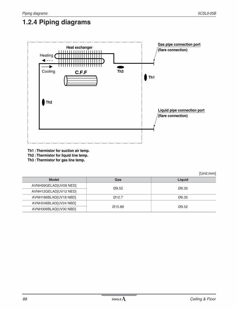
1.2.4 Piping diagrams
[Unit:mm]
Heat exchanger
Th3
Th1
Gas pipe connection port(flare connection)
Th2
Th1 : Thermistor for suction air temp.Th2 : Thermistor for liquid line temp.Th3 : Thermistor for gas line temp.
Liquid pipe connection port(flare connection)
C.F.FCooling
Heating
Model Gas Liquid
AVNH09GELAD[UV09 NED]
AVNH12GELAD[UV12 NED]Ø9.52 Ø6.35
AVNH186BLAD[UV18 NBD] Ø12.7 Ø6.35
AVNH246BLAD[UV24 NBD]
AVNH306BLAD[UV30 NBD]Ø15.88 Ø9.52

Ceiling & Floor 89
Wiring diagrams5CSL0-05B
1.2.5 Wiring diagrams
1) Wiring diagrams
Models : AVNH09GELAD[UV09 NED], AVNH12GELAD[UV12 NED]
Connector Number Location Connector Number LocationCN-POWER AC power supply CN-TH2 Discharge pipe sensorCN-MOTOR BLDC fan motor output CN-TH1 Pipe and room sensorCN-DPUMP Drain pump output CN-HVB Air cleanerCN-AC/DC AC/DC connector CN-DOOR Step motorCN-DISPLAY Display CN-UD1 Step motorCN-FLOAT Float switch input CN-CC Central control
Models : AVNH186BLAD[UV18 NBD], AVNH246BLAD [UV24 NBD], AVNH306BLAD [UV30 NBD]

90 Ceiling & Floor
5CSL0-05BWiring diagrams
2) PCB
<UV09 NED, UV12 NED >
CN_ OPTION
CN_ DISPLAY
CN_ WRITE
CN_ CENTRALCONTROL
CN_ REMO
CN_ PIPE/OUT
CN_ PIPE/IN CN_ ROOM
SW01
CN_ POWER
CN_ DOOR CN_ MOTOR1CN_ MOTOR2
CN_ vain 1CN_ vain 1
CN_ vain 2CN_ vain 2
CN_ vain 1
CN_ vain 2
CN-POWER
CN-MOTOR CN-DISP CN-REMO
CN-FLOAT
CN-ROOM
CN-PIPE1
CN-CC
CN-PIPE2
<UV18 NBD,UV24 NBD, UV 30 NBD >
CVT 1:Communication 2:Cycle 3:Group control 4:Dry Contact 5:Install 6:Heater link 7:Ventilator link 8:Extra
Off (Factory Set) On H/P Master Manual Ceiling Off Off -
On Off C/O Slave Auto Bottom On On -

Ceiling & Floor 91
Air flow and temperature distributions (reference data)5CSL0-05B
1.2.6 Air flow and temperature distributions (reference data)
2.7m
Air velocity [m/s]
2m
1m
0m0m1m2m3m4m5m6m7m8m
Temperature [˚C]
2.7m
Air velocity [m/s]
2m
1m
0m0m1m2m3m4m5m6m7m8m
Temperature [˚C]
0.51.0
1.5
0.51.0
1.5
2.02.0
2.7m
2m
1m
0m0m1m2m3m4m5m6m7m8m
24
22
18
2.7m
2m
1m
0m0m1m2m3m4m5m6m7m8m
2427
33
Cooling HeatingDischarge angle:45° Discharge angle:50°
Models : 5.0 kW - installation on floor or wall
Cooling Heating
2.7m
Air velocity [m/s]
2m
1m
0m0m1m2m3m4m5m6m7m8m
2.7m
Temperature [˚C]
2m
1m
0m0m1m2m3m4m5m6m7m8m
1.0
2.0
1.5
0.5
24 22
2018
2.7m
Air velocity [m/s]
2m
1m
0m0m1m2m3m4m5m6m7m8m
2.7m
Temperature [˚C]
2m
1m
0m0m1m2m3m4m5m6m7m8m
2.01.5
1.0
0.5
33
30
27
2421
Discharge angle:45° Discharge angle:50°
Models : 5.0 kW - installation on ceilling

92 Ceiling & Floor
5CSL0-05BSound levels
1.2.7 Sound levels
1m
Microphone1m
Notes:- Data is valid at nominal operation condition- Reference accoustic pressure OdB = 20μPa - Sound level will vary depending on a range of factors such as the construction(acoustic absorption coefficient) of particular room in which the equipment is installed.- The operating conditions are assumed to be standard.
Octave Band Center Frequency (Hz)
Sou
nd P
ress
ure
Leve
l (dB
re
20μP
a )
Octave Band Center Frequency (Hz)
Sou
nd P
ress
ure
Leve
l (dB
re
20μP
a )
Octave Band Center Frequency (Hz)
Sou
nd P
ress
ure
Leve
l (dB
re
20μP
a )
10
20
30
40
50
60
70
80
90
63 125 250 500 1000 2000 4000 8000
NC-15
NC-70
NC-65
NC-60
NC-55
NC-50
NC-45
NC-40
NC-35
NC-30
NC-25
NC-20
10
20
30
40
50
60
70
80
90
63 125 250 500 1000 2000 4000 8000
NC-15
NC-70
NC-65
NC-60
NC-55
NC-50
NC-45
NC-40
NC-35
NC-30
NC-25
NC-20
10
20
30
40
50
60
70
80
90
63 125 250 500 1000 2000 4000 8000
NC-15
NC-70
NC-65
NC-60
NC-55
NC-50
NC-45
NC-40
NC-35
NC-30
NC-25
NC-20
Octave Band Center Frequency (Hz)
Sou
nd P
ress
ure
Leve
l (dB
re
20P
a )
10
20
30
40
50
60
70
80
90
63 125 250 500 1000 2000 4000 8000
NC-15
NC-70
NC-65
NC-60
NC-55
NC-50
NC-45
NC-40
NC-35
NC-30
NC-25
NC-20
Sound pressure levelAVNH09GELAD[UV09 NED] AVNH12GELAD[UV12 NED] AVNH186BLAD [UV18 NBD] AVNH246BLAD [UV24 NBD]
AVNH306BLAD [UV30 NBD]
Overall

Ceiling & Floor 93
5CSL0-05B Controller
■ Wireless remote controllerThe remote controller transmits the signals to the system.
1. Start/Stop bttonOperation starts when this button is pressedand stops when the button is pressed again.
2. Operation mode selection buttonUsed to select the operation mode.
3. Room temperature setting buttonsUsed to select the room temperature.
4. Indoor fanspeed selectorUsed to select fan speed in four stepslow, medium, high and CHAOS.
5. Jet coolUsed to start or stop the speed cooling/heating. (Speed cooling/heating operates super high fanspeed.)
6. Chaos swing buttonUsed to stop or start louver movement and setthe desired up/down airflow direction.
7. On/Off timer buttonsUsed to set the time of starting and stoppingoperation.
8. Time setting buttonsUsed to adjust the time.
9. Timer set/Cancel buttonUsed to set the timer when the desired time isobtained and to cancel the Timer operation.
10. Sleep mode auto buttonUsed to set sleep mode auto operation.
11. Air circulation buttonUsed to circulate the room air without cooling orheating.
12. Room temperature checking buttonUsed to check the room temperature.
13. PLASMA(Optional)Used to start or stop the plasma-purificationfunction.
14. Reset buttonInitialize remote controller.
15. 2nd F buttonUsed prior to using modes printed in blue at thebottom of buttons.
(Heat Pump)
AUTO CLEANON OFF
CANCEL
SET
Cooling operation
Auto operation
Healthy dehumidification operation
Flip-up door(opened)
Heating operation
Signal transmitter
• Cooling model( ), Heat pump model( )
5 1
3
10
9
12
15
6
4
2711813
14
Operation mode
1.2.8 Controller