liquid carbon dioxide systems - huntington beach, california · liquid carbon dioxide systems –...
TRANSCRIPT
Guideline for Liquid Carbon Dioxide Systems
June 16, 2015
This document was developed by the Orange County Fire Chief’s Association, Orange County Fire Marshal Committee based upon the 2013 California Fire Code. The Orange County Fire Marshal Committee recommends that this document be used by local jurisdictions in order to provide a uniform approach to the life safety issues associated with liquid carbon dioxide systems.
Liquid Carbon Dioxide Systems – Orange County Fire Marshals June 16, 2015
Page 2
TABLE OF CONTENTS
PURPOSE .................................................................................................................... 3
SCOPE ......................................................................................................................... 3
1 PERMITS .......................................................................................................... 4 1.1 Construction Permit ................................................................................ 4
1.2 Operational Permit .................................................................................. 4
2 HAZARDOUS MATERIAL BUSINESS PLAN .................................................... 4
3 GENERAL FIRE CODE REQUIREMENTS ....................................................... 4 3.1 Maximum Allowable Quantities ............................................................... 5
3.2 Systems, equipment and processes ....................................................... 5 3.2.1 Tank ............................................................................................. 5
3.2.2 Piping ........................................................................................... 5 3.3 MSDS (Material Safety Data Sheets)...................................................... 6 3.4 Hazard identification signs ...................................................................... 7
3.5 Markings ................................................................................................. 7
3.6 General safety precautions ..................................................................... 7 3.7 Ventilation ............................................................................................... 8 3.8 Pressure relief device ............................................................................. 8
3.9 Marking ................................................................................................... 8 3.10 Secure .................................................................................................... 9 3.11 Venting .................................................................................................... 9
3.12 Egress ..................................................................................................... 10 3.13 Lighting ................................................................................................... 10
4 RECOMMENDATIONS ..................................................................................... 10
4.1 Detection and alarm systems .................................................................. 10 4.2 Warning sign ........................................................................................... 11
5 HOW TO DETERMINE WHETHER THE PERMISSIBLE EXPOSURE LIMIT (PEL) CAN BE EXCEEDED. ................................................................... 12
6 SELF-EVALUATION CHECKLIST ..................................................................... 13

Liquid Carbon Dioxide Systems – Orange County Fire Marshals June 16, 2015
Page 3
PURPOSE
Liquid carbon dioxide (CO2) is a liquefied compressed gas that can be found in compressed gas cylinders with a gas phase above the liquid phase or in insulated containers containing refrigerated liquid carbon dioxide. Carbon dioxide gas is an asphyxiant that can displace oxygen to dangerous and even fatal levels.
Liquid carbon dioxide systems are an area of concern due to its widespread presence in assembly occupancies; especially restaurants (see Figure 1). Restaurants often receive bulk deliveries of CO2 in liquid form. Frequently there is a lack of knowledge by owners, managers, staff, and patrons regarding the risks associated with these systems. Some vendors have also been placing them in occupancies with no building or fire department oversight. Additionally, firefighters need to have appropriate advanced knowledge of their locations in the event of an emergency response at these locations.
Figure 1. Illustration of Typical Bulk CO2 Installation (Source: Carbo-Mizer)
SCOPE
This guideline applies to insulated liquefied carbon dioxide systems only.
Where there is an interpretation of the California Fire Code (CFC), this document identifies the Orange County Fire Marshal (OCFM) Group’s collective agreement with the term “OCFM” and is shown in bold italic print.
Liquid Carbon Dioxide Systems – Orange County Fire Marshals June 16, 2015
Page 4
1 PERMITS
1.1 Construction Permit
A fire construction permit is required under CFC Section 105.7.3 if a CO2 system exceeds the levels requiring a fire code operational permit (6,000 cubic feet at standard temperature and pressure (STP)). This is approximately 687 pounds of CO2. Restaurant installations of carbonated beverage systems are typically 250 to 550 pounds. However, other locations such as swimming pool facilities and large assembly occupancies may exceed 687 pounds of CO2 and therefore will require a fire construction permit.
For more information: Contact your city’s Building and Fire Department to apply for and obtain appropriate building and fire construction permits.
1.2 Operational Permit
If the facility has 6,000 cubic feet or more of CO2, a compressed gas fire code operational fire permit is required.
For more information: Contact your city’s Fire Department to apply for this permit.
2 HAZARDOUS MATERIAL BUSINESS PLAN
The owner of the business using the liquid CO2 system that exceeds 1,000 cubic feet (STP) is also responsible for submitting a Hazardous Materials Business Plan (HMBP) and applicable documents to the California Environmental Reporting System (CERS) or local portal on an annual basis, or as otherwise required by state law. This is specific to carbon dioxide, per the Health & Safety Code (H&S) 25505(a)(5)(C).
For more information: Contact your city’s Certified Unified Program Agency/Participating Agency (CUPA/PA) for information on the HMBP program.
3 GENERAL FIRE CODE REQUIREMENTS
General requirements take into consideration that liquid CO2 is regulated as an inert compressed gas. As a hazardous material and without additional local ordinances, liquid CO2 is regulated under California Fire Code (CFC), Chapter 50 and Chapter 53. The following code requirements are not an all inclusive list; however they are a consolidation of the main areas of focus.

Liquid Carbon Dioxide Systems – Orange County Fire Marshals June 16, 2015
Page 5
Locally established ordinances specific to CO2 may have different requirements than contained in this guideline.
3.1 Maximum Allowable Quantities
There are no maximum allowable quantities (MAQs) per the CFC. MAQs are “not applicable.”
[CFC 5003.1.1]
3.2 Systems, equipment and processes
3.2.1.1 Tank
The tank must be designed and constructed in accordance with approved standards.
[CFC 5003.2.1]
Designed, fabricated, tested, marked with specifications of manufacture and maintained in accordance with the regulations of Department of Transportation (DOTn) 49, Code of Federal Regulations (CFR) Part 100-185 or the (American Society of Mechanical Engineers (ASME) Boiler and Pressure Vessel Code Section VIII (see Figure 2).
[CFC 5303.2]
Figure 2. Example of a CO2 Manufacture Plate
3.2.2 Piping
3.2.2.1 Identify piping
Piping must be identified in accordance with ASME A13.1 (e.g., contents and direction, CARBON DIOXIDE ).
[CFC 5003.2.2.1]
Liquid Carbon Dioxide Systems – Orange County Fire Marshals June 16, 2015
Page 6
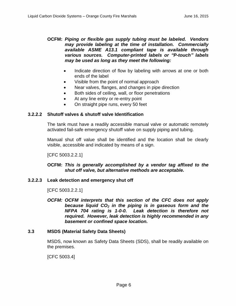
OCFM: Piping or flexible gas supply tubing must be labeled. Vendors may provide labeling at the time of installation. Commercially available ASME A13.1 compliant tape is available through various sources. Computer-printed labels or “P-touch” labels may be used as long as they meet the following:
Indicate direction of flow by labeling with arrows at one or both ends of the label
Visible from the point of normal approach
Near valves, flanges, and changes in pipe direction
Both sides of ceiling, wall, or floor penetrations
At any line entry or re-entry point
On straight pipe runs, every 50 feet
3.2.2.2 Shutoff valves & shutoff valve Identification
The tank must have a readily accessible manual valve or automatic remotely activated fail-safe emergency shutoff valve on supply piping and tubing.
Manual shut off value shall be identified and the location shall be clearly visible, accessible and indicated by means of a sign.
[CFC 5003.2.2.1]
OCFM: This is generally accomplished by a vendor tag affixed to the shut off valve, but alternative methods are acceptable.
3.2.2.3 Leak detection and emergency shut off
[CFC 5003.2.2.1]
OCFM: OCFM interprets that this section of the CFC does not apply because liquid CO2 in the piping is in gaseous form and the NFPA 704 rating is 1-0-0. Leak detection is therefore not required. However, leak detection is highly recommended in any basement or confined space location.
3.3 MSDS (Material Safety Data Sheets)
MSDS, now known as Safety Data Sheets (SDS), shall be readily available on the premises.
[CFC 5003.4]

Liquid Carbon Dioxide Systems – Orange County Fire Marshals June 16, 2015
Page 7
3.4 Hazard identification signs
Signs are required by the fire code official.
OCFM: Where liquid CO2 containers are located in buildings, visible National Fire Protection Association (NFPA) 704 hazardous identification signs displaying the following hazard ratings (Health-3; Flammablity-0; Reactivity-0; General Information-SA) (see Figure 3), shall be posted at specific entrances (e.g., storage room doors, exterior doors closest to tanks, clearly visible on walls above the tank) where carbon dioxide tanks are stored, as determined by the local fire code official.
Figure 3. NFPA 704 Sign for Liquid CO2
[CFC 5003.5]
3.5 Markings
Individual containers shall be marked or labeled in an approved manner.
[CFC 5003.5.1]
OCFM: The CO2 tank(s) are to be marked with “CARBON DIOXIDE” and NFPA 704 signs. The markings should be facing outward such that employees and emergency responders can see the markings clearly.
3.6 General safety precautions
Individuals responsible for the operations of an area shall be familiar with the chemical nature of the hazardous materials stored and the appropriate mitigating actions necessary in the event of a fire, leak or spill.
[CFC 5003.9.1]
Liquid Carbon Dioxide Systems – Orange County Fire Marshals June 16, 2015
Page 8
Note: Recurrent training is also necessary as part of the Hazardous Material Business Plan requirements.
3.7 Ventilation
If a fire code operational permit for compressed gas is required, then ventilation is required.
[CFC 5004.3]
Indoor storage and use areas and storage buildings shall be provided with mechanical exhaust ventilation or natural ventilation.
[CFC 5307.2]
OCFM: If the system has over 6,000 cubic feet at standard temperature and pressure (STP) of CO2, building and fire construction permits are required. Ventilation shall be addressed in the plan submission.
3.8 Pressure relief device
Pressure relief devices shall be designed and provided in accordance with Compressed Gas Association (CGA) S1.1, CGA S-1.2, CGA S-1.3, or the ASME Boiler and Pressure Vessel Code, Section VIII.
[CFC 5303.3.2]
3.9 Marking
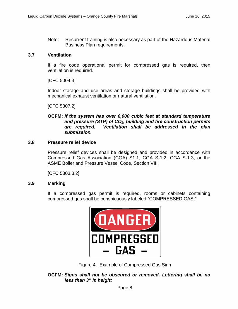
If a compressed gas permit is required, rooms or cabinets containing compressed gas shall be conspicuously labeled “COMPRESSED GAS.”
Figure 4. Example of Compressed Gas Sign
OCFM: Signs shall not be obscured or removed. Lettering shall be no less than 3” in height

Liquid Carbon Dioxide Systems – Orange County Fire Marshals June 16, 2015
Page 9
[CFC 5003.5.1]
Stationary and portable compressed gas tanks shall be marked:
Name of gas, visible from any approach (Stationary tanks)
Marked in accordance with CGA C-7 (Portable tanks)
Piping marked in accordance with ASME A13.1 including content and direction of flow, provided at each valve and wall/ceiling penetration
[CFC 5303.4]
3.10 Secure
Storage areas shall be secured against unauthorized entry and safe-guarded in a manner approved by the fire code official.
[CFC 5003.9.2]
Tanks shall be secured against accidental dislodgment and against access by unauthorized personnel.
Liquid CO2 containers shall be secured to prevent falling caused by contact, vibration or seismic activity by one of the following methods:
Securing containers to a fixed object with one or more noncombustible restraints
Securing containers on a cart or other mobile device designed for the movement of compressed gas containers
Securing container to or within a rack, framework, cabinet or similar assembly designed for such use
[CFC 5303.5]
OCFM: Secure in accordance with the tank manufacturer’s guidelines. Tanks may also be secured with floor bolts or with straps anchored to the walls(s). Due to extreme weight of larger tanks and contents, chains may not be used unless approved by the local fire code official.
3.11 Venting
To approved location.
[CFC 5305.5]

Liquid Carbon Dioxide Systems – Orange County Fire Marshals June 16, 2015
Page 10
OCFM: Venting is a normal function of these systems. The system will, from time to time, vent small amounts of gas to maintain consistent pressure. OCFM recommends venting to the outdoors (preferred), or indoors to a well-ventilated area, out of traffic patterns and above ground away from cellars or low areas where the gas can collect.
3.12 Egress
The tank area shall be unobstructed and does not interfere with means of egress.
[CFC 1030.3]
OCFM: The pathway to the CO2 tank(s) and emergency shutoffs should be free from any obstacles. Do not store items that may block access to any portion of the tank, including the tank top. Allow enough space for a person to access shutoffs and read all warning labels.
3.13 Lighting
Approved lighting by natural or artificial means shall be provided.
[CFC 5303.15]
4 RECOMMENDATIONS
4.1 Detection and alarm systems
CO2 is an asphyxiant hazard with the largest risk associated with confined areas or below grade areas. See Section 5 for details on how this is calculated.
OCFM: OCFM recommends the installation of a gas detection and alarm system in basements or confined locations in which a catastrophic release would result in the permissible exposure limit (PEL) being exceeded. The system should be capable of detecting and notifying building occupants of a gas release that creates carbon dioxide vapors in excess of its permissible exposure level (PEL).
Refer to Section 5 for instruction on how to determine the PEL for an enclosed location
The gas detector must be a carbon dioxide detector and not an oxygen detector

Liquid Carbon Dioxide Systems – Orange County Fire Marshals June 16, 2015
Page 11
4.2 Warning sign
Warning signs are recommended as an industry standard (CGA G-6, Carbon Dioxide and NFPA 55: 13.2.3).
OCFM: OCFM recommends warning signs be posted at the entrance to the storage area.
WARNING – CARBON DIOXIDE GAS
VENTILATE THE AREA BEFORE ENTERING
A High Carbon Dioxide (CO2) gas concentration in this area can cause asphyxiation
Figure 5. Example of Warning Sign
Liquid Carbon Dioxide Systems – Orange County Fire Marshals June 16, 2015
Page 12
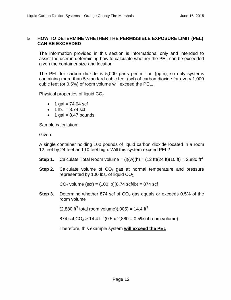
5 HOW TO DETERMINE WHETHER THE PERMISSIBLE EXPOSURE LIMIT (PEL) CAN BE EXCEEDED
The information provided in this section is informational only and intended to assist the user in determining how to calculate whether the PEL can be exceeded given the container size and location.
The PEL for carbon dioxide is 5,000 parts per million (ppm), so only systems containing more than 5 standard cubic feet (scf) of carbon dioxide for every 1,000 cubic feet (or 0.5%) of room volume will exceed the PEL.
Physical properties of liquid CO2
1 gal = 74.04 scf
1 lb. = 8.74 scf
1 gal = 8.47 pounds
Sample calculation:
Given:
A single container holding 100 pounds of liquid carbon dioxide located in a room 12 feet by 24 feet and 10 feet high. Will this system exceed PEL?
Step 1. Calculate Total Room volume = (l)(w)(h) = (12 ft)(24 ft)(10 ft) = 2,880 ft3
Step 2. Calculate volume of CO2 gas at normal temperature and pressure represented by 100 lbs. of liquid CO2
CO2 volume (scf) = (100 lb)(8.74 scf/lb) = 874 scf
Step 3. Determine whether 874 scf of CO2 gas equals or exceeds 0.5% of the room volume
(2,880 ft3 total room volume)(.005) = 14.4 ft3
874 scf CO2 > 14.4 ft3 (0.5 x 2,880 = 0.5% of room volume)
Therefore, this example system will exceed the PEL
Liquid Carbon Dioxide Systems – Orange County Fire Marshals June 16, 2015
Page 13
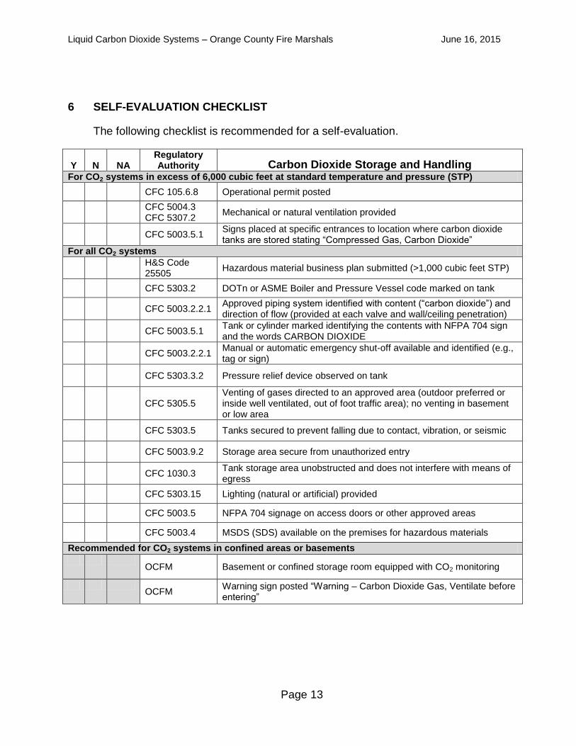
6 SELF-EVALUATION CHECKLIST
The following checklist is recommended for a self-evaluation.
Y N NA Regulatory Authority Carbon Dioxide Storage and Handling
For CO2 systems in excess of 6,000 cubic feet at standard temperature and pressure (STP)
CFC 105.6.8 Operational permit posted
CFC 5004.3 CFC 5307.2
Mechanical or natural ventilation provided
CFC 5003.5.1 Signs placed at specific entrances to location where carbon dioxide tanks are stored stating “Compressed Gas, Carbon Dioxide”
For all CO2 systems
H&S Code 25505
Hazardous material business plan submitted (>1,000 cubic feet STP)
CFC 5303.2 DOTn or ASME Boiler and Pressure Vessel code marked on tank
CFC 5003.2.2.1 Approved piping system identified with content (“carbon dioxide”) and direction of flow (provided at each valve and wall/ceiling penetration)
CFC 5003.5.1 Tank or cylinder marked identifying the contents with NFPA 704 sign and the words CARBON DIOXIDE
CFC 5003.2.2.1 Manual or automatic emergency shut-off available and identified (e.g., tag or sign)
CFC 5303.3.2 Pressure relief device observed on tank
CFC 5305.5 Venting of gases directed to an approved area (outdoor preferred or inside well ventilated, out of foot traffic area); no venting in basement or low area
CFC 5303.5 Tanks secured to prevent falling due to contact, vibration, or seismic
CFC 5003.9.2 Storage area secure from unauthorized entry
CFC 1030.3 Tank storage area unobstructed and does not interfere with means of egress
CFC 5303.15 Lighting (natural or artificial) provided
CFC 5003.5 NFPA 704 signage on access doors or other approved areas
CFC 5003.4 MSDS (SDS) available on the premises for hazardous materials
Recommended for CO2 systems in confined areas or basements
OCFM Basement or confined storage room equipped with CO2 monitoring
OCFM
Warning sign posted “Warning – Carbon Dioxide Gas, Ventilate before entering”