linemaster 200 continuous-line recorder - abb group 200 continuous-line recorder operating manual...
TRANSCRIPT

LineMaster 200 Continuous-line recorder
Operating manual 42/43-27 EN Rev. 03

Contents
Page
Remarks . . . . . . . . . . . . . . . . . . . . . . . . . . . . . . . . . . 2
Short description . . . . . . . . . . . . . . . . . . . . . . . . . 2
Installation and Commissioning
Scope of delivery . . . . . . . . . . . . . . . . . . . . . . . . . . . . . . 31. Mounting location . . . . . . . . . . . . . . . . . . . . . . . . . . . 32. Mounting . . . . . . . . . . . . . . . . . . . . . . . . . . . . . . . . . . 43. Connecting the instrument . . . . . . . . . . . . . . . . . . . . . 5
Connecting the input signal . . . . . . . . . . . . . . . . . . . . . 5Connecting the power supply . . . . . . . . . . . . . . . . . . . 5
4. Fitting the chart . . . . . . . . . . . . . . . . . . . . . . . . . . . . . 65. Fitting the fibre pen / print unit . . . . . . . . . . . . . . . . . . 76. Switching on the unit . . . . . . . . . . . . . . . . . . . . . . . . . 87. Positioning the chart . . . . . . . . . . . . . . . . . . . . . . . . . . 8
Operation
Removing the chart . . . . . . . . . . . . . . . . . . . . . . . . . . . . . . 9Withdrawing chart paper from take-up roll . . . . . . . . . . . . . 9Changing the chart speed . . . . . . . . . . . . . . . . . . . . . . . . 10
Retrofitting
Changing measuring ranges . . . . . . . . . . . . . . . . . . . . . . 11Replacing scales . . . . . . . . . . . . . . . . . . . . . . . . . . . . . . 14Replacing the measuring point name plate . . . . . . . . . . . . 14
Maintenance
Replacing the fuse . . . . . . . . . . . . . . . . . . . . . . . . . . . . . 15
Appendix
Technical data . . . . . . . . . . . . . . . . . . . . . . . . . . . . . . . 16Packaging for transport orfor return to manufacturer . . . . . . . . . . . . . . . . . . . . . . . 19
Depiction of reference symbols
<Key> Inscription of the keys on the display and operatorcontrol unit.
Reading Non-flashing readings in the displayReading Flashing readings in the display
The indications “right”, “left”, “top” or “bottom” imply that theviewer is looking at the front panel of the instrument unlessstated otherwise.
Important Instructions foryour Safety!
Please read and observe!
Correct and safe operation of the apparatus calls forappropriate transportation and storage, expert installationand commissioning as well as correct operation and me-ticulous maintenance.
Only those persons conversant with the installation, com-missioning, operation and maintenance of similar appara-tuses and who possess the necessary qualifications areallowed to work on the apparatus.
Please take note of the contents of this Operating Manualand the safety regulations affixed to the apparatus.
The directives, norms and guidelines mentioned in thisOperating Manual are applicable in the Federal Republicof Germany. When using the apparatus in other countries,please observe the national regulations prevailing in therespective country.
This apparatus has been designed and tested in accor-dance with DIN EN 61010-1„Safety requirements for elec-tronic, process measuring and laboratory instruments“ andhas been supplied in a safe condition. In order to retainthis condition and to ensure safe operation, the safetyinstructions in this Operating Manual bearing the headline„Attention“ must be observed. Otherwise, persons can beendangered and the apparatus itself as well as otherequipment and facilities can be damaged.
If the information in this Operating Manual should proveto be insufficient in any point, the Service Department willbe delighted to give you more information.
Short description
The recorder is a microprocessor-controlled continuous-linerecorder with 1 to 4 line channels or 1 to 3 line channels and 1printer channel. The printer channel enables the recording of ameasured value and creates text printouts.
The recorder is connected to the transmitter and is to be used formeasuring process signals. The measuring channels are elec-trically separated from each other and unearthed.
Complementary publication
Instructions for parameter settingInterface Description
R-18908
2 Contents • Remarks

Installation and Commissioning
Scope of delivery
The recorder is supplied with the following:− 1 operating manual− 2 mounting brackets Be− 1 fibre pen Fe for each measuring channel− 1 print unit De (option)− 1 pack of fanfold chart Fp or 1 roll chart Sr− 24 plug-in jumpers for universal version− depending on the order the corresponding number of screw-
plug terminals Sk, Sub-D connector, 9-pin and ruler(s).
Fig. 1 Scope of deliveryZ-17538 Be Mounting brackets
De Print unit (option)Fe Fibre pensFp Fanfold chartSk Screw-plug terminalsSr Roll chart
1. Mounting location
Mounting orientationLateral −30°...0...+30°Inclination backwards 20°, forwards 20°
Ambient temperature0...50 °C
Relative humidity≤ 75 % annual average, max. relative humidity ≤ 85 % duringoperation. Avoid condensation!
Installation • Commissioning 3

2. Mounting
Fig. 2 Dimensional drawing (dimensions in mm)Z-17464 left bottom: panel cutout
Fig. 3 Mounting the bracketsZ-17539 Be Mounting bracket
Mounting in panels
1. Fit the instrument into the panel from the front.
2. Fit mounting brackets Be laterally into the fitting notches onthe case (see fig. 3).
NoteThe mounting brackets Be are designed for close-packedhorizontal and vertical mounting.
3. Align the mounting brackets Be vertically and tighten themequally.
Mounting in rack
1. Fasten 4 centering brackets.
2. Fit mounting brackets Be laterally into the fitting notches onthe case (see fig. 3).
3. Align the mounting brackets Be vertically and tighten themequally.
4 Installation • Commissioning

3. Connecting the instrument
CautionBefore all other connections are made the protective groundterminal must be connected to a protective conductor.
The unit can be dangerous if the protective conductor isinterrupted inside or outside the unit or if the protectiveground terminal is disconnected.
The unit may only be operated when properly installed.
Install a mains switch, with adequate switching capacity,within the reach of the mounting site so that the unit can bedisconnected at all poles from the mains. The protectiveaction of the protective conductor must not be negated.
The nominal current power of the protection equipment onthe side of the installation must not be over 16 A.
Fig. 4 Back panel and screw-plug terminalsZ-16529 “.” = 1 for channel blueZ-16784/1 “.” = 2 for channel redZ-17447 “.” = 3 for channel greenZ-17762 “.” = 4 for channel violetZ-17763
Connecting the input signal
Fasten signal lines (max. cross section 2 × 1 mm2) at thescrew-plug terminals.
Connecting the power supply
Fasten power supply lines (max. cross section 1 × 4 mm2 or2 × 1.5 mm2) at the screw-plug terminals. The cross sectionof the protective conductor must at least be equal to thecross section of the power supply line.
Installation • Commissioning 5

4. Fitting the chart
Chart unit for roll chart
Fig. 5 Unlocking the chart unitZ-17540 Eh Unlocking lever
Fig. 6 Chart unit for roll chartZ-17668 Ar Take-up roll
Ff Guide springPa Pressure plate flapPf Chart guide flapPm Chart storage recess
1. Unlock chart unit: Press unlocking lever Eh (see fig 5). Chartunit swings forwards. Remove chart unit in the direction ofthe arrow.
2. Open out pressure plate flap Pa.
3. Insert roll chart into the chart storage recess Pm.
4. Pull the chart beginning forwards to the sprocket wheel andengage the perforation with the sprocket wheel, making surethat the chart is parallel to the sprocket wheel.
5. Close the pressure plate flap Pa.
6. Open out the chart guide flap Pf.
7. Fit take-up roll Ar if necessary.
8. Close the chart guide flap Pf.
NoteHaving installed the chart unit in the recorder, the chart unitwinds itself automatically onto the take-up roll.
9. Fit chart unit in the chassis until it engages.
6 Installation • Commissioning
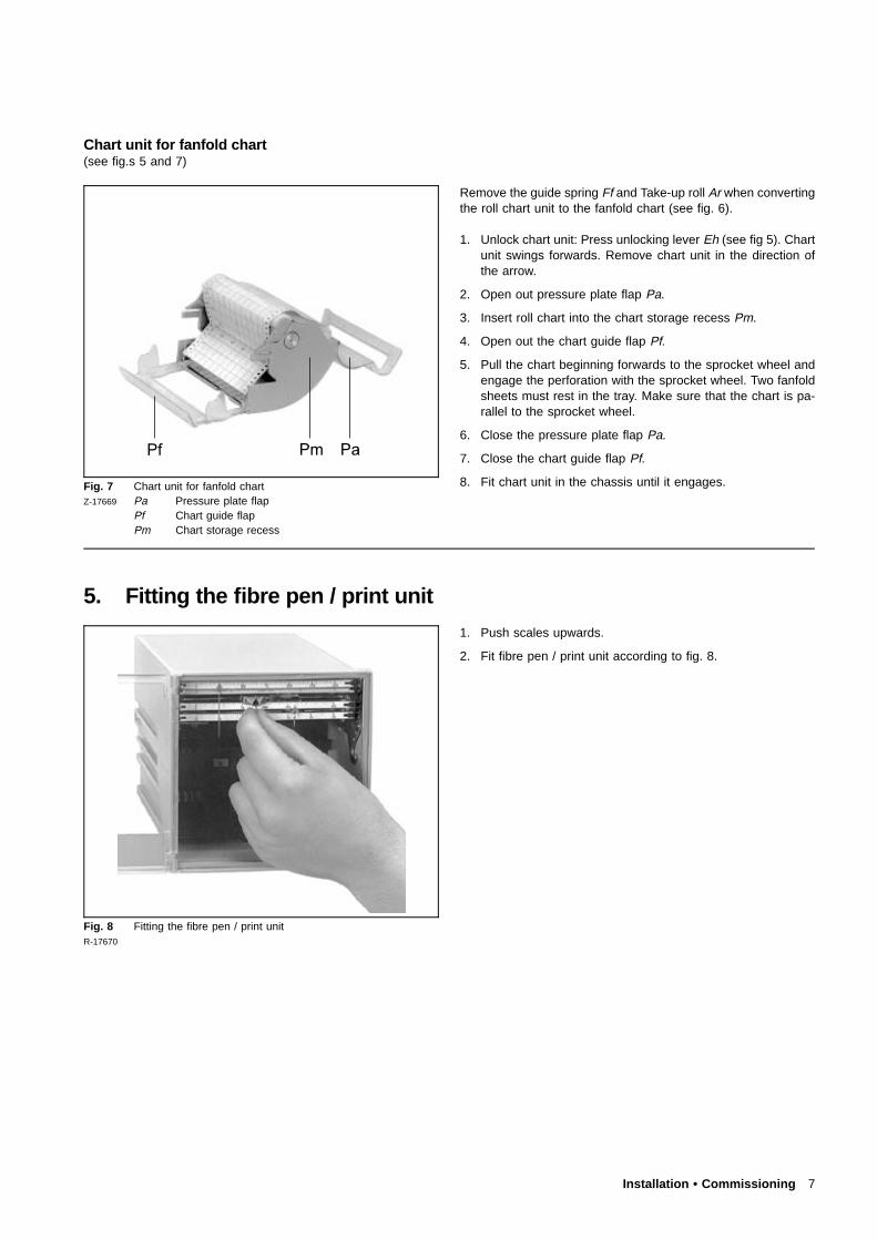
Chart unit for fanfold chart(see fig.s 5 and 7)
Fig. 7 Chart unit for fanfold chartZ-17669 Pa Pressure plate flap
Pf Chart guide flapPm Chart storage recess
Remove the guide spring Ff and Take-up roll Ar when convertingthe roll chart unit to the fanfold chart (see fig. 6).
1. Unlock chart unit: Press unlocking lever Eh (see fig 5). Chartunit swings forwards. Remove chart unit in the direction ofthe arrow.
2. Open out pressure plate flap Pa.
3. Insert roll chart into the chart storage recess Pm.
4. Open out the chart guide flap Pf.
5. Pull the chart beginning forwards to the sprocket wheel andengage the perforation with the sprocket wheel. Two fanfoldsheets must rest in the tray. Make sure that the chart is pa-rallel to the sprocket wheel.
6. Close the pressure plate flap Pa.
7. Close the chart guide flap Pf.
8. Fit chart unit in the chassis until it engages.
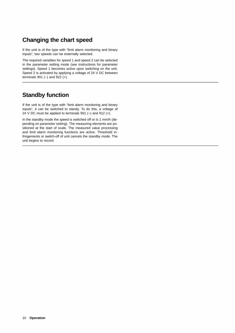
5. Fitting the fibre pen / print unit
Fig. 8 Fitting the fibre pen / print unitR-17670
1. Push scales upwards.
2. Fit fibre pen / print unit according to fig. 8.
Installation • Commissioning 7

Fig. 9 Display and operator control unitR-17671
It is more convenient to fit the fibre pens and print unit when theunit is switched on:
1. Unlock chart unit: Press unlocking lever (see fig. 5). Chartunit swings forwards. Remove chart unit in the direction ofthe arrow.
2. Remove chart unit.
3. Press < >. The measuring systems move to park position.
4. Push scales upwards.
5. Fit the fibre pens and print units.
6. Flap the scales downwards.
7. Press < >.
8. Fit chart unit in the chassis until it engages.
6. Switching on the unit
CautionBefore switching on, make sure that the operating voltageof the unit (see rating plate) corresponds to the voltage ofthe power supply.
Install a mains switch, with adequate switching capacity, withinthe reach of the mounting site so that the unit can be disconnec-ted at all poles from the mains. The protective action of the pro-tective conductor must not be negated.
7. Positioning the chart
Fig. 10 Positioning the chartZ-17672
1. Press the lower handle strips of chart unit towards the back.The chart is transported faster downwards.
2. Let go the handle strips once the green baseline has beenreached.
8 Installation • Commissioning

OperationRemoving the chart
Fig. 11 Removing the chartR-17673
The chart unit can remain in the unit when removing the chart.
Chart unit for chart
1. Open the chart guide flap downwards.
2. Remove take-up roll.
3. If necessary, tear off the chart at the perforation.
Chart unit for fanfold chart
1. Open the chart guide flap downwards.
2. Remove the fanfold pack.
3. If necessary, tear off the chart at the fold.
NoteTwo fanfold sheets must rest in the tray.
Withdrawing chart paper from take-up roll
Fig. 12 Withdrawing chart from take-up rollR-17674
1. Rotate flange without drive pinion by 45° and pull from take-up roll.
2. Hold chart as shown in fig. 11 and remove from axis.
3. Replace right flange and secure by rotating by 45°.
4. Fit take-up roll into chart unit. The drive pinion must be onthe right hand side.
5. Close chart guide flap.
Operation 9
Changing the chart speed
If the unit is of the type with “limit alarm monitoring and binaryinputs”, two speeds can be externally selected.
The required variables for speed 1 and speed 2 can be selectedin the parameter setting mode (see instructions for parametersettings). Speed 1 becomes active upon switching on the unit.Speed 2 is activated by applying a voltage of 24 V DC betweenterminals 901 (−) and 922 (+).
Standby function
If the unit is of the type with “limit alarm monitoring and binaryinputs”, it can be switched to standy. To do this, a voltage of24 V DC must be applied to terminals 901 (−) and 912 (+).
In the standby mode the speed is switched off or is 1 mm/h (de-pending on parameter setting). The measuring elements are po-sitioned at the start of scale. The measured value processingand limit alarm monitoring functions are active. Threshold in-fringements or switch-off of unit cancels the standby mode. Theunit begins to record.
10 Operation

RetrofittingCaution
When the apparatus is connected to its supply, the terminalsmay be live, and the opening of covers or removal of partsexcept those to which access can be gained by hand islikely to expose live parts.
The apparatus shall be disconneced from all voltage sour-ces before it is opened for any operations. Operations onthe opened apparatus under voltage must only be performedby an expert who is aware of the hazard involved.
Capacitors inside the apparatus may still be charged evenif the apparatus has been disconnected from all voltagesources.
Only fuses of the specified type and rated current may beused as replacements. Makeshift fuses must not be used.The fuse-holder may not be short-circuited.
Whenever it is likely that protection has been impaired, theapparatus shall be made inoperative and be secured againstany unintended operation.
It must be assumed that the protection has been impairedwhen− the apparatus has visible signs of damage,− the apparatus no longer functions,− the apparatus has been stored in unfavourable condi-
tions for a long time,− the apparatus has been subjected to adverse transport
conditions.
Changing measuring ranges
Standard version
The unit version with “Standard measuring range” is matched tothe measuring task using the keys of the display and operatorcontrol unit or via RS-485 interface (see parameter setting in-structions).
Universal version
The unit version with “Standard measuring range” is matched tothe measuring task using the keys of the display and operatorcontrol unit or via RS-485 interface (see parameter setting in-structions). A further hardware matching on the channel cardusing plug-in jumpers is necessary.
Hardware matching with plug-in jumpers
Fig. 13 As Retaining screwZ-18027 Vh Locking lever
Remove electronic unit
1. Loosen the retaining screws As (see fig. 13) and pull for-ward the measuring element carriage by approximately 2 cm.
2. Lift up the locking lever Vh (see fig. 13) whilst pulling for-ward the module simultaneously.
3. Pull out the plugs to the measuring elements and also theplug for the print channel.
Retrofitting 11
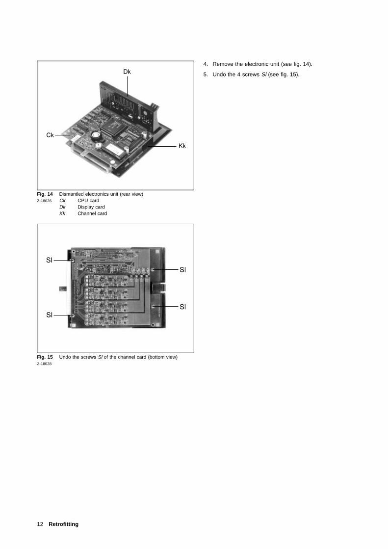
Fig. 14 Dismantled electronics unit (rear view)Z-18026 Ck CPU card
Dk Display cardKk Channel card
Fig. 15 Undo the screws Sl of the channel card (bottom view)Z-18028
4. Remove the electronic unit (see fig. 14).
5. Undo the 4 screws Sl (see fig. 15).
12 Retrofitting

Fig. 16 Arrangement of the plug-in jumpersZ-18128
Fig. 17 Arrangement of the plug-in jumpers according to type ofZ-18129 measurement and nominal measuring range
6. Arrange the plug-in jumpers on the component side of thechannel card according to channels. Fig. 16 shows the posi-tion of the plug-in jumpers assigned to the channels (X3...X6).
7. Arrange plug-in jumpers according to the desired type ofmeasurement and nominal measuring range (see fig. 17).
8. Fasten channel card Kk with the 4 screws Sl (see fig. 15).
9. Restore the plug connection to the measuring elements.
10. Fit the electronics unit into the recorder. Snap locking leverVh into place.
11. Push the measuring system carrier into housing and screwtight the retaining screw As (see fig. 13).
12. Switch on power supply and set the parameters of the re-quired measuring ranges (see instructions for parametersetting).
Retrofitting 13

Replacing scales
Fig. 18 Replacing scalesZ-17675
1. Remove fibre pens and print unit.
2. Undo the scale screws on the left.
3. Push scales to the right and disengage from scale screw.
4. Remove the scales by pulling them to the left.
5. Reinstall scales working in the opposite order.
6. Fit in the fibre pen.
7. Check the measuring system zero with the start of scale:1. Remove chart unit.2. Press <↵>. “SYS” is displayed.
The measuring systems go to the measuring systemzero.
3. Align scale with pointer and tighten scale screw.4. Fit chart unit.
Replacing the measuring point name plate
Fig. 19 Replacing the measuring point name plateZ-17676
Simply pull out the flexible measuring point designation plate andfit a new one.
14 Retrofitting

MaintenanceCaution
When the apparatus is connected to its supply, the terminalsmay be live, and the opening of covers or removal of partsexcept those to which access can be gained by hand islikely to expose live parts.
The apparatus shall be disconneced from all voltage sour-ces before it is opened for any operations. Operations onthe opened apparatus under voltage must only be performedby an expert who is aware of the hazard involved.
Capacitors inside the apparatus may still be charged evenif the apparatus has been disconnected from all voltagesources.
Only fuses of the specified type and rated current may beused as replacements. Makeshift fuses must not be used.The fuse-holder may not be short-circuited.
Whenever it is likely that protection has been impaired, theapparatus shall be made inoperative and be secured againstany unintended operation.
It must be assumed that the protection has been impairedwhen− the apparatus has visible signs of damage,− the apparatus no longer functions,− the apparatus has been stored in unfavourable condi-
tions for a long time,− the apparatus has been subjected to adverse transport
conditions.
Replacing fuses
Fig. 20 Replacing fuse SiZ-17677
CautionMake sure that only fuses with the required rated currentand of the specified type are used for replacement. The useof makeshift fuses and the short-circuiting of fuse-holder areprohibited.
When the apparatus is connected to its supply, terminalsmay be live, and the opening of covers or removal of partsexcept those to which access can be gained by hand islikely to expose live parts.
1. Unscrew the fuse holder.
2. Replace fuse Si.
3. Screw back the fuse holder.
Fuse rating230 V M 0.16 C115 V M 0.315 C24 V M 1.6 E
Maintenance 15

Technical data
Measuring section
Measuring deviation
Class 0.5 for left channels to IEC 484 referred to the nominalrangeClass 1 for measured value recording with printer system toIEC 484 referred to the nominal range
Where lower-range value and/or upper-range value shifted,additionally:
± (0.1% nominalrangespan
0.1)
Dead zone0.25 % of span
Response time2 s
Measured value dampingwith 1st order low-pass filtertime constant 0...60 s per measuring channel, parameteriz-able
Measurement variable / nominalranges
Standard version
Direct current0...20 mA; Ri = 50 Ω4...20 mA; Ri = 50 Ω±20 mA; Ri = 50 Ω
Direct voltage±10 V; Ri > 1 MΩ
Universal version
Direct current0...20 mA; Ri = 50 Ω4...20 mA; Ri = 50 Ω±20 mA; Ri = 50 Ω
Direct voltage±75 mV; Ri ≥ 2 MΩ±20 V; Ri > 200 kΩ
Thermocouples, Ri ≥ 2 MΩType B 100...+1820 °CType E 0...+1000 °CType J 0...+1200 °CType K 0...+1372 CType L 0...+ 900 °CType N 0...+1300 °CType R 0...+1769 °CType S 0...+1769 °CType T 0...+ 400 °CType U 0...+ 600 °C
Parameters can be set internally or externally for referencepoint, monitoring of sensor breakage can be set as aparameter
Resistance thermometersPt100 in 2- or 3-wire circuits−50...+500 °C; −50...+150 °C
Line resistancewith 2-wire circuitry max. 10 Ωwith 3-wire circuitry max. 40 Ω
Measuring ranges
Lower rangefrom 0...80 % of each nominal range can be set as a para-meter
Measuring scopefrom 20...100 % of each nominal range can be set as a para-meter.
Root-extraction function in direct current and direct voltage nomi-nal ranges can be set as a parameter.
Effects
±1 °C/10 K for internal reference junction correction
± (0.2 (0.05 nominalrangespan
0.05)) % / 10K
Reference temperature25 °C
Influence of supply voltage0.1 % for 24 V DC ±20 %0.1 % for 24 V AC +10...−15 %0.1 % for 115 V AC +10...−15 %0.1 % for 230 V AC +10...−15 %
Influence of AC parasitic voltages≤0.5 % of span
Influence of external magnetic field 1 mT≤0.5 % of span
Influence at mechanical stressduring and after the effect ±0.5 % of the span
Recording section
Scaleone graduation per measuring systemScale plate width 5 mmCharacter height 2 mm
16 Technical data

Display and operator control unit
Display (only for parameter definition)5-digit, 7-segment displayCharacter height 4 × 7 mm
Operationwith 3 keys
Recording
Arrangement of the measuring systems and colour assignment:
Version without printer channelNumber of line channels1 2 3 4
green x xred x x xblue x x x xviolet x
Version with printer channelNumber of line channels1 2 3
green xred x xblaux x x
Print.ch. violet
Trend recording
Fibre pen with ink reservoir. Content approx. 1.4 l, length of lineapproximately 1300 m. Distance between tips of fibre-tip recor-ding pens 2 mm.
Printing
Instead of the lower measuring system, a printer system for textprinting can be incorporated. Distance between blue fibre-tiprecording pen and print head 6 mm. In addition to text printout,the printer system can be used to record a measured value.Measured values are recorded in the form of a dotted line withequidistant dot spacing. Ink reserve of the print head approxi-mately 1,500,000 dots.
Alphanumeric text print
1. 8 text lines with 16 characters each.A time printout is appended to each text line. Initiation cyclic,at parameterizable intervals or event-dependent by way ofinternal alarm values or external actuation (binary inputs).
2. Printout, paper feed, date and time.Initiation when unit is switched on and on paper feed switch-over.
3. Printout of time and date.Initiation cyclic, at parameterizable intervals or event-depen-dent by external actuation.
4. Print of current measured values.Initiation cyclic, at parameterizable intervals or event-depen-dent by internal/external actuation.
5. Printout of double lines allocated to measuring points.1st line: Scaling line with channel indentication and print-
out of unit.2nd line: Measuring point-specific text with max. 32 charac-
ters.6. Listing of all active parameters.
Operating manual in parameter-setting mode.
Text printingonly possible at paper feeds ≤240 mm/h
Font sizeapproximately 1.5 mm × 2 mm
Chart speeds0; 2.5; 5; 10; 20; 30; 60; 120; 240; 300; 600; 1200 mm/hOption: Speed is externally adjustable
Chart32 m roll chart or 16 m fanfold chart
Visible diagram length60 mm
Recording width100 mm (chart width 120 mm, DIN 16 230)
Chart feed-in (with roll chart)via automatic catch of fresh paper by take-up reel. Capacityof take-up reel 32 m.
Power supply
UC power supply unit
24 V AC/DC ±20 %
Power consumptionat max. complement approximately 15 W / 20 VA
AC power supply unit
24 AC / 115 AC / 230 V AC, +10...−15 %
Frequency range47.5...63 Hz
Power consumptionat max. complement approximately 20 W / 25 VA
RS 485 interface
− for parameter-setting− Link to higher-order systems for bidirectional data
transmission. The data protocol is based on the PROFIBUSstandard.
Technical data 17
Options
Alarm value monitoring
2 alarm values per channel for absolute value monitoring. 4internal relays can be freely assigned to the alarm values.
OutputNO contact − the contacts are linked to each other on oneside.Contact loadmax. 30 V / 100 mA; cos ϕ ≥ 0.5 (only functional extra-lowvoltage circuits may be connected)
Event marking (only version with printer channel)2 markers possibleRecording at approximately 2 % and 5 % recording widthControl voltage: 24 V DC / 6 mA external
External speed changeoverControl voltage: 24 V DC / 6 mA external
Standby functionControl voltage: 24 V DC / 6 mA external
General and Safety Data
Environmental capabilities
Climate class3K3 according to DIN IEC 721-3-3
Ambient temperature0...25...50 °C
Transport and storage temperature−40...+70 °C
Relative humidity (during operation)≤ 75 % year average, max. 85 %Avoid condensation!Note effect of atmospheric humidity on the chart paper ac-cording to DIN 16 234.
Mechanical features
Testedaccording to DIN IEC 68-2-27 and DIN IEC 68-2-6
TransportImpact 30g / 18 msVibration 2g / 5...150 Hz
During oprationVibration 0.5g / ±0.04 mm / 5...150 Hz / 3 × 2 cycles
Electromagnetic compatibility
The protection targets of the EMC directive 89/336/EEC withregard to radio interference suppression according to EN 55 011and to interference resistance according to EN 50082-2 are met.
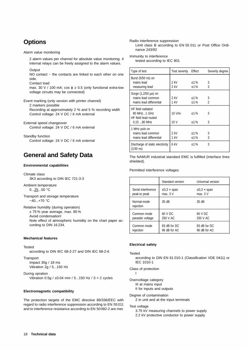
Radio interference suppressionLimit class B according to EN 55 011 or Post Office Ordi-nance 243/92
Immunity to interferencetested according to IEC 801
The NAMUR industrial standard EMC is fulfilled (interface lines
Type of test Test severity Effect Severity degree
Burst (5/50 ns) onmains leadmeasuring lead
2 kV2 kV
≤1 %≤1 %
33
Surge (1,2/50 µs) onmains lead commonmains lead differential
2 kV1 kV
≤1 %≤1 %
32
HF field radiated80 MHz...1 GHz
HF field lead routed0,15 ...80 MHz
10 V/m
10 V
≤1 %
≤1 %
3
3
1 MHz puls onmains lead commonmains lead differential
2 kV1 kV
≤1 %≤1 %
33
Discharge of static electricity(1/30 ns)
6 kV ≤1 % 3
shielded).
Permitted interference voltages
Standard version Universal version
Serial interferencepeak-to peak
≤0,3 × spanmax. 3 V
≤0,3 × spanmax. 3 V
Normal-moderejection
35 dB 35 dB
Common modeparasitic voltage
60 V DC250 V AC
60 V DC250 V AC
Common moderejection
83 dB for DC96 dB for AC
83 dB for DC96 dB for AC
Electrical safety
Testedaccording to DIN EN 61 010-1 (Classification VDE 0411) orIEC 1010-1
Class of protectionI
Overvoltage categoryIII at mains inputII for inputs and outputs
Degree of contamination2 in unit and at the input terminals
Test voltage3.75 kV measuring channels to power supply2.2 kV protective conductor to power supply
18 Technical data

Functional extra low-voltage with safe isolation (PELV)
between mains inputs − measuring inputs, control inputs, inter-face lines according to VDE 0100 part 410 and VDE 0106 part101
Connection, case and mounting
Electrical connectionsDegree of protection IP 20Theaded-head terminals for measuring inputs, control inputsand alarm value relay outputs.Max. wire cross-section 2 × 1 mm2
Screw-plug terminals for mains connectionMax. wire cross-section 4 mm2 or 2 × 1.5 mm2
RS 485 interface via 9-pin Sub-D connector
CaseMoulded plastic for panel or rack (dimensions see fig. 2)
Degree of case protection according to DIN 40 050Front IP 54Back IP 20
Colour of casepebble grey according to RAL 7032
Case doorMoulded materialOption: Metal frame door with glass pane nonreflecting
Mounting of casewith 2 mounting brackets (optionally for panel or rack), forrack mounting centering brackets required. Max. width of gridrod = 40 mm.
Mounting orientationLateral −30°...0...+30°Inclination backwards 20°Inclination forwards 20°
Mounting distancehorizontally or vertically 0 mm, case door must open at a100° angle.
Massapprox. 3.5 kg
Settings Basic Parameters
If no individual parameter-setting is requested when a unit isordered, the unit is supplied with the following parameter setting:
− all measuring channels with measuring range 0...20 mA− speed 1 = 20 mm/h− speed 2 = 120 mm/h− speed 3 = off− alarm values are set to end positions (0 and 20 mA).− measured value damping, zoom, printer and alarm value
functions are deactivated− no password assigned
These parameter settings can be initialised at any time in themain menu (see parameter setting instructions).
Fulfilled standards or norms
International Standards
IEC 484 DIN 43 782 potentiometric recordersIEC 1010-1 DIN EN 61 010-1 electrical safety
(test voltages)IEC 664 VDE 0110 overvoltage category
degree of contaminationIEC 68-2-6 DIN IEC 68-2-6 mechanical features
(vibrations)IEC 68-2-27 DIN IEC 68-2-27 mechanical features
(shock)IEC 529 DIN 40 050 degree of case protectionIEC 801 DIN VDE 0843 immunity to electromagneticEN 60 801 interferenceIEC 721-3-3 DIN IEC 721-3-3 ambient climaticconditionsIEC 742 DIN EN 60 742 classification VDE 0551
safety transformer
German norms
DIN 43 802 ScalesDIN 16 234 Chart paperDIN 43 831 Case
Packaging for transport or for returnto manufacturer
Remove the fibre-tip inserts when transporting.
If the original packing is no longer available, the apparatus mustbe wrapped in an insulating air foil or corrugated board andpacked in a sufficiently large crate lined with shock absorbingmaterial (foamed material or similar) for the transportation. Theamount of cushioning must be adapted to the weight of the unitand to the mode of transport. The crate must be labelled “Fra-gile”.
For overseas shipment the unit must additionally be sealed air-tight in 0.2 mm thick polyethylene together with a dessicant (e.g.silica gel). The quantity of the desiccant must correspond to thepacking volume and the probable duration of transportation (atleast 3 months). Furthermore, for this type of shipment the crateshould be lined with a double layer of kraft paper.
Technical data • Packaging for ... 19

ABB Automation Products GmbHHöseler Platz 2D-42579 HeiligenhausPhone +49 (0)20 56) 92 - 51 81Fax +49 (0)20 56) 92 - 50 81http://www.abb.com
Subject to technical changes.
This technical documentation is protected by copyright. Translating, photocopying and diseminating it in any form whatsoever - eveneditings or excerpts thereof - especially as reprint, photomechanical or electronic reproduction or storage on data processing systems ornetworks is not allowed without the permission of the copyright owner and non-compliance will lead to both civil and criminal prosecution.
Subject to technical changes.Printed in the Fed. Rep. of Germany
42/43-27 EN Rev. 03Edition 04.01