lightning impulse testing of natural ester fluid …. j. rapp et al.: lightning impulse testin g of...
TRANSCRIPT
K. J. Rapp et al.: Lightning Impulse Testing of Natural Ester Fluid Gaps and Insulation IEEE Tr n 1595-1603 a sactions on Dielectrics and Electrical Insulation Vol. 16, No. 6; December 2009, pgs
Lightning Impulse Testing of Natural Ester Fluid Gaps and Insulation Interfaces
Kevin J. Rapp, Jerry Corkran, C. Patrick McShane
Cooper Power Systems 1900 E. North Street
Waukesha, WI 53188, USA
and Thomas A. Prevost Weidmann Diagnostic Solutions, Inc
One Gordon Mills Way St. Johnsbury, VT 05819, USA
ABSTRACT A significant amount of lightning impulse breakdown and withstand testing has been accomplished in mineral oil to understand this important electrical characteristic for transformer insulation system design. To be considered as viable insulating fluids for high voltage equipment, alternative dielectric liquids should have similar lightning impulse characteristics as compared to mineral oil to provide the clearances necessary for common dielectric design. This paper reviews the testing for establishing the lightning impulse breakdown characteristics of natural ester fluids relative to mineral oil test results. The key variables of the testing included: various oil gap and solid insulation creep distances, electrode configurations, electrical stress characteristics, and solid insulation surfaces. The fluid gaps ranged from 3 mm to 55 mm. The electrode configurations included quasi-uniform in oil gaps, with some attached to pressboard, and nonhomogeneous contacts in oil gaps combined with a phenolic interface. The range in gap distance was selected to reflect the range commonly used in liquid insulated transformer core/coil designs. The electrical stresses used included 1.2 x 50 µs lightning impulses of both positive and negative polarity. The solid insulation materials consisted of high density pressboard, Kraft paper and a high density phenolic composite. It is concluded that the impulse breakdown voltage of the natural ester fluid is similar to mineral oil for the oil gaps and electrode configurations tested.
Index Terms — creep breakdown, lightning impulse, natural ester, oil breakdown, phenolic composite, pressboard
1 INTRODUCTION
LIGHTNING impulse testing of mineral oil gaps with and without solid interfaces has been done by many researchers in past decades, but until recent years, little attention was focused on alternative dielectric liquids [1-2]. The 1999 IEEE Power Energy Society Transmission and Distribution (T&D) Conference proceedings included the first peer reviewed technical paper on a natural ester fluid [3]. Natural esters are increasingly being used in place of mineral oil in distribution and power transformers to improve fire safety, provide environmental benefits, sustainability, and enhance insulation life [4-6]. Testing activity on natural esters has significantly increased on several continents in recent years. For example, at the 2006 T&D Conference, a study was presented on natural ester fluid with pressboard for lightning
impulse strength of the interface to establish design criteria [7]. The study continued, with new data presented in 2008 [8]. The published reports concluded that the Weibull 1% breakdown probability value of creep impulse strength of natural ester fluid is essentially the same as mineral oil.
Also in 2008, a different laboratory tested impulse breakdown between a nonhomogeneous configuration of tap selector rod contacts in combination with a high-density, phenolic composite interface [9]. Surprisingly, the results in [9] were very different from previous data reported in [7-8] showing a significantly lower impulse result for a natural ester fluid compared to mineral oil. After reviewing the test procedures used for the nonhomogeneous configuration, the difference in the impulse results may be due to the possible inclusion of entrapped air in the natural ester fluid and lesser
1070-9878/09/$25.00 © 2009 IEEEManuscript received on 28 February 2009, in final form 13 April 2009.
K. J. Rapp et al.: Lightning Impulse Testing of Natural Ester Fluid Gaps and Insulation
so in the mineral oil due to viscosity and surface tension differences. The researcher’s methods used in [9] required removing the test samples from under oil to change gaps, and lacked vacuum treatment and maintenance of the oil before and after sample handling. It is apparent that sample preparation procedures are extremely important to obtain reliable impulse testing results, especially when comparing fluids with higher viscosities than mineral oils. To confirm this hypothesis, comparative nonhomogeneous tests were ran on identical contacts and composite surface material, which did confirm that sample preparation for higher viscosity fluids is critical to determine actual impulse withstand. This paper presents this data, and also reviews previous comparative impulse breakdown and withstand test results.
It has been common practice in the transformer industry that procedures for fluids preparation and testing were set up for mineral oil. This was and still is acceptable as long as one mineral oil is being compared to another mineral oil with similar characteristics. Differences in fluid types and in their inherent properties, such as viscosity, surface tension and degree of water saturation, will influence sample handling, processing, and testing procedures [10]. Thus, the newer natural ester fluids require some changes in sample handling procedures.
It is important to maintain fluid integrity during a testing program, since the fluid is generally exposed to impulse breakdown debris and humid lab air. Vacuum treatment is a good practice to eliminate entrapped air bubbles in the fluid and on insulation interfaces. Testing in open lab conditions requires intermittent fluid testing to verify the dielectric strength and water content, which will indicate if fluid reprocessing is necessary. The viscosity and surface tension of natural ester fluids resists the release of air bubbles that will degrade dielectric performance [11]. Higher viscosity also requires longer impregnation time and/or higher temperature than for mineral oil.
Various electrode configurations were used to test the natural ester fluid and mineral oil with and without solid insulation interfaces present. The overall shapes of the symmetric pairs of electrodes with and without the insulation interfaces were described by other researchers [12-15]. The main differences between the other described electrodes and the electrodes used in the current research are the conductor composition, size and paper wrapping thickness. Secondary aluminum winding conductor, insulated with 0.28 mm paper and rectangular with a slight edge radius was used, compared to others use of rectangular and/or round copper. The impulse breakdown voltages obtained from the above designs were treated with both normal and Weibull probabilities to determine fit. Generally, impulse breakdown or withstand voltages used in transformer design are associated with the Weibull probability distribution function [16]. The intent was to simply compare the natural ester fluid to mineral oil using a minimum of 6 specimens at gap distances that reflect the range commonly used in liquid insulated transformer core/coil
designs. Phenolic on-load tap changer selector rod assemblies
(Maschinenfabrik Reinhausen, Germany) (MR) were tested, which contained six contacts in a nonhomogeneous combination of oil gap and creep stress. The results support the previous statement that the lightning impulse strength of natural ester fluid is comparable with mineral oil.
2 Experimental 2.1 TEST SAMPLES
Four different electrode arrangements were tested in natural ester fluid (Envirotemp® FR3® fluid, Cooper Power Systems) and mineral oil (Ergon HiVolt II). The test electrode types are identified as follows:
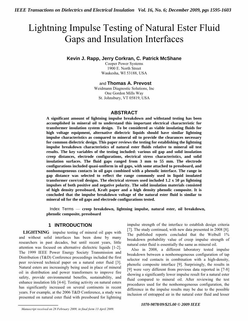
2.1.1 TYPE 1 SAMPLES Quasi-uniform field electrodes in oil gap as shown in
Figure 1. Electrode material is rectangular aluminum bar 3.05 mm × 7.85 mm containing 3 layers paper. The turn-to-turn paper thickness totaled 0.56 mm between the conductors. The sample dimensions are 381 mm long × 70 mm wide with 279 mm of parallel facing electrode surface. There are about 127 mm between the electrode face and the disc. Each electrode is held by a cam-lock inside a 102 mm dia. × 22.2 mm thick aluminum disc with a 5.56 mm radius. The leads terminate and are secured inside the disc, which is mounted to a maple wood fixture via a threaded epoxy rod. The maple wood fixture has slides that allow the electrodes to be positioned to the correct gap distance and locked. Gaps of 25 mm and 50 mm were set with a “go-no-go” gage, but the actual gap was measured with a calipers. The gaps did not include the thickness of the turn insulation on the conductors.
Figure 1. Type 1 electrodes used for 25 and 50 mm oil gaps.
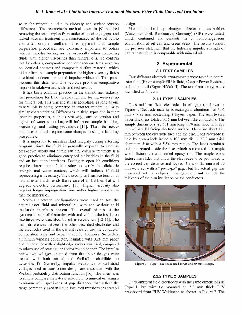
2.1.2 TYPE 2 SAMPLES Quasi-uniform field electrodes with the same dimensions as
Type 1, but wire tie mounted on 3.2 mm thick T-IV pressboard from EHV Weidmann as shown in Figure 2. The
K. J. Rapp et al.: Lightning Impulse Testing of Natural Ester Fluid Gaps and Insulation
rectangular pressboard was 508 mm L × 406 mm W with a 413 mm L × 102 mm W open window cut out 152 mm from either long edge. The electrode ends were placed inside stress reducing discs, which also terminated the leads. The electrode pairs were mounted on pressboards with a 12 mm gap maintained by three sets of secured spacers. One set in the middle and two sets on both ends. The spacers were used to maintain an accurate gap during sample processing and shipment, and were removed as the last step before impulse testing.
Figure 2. Type 2 electrodes used for 12 mm oil gap. Inset photo: stress reducing discs.
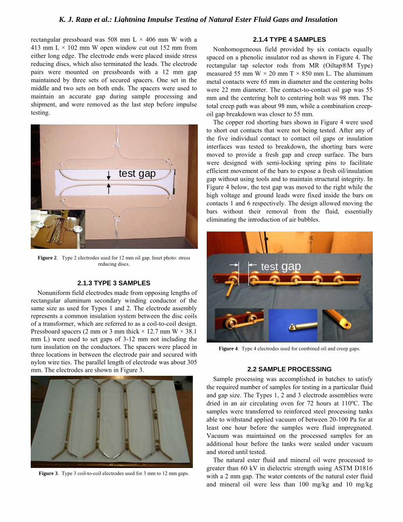
2.1.3 TYPE 3 SAMPLES Nonuniform field electrodes made from opposing lengths of
rectangular aluminum secondary winding conductor of the same size as used for Types 1 and 2. The electrode assembly represents a common insulation system between the disc coils of a transformer, which are referred to as a coil-to-coil design. Pressboard spacers (2 mm or 3 mm thick × 12.7 mm W × 38.1 mm L) were used to set gaps of 3-12 mm not including the turn insulation on the conductors. The spacers were placed in three locations in between the electrode pair and secured with nylon wire ties. The parallel length of electrode was about 305 mm. The electrodes are shown in Figure 3.
Figure 3. Type 3 coil-to-coil electrodes used for 3 mm to 12 mm gaps.
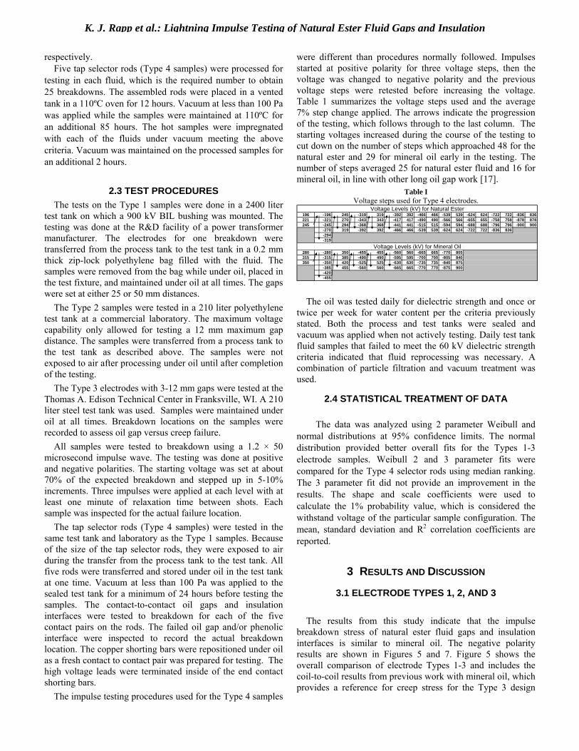
2.1.4 TYPE 4 SAMPLES Nonhomogeneous field provided by six contacts equally
spaced on a phenolic insulator rod as shown in Figure 4. The rectangular tap selector rods from MR (Oiltap®M Type) measured 55 mm W × 20 mm T × 850 mm L. The aluminum metal contacts were 65 mm in diameter and the centering bolts were 22 mm diameter. The contact-to-contact oil gap was 55 mm and the centering bolt to centering bolt was 98 mm. The total creep path was about 98 mm, while a combination creep-oil gap breakdown was closer to 55 mm.
The copper rod shorting bars shown in Figure 4 were used to short out contacts that were not being tested. After any of the five individual contact to contact oil gaps or insulation interfaces was tested to breakdown, the shorting bars were moved to provide a fresh gap and creep surface. The bars were designed with semi-locking spring pins to facilitate efficient movement of the bars to expose a fresh oil/insulation gap without using tools and to maintain structural integrity. In Figure 4 below, the test gap was moved to the right while the high voltage and ground leads were fixed inside the bars on contacts 1 and 6 respectively. The design allowed moving the bars without their removal from the fluid, essentially eliminating the introduction of air bubbles.
Figure 4. Type 4 electrodes used for combined oil and creep gaps.
2.2 SAMPLE PROCESSING Sample processing was accomplished in batches to satisfy
the required number of samples for testing in a particular fluid and gap size. The Types 1, 2 and 3 electrode assemblies were dried in an air circulating oven for 72 hours at 110ºC. The samples were transferred to reinforced steel processing tanks able to withstand applied vacuum of between 20-100 Pa for at least one hour before the samples were fluid impregnated. Vacuum was maintained on the processed samples for an additional hour before the tanks were sealed under vacuum and stored until tested.
The natural ester fluid and mineral oil were processed to greater than 60 kV in dielectric strength using ASTM D1816 with a 2 mm gap. The water contents of the natural ester fluid and mineral oil were less than 100 mg/kg and 10 mg/kg
test gap
test gap
test gaptest gap
K. J. Rapp et al.: Lightning Impulse Testing of Natural Ester Fluid Gaps and Insulation
respectively. Five tap selector rods (Type 4 samples) were processed for
testing in each fluid, which is the required number to obtain 25 breakdowns. The assembled rods were placed in a vented tank in a 110ºC oven for 12 hours. Vacuum at less than 100 Pa was applied while the samples were maintained at 110ºC for an additional 85 hours. The hot samples were impregnated with each of the fluids under vacuum meeting the above criteria. Vacuum was maintained on the processed samples for an additional 2 hours.
2.3 TEST PROCEDURES The tests on the Type 1 samples were done in a 2400 liter
test tank on which a 900 kV BIL bushing was mounted. The testing was done at the R&D facility of a power transformer manufacturer. The electrodes for one breakdown were transferred from the process tank to the test tank in a 0.2 mm thick zip-lock polyethylene bag filled with the fluid. The samples were removed from the bag while under oil, placed in the test fixture, and maintained under oil at all times. The gaps were set at either 25 or 50 mm distances.
The Type 2 samples were tested in a 210 liter polyethylene test tank at a commercial laboratory. The maximum voltage capability only allowed for testing a 12 mm maximum gap distance. The samples were transferred from a process tank to the test tank as described above. The samples were not exposed to air after processing under oil until after completion of the testing.
The Type 3 electrodes with 3-12 mm gaps were tested at the Thomas A. Edison Technical Center in Franksville, WI. A 210 liter steel test tank was used. Samples were maintained under oil at all times. Breakdown locations on the samples were recorded to assess oil gap versus creep failure.
All samples were tested to breakdown using a 1.2 × 50 microsecond impulse wave. The testing was done at positive and negative polarities. The starting voltage was set at about 70% of the expected breakdown and stepped up in 5-10% increments. Three impulses were applied at each level with at least one minute of relaxation time between shots. Each sample was inspected for the actual failure location.
The tap selector rods (Type 4 samples) were tested in the same test tank and laboratory as the Type 1 samples. Because of the size of the tap selector rods, they were exposed to air during the transfer from the process tank to the test tank. All five rods were transferred and stored under oil in the test tank at one time. Vacuum at less than 100 Pa was applied to the sealed test tank for a minimum of 24 hours before testing the samples. The contact-to-contact oil gaps and insulation interfaces were tested to breakdown for each of the five contact pairs on the rods. The failed oil gap and/or phenolic interface were inspected to record the actual breakdown location. The copper shorting bars were repositioned under oil as a fresh contact to contact pair was prepared for testing. The high voltage leads were terminated inside of the end contact shorting bars.
The impulse testing procedures used for the Type 4 samples
were different than procedures normally followed. Impulses started at positive polarity for three voltage steps, then the voltage was changed to negative polarity and the previous voltage steps were retested before increasing the voltage. Table 1 summarizes the voltage steps used and the average 7% step change applied. The arrows indicate the progression of the testing, which follows through to the last column. The starting voltages increased during the course of the testing to cut down on the number of steps which approached 48 for the natural ester and 29 for mineral oil early in the testing. The number of steps averaged 25 for natural ester fluid and 16 for mineral oil, in line with other long oil gap work [17].
Table I Voltage steps used for Type 4 electrodes.
Voltage Levels (kV) for Natural Ester196 -196 245 -319 319 -392 392 -466 466 -539 539 -624 624 -722 722 -836 836221 -221 270 -343 343 -417 417 -490 490 -566 566 -655 655 -758 758 -878 878245 -245 294 -368 368 -441 441 -515 515 -594 594 -688 688 -796 796 -900 900
-270 319 -392 392 -466 466 -539 539 -624 624 -722 722 -836 836-294-319
Voltage Levels (kV) for Mineral Oil280 -280 350 -455 455 -560 560 -665 665 -770 805315 -315 385 -490 490 -595 595 -700 700 -805 840350 -350 420 -525 525 -630 630 -735 735 -840 875
-385 455 -560 560 -665 665 -770 770 -875 900-420-455
The oil was tested daily for dielectric strength and once or
twice per week for water content per the criteria previously stated. Both the process and test tanks were sealed and vacuum was applied when not actively testing. Daily test tank fluid samples that failed to meet the 60 kV dielectric strength criteria indicated that fluid reprocessing was necessary. A combination of particle filtration and vacuum treatment was used.
2.4 STATISTICAL TREATMENT OF DATA
The data was analyzed using 2 parameter Weibull and normal distributions at 95% confidence limits. The normal distribution provided better overall fits for the Types 1-3 electrode samples. Weibull 2 and 3 parameter fits were compared for the Type 4 selector rods using median ranking. The 3 parameter fit did not provide an improvement in the results. The shape and scale coefficients were used to calculate the 1% probability value, which is considered the withstand voltage of the particular sample configuration. The mean, standard deviation and R2 correlation coefficients are reported.
3 RESULTS AND DISCUSSION
3.1 ELECTRODE TYPES 1, 2, AND 3
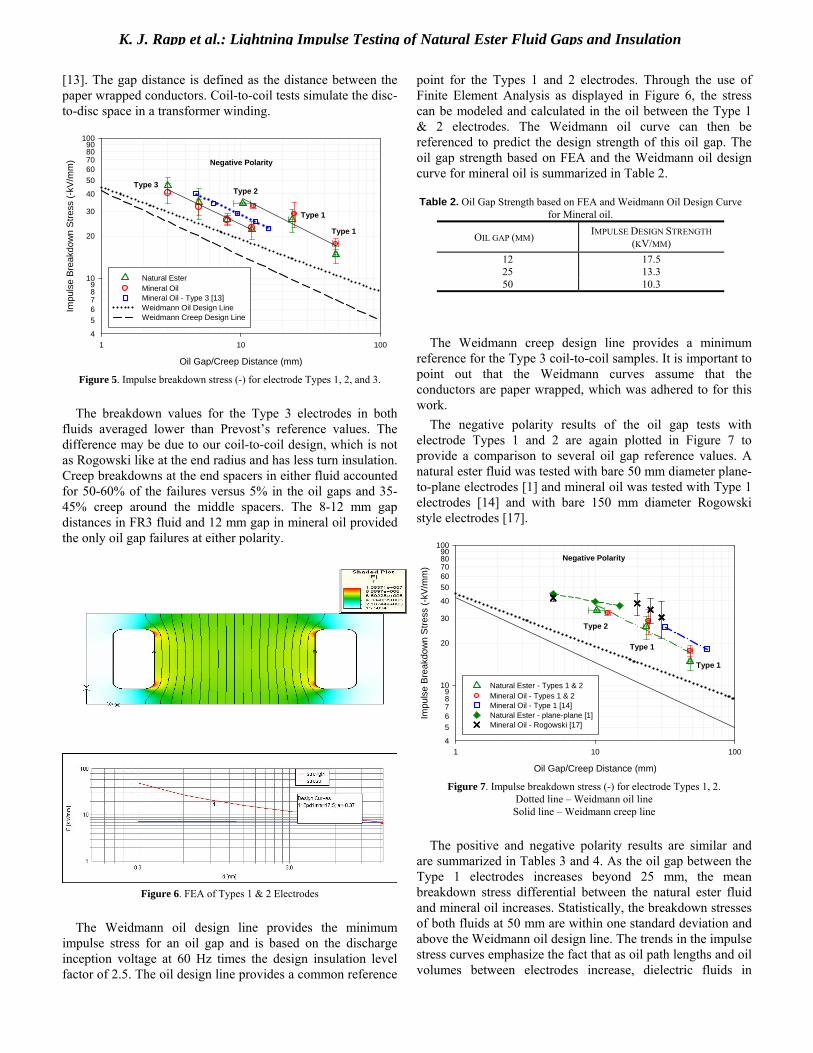
The results from this study indicate that the impulse breakdown stress of natural ester fluid gaps and insulation interfaces is similar to mineral oil. The negative polarity results are shown in Figures 5 and 7. Figure 5 shows the overall comparison of electrode Types 1-3 and includes the coil-to-coil results from previous work with mineral oil, which provides a reference for creep stress for the Type 3 design
K. J. Rapp et al.: Lightning Impulse Testing of Natural Ester Fluid Gaps and Insulation
[13]. The gap distance is defined as the distance between the paper wrapped conductors. Coil-to-coil tests simulate the disc-to-disc space in a transformer winding.
Oil Gap/Creep Distance (mm)
1 10 100
Impu
lse
Bre
akdo
wn
Stre
ss (-
kV/m
m)
4
56789
20
30
40
5060708090
10
100
Natural EsterMineral OilMineral Oil - Type 3 [13]Weidmann Oil Design LineWeidmann Creep Design Line
Negative Polarity
Type 3
Type 1
Type 2
Type 1
Figure 5. Impulse breakdown stress (-) for electrode Types 1, 2, and 3.
The breakdown values for the Type 3 electrodes in both
fluids averaged lower than Prevost’s reference values. The difference may be due to our coil-to-coil design, which is not as Rogowski like at the end radius and has less turn insulation. Creep breakdowns at the end spacers in either fluid accounted for 50-60% of the failures versus 5% in the oil gaps and 35-45% creep around the middle spacers. The 8-12 mm gap distances in FR3 fluid and 12 mm gap in mineral oil provided the only oil gap failures at either polarity.
Figure 6. FEA of Types 1 & 2 Electrodes
The Weidmann oil design line provides the minimum
impulse stress for an oil gap and is based on the discharge inception voltage at 60 Hz times the design insulation level factor of 2.5. The oil design line provides a common reference
point for the Types 1 and 2 electrodes. Through the use of Finite Element Analysis as displayed in Figure 6, the stress can be modeled and calculated in the oil between the Type 1 & 2 electrodes. The Weidmann oil curve can then be referenced to predict the design strength of this oil gap. The oil gap strength based on FEA and the Weidmann oil design curve for mineral oil is summarized in Table 2.
Table 2. Oil Gap Strength based on FEA and Weidmann Oil Design Curve for Mineral oil.
OIL GAP (MM) IMPULSE DESIGN STRENGTH (KV/MM)
The Weidmann creep design line provides a minimum
reference for the Type 3 coil-to-coil samples. It is important to point out that the Weidmann curves assume that the conductors are paper wrapped, which was adhered to for this work.
The negative polarity results of the oil gap tests with electrode Types 1 and 2 are again plotted in Figure 7 to provide a comparison to several oil gap reference values. A natural ester fluid was tested with bare 50 mm diameter plane-to-plane electrodes [1] and mineral oil was tested with Type 1 electrodes [14] and with bare 150 mm diameter Rogowski style electrodes [17].
Oil Gap/Creep Distance (mm)
1 10 100
Impu
lse
Bre
akdo
wn
Stre
ss (-
kV/m
m)
4
56789
20
30
40
5060708090
10
100
Natural Ester - Types 1 & 2Mineral Oil - Types 1 & 2Mineral Oil - Type 1 [14]Natural Ester - plane-plane [1]Mineral Oil - Rogowski [17]
Negative Polarity
Type 2
Type 1
Type 1
Figure 7. Impulse breakdown stress (-) for electrode Types 1, 2.
Dotted line – Weidmann oil line Solid line – Weidmann creep line
The positive and negative polarity results are similar and
are summarized in Tables 3 and 4. As the oil gap between the Type 1 electrodes increases beyond 25 mm, the mean breakdown stress differential between the natural ester fluid and mineral oil increases. Statistically, the breakdown stresses of both fluids at 50 mm are within one standard deviation and above the Weidmann oil design line. The trends in the impulse stress curves emphasize the fact that as oil path lengths and oil volumes between electrodes increase, dielectric fluids in
12 17.5 25 13.3 50 10.3

K. J. Rapp et al.: Lightning Impulse Testing of Natural Ester Fluid Gaps and Insulation
general become weaker. Thus, transformer designers use insulation barriers to break up oil gaps greater than 12-15 mm.
Prebreakdown phenomena, also called streamer formation, are a likely mechanism for impulse breakdown. Research at gaps up to 50 mm indicates that streamer inception and propagation are similar between natural esters and mineral oil [18-19]. In contrast, recent work with fast streamer formation and propagation in natural esters may be a factor for long oil distances out to 200 mm, which highlights the importance of adding insulation barriers to reduce large oil gaps [20].
The impulse breakdown results for electrode Types 1 and 2 at both polarities are summarized in Table 3. The results for the Type 3 electrodes are summarized in Table 4.
Table 3. Summary of Electrode Types 1 and 2 Impulse Breakdown Lightning Impulse - Negative Polarity
Electrode TypeOil Gap
FluidNatural Ester
Mineral Oil
Natural Ester
Mineral Oil
Natural Ester
Mineral Oil
Average oil gap (mm) 48.1 48.0 23.3 24.1 10.3 12.3
U50% (kV) 712 846 611 695 352 404Std Dev. (± kV) 97.8 79.4 116 139 8.3 13.9
s (%) 14 9.4 19 20 2.4 3.4
Lightning Impulse - Positive Polarity
Electrode TypeOil Gap
FluidNatural Ester
Mineral Oil
Natural Ester
Mineral Oil
Natural Ester
Mineral Oil
Average oil gap (mm) 50.4 48.7 24.5 24.0 11.3 12.0
U50% (kV) 722 856 630 690 388 387
Std Dev. (± kV) 131 102 74.1 103 20.7 16.5s (%) 18 12 12 15 5.3 4.3
Type 1 Type 1 Type 250 mm 25 mm 12 mm
Type 1 Type 1 Type 250 mm 25 mm 12 mm
Table 4. Summary of Electrode Type 3 Impulse Breakdown Lightning Impulse - Negative Polarity
Electrode TypeOil Gap
FluidNatural Ester
Mineral Oil
Natural Ester
Mineral Oil
Natural Ester
Mineral Oil
Natural Ester
Mineral Oil
U50% (kV) 139 122 175 156 211 209 266 275
Std Dev. (± kV) 18.5 20.3 44.5 21.0 21.0 16.9 38.8 17.3
s (%) 13 17 25 13 10 8.1 15 6.3
Lightning Impulse - Positive Polarity
Electrode TypeOil Gap
FluidNatural Ester
Mineral Oil
Natural Ester
Mineral Oil
Natural Ester
Mineral Oil
Natural Ester
Mineral Oil
U50% (kV) 132 129 160 140 210 199 274 265Std Dev. (± kV) 13.7 14.0 13.3 23.8 14.4 24.7 37.9 17.2
s (%) 10 11 8.3 17 6.9 12 14 6.5
3 mm 5 mm 8 mm
Type 3 Type 3 Type 33 mm 5 mm 8 mm
Type 312 mm
Type 312 mm
Type 3 Type 3 Type 3
3.2 ELECTRODE TYPE 4 – TAP SELECTOR RODS The impulse breakdown and calculated withstand results
from testing twenty five Type 4 gaps in each fluid shows that the natural ester fluid is comparable with mineral oil. The results provide good agreement with the creep breakdown and withstand values reported previously in [7-8], and the oil gap results of this study. The normal and Weibull probabilities of impulse breakdown are shown in Figures 8 and 9.
Breakdown Voltage (kV)
400 600 800 1000 1200
Impu
lse
Bre
akdo
wn
Pro
babi
lity
(%)
12
5
10
20
30
50
70
80
90
95
9899
Natural EsterMineral Oil
Figure 8. Normal distribution of Impulse breakdown probability - Type 4
gaps
Breakdown Voltage (kV)
300 400 500 600 700 800 900 1000
Bre
akdo
wn
Pro
babi
lity
%
1
2
5
10
20
30
50
70
90
99
Natural EsterMineral Oil
Figure 9. Weibull distribution of Impulse breakdown probability - Type 4
gaps.
The Type 4 sample failures were recorded as either oil gap or creep breakdowns. There was a difference between the fluids. In natural ester fluid, 64% of the gaps broke down in the fluid versus on the phenolic interface. In mineral oil, the split was 50:50. The breakdown results for just the oil gaps versus just the creep surfaces were about the same as the complete data set. The majority of the breakdowns in each fluid, about 75%, were of positive polarity. The total number of impulses applied to the Type 4 samples before failure averaged 125 in natural ester fluid compared to 80 in mineral oil. This difference may help explain the slight difference between the natural ester and mineral oil at the upper end of the breakdown probability curves in Figures 8 and 9. The results from data analysis using normal and Weibull distributions are summarized in Table 5.
K. J. Rapp et al.: Lightning Impulse Testing of Natural Ester Fluid Gaps and Insulation
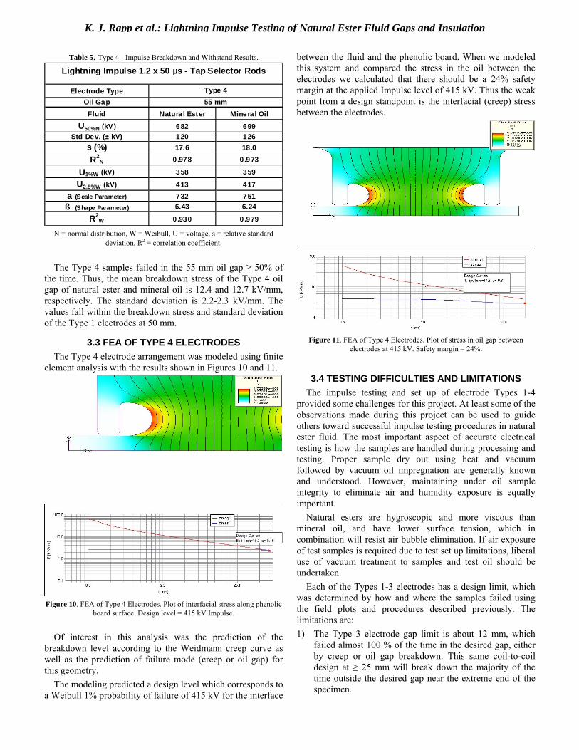
Table 5. Type 4 - Impulse Breakdown and Withstand Results. Lightning Impulse 1.2 x 50 µs - Tap Selector Rods
Electrode TypeOil GapFluid Natura l Ester Mineral Oil
U50%N (kV) 682 699Std Dev. (± kV) 120 126
s (%) 17.6 18.0
R2N 0.978 0.973
U1%W (kV) 358 359
U2.5%W (kV) 413 417a (Scale Parameter) 732 751ß (Shape Parameter) 6.43 6.24
R2W 0.930 0.979
Type 455 mm
N = normal distribution, W = Weibull, U = voltage, s = relative standard
deviation, R2 = correlation coefficient.
The Type 4 samples failed in the 55 mm oil gap ≥ 50% of the time. Thus, the mean breakdown stress of the Type 4 oil gap of natural ester and mineral oil is 12.4 and 12.7 kV/mm, respectively. The standard deviation is 2.2-2.3 kV/mm. The values fall within the breakdown stress and standard deviation of the Type 1 electrodes at 50 mm.
3.3 FEA OF TYPE 4 ELECTRODES The Type 4 electrode arrangement was modeled using finite
element analysis with the results shown in Figures 10 and 11.
Figure 10. FEA of Type 4 Electrodes. Plot of interfacial stress along phenolic
board surface. Design level = 415 kV Impulse.
Of interest in this analysis was the prediction of the breakdown level according to the Weidmann creep curve as well as the prediction of failure mode (creep or oil gap) for this geometry.
The modeling predicted a design level which corresponds to a Weibull 1% probability of failure of 415 kV for the interface
between the fluid and the phenolic board. When we modeled this system and compared the stress in the oil between the electrodes we calculated that there should be a 24% safety margin at the applied Impulse level of 415 kV. Thus the weak point from a design standpoint is the interfacial (creep) stress between the electrodes.
Figure 11. FEA of Type 4 Electrodes. Plot of stress in oil gap between
electrodes at 415 kV. Safety margin = 24%.
3.4 TESTING DIFFICULTIES AND LIMITATIONS The impulse testing and set up of electrode Types 1-4
provided some challenges for this project. At least some of the observations made during this project can be used to guide others toward successful impulse testing procedures in natural ester fluid. The most important aspect of accurate electrical testing is how the samples are handled during processing and testing. Proper sample dry out using heat and vacuum followed by vacuum oil impregnation are generally known and understood. However, maintaining under oil sample integrity to eliminate air and humidity exposure is equally important.
Natural esters are hygroscopic and more viscous than mineral oil, and have lower surface tension, which in combination will resist air bubble elimination. If air exposure of test samples is required due to test set up limitations, liberal use of vacuum treatment to samples and test oil should be undertaken.
Each of the Types 1-3 electrodes has a design limit, which was determined by how and where the samples failed using the field plots and procedures described previously. The limitations are: 1) The Type 3 electrode gap limit is about 12 mm, which
failed almost 100 % of the time in the desired gap, either by creep or oil gap breakdown. This same coil-to-coil design at ≥ 25 mm will break down the majority of the time outside the desired gap near the extreme end of the specimen.

K. J. Rapp et al.: Lightning Impulse Testing of Natural Ester Fluid Gaps and Insulation
2) The Type 2 samples were initially built to test the fluid with 12, 25, and 50 mm gaps. However, only the 12 mm samples would break down in the desired oil gap region. The ≥ 25 mm samples failed the majority of the time at the end radius via creep along the pressboard support. A significant number of failures initiated at or flashed over to the back side of the electrodes, usually near the nylon tie wrap.
3) Electrode sample connections can not be made with alligator clips/clamps, even at the smaller gaps. Lead connections should be terminated inside a stress reducing sphere or disc. Failure to adhere to the above will cause flash-over problems.
4) The Type 1 electrode design at a 50 mm gap is the limit for the rectangular conductor wire used. Some of the test samples failed outside the desired gap area either at the extreme radius or at the back side of the electrode. It is probable that a sharp point or burr on the electrode surface under the paper wrapping was the cause.
5) The shorting connections used for the Type 4 samples should allow for quick and easy change under oil. If under oil sample manipulations are not possible, vacuum treatment of the test tank containing the connected sample should be done.
4 CONCLUSIONS
The lightning impulse testing undertaken in this project shows that the lightning impulse breakdown/withstand of natural ester fluid are comparable to mineral oil.
Test arrangements yielded data to evaluate the lightning impulse strength of both oil gaps and interfacial creep. Oil gap test results from the Type 1 and Type 2 electrodes were comparable with industry design criteria. Limited sample size did not allow a reasonable calculation of withstand probability. Additional testing would allow 1% withstand probability to be calculated. The addition of pressboard spacers between the conductors lowered the average impulse breakdown strength in accordance with dielectric design theory. The creep strength of these spacers was comparable between mineral oil and natural ester and matched the industry design curve.
The test program of a nonhomogeneous arrangement of bare electrodes imbedded in phenolic insulation resulted in a suitable sample size to calculate low breakdown probability. The results of this test also supported the expected breakdown strength according to industry design curves which were established for mineral oil and demonstrated that there was essentially no difference in impulse withstand between mineral oil and natural ester fluid. The performance of the natural ester fluid tested should allow transformer manufacturers to use the same mineral oil impulse design rules for new transformers using the natural ester fluid.
While most previous results and those reported in this research show equivalent lightning impulse breakdown, some researchers showed a significant difference. Comparison of the testing methods indicated that handling and testing procedures may have caused air bubble entrapment in the
higher viscosity natural ester fluid. The results of this study confirmed that the use of vacuum after air exposure of the test specimens, improved test setup and fluid processing are important to obtain unbiased lightning impulse results of natural ester fluid.
The results also indicate that for field installed or retrofilled power transformers with natural ester fluid, the use of vacuum filling, maintaining reduced viscosity of the fluid through heating, and removal of particulates and dissolved gas are important to maintain the equivalent design level of lightning impulse withstand compared to mineral oil.
ACKNOWLEDGMENT The authors would like to acknowledge the work and
support of Shirish Mehta and Jeff Nemec of Waukesha Electric Systems, Michael Franchek and Jason Beaudoin of Weidmann Technical Services and Dennis Conway, John Luksich, Joel Holt, and Victor Murn, of Cooper Power Systems during the course of this work.
REFERENCES [1] R. Badent, Y. Julliard, K. Kist and A.J. Schwab, “Behaviour of Rape-
Seed-Oils under Impulse Voltages”, IEEE Conf. Electr. Insul. Dielectr. Phenomena (CEIDP), Austin, USA, pp. 638-641, 1999.
[2] R. Badent, K. Kist, B. Rüggemeir, W. Zierhut and A.J. Schwab, “Dielectric Characteristics of Rapeseed Oil”, IEEE Conf. Electr. Insul. Dielectr. Phenomena (CEIDP), Atlanta, USA, pp. 456-459, 1998.
[3] C.P. McShane, G.A. Gauger and J. Luksich, “Fire Resistant Natural Ester Dielectric Fluid and Novel Insulation System for Its Use”, IEEE/PES Transmission and Distribution Conf., New Orleans, LA, USA, pp. 890-894, 1999.
[4] C.P. McShane, “New Safety Dielectric Coolants for Distribution and Power Transformers”, IEEE Industry Applications Mag., Vol. 6, No. 3, pp. 24-31, 2000.
[5] C.P. McShane, “Vegetable Oil-Based Dielectric Coolants”, IEEE Industry Applications Mag., Vol. 8, No. 3, pp. 34-41, 2002.
[6] D. Martin, I. U. Khan, J. Dai and Z. D. Wang, “An overview of the suitability of vegetable oil dielectrics for use in large power transformers”, 5th Annual Euro TechCon Chester, UK, pp. 28-30, 2006.
[7] T.A. Prevost, “Dielectric Properties of Natural Esters and their Influence on Transformer Insulation System Design and Performance”, IEEE/PES Transmission and Distribution Conf., Dallas, TX, USA, Paper No. TD2005-000559, 2005/2006.
[8] T.A. Prevost, M. Franchek and K. Rapp, “Investigation of the Dielectric Design Criteria for Pressboard/Natural Ester Interfacial Stress”, 75th Intern. Conf. Doble Clients, Boston, MA, USA, Paper No. IM-3, 2008.
[9] S. Tenbohlen, M. Koch, D. Vukovic, A. Weinläder, J. Baum, J. Harthun, M. Schäfer, S. Barker, R. Frotscher, D. Dohnal and P. Dyer, “Application of Vegetable Oil-Based Insulating Fluids to Hermetically Sealed Power Transformers”, CIGRE Conf., Paper A2-102, 2008.
[10] J. Dai nd Z. D. Wang, “A Comparison of the Impregnation of Cellulose Insulation by Ester and Mineral Oil”, IEEE Trans. Dielectr. Electr. Insul., Vol. 15, pp. 374-381, 2008.
[11] IEEE Guide for Acceptance and Maintenance of Natural Ester Fluids in Transformers, IEEE Standard C57.147 – 2008, IEEE Power & Energy Society, New York, NY, 2008.
[12] T.H. Sie and O.F. Wohlfahrt, “Contribution to the Measurement of the Impulse Withstand Voltage of Oil-Paper-Insulation Systems”, IEEE Trans. Power Apparatus and Syst., Vol. 88, pp. 862-868, 1969.
[13] T. Prevost and M. Franchek, “Conductor Insulation Tests in Oil Aramid vs. Kraft,” IEEE Electr. Insul. Mag., Vol. 5, No. 4, pp. 10-14, 1989.
[14] M.U. Anker, “Effect of Test Geometry, Permittivity Matching and Metal Particles on the Flashover Voltage of Oil/Solid Interfaces”, IEEE Trans. Power Apparatus and Syst., Vol. 102, pp. 3796-3802, 1983.

K. J. Rapp et al.: Lightning Impulse Testing of Natural Ester Fluid Gaps and Insulation
[15] L. Lundgaard, K. Herstad, M.U. Anker and J. Sletbak, “Flashover Along Solid Surfaces Parallel to the Electric Field in Liquid Insulation at 50 Hz”, CIGRE 1986, Paris,France, Paper 15 08.
[16] J.K. Nelson, “An Assessment of the Physical Basis for the Application
of Design Criteria for Dielectric Structures”, IEEE Trans. Electr. Insul., Vol. 24, pp. 835-847, 1989.
[17] W. Lick and M. Muhr, “Strength Investigations on Long Oil Gaps”, IEEE 14th Intern. Conf. Dielectr. Liquids (ICDL), Graz, Austria, pp. 228-230, 2002.
[18] R. Badent, M. Hemmer, U. Konekamp, Y. Julliard and A.J. Schwab, “Streamer Inception Field Strength in Rapeseed Oils”, IEEE Conf. Electr. Insul. Dielectr. Phenomena (CEIDP), Victoria, Canada, Session 3B-4, pp. 272-275, 2000.
[19] M. Hemmer, Y. Julliard, R. Badent and A.J. Schwab, “Streamer Inception and Propagation in Rapeseed Oils and Mineral Oils”, IEEE Conf. Electr. Insul. Dielectr. Phenomena (CEIDP), Kitchener, Canada, Session 7C-5, pp. 548-551, 2001.
[20] C. Tran Duy, O. Lesaint, N. Bonifaci, A. Denat and Y. Bertrand, “High Voltage Breakdown and Pre-breakdown Properties in Rape-seed Insulating Oil,” IEEE Conf. Electr. Insul. Dielectr. Phenomena (CEIDP), Vancouver, BC Canada, Session 7-2, pp. 623-626, 2007.
Kevin J. Rapp received a B.S. degree in chemistry from the University of Wisconsin, Parkside, WI USA. He was a Laboratory Associate and Chemist at the Thomas A. Edison Technical Center, Franksville, WI from 1976 to 2004. He was involved in dielectric fluids and insulating materials research, and is one of the inventors of the natural ester fluid, Envirotemp® FR3® fluid. He is currently a Senior Project Engineer in the Dielectric Fluids Group at Cooper Power Systems, Waukesha, WI USA. Mr. Rapp is a member of the ASTM D27 Committee on Electrical Insulating Liquids and Gases where he
chairs a task group on the oxidation stability of natural ester fluids. He is also a member of ACS, AOCS, CIGRE and IEC, where he is involved in developing an IEC standard for natural ester fluids.
Jerry L. Corkran (M’77–SM’06). He obtained the BSEE (1964) and MSEE (1965) degrees from the University of Missouri, Columbia, Missouri, USA. He is a registered Professional Engineer in the State of Wisconsin. He was a development Engineer from 1965 to 1971 for Allis Chalmers, from 1971-79 he was a Design Engineer for the RTE-ASEA in Waukesha, WI. He joined Cooper Power Systems (RTE) in 1979 where he is currently a Staff Engineer. Mr. Corkran is an active member of the IEEE Transformer Committee. He is one of the inventors of the natural ester fluid, Envirotemp® FR3® fluid.
C. Patrick McShane (M’87-SM’07) received a BSEE degree from Marquette University in 1970 and his MSEM from the Milwaukee School of Engineering in 1998. He is a Professional Engineer registered in the State of Wisconsin. He was a consultant on the design and operation for a Brazilian Rural Electrification program for several years. Since 1984, he has been involved with safety and environmentally preferred
dielectric coolants and their application in electrical distribution and power equipment. Currently his position at CPS is Global Technology Manager – Dielectric Fluids. He is the principal inventor of a seed oil-based dielectric coolant filled transformer. The invention was a Plant Engineering magazine 1998 Product of the Year Winner. Mr. McShane is an internationally recognized expert in transformer fire and environmental safety, and codes and standards development and compliance. Professional memberships include IEEE –Senior Member, National Fire Protection Association, and AOCS. He was the chairman of the IEEE Std. C57.147 “Standard Guide for Acceptance and Maintenance of Natural Esters in Transformers Thomas A. Prevost (M’85-SM’08) is the Vice President Technology at Weidmann Diagnostic Solutions Inc. He works out of the office in St. Johnsbury, Vermont, USA. He has been employed with Weidmann Electrical Technology since 1985. He received the BSEE degree from Virginia Polytechnic Institute. He joined the Weidmann Diagnostic Solutions team in
2006. Previously he was the Vice President of Technical Service at EHV-Weidmann, a manufacturer of electrical insulation materials for the transformer industry. Prior to that he worked at Tampa Electric Company as an engineer in distribution and production. Thomas is an active member of IEEE. He is currently the Chair of the IEEE PES Transformers Committee. He is the Vice-Chair of the IEEE Standards Association-Standards Board and Chair of the New Standards Committee (Nescom). Thomas is also active in ASTM committee D27 on Insulating Fluids and IEC
committee TC 10 on Insulating Fluids. Mr. Prevost has written many technical papers on the subject of electrical insulation materials and transformer diagnostics.