light-narrowed optically pumped m_{x} magnetometer with a miniaturized cs cell
TRANSCRIPT

PHYSICAL REVIEW A 84, 043416 (2011)
Light-narrowed optically pumped Mx magnetometer with a miniaturized Cs cell
T. Scholtes,* V. Schultze, R. IJsselsteijn, S. Woetzel, and H.-G. MeyerInstitute of Photonic Technology, Albert-Einstein-Strasse 9, D-07745 Jena, Germany
(Received 15 July 2011; published 12 October 2011)
We demonstrate a way of operating an optically pumped magnetometer with miniaturized cesium cell using thelight-narrowing effect. The magnetometer setup shows improvement of shot-noise-limited sensitivity (42 fT/
√Hz
in a cell of only 9.3 mm3 volume) due to the suppression of spin-exchange relaxation to a large extent and theuse of a strikingly increased fraction of alkali-metal atoms for signal generation, working even in μT magneticfields, by using only a single high-intensity laser beam both for pumping and probing of atomic spins.
DOI: 10.1103/PhysRevA.84.043416 PACS number(s): 32.10.Dk, 07.55.Ge, 32.10.Fn
I. INTRODUCTION
Optically pumped magnetometers measure the strengthof external magnetic fields by monitoring the precession(Larmor) frequency ωL of atomic spins of alkali metal vaporenclosed in gas cells [1,2]. By the use of the double radio-optical resonance method [3,4], where the resonance of theprecessing spins with an additional oscillating magnetic fieldis monitored by optical means, very high sensitivities areachieved. The sensitivity of an optically pumped magnetome-ter is given by
Bn = 1
γ
√R
nV, (1)
where γ denotes the gyromagnetic ratio of the alkali metalin use (Cs: 3.5 Hz
nT ), n the temperature-dependent alkali vapordensity, and V the cell volume. R is the relaxation rate whichdescribes how fast atomic coherence is destroyed by relaxationprocesses inside the cell. Although Eq. (1) suggests large cellvolume to achieve best sensitivity, we use miniaturized cavitiesin microfabricated cell arrays as the central sensor element [5],technologically based on recent developments of miniaturizedatomic clocks and magnetometers at the National Institute ofStandards and Technology (NIST) [6,7]. Several argumentslike future batch production with reproducible parameters,the possibility of small spacing of (possibly connected)neighboring cells (to form well-matched gradiometers or tointroduce reference cells for noise reduction [8]), or keepingexternal magnetic field gradients over the cell volume andbetween two cells as small as possible count for that strategy.According to Eq. (1) the way to improve sensitivity thenis to raise n by increasing the cell temperature, until thegrowing coherence relaxation rate R sets a limit to furtherheating. So the sensitivity of the magnetometer is eventuallydetermined by how well atomic coherence is conserved. Withproper cell design, where wall relaxation is made negligible byantirelaxation wall coating [9–11] or hindering the movementof the alkali-metal atoms to the walls by buffer gas [12,13],demolition of the coherence will finally be dominated bycollisions of alkali-metal atoms with each other. The relaxationrate due to these collisions is given by
R = nσ v (2)
with v denoting the average thermal velocity of alkali-metalatoms and σ the cross section of the respective process. Inconventional-mode operation now the spin-exchange relax-ation is the limiting mechanism, because for all alkali metalsspin-exchange cross sections σSE (Cs: 2 · 10−14 cm2) are atleast two orders of magnitude larger than those for spin-destruction σSD. However, as was demonstrated a long timeago and explained shortly after [14,15], suppressing relaxationdue to spin exchange is possible. This narrowing effect showsup at high atomic vapor densities in very low magnetic fields,when the spin-exchange collision rate is much higher thanthe Larmor precession frequency (RSE � ωL). Successfulapplication in magnetometry was demonstrated in recentyears [16,17]. However, this so-called SERF (spin-exchange-relaxation-free) regime is inherently limited to operation nearzero-magnetic field.
Here we show a setup with the possibility of spin-exchangerelaxation suppression, which works in a magnetic field in theμT range and uses a single beam for pumping and probing.The resulting improvement of sensitivity is explained by thephenomenon of light narrowing [18] and the increased celltransparency due to pumping of a large fraction of atoms intoa stretched state.
II. EXPERIMENTAL SETUP
The experimental setup used is sketched in Fig. 1. Adistributed feedback (DFB) laser in combination with a taperedamplifier provides a narrow-band (�ν < 5 MHz) laser beamthat can be automatically tuned around the Cs D1 line(λ = 894.6 nm) and varied in intensity. The highly circularlypolarized beam (ellipticity >0.99)1 reaches intensities up to1.5 mW
mm2 in front of the fully illuminated window of the Cscell, whose temperature is set by off-resonant heating laserradiation (λ = 808 nm), fiber-coupled directly on the cellarray’s Si wafer parts. Inside the shielding barrel (shieldingfactor ≈103) a Helmholtz coil system supplies a homogeneousstatic magnetic field B0 = 5 μT oriented at 45◦ with respectto the laser beam direction for Mx operation [19,20]. Fordriving the Zeeman transitions another pair of Helmholtz coilssupplies the radio frequency (rf) magnetic field B1, which alsodrives the lock-in demodulation. The B1 field is oriented inlaser beam direction to keep the system’s axial symmetry [2].
1Here ellipticity means the minor-to-major axis ratio of thepolarization ellipse.
043416-11050-2947/2011/84(4)/043416(6) ©2011 American Physical Society

T. SCHOLTES et al. PHYSICAL REVIEW A 84, 043416 (2011)
oscillator
µ-metal shielding barrel
λ/4-plate U I
photo diode
static fieldcoils
pair of rotatablelinear polarizers
rf coils
Pip Pqu
cesium cell in Si wafer
transimpedanceamplifier
spectral filter plate
tapered amplifier
heating laser
linear polarizer
multimodeoptical fibers
B0
B1
lock-in
pump laser
FIG. 1. Scheme of the experimental setup. We use a thin Cs cell(4.5 × 4.5 × 0.5 mm3) of a microfabricated array [4].
Cell-transmitting laser intensity is detected by a photo diode.The heating laser radiation is blocked by a spectral filterplate. The actual shot-noise-limited sensitivity of the sensoris determined automatically according to
Bsn = G
γ
√2eIdc
dPqu/dν. (3)
The steepness dPqu/dν of the lock-in’s quadrature componentPqu is extracted at the center of the resonance line, Idc
denotes the corresponding photo current measured by thephoto detector, G is the transimpedance amplifier’s gain factor.
III. EXPERIMENTAL RESULTS
All measurements shown here were carried out in a 5 μTstatic magnetic field and using a cell with approximately170 mbar nitrogen buffer gas pressure, filled during fabrication[5], to reduce the alkali metal’s wall collision rate andfor effective quenching of excited alkali-metal atoms. Thisquenching mechanism prevents radiation trapping [21] andyields an equally probable repopulation of the ground statesublevels [22]. The chosen buffer gas pressure results in aD1 line absorption spectrum of the Cs cell as shown inFig. 2 (black line). Hyperfine splitting of the excited stateis unresolved owing to homogenous buffer gas pressurebroadening, the ground state hyperfine structure F = 7
2 ± 12
is partially resolved. Pumping with a narrow-band laser onthat cell absorption profile leads to simultaneous excitationof all four hyperfine D1 transitions, but the relative pumpingstrength on the ground state hyperfine levels can be varied bytuning the laser frequency.
Figure 2 shows the surprising observation that the measuredshot-noise-limited sensitivity can be improved by at least oneorder of magnitude when tuning the pumping laser frequencyfrom F = 4 to F = 3 when raising the laser intensity at thesame time. By further optimizing cell temperature, laser powerand rf field strength we finally achieved Bsn = 42 fT/
√Hz in
this configuration. This is an improvement in sensitivity bya factor of 40 compared to the conventional spin-exchangebroadened operation mode using the same cell. Table I summa-rizes the shot-noise-limited sensitivity optimizing operationaland measured Bsn determining parameters in both regimes.
FIG. 2. Measured cell absorption profile at 120 ◦C with partiallyresolved ground state hyperfine structure (black line), shot-noise-limited sensitivity in conventional operation modus (open circles)and light-narrowed operation (filled triangles). After optimizationof all parameters a sensitivity of 42 fT/
√Hz is achieved in the
light-narrowed mode (black star).
Here one has to note, that approaching shot-noise-limitedsensitivity requires sophisticated electronics, detecting verytiny AC signals on top of a large DC current. The givenshot-noise-limited field sensitivities correspond to changesin Larmor frequency of about 150 μHz and 5.3 mHz to bedetected in 1 Hz bandwidth for the light-narrowed (LN) andconventional mode, respectively. This corresponds to 32 pA(7 pA) change on top of 3.7 mA (0.15 mA) direct photo currentfor the two modes. This ratio of 10−8 (5 · 10−8) is at the limit ofwhat state-of-the-art electronics can achieve, but comparisonof the two regimes shows that only slightly more demandingelectronics are required in the LN mode. The transimpedanceamplifier we use (Femto DLCPA-200) exhibits a noise floor of20 pA/
√Hz (2.3 pA/
√Hz) when accepting a maximal input
current of 10 mA (1 mA). The used infrared photo diodefeatures a current noise far below the signals to detect. So,for the measurement shown here, the sensor electronics do notimpair the achieved results. However, for a further increase in
TABLE I. Comparision of shot-noise-limited sensitivity opti-mizing operational and measured Bsn determining parameters inconventional and light-narrowed operation mode according to Eq. (3).The steepness is given in units of direct photo current taking thetransimpedance amplifier’s gain factor G into account.
Conventional Parameter Light-narrowed
100 ◦C cell temperature 135 ◦C0.5 mW laser power 31 mW450 nT rf field amplitude rms 680 nT
6.4 μA Pqu amplitude 590 μA9.7 kHz Pqu width 5.0 kHz−1.3 μA/kHz dPqu/dν −230 μA/kHz0.15 mA Idc 3.7 mA1.5 pT/
√Hz Bsn 42 fT/
√Hz
043416-2

LIGHT-NARROWED OPTICALLY PUMPED Mx . . . PHYSICAL REVIEW A 84, 043416 (2011)
FIG. 3. Cell absorption curve as addition of the four buffer-gasbroadened Cs D1 hyperfine transitions fitted to the experimentallydetermined absorption profile of Fig. 2, using Lorentz profiles dueto the dominant buffer-gas broadening. Tuning the narrow-bandlaser from F = 4 (conventional mode) to F = 3 (LN mode) isaccompanied by changing the relative pumping ratio (F = 3 : F = 4)approximately from 1:5 to 9:1.
sensitivity one will also have to meet the technical challengeof building the adequate sensor electronics.
IV. DISCUSSION
How can the drastic improvement in magnetic field sensitiv-ity be explained? The answer is based on the different pumpingrates of the four buffer-gas broadened hyperfine transitionsshown in Fig. 3 and the resulting population distribution of theCs ground states shown in Fig. 4.
The conventional spin-exchange broadened Mx mode ofmagnetometer operation [Fig. 4(a)] uses resonant pumpingof the F = 4 D1 transitions by circularly polarized light. Theonly ground state sublevel that does not couple to σ+ pumpinglight is |F,mF 〉 = |4,4〉, so atoms get accumulated in this darkstate, where magnetic resonance is now detected when theB1 field repumping frequency equals the Larmor precessionfrequency of the spins. The ground state hyperfine transitionsfrom F = 3 are detuned from the narrow-band laser radiationof modest intensity, thus barely pumped corresponding to thesmall overlap of the F = 3 absorption profiles with the laserline (see Fig. 3). So, due to nitrogen quenching of the excitedstate, population from F = 4 is eventually transferred toF = 3, getting lost for magnetic resonance signal generation.Trapping of atoms in this lower ground state leads not only to adecreased magnetometer signal, population in F = 3 is furthercausing spin-exchange relaxation, thus limiting the magneticfield sensitivity.
The new LN mode of magnetometer operation uses thelight-narrowing effect, first described by Appelt et al. [18].The laser is tuned to the F = 3 transitions. Due to strongpumping, this hyperfine level, lacking dark sublevels, nowis completely depleted. At the same time, because of thesmall overlap of the F = 4 absorption profiles with the laser
FIG. 4. Pumping scheme and calculated populations (in percent)of the Cs ground state in (a) conventional-mode operation (pumpingon F = 4) and (b) in LN configuration (pumping on F = 3 with50-fold overall pumping rate). Laser pumping excitation is sketchedby black arrows, whose thicknesses indicate pumping strength. Thesteady-state solutions of the population rate equations for all 16ground state sublevels, given by Lang et al. [22] are used. This modelassumes depopulation pumping mechanism (quenching de-excitationequally probable to all ground state sublevels). It was extended toinclude a fixed relative pumping ratio between the hyperfine groundstate level transitions determined by the overlap of the partiallyresolved ground state absorption profile at the actual laser pumpingfrequency (as depicted in Fig. 3). Perfectly circularly polarized light isassumed and effects of repumping by B1 as well as the 45◦ orientationof B0 in the Mx regime are not included.
line (Fig. 3) this hyperfine transition, where the magneticresonance is detected, is modestly pumped and thus notaffected by extensive power-broadening. The pump rate onF = 3 has to be much larger than the spin-exchange rate thattends to redistribute ground state population toward thermalequilibrium. In the result, nearly all atoms are transferred toF = 4 and a very large fraction of them populates the magnetic
043416-3
T. SCHOLTES et al. PHYSICAL REVIEW A 84, 043416 (2011)
sublevel with highest spin angular momentum |4,4〉, thestretched state [Fig. 4(b)]. Spin-conserving collisions betweenstretched atoms cannot redistribute them in other ground statesublevels, especially not into lower counter-rotating levels, sothe repopulation of F = 3 is further suppressed and relaxationdue to spin exchange is diminished [23]. Additionally, atomsin the stretched state are transparent to the laser light,leading to an increased penetration depth of the light intothe cell compared to conventional mode operation at low laserintensities [24].
The nonzero angle between static magnetic field andcircular polarized laser light direction due to Mx modeoperation leads to precession of F = 4 atoms, spreading theminto the upper hyperfine states’ magnetic sublevels to somedegree [25]. These nonstretched atoms can get into F = 3by spin-exchange collisions, but are immediately removed bystrong pumping on that ground state hyperfine level.
So, due to the high pumping rate on F = 3 compared tothe spin exchange rate, a very large fraction of atoms staysstretched and the lower hyperfine state F = 3 is kept depleted.Even though the concentration of atoms into the stretchedstate is limited due to the 45◦ B0 field orientation in the Mx
modus (what is not yet included in the model shown in Fig. 4),we can improve the diminished stretched-state spin-exchangerelaxation suppression by the high pumping rate on F = 3,with this explaining the observed narrowing of the magneticresonance width in this regime.
The increased cell transparency and resonance narrowingallows to raise the cell temperature, thereby increasing thesensing atom number and the magnetometer signal with it toa large extent (cf. Table I), until increasing absorption of laserlight limits further heating. Additionally, the magnetometersignal in the LN mode is drastically increased, because almostall atoms are involved in the dark-state repumping cycle. Thisbeneficial effect arises from avoiding trapped atoms in F = 3and was previously exploited in vacuum cells using a secondrepumping laser resonant on F = 3. Thereby an increase inmagnetometer signal strength by a factor of 3 was achievedby Groeger et al. [26]. In contrast to this configuration, in
our case due to favorable pressure broadening one well-tunedsingle laser can act as repumper and we simultaneously benefitfrom the described LN mechanism using high laser intensitywith a buffer gas cell.
Even though spin-exchange relaxation is eliminated tosome extent (cf. the Pqu resonance line widths of the con-ventional and the LN regime in Table I), we do not work inthe SERF regime when regarding it in its narrow sense asused in [16,17]. Comparing the spin-exchange rate (calculatedaccording to Eq. (2) using the actual cell temperature)in the presented LN configuration RSE ≈ 60 kHz with theLarmor precession frequency in 5 μT static magnetic field(17.5 kHz) one can infer that SERF condition (RSE � ωL) isnot sufficiently satisfied. This is confirmed by the behaviorof the gyromagnetic ratio γ . In contrast to the SERF regime,where it gets dependent on magnetic field strength [15,27],in our LN operational mode γ stays constant for all usedmagnetic field strengths in the μT range. In our case keepingF = 3 depleted leads to conservation of coherent precessionformed by atoms in F = 4 (in other words the atoms’ effectiveduration of stay in F = 3 is very short compared to that inF = 4). For that reason the magnetometer can even work inthe geomagnetic field range where RSE ≈ ωL.
How can the presented results with the LN magnetometerbe valuated in comparison to fundamental limits and otheroptically pumped magnetometer operation modes? Pluggingthe saturated vapor density n at given cell temperature andthe measured resonance width R (Pqu width in Table I) intoEq. (1), the spin-projection-noise limit is calculated as Bn =80 fT/
√Hz in the conventional spin-exchange broadened
operation mode and Bn = 20 fT/√
Hz in the LN regime.So, while in this regime the measured shot-noise-limitedsensitivity approaches the fundamental limit by a factor of two,the conventional mode Bsn measurement is almost a factor of20 worse than Bn. This finding is in accordance with the workdone by Smullin et al. [28], which shows the possibility ofimproving the magnetometer sensitivity by LN if the sensoris limited by photon shot noise rather than operated near thefundamental spin-projection-noise limit.
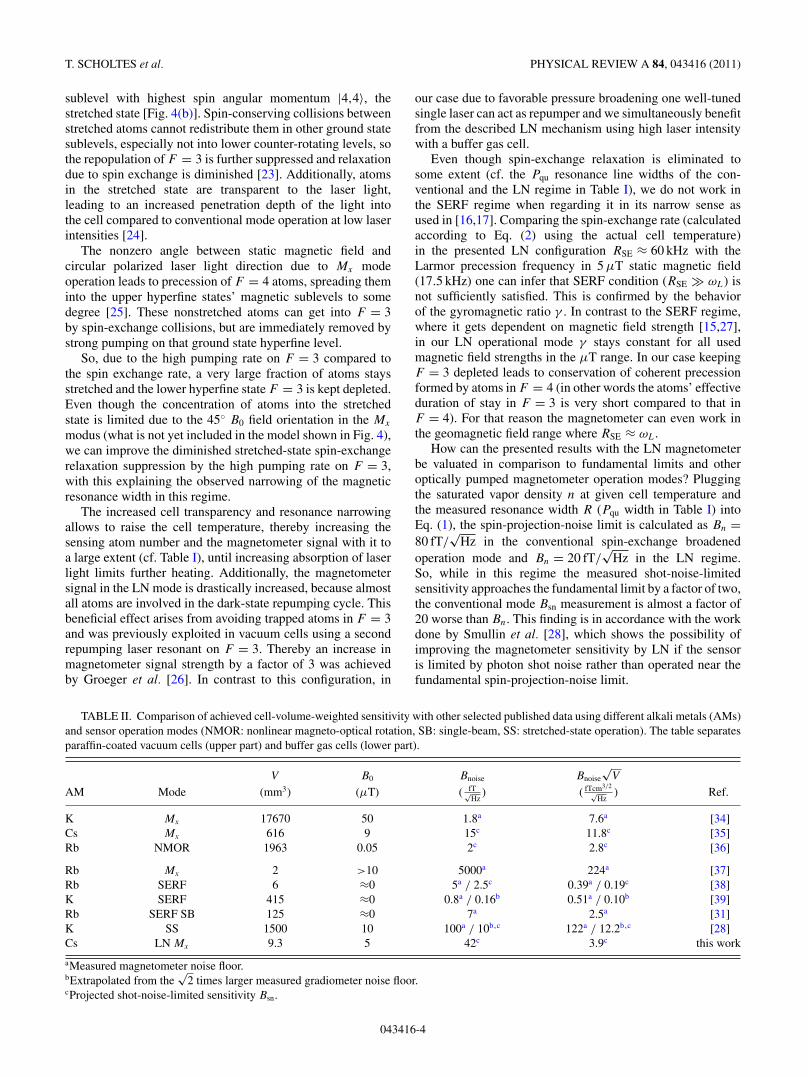
TABLE II. Comparison of achieved cell-volume-weighted sensitivity with other selected published data using different alkali metals (AMs)and sensor operation modes (NMOR: nonlinear magneto-optical rotation, SB: single-beam, SS: stretched-state operation). The table separatesparaffin-coated vacuum cells (upper part) and buffer gas cells (lower part).
V B0 Bnoise Bnoise
√V
AM Mode (mm3) (μT) ( fT√Hz
) ( fTcm3/2√Hz
) Ref.
K Mx 17670 50 1.8a 7.6a [34]Cs Mx 616 9 15c 11.8c [35]Rb NMOR 1963 0.05 2c 2.8c [36]
Rb Mx 2 >10 5000a 224a [37]Rb SERF 6 ≈0 5a / 2.5c 0.39a / 0.19c [38]K SERF 415 ≈0 0.8a / 0.16b 0.51a / 0.10b [39]Rb SERF SB 125 ≈0 7a 2.5a [31]K SS 1500 10 100a / 10b,c 122a / 12.2b,c [28]Cs LN Mx 9.3 5 42c 3.9c this work
aMeasured magnetometer noise floor.bExtrapolated from the
√2 times larger measured gradiometer noise floor.
cProjected shot-noise-limited sensitivity Bsn.
043416-4

LIGHT-NARROWED OPTICALLY PUMPED Mx . . . PHYSICAL REVIEW A 84, 043416 (2011)
A scheme of magnetometer operation using only a singlehigh-intensity laser beam detuned from the detected magneticresonance was shown recently using linearly polarized light[29], thereby not suppressing spin-exchange relaxation, butvery likely being not affected by Zeeman light shift. A realmagnetometer operation is not shown yet, however. The im-plementation of the light-narrowing effect in magnetometersby use of a fully stretched state (for rf as well as staticmagnetic fields) was published recently [28,30]. There, incontrast to our setup, the magnetometers are operated withbroad-band pumping and probing with an additional laserbeam. A complete single-beam SERF magnetometer workingwith off-resonant elliptically polarized light was presentedrecently, overcoming the need of two crossed laser beams forSERF operation by then [31].
In order to judge the actual development state more indetail, in Table II the (to our knowledge) best magnetometersin various operation modes are collected with their sensitivitiesas given by the authors, either in the shot-noise limit Bsn orobtained from magnetometer or gradiometer noise floors. Tocompare setups with different cell volumes V , the magneticfield sensitivity is weighted by
√V [cf. Eq. (1)]. Looking at
the figure of merit Bnoise
√V it shows up, that in near-zero
magnetic field the best values can be achieved with theSERF magnetometers. In the μT range, however, the LNmagnetometer presented in this paper already shows the bestperformance. In future work this potential has to be proven bydirectly measured (gradiometric) noise floors.
Further investigations will explore the relationship betweenoperation parameters on the one hand and achievable sensitiv-ity and allowed B0 field range on the other hand in more detail.With buffer gas type and pressure, optical pumping strengthand wavelength, as well as the use of thicker cells variousoperation parameters are at hand. These future investigationsalso have to face the problem of Zeeman light shift, resultingfrom the strong optical pumping. Because it depends on the
detuning from the magnetic transition in a dispersiveLorentzian shape [32,33], in our LN configuration this effectwill become remarkable. Consequently, without additionalefforts, at the present state the sensor operation wouldbe restricted to stationary magnetic fields. Removing theorientation dependence of measurement induced by the lightshift phenomenon using an additional offset static magneticfield is possible in principle [31] but waits for an experimentalstudy. Ways to suppress or even eliminate additional noisecontribution emerging from the light-shift coupling of laserintensity fluctuations directly to Larmor frequency fluctuationsare subjects of further investigations starting with a gradiomet-ric sensor design. The gradiometer or reference cell approachis also expected to get rid of the other common magnetometernoise sources and to bring the signal noise floor close to theshot-noise limit [8].
V. CONCLUSION
In summary, operation of an optically pumped magne-tometer with a miniaturized Cs cell using light narrowing byspectrally selective high-intensity pumping was demonstratedin single laser beam configuration. In doing so, spin-exchangerelaxation suppression and involving a considerably higherfraction of atoms in signal generation leads to an improvementof the shot-noise-limited sensitivity by a factor of 40 comparedto the conventional operation mode using the same cell. Incontrast to SERF operation, the LN modus also works in theμT magnetic field range.
ACKNOWLEDGMENTS
This work was partially supported by the State of Thuringia,Germany (B714-10043) under participation of the EuropeanUnion within the European Regional Development Fund.
[1] D. Budker and M. V. Romalis, Nature Phys. 3, 227 (2007).[2] E. B. Aleksandrov and A. K. Vershovskii, Phys. Usp. 52, 573
(2009).[3] W. E. Bell and A. L. Bloom, Phys. Rev. 107, 1559 (1957).[4] A. Weis and R. Wynands, Opt. Lasers Eng. 43, 387 (2005).[5] S. Woetzel, V. Schultze, R. IJsselsteijn, T. Schulz, S. Anders, R.
Stolz, and H.-G. Meyer, Rev. Sci. Instrum. 82, 033111 (2011).[6] P. D. D. Schwindt, S. Knappe, V. Shah, L. Hollberg, J. Kitching,
L.-A. Liew, and J. Moreland, Appl. Phys. Lett. 85, 6409 (2004).[7] S. Knappe, P. D. D. Schwindt, V. Gerginov, V. Shah, L. Liew, J.
Moreland, H. G. Robinson, L. Hollberg, and J. Kitching, J. Opt.A: Pure Appl. Opt. 8, S318 (2006).
[8] V. Schultze, R. IJsselsteijn, and H.-G. Meyer, Appl. Phys. B 100,717 (2010).
[9] D. Budker, L. Hollberg, D. F. Kimball, J. Kitching, S. Pustelny,and V. V. Yashchuk, Phys. Rev. A 71, 012903 (2005).
[10] S. J. Seltzer and M. V. Romalis, J. Appl. Phys. 106, 114905(2009).
[11] M. V. Balabas, T. Karaulanov, M. P. Ledbetter, and D. Budker,Phys. Rev. Lett. 105, 070801 (2010).
[12] W. Happer, Rev. Mod. Phys. 44, 169 (1972).[13] D. Giel, G. Hinz, D. Nettels, and A. Weis, Opt. Express 6, 251
(2000).[14] W. Happer and H. Tang, Phys. Rev. Lett. 31, 273 (1973).[15] W. Happer and A. C. Tam, Phys. Rev. A 16, 1877 (1977).[16] J. C. Allred, R. N. Lyman, T. W. Kornack, and M. V. Romalis,
Phys. Rev. Lett. 89, 130801 (2002).[17] I. K. Kominis, T. W. Kornack, J. C. Allred, and M. V. Romalis,
Nature (London) 422, 596 (2003).[18] S. Appelt, A. B. Baranga, A. R. Young, and W. Happer, Phys.
Rev. A 59, 2078 (1999).[19] A. L. Bloom, Appl. Opt. 1, 61 (1962).[20] S. Groeger, G. Bison, J.-L. Schenker, R. Wynands, and A. Weis,
Eur. Phys. J. D 38, 239 (2006).[21] T. G. Walker and W. Happer, Rev. Mod. Phys. 69, 629
(1997).[22] S. Lang, S. Kanorsky, T. Eichler, R. Muller-Siebert, T. W.
Hansch, and A. Weis, Phys. Rev. A 60, 3867 (1999).[23] I. Savukov, in Advances in Optical and Photonic Devices, edited
by K. Y. Kim (InTech, 2010).
043416-5
T. SCHOLTES et al. PHYSICAL REVIEW A 84, 043416 (2011)
[24] N. D. Bhaskar, M. Hou, B. Suleman, and W. Happer, Phys. Rev.Lett. 43, 519 (1979).
[25] B. Chann, E. Babcock, L. W. Anderson, and T. G. Walker, Phys.Rev. A 66, 033406 (2002).
[26] S. Groeger, G. Bison, and A. Weis, in European QuantumElectronics Conference (2005), p. 199.
[27] I. M. Savukov and M. V. Romalis, Phys. Rev. A 71, 023405(2005).
[28] S. J. Smullin, I. M. Savukov, G. Vasilakis, R. K. Ghosh, andM. V. Romalis, Phys. Rev. A 80, 033420 (2009).
[29] W. Chalupczak, P. Josephs-Franks, S. Pustelny, and W. Gawlik,Phys. Rev. A 81, 013422 (2010).
[30] I. M. Savukov, S. J. Seltzer, M. V. Romalis, and K. L. Sauer,Phys. Rev. Lett. 95, 063004 (2005).
[31] V. Shah and M. V. Romalis, Phys. Rev. A 80, 013416 (2009).[32] A. Kastler, J. Opt. Soc. Am. 53, 902 (1963).
[33] B. S. Mathur, H. Tang, and W. Happer, Phys. Rev. 171, 11(1968).
[34] E. B. Aleksandrov, M. V. Balabas, A. K. Vershovskii, A. E.Ivanov, N. N. Yakobson, V. L. Velichanskii, and N. V. Senkov,Opt. Spectrosc. 78, 292 (1995).
[35] N. Castagna, G. Bison, G. Di Domenico, A. Hofer, P. Knowles,C. Macchione, H. Saudan, and A. Weis, Appl. Phys. B 96, 763(2009).
[36] D. F. J. Kimball, L. R. Jacome, S. Guttikonda, E. J. Bahr, andL. F. Chan, J. Appl. Phys. 106, 063113 (2009).
[37] P. D. D. Schwindt, B. Lindseth, S. Knappe, V. Shah, J. Kitching,and L.-A. Liew, Appl. Phys. Lett. 90, 081102 (2007).
[38] W. C. Griffith, S. Knappe, and J. Kitching, Opt. Express 18,27167 (2010).
[39] H. B. Dang, A. C. Maloof, and M. V. Romalis, Appl. Phys. Lett.97, 151110 (2010).
043416-6