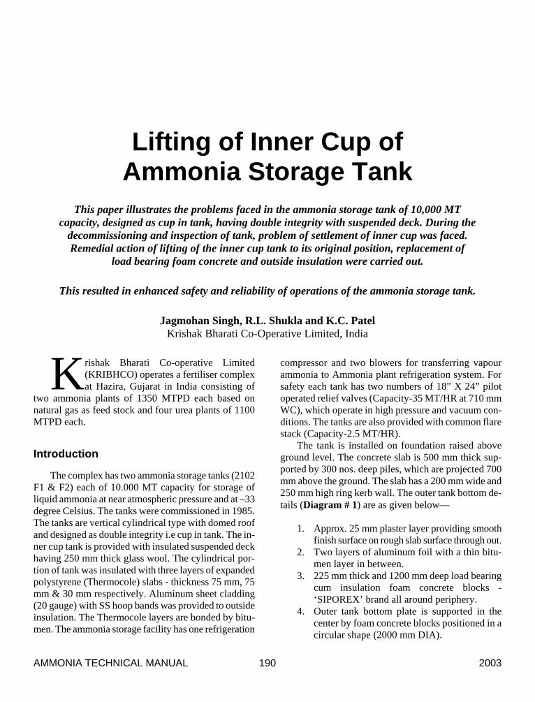
lifting of inner cup of ammonia storage tank
TRANSCRIPT
AMMONIA TECHNICAL MANUAL 2003 190
Lifting of Inner Cup of Ammonia Storage Tank
This paper illustrates the problems faced in the ammonia storage tank of 10,000 MT capacity, designed as cup in tank, having double integrity with suspended deck. During the
decommissioning and inspection of tank, problem of settlement of inner cup was faced. Remedial action of lifting of the inner cup tank to its original position, replacement of
load bearing foam concrete and outside insulation were carried out.
This resulted in enhanced safety and reliability of operations of the ammonia storage tank.
Jagmohan Singh, R.L. Shukla and K.C. Patel Krishak Bharati Co-Operative Limited, India
rishak Bharati Co-operative Limited (KRIBHCO) operates a fertiliser complex at Hazira, Gujarat in India consisting of
two ammonia plants of 1350 MTPD each based on natural gas as feed stock and four urea plants of 1100 MTPD each.
Introduction
The complex has two ammonia storage tanks (2102 F1 & F2) each of 10.000 MT capacity for storage of liquid ammonia at near atmospheric pressure and at –33 degree Celsius. The tanks were commissioned in 1985. The tanks are vertical cylindrical type with domed roof and designed as double integrity i.e cup in tank. The in-ner cup tank is provided with insulated suspended deck having 250 mm thick glass wool. The cylindrical por-tion of tank was insulated with three layers of expanded polystyrene (Thermocole) slabs - thickness 75 mm, 75 mm & 30 mm respectively. Aluminum sheet cladding (20 gauge) with SS hoop bands was provided to outside insulation. The Thermocole layers are bonded by bitu-men. The ammonia storage facility has one refrigeration
compressor and two blowers for transferring vapour ammonia to Ammonia plant refrigeration system. For safety each tank has two numbers of 18” X 24” pilot operated relief valves (Capacity-35 MT/HR at 710 mm WC), which operate in high pressure and vacuum con-ditions. The tanks are also provided with common flare stack (Capacity-2.5 MT/HR).
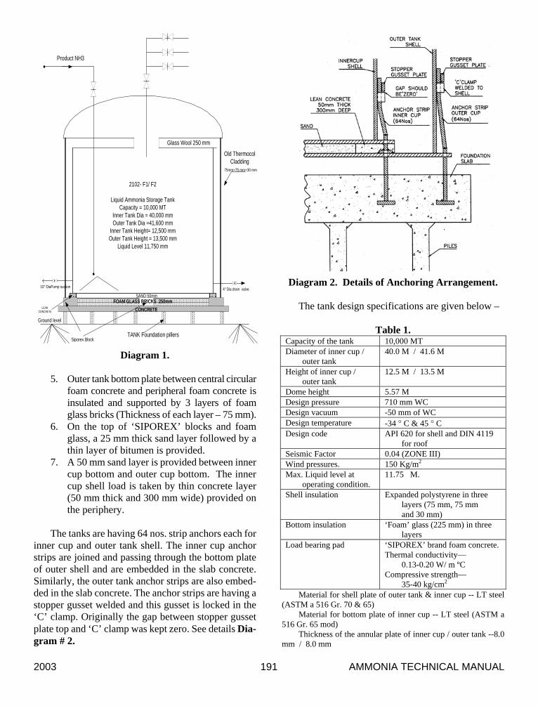
The tank is installed on foundation raised above ground level. The concrete slab is 500 mm thick sup-ported by 300 nos. deep piles, which are projected 700 mm above the ground. The slab has a 200 mm wide and 250 mm high ring kerb wall. The outer tank bottom de-tails (Diagram # 1) are as given below—
1. Approx. 25 mm plaster layer providing smooth
finish surface on rough slab surface through out. 2. Two layers of aluminum foil with a thin bitu-
men layer in between. 3. 225 mm thick and 1200 mm deep load bearing
cum insulation foam concrete blocks - ‘SIPOREX’ brand all around periphery.
4. Outer tank bottom plate is supported in the center by foam concrete blocks positioned in a circular shape (2000 mm DIA).
K
2003 AMMONIA TECHNICAL MANUAL 191
CONCRETE
SAND 50mm
TANK Foundation pillers
2102- F1/ F2
Liquid Ammonia Storage TankCapacity = 10,000 MT
Inner Tank Dia = 40,000 mmOuter Tank Dia =41,600 mm
Inner Tank Height= 12,500 mmOuter Tank Height = 13,500 mm
Liquid Level 11,750 mm
Old ThermocolCladding
75mm+75 mm+30 mm
Product NH3
Ground level
4" Dia drain valve10" DiaPump suction
Glass Wool 250 mm
Siporex Block
FOAM GLASS BRICKS 250mmLEAN
CONCRETE
Diagram 1. 5. Outer tank bottom plate between central circular
foam concrete and peripheral foam concrete is insulated and supported by 3 layers of foam glass bricks (Thickness of each layer – 75 mm).
6. On the top of ‘SIPOREX’ blocks and foam glass, a 25 mm thick sand layer followed by a thin layer of bitumen is provided.
7. A 50 mm sand layer is provided between inner cup bottom and outer cup bottom. The inner cup shell load is taken by thin concrete layer (50 mm thick and 300 mm wide) provided on the periphery.
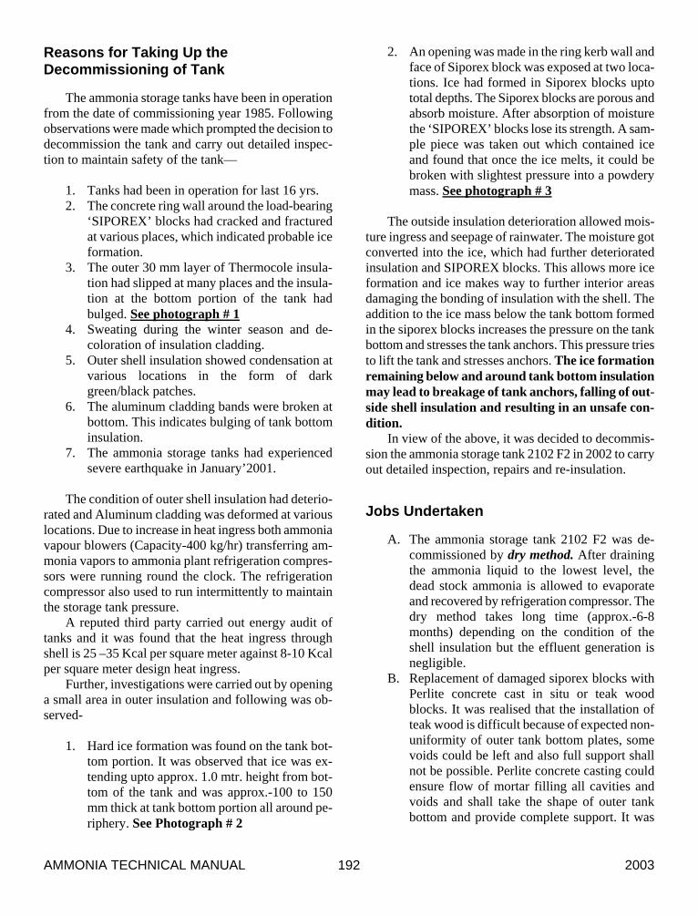
The tanks are having 64 nos. strip anchors each for
inner cup and outer tank shell. The inner cup anchor strips are joined and passing through the bottom plate of outer shell and are embedded in the slab concrete. Similarly, the outer tank anchor strips are also embed-ded in the slab concrete. The anchor strips are having a stopper gusset welded and this gusset is locked in the ‘C’ clamp. Originally the gap between stopper gusset plate top and ‘C’ clamp was kept zero. See details Dia-gram # 2.
Diagram 2. Details of Anchoring Arrangement.
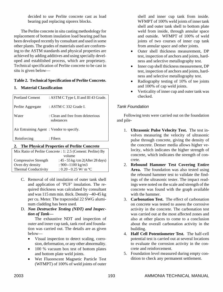
The tank design specifications are given below –
Table 1. Capacity of the tank 10,000 MT Diameter of inner cup /
outer tank 40.0 M / 41.6 M
Height of inner cup / outer tank
12.5 M / 13.5 M
Dome height 5.57 M Design pressure 710 mm WC Design vacuum -50 mm of WC Design temperature -34 ° C & 45 ° C Design code API 620 for shell and DIN 4119
for roof Seismic Factor 0.04 (ZONE III) Wind pressures. 150 Kg/m2 Max. Liquid level at
operating condition. 11.75 M.
Shell insulation Expanded polystyrene in three layers (75 mm, 75 mm and 30 mm)
Bottom insulation ‘Foam’ glass (225 mm) in three layers
Load bearing pad ‘SIPOREX’ brand foam concrete. Thermal conductivity—
0.13-0.20 W/ m ºC Compressive strength—
35-40 kg/cm2 Material for shell plate of outer tank & inner cup -- LT steel
(ASTM a 516 Gr. 70 & 65) Material for bottom plate of inner cup -- LT steel (ASTM a
516 Gr. 65 mod) Thickness of the annular plate of inner cup / outer tank --8.0
mm / 8.0 mm
AMMONIA TECHNICAL MANUAL 2003 192
Reasons for Taking Up the Decommissioning of Tank
The ammonia storage tanks have been in operation from the date of commissioning year 1985. Following observations were made which prompted the decision to decommission the tank and carry out detailed inspec-tion to maintain safety of the tank—
1. Tanks had been in operation for last 16 yrs. 2. The concrete ring wall around the load-bearing
‘SIPOREX’ blocks had cracked and fractured at various places, which indicated probable ice formation.
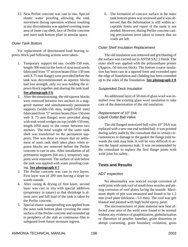
3. The outer 30 mm layer of Thermocole insula-tion had slipped at many places and the insula-tion at the bottom portion of the tank had bulged. See photograph # 1
4. Sweating during the winter season and de-coloration of insulation cladding.
5. Outer shell insulation showed condensation at various locations in the form of dark green/black patches.
6. The aluminum cladding bands were broken at bottom. This indicates bulging of tank bottom insulation.
7. The ammonia storage tanks had experienced severe earthquake in January’2001.
The condition of outer shell insulation had deterio-
rated and Aluminum cladding was deformed at various locations. Due to increase in heat ingress both ammonia vapour blowers (Capacity-400 kg/hr) transferring am-monia vapors to ammonia plant refrigeration compres-sors were running round the clock. The refrigeration compressor also used to run intermittently to maintain the storage tank pressure.
A reputed third party carried out energy audit of tanks and it was found that the heat ingress through shell is 25 –35 Kcal per square meter against 8-10 Kcal per square meter design heat ingress.
Further, investigations were carried out by opening a small area in outer insulation and following was ob-served-
1. Hard ice formation was found on the tank bot-
tom portion. It was observed that ice was ex-tending upto approx. 1.0 mtr. height from bot-tom of the tank and was approx.-100 to 150 mm thick at tank bottom portion all around pe-riphery. See Photograph # 2
2. An opening was made in the ring kerb wall and face of Siporex block was exposed at two loca-tions. Ice had formed in Siporex blocks upto total depths. The Siporex blocks are porous and absorb moisture. After absorption of moisture the ‘SIPOREX’ blocks lose its strength. A sam-ple piece was taken out which contained ice and found that once the ice melts, it could be broken with slightest pressure into a powdery mass. See photograph # 3
The outside insulation deterioration allowed mois-
ture ingress and seepage of rainwater. The moisture got converted into the ice, which had further deteriorated insulation and SIPOREX blocks. This allows more ice formation and ice makes way to further interior areas damaging the bonding of insulation with the shell. The addition to the ice mass below the tank bottom formed in the siporex blocks increases the pressure on the tank bottom and stresses the tank anchors. This pressure tries to lift the tank and stresses anchors. The ice formation remaining below and around tank bottom insulation may lead to breakage of tank anchors, falling of out-side shell insulation and resulting in an unsafe con-dition.
In view of the above, it was decided to decommis-sion the ammonia storage tank 2102 F2 in 2002 to carry out detailed inspection, repairs and re-insulation.
Jobs Undertaken
A. The ammonia storage tank 2102 F2 was de-commissioned by dry method. After draining the ammonia liquid to the lowest level, the dead stock ammonia is allowed to evaporate and recovered by refrigeration compressor. The dry method takes long time (approx.-6-8 months) depending on the condition of the shell insulation but the effluent generation is negligible.
B. Replacement of damaged siporex blocks with Perlite concrete cast in situ or teak wood blocks. It was realised that the installation of teak wood is difficult because of expected non-uniformity of outer tank bottom plates, some voids could be left and also full support shall not be possible. Perlite concrete casting could ensure flow of mortar filling all cavities and voids and shall take the shape of outer tank bottom and provide complete support. It was
2003 AMMONIA TECHNICAL MANUAL 193
decided to use Perlite concrete cast as load bearing pad replacing siporex blocks.
The Perlite concrete in situ casting methodology for
replacement of bottom insulation load bearing pad has been developed recently by consultant and used in some other plants. The grades of materials used are conform-ing to the ASTM standards and physical properties are achieved by adding additives and using specially devel-oped and established process, which are proprietary. Technical specification of Perlite concrete to be cast in situ is given below—
Table 2. Technical Specification of Perlite Concrete.
1. Material Classification
Portland Cement : ASTM C Type I, II and III 43 Grade.
Perlite Aggregate : ASTM C 332 Grade I.
Water : Clean and free from deleterious substances
Air Entraining Agent : Vendor to specify.
Reinforcing : Fibers
2. The Physical Properties of Perlite Concrete Mix Ratio of Perlite Concrete : 1: 2.5 (Cement: Perlite) By volume
Compressive Strength : 45 - 55 kg /cm 2(After 28 days) Oven dry density : 900--1100 kg/m3 Thermal Conductivity : 0.20 - 0.25 W/ m ºC
C. Removal of old insulation of outer tank shell
and application of ‘PUF’ insulation. The re-quired thickness was calculated by consultant and was 115 mm min. thick. Density –40-45 kg per cu. Meter. The trapezoidal 22 SWG alumi-num cladding has been used.
D. Non Destructive Testing (NDT) and Inspec-tion of Tank—
The exhaustive NDT and inspection of outer and inner cup tank, tank roof and founda-tion was carried out. The details are as given below— • Visual inspection to detect scaling, corro-
sion, deformation, or any other abnormality. • 100 % vacuum box test of bottom plates
and bottom plate weld joints. • Wet Fluorescent Magnetic Particle Test
(WFMPT) of 100% of weld joints of outer
shell and inner cup tank from inside. WFMPT of 100% weld joints of inner tank shell and outer tank shell to bottom plate weld from inside, through annular space and outside. WFMPT of 100% of weld joints of two courses of inner cup tank from annular space and other joints.
• Outer shell thickness measurement, DP test, inspection of anchors and joints, hard-ness and selective metallography test.
• Inner cup shell thickness measurement, DP test, inspection of anchors and joints, hard-ness and selective metallography test.
• Radiography testing of 10% of tee joints and 100% of cap weld joints.
• Verticality of inner cup and outer tank was checked.
Tank Foundation
Following tests were carried out on the foundation and pile-
1. Ultrasonic Pulse Velocity Test. The test in-
volves measuring the velocity of ultrasonic pulse through concrete, giving the density of the concrete. Denser media allows higher ve-locity, which indicates the higher strength of concrete, which indicates the strength of con-crete.
2. Rebound Hammer Test Covering Entire Area. The foundation was also tested using the rebound hammer test to validate the find-ings of the ultrasonic tester. The impact read-ings were noted on the scale and strength of the concrete was found with the graph available with the hammer.
3. Carbonation Test. The effect of carbonation on concrete was tested to assess the corrosive activity in the concrete. The carbonation test was carried out at the most affected zones and also at other places to come to a conclusion about the overall carbonation activity in the building.
4. Half Cell Potentiometer Test. The half-cell potential test is carried out at several locations to evaluate the corrosion activity in the con-crete and reinforcement.
5. Foundation level measured during empty con-dition to check any permanent settlement.
AMMONIA TECHNICAL MANUAL 2003 194
Hydro-Pneumatic Test
Hydro-Pneumatic Test was carried out to ensure the soundness of outer tank shell.
E. Welding of 100 mm wide SS 304 (2.0 mm
thick) strip on the outer periphery of roof to safeguard the new insulation from being dam-aged by the birds like Parrots for nesting, which later results in water seepage in the insulation.
Problem of Settlement of Inner Cup and Effect of Ice
After entry inside the inner cup, a slope around the periphery in the bottom plate near the shell was ob-served. It indicated settlement of the inner cup. For con-firmation, the bitumen seal provided over lean concrete in the annular space for preventing any ammonia liquor from seeping into the sand layer at the bottom of the in-ner cup was removed and retaining ring was cut. Fol-lowing observations were made—
1. The original 50 mm gap between inner cup
tank bottom and outer tank bottom had reduced and was found to be in the range of. 6.0 mm to 36 mm.
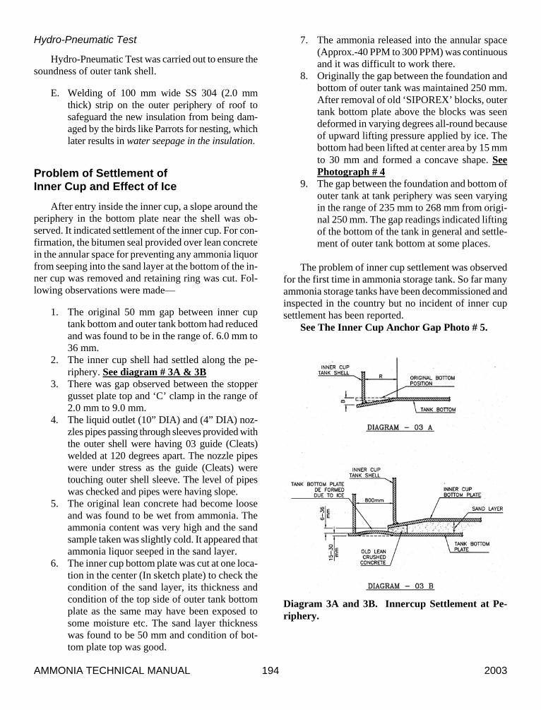
2. The inner cup shell had settled along the pe-riphery. See diagram # 3A & 3B
3. There was gap observed between the stopper gusset plate top and ‘C’ clamp in the range of 2.0 mm to 9.0 mm.
4. The liquid outlet (10” DIA) and (4” DIA) noz-zles pipes passing through sleeves provided with the outer shell were having 03 guide (Cleats) welded at 120 degrees apart. The nozzle pipes were under stress as the guide (Cleats) were touching outer shell sleeve. The level of pipes was checked and pipes were having slope.
5. The original lean concrete had become loose and was found to be wet from ammonia. The ammonia content was very high and the sand sample taken was slightly cold. It appeared that ammonia liquor seeped in the sand layer.
6. The inner cup bottom plate was cut at one loca-tion in the center (In sketch plate) to check the condition of the sand layer, its thickness and condition of the top side of outer tank bottom plate as the same may have been exposed to some moisture etc. The sand layer thickness was found to be 50 mm and condition of bot-tom plate top was good.
7. The ammonia released into the annular space (Approx.-40 PPM to 300 PPM) was continuous and it was difficult to work there.
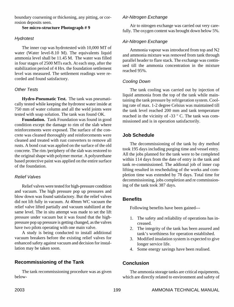
8. Originally the gap between the foundation and bottom of outer tank was maintained 250 mm. After removal of old ‘SIPOREX’ blocks, outer tank bottom plate above the blocks was seen deformed in varying degrees all-round because of upward lifting pressure applied by ice. The bottom had been lifted at center area by 15 mm to 30 mm and formed a concave shape. See Photograph # 4
9. The gap between the foundation and bottom of outer tank at tank periphery was seen varying in the range of 235 mm to 268 mm from origi-nal 250 mm. The gap readings indicated lifting of the bottom of the tank in general and settle-ment of outer tank bottom at some places.
The problem of inner cup settlement was observed
for the first time in ammonia storage tank. So far many ammonia storage tanks have been decommissioned and inspected in the country but no incident of inner cup settlement has been reported.
See The Inner Cup Anchor Gap Photo # 5.
Diagram 3A and 3B. Innercup Settlement at Pe-riphery.
2003 AMMONIA TECHNICAL MANUAL 195
Reasons for Settlement of Inner Cup and Ice Formation at Tank Bottom
In other ammonia storage tanks minor cracks only in the lean concrete ring without any settlement of inner cup have been observed and local repair/ replacement had been carried out. The problem was analysed for the effects it may have on future operations and safety of the ammonia storage tank. The settlement of inner cup shell had deformed the cup bottom and it was presumed that stresses had developed. The higher stresses whose accurate assessment is difficult, may lead to failure at particular locations. The actual settlement was com-pared with permissible settlement as per the guidelines given in standard for Tank Inspection, Repair, Alter-nation, And Reconstruction API standard 653-Second edition 1995 Appendix-B Cl. B.2.3.1, B Cl.2.3.2 & B.3.3 and calculated. Values thus achieved were compared with the measurements and inner cup settlement was found to be higher at some locations than the limits. The formula used is given below---
B = 0.37 R
Where:
B = Settlement, Inches R = Radius Width of Settle Area, in feet
For the measurement of actual depth of settlement,
calculated permissible depth of settlement and im-provement in actual depth of settlement after lifting of the inner cup is given in Table 4 with procedure adopted for lifting.
Following are the possible reasons for inner cup settlement problem---
1. The north Gujarat had experienced an earth-
quake of magnitude of 7.6 on Richter scale. The Surat region had experienced the same earthquake of magnitude of 6.0 on Richter scale for approx.-90 seconds. At that time, ammonia storage tank had approx. 3861 MT of liquid ammonia.
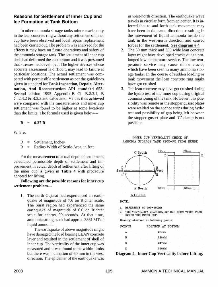
The earthquake of above magnitude might have damaged the load bearing LEAN concrete layer and resulted in the settlement of shell of inner cup. The verticality of the inner cup was measured and it was found to be within limits but there was inclination of 60 mm in the west direction. The epicenter of the earthquake was
in west-north direction. The earthquake wave travels in circular form from epicenter. It is in-ferred that to and forth tank movement may have been in the same direction, resulting in the movement of liquid ammonia inside the tank in the west-north direction and caused forces for the settlement. See diagram # 4
2. The 50 mm thick and 300 wide lean concrete layer might have developed cracks due to pro-longed low temperature service. The low tem-perature service may cause minor cracks, which have been seen in many ammonia stor-age tanks. In the course of sudden loading or tank movement the lean concrete ring might have got crushed.
3. The lean concrete may have got crushed during the hydro test of the inner cup during original commissioning of the tank. However, this pos-sibility was remote as the stopper gusset plates were welded on the anchor strips during hydro test and possibility of gap being left between the stopper gusset plate and ‘C’ clamp is not possible.
Diagram 4. Inner Cup Verticality before Lifting.
AMMONIA TECHNICAL MANUAL 2003 196
4. The tank shell insulation ends at bottom in straight line. The tank foundation has a kerb wall to provide a retaining ring for the insulation at the face of the siporex blocks. An insulation joints at ninety degrees Thermocole insulation was provided as a cover for the filled insulation. However, due to long service and slippage of cladding the insulation joint had been deformed and opened up allowing ingress of the rainwater and atmospheric moisture. The layer of bitumen had cracked at many places because of years of service and moisture reached up to the face of siporex blocks and tank shell. Thereafter, further accumulation of ice had taken place through the damaged insulation slowly resulting in the com-plete ingress of ice in siporex blocks and build up on shell bottom.
5. There is no evidence of the siporex blocks be-ing given any water proof treatment, which would have sealed the cells of foam concrete saving the ‘siporex’ blocks from losing their strength and exerting lifting pressure of the tank bottom because of moisture ingress.
Why to Lift the Inner Cup Tank
The problem was studied and it was realised that if not attended to following complications may be faced—
1. Failure of bottom weld joint between inner cup
shell and bottom annular plates because of high stresses induced by deformation near inner cup shell.
2. Failure of outlet nozzle pipe (10” DIA & 4” DIA), which were under stress and had a slope resulting in unsafe condition. The weight of in-ner cup shell was being partially transferred to the nozzle pipes, which were found resting on outer tank shell.
3. Metal to metal contact between bottom plates of outer tank and inner cup. This may have resulted in notch formation and possibility of failure of outer tank bottom plate may have increased.
4. If left unchecked the verticality of inner cup may have been affected adversely with the fur-ther settlement and may have exceeded the permissible limit of 5.0 mm per meter of height as per code API 620. This shall have resulted in unequal loads on the inner cup anchors and increased possibility of failure of inner cup an-chors in future.
Remedial Measures
Lifting of Inner Cup
After review it was decided to lift and level the in-ner cup to the fullest extent possible to reduce the stresses developed in the shell and nozzle pipes and re-move the gap between the stopper gusset plate and ‘c’ clamp. The gap at the stopper plate should be zero as during any movement forces the tank anchors should hold the tank and not allow lifting upwards.
Following lifting procedure and works were exe-cuted—
Lifting Procedure for Inner Cup
The inner cup lifting procedure is given below— 1. The verticality of the Inner Tank at 16 loca-
tions equally distributed was checked and re-corded.
2. All the anchors were serial numbered. 3. The gap between Outer Tank bottom and Inner
Tank bottom every 500mm from the anchor strip was checked and recorded.
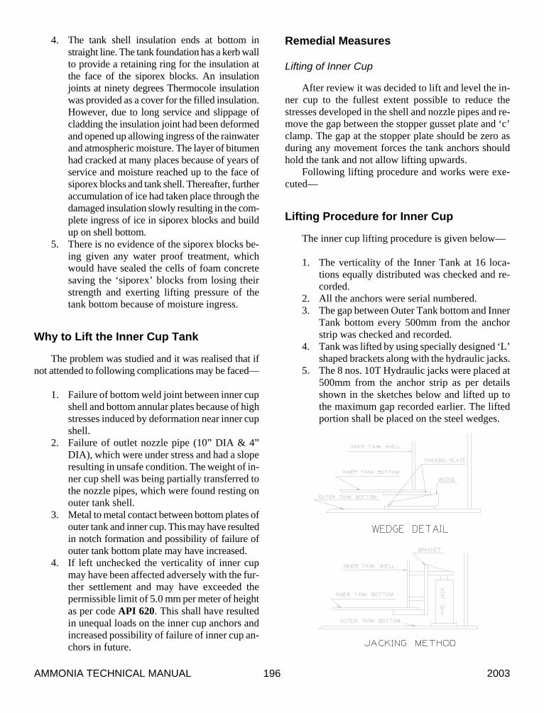
4. Tank was lifted by using specially designed ‘L’ shaped brackets along with the hydraulic jacks.
5. The 8 nos. 10T Hydraulic jacks were placed at 500mm from the anchor strip as per details shown in the sketches below and lifted up to the maximum gap recorded earlier. The lifted portion shall be placed on the steel wedges.
2003 AMMONIA TECHNICAL MANUAL 197
6. It was imperative that during tank lifting by hydraulic jacks, the stresses induced should not cross the elastic range of the metal, thereby preventing any deformation/ damage to the in-ner cup shell. Before lifting was started foil type strain gauges were fixed at the predefined locations on the shell, bottom plate and nozzle pipes in two directions longitudinal and trans-verse with a dummy gauge. At total 45 loca-tions active 90 nos. strain gauges were fixed to monitor the stress level during lifting of inner cup. The maximum strain allowed during lift-ing was 1000-micro strain. Consultant gave the value of allowable strain of 1000-micron strain. Lifting was to be stopped at the location once the strain values were observed in the excess of the value of 1000 micro.
7. The lifting was commenced from the location where maximum gap was available. Subse-quently, the tank was lifted gradually in the span of 5mm per lift.
8. The inner cup was lifted till the gap between the stopper gusset and ‘c’ clamp becomes zero and the strain values do not cross 1000 micro. In this condition whatever, the gap was measured be-tween the inner cup bottom and top of the outer tank bottom plate and teak wood wedges (Hav-ing minimum compressive strength perpendicu-lar to the grain-60 KG/CM2) were installed at both the ends of the each anchors (64 nos.)
The inner cup could be lifted in a range of 5 mm to 19 mm, when the gap between stopper
gusset and ‘C’ clamp became zero. After lifting of the inner cup the settlement readings were taken and improvements were seen. The com-parison table is given in Table-4.
9. Accordingly, the rest of the tank portion was lifted and placed on steel wedges and steel plates.
10. Once the required gap was achieved then the steel wedges were further inserted inside to create additional approx. 1mm gap to facilitate the placement of teak wooden flats.
11. The measured strain data clearly shows the re-duction in strain in 10” NB and 4” NB nozzle pipes 131 and 150 micro strain respectively af-ter lifting of the inner cup. Strain values re-corded during lifting are much below the calcu-lated value of 1000 micron strain.
During lifting no portion of the inner cup anchor strip etc. got over-stressed and there-fore lifting operation has been quite safe and successful.
12. 128 nos. teak wooden flat of 300mm long and 100mm wide of the required thickness were in-stalled on both side of the anchor strips and the steel wedges were removed.
13. After the placement of teak wood flats, final verticality of the Inner Tank was checked and recorded, the same was within limits.
14. On completion of above-mentioned activities, the bottom was released for Perlite concreting.
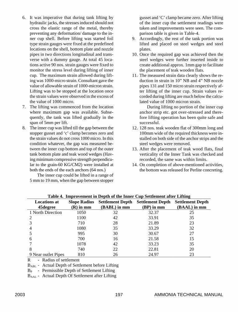
Table 4. Improvement in Depth of the Inner Cup Settlement after Lifting Locations at
45degree Slope Radius
(R) in mm Settlement Depth
(BABL) in mm Settlement Depth
(BP) in mm Settlement Depth (BAAL) in mm
1 North Direction 1050 32 32.37 25 2 1100 42 33.91 35 3 710 28 21.89 23 4 1080 35 33.29 32 5 995 30 30.67 27 6 700 16 21.58 15 7 1078 42 33.23 35 8 740 22 22.81 20 9 Near outlet Pipes 810 26 24.97 23
R - Radius of settlement BABL - Actual Depth of Settlement before Lifting BP - Permissible Depth of Settlement Lifting BAAL - Actual Depth Of Settlement after Lifting
AMMONIA TECHNICAL MANUAL 2003 198
15. New Perlite concrete was cast in situ. Special elastic water proofing allowing the tank movement during operation without resulting in any discontinuity was applied covering some area of inner cup shell, face of Perlite concrete and outer tank bottom plate in annular space.
Outer Tank Bottom
For replacement of deteriorated load bearing si-porex block pad following actions were taken-
1. Temporary support 64 nos. (width-150 mm,
length-300 mm) in the form of structural stools fabricated from “I” section beam (Size-150 mm web X 75 mm flange) were provided before the tank was decommissioned as siporex blocks had lost strength, only ice was holding the si-porex block together and sharing the tank load. See photograph # 6
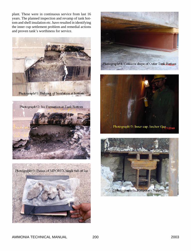
2. After decommissioning, the old siporex blocks were removed between two anchors in a stag-gered manner and simultaneously permanent supports (width-150 mm, length-1050 mm) fabricated from “I” section beam (Size-150 mm web X 75 mm flange) were provided along with teak wood wedges on top (width-150 mm, length-1050 mm) in the center between two anchors. The total weight of the outer tank shell was transferred on the permanent sup-ports. This was done to ensure that no settle-ment of outer tank shell takes place when si-porex blocks are removed before the Perlite concrete is cast in situ. After installation of all permanent supports (64 nos.), temporary sup-ports were removed. The surface of slab below the tank was applied with water proofing coat-ing. See photograph # 7
3. The Perlite concrete was cast in two layers. First layer was of 200 mm having a slope to-wards outside.
4. After curing & drying of first layer, second layer was cast in situ with special additives (proprietary in nature) so that shrinkage is al-most zero and full load of the tank is taken by the Perlite concrete.
5. Special elastic waterproofing was applied from the outer tank bottom plate covering the outer surface of the Perlite concrete and extended up to periphery of the slab as continuous film to safeguard from future moisture ingress.
6. The formation of concave surface in the outer tank bottom plates was reviewed and it was ob-served that the deformation is still within ac-ceptable limits and repair of the same is not needed. However, during Perlite concrete cast-ing precautions were taken to ensure that no voids are left.
Outer Shell Insulation Replacement
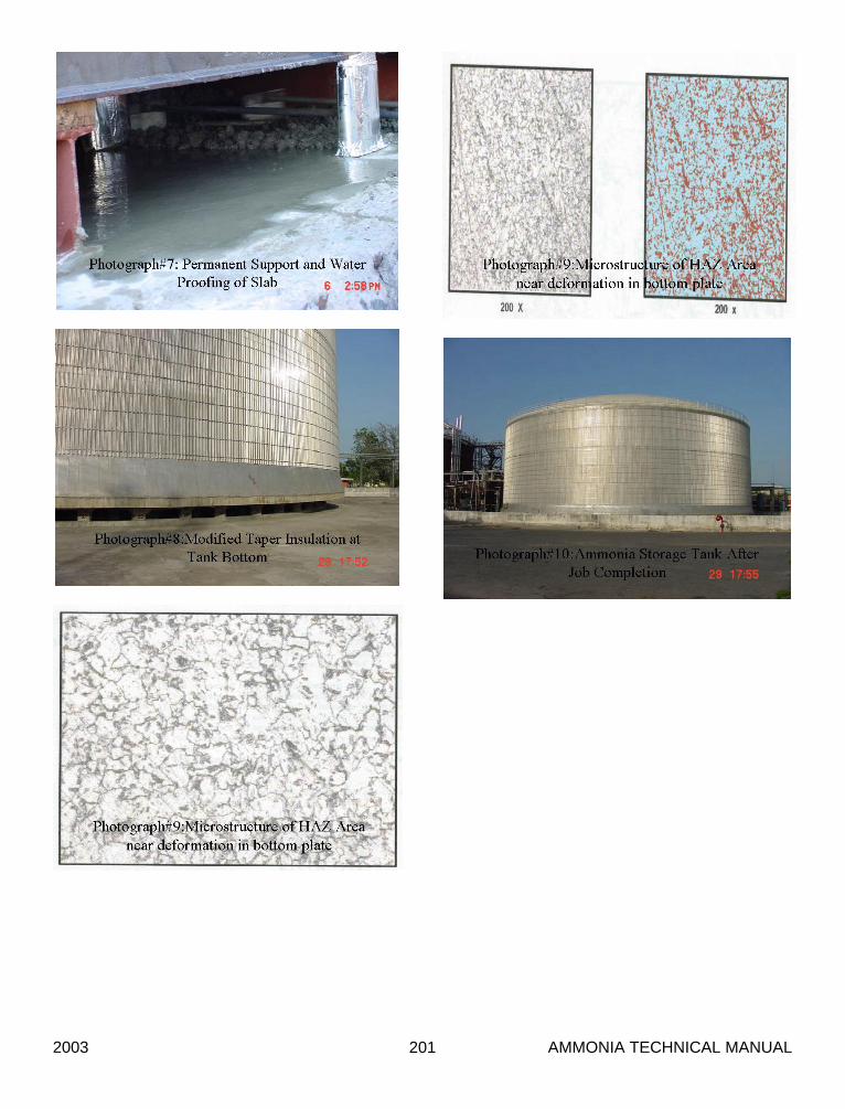
The old insulation was removed and grit blasting of the surface was carried out to ASTM SA2.5 finish. The outer shell was applied with the polyurethane primer (Approx.-50 micron thick). The bottom course insula-tion has been cast in a tapered form and extended upto the edge of foundation and cladding has been extended up to the sides of the foundation. See photograph # 8
Suspended Deck Insulation
An additional layer of 50 mm of glass wool was in-stalled over the existing glass wool insulation to take care of the deterioration of the old insulation.
Replacement of 10” DIA Liquid Outlet Ball Valve
The old flanged motorized ball valve 10” DIA was replaced with a new one end welded ball. it was pointed during safety audit by the consultant that in certain cir-cumstances or damage to the gasket the flange joint to-wards the tank may leak. It will be very difficult to ar-rest the liquid ammonia leak. It was recommended by the consultant to replace the first flange joints with weld joint for safety.
Tests and Results
NDT inspection
No abnormality was noticed except corrosion of weld joint with tank roof of small-bore nozzles and pit-ting corrosion of roof plates facing the seaside. Maxi-mum depth of pits was measured and found to be 1.2 mm (roof plate thickness –5.0 mm). The roof was grit blasted and painted with high build epoxy paint.
The microstructures of plate material near heat af-fected zone area of the weld were found to be normal without any evidence of graphitization, globularisation or distortion of pearlite lamellae, grain distortion or abrupt coarsening, grain boundary oxidation, grain
2003 AMMONIA TECHNICAL MANUAL 199
boundary coarsening or thickening, any pitting, or cor-rosion deposits seen.
See micro-structure Photograph # 9
Hydrotest
The inner cup was hydrotested with 10,000 MT of water (Water level-8.10 M). The equivalents liquid ammonia level shall be 11.45 M. The water was filled in four stages of 2500 MTs each. At each step, after the stabilization period of 4 Hrs. the foundation settlement level was measured. The settlement readings were re-corded and found satisfactory.
Other Tests
Hydro-Pneumatic Test. The tank was pneumati-cally tested while keeping the hydrotest water inside at 750 mm of water column and all the weld joints were tested with soap solution. The tank was found OK.
Foundation. Tank Foundation was found in good condition except the damage to rim of the slab where reinforcements were exposed. The surface of the con-crete was cleaned thoroughly and reinforcements were cleaned and treated with rust converters to remove all rusts. A bond coat was applied on the surface of the old concrete. The rim /periphery of the slab was restored to the original shape with polymer mortar. A polyurethane based protective paint was applied on the entire surface of the foundation.
Relief Valves
Relief valves were tested for high-pressure condition and vacuum. The high pressure pop up pressures and blow down was found satisfactory. But the relief valves did not lift fully in vacuum. At 40mm WC vacuum the relief valve lifted partially and vacuum stabilized at the same level. The in situ attempt was made to set the lift pressure under vacuum but it was found that the high-pressure pop up pressure is getting changed, as the valves have two pilots operating with one main valve.
A study is being conducted to install additional vacuum breakers before the existing relief valves for enhanced safety against vacuum and decision for instal-lation may be taken soon.
Recommissioning of the Tank
The tank recommissioning procedure was as given below-
Air-Nitrogen Exchange
Air to nitrogen exchange was carried out very care-fully. The oxygen content was brought down below 5%.
Air-Nitrogen Exchange
Ammonia vapour was introduced from top and N2 and ammonia mixture was removed from tank through parallel header to flare stack. The exchange was contin-ued till the ammonia concentration in the mixture reached 95%.
Cooling Down
The tank cooling was carried out by injection of liquid ammonia from the top of the tank while main-taining the tank pressure by refrigeration system. Cool-ing rate of max. 1-2 degree Celsius was maintained till the tank level reached 200 mm and tank temperature reached in the vicinity of -33 ° C. The tank was com-missioned and is in operation satisfactorily.
Job Schedule
The decommissioning of the tank by dry method took 195 days including purging time and vessel entry. All the jobs planned for the tank were to be completed within 114 days from the date of entry in the tank and tank re-commissioned. The addional job of inner cup lifting resulted in rescheduling of the works and com-pletion time was extended by 78 days. Total time for decommissioning, jobs completion and re commission-ing of the tank took 387 days.
Benefits
Following benefits have been gained--- 1. The safety and reliability of operations has in-
creased. 2. The integrity of the tank has been assured and
tank’s worthiness for operation established. 3. Modified insulation system is expected to give
longer service life. 4. Some energy savings have been realised.
Conclusion
The ammonia storage tanks are critical equipments, which are directly related to environment and safety of
AMMONIA TECHNICAL MANUAL 2003 200
plant. These were in continuous service from last 16 years. The planned inspection and revamp of tank bot-tom and shell insulation etc. have resulted in identifying the inner cup settlement problem and remedial actions and proven tank’s worthiness for service.
2003 AMMONIA TECHNICAL MANUAL 201