lift is the force normal to the fluid flow unit #...
TRANSCRIPT

Lift 8.4
Lift is the force normal to the fluid flowUnit # 7

Comparison of Drags on
a well designed Jet plane

Lift Coefficient
• Lift, L is the force normal to the direction of object’s velocity
• Lift coefficient, CL is defined asAU
LCL2
21 ρ
=

Computation of Lift coefficient in the lab• Lift is found by integrating the pressure above
and below the object as is done in the Fluids laboratory

NACA series airfoilNACA 5-Digit Series: 2 3 0 1 2
2 - max camber in % of chord30 – position of max. camber in 2/100 of chord (eg 1/2x30 = 15%) 12 – Max. thickness in % chord (eg. 12%)
These sections were generated from a more or less prescribed pressure distribution and were meant to achieve some laminar flow.
NACA 6-Digit Series: 6 3, 2 - 2 1 26- Six series3 – location of minimum pressure in 1/10 Chord (x/c = .3)2 – one tenth of max2 – ideal CL in one tenth (CL= 0.2)12 – Max thickness in % of chord ( 12%)
After the six-series sections, airfoil design became much more specialized for the particular application.
Design your airfoil visit http://www.desktopaero.com/appliedaero/airfoils1/airfoilgeometry.html
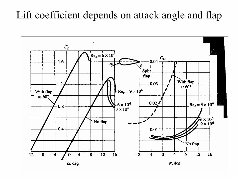
Lift coefficient depends on attack angle and flap

Polar Plot (CL vs CD) for NACA 16

Stall speed
• Lift supports the weight of the aircraft• L = W= Clmax[1/2ρ Vstall
2) (A)• A maximum lift means that there is a
minimum speed, which called stall speed.• It is the speed that determines the landing
speed of an aircraft

Severe separation causes stalling

Lift augmentation devices• Slat
It is placed in front of the airfoil to help increase the momentum of the boundary layer fluid. Thus it delays the separation and enhance the lift
• FlapIt is placed at the rear of the wing it allows higher momentum fluid to replace the weaker fluid in the tail of the wing. Thus it avoid separation. It also increases the drag.

Wing fenceStreamwise vortex is generated to delay separation

Hydrofoil

Airfoil GeometryAirfoil geometry is often characterized by a few parameters such as:
maximum thickness, maximum camber, position of max thickness, position of max camber, and nose radius. One can generate a reasonable airfoil section given these parameters. The NACA 4 digit and 5 digit airfoils were created by superimposing a simple meanline shape with a thickness distribution that was obtained by fitting a couple of popular airfoils of the time: y = ±(t/0.2) * (.2969*x0.5 - .126*x - .3537*x2 + .2843*x3 - .1015*x4)where t is maximum thickness

Solved problem-Walter p440
• A hydrofoil boat (111,767 kg) use hydrofoil section (NACA 16) of average area 16.7 m2. It engine power is 7600 hp. What is the power needed to attain this foil borne speed if maximum lift coefficient for NACA 16 is 0.37
• What is the maximum speed of the boat if the drag then is 97100 N and propulsive efficiency is 38%.

Problem (Munson 9.57)
• If the takeoff speed of a particular airplane is 120 mi/hr at sea level, what will be at Denver (elevation 5000ft) Given air density at 5000 ft is 2.048 unit and that at sea level 2.377 unit.

Drag/Lift Coefficients
• Both lift and drag coefficients depend on angle of attack
• Values are typical for each type of airfoils
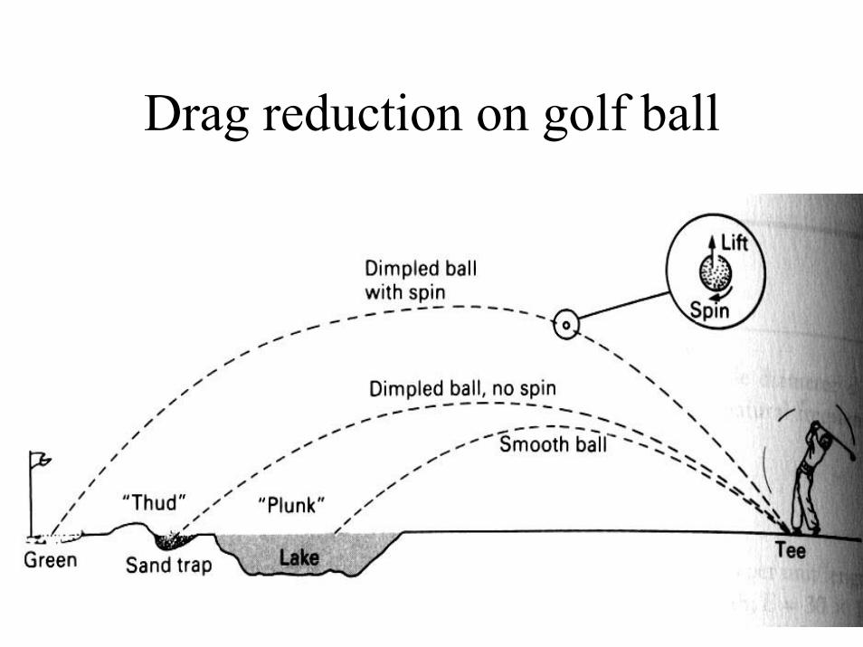
Drag reduction on golf ball

Word problem
• I heard somewhere that a Canadian scientist who wanted to send objects to the space by using powerful projectiles developed a scheme of reducing the drag on the projectile. The device involved some kind of heating of air on the projectile surface. Guess what could be the drag reduction method

Internet Links (cont.)
• 8.4 - Lift and Drag on Airfoils– Airfoil - Startup Problem – Animation:
http://www.cfm.brown.edu/people/beskok/small.mpg– Airfoil Geometry:
http://www.desktopaero.com/appliedaero/airfoils1/airfoilgeometry.html
– FLOW AROUND AN AIRFOIL - Interesting animations showing many different flow characteristics: http://www.idra.unige.it/~irro/profilo_e.html

Internet Links (cont.)
• 8.3.2 - Vortex Shedding– ON-LINE ANIMATIONS:
http://www.city.ac.uk/hydraulics/CFD/animjava.html– Vortex Shedding – Animation:
http://www.engineering.uiowa.edu/~cfd/gallery/images/ani2.mpg– Research of Dr. Kevin D. Jones: Unsteady Aerodynamics - Panel
Methods - An interesting animation of vortex shedding from a flapping wing: http://www.aa.nps.navy.mil/~jones/research/unsteady/panel_methods/anim1/
• 8.3.4 - Cavitation– Cavitation - Some interesting cavitation information:
http://www.rwthaachen.de/iww/English/Forschung/Kavitation/Kavitation.html
– Cavitation & Bubbly Flows - Much cavitation information and references to related publications: http://www1.umn.edu/safl/research/lwr/basic/arndt/