tj12 hydraulic track jack (10 ton) · adding hydraulic fluid a jack that is low on hydraulic fluid...
TRANSCRIPT

USER’S MANUAL SAfEty, OpERAtiON ANd MAiNtENANcE
TJ12HYDRAULIC
TRACK JACK (10 TON)
© 2016 Stanley Black & Decker, Inc.New Britain, CT 06053
U.S.A.72713 9/2016 Ver. 1

2 ► TJ12 User Manual
SERVICING: This manual contains safety, and operation instructions. Stanley Hydraulic Tools recommends that servicing of hydraulic tools, other than routine maintenance, must be per-formed by an authorized and certified dealer. Please read the following warning.
SERIOUS INJURY OR DEATH COULD RESULT FROM THE IMPROPER REPAIR OR SERVICE OF THIS TOOL.
REPAIRS AND / OR SERVICE TO THIS TOOL MUST ONLY BE DONE BY AN AUTHORIZED AND CERTIFIED DEALER.
Repair Kits .............................................................................................. 13
Maintenance & Care ..........................................................................8 - 10 General ................................................................................................ 8 Cleaning .............................................................................................. 8 Hydraulic Fluid ..................................................................................... 8 Replacing Fluid When Necessary .................................................. 8 Annual Hydraulic Fluid Change ...................................................... 8 Purging Air ...................................................................................... 9Inspecting the track jack for damage or leakage. ................................... 10
Operation ........................................................................................... 11-12 Pre-Operation Instructions ................................................................. 11 Raising A Load ................................................................................... 11 Lowering A Load ................................................................................ 11 Horizontal Operation .......................................................................... 11Safety Precautions ..............................................................................5 - 6 Tool Stickers and Tags ......................................................................... 7Specifications ......................................................................................... 13Troubleshooting ...................................................................................... 12Pump Assy Illustration & Parts List .........................................................14Base Illustration & Parts List ...................................................................15Warranty..............................................................See Below
DANGER
TABLE OF CONTENTS
IMPORTANT
To fill out a Product Warranty Validation form, and for information on your warranty, visit Stanleyhydraulics.com and select the Company tab, Warranty.
(NOTE: The warranty Validation record must be submitted to validate the warranty).

TJ12 User Manual ► 3
NOTES
4 ► TJ12 User Manual
SAFETY SYMBOLS
Safety symbols and signal words, as shown below, are used to emphasize all operator, maintenance and repair actions which, if not strictly followed, could result in a life-threatening situation, bodily injury or damage to equip-ment.
This safety alert and signal word indicate an imminently hazardous situa-tion which, if not avoided, will result in death or serious injury.
Always observe safety symbols. They are included for your safety and for the protection of the tool.
LOCAL SAFETY REGULATIONSEnter any local safety regulations here. Keep these instructions in an area accessible to the operator and mainte-nance personnel.
This is the safety alert symbol. It is used to alert you to potential personal injury hazards. Obey all safety messages that follow this symbol to avoid possible injury or death.
This safety alert and signal word indicate a potentially hazardous situation which, if not avoided, could result in death or serious injury.
This safety alert and signal word indicate a potentially hazardous situation which, if not avoided, may result in minor or moderate injury.
This signal word indicates a potentially hazardous situation which, if not avoided, may result in property damage or damage to the equipment.
This signal word indicates a situation which, if not avoided, may result in damage to the equipment.

TJ12 User Manual ► 5
SAFETY PRECAUTIONSTool operators and maintenance personnel must always comply with and work in accordance with the safety precautions and instructions given in this manual and on the stickers and tags attached to the tool and hose.
These safety precautions are given for your safety. Review them carefully before operating the tool and before performing general maintenance or repairs.
Supervising personnel should develop additional precautions relating to the specific work area and local
safety regulations. If so, place the added precautions in the space provided.
GENERAL SAFETY PRECAUTIONS
• The user must be familiar with correct operation, maintenance, and use of the jack. Lack of knowledge can lead to personal injury.
• Operator must start in a work area without bystanders. The operator must be familiar with all prohibited work areas such as excessive slopes, dangerous terrain conditions and extreme climates.
• Always wear safety equipment such as goggles, gloves, head, and safety shoes at all times when operating the tool.
• Warning: Hydraulic fluid under pressure could cause skin injection injury. If you are injured by hydraulic fluid, get medical attention immediately.
• The total load lifted or supported by the jack must never exceed the rated capacity. Excess pressure can result in personal injury. Use a jack with sufficient capacity to lift a load. Keep clear of lifted loads.
• Before each use visually inspect the jack to prevent unsafe conditions from developing. Do not use jacks that are damaged, leaking, altered or in poor condition. See “INSPECTING THE TRACK JACK FOR DAMAGE OR LEAKAGE” on page # 10 for additional information.
• Properly support the jack.
• Do not put poorly balanced or off-center loads on the jack pad or jack. The load can tip and cause personal injury. Do not use in unstable or hazardous positions.
• The jack must be used on flat surfaces to be able to carry the load correctly. The base must be com-pletely supported. Do not push or lift on the ends of the base.
• Do not lift people, or loads with people on them.
• As the load is lifted, use blocks or cribs to guard against a falling load.
• To prevent personal injury, do not allow personnel to go under, or work under or on a load before it is properly secured by suitable means. All personnel must be clear of a load before lowering or lifting.
• Lift only dead weight loads. Do not add additional weight to a lifted load.
• Do not use jacks that are damaged, altered or in poor condition. Do not modify the jack in any way that would affect the compliance of the jack with standard BS EN 1494:2000+A1:2008.
• The reservoir must have sufficient hydraulic fluid to fully stroke the jack. Use only approved hydraulic fluids.

6 ► TJ12 User Manual
GENERAL SAFETY PRECAUTIONS CONTINUED: • Read and understand the operating instructions in this manual, and the ASME B30.1 and EN 1494
safety code for jacks.
• Users must ensure that all safety related decals and stickers are whole and readable. Replace those which become unreadable.
• Never use extreme heat to disassemble a hydraulic ram or cylinder. Metal fatigue can lead to unsafe conditions.
• Be aware of possible "pinch points" of the jack, and stay clear to avoid personal injury.
• When lifting with the edge of the lifting toe, place a wedge between the load and the top of the lifting toe to avoid bending the cylinder column.
• Carry the jack only by the carrying handle. Make sure the jack is in the fully lowered position.
• End users must be trained in the proper use of the jack..
• Remove operating levers when not in use to avoid accidental dislocation of the jack, and reduce the tripping hazard.
• Make sure all personnel are clear of the load before lifting or lowering.
• DO NOT use extenders or accessories unless they are rated for the load, injury or death could result.
• Never use this tool when working around electrified rail unless it is de-energized or you have been properly trained to work on electrified rail. If you are not sure the rail is live or not, you must treat it as being live and dangerous to life.
• The operator should always have the lifting device and load in view during movement.
• To avoid personal injury or equipment damage, all tool repair, maintenance and service must only be performed by authorized and properly trained personnel.
• Never use the tool in an explosive atmosphere, sparks could ignite explosive gas.
SAFETY PRECAUTIONS

TJ12 User Manual ► 7
TOOL STICKERS AND TAGS
RAILROAD HELP DESK STICKER P/N-73680
MANUAL STICKER P/N-28788
CRUSHING HAZARD P/N-31064
STANLEY STICKERP/N-73679
Model Number, Serial Number, 7250 PSI/500 Bar and year of manufacture are
stamped in this location on each jack.

8 ► TJ12 User Manual
MAINTENANCE & CAREGENERAL PROTECTION
Store the Track Jack in an upright position, in a place where it is protected from the elements, abrasive dust, and damage.
Use only recommended repair and replacement parts and materials specified in the Parts List section of this manual.
Do not use the jack for applications it was not designed for.
Use the carrying handle to transport the Track Jack from location to location. Do not carry the Track Jack by inserting the jack handle in the socket.
CLEANING
Establish a routine to keep the jack as free from dirt as possible – daily, or at each shift change, for example.
Jacks exposed to rain, sand, or grit-laden air should be cleaned prior to each use.
Exposed screw threads should be cleaned and re-lubri-cated as necessary.
Keep the cylinder clean at all times. Keep the piston retracted when not in use.
Operating lever and load-bearing surfaces should be free of slippery material or fluids.
Keep tool labels and stickers legible.
HYDRAULIC FLUID
The Track Jack holds approximately 28 ounces/820 cc cubic inches of hydraulic fluid (ISO#15) in its reservoir.
ADDING HYDRAULIC FLUID
A jack that is low on hydraulic fluid will still be able to lift a full load, but not to the full lift height. As the res-ervoir begins to run dry, the handle lever becomes very easy to pump, and the jack stops lifting, this is a sign the jack is low on fluid.
To add oil:1. Fully retract the plunger.2. Make sure relief valve is closed.3. Remove the fill plug (item # 3 on the Pump Assy
Illustration).4. Fill the reservoir with new, clean fluid (use ISO#15
Hydraulic Fluid) to a level 1/8 inch below the bot-tom of the fill plug hole.
ANNUAL FLUID CHANGE
Regardless of usage, the Track Jack hydraulic fluid should be changed annually to ensure proper operation of the jack. To drain the fluid:
1. Thoroughly clean the area around the fill plug.
2. Remove the fill plug and lay the Track Jack on its back to allow the fluid to drain from the fill hole into an appropriate receptacle.
3. Dispose of the used hydraulic fluid in accordance with Environmental Protection Agency regulations.
4. Make sure dirt or other contaminants do not enter the reservoir while the fill plug is removed. When drained, check the fluid for contaminants. If the fluid appears gritty or dirty, flush the reservoir with clean hydraulic fluid before refilling.
5. Refill the reservoir with the recommended hydraulic fluid. Stand the jack upright, and with the piston fully retracted, fill the reservoir until the fluid level is 1/8 inch below the bottom of the fill plug.
6. Before returning the jack to service, fully extend the piston without a load by pumping the pump handle without the long extension handle. If the fluid level is correct, the pump handle will become almost im-possible to pump by hand as the piston reaches full extension. Replace the plug.
Do not overfill or underfill the reser-voir as this may damage the jack.
DO NOT USE BRAKE FLUID OR OTHER NON-APPROVED
SUBSTITUTE FLUIDS. LIGHTER WEIGHT FLUIDS MAY CAUSE THE
JACK TO FAIL UNDER LOAD.
DANGER
WARNING
TJ12 User Manual ► 9
MAINTENANCE & CARE
7. It may be necessary to bleed air out of the cylinder. See instructions below for purging air.
8. Inspect the jack for leaks, cracks, or other damage.
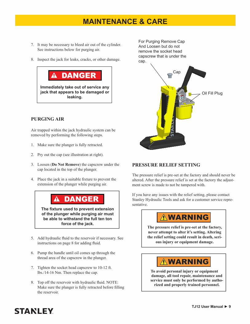
PURGING AIR
Air trapped within the jack hydraulic system can be removed by performing the following steps.
1. Make sure the plunger is fully retracted.
2. Pry out the cap (see illustration at right).
3. Loosen (Do Not Remove) the capscrew under the cap located in the top of the plunger.
4. Place the jack in a suitable fixture to prevent the extension of the plunger while purging air.
5. Add hydraulic fluid to the reservoir if necessary. See instructions on page 8 for adding fluid.
6. Pump the handle until oil comes up through the thread area of the capscrew in the plunger.
7. Tighten the socket head capscrew to 10-12 ft. lbs./14-16 Nm. Then replace the cap.
8. Top off the reservoir with hydraulic fluid. NOTE: Make sure the plunger is fully retracted before filling the reservoir.
The fixture used to prevent extension of the plunger while purging air must be able to withstand the full ten ton
force of the jack.
DANGER
Immediately take out of service any jack that appears to be damaged or
leaking.
DANGER
Oil Fill Plug
For Purging Remove Cap And Loosen but do not remove the socket head capscrew that is under the cap.
Cap
PRESSURE RELIEF SETTING
The pressure relief is pre-set at the factory and should never be altered. After the pressure relief is set at the factory the adjust-ment screw is made to not be tampered with.
If you have any issues with the relief setting, please contact Stanley Hydraulic Tools and ask for a customer service repre-sentative.
The pressure relief is pre-set at the factory, never attempt to alter it’s setting. Altering the relief setting could result in death, seri-
ous injury or equipment damage.
To avoid personal injury or equipment damage, all tool repair, maintenance and service must only be performed by autho-
rized and properly trained personnel.

10 ► TJ12 User Manual
MAINTENANCE & CARE
Never use a damaged track jack, Immediately take out of service any jack that appears to be damaged or leaking
and replace any damaged parts.
DANGER
2. Once a month it is recommended to remove the “Retaining Ring” and “Lifting Toe”, thoroughly inspect the back as well as the front and sides for damage or cracks. Take special note of the areas indicated above with the black arrows.
Retaining Ring
Cap
Lifting Toe
INSPECTING THE TRACK JACK FOR DAMAGE OR LEAKAGE
1. Before each use visually inspect the jack for leaks, cracks, or other damage.

TJ12 User Manual ► 11
OPERATING INSTRUCTIONS
PREOPERATION PROCEDURES
Before putting a new Track Jack into initial service, or after an extended period of being unused, perform a visual inspec-tion for bent, broken, cracked, missing or worn components. (see “INSPECTING THE TRACK JACK FOR DAMAGE OR LEAKAGE”) on page # 10 for more information.Ensure the hydraulic fluid and lubricant level is correct. Fully extend and retract the jack without a load to ensure that the jack is primed and operating properly.
RAISING A LOAD
1. Before using the Track Jack, make sure that it is set on a firm surface capable of bearing the intended load.
2. Make sure the Spindle (item 41) is closed, by turning it clockwise until it is hand tight.
3. Pump the handle by hand until the Toe Lift or Head Lift plate rises to and engages the load.
4. Insert the jack handle fully into the handle socket and pump until the desired lift has been obtained.
5. Remove the jack handle from the handle socket once the load reaches its desired height.
6. Crib or block the load to prevent accidently drop-ping of the load.
LOWERING A LOAD
1. Make sure all personnel are clear of the load.
2. Remove cribbing or blocking if used.
3. Open the Spindle (item 41) by turning it counter-clockwise (open slowly).
4. When the load reaches the desired level, close the Spindle by turning it clockwise until it is hand tight.
HORIZONTAL OPERATION
The Track Jack can also be used horizontally to separate two items, as long as it is placed with the handle socket facing upwards.
1. Place the Track Jack base against the largest, heavi-est, or otherwise least moveable of the two items.
2. Close the Spindle (item 41) by turning it clockwise until hand tight.
3. Pump the handle socket by hand until the lifting toe or the head of the lifting toe firmly engages the more moveable of the two items.
MAKE SURE THAT ALL PERSONNEL ARE CLEAR OF THE LOAD BEFORE ATTEMPTING TO RAISE
OR LOWER THE JACK. SERIOUS INJURY OR DEATH COULD RESULT FROM THE IMPROPER
USE OF THIS TOOL. Use only the recommended length jack handle. DO NOT use longer handles or
extenders. See Spec’s on page 13.
WARNING
DANGER
Overtightening the spindle (item 41) can damage the valve seat. DO NOT use pliers or
wrenches to tighten.
DANGER
Make certain that the lifting toe is fully engaged on the load, and the entire jack is
stable, before proceeding further.
DANGER
DANGER
Head Lift
Toe Lift
Lowering speed is controlled by opening the Spindle more or less. Open slowly to controll the lowering speed. Caution: Opening the Spindle too much will
cause the load to drop quickly.
12 ► TJ12 User Manual
TROUBLESHOOTING
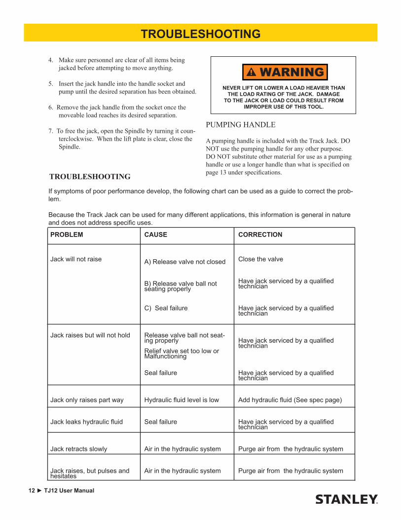
PUMPING HANDLE
A pumping handle is included with the Track Jack. DO NOT use the pumping handle for any other purpose. DO NOT substitute other material for use as a pumping handle or use a longer handle than what is specified on page 13 under specifications.
If symptoms of poor performance develop, the following chart can be used as a guide to correct the prob-lem.
Because the Track Jack can be used for many different applications, this information is general in nature and does not address specific uses.
PROBLEM CAUSE CORRECTION
Jack will not raise A) Release valve not closed Close the valve
B) Release valve ball not seating properly
Have jack serviced by a qualified technician
C) Seal failure Have jack serviced by a qualified technician
Jack raises but will not hold Release valve ball not seat-ing properlyRelief valve set too low or Malfunctioning
Have jack serviced by a qualified technician
Seal failure Have jack serviced by a qualified technician
Jack only raises part way Hydraulic fluid level is low Add hydraulic fluid (See spec page)
Jack leaks hydraulic fluid Seal failure Have jack serviced by a qualified technician
Jack retracts slowly Air in the hydraulic system Purge air from the hydraulic system
Jack raises, but pulses and hesitates
Air in the hydraulic system Purge air from the hydraulic system
4. Make sure personnel are clear of all items being jacked before attempting to move anything.
5. Insert the jack handle into the handle socket and pump until the desired separation has been obtained.
6. Remove the jack handle from the socket once the moveable load reaches its desired separation.
7. To free the jack, open the Spindle by turning it coun-terclockwise. When the lift plate is clear, close the Spindle.
TROUBLESHOOTING
NEVER LIFT OR LOWER A LOAD HEAVIER THAN THE LOAD RATING OF THE JACK. DAMAGE
TO THE JACK OR LOAD COULD RESULT FROM IMPROPER USE OF THIS TOOL.
WARNING

TJ12 User Manual ► 13
SPECIFICATIONS
PerformanceMaximum Lift ...................................................................................................................... 8.8 in. / 22.3 cmMaximum Load ................................................................................................................. 10 tons / 9,072 kgPump Displacment ............................................................................46 cu. in. / 7.5 cc stroke, single speedAdvance rate per stroke ...................................................................................................0.160 in. / 4.0 mmPressure at rated load .................................................................................. 7250 psi / 500 bar Model TJ12Maximum pump handle effort ................................................................................................. 75 lbs. / 34 kg
Dimensions Baseplate Size TJ12111S ....................................................................................6.000 x 11 in. / 15 x 28 cmBaseplate Size TJ12112S Narrow .................................................................... 4.500 x 11 in. / 11.4 x 28 cm
Weight ................................................................................................................................. 45 lbs / 19.5 kg
Lift Toe Width and Depth ........................................................................... 2-1/2 in x 3 in. / 63 mm x 76 mmHeight (Retracted) ............................................................................................................ 14.7 in. / 37.3 cm Height (Extended) .........................................................................................................23.500 in. / 597 mm Net Weight (with oil) no handle ......................................................................................... 45 lb / 20.4 kg Pump Handle Length (p/n-52813) .......................................................................................... 36 in. / 91 cm
Hydraulic RequirementsReservoir Capacity ................................................................................................................ 28 oz / 828 ccRecommended Fluid ............................................................................................. ISO #15 Hydraulic Fluid.
Standards ........................................................................................................ ASME B30.1, EN 1494:2009Note ...........................................................................This product does not exceed 70 dBA per ISO 11201
SPECIFICATIONS
NOTE: Weights, dimensions and operating specifications listed on this sheet are subject to change with-out notice. Where specifications are critical to your application, please consult the factory.
PUMP HANDLE ASSEMBLY P/N-52813
REPAIR KITS
NOTE: For items in repair kits see both illustrations and parts lists.
Cylinder Repair Kit P/N-56522Includes Items: 1, 8, 19, 21, 26 thru 30.
Reservoir Repair Kit P/N- 56524Includes Items: 24, 25 and 37

14 ► TJ12 User Manual
1
2
3 6
7 9
8
12
14
16
17
18
19
20
21
22
23
25
26
27
28
29
30
31 32
51 33 34
35
37
38
39
40
41
42
43
44
46 48
49
60 5511
10
56
36
58
57 4
19
60
24
PUMP ASSY ILLUSTRATION & PARTS LIST
TJ12111STJ12112S Narrow Base
* DENOTES PART IN SEAL KIT (P/N-72735)(see both parts list for items included in seal kit)
For Cylinder Repair Kit & Reservoir Repair kit see page 13.
Model #, Serial # Located here.
Complete Pump Assembly P/N-
74864
ITEM PART # QTY DESCRIPTION1 00055 2 O-RING *2 01411 1 O-RING *3 01671 1 -6 HEX HD SAE PLUG4 04855 1 RETAINING RING EXTERNAL 6 05291 3 STEEL BALL 7/327 07327 1 O-RING *8 15398 2 BACK-UP RING *9 21338 1 STEEL BALL 5/32
10 26005 1 # 80 MASTER LINK11 26039 1 O-RING *12 28788 1 STICKER - MANUAL24 76697 1 PUMP HANDLE ASSY (IN-
CLUDES DU BUSHINGS)25 52831 1 BLADDER26 52832 1 RESERVOIR33 56517 1 ROD WIPER *34 56518 4 HSHCS M8 X 2535 56521 4 HSHCS M6-1.0 X 1536 71431 1 COMPRESSION COIL SPRING37 71478 1 OIL TUBE38 74863 1 PUMP BODY ASSY (IN-
CLUDES EXPANDER PLUGS)39 71707 1 O-RING*40 72663 1 CHECK VALVE SEAT ASSY
(INCLUDES ITEM # 7)41 71715 1 SPINDLE42 71716 1 PISTON43 71737 1 RELIEF VALVE SEAT44 71738 1 SELF LOCKING SETSCREW46 72664 1 CHECK VALVE HOUSING
ASSY (INCLUDES ITEM # 2)
48 73679 1 NAME TAG - TJ1249 73680 1 RAILROAD HELP DESK
STICKER51 76494 1 BACK-UP RING*56 76716 1 GROOVED CLEVIS PIN57 76717 1 SCREW, M5 X .8MM X 10MM
LONG58 76718 1 SPRING SEAT60 350023 2 HOLLOW HEX PLUG -3 SAE

TJ12 User Manual ► 15
1
2
3 6
7
9
8
12
14
16
17
18
19
20
21
22
23
25
26
27
28
29
30
31 32
51 33 34
35
37
38
39
40
41
42
43
44
46
48
49
60 5511
10
56
36
58
57 4
19
60
24
BASE ILLUSTRATION & PARTS LIST
TJ12111S
* DENOTES PART IN SEAL KIT P/N-72735(see both parts list for items included in seal kit)
For Cylinder Repair Kit &Reservoir Repair kit seepage 13.
Model #, Serial # Located here.
ITEM PART # QTY DESCRIPTION14 31064 1 CRUSHING HAZARD
DECAL16 52805 1 CAP ASSY.17 52806 1 LIFTING TOE18 52807 1 STOP RING19 52808 2 GASKET*20 52809 1 PLUNGER21 52810 1 BEARING22 52811 1 SPRING ASSEMBLY23 52812 1 BASE TJ1227 56506 1 RETAINING RING*28 56507 1 ROD WIPER *29 56508 1 ROD SEAL*30 56509 1 BACK-UP RING *31 56510 1 O-RING *32 56512 1 HSHCS M6-1.0 X 2555 76714 1 HSHCS M6-1.0 X 80
16 ► TJ12 User Manual
NOTES

Stanley Hydraulic Tools
3810 SE Naef Road Milwaukie, OR 97267-5698 USA
Phone: (503) 659-5660Fax: (503) 652-1780
www.stanleyhydraulics.com