lidar: a new atmospheric probe
TRANSCRIPT

551.501.71 : 551.508.93 : 538.8
Lidar : a new atmospheric probe
By R. T. H. COLLIS Stanford Research Institute, Mmlo Park, California
(Manuscript received 26 July 1965; in revised form 6 December 1965)
SUMMARY
Pulsed-light techniques of probing the atmosphere have been greatly extended by employing lasers as energy sources in instruments called ' lidars.' Because of the nature of laser energy and the manner in which it is used in current and proposed systems, lidar is best discussed in terms of radar. Apart from the basic capabilities of lidar for detecting backscattering from atmospheric constituents, possibilities exist for more sophisticated techniques based on the wave nature of the energy. The basic capabilities of lidar, however, make it possible to observe the atmosphere with previously unknown resolution and sensitivity. Apart from providing new information about clouds, lidar has shown that the concentration of the particulate matter content of clear air is highly variable and that such variations can indicate the structure and motion of the clear atmosphere. These capabilities have applications in atmospheric and meteorological research and various operational activities.
1. INTRODUCTION The scattering of light by the atmosphere has been used as the basis of a number of
remote probing devices. These employ light-beams (which in some cases are modulated or pulsed) to observe the dust and water substance content of the atmosphere or even its gaseous density. In particular] pulsed-light cloud-height detectors were developed in France as early as 1939 (Bureau 1946) and are in routine use in that country (Perlat and Petit 1961). Similar pulse techniques have been used to observe the upper atmosphere (Friedland, Katzenstein, Sherman and Zatzick 1956) or measure atmospheric transmissivity (Horman 1961).
The advent of the laser, and in particular the giant pulse (Q-switched) laser, as a power source, has materially advanced this concept and has made it possible to probe the atmosphere with hitherto unknown sensitivity and resolution. Goyer and Watson (1963) and Ligda (1964) have applied the term lidar to such laser-powered devices. It was first suggested by Middleton and Spilhaus (1953) who used it in connexion with pulsed-light cloud detectors] and is an acronym derived from ' light detection and ranging ' in analogy to radar. In view of the nature of laser emitted light energy and the way it is used in current and proposed lidar systems, the analogy is particularly meaningful. As, in addition, radar meteorological concepts are widely known, it is both appropriate and convenient to discuss lidar in terms of radar.
The enhanced performance and greater flexibility of lidar compared with optical probing techniques using non-laser energy sources, and its ability to extend meteorological radar techniques to the detection of very small atmospheric particles, make possible whole new concepts of remoteuobservation of the atmosphere. In this paper attention will be mainly confined to those techniques that have actually been demonstrated or the reality of which can clearly be seen. Possible development will be indicated but not treated at length.
2. LIDAR TECHNIQUE
(a) Basic lidar detection
Energy generated by giant pulse (Q-switched) lasers is highly monochromatic, essentially coherent, and is concentrated in very short, high-power pulses. These are directed by refracting or reflecting lens systems into a beam. Energy backscattered by the atmosphere within the beam is detected by a photodiode or a photomultiplier after being collected by suitable receiver lens systems. The monochromaticity of the energy makes it
220

LIDAR: A NEW ATMOSPHERIC PROBE 221
possible, by the use of narrow-band filters, to limit ‘ noise ’ in the form of energy of solar origin, to a minimum. The coherence of the energy makes it possible to achieve very narrow transmitter beams (approaching diffraction limits). Both properties have possi- bilities for further exploitation in advanced systems as has the fact that the light energy emitted by the laser is 70-80 per cent plane-polarized,
Specifications of the lidars developed at Stanford Research Institute are representative and are shown in Appendix I.
(b) The lidar equation
The lidar equation is a convenient basis for discussing the essential features of lidar detection of atmospheric targets.
where P, is received power Pt is transmitted power C T is pulse duration
is the velocity of light
is the volume backscattering coefficient of the atmosphere at range r (having dimensions of area/unit volume). (Following radar practice, j31180 is defmed as an area that would intercept the same amount of energy as would yield the same return at the lidar if radiated isotropically at range r, as is, in fact, received from unit volume of the atmosphere at that range). is the effective receiver aperture A
a (r’) is the coefficient of extinction.
If the received power P, exceeds the minimum detectable signal level, its intensity can be presented as a function of range. The minimum detectable signal level is determined by either the system noise and that due to solar energy entering the receiver, or the sensi- tivity of the detector system.
(c) Volume backscattering
The volume backscattering function j3’180 depends upon the wavelength A, and the number, size and dielectric properties of the particles present. This combination of unknown variables makes it impossible to derive precise information on the nature of the assemblage of particles from a measurement of backscatter. Much of the particulate matter present in the atmosphere is of the same order of size as optical (or near infra-red) wavelengths. This leads to resonant scattering effects, and the magnitude of backscattering from each particle depends in a complicated manner upon the sizelwavelength ratio. In this so-called Mie scattering region, however, the variations in backscatter from each particle in an assembly of variously sized particles tend to average out. Thus, in general terms, the volume backscatter function from atmospheric targets varies directly with the summation of the geometrical cross-sections of the particles per unit volume without a strong dependence upon wavelength, i.e., /3’180, Me - ZnD2, at least for spherical par- ticles (Davies 1966). Scattering by the very smallest particles present in the atmosphere and the gaseous molecules follows a different pattern. In this, the so-called Rayleigh region, the volume backscattering function varies directly with the number of particles but with the sixth-power of their diameters. There is also an inverse dependence upon the fourth- power of the wavelength, i.e., pflg0, R.&.i,& - 2 nD6/X4. Although particulate matter contributes much less to the total backscattering coefficient at successively higher levels, it appears to be a frequent and by no means negligible component of such scattering at all levels up to 30 km and even higher.

222 R. T. H. COLLIS
Because of the possibility of contributions from particulate matter, attempts to evaluate such parameters as density or temperature by lidar measurements of backscattering must be subject to uncertainty.
Theoretically, dielectric gradients due to pressure, temperature, or humidity variations present in the atmosphere, will also produce backscattering of electromagnetic energy. In practice, at optical wavelengths, this effect is quite negligible; even under extreme conditions, such backscattering is far less even than that from the gaseous molecules (Munick 1964).
The volume backscattering function also has a dependence upon polarization. The energy backscattered will have polarization characteristics that will depend upon those of the transmitted energy and upon the nature of the scatterers. In general terms, the con- trolling factor is the shape of the particles.
T o illustrate the order of magnitude of atmospheric backscattering, Table 1 shows the approximate volume backscatter coefficient of a variety of targets at ruby laser wavelength (0.6943 p),
TABLE 1. APPROXIMATE VOLUME BACKSCATTERING COEFFICIENTS ( Fls0) OF REPRESENTATIVE ATMOSPHERIC TARGETS FOR RUBY LIGHT ( A = 06943 p )
Approximate volume backscattering coefficients ( FlW) m-l Dielectric
discontinuity in Particulate matter Haze or smog Water cloud
atmospheric Atmospheric gases (Rayleigh and Mie (Rayleigh and Mie mist or fog Height gases" (Rayleigh wattering)t scattering)tS scattering) ( N e scattering)
km mb (VM 2: 28 km) (VM N 10 km to (VM -N 2 km to Sea level lO-'J 6 5 x 10⁻⁶ 1.4 X lo-' 10-4 to 10-3 10-3 to 10-1
(approx) l k m 0-2 km (I N 014 krn-')§ u N 0 3 9 to u LZ 1.95 to
3-9 km-1) 195 km-l) 5.5 500 3.7 x 10⁻⁶ 1-4 X 9 0 300 2.5 X 3.4 x 10-8
20 55 4.8 x 10⁻⁷ 5% X 10-a 30 12 9.8 x 10⁻⁸ 1.3 X lo-*
___-
a Dielectric discontinuity due to a hypothetically sharp interface with a change of refractive index of
t After a clear standard atmosphere described by Elterman (1964) one part in lo6 in less than one wavelength
There is evidence that scattering from clear atmospheres can exceed these values at the higher levels by perhaps an order of magnitude (see Section 4 (e)).
3 VM = meteorological range, (I = extinction coefficient
(d ) Signal fluctuations
The individual scatterers contributing simultaneously to the signal received from the illuminated volume have random phase position and may be in motion. The instantaneous signal intensity P, (t) may then be expressed (Lhermitte 1960) :
The steady part ,E ai2 is simply the sum of the intensities of each scatterer, while the second term is the sum of the frequency terms due to motion (wi - wj) and phase position (+oi - +oj) . P, becomes meaningful in terms of the echo intensity from the array of scatterers only when averaged, for then the second term in Eq. (2) becomes zero. This concept, well known in the case of microwave radar observations of precipitation, is applied in a special manner in the case of lidar receivers using imaging optics and energy
LIDAR: A NEW ATMOSPHERIC PROBE 223
Primary receiver Auxiliary receiver
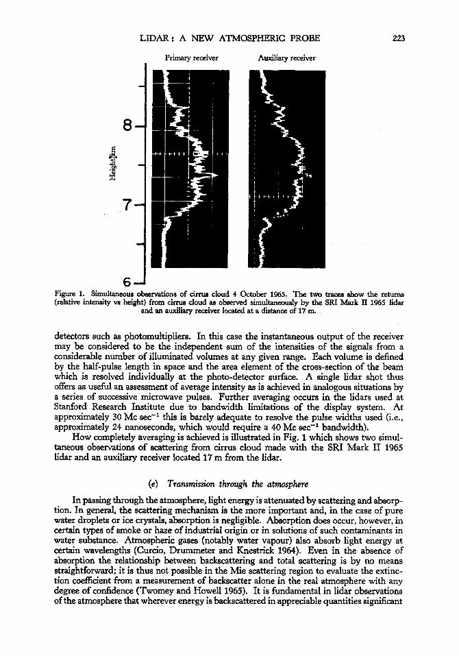
6-1 Figure 1. Simultaneous observations of cirrw cloud 4 October 1965. The two traces show the returns (relative intensity vs height) from cirrus cloud observed s~ultaneously by the SRI hhrk I1 1965 lidar
and an auxiliary receiver located at a distance of 17 m
detectors such as photomultipliers. In this case the instantaneous output of the receiver may be considered to be the independent sum of the intensities of the signals from a considerable number of illuminated volumes at any given range. Each volume is defined by the half-pulse length in space and the area element of the cross-section of the beam which is resolved individually at the photo-detector surface. A single lidar shot thus offers as useful an assessment of average intensity as is achieved in analogous situations by a series of successive microwave pulses. Further averaging occurs in the lidars used at Stanford Research Institute due to bandwidth limitations of the display system. At approximately 30 Mc sec-l this is barely adequate to resolve the pulse widths used (i.e., approximately 24 nanoseconds, which would require a 40 Mc sec-l bandwidth).
How completely averaging is achieved is illustrated in Fig. 1 which shows two simul- taneous observations of scattering from cirrus cloud made with the SRI Mark I1 1965 lidar and an auxiliary receiver located 17 m from the lidar.
(e) Transmission through the atmosphere
In passing through the atmosphere, light energy is attenuated by scattering and absorp- tion. In general, the scattering mechanism is the more important and, in the case of pure water droplets or ice crystals, absorption is negligible. Absorption does occur, however, in certain types of smoke or haze of industrial origin or in solutions of such contaminants in water substance. Atmospheric gases (notably water vapour) also absorb light energy at certain wavelengths (Curcio, Drummeter and Knestrick 1964). Even in the absence of absorption the relationship between backscattering and total scattering is by no means straightforward: it is thus not possible in the Mie scattering region to evaluate the extinc- tion coefficient from a measurement of backscatter alone in the real atmosphere with any degree of confidence (Twomey and Howell 1965). It is fundamental in lidar observations of the atmosphere that wherever energy is backscattered in appreciable quantities significant

224 R. T. H. COLLIS
attenuation will also occur and the resultant signal will be a compound of two factors. In this respect lidar observations resemble radar observations of precipitation at millimetre wavelengths rather than at the longer wavelengths normally used in weather radars at which attenuation is often negligible.
Light energy is also refracted in passing through the atmosphere. Inhomogeneities in density, which are always present, disrupt the uniformity of the laser beam by differen- tial refraction, which causes local concentrations of energy with additional effects due to constructive and destructive interference of the partially coherent light (Consortini, Ronchi, Scheggi and Toraldo di Francia 1963). This phenomenon, which is a vital factor in the use of the laser in communications, may be ignored in the basic lidar application, but must be considered in more advanced concepts.
3. THE INFORMATION CONTENT OF LIDAR SIGNALS FROM THE ATMOSPHERE
(a ) Basic capability
The basic lidar observation consists of an evaluation of received signal intensity in terms of range and direction. Although it is often not possible to evaluate intensity information in absolute terms, in many cases the information is unequivocal and of direct value. This is particularly so where the lidar beam encounters strongly scattering targets after passing through relatively clear air, as is the case with clouds. Again, minor variations of backscattering in range are immediately obvious, and serve to reveal haze layers and gross inhomogeneities in what appears to the eye to be clear air. In continuously scattering atmospheres analysis of the rate of change of signal intensity, dP,/dr, can reveal homo- geneity of the atmosphere over increments of range, for it will be seen that regardless of their relation one to another, if the volume backscattering function Fls0 and the coefficient of extinction, u, do not change with range, the plot of P, vs r will be a regular exponential curve. Where such homogeneity is apparent, the extinction coefficient u can be evaluated from analysis of this curve.
Even in inhomogeneous conditions, for example in penetrating clouds, the change of signal intensity with range can readily be interpreted qualitatively and used to deduce the nature of variation in particle concentration.
The rate at which data is collected is important, The resolution of observations in time is, of course, dependent upon their frequency, whilst high pulse repetition rates are necessary to produce useful scanning systems.
These basic capabilities are very considerable, for they make it possible to study, remotely, in three dimensions many atmospheric phenomena that hitherto could only be observed grossly or examined piecemeal.
(b) Advanced concepts
Beyond these basic capabilities other possibilities of acquiring information exist. Exploitation of polarization characteristics or the use of spectrographic techniques (Goyer and Watson 1963) with simultaneous observations at different wavelengths are promising and experimental programmes to investigate these approaches are in progress at Stanford Research Institute.
Other possibilities that are being considered elsewhere are the use of coherent systems to detect Doppler shifts (at the carrier or modulated frequency) due to relative motion of the atmosphere, particularly that due to turbulence, or the recovery of similar informa- tion from a consideration of the pulse-by-pulse fluctuation in incoherent systems. These prospects, while undoubtedly exciting, involve formidable problems, of which the engi- neering and instrumental aspects are by no means the least.

LIDAR: A NEW ATMOSPHERIC PROBE 225
Any hope of detecting turbulent eddies directly by variations in backscattered signals from the gaseous atmosphere appears ill-founded. As noted, backscattering by dielectric inhomogeneities is too small to be worth serious consideration, while variations in molecular backscatter from the gaseous atmosphere resulting from discontinuities of pressure or temperature are likewise insignificant and would in any case be impossible to distinguish from variations in scattering due to particulate matter.
4. ATMOSPHERIC OBSERVATIONS WITH LIDAR
An exploratory programme to investigate the use of lidar has been carried on at Stanford Research Institute since 1963 and a wide variety of atmospheric targets have been observed. Many of these observations have been described in detail elsewhere. The basic capability of lidar in atmospheric applications is here summarized with illustrations.
(a) clouds (cob 1965)
All types of clouds have been observed by night and day, and through rain. Of particular interest is the ability of the lidar to resolve fine-scale structure (see Fig. 1, for example) and to distinguish multiple layers. Again, lidar can detect concentrations of cloud particles too tenuous to be visible to the eye. Echoes showing detailed structure are commonly observed from apparently clear areas of the sky at levels at which no visible cirrus is present. Sub-visible’ phases of stratus clouds are shown in a sequence of observations in Fig. 2. These observations were made as the cloud layer dissipated and show a continuity which was not apparent visually. The visible cloud in Observation I is shown to have a base at 550 m with a minor return at 500 m. Attenuation by this cloud was sufficient to obscure echoes from a layer at 700 m, which are seen weakly in Observations I1 to V inclusive when the cloud became invisible to the eye. The lower layer shown in these observations weakens also, and is no longer detected in Observation VII.
1107.4 1108.3 1108.8 1109.3 1109.8 1110.3 1110.8 PACIFIC DAYLIGHT TIME
COINCIDENT VISUAL OBSERVATIONS MADE THROUGH LIDAR’S AIMING TELESCOPE P IX
BLUE SKY
I
CLOUDS
Figure 2. Dissipating low stratus cloud, 29 September 1964. Series of vertical lidar observations (Mark I 1964) as layer of low stratus dissipated. Visibility at surface 9 km. Clear skies as stratus cleared from west.
Coincidental visual observations made through lidar’s aiming telescopes.

226
-8 ir
R. T. H. COLLIS
(VISIBILITY I N LOCALITY ESTIMATED AS 13km)
Q = 0.5 km-' VM = 7.8 krn a'
300 600 900 1200 a - SLANT RANGE - m
114 I PST 4 FEE 64 MENLO PARK €LEV 10' 3 i2
VM = 12 km
(VISIBILITY ESTIMATED AS lOkm I
0.1 I I I I 300 600 900 1200
SLANT RANGE - m 1050 PST 15SEPT64 HALF MOON 8AY E L N 5*
Figure 3. Evaluation of the coefficient of extinction from observations in elight haze with SRI Mark I 1964 lidar.
Note : Transmitter and receiver beams were not fully convergent before 600 m. o = extinction coefKuent VM = meteorological range
(b) Fog and haze In penetrating strongly scattering atmospheres such as haze or fog (or cloud), the
lidar return shows the combined effects of scattering and attenuation described in Section 3. Returns from such atmospheres often show considerable patchiness, but where homo- geneity is apparent, the extinction coefficient may be deduced, Fig. 3 shows, for example, plots of the logarithm of the intensity (range corrected) versus range for typical hazes. From Eq. (l), d log P, P/dr = - 2u if u and plea are constant with range, and the slopes of the curves shown thus yield u, from which transmissivity or meteorological range can be derived.
(c) ' Clear air ' The sensitivity and resolution of even the early lidars used are such that returns are
regularly and consistently obtained from apparently clear air in good visibility. At close range, echoes such as are seen between 200 m and the ' cloud ' echoes in Fig, 2 are typical and may be analysed in the way illustrated in Fig. 3. (Because the transmitter and receiver beams do not intersect straight away, the returns are not obtained at close range [i.e., less than 200 m in this case] unless the instrument is specially adjusted). Discontinuities in the returns can reveal the juxtaposition of different types of atmosphere. In Fig. 2, for example, the marked reduction in signal intensity above 725 m is due to the reduced backscattering coefficient of the cleaner air above the low-level inversion. Stratification of this type and the presence of haze layers in clear air can readily be related to the thermal and humidity profiles both at low levels (Collis, Fernald and Ligda 1964) and much higher. Discontinuities in the scattering and attenuation coefficients can also be related to wind shears throughout the troposphere. Non-stratified inhomogeneities such as occur at the interface of a sea breeze, have also been observed (Collis and Ligda 1964).
LIDAR: A NEW ATMOSPHERIC PROBE 227
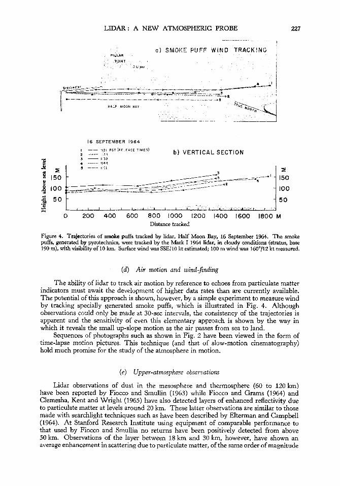
a ) SMOKE PUFF W I N D TRACKING ~
16 SEPTEMBER 1964
I -- I I P I P S T ( R E L E A S E T I M E S ) 2 1133 - 3 - 1139 4 ,-- . I144 5 --- 1151
b ) VERTICAL SECTION
2 1 150
- t / - - - - 7 5 5 __/-----
/----y----w/--- *--- ______.---*---
lr - - - - - - - *-Q- 8 100 ___.. y--.&c.ry&=- _.__.._-- ------*--
3 5 0 ." 8
0 200 400 600 800 1000 1200 1400 1600 1800 M Distance tracked
Figure 4. Trajectories of smoke puffs tracked by lidar, Half Moon Bay, 16 September 1964. The smoke puffs, generated by pyrotechnics, were tracked by the Mark I 1964 lidar, in cloudy conditions (stratus, base 190 m), with visibility of 10 km. Surface wind was SSE/10 kt estimated; 100 m wind was 160°/12 kt measured.
(d) Air motion and wind-$nding
The ability of lidar to track air motion by reference to echoes from particulate matter indicators must await the development of higher data rates than are currently available. The potential of this approach is shown, however, by a simple experiment to measure wind by tracking specially generated smoke puffs, which is illustrated in Fig. 4. Although observations could only be made at 30-sec intervals, the consistency of the trajectories is apparent and the sensitivity of even this elementary approach is shown by the way in which it reveals the small up-slope motion as the air passes from sea to land.
Sequences of photographs such as shown in Fig. 2 have been viewed in the form of time-lapse motion pictures. This technique (and that of slow-motion cinematography) hold much promise for the study of the atmosphere in motion.
(e) Upper-atmosphere observations
Lidar observations of dust in the mesosphere and thermosphere (GO to 120 km) have been reported by Fiocco and Smullin (1963) while Fiocco and Grams (1964) and Clemesha, Kent and Wright (1965) have also detected layers of enhanced reflectivity due to particulate matter at levels around 20 km. These latter observations are similar to those made with searchlight techniques such as have been described by Elterman and Campbell (1964). At Stanford Research Institute using equipment of comparable performance to that used by Fiocco and Smullin no returns have been positively detected from above 50 km. Observations of the layer between 18 km and 30 km, however, have shown an average enhancement in scattering due to particulate matter, of the same order of magnitude

228 R. T. H. COLLIS
noted by others (ie., by a factor of as much as 1.7 over that expected from a purely gaseous atmosphere). These observations show, in addition, that particulate matter concentrations at these levels can have a remarkably detailed patchy or layered structure similar to that observed in stable conditions in the clear lower atmosphere (Collis and Ligda 1966).
5. LIDAR APPLICATIONS
The basic capability of lidar for making atmospheric observations and measurements has obvious application in many areas of atmospheric research and operational meteorology. Further technological development is necessary, however, before lidar can readily be used in the latter role. In particular, there is a need for a more convenient system of displaying data than the current rapid-process photography of an oscilloscope and higher pulse repetition rates are needed to provide greater time resolution and the possibility of scanning extended volumes of space.
In some types of observation lidar merely extends the capability of earlier optical probing techniques. This is true, for example, of cloud-base measurement or the detection of scattering layers in the high atmosphere. In such areas, however, the increased resolu- tion and sensitivity of lidar gives rise to what amounts to a new capability. Thus, for example, lidar makes it possible to study the incidence and fine-scale structure of even very tenuous cirrus clouds or to distinguish the variable structure of stratospheric dust layers. In addition, the enhanced performance of lidar permits the assessment of density gradients in penetrating cloud, fog or haze. The most dramatic advance achieved by lidar, however, is the extension of optical scattering or radar techniques to the detection and delineation of concentrations of particulate matter in the lower atmosphere in what for long has been accepted, for practical purposes, as clear air.
This has made apparent a structure and stratification which have not previously been observed remotely or in such detail. Although isolated soundings are of obvious value, a specially attractive possibility which will result from the development of high-data-rate systems, is that of viewing the clear air in motion.
The capability of being able to distinguish such variations in clear air, whether statically or dynamically, opens up new resources in remotely probing the atmosphere which have application in meteorological research, weather analysis and forecasting, air pollution study and control, and, possibly, in problems such as the detection of clear air turbulence as it affects aircraft (Collis 1964).
In addition to such basic applications of lidar in atmospheric observation, the potential of more sophisticated techniques outlined in Section 3 (b) should be noted.
6. CONCLUSIONS Lidar is a new tool of great promise for atmospheric studies. Although having antece-
dents in optical instrumentation, it is best considered a logical extension of weather radar that makes it possible to trace the atmosphere’s particulate constituents in a much smaller size range than is possible at centimetric or even millimetric wavelengths. Like weather radar, lidar may be expected to open up new dimensions of perception in atmospheric physics and meteorology.
ACKNOWLEDGMENTS The experimental lidar programme at Stanford Research Institute was initiated and is
directed by Dr. M. G. H. Ligda, Manager of the Aerophysics Laboratory. The equipment, which includes components lent by Lear Siegler Corporation, was developed in the Elec- tromagnetic Techniques Laboratory under the direction of Dr. R. C. Honey. The Office of Naval Research (under Contract No. 4471 (OO)), Lear Siegler Corporation and Stanford Research Institute sponsored the research on which this paper is based. The author wishes especially to thank Messrs. J. W. Davies and F. G. Fernald for their assistance and contributions in the preparation of this paper.
LIDAR: A NEW ATMOSPHERIC PROBE 229
Bureau, R. Clemesha, B. R., Kent, G. S.
Collis, R. T. H.
Collis, R. T. H., Fernald, F. G.
Collis, R T. H. and Ligda, M. G. H.
Consortini, A,, Ronchi, L., Scheggi, A. M. and Toraldo di Francia, G.
Curcio, J. A., Drummeter, L. F. and Knestrick, G. L.
Davies, J. W. Elterman, L.
Elterman, L. and Campbell, A. B. Fiocco, E. and Grams, G. Fiocco, G. and Smullin, L. 0. Friedland, S. S., Katzenstein, J.,
Goyer, G. G. and Watson, R. Horman, M. H. Lhermitte, R. M. Ligda, M. G. H. Middleton, W. E. K. and
Spilhaus, A. F. Munick, R. J. Perlat, A. and Petit, M. Twomey, S. and Howell, H. B.
and Wright, R. W. H.
and Ligda, M. G. H.
Sherman, J. and Zatzick, M. R.
1946 1965
1964 1965 1964
1964 1966 1963
1964
1966 1964
1964 1964 1963 1.956
1963 1961 1960 1964 1953
1964 1961 1965
REFERENCES
Me'te'orologie, 3, p. 292. Sci. Rep., University of West Indies Contract AF-AFOSR
Astronautics and Aeronautics, p. 52. Science, 149, p. 978. Nature, 203, p. 1274.
Ibid., p. 508. To be published, J. Atmos. Sci. A k a Frequenza (Milan), 32, p. 178.
616-64, p. 38.
Appl. Opt., 3, p. 1401.
To be published, J, Geophys. Res. Environmental Research Papers, Air Force Cambridge Res.
J. Atmor. Sci., 21, p. 457. Ibid., 21, p. 323. Nature, 199, p. 1275. J. Geophys. Res., 61, p. 415.
Bull. Amer. Met. SOC., 44, p. 564. J. Opt. SOC. Amer., 51, p. 681. Proc. 8th Weather Radar Conference, Amer. Met. SOC., p. 263. Proc. 11th Weather Radar Conference, h e r . Met. SOC., p. 482. Met. Instruments, Univ. of Toronto Press, p. 208.
New York Mtg. Rep., Opt. SOC., America, p. 28.. Mesures en Me't6orologie, Gauthiers-Villars, .Paris, p. 195. Appl. Opt., 4, p. 501.
Lab., AFCRL-64-740.
APPENDIX I
STANFORD RESEARCH INSTITUTE (SRI) LIDARS
Component
Transmitter Laser
Q-switch
Pulse length
Peak power
Optics
Beam-width
P.R.F.
Mark I 1963 Mark I1 1963 Mark I 1964 Mark I1 1965
3 x &in. 90" C-axis ruby crystal, C-axis ruby crystal, C-axis ruby crystal, 60" orientation ruby transparent and transparent and Brewster angle ends, crystal, rooftop and semi-reflecting semi-reflecting uncoated Brewster angle ends coatings on flat ends coatings on flat ends
Rotating prism Rotating prism Uranyf glass (UO,++) Rotating prism
30 nanoseconds 30 nanoseconds 24 nanoseconds 30 nanoseconds
3 x t in . 90" 3 x &in. 900 (Two)' 3 x 4 in.
uncoated
5 mw 5 mw 10 mw 10 mw
None Refractor, Refractor, 129 in. Newtonian 4 in. aperture 4 in. aperture reflector, telescope
Approximately 0.03" Approximately 0.03" Approximately O*0lo 0.5"
1 per minute 1 per minute 2 per minute 2 per minute (each laser)
230 R. T. H. COLLIS
APPENDIX I (continued)
STANFORD RESEARCH INSTITUTE (SRI) LIDARS
Component
Receiver Photomultiplier
Optics
Beam-width
Band-pass
D i s p 1 a y
Mark1 1963 Mark I1 1963 Mark I 1964 Mark I1 1965
10-stage R.C.A. 10-stage R.C.A. 14-stage R.C.A. (Two)* 16-stage I.T.T. type 7326 type 7326 type 7265 TyPe FW130G S-20
cathode
4 inch aperture 4 inch aperture 4 inch aperture 12& in. Newtonian aerial camera aerial camera aerial camera reflector telescope objective with objective with objective with adjustable field stop adjustable field stop adjustable field stop
0.07" d n . to 0.07" min. to 0.07" min. to 0.01" min. to 0.8" ma. 0.8" max. 0.8" max. 0.7" max.
Approx. 20 A Approx. 20A Approx. 1 7 A Approx. 4 A
Tektronix 555 Tektronix 555 Tektronix 555 Tektronix 555 dual-beam dual-beam dual- beam dual- beam oscilloscope oscilloscope oscilloscope oscilloscope and
ranged-gated threshold discriminator and digital counter
Mark I1 1965 : This equipment comprises two separate transmitter and receiver systems capable of Provision is operating successively through the same optical system at intervals as short as 0.75 millisec
made for varying the polarization of the transmitted energy and analysing the received energy.