libya - bsu.edu.ly
TRANSCRIPT


TH
E S
TU
DE
NT
NA
ME
BA
CH
EL
OR
20
18
Libya Ministry of Higher Education Bright Star University – Braga
Bright Star University – Braga
Faculty Of Technical Engineering Department of Chemical Engineering
AMMONIUM NITRATE
AN
By
Sharefa Hamad Mohammed 21152878
Hana Abduallah Idris 21152899
Hana Imhumd Rashed 21152876
Mabroka Abdalhamid Bushnaf 211521037
Laylaa Alsalihin Iihmudh 21161157
Supervised By
Abdalhamid Almisri
DEGREE OF BACHELOR IN CHEMICAL ENGINEERING
FACULTY OF TECHNICAL ENGINEERING
CODE OF PROJECT ( CHE 2017 049F108 )

i
AMMONIUM NITRATE
By:
Sharefa Hamad Mohammed 21152878
Hana Abduallah Idris 21152899
Hana Imhumd Rashed 21152876
Mabroka Abdalhamid Bushnaf 211521037
Laylaa Alsalihin Ihmudh 21161157
Supervised by:
Abdalhmid Almisri
Project Report Submitted as Partial Fulfillment of the Requirements for the Degree of Bachelor in Chemical Engineering
Month, 2018

ii
ABSTRACT
A Plant is to be designed for production of (22590 ton/year) of crystalline
Ammonium Nitrate coming With nitric acid liquid ammonia. The product is
required in dry crystalline condition containing (0.1) percent moisture, and should
be incorporated in the design.
Nitrate acid is available at concentration (47.5% W) storage for (48 hours) supply
is required. Liquid ammonia under pressure, (99% W NH3) containing (1%) water,
is available and storage is also required at least for this for (48 hours) supply. The
crystals are withdrawn as (30%) slurry.
Then, the centrifuged in batch centrifuged discharged with (2%W) adhering
moisture onto a conveyer which feeds them continuously into a counter current
rotary air dryer, fed with air at (250ºF). The effluent air passes through a dust
collection system. The dried product contains (0.1%) moisture is sieved and the
undersize product is recycled together with the dust from the drier to the
evaporator stage. It can be assumed that these recycle streams amount to (0.5 and
0.3 ton/day) , respectively. Losses on the process will be assessed at (0.3 ton/day)
and may be assumed to occur at the centrifugal stage.

iii
DEDICATION
بدأنا بأكثر من يد وكافحنا بعزم وجد وها نحن اليوم والحمد لله نطوي سهر الليالي وتعب السنين..
إلى منارة العلم والعالمين إلى سيد الخلق إمام المرسلين...إلى الأمي الذي علم المتعلمين...
"رسول الله صلى الله عليه وسلم"
نوراً لي في طريقي..... إلى من كان رضاها زاداً لي في حياتي... ودعواتها
"أمي الغالية"
إلى الذي علمني كيف أمسك قلمي لأكتب أول حرف الهجاء...إلى عاقد الحاجبين مبتسماً ليخفي تعبه...إلى من
كان المشي خلفه افتخاراً.....
"أبي العزيز"
إلى الشموع التي تنير دربي...إلى السعادة التي تملأ حياتي.....
"أخوتي وأخواتي"
لى من عرفت معهم معنى المحبة والأخوة...إلى من شاركوني أسعد اللحظات ونقشت معهم على مر السنين إ
أجمل الذكريات.....
"أصدقائي"
إلى كل من علمني حرفاً وأنار بالعلم طريقي.....
"أستاذي الفاضل"
إليكم جميعاً اهدي ثمرة جهدي
. . . . . .طالبات المشروع

iv
ACKNOWLEDGEMENTS
I would like to express my appreciation to my supervisor, ( Abdalhmid Almisri) who has
cheerfully answered my queries, provided me with materials, checked my examples, assisted me
in a myriad ways with the writing and helpfully commented on earlier drafts of this project. Also,
I am also very grateful to my friends, family for their good humor and support throughout the
production of this project

v
APPROVAL
This project report is submitted to the Faculty of Technical Engineering, Bright Star University –
Braga, and has been accepted as partial fulfillment of the requirement for the degree of bachelor
in Chemical Engineering. The members of the Examination Committee are as follows:
________________________________________
Supervisor
Abdalhmid Almisri
Department of Chemical Engineering
Faculty of Technical Engineering
Bright Star University – Braga
____________________________________________
Examiner 1
The examiner name
Department of Ashraf Adam Engineering
Faculty of Technical Engineering
Bright Star University – Braga
____________________________________________
Examiner 2
The examiner name
Department of Anas al-Abani Engineering
Faculty of Technical Engineering
Bright Star University – Braga

vi
DECLARATION
I hereby declare that the project report is my original work except for quotations and citations,
which have been duly acknowledged. I also declare that it has not been previously, and is not
concurrently, submitted for any other degree at Bright Star University – Braga or at any other
institution.
With best regarding of project prepared students:
Sharefa Hamad Mohammed 21152878
Hana Abduallah Idris 21152899
Hana Imhumd Rashed 21152876
Mabroka Abdalhamid Bushnaf 211521037
Laylaa Alsalihin Ihmudh 21161157
TABLE OF CONTENTS

vii
ABSTRACT ii
DEDICATION iv
ACKNOWLEDGEMENTS iv
APPROVAL v
DECLARATION vi
LIST OF TABLES x
LIST OF FIGURES xii
NOMENCLATURES xii
CHAPTER 1: INTRODUCTION
1.1 INTRODUCTION 1
1.2 Problem Statement 2
1.3 Description of Proess 3
1.4 Data to be used in design 3
1.5 Production 4
1.6 Ammonium Nitrate Process 4
1.6.1 Crystalline phases 6
1.6.2 Reaction 6
1.7 Fertilizer 7
CHAPTER 2:MATERIAL AND ENERGY BALANCE
2.1 The Material Balance 9
2.1.1 Material Balance of Reactor 9
2.1.2 Material Balance around the Dryer 11
2.1.3 Overall Material Balance 13
2.1.4 Material Balance around the Washing Tower 14
2.1.5 Ammonium Nitrate Material Balance 14
2.1.6 Material Balance around the Crystallizer 16
2.1.7 Material Balance around the Evaporator 17
2.1.8 Material Balance around Branches 18

viii
2.1.9 Overall Material Balance around the 18
2.2 The Energy Balance 20
2.2.1 Heat Balance around Ammonia Evaporator 20
2.2.2 Latent Heat for steam at 11bar 21
2.2.3 Heat Balance around Nitric Acid Heater 22
2.2.4 Heat Balance around the Reactor 22
2.2.5 Heat Balance around the Evaporator 25
2.2.6 Heat Balance around the Crystallizer to Find Crystallizer Temperature 27
2.2.7 Heat Balance around the Dryer 30
CHAPTER 3:PROCESS DESIGN OF EVAPORATOR
3.1 Calculation Heat Transfer Surface Area 32
3.2 Calculation The Overall Heat Transfer 32
3.3 Use One Shell and One Tube Pass 35
3.3.1 Using a Split ring floating head 35
3.3.2 Pressure Drop Inside the Tubes 36
3.4 Process Design of the Vapour- Liquid Separator 37
3.5 Process Design 37
3.6 Choosing Pitch of Heat Exchanger 43
3.7 Calculation Coefficient of Overall Heat Transfer 46
3.8 Calculation of Pressure Drop Inside Heat Exchanger 47
3.8.1 Pressure Drop Tube Side 47
3.8.2 Pressure Drop Shell Side 48
3.9 Mechanical Design for Separator 48
3.9.1 Thickness of the Shell 48
3.9.2 Design for the Atorispherical dished 50
3.9.3 Design of conical closure 50
3.10 Calculation the Nozzle Size on Wall of the Separator 51

ix
3.11 The Velocity through Outlet of the Separator 52
CHAPTER 4:INSTRUMENTATION AND CONTROL
4.1 Instruments 54
4.1.1 Instrumentation and control objectives 54
4.1.2 Guide Rules 55
4.2 Typical control systems 56
4.2.1 Level Control 56
4.2.2 Pressure Control 56
4.2.3 Ratio Control 57
4.2.4 Flow Control 57
4.2.5 Temperature Control 58
4.3 Incorporation of the Controllers 59
CHAPTER 5: SAFETY AND ENVIRONMENTAL
5.1 Introduction 61
5.2 Task Evaluation 61
5.3 Chemical Storage 61
5.4 Emergencies and Spills 62
5.5 Housekeeping 62
5.6 MSDS Information 63
5.7 Chemical Users Information 64
5.8 Chemical Reaction Information 64
5.9 Control Measures 64
5.10 Health Hazards 64
5.11 Safety and Environment Precautions 65
5.11.1 Acute Health Effects 65
5.11.2 Long-Term Health Effects 66
CHAPTER 6: MATERIAL OF COST
6.1 Introduction to Material of Construction 67

x
6.2 The Sizing of the Plant 67
CHAPTER 7: PLANT LAYOUT AND CONCLUSION
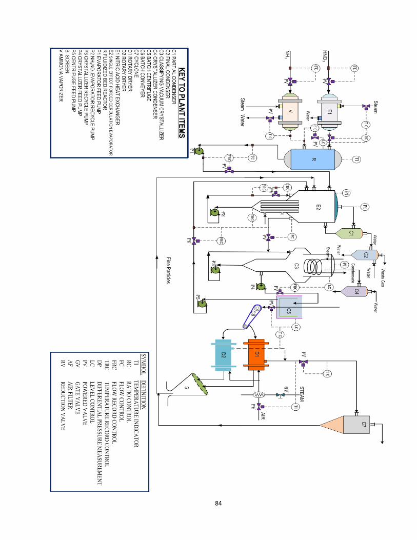
7.1 Plant layout 84
7.2 Conclusion 86
REFERENCES 87
APPENDICES
Appendix A
LIST OF TABLES

xi
Table.1.1: Data to be used in design .................................................................................................
Table.1.2: Crystalline Phases……………………………………………………………………….
Table.2.1.1: Reactor Inlet and Outlet Components………………….……………………………..
Table.2.1.2: Material Balance Around the Dryer…………………………………………………..
Table.2.1.3: Material Balance Around Washing Tower……………………………………………
Table.2.1.4: Material Balance Around Crystallizer………………………………………………
Table.2.1.5: Material Balance Around Evaporator…………………………………………………
Table.3.1: Data of Temperature / Growth Rate Relation…………………………………………...
Table.4.1: Some Symbols Used in the Control Systems…………………………………………...
Table.5.1: Exposure and Hazard Level……………………………………………………………..
Table.5.2: Type of Effect and Effect Level………………………………………………………...
Table.6.1: Sizing of Ammonia Vaporizer…………………………………………………………..
Table.6.2: Sizing of Nitric Acid Heat Exchanger…………………………………………………
Table.6.3: Sizing of Reactor……………………………………………………………………….
Table.6.4: Sizing of Evaporator……………………………………………………………………
Table.6.5: Sizing of Crystallizer……………………………………………………………………
Table.6.6: Sizing of Ammonium Nitrate Dryer……………………………………………………
LIST OF FIGURES
Figure 1.1: Ammonium Nitrate ; Chemical fromula and White Crystalline ....................................
Figure 1.2: Simplified Flowchart for the Stengel Process for Ammonium Nitrate……………….

xii
Figure 2.1.1: Material Balance Around the Reactor .........................................................................
Figure 2.1.2: Material Balance Around the Dryer ............................................................................
Figure 2.1.3: Material Balance Around the Washing Tower………………………………………
Figure 2.1.4: Material Balance Around the Crystallizer…………………………………………...
Figure 2.1.5: Material Balance Around the Evaporator…………………………………………….
Figure 2.1.6: Plant of Ammonium Nitrate…………………………………………………………
Figure 2.2.1: Energy Balance Around Ammonia Evaporator…………………………………….
Figure 2.2.2: Energy Balance Around Nitric Acid Heater…………………………………………
Figure 2.2.3: Heat Balance Around the Evaporator……………………………………………….
Figure 2.2.4: The relation between Solubility versus Temperature for Ammonium Nitrate……..
Figure 3.1: Growth Rate of Ammonium Nitrate Crystals With Temperature……………………
Figure 3.2: Forced Circulation Evaporator With One pass Vertical Separator……………………
Figure 4.1: A typical arrangement for the Level Control …………………………………………
Figure 4.2: A typical arrangement for the Pressure Control………………………………………
Figure 4.3: A typical Scheme for ratio Control…………………………………………………….
Figure 4.4: A typical arrangement for the Flow Control…………………………………………..
Figure 4.5: A typical arrangement for Temperature Control………………………………………
Figure 4.6: Flow Scheme of Typical process with Controllers…………………………………….
Figure 7.1: Plant Diagrams…………………………………………………………………………
NOMENCLATURES
Cp
Heat Capacity
KJ/Kg .Cº

xiii
T Temperature Cº
ΔH Enthalpy Change KJ/hr
M MASS Flow Rate Kg/hr
ρ density Kg/m3
U Overall Heat Transfer
Coefficient W/m2.Cº
A Total Heat transfer area m2
ΔTlm Mean Temperature Difference Cº
do Outside Tube Diameter mm
di inside Tube Diameter mm
V Velocity m/s
L Tube length m

xiv
hi Tube side film coefficient w/m3.ºc
h0 Shell side film coefficient w/m3.ºc
Gs Shell side mass velocity Ib/hr.ft2
μ Shell side fluid viscosity Ib/hr.ft
Kf Shell side fluid thermal But/Ib .ºF
Np Number of passes
Jf B asic friction factor
ΔPt tube –side pressure drop N/m or atm
Ds Shell diameter m
De Equivalent diameter m

1
CHAPTER 1
INTRODUCTION
1.1 . Introduction
The chemical compound Ammonium Nitrate, the nitrate salt of ammonium, has the
chemical formula NH4NO3, simplified to N2H4O3. It is a white crystalline (Fig. 1-1) solid
which is highly soluble in water. It is predominantly used in agriculture as a high-nitrogen
fertilizer. The compound is used as explosives in mining, and also sometimes in improvised
explosive devices. It is the main component of (ANFO), a popular explosive, which
accounts for (80%) explosives used in North America. It is used in instant cold packs, as
hydrating the salt is an endothermic process.
Ammonium Nitrate is found as a natural mineral (ammonia nitrate; the ammonium
analogue of saltpetre and other nitrate minerals such as sodium nitrate) in the driest regions
of the Atacama Desert in Chile, often as a crust on the ground and/or in conjunction with
other nitrate, chlorate, iodate, and halide minerals. Ammonium Nitrate was mined there in
the past, but virtually (100%) of the chemical now used is synthetic.
Fig. 1-1 :Ammonium Nitrate ; chemical formula and white crystalline

2
1.2. Statement of the problem
A plant is to be designed for production of (22590 tons /year) of crystalline Ammonium
Nitrate coming with nitric acid and liquid ammonia.
The product is required in dry crystalline condition containing (0.1) percent moisture, and
should have no allowance for maintenance shut-down and should be incorporated in the
design.
Nitrate acid is available at a concentration (47.5%W) storage for (48 hours) supply is
required. Liquid ammonia under pressure , (99%W NH3) containing (1%) water, is
available and storage is also required for this for (48 hours) supply. Other services are:
Steam at (150 Ib/in2 (psi) gauge saturated.
Water at (15°C) , (80 Ib/in2 (psi)) gauge.
Electricity (440V) , 3- phase , A.C 50 Cycle / second (50HZ).
The crystals are withdrawn as (30%) slurry. Then is centrifuged in batch centrifuges.
Discharged with 2%W adhering moisture onto a conveyer which feeds them continuously
into a counter current rotary air dryer, fed with air at (250°F). The effluent air passes
through a dust collection system. The dried product contains (0.1%) moisture is sieved and
the undersize product is recycled together with the dust from the drier to the evaporator
stage. It can be assumed that these recycle streams amount to (0.5 and 0.3 ton/day) ,
respectively. Losses on the process will be assessed at (0.3 ton/day) and may be assumed to
occur at the centrifugal stage.
Ammonium Nitrate can also be made via metathesis reactions:

3
1.3. Description of process
Ammonia gas and Nitric acid are reacted to give a solution of Ammonium Nitrate which is
concentrated then cooled in an evaporative crystallizer. The centrifuged and the resulting
crystals dried and sieved, the liquid ammonia from the storage at (120 psig) pressure at
(60°F), is vaporized in a steam heated heat exchanger and passed into the reactor together
with the nitric acid. The exothermic reaction raises the temperature to boiling point and
evaporates part of the water forming a hot concentrated solution of Ammonium Nitrate .
The reactor is designed to prevent undue entrainment of liquid in the water- vapor off take
and has adequate volume to allow the reaction to proceed smoothly at a controlled (pH),
which must be on the alkaline side for safety reasons. The resultant Ammonium Nitrate
solution is concentrated to (77% w) in a single effect , forced circulation vacuum
evaporator and is fed to a classifying vacuum crystallizer . The crystallizer is designed to
allow the growth of crystals to the required size and a fines separator is provided to allow
for the removal and solution of excess nuclei.
1.4. Data to be used in design A) Solubility of Ammonium Nitrate in Water
Temperature(°C) gm NH4NO3 / 100gm saturated solution 00.0 54.2
12.2 60.0
20.0 65.6
25.0 68.1
30.0 70.3
35.0 72.5
40.0 74.3

4
1.5. Production The industrial production of Ammonium Nitrate entails the acid-base reaction of
ammonia with nitric acid:
Ammonia is used in its anhydrous form (i.e. gas form) and the nitric acid is concentrated.
This reaction is violent owing to its high exothermic nature.After the solution is formed,
typically at about (83%) concentration, the excess water is evaporated to an Ammonium
Nitrate (AN) content of (95% to 99.9%) concentration (AN melt), depending on grade. The
AN melt is then made into "prills" or small beads in a spray tower, or into granules by
spraying and tumbling in a rotating drum.
The prills or granules may be further dried, cooled, and then coated to prevent caking.
These prills or granules are the typical AN products in commerce.
The ammonia required for this process is obtained by the Haber process from nitrogen and
hydrogen. Ammonia produced by the Haber process is oxidized to nitric acid. Another
production method is used in the so-called Odd process.(Sodium sulfate is removed by
lowering the temperature of the mixture. Since sodium sulfate is much less water-soluble
than Ammonium Nitrate, it precipitates, and may be filtered off. For the reaction with
calcium nitrate, the calcium sulfate generated is quite insoluble, even at room temperature.
1.6. Ammonium Nitrate Process Ammonium Nitrate is a very important nitrogenous fertilizer because of its high nitrogen
content (33%), the simplicity and cheapness of its manufacture , and its valuable
combination of quick acting nitrate and slower acting ammoniacal nitrogen. Its tendency to
cake on storage reduced its acceptability at first but proper granulation, the addition of
antihygroscopic agent, better packaging have largely remedied this problem. Most
commercial and many military explosives contain cheap Ammonium Nitrate as the major
explosive ingredient.

5
Ammonium Nitrate is difficult to detonate, but, sensitized with oil or mixed with other
explosive material, it can be detonated with a large booster primer.
Ammonium Nitrate mixture are “permissibles” that is, permitted for use in coal mines
where combustible vapors may be encountered. The use of explosive in mines and quarries
provide a large and continuing market. Amotal is a mixture of (TNT) and granular
Ammonium Nitrate (AN). This is the major conventional military explosive. On explosive
decomposition, AN rapidly and violently decomposes to form elemental nitrogen.
Under different conditions, (i.e., ), it is safely decomposed to form an
aesthetic nitrous oxide. This is the commercial method of preparation.
Ammonium Nitrate is made by reacting nitric acid ( made by oxidizing ammonia)with
ammonia:
If properly proportioned and preheated, the reaction can be run continuously to produce
molten Ammonium Nitrate containing very little water (1 to 5%) which can be formed into
small spheres (preills) by dropping the reaction product through a shot tower or into flakes
by cooling it on belts or drums. By fluidized bed treatment , it is possible to obtain a dry
granular material as product. Batch processes have also been used, but the labor and
equipment costs are prohibitive. (Fig.1.2) shows a typical flowchart

6
1.6.1 Crystalline phases Transformations of the crystal states due to changing conditions (temperature, pressure)
affect the physical properties of Ammonium Nitrate. These crystalline states have been
identified:
The type V crystal in the table below is a quasi-cubic form which is related to caesium
chloride, the nitrogen atoms of the nitrate anions and the ammonium cations are at the sites
in a cubic array where Cs and Cl would be in the CsCl lattice
1.6.2 Reactions Ammonium Nitrate reacts with metal hydroxides, releasing ammonia and forming alkali
metal nitrate:
Ammonium Nitrate gives ammonium chloride and nitric acid upon reaction with
hydrochloric acid:
Ammonium Nitrate leaves no residue when heated:
System Temperature (°C) State Volume change (%)
> 169.6 Liquid
I 169.6 to 125.2 Cubic +2.1
II 125.2 to 84.2 Tetragonal −1.3
III 84.2 to 32.3 α-rhombic +3.6
IV 32.3 to −16.8 β-rhombic −2.9
V −16.8 Tetragonal

7
Ammonium Nitrate is also formed in the atmosphere from emissions of NO, SO2, and NH3,
and is a secondary component of PM10
1.7. Fertilizer Ammonium Nitrate is an important fertilizer with the NPK rating(34-0-0 ,34% nitrogen).It
is less concentrated than urea (46-0-0), giving Ammonium Nitrate a slight transportation
disadvantage. Ammonium Nitrate's advantage over urea is that it is more stable and does
not lose nitrogen to the atmosphere. During warm weather it is best to apply urea soon
before rain is expected to minimize nitrogen loss

8
Fig. 1-2 : Simplified Flowchart for the Stengel Process for Ammonium Nitrate Manu
facture

9
CHAPTER 2
MATERIAL AND ENERGY BALANCE
2.1 Material Balance:
2.1. 1. Material Balance of Reactor 1. The data taken to be considered in calculating the material balance with a
capacity ( ) .This quantity is including the product and
purged (
2.
3.
4.
Material balance around the reactor is shown in Fig. (2-1)

10
Ammonia Gas
AKg/hr NH4NO3
C Kg/hr
HNO3 Acid
B Kg/hr
Fig. (2-1) Material balance around the reactor
Reactor
11
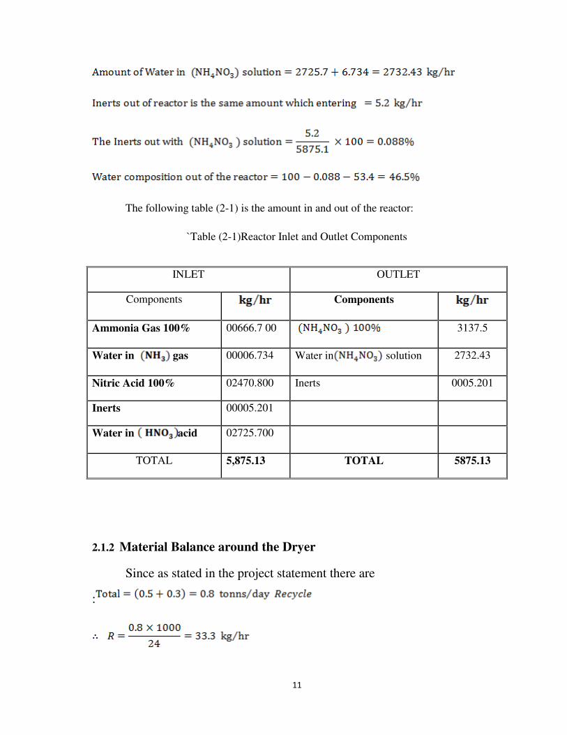
The following table (2-1) is the amount in and out of the reactor:
`Table (2-1)Reactor Inlet and Outlet Components
2.1.2 Material Balance around the Dryer
Since as stated in the project statement there are
:
INLET OUTLET
Components
Components
Ammonia Gas 100% 00666.7 00 3137.5
Water in gas 00006.734 Water in solution 2732.43
Nitric Acid 100% 02470.800 Inerts 0005.201
Inerts 00005.201
Water in acid 02725.700
TOTAL 5,875.13 TOTAL 5875.13

12
Since the moisture in each of is (o.1 moisture) (See Fig. (2-2)).
Water Vapour (H2O)
[ W6
W5
2% Moisture
W7
R1
W8
Fig. 2.2: Material balance around the dryer
Water Material Balance is:
2.1.3 Overall Material Balance
DRYER

13
Solving above equation:
The composition of Ammonia Nitrate Entering the dryer is (98%).
Table(2-2): Material Balance around the Dryer
INLET kg/hr OUTLET kg/hr
Ammonia Nitrate 100% 3167.629 Water Vapour 0061.470
Water Entering with
Ammonia Nitrate 0064.645 Ammonia Nitrate 100% 3167. 629
Moisture with Ammonia
Nitrate 0003.171
TOTAL 3232.27 TOTAL 3232.27

14
2.1.4 Material Balance Around the Washing Tower
W4 W5=3232.27 Kg/hr
2% Moisture
Fig. 2-3: Material balance around the Washing Tower
Overall material balance aroundthe washing tower:
2.1.5. Ammonium Nitrate Material Balance
The table(2-3) shows the Material Balance in and out of the Washing Tower: Table
2-3:Material Balance around Washing Tower
WASHING TOWER

15
INLET kg/hr OUTLET kg/hr
Ammonia Nitrate 100% 3179.87 Ammonia Nitrate 100% 3167.62
Water Entering with
Ammonia
Nitrate solution
0064.89 Water entering
withNH4NO3solution 0064.645
Amount of NH4NO3Washed
solution 0012.25
Amount of Water in washed
solution 0000.25
TOTAL 3244.76 TOTAL 3244.76
2.1.6 Material Balance around the Crystallizer
Since the outlet of the slurry is taken to washing tower and the rest
is solution is recycled to the evaporator, then:
The composition of the Recycled as shown in Fig.(2-4) can be calculated as
follows:

16
W3 W4=3244.77 Kg/hr
77% NH4NH3 2% Moisture
R1
Fig. 2-4: Material balance around the Crystallizer
So, Material Balance is:
Where is the composition of Recycled .
The table(2-4) shows the Material Balance around the Crystallizer
Table (2-4) Material Balance around Crystallizer
OUTLET kg/hr INLET kg/hr
CRYSTALEIZER

17
Ammonia Nitrate 100% 8328.219 Ammonia Nitrate 100% 3179.87
Water in NH4NO3solution 2487.65 Water inNH4NO3 solution 0064.89
Recycled NH4NO3 5148.35
Water in NH4NO3Recycled 2422.75
TOTAL 10815.86 TOTAL 10815.86
2.1.7 Material Balance Around the Evaporator Water vapour + (NO2)
W0=5879.765Kg/hr W1 W3=10815.87Kg/hr
R=33.3Kg/h R1=7571.109Kg/hr
98% NH4NO3 68% NH4NO3
Fig. 2-5: Material Balance around the Evaporator
2.1.6 Material Balance around the Branches
To find the solution Entering the evaporator, Material
Balance around the Branches:
EVAPORATOR
18
Assume the Inerts Entering with Nitric acid is and is removed in the Evaporator,
so the gases out of the Evaporator are
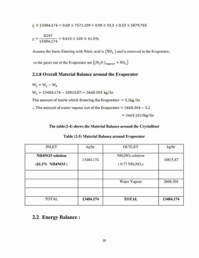
2.1.8 Overall Material Balance around the Evaporator
The table(2-4) shows the Material Balance around the Crystallizer
Table (2-5) Material Balance around Evaporator
INLET kg/hr OUTLET kg/hr
NH4NO3 solution
(61.5% NH4NO3 ) 13484.174
NH4NO3 solution
( 0.77 NH4NO3) 10815.87
Water Vapour 2668.304
TOTAL 13484.174 TOTAL 13484.174
2.2 Energy Balance :

19
2.2.1 Heat Balance around Ammonia Evaporator:
Fig. 2.7:EnergyBalance Around Ammonia Evaporator

20
2.2.2 Latent Heat for Steam at 11 bar
.
Where:
The amount of steam required to evaporate the NH3 :
So, the amount of steam required to increase the temperature of liquid ammonia from
(15°C) to saturation temperature of ammonia is:
2.2.3 Heat Balance around Nitric Acid Heater
Assume that Nitric acid entering the heater at ( ) and out at ( )

21
Fig. 2.8:Heat Balance around Nitric Acid Heater
Since the acid entering at ( ), then the Enthalpy:
Heat capacity of the acid at 47.5% (Ref. 3, Fig. 3.39):
2.2.4 Heat Balance around the Reactor

22
To calculate the heat of reaction at the temperature of the reaction:
Where:-
Data of heat of formation for the reactant and product is taken from (Ref. 3).
Temperature of entering ( to the reactor
Temperature of entering of Ammonia gas to the reactor

23
Where:
The amount of water required for cooling the reactor data:
=

24
2.2.5 Heat Balance around the Evaporator

25
To find out the amount of steam required to increase the composition of Ammonium
Nitrate solution from 61.5% to 77%, the heat balance around the Evaporator:
Heat balance around the Branch to find the temperature of inlet Ammonium Nitrate to the
Evaporator:

26
5875.13Kg/hr
(198.5
R=33.3 Kg/hr R1=7541.4 Kg/hr (23
From the Dryer From the Crystallizer
Fig2.2.3:Heat Balance around the Evaporator
2.2.6 Heat Balance around the Crystallizer to Find the Crystallization
Temperature

27
5148.2
100
TEMPERATURE SOLUBILITY
0 54 12 60 20 66 25 68 30 70 35 72 40 74 50 78 60 81 70 84 80 87 90 89 100 91 110 93 120 95 130 96 140 98 150 99

28
Fig. 2-4: The relation between Solubility versus Temperature for Ammonium Nitrate

29
Heat Balance around the Dryer

30
Solving to find out

31
CHAPTER 3
PROCESS DESIGN OF EVAPORATOR
3.1 Calculation Heat Transfer Surface Area
Where;
3.2 Calculation the Overall Heat Transfer in the Evaporator (Ref.3,
P.485)
Taking heat transfer coefficient of the steam flowing in the shell side:
Heat transfer coefficient of inside pipe of the evaporator (Forced circulation), can be
calculated from the equation:

32
To avoid scale formation on the inside of the pipe of this type of evaporator, solution
circulation flow rate should be high relative to the feed flow rate , for this reason we cannot
calculate the velocity based on feed flow rate. For design purpose, assume the velocity (2 to
5 m/s) inside the pipes.(Ref. 3, P. 485).
At this temperature, the physical properties of the solution inside the
evaporator:

33
To calculate the overall heat transfer coefficient, we use the following equation:
.

34
3.3 Use One Shell Pass and One Tube Pass
The steam flowing on shell side (clean fluid), so we use (1.25) triangular pitch.
3.3.1 Using a Split Ring Floating Head
Shell side:
35
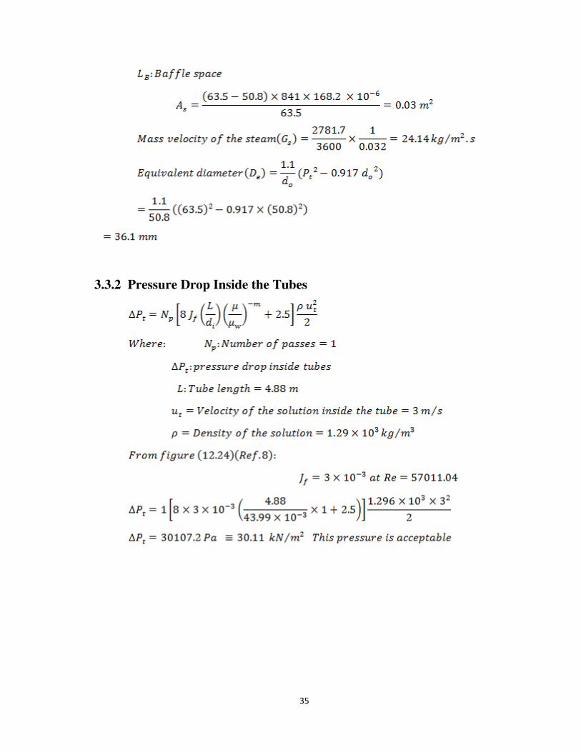
3.3.2 Pressure Drop Inside the Tubes

36
3.4 Process Design of the Vapor –Liquid Separator
3.5 Process Design of classifying vacuum crystallizer.

37
Table (3-1) Data of Temperature / Growth Rate Relation
Temperature Growth Rate
0 4.5
23 3.7
40 3.3

38
Fig. 3-1: Growth Rate of Ammonium Nitrate Crystals with Temperature

39
Where:

40
Where:
Where:

41
.

42
.(This is standard length) .
Note:
3.6 Choosing Pitch of Heat Exchanger

43

44
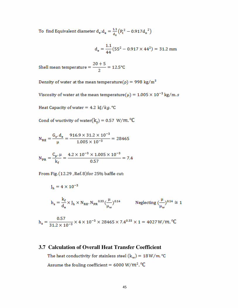
45
:
3.7 Calculation of Overall Heat Transfer Coefficient

46
3.8 .Calculation of Pressure Drop Inside Heat Exchanger
3.8.1 Pressure Drop Tube Side

47
3.8.2Pressure Drop Shell Side
3.9. Mechanical Design for Separator.
The following steps were used in mechanical design of the separator:
3.9.1Thickness of the Shell
Assume different value for the thickness. The following ratio was estimated:
To estimate the pressure, which the thickness assumed can be taken:
: is a constant that can be found from the graph ), according to
the material of construction with the ratio which were tested at temperature of

48
in the evaporator. The value of pressure allowed is close to atmospheric
pressure, then the assumed value of the thickness.
In the graph to find the thickness of the shell required from the different
thicknesses where we find shell thickness is the lowest value for allowed
pressure (Atmospheric pressure) to assure this value the following steps were
followed:
So;
From , choose the next higher available plate thickness for actual fabrication:
Choosing for actual thickness.

49
3.9.2Design for the Atmospherically dished closure (cover)
Assuming different values for the thickness of dish and was found thickness of
is the minimum which can take the allowable pressure (atmospheric Pressure).
Following the procedure used in (
3.9.3 Design of conical closure
Choosing different values for the thickness and was found that thickness of is
the proper one for pressure of one atmosphere we follow the procedure in

50
3.10. Calculation the Nozzle Size on Wall of the Separator
To calculate the diameter of the nozzle, the following procedure is to be followed:
Consider that diameter of nozzle is equal to the outlet diameter nozzle flow of vapour.
So, the inlet nozzle to separator :

51
Note:
The actual velocity through feed nozzle to the separator is lower than above value. This is
due that it is calculated for complete evaporation in the heat exchanger before entering
the separator, but actually most evaporation is happen in flash chamber.
3.11.The Velocity through Outlet of the Separator
Consider that diameter of the nozzle is equal to half diameter of inlet diameter to the
separator. i.e.
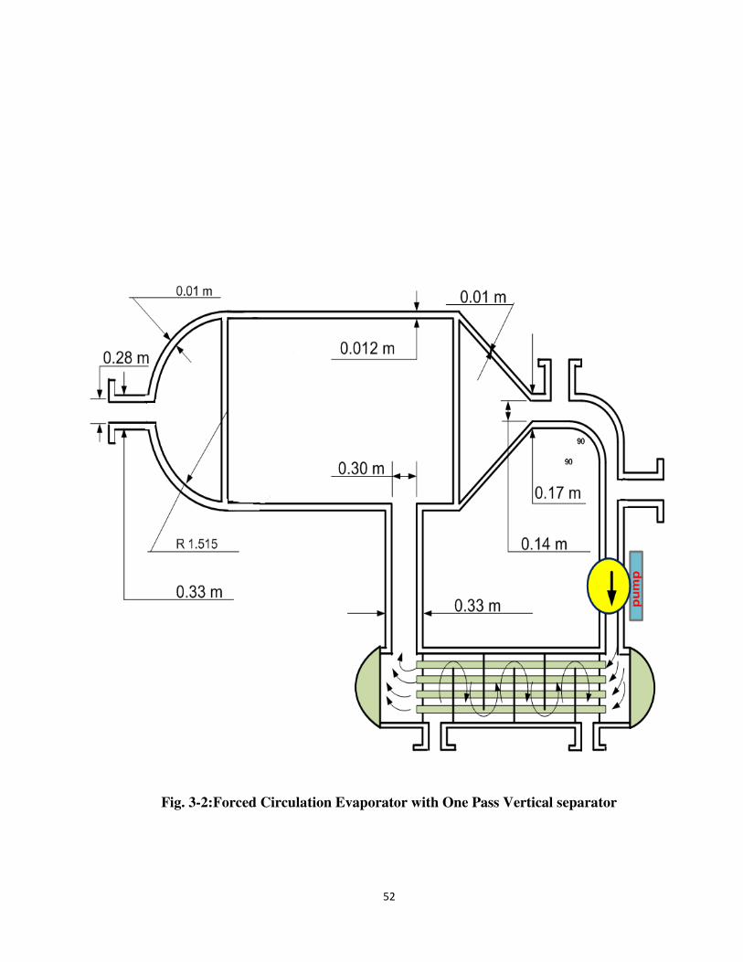
52
Fig. 3-2:Forced Circulation Evaporator with One Pass Vertical separator

53
CHAPTER 4
INSTRUMENTATION AND CONTROL
4.1.Instruments
Instruments are provided to monitor the key process variables during plant operation. They
may be incorporated in automatic control loops, or used for the manual monitoring of the
process operation. Instruments monitoring critical process variables will be fitted with
automatic alarms to alert the operators to critical and hazardous situations.
It is desirable that the process variable to be monitored be measured directly; often,
however, this is impractical and some dependent variable, that is easier to measure, is
monitored in its place. For example, in the control of distillation columns the continuous,
on-line, analysis of the overhead product is desirable but difficult and expensive to achieve
reliably, so temperature is often monitored as an indication of composition. The
temperature instrument may form part of a control loop controlling, say, reflex flow; with
the composition of the overheads checked frequently by sampling and laboratory analysis.
4.1.1Instrumentation and control objectives
The primary objectives of the designer when specifying instrumentation and control
schemes are:
I. Safe plant operation
a) To keep the process variables within known safe operating limits.
b) To detect dangerous situations as they develop and to provide alarms and
automatic shut-down systems.
c) To provide interlocks and alarms to prevent dangerous operating procedures.
II. Production rate:
To achieve the design product output.
III. Product quality:

54
To maintain the product composition within the specified quality standards.
IV. Cost:
To operate at the lowest production cost, commensurate with the other objectives. These
are not separate objectives and must be considered together. The order in which they are
listed is not meant to imply the precedence of any objective over another, other than that of
putting safety first. Product quality, production rate and the cost of production will be
dependent on sales requirements. For example, it may be a better strategy to produce a
better-quality product at a higher cost.
In a typical chemical processing plant, these objectives are achieved by a combination of
automatic control, manual monitoring and laboratory analysis
4.1.2Guide Rules:
The following procedure can be applied when drawing up preliminary (P &I) diagrams:
I. Identify and draw in those control loops that are obviously needed for steady plant
operation, such as:
a) Level controls,
b) Flow controls,
C) Pressure controls
d) Temperature controls.
II. Identify the key process variables that need to be controlled to achieve the specified
product quality.
III. Identify and include those additional control loops required for safe operation.
IV. Decide and show those ancillary instruments needed for the monitoring of the plant
operation by the operators.
V. Decide on the location of sample points.
VI. Decide on the need for recorders and the location of the readout points.
4.2.Typical control systems

55
4.2.1Level Control
In any equipment where an interface exists between two phases (e.g. liquid-vapour),
some means of maintaining the interface at the required level must be provided. This may
be incorporated in the design of the equipment, as is usually done for decanters or by
automatic control of the flow from the equipment.
Figure (5-1) shows a typical arrangement for the level control at the base of a
column. The control valve should be placed on the discharge line from the pump.
Fig. 4-1:A typical arrangement for the level control
4.2.2Pressure Control
Pressure control will be necessary for most systems handling vapor or gas. The method of
control will depend on the nature of the process. Typical schemes are shown in Figure (8-2)
The scheme would not be used where the vented gas was toxic, or valuable. In these
circumstances the vent should be taken to a vent recovery system, such as a scrubber.
Fig. 4-2:Atypical arrangement for the pressure control
4.2.3Ratio Control

56
Ratio control can be used where it is desired to maintain two flows at a constant ratio; for
example, reactor feeds and distillation column reflux. A typical scheme for ratio control is
shown in the following figure.
Fig. 4-3:A typical scheme for ratio control
4.2.4Flow Control
Flow control is usually associated with inventory control in a storage tank or other
equipment. There must be a reservoir to take up the changes in flow-rate .To provide flow
control on a compressor or pump running at a fixed speed and supplying a near constant
volume output, a by-pass control would be used, as shown in figure(8-3).
Fig. 4-4:Atypical arrangement for the flow control
4.2.5Temperature Control
57
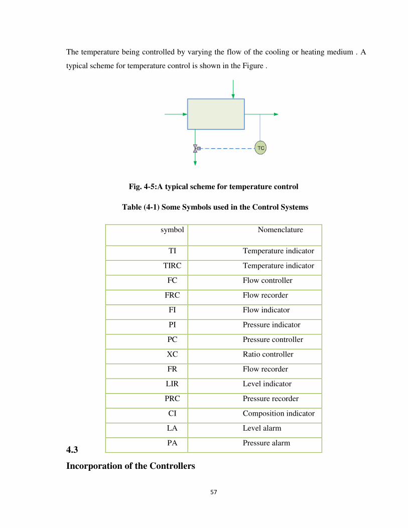
The temperature being controlled by varying the flow of the cooling or heating medium . A
typical scheme for temperature control is shown in the Figure .
Fig. 4-5:A typical scheme for temperature control
Table (4-1) Some Symbols used in the Control Systems
4.3
Incorporation of the Controllers
symbol Nomenclature
TI Temperature indicator
TIRC Temperature indicator
FC Flow controller
FRC Flow recorder
Controller FI Flow indicator
PI Pressure indicator
PC Pressure controller
XC Ratio controller
FR Flow recorder
LIR Level indicator
recorder PRC Pressure recorder
controller CI Composition indicator
LA Level alarm
PA Pressure alarm

58
The following scheme in Figure (4-6) shows incorporation of controllers in the automatic
control system of the plant.

59
Fig. 4-6: FLOW SCHEME OF TYPICAL PROCESS WITH CONTROLLERS
CHAPTER 5
SAFFTY AND ENVIRONMENTAL
5.1 Introduction
The following general safety rules shall be observed when working with chemicals;
Read and understand the Material Safety Data sheets (MSDS).
Keep the work area clean and orderly.
Use the necessary safety equipment.
Carefully label every container with the identity of its contents and appropriate hazard
warnings.
Store in compatible chemicals in separate areas.
Substitute less toxic materials whenever possible.
Limit the volume of volatile or flammable material to the minimum needed for short
operation periods.
Provide means of containing the Material if equipment or containers should break or spill
their contents.
5.2 Task Evaluation
Each task that requires the use of chemicals be evaluated to determine the potential hazards
associated with the work. This hazard evaluation must include the chemical or combination
of chemicals that will be used in the work, as well as other materials that will be used near
the work
5.3 Chemical Storage
The separation of chemicals (solids or liquids) during storage is necessary to reduce the
possibility of unwanted chemical reactions caused by accidental mixing. Explosives should
60
be stored separately outdoors. Use either distance or barriers (e.g., trays) to isolate
chemicals into the following groups :
Flammable Liquids: store in approved flammable storage lockers.
Acids: treat as flammable liquids.
Bases: do not store bases with acids or any other material.
Other liquids: ensure other liquids are not incompatible with any other
chemical in the same storage location.
Lips, strips, or bars are to be installed across the width of storage shelves to
restrain the chemicals in case of earthquake.
Chemicals will not be stored in the same refrigerator used for food storage.
Refrigerators used for storing chemicals must be appropriately identified by
a label on the door.
5.4.Emergencies and Spills
In case of an emergency, implement the following proper Emergency Action Plan;
1. Evacuate people from the area.
2. Isolate the area.
3. If the material is flammable, turn off ignition and heat sources.
4. Only personnel specifically trained in emergency response are permitted to
participate in chemical emergency procedures beyond those required to evacuate
the area.
5. Call for Emergency Response Team assistance if required.
5.5.Housekeeping

61
Maintain the smallest possible inventory of chemical to meet immediate
needs.
Periodically review stock of chemicals on hand.
Ensure that storage areas, or equipment containing large quantities of
chemicals, are secure from accidental spills.
Rinse emptied bottles that contain acids or inflammable solvents before
disposal.
Recycle unused laboratory chemicals wherever possible.
Do not place hazardous chemicals in salvage or garbage receptacles.
Do not pour chemicals onto the ground.
Do not dispose of chemicals through the storm drain system.
Do not dispose of highly toxic, malodorous chemicals down sinks or sewer
drains.
5.6.MSDS Information
Material Safety Data Sheets are provided by the chemical manufacturer to provide
additional information concerning safe use of the product. Each MSDS provides:
1.Common Name and Chemical Name of the material.
2. Name, address and phone number of the manufacturer.
3. Emergency phone numbers for immediate hazard information.
4. Data the MSDS was last updated.
5. Listing of hazardous ingredients.
6. Chemical hazards of the material.
7. Information for identification of chemical and physical properties.

62
5.7.Chemical Users Information
Chemical Users must have a good knowledge about “Fire and/or Explosion Information”
(i.e):-
1. Material Flash Point, auto-ignition temperature and upper/lower flammability
limits.
2. Proper fire extinguishing agents to be used.
3. Fire fighting techniques.
4. Any unusual fire or explosive hazards.
5.8.Chemical Reaction Information
1. Stability of Chemical.
2. Conditions and other materials which can cause reactions with the chemical.
3. Dangerous substance that can be produced when the chemical reacts.
5.9.Control Measures
1. Engineering Controls required for safe product use.
2. Personal protective equipment required for use of product.
3. Safe storage requirements and guidelines.
4. Safe handling procedures.
5.10.Health Hazards
Health and safety data are shown on the material safety data sheets which are available
from suppliers and can be found on the internet.

63
Ammonium Nitrate is not very hazardous to health and is usually used in fertilizer
products.
The chances of direct personal exposure to the chemical are very low, because the
fertilization of the soil by use of Ammonium Nitrate is done at early stages of plant growth
and usually does not remain detectable on the harvested plants or when the plants reach the
consumer.
Ammonium Nitrate has an LD50 of 2217mg/kg,. which for comparison is about two-thirds
that of table salt.
5.11 Safety and Environment Precautions
The main concern is mainly with precautions and protocols that are to be followed
while handling materials in the plant. Safety equipment includes: “splash goggles,
protective coats, gloves and safety shoes” are all required in dealing with these materials
regardless of their reactivity and stability. These documentations will include the two target
materials and compounds encountered and utilized in the plant as follows:
5.11.1Acute Health Effects
Short-term exposure to Ammonium Nitrate can cause symptoms ranging from minor
irritation to nausea, vomiting, gastric irritation, headaches, dizziness, and hypertension.
Table (5-1) Exposure and Hazard Level
Area of expo Area of exposure sure Hazard level Hazard level
Ingestion Moderately hazardous
Skin contact Moderately hazardous (irritant)
Eye contact Moderately hazardous
Inhalation Moderately hazardous

64
5.11.2 Long-Term Health Effects
The toxicity of Nitrates when ingested is due to in vivo conversion to Nitrites. The
material safety data sheet considers chronic ingestion of more than 5mg/kg/day
unacceptable. The primary overdose effects of chronic exposure are orthostatic
hypotension and methemoglobinemia. Other common effects include: faintness, fatigue,
weakness, depression, mental impairment, dizziness, shortness of breath, and reflex
tachycardia; headache, nausea, vomiting, and nephritis may also occur.
Table (5-2) Type of Effect and Effect Level
Types of effect Effect level
Carcinogenic effects
Though no Ammonium Nitrate-specific studies are available, nitrates
can be reduced to nitrites in the body, and the formed nitrites can
subsequently react with amines to form suspect carcinogens N-
nitrosamine.
Mutagenic effects In general, nitrates and nitrites are genotoxic.
Teratogenic effects None
Developmental
toxicity
Though not specific to Ammonium Nitrate, some studies have shown
a link between birth defects (particularly neural tube defects) and
nitrate-contaminated well water.
Prolonged exposure
Causes damage to lungs and mucous membranes and may also cause
damage to blood and gastrointestinal tract. Chronic ingestion may also
cause nephritis.[19]

65
CHAPTER 6
MATERIAL OF COST
6.1 Introduction to Material of Construction
Ammonium Nitrate solution is one of solutions which causes corrosion to the most
of metals especially copper and its alloys.
Stainless steel resisting corrosion of the type 304 and 316 are used to handle hot
Ammonium Nitrate solutions. Pumps and valves constructed from FA-20 alloy which
contains 20%Cr, 29%Ni and small amount of molybdenum, copper and silicon.
Stainless steel resisting corrosion has a wide use in chemical process plants.
The resisting properties of the stainless steel can be improved by increasing the
amount of Cr, which can give better corrosion resistance at oxidation environment.
Increasing Ni content improves corrosion resistance in non-oxidation environment.
Stainless steel 304 and some time called (18/8) stainless steel , is the usual type of
stainless steel resistance to corrosion and which contains the minimum amount of Cr and
Ni which give Austinic composition and contains less amount of carbon to give a good heat
treatment to prevent removal of welding.
Stainless steel 316 corrosion resistance, molybdenum is to improve the properties
for corrosion resisting in the reduction environment.
The following tables are the constructional information and sizing for each
equipment
6.2The Sizing of the Plant
The following tables are the sizing for each equipment in the plant:

66
Table (6-1) Sizing of Ammonia Vaporizer
CLASSIFICATION VAPORIZER
Number Required 1
Job/Duty Evaporation of Liquid NH3
Type Heat Exchanger Steam Heated
Operation Continuous
Flow Rate Capacity 673.4 kg/hr
Material Handled Ammonia
Outlet Temperature
Shell Type Horizontal Cylindrical Shell
Ammonia Composition
Material of Construction Carbon Steel
Table (6-2) Sizing of Nitric Acid Heat Exchanger
CLASSIFICATION HEAT EXCHANGER
Number Required 1
Job/Duty Increasing Temperature of HNO3
Operation Continuous
Temperature
Nitric Acid Composition
Material of Construction Carbon Steel
Flow Rate Capacity

67
Table (6-3) Sizing of Reactor
CLASSIFICATION REACTOR
Number Required 1
Job/Duty Reaction of Ammonia with Nitric Acid to Produce
NH NO Type Fluidized Bed Reactor
Operation Continuous
Material of Construction Stainless Steel 316
Type of Reaction Exothermic Reaction
Flow Rate Capacity
Material Handled Ammonium Nitrate
Temperature
Table (6-4) Sizing of Evaporator
CLASSIFICATION EVAPORATOR
Number Required 1
Job/Duty Concentration of NH4NO3Solution
Type Single Vacuum Evaporator with Forced Circulation
Temperature
Flow Rate Capacity
Material Handled Ammonium Nitrate
Diameter
Material of Construction Stainless Steel 304L
Length

68
Table (6-5) Sizing of Crystallizer
CLASSIFICATION CRYSTALLIZER
Number Required 1
Job/Duty To Get the Required Crystals
Type Classifying Vacuum Crystallizer
Temperature
Flow Rate Capacity
Material Handled Ammonium Nitrate Solution
Material of Construction Stainless Steel 304
Diameter
Length
Density of NH4NO3 Crystals
Table (6-6) Sizing of Ammonium Nitrate Dryer
CLASSIFICATION DRYER
Number Required 2
Job/Duty Moisture Removal
Type Rotary Counter Current Dryer
Material Handled Ammonium Nitrate
Flow Rate Capacity
Inlet Air Temperature
Material of Construction Carbon Steel

69
EQUIPMENT COST ESTIMATING:
Reactor
Number: 1
Description:
Type: Mixer/settler
Material: Carbon steel
Pressure (psi): 300 psi (20.4 atm)
Costs
Year 2018 Cost : (€) € 249,981.00
Year 2018 Cost : ($) $217,484.00
Heat exchanger
Number: 1
Description:
Type: Shell/tube, fixed/U, large
Material: Carbon steel
Pressure (psi): 300 psi rating (20.4 atm)
Costs
Year 2018 Cost : (€) € 102,673.00

70
Year 2018 Cost : ($) $89,326.00
Heat exchanger
Number: 2
Description:
Type: Shell/tube, fixed/U, large
Material: Carbon steel
Pressure (psi): 300 psi rating (20.4 atm)
Costs
Year 2018 Cost : (€) € 102,673.00
Year 2018 Cost : ($) $89,326.00
Ejector
Number: 1
Description:
Type: Ejector, large
Material: Carbon steel
Pressure (psi): 125 psi rating (8.5 atm)
Costs
Year 2018 Cost : (€) € 4,181.00
Year 2018 Cost : ($) $3,637.00
Crystallizer
Number: 1
Description:

71
Type: Batch vacuum
Material: Carbon Steel
Volume (l): 14006
Costs
Year 2018 Cost : (€) € 140,176.00
Year 2018 Cost : ($) $121,953.00
Compressor
Number: 1
Description:
Type: Centrifugal, 1000 psi (68.0 atm)
Material: Carbon steel
Compressor
Power(kW): 1334
Costs
Year 2018 Cost : (€) € 679,487.00
Year 2018 Cost : ($) $591,153.00
Boiler
Number: 1
Description:
Type:
Oil/gas Fired field fab 150 psi sat (10.2
atm)
Material: Carbon steel
Boiler capacity
(kg/hr): 249475
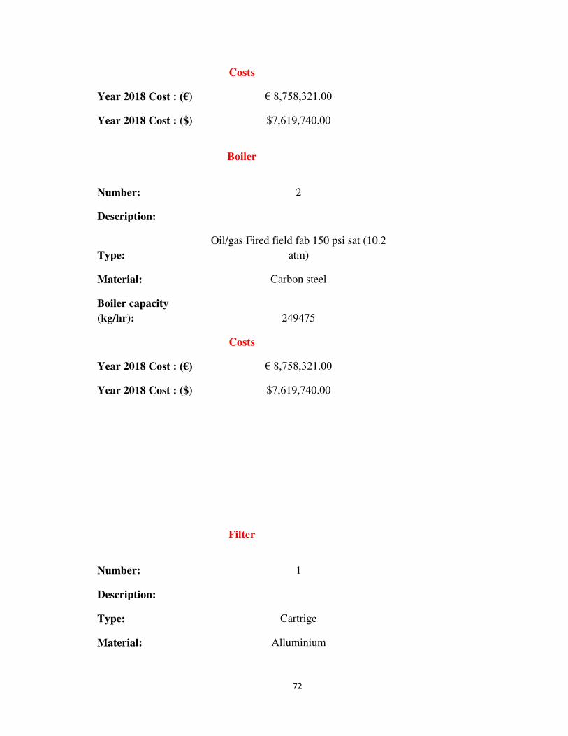
72
Costs
Year 2018 Cost : (€) € 8,758,321.00
Year 2018 Cost : ($) $7,619,740.00
Boiler
Number: 2
Description:
Type:
Oil/gas Fired field fab 150 psi sat (10.2
atm)
Material: Carbon steel
Boiler capacity
(kg/hr): 249475
Costs
Year 2018 Cost : (€) € 8,758,321.00
Year 2018 Cost : ($) $7,619,740.00
Filter
Number: 1
Description:
Type: Cartrige
Material: Alluminium

73
Filter area (m2): 56.205
Costs
Year 2018Cost : (€) € 73,900.00
Year 2018 Cost : ($) $64,293.00
Filter
Number: 2
Description:
Type: Cartrige
Material: Alluminium
Filter area (m2): 56.205
Costs
Year 2018 Cost : (€) € 73,900.00
Year 2018 Cost : ($) $64,293.00
Cooling and Refrigeration
Number: 1
Description:
Type: Cooling pond
Material: Carbon steel
Cooling load
(kW/hr): 4930
Costs
Year 2018 Cost : (€) € 56,808.00

74
Year 2018 Cost : ($) $49,423.00
Cooling and Refrigeration
Number: 2
Description:
Type: Cooling pond
Material: Carbon steel
Cooling load
(kW/hr): 4930
Costs
Year 2018 Cost : (€) € 56,808.00
Year 2018 Cost : ($) $49,423.00
Centrifugal pump
Number: 1
Description:
Type: Horizontal 1 stage hor. Split
Material: Cast iron;API 610
Seal type: Packing
Costs
Year 2018Cost : (€) € 5,779.00
Year 2018Cost : ($) $5,028.00

75
Centrifugal pump
Number: 2
Description:
Type: Horizontal 1 stage hor. Split
Material: Cast iron;API 610
Seal type: Packing
Costs
Year 2018 Cost : (€) € 5,779.00
Year 2018 Cost : ($) $5,028.00
Centrifugal pump
Number: 1
Description:
Type: Horizontal API-610-1 stage
Material: Cast iron;API 610
Seal type: Packing
Costs
Year 2018 Cost : (€) € 14,632.00
Year 2018 Cost : ($) $12,730.00
Centrifugal pump

76
Number: 2
Description:
Type: Horizontal API-610-1 stage
Material: Cast iron;API 610
Seal type: Packing
Costs
Year 2018 Cost : (€) € 14,632.00
Year 2018 Cost : ($) $12,730.00
Centrifugal pump
Number: 1
Description:
Type: Vertical Sump 1stage
Material: Cast iron;API 610
Seal type: Packing
Costs

77
Year 2018 Cost : (€) € 8,484.00
Year 2018 Cost : ($) $7,381.00
Centrifugal pump
Number: 1
Description:
Type: Vertical turbine 4 stage
Material: Cast iron;API 610
Seal type: Packing
Costs
Year 2018 Cost : (€) € 6,025.00
Year 2018 Cost : ($) $5,242.00
Vacuum pump
Number: 1
Description:
Type: Blower, 1-stage dry seal, medium
Material: Alloy 20
Flowrate(l/min): 14032
Costs
Year 2018 Cost : (€) € 29,142.00
Year 2018 Cost : ($) $25,353.00

78
Vacuum pump
Number: 1
Description:
Type: Blower, 1-stage liquid seal, large
Material: Alloy 20
Flowrate(l/min): 54032
Costs
Year 2018 Cost : (€) € 36,889.00
Year 2018 Cost : ($) $32,093.00
Separator
Number: 1
Description:
Type: Cyclone, wet, NiHard lined, medium
Material: Carbon steel
Diameter (m): 0.3
Costs
Year 2018 Cost : (€) € 3,935.00

79
Year 2018 Cost : ($) $3,423.00
Separator
Number: 1
Description:
Type: Screw classifier, 2-screw
Material: Carbon steel
Diameter (m): 0.98
Costs
Year 2018 Cost : (€) € 61,604.00
Year 2018 Cost : ($) $53,595.00
Tank
Number: 1
Description:
Type: Vertical, cone top &bottom,small
Material: Aluminium

80
Volume (l): 19457
Costs
Year 2018 Cost : (€) € 35,044.00
Year 2018 Cost : ($) $30,488.00
Tank
Number: 2
Description:
Type: Vertical, cone top &bottom,small
Material: Aluminium
Volume (l): 19457
Costs
Year 2018 Cost : (€) € 35,044.00
Year 2018 Cost : ($) $30,488.00
Heat exchanger
Number: 1
Description:
Type: Air cooled, bare tube area
Material: Carbon steel
Pressure (psi): 150 psi rating (10.2 atm)
Costs
Year 2018 Cost : (€) € 214,322.00
Year 2018 Cost : ($) $186,460.00

81
Heat exchanger
Number: 1
Description:
Type: Evaporator, vertical tube
Material: Carbon steel
Pressure (psi): 150 psi rating (10.2 atm)
Costs
Year 2018 Cost : (€) € 750,805.00
Year 2018 Cost : ($) $653,200.00
Total Equipment
Cost = $17,635,649.00

82
CHAPTER 7
PLANT LAYOUT AND CONCLUSION

83
84

85
CONCLUSSION
A plant is to be designed for production of (22590 tons /year) of crystalline
Ammonium Nitrate coming with the reactions of nitric acid and liquid ammonia.
Feed component concentration;
i. Nitrate acid is 47.5 %W containing 52.5 %w water.
ii. Liquid ammonia under pressure, (99%W NH3) containing (1%) water, is
available and storage is also required at least for this for (48 hours) supply.
iii. The crystals are withdrawn as (30%) slurry.
The dried product contains (0.1%) moisture is sieved and the undersize product is recycled
together with the dust from the drier to the evaporator stage.
REFERENCES
System Temperature (°C) State Volume change (%)
> 169.6 Liquid
I 169.6 to 125.2 Cubic +2.1
II 125.2 to 84.2 Tetragonal −1.3
III 84.2 to 32.3 α-rhombic +3.6
IV 32.3 to −16.8 β-rhombic −2.9
V −16.8 Tetragonal

86
1. “ Encyclopedia of chemical Technology”, Vol. 2 ,
by: Kirk-Othmer , Third Edition.
2. “ Unit Operation of Chemical Engineering”
by: Jolian C. Smith and Warren L. McCabe, 1984.
3. “Transport Process and Unit Operation”
by: Christie J. Geankoplies, (Allyn and Bacon, INC, 1983).
4. “ Basic Principles and Calculation in Chemical Engineering”
by: David M. Himmelbau (Printice-Hall, INC, 1982).
5. “Shreve’s Chemical Process Industries”
by: George T. Austin (McGraw Hill, 1984).
6. “Chemical Engineering Handbook”
by: R.H. Perry and C.H. Chilton 5th edition,(McGraw Hill, 1973).
7. “Applied Process Design for Chemical and Petrochemical Plants”, Vol. 3 by: Ernest E.
Ludwig, 1983.
8. “Chemical Engineering” Vol. 6
by: J. M. Coulson, J. F. Richardson, 1982.
9. “Petroleum Refinery Engineering”
by: W. L. Nelson, 1969.
10. “Encyclopedia of Chemical Processing and Design “ Vol. 13 ,
by: John J. Mcketta, 1981..
11. “Process Control”
by: A. pollard, 1971.
12. “Process Design for Reliable Operation”
by: Norman P. Leberman.

87

88
APPENDICES
Appendix A
*
*
*
*

89
Appendix B
*
*
*
*
Appendix C
*
*
*
*
Appendix D
*
*
*
*
ضوابط كتابة الرسالة العلمية
.تكتب الرسالة باللغة الانجليزية فقط بما في ذلك صفحة "التهنئة" لغة الرسالة : ∙1
عبارة عن ملخص باللغة الانجليزية لمادة الرسالة )على سبيل المثال الملخص : ∙2والغرض من إجرائها وأهم النتائج التي تم الوصول اليها دون الدخول في التجارب العملية(
تفاصيل التجربة او الاستنتاجات الرياضية. ويتحتم على معد التقرير الاهتمام قدر الامكان بكتابة المخلص لأنه في كثير من الحالات يحدد الملخص رغبة القارئ في مطالعة بقية
كلمة. 200تجاوز عدد كلماته التقرير من عدمها على أن لا ي
تطبع الرسالة على ورق ابيض مقاس : الورق : ∙3
A4 (210×297mm)
.وتكون الطباعة على وجه واحد من الورق وباللون الاسود
نوع الخط : ∙4

90
اولاً العناوين الرئيسية .. Times New Roman, 16-Bold, UPPERCASE
ثانياً العناوين الفرعية الاولى ..Times New Roman, 14-Bold, Capitalize Each Word
ثالثاً العناوين الفرعية الثانية والثالثة .. الخTimes New Roman, 14-Bold, Sentence case
رابعاً مادة الرسالة ..
Times New Roman, 12, Sentence case
الهوامش : ∙5
سم من باقي الجوانب. 2.5سم من الجانب الايسر و 3.5يترك هامش عرضه
الفراغ بين السطور : ∙6
1.5 Space
الترقيم : ∙7
يتم ترقيم الصفحات الاعدادية )الملخص و جدول المحتويات ...الخ( في وسط اسفل الصفحة بالأحرف اللاتينية :
i,ii,iii,iv,v,vi ية في وسط اسفل الصفحة بالارقام :ويتم ترقيم الصفحات الاساس
1,2,3,4,…... عدد النسخ المطلوب : ∙8
.ثلاث نسخ ورقية وقرص مدمج
عدد الصفحات : ∙9
.صفحة 100وان لايتجاوز 60يجب ان لايقل عدد صفحات التقرير عن
نسبة النسخ المسموحة : ∙10
. % كحد اقصى30يجب ان لا تتجاوز نسبة النسخ في كامل الرسالة
تنسيق المكونات : ∙11
يتم اتباع التعليمات المتوفرة في النموذج المرفق أعلاه.