libretto di istruzione- - gastgastmfg.com/uploads/manuals/8702036-r7_en_gast.pdf · vacuum...
TRANSCRIPT

VACUUM
TECHNOLOGY
OPERATING AND MAINT ENANCE
INSTRUCTIONS
VACUUM PUMPS WITH RECIRCULATING LUBRICATION SYSTEM
LC.2 LC.4 LB.5 LB.6 LB.8 LC.12 LC.20

Operating and Maintenance Instructions
EN LC.2 – LC.4 – LB.5 – LB.6 – LB.8 – LC.12 – LC.20
2
8702036 – 12/27/2016 – R.7 www.gastmfg.com
INDEX
1 INTRODUCTION .................................................................................................................................................... 3
1.1 GENERAL INFORMATION .............................................................................................................................. 3 1.2 METHOD OF CONSULTATION ...................................................................................................................... 3 1.3 PERSONNEL QUALIFICATIONS .................................................................................................................... 3 1.4 PERSONAL PROTECTION EQUIPMENT ...................................................................................................... 3 1.5 INFORMATION PLATE ................................................................................................................................... 3
2 SAFETY ................................................................................................................................................................. 4
2.1 GENERAL WARNINGS ................................................................................................................................... 4 2.2 RESIDUAL RISKS ........................................................................................................................................... 4 2.3 PICTOGRAMS ................................................................................................................................................. 4
3 PUMP DESCRIPTION ........................................................................................................................................... 6
3.1 INTENTED USE AND RESTRICTIONS .......................................................................................................... 6 3.1.1 INTENTED USE ........................................................................................................................................ 6 3.1.2 RESTRICTIONS........................................................................................................................................ 6
3.2 FKM VERSION ................................................................................................................................................ 6 3.3 DIMENSIONS AND CHARACTERISTICS ....................................................................................................... 7
3.3.1 Model: LC.2 – LC.4 .................................................................................................................................. 7 3.3.2 Model: LB.5 .............................................................................................................................................. 8 3.3.3 Model: LB.6 – LB.8 ................................................................................................................................... 9 3.3.4 Model: LC.12 .......................................................................................................................................... 10 3.3.5 Model: LC.20 .......................................................................................................................................... 11
3.4 NOISE EMISSION ......................................................................................................................................... 12
4 INSTALLATION ................................................................................................................................................... 12
4.1 RECEIPT AND CONTENT VERIFICATION .................................................................................................. 12 4.2 PACKAGING .................................................................................................................................................. 12 4.3 TRANSPORT AND HANDLING ..................................................................................................................... 12 4.4 STORAGE ..................................................................................................................................................... 12 4.5 ENVIRONMENTAL CONDITIONS ................................................................................................................ 13 4.6 PUMP INSTALLATION .................................................................................................................................. 13 4.7 USER SYSTEM ............................................................................................................................................. 13 4.8 CONNECTION ............................................................................................................................................... 13
4.8.1 INTAKE AND OUTLET CONNECTIONS ................................................................................................ 13 4.8.2 WIRING ................................................................................................................................................... 14
5 OPERATING INSTRUCTIONS ............................................................................................................................ 15
5.1 OPERATION .................................................................................................................................................. 15 5.1.1 FILLING THE OIL TANK ......................................................................................................................... 15 5.1.2 START-UP .............................................................................................................................................. 15 5.1.3 STOP ....................................................................................................................................................... 15 5.1.4 PUMPING WATER VAPOUR ................................................................................................................. 15
6 MAINTENANCE ................................................................................................................................................... 16
6.1 GENERAL WARNINGS ................................................................................................................................. 16 6.2 MAINTENANCE TABLE ................................................................................................................................ 16
6.2.1 CHECK OIL LEVEL ................................................................................................................................. 16 6.2.2 CHANGE OIL .......................................................................................................................................... 16 6.2.3 CLEAN MOTOR FAN GUARD EAND CLEAN THE PUMP .................................................................... 17 6.2.4 CHANGE THE AIR EXHAUST FILTER .................................................................................................. 17 6.2.5 CHANGE VANES .................................................................................................................................... 17
6.3 SPARE PARTS .............................................................................................................................................. 17
7 HOW TO RETURN THE PUMP ........................................................................................................................... 18
8 DISMANTLING .................................................................................................................................................... 18
9 TROUBLESHOOTING ......................................................................................................................................... 19
10 WARRANTY................................................................................................................................................. 20

Operating and Maintenance Instructions
EN LC.2 – LC.4 – LB.5 – LB.6 – LB.8 – LC.12 – LC.20
3
8702036 – 12/27/2016 – R.7 www.gastmfg.com
1 INTRODUCTION
1.1 GENERAL INFORMATION This manual is meant to provide you with important information for the safety of persons involved in pump use and maintenance. This manual is an integral part of the pump and must be preserved with care for the life of the pump itself. In the event of sale, lease or loaned use of the pump, it must be delivered to the new user along with EC declaration of conformity. Carrying out any operations on the pump before reading and fully understanding all instructions in this manual is prohibited. The images contained in this document are examples only and are not binding for the Manufacturer. The Manufacturer reserves the right to make changes to components, product improvement parts and any other without updating this manual, if said components or parts do not alter pump operation and safety.
1.2 METHOD OF CONSULTATION For improved understanding of the information provided in this manual, warnings or instructions considered critical or hazardous are marked with the following symbols:
HAZARD
Failure to comply with these instructions may cause hazards to persons.
WARNING
Failure to comply with these instructions may cause damage to the pump.
1.3 PERSONNEL QUALIFICATIONS To ensure that all operations performed on the pump are carried out safely, operators must have the qualifications and requirements to carry out its operations. Operators are classified as follows:
FIRST LEVEL OPERATOR: Unqualified personnel, having no specific skills, able to perform simple tasks only.
MECHANICAL MAINTENANCE OPERATOR: Technician qualified to work on mechanical parts to carry out any necessary adjustments, maintenance or repairs. Not qualified to work on electrical systems in the presence of voltage.
ELECTRICAL MAINTENANCE OPERATOR: Technician in charge of all operations of an electrical nature. Can operate in the presence of voltage inside cabinets and connector boxes.
1.4 PERSONAL PROTECTION EQUIPMENT This manual assumes that the pump has been installed in workplaces, which comply with all mandatory safety requirements; in particular, it is mandatory that personnel are equipped with personal protective equipment in relation to the activities that must be performed.
1.5 INFORMATION PLATE All pumps are equipped with an identification plate that contains CE marking and technical data of the pump itself.
WARNING
Removing or tampering with the identification plate is strictly prohibited.

Operating and Maintenance Instructions
EN LC.2 – LC.4 – LB.5 – LB.6 – LB.8 – LC.12 – LC.20
4
8702036 – 12/27/2016 – R.7 www.gastmfg.com
2 SAFETY
2.1 GENERAL WARNINGS It is important to read this manual before performing any operation on the pump. Compliance with the safety standards of the country in which the pump is installed and requirements of qualified personnel for various maintenance, use, installation, etc. are recommended throughout the life of the pump. The main rules of conduct to be observed for operation at a suitable level of security are the following:
Installation, operation, maintenance, etc. operations should always be performed by qualified, trained personnel.
Without exception, always wear necessary personal protective equipment.
Always perform all cleaning, adjustment and maintenance operations with power supply disconnected.
Do not direct water jets toward electrical parts, even if they are protected by enclosures.
Do not smoke during work or maintenance, especially where solvents or flammable materials are being used.
Do not damage symbol plaques or pictograms on the pump. If they should accidentally become damaged, immediately replace them with other identification plaques.
Gast disclaims any liability for damage to persons or property resulting from improper use of the pump, from tampering with its safety apparatus or failure to observe operational safety standards.
2.2 RESIDUAL RISKS
HAZARD
This pump has been designed to minimize residual risks to personnel. We urge you, however, to
take the utmost care and attention in carrying out maintenance operations. The confidence gained
with frequent contact with the pump too often leads users to forget or underestimate risks.
High temperature hazard Pump surfaces can exceed a temperature of 70°C. Install the pump in a protected area that is accessible only by authorised personnel and only perform operations when the pump is stopped and cooled.
Hazard generated by low pressure Avoid contact with pump intake attachment during operation. Introduce air into the suction circuit before any intervention. Contact with low pressure points can cause accidents.
Hazard generated by pressure The pump tank is pressurised. Do not open and do not leave oil filler or drain plugs open during operation.
Danger from the emission of harmful substances Pump outlet air contains traces of oil mist. Ensure compatibility with the working environment. Faults or wearing of seals may cause oil lubricant leaks. Avoid dispersion in soil and pollution of other materials. Whenever air containing hazardous substances are sucked in (i.e. biological or microbiological agents), use abatement systems placed before the vacuum pump. Used oil must be disposed of according to applicable regulations in the ordinance of pump use.
Electrical hazard Electrical equipment in the pump includes live parts which, upon contact, can cause serious damage to persons and property. Any kind of intervention on the electrical system must be performed by qualified personnel.
Fire hazard Use of the pump for any uses not provided for or prohibited by this manual as well as a lack of proper maintenance can cause malfunction with a risk of overheating and fire. In case of fire, do not use water to extinguish the flames, but use dry chemical or CO2 or other means compatible with the presence of electrical equipment and lubricants.
Slip and fall hazards The “L” series vacuum pumps use lubricant to operate. A simple maintenance or improper use not complying with the instructions included in this manual can damage the gaskets and/or seals and cause the lubricant to spill on the floor constituting slip and/or fall hazards for personnel.
Entanglement hazard There is a permanent impending hazard of entangling or entrapping hair and clothing in the cooler fan inside the guard near the fan casing on the electric motor. Tie long hair up and do not wear baggy clothing, long laces or other items that could get caught up.
Part projection hazard Install the pump in order to avoid those in charge of works being directly hit by parts or bits of parts flying through the fan cover casing due to the cooling fan breaking.
2.3 PICTOGRAMS

Operating and Maintenance Instructions
EN LC.2 – LC.4 – LB.5 – LB.6 – LB.8 – LC.12 – LC.20
5
8702036 – 12/27/2016 – R.7 www.gastmfg.com
Pictographs with the warning symbols and safety symbols for operators have been applied to the pump. Read carefully and take note of the symbols and their messages before using the pump.
ELECTRICAL HAZARD
The pump is near electrical connections (protected) but where accidental contact can cause
electric shock and death.
HOT SURFACE HAZARD
The pump is close to surfaces with temperatures exceeding 70°C which may lead to burns of
medium severity.
REFER TO INSTRUCTION MANUAL/BOOKLET
Before use read the instructions in the operating manual.
Gast disclaims any liability for damage to persons or property due to non-compliance with instructions indicated in pictograms or their improper preservation.

Operating and Maintenance Instructions
EN LC.2 – LC.4 – LB.5 – LB.6 – LB.8 – LC.12 – LC.20
6
8702036 – 12/27/2016 – R.7 www.gastmfg.com
3 PUMP DESCRIPTION
3.1 INTENTED USE AND RESTRICTIONS
3.1.1 INTENTED USE The pumps described in this manual are oil recirculating rotary vane pumps. These vacuum pumps have been specifically designed to work with clean air, inert gas or small amounts of water vapour, having a temperature between 12 and 40 °C at the intake. These pumps are suitable to evacuate small closed vessels or, in case of some models, to work continuously at specific final pressure, as explained in paragraph 3.3 “Dimensions and characteristics “. Any other use is prohibited. The Manufacturer is not liable for any damage to persons and/or property caused by improper use or not allowed use of the pump.
3.1.2 RESTRICTIONS
Any use other than that for which the pump was constructed is to be considered an
abnormal condition and therefore can cause damage to the pump and pose a serious
danger to the operator. Below is a series of operations involving improper use of the pump, which are not permitted under any circumstances.
Do not use the pump in an explosive or aggressive atmosphere or in an atmosphere with a high concentration of dust or oily substances in the air and do not use the pump to pump explosive, flammable or corrosive gases or gas that form particles. Using the pump in these atmospheres and with these types of gases can cause injury, explosion, fire or serious damage to the pump.
Do not use non-original spare parts or parts not provided by the manufacturer.
Do not use the unit to pump solid materials, chemicals, powders, solvents or other substances differing from those permitted These types of materials may damage the unit, degrade its performance or reduce its life.
Do not expose the pump to rain, steam or excessive humidity.
Do not place or store near in the proximity of flammable or combustible materials or substances.
Do not use the pump as a compressor.
3.2 FKM VERSION This version of the pump is equipped with special technical devices, such FKM seals that allow for use even in the presence of some aggressive gases.
WARNING
Contact the seller to make sure that the pump is suitable for use with a given aggressive gas.

Operating and Maintenance Instructions
EN LC.2 – LC.4 – LB.5 – LB.6 – LB.8 – LC.12 – LC.20
7
8702036 – 12/27/2016 – R.7 www.gastmfg.com
3.3 DIMENSIONS AND CHARACTERISTICS
3.3.1 Model: LC.2 – LC.4
BA
A Intake 3 Information plate 7 Oil drain plug
B Air outlet 4 Attachment point 8 Motor rating plate
1 Motor fun guard 5 Oil filler plug Only present on special versions
2 Terminal board 6 Oil sight glass
TECHNICAL SPECIFICATIONS LC.2 LC.4
50 Hz 60 Hz 50 Hz 60 Hz
Inlet capacity m³/h 2 2,5 4 4,8
Final pressure (Abs.) mbar - hPa 10 2
Max inlet pressure for water vapour mbar - hPa - - - -
Max water vapour pumping rate kg/h - - - -
Motor power kW (1~ / 3~) 0.12 / 0.12 0.15 / 0.15 0.12 / 0.12 0.15 / 0.15
Nominal r.p.m. n/min 2800 3300 2800 3300
Noise level (UNI EN ISO 2151) (K 3dB) dB(A) 48 52 48 52
Weight kg (1~ / 3~) 5.4 / 5.4
Type of oil cod. Gast BV32 (SW40)
Oil quantity dm³ 0.065
Pump Intake / Outlet Ø9mm (1/8″G) / - - -
Continuous-duty working renge (Abs.) mbar - hPa 500 to 10 - - - -
Operating temperature (room temp. 20°C) °C 50 to 55 55 to 60 50 to 55 55 to 60
Required room temp. for place of installation °C 12 to 40
Ambient temperature for storage/transport °C -20 to 50
MAX humidity / altitude 80% / 1000m a.s.l. *
(*) Please contact the Manufacturer if environmental conditions are different from those prescribed.

Operating and Maintenance Instructions
EN LC.2 – LC.4 – LB.5 – LB.6 – LB.8 – LC.12 – LC.20
8
8702036 – 12/27/2016 – R.7 www.gastmfg.com
3.3.2 Model: LB.5
B
A
A Intake 3 Attachment point 7 Oil sight glass
B Air outlet 4 Oil filler plug 8 Terminal board
1 Motor rating plate 5 Information plate Only present on special versions
2 Motor fun guard 6 Oil drain plug
TECHNICAL SPECIFICATIONS LB.5
50 Hz 60 Hz
Inlet capacity m³/h 5 6
Final pressure (Abs.) mbar - hPa 10
Max inlet pressure for water vapour mbar - hPa 30
Max water vapour pumping rate kg/h 0.11
Motor power kW (1~ / 3~) 0.25 / 0.37 0.25 / 0.45
Nominal r.p.m. n/min 1400 1700
Noise level (UNI EN ISO 2151) (K 3dB) dB(A) 58 60
Weight kg (1~ / 3~) 13.0 / 11.5
Type of oil cod. Gast BV68 (SW60)
Oil quantity dm³ 0.20
Pump Intake / Outlet “G 3/8
Continuous-duty working renge (Abs.) mbar - hPa 400 to 10
Operating temperature (room temp. 20°C) °C 65 to 70 70 to 75
Required room temp. for place of installation °C 12 to 40
Ambient temperature for storage/transport °C -20 to 50
MAX humidity / altitude 80% / 1000m a.s.l. *
(*) Please contact the Manufacturer if environmental conditions are different from those prescribed.

Operating and Maintenance Instructions
EN LC.2 – LC.4 – LB.5 – LB.6 – LB.8 – LC.12 – LC.20
9
8702036 – 12/27/2016 – R.7 www.gastmfg.com
3.3.3 Model: LB.6 – LB.8
A Intake 3 Oil drain plug 7 Motor rating plate
B Air outlet 4 Oil sight glass 8 Terminal board
1 Motor fun guard 5 Oil filler plug Only present on special versions
2 Attachment point 6 Information plate
TECHNICAL SPECIFICATIONS LB.6 LB.8
50 Hz 60 Hz 50 Hz 60 Hz
Inlet capacity m³/h 6 7 8 9
Final pressure (Abs.) mbar - hPa 2
Max inlet pressure for water vapour mbar - hPa - - - -
Max water vapour pumping rate kg/h - - - -
Motor power kW (1~ / 3~) 0.25 / 0.25 0.30 / 0.30 0.25 / 0.25 0.30 / 0.30
Nominal r.p.m. n/min 2800 3300 2800 3300
Noise level (UNI EN ISO 2151) (K 3dB) dB(A) 58 60 58 60
Weight kg (1~ / 3~) 10.0 / 9.0
Type of oil cod. Gast BV32 (SW40)
Oil quantity dm³ 0.20
Pump Intake / Outlet “G 3/8
Continuous-duty working renge (Abs.) mbar - hPa - - - -
Operating temperature (room temp. 20°C) °C 65 to 70 70 to 75 70 to 75 75 to 80
Required room temp. for place of installation °C 12 to 40
Ambient temperature for storage/transport °C -20 to 50
MAX humidity / altitude 80% / 1000m a.s.l. *
(*) Please contact the Manufacturer if environmental conditions are different from those prescribed.
A
B

Operating and Maintenance Instructions
EN LC.2 – LC.4 – LB.5 – LB.6 – LB.8 – LC.12 – LC.20
10
8702036 – 12/27/2016 – R.7 www.gastmfg.com
3.3.4 Model: LC.12
B
A
A Intake 3 Oil sight glass 7 Motor rating plate
B Air outlet 4 Oil filler plug 8 Motor fun guard
1 Attachment point 5 Information plate Only present on special versions
2 Oil drain plug 6 Terminal board
TECHNICAL SPECIFICATIONS LC.12
50 Hz 60 Hz
Inlet capacity m³/h 12 14
Final pressure (Abs.) mbar - hPa 2
Max inlet pressure for water vapour mbar - hPa 35
Max water vapour pumping rate kg/h 0.3
Motor power kW (1~ / 3~) 0.45 / 0.37 0.55 / 0.45
Nominal r.p.m. n/min 2800 3300
Noise level (UNI EN ISO 2151) (K 3dB) dB(A) 62 64
Weight kg (1~ / 3~) 14.0 / 12.5
Type of oil cod. Gast BV32 (SW40)
Oil quantity Min÷Max dm³ 0.30 to 0.40
Pump Intake / Outlet “G 1/2
Continuous-duty working renge (Abs.) mbar - hPa 400 to 2
Operating temperature (room temp. 20°C) °C 60 to 65 65 to 70
Required room temp. for place of installation °C 12 to 40
Ambient temperature for storage/transport °C -20 to 50
MAX humidity / altitude 80% / 1000m a.s.l. *
(*) Please contact the Manufacturer if environmental conditions are different from those prescribed.

Operating and Maintenance Instructions
EN LC.2 – LC.4 – LB.5 – LB.6 – LB.8 – LC.12 – LC.20
11
8702036 – 12/27/2016 – R.7 www.gastmfg.com
3.3.5 Model: LC.20
B
A
A Intake 3 Oil sight glass 7 Motor rating plate
B Air outlet 4 Oil filler plug 8 Motor fun guard
1 Terminal board 5 Information plate Only present on special versions
2 Oil drain plug 6 Attachment point
TECHNICAL SPECIFICATIONS LC.20
50 Hz 60 Hz
Inlet capacity m³/h 20 24
Final pressure (Abs.) mbar - hPa 2
Max inlet pressure for water vapour mbar - hPa 15
Max water vapour pumping rate kg/h 0.25
Motor power kW (1~ / 3~) 0.75 / 0.75 0.90 / 0.90
Nominal r.p.m. n/min 2800 3300
Noise level (UNI EN ISO 2151) (K 3dB) dB(A) 64 67
Weight kg (1~ / 3~) 19.0 / 17.0
Type of oil cod. Gast BV32 (SW40)
Oil quantity Min÷Max dm³ 0.45 to 0.50
Pump Intake / Outlet “G 1/2
Continuous-duty working renge (Abs.) mbar - hPa 400 to 2
Operating temperature (room temp. 20°C) °C 60 to 65 65 to 70
Required room temp. for place of installation °C 12 to 40
Ambient temperature for storage/transport °C -20 to 50
MAX humidity / altitude 80% / 1000m a.s.l. *
(*) Please contact the Manufacturer if environmental conditions are different from those prescribed.

Operating and Maintenance Instructions
EN LC.2 – LC.4 – LB.5 – LB.6 – LB.8 – LC.12 – LC.20
12
8702036 – 12/27/2016 – R.7 www.gastmfg.com
3.4 NOISE EMISSION This pump has been designed and constructed to reduce noise at its source. The sound pressure levels contained in the table of technical specifications were measured at maximum vacuum and outlet conveyed according to UNI EN 2151.
4 INSTALLATION
4.1 RECEIPT AND CONTENT VERIFICATION Upon receipt of the pump, verify that the packaging is intact. If everything is intact, unpack the contents and check the pump. If packaging shows signs of damage due to transport or storage conditions, immediately notify the shipping agent and the manufacturer. It is always necessary to check that the material received corresponds to its accompanying document. Packages should be opened taking all precautions to avoid harm to people and the contents thereof.
4.2 PACKAGING Depending on the size and based on the mode of transport, the pump is packaged in the following ways:
Single box with infill material;
On wooden pallets with cardboard covers;
In single boxes positioned on pallets with protective film. The pallet wood can be reused or recycled in accordance with applicable laws in the country of pump installation. Other materials such as cardboard, plastic or protective film must be disposed of in accordance with local regulations. Do not burn or disperse package components in the environment.
4.3 TRANSPORT AND HANDLING
HAZARD
All transportation, lifting and handling operation must be performed by qualified and experienced
personnel. The pump can be lifted and moved with forklifts or with lifting equipment (ropes, hooks, etc.) that are appropriate to the weight indicated in the table of technical data and on the identification plate. Manual handling and transportation are permitted only in accordance with local regulations.
WARNING
Prepare the pump as detailed in the next section and empty the oil tank (see section 6.2.2
“Changing Oil”) for transport.
4.4 STORAGE Drain the pump of oil inside and close the intake and outlet with the appropriate protections. The pumps are to be stored in their packaging and stored in covered, dry, protected places that are not exposed to direct sunlight, with temperatures in the range indicated in the table of technical specifications. The location should meet the specifications described in Section 3 (Pump Description). In order to keep rubber parts and lip seals efficient and properly working, we recommend to operate the pump for at least 30 minutes every 6 months with the intake closed, following the instructions and provisions described in this manual, paying particular attention to those in Section 5 (Use Instructions). The non-observance of the provisions could cause the rubber parts to degrade leading to oil leakages during operation.
Operating and Maintenance Instructions
EN LC.2 – LC.4 – LB.5 – LB.6 – LB.8 – LC.12 – LC.20
13
8702036 – 12/27/2016 – R.7 www.gastmfg.com
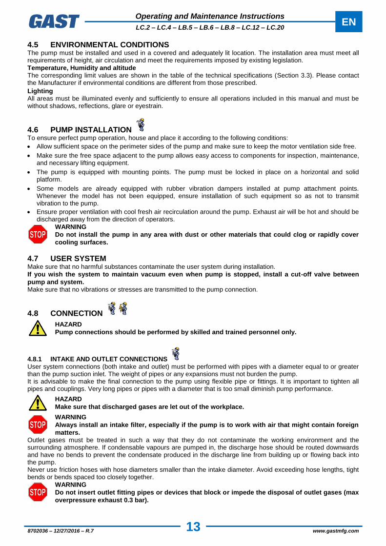
4.5 ENVIRONMENTAL CONDITIONS The pump must be installed and used in a covered and adequately lit location. The installation area must meet all requirements of height, air circulation and meet the requirements imposed by existing legislation.
Temperature, Humidity and altitude The corresponding limit values are shown in the table of the technical specifications (Section 3.3). Please contact the Manufacturer if environmental conditions are different from those prescribed.
Lighting All areas must be illuminated evenly and sufficiently to ensure all operations included in this manual and must be without shadows, reflections, glare or eyestrain.
4.6 PUMP INSTALLATION To ensure perfect pump operation, house and place it according to the following conditions:
Allow sufficient space on the perimeter sides of the pump and make sure to keep the motor ventilation side free.
Make sure the free space adjacent to the pump allows easy access to components for inspection, maintenance, and necessary lifting equipment.
The pump is equipped with mounting points. The pump must be locked in place on a horizontal and solid platform.
Some models are already equipped with rubber vibration dampers installed at pump attachment points. Whenever the model has not been equipped, ensure installation of such equipment so as not to transmit vibration to the pump.
Ensure proper ventilation with cool fresh air recirculation around the pump. Exhaust air will be hot and should be discharged away from the direction of operators.
WARNING
Do not install the pump in any area with dust or other materials that could clog or rapidly cover
cooling surfaces.
4.7 USER SYSTEM Make sure that no harmful substances contaminate the user system during installation.
If you wish the system to maintain vacuum even when pump is stopped, install a cut-off valve between
pump and system. Make sure that no vibrations or stresses are transmitted to the pump connection.
4.8 CONNECTION
HAZARD
Pump connections should be performed by skilled and trained personnel only.
4.8.1 INTAKE AND OUTLET CONNECTIONS User system connections (both intake and outlet) must be performed with pipes with a diameter equal to or greater than the pump suction inlet. The weight of pipes or any expansions must not burden the pump. It is advisable to make the final connection to the pump using flexible pipe or fittings. It is important to tighten all pipes and couplings. Very long pipes or pipes with a diameter that is too small diminish pump performance.
HAZARD
Make sure that discharged gases are let out of the workplace.
WARNING
Always install an intake filter, especially if the pump is to work with air that might contain foreign
matters. Outlet gases must be treated in such a way that they do not contaminate the working environment and the surrounding atmosphere. If condensable vapours are pumped in, the discharge hose should be routed downwards and have no bends to prevent the condensate produced in the discharge line from building up or flowing back into the pump. Never use friction hoses with hose diameters smaller than the intake diameter. Avoid exceeding hose lengths, tight bends or bends spaced too closely together.
WARNING
Do not insert outlet fitting pipes or devices that block or impede the disposal of outlet gases (max
overpressure exhaust 0.3 bar).
Operating and Maintenance Instructions
EN LC.2 – LC.4 – LB.5 – LB.6 – LB.8 – LC.12 – LC.20
14
8702036 – 12/27/2016 – R.7 www.gastmfg.com
4.8.2 WIRING
WARNING
Check that network voltage and frequency correspond to values contained on the motor rating
plate. The connection cable must be adequate for the power absorbed by the pump (absorption values are shown on the pump motor rating plate) taking into account the environmental conditions of operation.
HAZARD
Always ground the pump.
Always install a security system between the pump and the electric power supply. Pump absorption values are shown on the motor rating plate. The pump is normally supplied without an electrical cable and switch. For electrical connection, see the diagram contained within the terminal board or on the motor rating plate.
WARNING
Check that the direction of rotation is correct before starting the pump for the first time or after
changing the electrical connections.
The correct direction of rotation is indicated by the arrow on the pump (see section 3.3). Pump
operation with a rotation direction that is opposite to that indicated can severely damage the
pump itself.

Operating and Maintenance Instructions
EN LC.2 – LC.4 – LB.5 – LB.6 – LB.8 – LC.12 – LC.20
15
8702036 – 12/27/2016 – R.7 www.gastmfg.com
5 OPERATING INSTRUCTIONS
5.1 OPERATION
Checks to be performed before start-up:
The pump is supplied without any oil in it. Use the supplied oil or an oil lubricant indicated on the identification plate of this pump (see section 3.3) or, alternatively, an alternative lubricant of another brand but with similar characteristics;
Make sure the pump outlet is not obstructed by fittings.
WARNING
A quantity of oil that exceeds the necessary quantity may cause the clogging of oil separators and
damage to the pump or to the electric motor.
Operation without lubricant causes serious damage to the pump.
5.1.1 FILLING THE OIL TANK
WARNING
When filling the oil tank never exceed allowed maximum level.
Undo the oil filler plug;
Pour oil in the tank up to mid-range of the oil sight glass;
Close the filler plug
Remove all oil spills from the pump and/or floor.
5.1.2 START-UP
HAZARD
The pump may reach high temperatures when operating.
After start-up, the pump may run slower than the regular rpm if room temperature is lower than allowed as seen on the technical data table. It may also run lower if the oil is contaminated or the supply voltage is lower than the required voltage as indicated on the motor rating plate. If nominal rpm is not reached within a few seconds, the thermal switch fitted to protect the pump must trip (installation required in paragraph "Wiring").
WARNING
If water vapour should be taken in, take the pump to a steady temperature by leaving it to run for
approximately 30 minutes with the suction inlet closed and the system containing the water
vapour isolated before starting the work cycle.
WARNING
Make sure the pump is working at the allowed pressure value and do not leave the pump running
for a long time with the suction inlet completely open.
HAZARD
Full R.P.M. pump operation must be without vibration or unusual noise. If these are present, stop
the pump immediately, search for the cause and eliminate it.
5.1.3 STOP The pump must be stopped by cutting off the power supply. If the pump is to be powered off, let it run with closed intake for about 30 minutes first. This will eliminate any moisture inside the intake chamber and avoid rotor oxidation. In the case of long machine downtime, completely empty the pump to avoid hazards of frost during cold weather or corrosion due to possible chemical alteration of the stagnant liquid in the pump.
5.1.4 PUMPING WATER VAPOUR While operating in the presence of water vapour, the pump takes in a mixture of air and water which enters the pump and therefore also the oil tank. The aspirated water vapour is expelled by the heat generated by the pump during operation. On models LB.5, LC.12 and LC.20 there is an integrated regulating ballast which ensures the constant flow of ambient air from the pumping room, allowing the expulsion of aspirated water vapour before it condenses into the lubricating oil.
Therefore, if water vapour is present, it is essential that before the work cycle is started the pump must
reach its operating temperature – this is achieved by running it for about 30 minutes with the suction inlet
closed and isolating it from the user system.

Operating and Maintenance Instructions
EN LC.2 – LC.4 – LB.5 – LB.6 – LB.8 – LC.12 – LC.20
16
8702036 – 12/27/2016 – R.7 www.gastmfg.com
6 MAINTENANCE
6.1 GENERAL WARNINGS For good maintenance:
Immediately verify the causes of any malfunctions (excessive noise, overheating, etc.);
Pay particular attention to safety devices;
Make use of all documentation provided by the manufacturer (instruction manuals, wiring diagrams, etc.);
Use only appropriate tools and original spare parts.
In the event of a failure to understand the information or procedures contained in this section, contact Gast for clarification before proceeding.
HAZARD
Do not perform any type of operation, modification and/or repair of any kind, except for those
listed in this manual.
Only trained or authorised personnel have the necessary expertise to perform tasks with the
technique appropriate for intervention.
HAZARD
All maintenance operations must be carried out with the pump disconnected from any power
sources. Do not operate the pump until it has reached a temperature that is not dangerous for
the operator.
HAZARD
If pump maintenance has been performed in a manner inconsistent with instructions, with
non-original spare parts or otherwise so as to impair its integrity or modify its characteristics,
Gast will be released from any liability relating to the safety of persons and malfunction of the
pump.
6.2 MAINTENANCE TABLE The following table shows all required periodic operations to maintain pump efficiency.
OPERATION TYPE FREQUENCY OPERATOR
QUALIFICATION
Check the oil level 24 h
Change oil 500 h
Clean motor fan guard and clean pump 1000 h
Change the air exhaust filter 2000 h
Change vanes 10000 h
Shorter maintenance intervals may be required according to operating conditions (high temperature of intake gases, intake gases containing condensable vapours, etc.).
6.2.1 CHECK OIL LEVEL Check that oil level is at mid-range of the oil sight glass. If not, see instructions in the following paragraph. Check oil conditions. When dark or cloudy, oil has been contaminated by intake substances and must be changed.
6.2.2 CHANGE OIL Change oil as follows:
Let the pump run with closed suction intake for about 10 minutes first so oil will become thinner;
Stop the pump and disconnect it from the power supply;
Undo the oil filler plug;
Get a container large enough to hold all oil and open the oil drain plug;
Drain out all oil;
Close drain plug and fill in fresh oil through the filler plug up to mid-range on the oil sight glass;
Close the oil filler plug;

Operating and Maintenance Instructions
EN LC.2 – LC.4 – LB.5 – LB.6 – LB.8 – LC.12 – LC.20
17
8702036 – 12/27/2016 – R.7 www.gastmfg.com
Reconnect the power supply and verify correct rotation direction of the pump (see section 3.3.);
Let the pump run with closed intake for a few minutes and then, if necessary, top up oil.
HAZARD
Wear appropriate personal protection equipment to perform said operations.
HAZARD
Comply with local regulations regarding the collection and disposal of used or polluted oil.
6.2.3 CLEAN MOTOR FAN GUARD EAND CLEAN THE PUMP Radiator, motor fan guard and the pump should be cleaned to remove any dust deposits. This can be done using compressed air and a dry cloth. Do not use fluids or substances other than those indicated.
HAZARD
Wear appropriate personal protection equipment to perform said operations.
6.2.4 CHANGE THE AIR EXHAUST FILTER The air exhaust filter must be changed when it is damaged or clogged or when it has reached its authorised life as per section 6.2. Only use original Gast filters from the Air Exhaust Filter Kit (see Section 6.3). Use of parts other than those approved by Gast can cause deterioration of the pump. The signs showing a filter is clogged or damaged are increased exhaust fumes, increased noise-level and consumption of electricity (see Section 9 parts C and E). It is possible to measure the level of clogging of the oil separator filter by looking at the ΔP of the filter with the pump warm. On pumps equipped with a measuring point for ΔP it is possible to check the filter by attaching a gauge or the accessory code SIF.2 to it. For pumps without this facility a measuring instrument can be connected in place of the oil filler cap. For a pump operating and with hot oil the filter is clogged if the value of ΔP is greater than 0.7bar (at sea level). If this is the case the oil separator filter must be replaced.
6.2.5 CHANGE VANES The instructions for replacing vanes are available upon request.
6.3 SPARE PARTS Use Original Spare Parts to replace pump parts. When purchasing spare parts, always quote the serial number and model of the pump (these can be found on the identification plate) as well as the spare part purchase number.
DESCRIZIONE LC.2 LC.4 LB.5 LB.6 LB.8 LC.12 LC.20
Air exhaust filter kit K9601069 K9601070 K9601062 K9601058 K9601055 K9601064 K9601066
Maintenance kit K9601069/1 K9601070/1 K9601062/1 K9601058/1 K9601055/1 K9601064/1 K9601066/1
Oil 0,25 dm³ 8811025 (BV32) 8831025 (SW40)
8812025 (BV68)
8832025 (SW60)
8811025 (BV32) 8831025 (SW40)
Oil 0,5 dm³ 8811050 (BV32) 8831050 (SW40)
8812050 (BV68)
8832050 (SW60)
8811050 (BV32) 8831050 (SW40)
Oil 1 dm³ 8811100 (BV32) 8831100 (SW40)
8812100 (BV68)
8832100 (SW60)
8811100 (BV32) 8831100 (SW40)
Oil sight glass 1105005 1105004 1105009 1105004
Check valve Fitted
Gast disclaims all responsibility for any deterioration of pump performance or for damages caused due to use of non-original spare parts.
Operating and Maintenance Instructions
EN LC.2 – LC.4 – LB.5 – LB.6 – LB.8 – LC.12 – LC.20
18
8702036 – 12/27/2016 – R.7 www.gastmfg.com
7 HOW TO RETURN THE PUMP The product may only be returned after prior agreement with the supplier, who will provide the authorisation number that must accompany the material delivered and should be duly complete in its entirety.
8 DISMANTLING Demolition of the pump must be performed by authorised technicians. Metal parts can be disposed of as scrap metal. All materials deriving from demolition must be disposed of according to regulations of the location where the pump will be disposed of.
HAZARD
Disposal operations involve risks of cutting, shavings protection, entanglement, contact with
moving parts and contact with chemicals. Operators should use the appropriate personal
protective equipment.

Operating and Maintenance Instructions
EN LC.2 – LC.4 – LB.5 – LB.6 – LB.8 – LC.12 – LC.20
19
8702036 – 12/27/2016 – R.7 www.gastmfg.com
9 TROUBLESHOOTING
DAMAGE CAUSE REMEDY
(A)
The pump does not run
No voltage Provide power supply
Thermal switch has tripped Identify reason and activate switch
Room temperature is too low Restore room temperature to allowed
range
Motor winding damaged Contact Technical Department
(B)
The pump cannot
reach stated vacuum
Low oil in tank Top up oil
Oil contaminated Change oil
Discharge clogged Check couplings at outlet
(C)
Pump is noisy
Air exhaust filter clogged Change the air exhaust filter
Bearings damaged Contact Technical Department
Vanes worn out Contact Technical Department
(D)
Pump runs hot
Oil is not the suitable type Change oil
Poor room ventilation Install an auxiliary ventilator
Motor fan broken Contact Technical Department
Wrong power supply to motor Check power supply
Discharge clogged Check couplings at outlet
(E)
High oil consumption
High working pressure (close to atmospheric pressure)
Check oil level frequently
Pump runs hot See point “D”
Air exhaust filter clogged Change the air exhaust filter
(F)
Pump does not
maintain vacuum after
power-off
Check valve damage (if fitted) Contact Technical Department
(G)
Pump leaks oil
Tank screws or plugs loosened Tighten screws or plugs
Tank gaskets damaged Contact Technical Department
Oil sight glass not tightened Tighten the oil sight glass
Operating and Maintenance Instructions
EN LC.2 – LC.4 – LB.5 – LB.6 – LB.8 – LC.12 – LC.20
20
8702036 – 12/27/2016 – R.7 www.gastmfg.com
GENERAL CONDITIONS OF SALE
Gast supplies products exclusively for professional clientele, hence, excluding consumers.
PRODUCT WARRANTY TERMS AND CONDITIONS
Gast guarantees that the product is free from material or manufacturing defects for a period of 12 months of normal use from the shipping date. This period is of 6 months of normal use for products subject to repair not under warranty. Normal use means an operating cycle of 8 hours per day for a maximum of 5000 operating hours in the 12 months covered by the warranty.
Warranty means the free replacement or repair at its own assistance network of any components of the product that are found to be faulty from the start due to manufacturing defects.
In the event of repair, Gast guarantees, exclusively to its own customer, the identical spare parts for 12 months from the shipping date; once this period has passed, the pieces may no longer be available on the market, therefore the repairs, even under warranty, may require the payment of a difference between the product purchased and that installed during the repair. This price will be indicated to the customer before the repair is carried out, for acknowledgement and acceptance. Gast will do everything reasonable within its power to respect the assistance times and standard response (20 working days), which may vary according to the distance and accessibility of the place where the product is located and the availability of the components. Gast will not be held responsible for any direct or indirect losses caused by its failure to respect the assistance times and will not have any responsibility or contractual or civil obligation for product faults or for failure to repair the faults in a reasonable period of time. In the event of irreparable faults, the product will be replaced. The replacement will cause the original warranty to be extended to the new product, until its expiration date. The warranty does not cover any parts that appear to be faulty due to negligence and/or carelessness during use (failure to observe the equipment operating instructions, lack of maintenance), incorrect installation and/or maintenance, maintenance carried out by unauthorized staff, damage due to transport, or circumstances which, in any case, cannot be attributed to manufacturing faults on the equipment. The warranty also excludes all components of the product that have been modified or repaired without prior written authorisation from Gast.
The warranty also excludes any faults deriving from improper use, normal wear, galvanic and electrostatic currents, chemical corrosion, tampering, replacement or elimination of the registration plate. The warranty does not cover, in any case, faults generated by external causes, such as accidents and fortuitous events.
Gast declines all responsibility to anyone for any damage and, consequence, of any kind and/or reason, that may derive from the use of the product, as well as for any faults that it may present. By way of non-limiting example, it declines all responsibility:
for any damage that could, directly or indirectly, be caused to people, objects and animals, due to failure to observe all the instructions indicated in the relevant use and maintenance manual, especially the indications on the installation, use and maintenance of the equipment;
for any damage and/or loss caused by faults of deficiencies of products repaired by Gast;
for any indirect or consequential damage such as, by way of non-limiting example, loss of business, profits, salaries, payments etc.;
losses that could have been avoided by the customer by following the advice and instructions from Gast.
In any case, the customer waives the right to claim any right and/or demand as well as raising any objection or promoting any action, inherent to the use of the product.
The warranty is not extended to consumable parts, or faults deriving from: filtering cartridges, blades, membranes or sealing rings, as well as third party products that are part of the final product.
The transport, removal and subsequent re-installation costs of the repaired or replaced product are, however, to be entirely borne by the customer.